Loading ...
Loading ...
Loading ...
10
36” GAS RANGETOP INSTALLATION INSTRUCTIONS
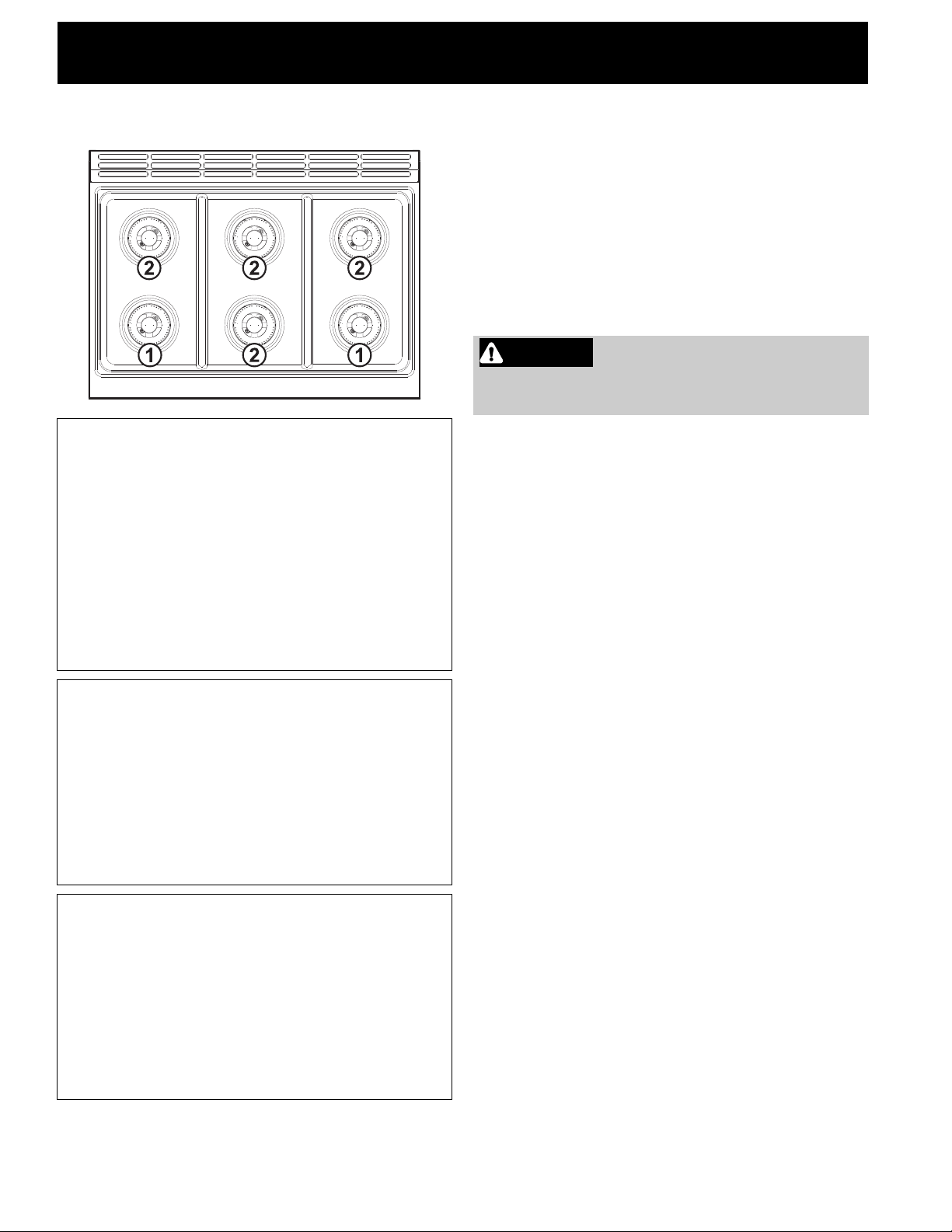
The technical data tables for the nozzles and burn-
ers are shown below
:
Connect the gas supply line to the unit pressure reg-
ulator using a 1/2” flex gas line connector between
the manual shut-off valve and the pressure regula-
tor. A metal flex line or fixed metal pipe must be
used to connect the gas to the appliance. If a metal
gas line cannot be used, consult your local certified
electrician or local electric codes for proper ground-
ing.
Check the supply line connections for leaks using a
soap solution or non-corrosive leak detection fluid.
Do not use a flame of any sort.
1. Turn on gas.
2. Apply a soap solution or non-corrosive leak
detection fluid to all joints and fittings in the gas
connection between the shut-off valve and the
cooktop. Include gas fittings and joints in the
cooktop if connections may have been disturbed
during installation. Bubbles appearing around fit-
tings and connections indicate a leak.
3. If you detect a leak, turn off supply line gas shut-
off valve and tighten connections.
4. Retest for leaks by turning the gas supply line
shutoff valve on. When the leak check has been
completed (no bubbles appear), the test is com-
plete.
5. Wipe off all residues of the soap solution or
detection fluid.
Important Notes for Gas Connection:
• The appliance and its individual gas shutoff valve
must be disconnected from the gas supply piping
system during pressure testing of the system at
test pressures in excess of 1/2 psi (3.5kPa).
• The appliance must be isolated from the gas sup-
ply piping system by turning off its individual man-
ual shut-off valve during pressure testing of the
gas supply piping system at test pressures equal
to or less than 1/2 psi (3.5kPa).
Burner power and bypass table
Burner
No.
12
Max.
Power
(BTU)
18000 12000
Min.
Power
(BTU)
750 750
Bypass
(mm)
75 / 26 55 / 26
Natural gas nozzles table (Pressure in W.C.P.: 5”)
Burner
No.
12
Ext.
nozzle
number
180 135
Int. noz-
zle
number
75 75
LPG nozzles table (Pressure in W.C.P.: 10”)
Burner
No.
12
Ext.
nozzle
number
115 91
Int. noz-
zle
number
48 48
WARNING Install a gas shutoff valve near the
appliance. After installation, it must be easily
accessible in an emergency.
Loading ...
Loading ...
Loading ...