Loading ...
Loading ...
Loading ...
© FISHER & PAYKEL LIMITED 202 PAGE 99000269A PLANNING GUIDE MODULAR COOKTOPS VERSION 1 - AUGUST 202 © FISHER & PAYKEL LIMITED 202 PAGE 99000269A PLANNING GUIDE MODULAR COOKTOPS VERSION 1 - AUGUST 202
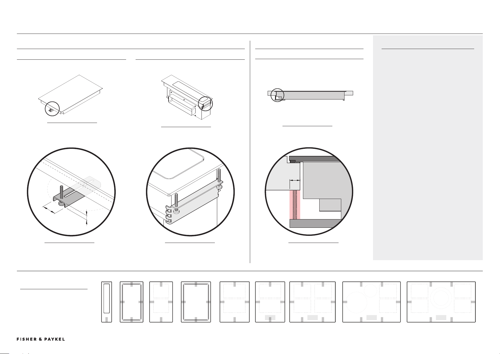
CLAMPS
Clamps are suplied with modules to secure
their postition to benchtop. There are two
types, common and rear downdraft.
It is recommended to have 10mm clearance
from edge of cutout for clamp engagement..
Clamps are attached to chassis at fixed hole
locations. A minimum of 2 clamps are required
per module, it is recommended they are
positioned on opposite sides of each module
eg. left and right or front and rear.
For more details please refer to Install Guide.
CLAMP FIXING LOCATIONS
PLAN VIEW
Minimum of 2 clamps per
module. For specific locations
please refer to data sheets.
DETAIL A
Can be rotated and
moved horizontally
ISO FRONT VIEW
ISO REAR VIEW
SIDE VIEW
CLEARANCE REQUIREMENTS
ALL MODULES
BRACKET TYPES
COMMON BRACKET REAR DOWNDRAFT BRACKET
Applies to all bracket locations, exluding rear downdraft
10mm
25mm
10mm
9cm 60cm0cm 76cm 90cm9cm 9cm0cm
DETAIL B
Bracket can be be
repositioned vertically
A
B
C
DETAIL C
Minimum clearance
common to all brackets
left/right amd font/rear
PLANNING CONSIDERATIONS | MODULAR COOKTOPS CLAMPING LOCATIONS
Loading ...
Loading ...
Loading ...