2023.10v1.0
User Manual
Searching for Keywords
Search for keywords such as “battery” and “install” to nd a topic. If you are using Adobe
Acrobat Reader to read this document, press Ctrl+F on Windows or Command+F on Mac
to begin a search.
Navigating to a Topic
View a complete list of topics in the table of contents. Click on a topic to navigate to that
section.
Printing this Document
This document supports high resolution printing.
This document is copyrighted by DJI with all rights reserved. Unless otherwise authorized by
DJI, you are not eligible to use or allow others to use the document or any part of the document
by reproducing, transferring or selling the document. Users should only refer to this document
and the content thereof as instructions to operate DJI UAV. The document should not be used
for other purposes.
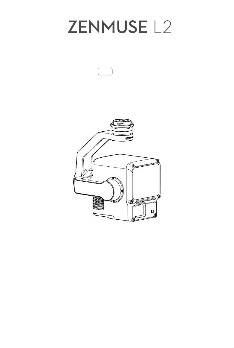
ZENMUSE L2
User Manual
©
2023 DJI All Rights Reserved.
1
Using This Manual
Legends
Important Hints and Tips
Video Tutorials
Go to the address below or scan the QR code to watch the tutorial videos, which demonstrate
how to use the product safely.
https://enterprise.dji.com/zenmuse-l2/video
Warnings
1. This product is a precision instrument. DO NOT drop it and handle with care.
2. DO NOT expose the LiDAR to strong sources of energy such as a laser beam or any other
LiDAR in use. Otherwise, the LiDAR may be permanently damaged.
3. If highly accurate point cloud data is required, it is not recommended to use the L2 in low
visibility conditions such as foggy or rainy weather. Otherwise, the detection range may be
reduced leading to point cloud noise. Refer to the LiDAR Usage Scenario section for more
information.
4. DO NOT touch the optical window of the product. Dust and stains on the optical window
can negatively aect the performance. Use compressed air or a wet lens cloth to clean the
optical window correctly. Refer to the Storage, Transportation, and Maintenance section for
more information on how to clean optical windows.
5. DO NOT touch the surface of the lens with your hand. Be careful to avoid scratching the
surface of the lens with sharp objects. Otherwise, the quality of images may be aected.
Clean the surface of the camera lens with a soft, dry, clean cloth. DO NOT use substances
containing alcohol, benzene, thinners, other ammable substances, or alkaline detergents
to clean or maintain the RGB Mapping Camera.
6. When not in use, store the product in the storage case and replace the desiccant packet as
necessary to prevent fogging of the lenses due to excessive ambient humidity. If the lenses
fog up, the water vapor will usually dissipate after powering on the device for a while. It is
recommended to store the product in an environment with a relative humidity of less than
40% and temperature range of 15° to 25° C (59° to 77° F).
7. DO NOT place the product under direct sunlight, in areas with poor ventilation, or near a
heat source such as a heater.
8. DO NOT repeatedly power the product on or off. After powering off, wait at least 30
seconds before powering back on. Otherwise, the product life will be aected.

ZENMUSE L2
User Manual
2
©
2023 DJI All Rights Reserved.
9. Under stable laboratory conditions, the product achieves an IP54 protection rating by
IEC 60529 standards. The protection rating is not permanent and may reduce over an
extended period.
10. Make sure there is no liquid on the surface or in the port of the gimbal.
11. Make sure the gimbal is securely installed on the aircraft and the microSD card slot cover is
properly closed.
12. Make sure the surface of the gimbal is dry before opening the microSD card slot cover.
13. DO NOT remove or insert the microSD card when taking a photo or recording a video.

©
2023 DJI All Rights Reserved.
3
Using This Manual 1
Legends 1
Video Tutorials 1
Warnings 1
Product Profile 5
Introduction 5
Overview 5
Installation 5
Remote Controller Controls 7
DJI Pilot 2 App 8
Basic Features 8
Point Cloud LiveView 10
Point Cloud Preview 11
Point Cloud Playback 11
Point Cloud Merging 12
Field Data Collection 14
Getting Started 14
Area Route 14
Recording Point Cloud Data 14
Terrain Follow 16
Waypoint Route 17
Set Waypoints 17
Live Mission Recording 18
Route Parameters 18
Manual Flight 20
Task Quality Report 20
Point Cloud Data File Description 22
PPK Data Acquisition 22
Office Data Processing 24
Downloading DJI Terra 24
Reconstruction Procedures 24
LiDAR Description 26
Non-repetitive Scanning Method 26
Contents

ZENMUSE L2
User Manual
4
©
2023 DJI All Rights Reserved.
Repetitive Scanning Method 26
Point Cloud Density 27
LiDAR Usage Scenario 28
Maintenance 29
Log Export 29
Firmware Update 29
Using DJI Pilot 2 29
Using microSD Card 29
Update Status Alarm 30
L2 Calibration 30
Re-calibrating the Internal and External Parameters 30
Restoring the Internal and External Parameters to Default Settings 31
Storage, Transportation, and Maintenance 31
Storage 31
Transportation 31
Maintenance 32
Specifications 33
ZENMUSE L2
User Manual
©
2023 DJI All Rights Reserved.
5
Product Prole
Introduction
The ZENMUSE
TM
L2 integrates a LiDAR module, a high-accuracy IMU, and an RGB mapping
camera on a 3-axis stabilized gimbal, which can be used with specied compatible DJI
TM
aircraft.
With Point Cloud LiveView, users can take a quick view of the 3D point cloud eect in the DJI
PILOT
TM
2 app. When used with DJI TERRA
TM
, the L2 oers a complete solution that generates
point cloud output and extracts ground points to generate DEM results, which efficiently
completes highly accurate reconstructed models of complex structures.
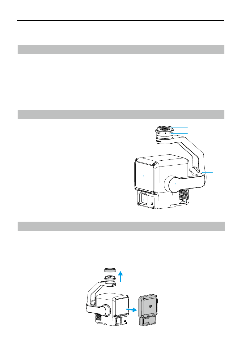
Overview
1. Gimbal Connector
2. Pan Motor
3. Roll Motor
4. Tilt Motor
5. microSD Card Slot
6. RGB Mapping Camera
7. LiDAR
Installation
The L2 can be mounted to MATRICE
TM
300 RTK (requires DJI RC Plus) or Matrice 350 RTK aircraft.
1. Remove the gimbal cap and lens cap.
11
2
3
1
2
3
4
5
6
7

ZENMUSE L2
User Manual
6
©
2023 DJI All Rights Reserved.
11
2
3
2. Press the button on the aircraft used for detaching the gimbal and camera. Rotate and
remove the gimbal cap on the aircraft.
3. Align the white dot on the gimbal with the red dot on the aircraft and insert the gimbal.
4. Rotate the gimbal lock to the locked position by aligning the red dots.
• To ensure the mapping accuracy, make sure the L2 is mounted on a single downward
gimbal connector with the cable connected to the right USB-C port (when facing the
aircraft).
• Make sure the gimbal connector on the aircraft is positioned correctly when mounting.
Otherwise, the payload cannot be mounted.
• Only remove the payload after powering o the aircraft.
• Remove the payload by pressing the button on the aircraft to detach the gimbal and
camera.
• Make sure the microSD card slot cover is rmly in place to prevent dust or moisture
entering during usage or transportation.
• To avoid burns, DO NOT touch the camera case and the optical window when powering
on.
• Detach the gimbal from the aircraft during transportation or storage. Otherwise, the
service life of the damper balls may be shortened or they may even be damaged.
ZENMUSE L2
User Manual
©
2023 DJI All Rights Reserved.
7
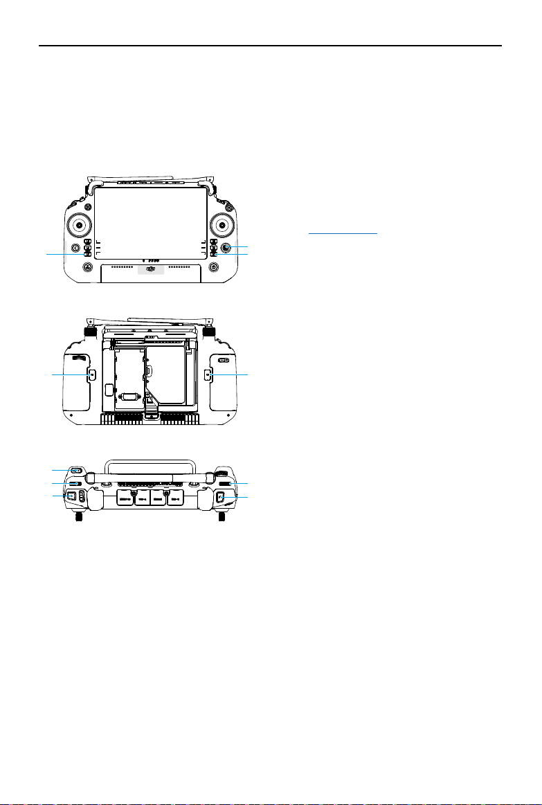
Remote Controller Controls
With the buttons on the DJI RC Plus remote controller, users can switch display modes between
point cloud and visible light live views, preview the point cloud eect, and control the gimbal
and camera.
1. L1/L2/L3/R1/R2/R3 Buttons
Go to Camera View in DJI Pilot 2 to view the
specic functions of these buttons. Refer to
the DJI Pilot 2 App section for details.
2. 5D Button
View and customize the 5D button functions
in DJI Pilot 2.
3. Customizable C1/C2/C3 Buttons
Customize the function of these buttons in
DJI Pilot 2.
4. Left Dial
Adjust the tilt of the gimbal.
5. Record Button
Press once to start or stop recording.
6. Focus/Shutter Button
Press the button halfway down for
autofocus and all the way down to take a
photo.
7. Right Dial
Adjust the pan of the gimbal.
1
3
3
4
5
1
3
6
7
2

ZENMUSE L2
User Manual
8
©
2023 DJI All Rights Reserved.
DJI Pilot 2 App
In the DJI Pilot 2 app, users can perform a ight task or use Manual mode to record point cloud
data. After the ight task, the user can preview the 3D models or even merge models collected
from multiple ight tasks.
Basic Features
In Camera View, the touch interface can display a live view and oers professional photography
congurations.
1. View Type
Displays the current camera type including the visible light view, the LiDAR view, and the
side-by-side view.
2. Camera Parameters
Displays the current camera parameters.
3. Auto Exposure Lock
Tap to lock the current exposure value.
4. Focus Mode
Tap to switch between MF (manual focus), AFC (continuous autofocus), and AFS (single
autofocus).
5. Storage Info
Displays the available storage capacity of the microSD card.
6. Exposure Settings
The L2 supports Auto, S, A, and M exposure modes. EV, AE lock, ISO, shutter, and other
1 2 3
6
7
8
9
10
11
12
13
21
20
19
18
17
1516
14
22
4 5

ZENMUSE L2
User Manual
©
2023 DJI All Rights Reserved.
9
parameters can be congured accordingly in dierent exposure modes.
7. IMU Calibration Status
Tap Calibrate to perform an IMU calibration to calibrate the LiDAR’s inertial navigation
system and increase the accuracy of data reconstruction.
A calibration ight should be performed at both the start and end of a ight. Make sure
there are no obstacles within a 30m radius of the start and end points.
8. Camera Settings
Tap to enter the photo and video settings. The settings may vary according to different
recording modes.
• Dewarping is disabled by default. Users can tap > Dewarping in the camera
settings to enable this function to eliminate or reduce distortion and vignetting in
the visible light view.
9. Recording Mode (Shutter/Video Record/Point Cloud Record)
Tap to switch between photo, video, and point cloud recording modes.
10. Shooting Button (Shutter/Video Record/Point Cloud Record)
Tap to take photos or start and stop recording video or point cloud data.
11. Playback
Tap to enter the album to view and download photos and videos stored in the microSD
card. Select the point cloud data le to preview the 3D model. Refer to Point Cloud Playback
for details. Select multiple les to view the merging models. Refer to Point Cloud Merging
for details.
12. Press the R2 button on the remote controller to preview the current point cloud model
during eldwork. Refer to Point Cloud Preview for details.
13. Press the R3 button on the remote controller to switch to FPV camera view.
14. FPV Live View
Tap to display the FPV camera view on the screen. Users can maximize or minimize the
view.
15. Navigation Display
In Camera View, the horizontal speed, wind speed, gimbal pitch angle and pitch scale, and
the inclination of the gimbal relative to the ground are shown on the left of Navigation
Display. The right shows the altitude, relative altitude, vertical obstacle sensing information,
and vertical speed bar.
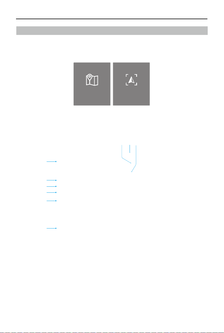
16. Map View
Tap to display the map view on the screen. Users can maximize or minimize the view.
17. Laser PinPoint
Press the L3 button on the remote controller to add a PinPoint in the center of the screen.
Tap to select a PinPoint on the map to view the distance between the subject and the
aircraft or the altitude, latitude, and longitude of the subject. The laser PinPoints can be
projected onto the live view.

ZENMUSE L2
User Manual
10
©
2023 DJI All Rights Reserved.
18. Press the L2 button on the remote controller to switch between the visible light view and
the LiDAR view.
19. Press the L1 button on the remote controller to switch to side-by-side display with visible
light and LiDAR live view.
20. Gimbal Mode
Displays the current gimbal status as follow mode. Tap to select an action such as gimbal
recenter, gimbal pan recenter, gimbal tilt down, or gimbal down, or switch to gimbal free
mode.
21. Laser Rangender (RNG)
The cross hair in the center of the live view will turn red, which means the laser rangender
is pointing at the subject and measuring the distance between the subject and the aircraft,
as well as the altitude, latitude, and longitude of the target.
22. Flight Route
Tap to enter the ight route library. Users can create and view all ight tasks and more.
Point Cloud LiveView
With Point Cloud LiveView, users can take a quick view of the real-time point cloud eect using
the LiDAR view or side-by-side view.
23. Coloring Coding
Tap to select a rendering mode including reectivity, height, distance, and RGB.
24. Pause Button
Tap to pause recording and tap again to resume.
25. Press the R1 button on the remote controller to switch the rendering mode.
23
25
24

ZENMUSE L2
User Manual
©
2023 DJI All Rights Reserved.
11
Point Cloud Preview
Press the R2 button on the remote controller during a ight task to preview the point cloud 3D
model recorded in real time.
26. Tap to view the point cloud model from above or in the direction of north, east, south, or
west.
27. Press the R2 button on the remote controller to exit the preview.
28. Displays the current orientation.
29. Press the L2 button on the remote controller to view the point cloud model beneath the
aircraft.
30. Press the L1 button on the remote controller, the model will recenter and zoom in or out to
display the whole model.
Point Cloud Playback
Tap to enter the album and download the point cloud data les to preview the 3D models
directly*, allowing users to check the quality on-site and improve work eciency.
* The model displayed in point cloud playback is generated using sparse point clouds.
26
27
28
29
30

ZENMUSE L2
User Manual
12
©
2023 DJI All Rights Reserved.
31. Screen Gestures
Displays the supported control gestures when entering the view for the rst time.
32. Point Cloud Merging
Press the L3 button on the remote controller to select multiple point cloud data les and
view the merging model.
Point Cloud Merging
The app supports the inspection of the results by alignment of multiple point cloud models
captured from dierent ight tasks and reviews the voids and gaps in the merging models.
31
32
33
33. Press the L3 button on the remote controller to select more point cloud data les to merge.

ZENMUSE L2
User Manual
©
2023 DJI All Rights Reserved.
13
• Make sure the aircraft and the remote controller are connected when viewing the point
cloud models.
• The point cloud data file cannot be processed when it is less than 2 kB. It is
recommended to record point cloud data for longer than 2 minutes with IMU
Calibration enabled to ensure the data is eective.
• To clear the cache, enter the album to select and delete the downloaded les or tap
Data and Privacy on the home page and then tap DJI Pilot Cache Management to clear
all downloaded point cloud data les.
ZENMUSE L2
User Manual
14
©
2023 DJI All Rights Reserved.
Field Data Collection
In the DJI Pilot 2 app, users can perform a ight task (Area Route, Waypoint Route, and Linear
Route) or use Manual mode to record point cloud data. After each task, the app will generate a
task quality report to show the validity of the data.
• Make sure to remove the microSD card after at least 60 s of stopping the shuttering or
the point cloud recording. Otherwise, the accuracy may be reduced or the data le may
be damaged.
Getting Started
1. Make sure the payload is correctly installed on the single downward gimbal connector of the
aircraft and that the aircraft and remote controller are linked after powering on.
2. Go to Camera View in DJI Pilot 2, select and then Precise Positioning Setting. Choose the
RTK service type, and then make sure that the status of RTK positioning and heading both
display FIX. Refer to PPK Data Acquisition to learn more about data processing if the network
or the remote controller video transmission signal is poor.
3. Adjust the camera parameters on the upper right corner of Camera View according to the
surroundings. Make sure the photo is well exposed. Tap to switch exposure modes. It is
recommended to set Auto mode for recording point cloud data.
Area Route
When using the area route, the aircraft can automatically complete the data collection of the
planned area along the s-shaped route according to the route parameters. Terrain follow ight
can be performed in the area route task.
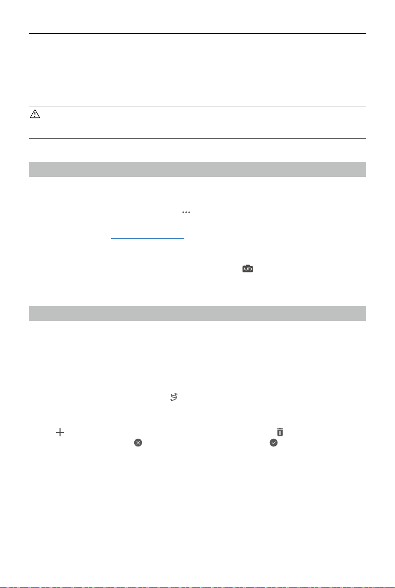
Recording Point Cloud Data
Enter Camera View in DJI Pilot 2 and tap , select Create a Route, and then Area Route to create
a ight task.
1. Tap on the map view, and drag the boundary point to adjust the range of the mapping area.
Tap in the middle of the boundary point to add a point. Tap to delete the selected
boundary point, and click to delete all boundary points. Tap to conrm the mapping
area.

ZENMUSE L2
User Manual
©
2023 DJI All Rights Reserved.
15
L2
2. Choose the aircraft, and then select Zenmuse L2, LiDAR Mapping.
3. Click OK after completing the Payload Settings, then set the ight route parameters and
Advanced Settings.
4. Tap to save the task and tap to upload and execute the ight task.
5. After the ight task, users can preview the 3D models or even merging models collected
from multiple ight tasks.
6. Power o the aircraft after completing the task and remove the microSD card from the L2.
Insert the microSD card into a computer and check the point cloud data and other les in
the DCIM folder.
• Refer to Route Parameters for more information.
• For LiDAR Mapping, it is recommended to set the Side Overlap (LiDAR) to above 20%,
the Scanning Mode to Repetitive, the altitude to 150 m, the ight speed to 15 m/s, and
also to enable IMU Calibration.
• It is recommended to disable Dewarping and set Forward Overlap (Visible) and Side
Overlap (Visible) to default parameters in a Photogrammetry task.

ZENMUSE L2
User Manual
16
©
2023 DJI All Rights Reserved.
Terrain Follow
Set the altitude mode to AGL (altitude relative to ground) to enable the terrain follow function.
By importing the DSM le including the altitude information or downloading the DEM le from
internet, the app will generate a ight with altitude changes to ensure the relative height of the
aircraft and the ground below remains unchanged.
Preparing Files
The DSM les of the mapping area can be obtained using the following two methods:
1. Importing Local File
• Collect the 2D data of the mapping area and perform a 2D reconstruction using DJI Terra
by selecting Mapping Scenarios. A gsddsm.tif le will be generated and can be imported
to the microSD card of the remote controller.
• Download the terrain mapping data from a geobrowser.
2. Downloading from Internet
DSM les can be directly obtained by downloading the open source data of the ASTER GDEM
V3 geoid database.
• Make sure the DSM file is a geographic coordinate system file, not a projected
coordinate system file. Otherwise, the imported file may not be recognized. It is
recommended that the resolution of the imported file should be no more than 10
meters.
• Make sure that the mapping area is within the range of the DSM le.
• The open-source geoid database may have errors. DJI is not responsible for the
accuracy, authenticity, or validity of the data. Pay attention to the ight environment. Fly
with caution.
Importing Files
1. Set the altitude mode to AGL and tap Select DSM File. Tap and select Download from
Internet or Import Local File. Choose the file and tap Import, and wait for the file to be
imported.
2. The imported les will be displayed in the list.
Planning a Flight Task
1. Set the altitude mode to AGL and tap Reselect to select a le from the DSM le list.
2. Edit the parameters in Area Route. Set the terrain follow height and enable IMU Calibration.
3. Select to save the task and select to upload and execute the ight task.
4. Power o the aircraft after completing the task and remove the microSD card from the L2.
Insert the microSD card into a computer and check the point cloud data and other les in
the DCIM folder.
ZENMUSE L2
User Manual
©
2023 DJI All Rights Reserved.
17
Set Waypoints
Tap Create a Route, Waypoint, and then Set Waypoints.
Waypoint Mapping Oblique
Set Waypionts Live Mission
Recording
Waypoint Route
Waypoint Route can be planned in two ways: Set Waypoints or Live Mission Recording. Use
Set Waypoints to create a route by adding editable waypoints on the map. Use Live Mission
Recording to create a route by recording the waypoint location of the aircraft along the route.
1
9
2
3
4
5
867
L2
1. Enable or disable waypoint settings. Tap to add and edit waypoints on map when enabled.
2. Reverse Path: tap to swap the start and endpoint to reverse the ight path. S refers to the
start point.
3. Delete Selected Waypoints: tap to delete the selected waypoints.
4. Point of Interest (POI): tap to enable the POI function and a POI will be displayed on the map.
Drag to adjust its position. After a POI is added, the aircraft yaw can be set as facing the POI,
so that the aircraft nose points at the POI during the task. Tap this icon again to disable the
POI function.
5. Flight Route Information: displays the ight length, estimated ight time, waypoint quantity,
and photo quantity.
6. Parameters List: edit the route name, select the aircraft and payload, set the altitude mode
and payload settings.

ZENMUSE L2
User Manual
18
©
2023 DJI All Rights Reserved.
7. Flight Route Settings: the settings are applied to the entire route, including safe takeoff
altitude, ascend to start point, aircraft speed, aircraft altitude, aircraft yaw, gimbal control,
waypoint type, completion action, and IMU Calibration.
8. Individual Waypoint Settings: select a waypoint and set its parameters. Tap < or > to switch
to the previous or next waypoint. The settings are applied to the selected waypoint, including
aircraft speed, aircraft altitude, aircraft yaw mode, waypoint type, aircraft rotation direction,
gimbal tilt mode, waypoint actions, longitude, and latitude.
9. Save: tap to save the ight route. Select to upload and execute the ight task.
Live Mission Recording
Enter Camera View and tap . Tap Create a Route > Waypoint, and then Live Mission Recording
to create a ight mission.
1. Control the gimbal to point at the subject. Press the C1 button on the remote controller to
add a waypoint. The number of waypoints will be added accordingly.
2. Tap to save and generate the ight route. Tap the ight route name at the top left to view
and edit the ight route settings. There have two editing modes: Set Waypoints or Edit In-
Flight.
Route Parameters
Specications Description
Return Mode Supports 5 returns: single return (strongest), dual return, triple return, quad
return, and penta return.
Sampling Rate Supports 240 kHz scanning frequency.
Scanning Mode Supports both repetitive scanning and non-repetitive scanning.
Repetitive scanning is suitable for topographic mapping, with higher
accuracy and even point cloud scans. Use non-repetitive scanning for
electricity and forestry data collection to generate more complete tree trunk
and electrical transmission tower models.
RGB Coloring When enabled, the user can color the point cloud using the photographs
captured by the RGB mapping camera (enabled by default). It is
recommended to disable the function during night operation.
The photographs can also be used for 2D and 3D reconstruction.
IMU Calibration It is recommended to enable IMU Calibration. The aircraft ies a Calibration
Flight at the start point, end point, and the yellow segments of a ight route.
Collection Type It is recommended to select Ortho Collection in LiDAR Mapping.
GSD GSD is the ground sampling distance of the orthophotos taken on the rst
route, i.e., the distance between two consecutive pixel centers measured
on the ground. The larger the GSD value, the lower the resolution of the
orthophotos.

ZENMUSE L2
User Manual
©
2023 DJI All Rights Reserved.
19
Altitude Mode Relative to Takeoff Point (ALT): the altitude of the aircraft relative to the
takeo point. It is recommended to use this option for a at mapping area
with no undulations and set the altitude to 150 m.
ASL (EGM96): the altitude of the aircraft relative to the EGM96 geoid.
Altitude Relative to Ground (AGL): the altitude of the aircraft relative to the
ground below. Set the altitude mode to AGL to enable the terrain follow
function and it is recommended to set the Terrain Follow Height to 150 m.
Before using the terrain follow function, please import the DSM or DEM le
including the altitude information.
Flight Route
Altitude
The altitude of the ight route of a ight task.
Elevation
Optimization
It is recommended to enable this option for orthophoto operation. When
enabled, the aircraft will y to the center of the mapping area to collect a set
of oblique images to optimize the elevation accuracy.
Flight Route
Speed
The operating speed of the aircraft after entering the ight route. This speed
is related to the forward overlap ratio.
Course Angle The route direction is parallel to the longer side of the mapping area by
default.
Completion
Action
It is recommended to set the completion action as Return to Home.
Side Overlap
Ratio
Side overlap ratio is the overlap ratio of two pictures taken on two parallel
paths.
The default laser side overlap ratio is 20%. If the mapping area has large
uctuations or higher point cloud density is required, it is recommended to
increase the overlap ratio.
Forward
Overlap Ratio
Forward overlap ratio is the overlap ratio of two pictures captured
consecutively in the same heading along the ight path.
It is recommended to set the forward overlap ratio (Visible) as 80% to
capture orthophotos during point cloud data recording.
Margin The distance of the flight area beyond the mapping area. The purpose of
setting the margin is to ensure the edge accuracy of the mapping area.
Photo Mode The default selection is Timed Interval Shot.
Safe Takeo
Altitude
After taking o, the aircraft will y up to the safe takeo altitude (relative to
the takeo point), then y to the start point of the ight route.
* If the aircraft starts a ight task during ight, the safe takeo altitude will not take
eect.
Takeo Speed The ight speed after reaching the ight route altitude and before entering
the flight route. It is recommended to set it to the maximum to improve
operational eciency.

ZENMUSE L2
User Manual
20
©
2023 DJI All Rights Reserved.
Manual Flight
1. Fly the aircraft to an appropriate height and tap Calibrate to start a calibration flight. To
ensure ight safety, enable obstacle sensing and make sure the area shaded red on the map
is clear of obstacles.
2. Fly the aircraft to the target and adjust the gimbal to an appropriate angle. Tap to start
point cloud recording after setting the camera parameters.
• It is recommended that the target be 5 to 150 meters away from the payload. Note
that the accuracy may decrease when the distance between the target and the
payload is less than 30 m.
3. Press the L1/L2 button on the remote controller to switch the display, and press the R2
button to preview the model recorded in real time during ight.
4. Tap again to nish recording. It is recommended to perform IMU Calibration again after
recording.
5. After the ight task, the user can preview the 3D models or even merge models collected
from multiple ight tasks.
6. Power o the aircraft after completing the task and remove the microSD card from the L2.
Insert the microSD card into a computer and check the point cloud data and other les in
the DCIM folder.
Task Quality Report
When finished an Area Route or a Waypoint Route task, a task quality report is generated
automatically to display the detailed information of the task and ight route status. Users can
mark the route segments with low quality in the report.
1. View the quality report using either of the following methods:
Press the C2 button on the remote
controller and follow the prompts
In the flight route library, select the desired route
and tap View Task Quality Report.

ZENMUSE L2
User Manual
©
2023 DJI All Rights Reserved.
21
2. Tap View to open the quality report. The following uses an Area Route as an example.
a. Flight route name
b. Start and end time of the task
c. The completed ight route progress when nishing the task.
d. Display the collection time for point cloud recording.
e. Switch the displayed information between RTK and IMU.
f. Display the RTK/POS data collection time and the different status of the flight route
segments.
• The RTK status of the flight route may vary in different segments, including fixed
solutions, oating/single solutions, and invalid solutions. The oating/single solutions
is available for PPK calculation.
• Tap IMU to view the POS status of the ight route, including xed solutions and invalid
solutions.
g. Flight Trajectory
The RTK/POS status of the ight route is displayed in dierent colors. If RGB Coloring is
enabled during the ight task, the location of each photo will be displayed as a round dot
on the ight trajectory.
h. Tap to display the Edit Line/Area View. Users can draw areas on the map to mark the
segments that need recording again. Set the marked area as a mapping area and create
a new Area Route task. Tap to delete the information.
• The POS data collection time includes the calibration time before and after the task.
• If the same ight route segment is recorded by several times, the quality report will
prioritize displaying the results with low quality.
a
b
c
d
e
f
h
g

ZENMUSE L2
User Manual
22
©
2023 DJI All Rights Reserved.
Point Cloud Data File Description
1. The recorded point cloud data is stored in the microSD card. The storage directory is
microSD: DCIM/DJI_YYYYMMDDHHMM_NO._XXX (XXX can be edited by the user).
2. The folder contains not only photos taken during the ight but also les with CLC (camera
LiDAR calibration le), CLI (LiDAR IMU calibration le), LDR (LiDAR data), RTK (RTK data of
main antenna), RTL (compensation data of RTK pole), RTS (RTK data of auxiliary antenna),
RTB (base station RTCM data), IMU (IMU raw data), SIG (PPK signature le), LDRT (point cloud
le for playback on the app), RPT (point cloud quality report), RPOS (real-time POS solution
data), and photos taken during ight.
PPK Data Acquisition
When the mobile network or remote controller video transmission signal is poor, use the RTCM
data of the D-RTK 2 Mobile Station or a third-party RTK base station to assist the L2 for data
post-processing. Follow the steps below:
1. Check the local operation time from the point cloud data le directory stored in the microSD
card.
2. Search for .DAT RTCM files with the same timestamp as the stored files of the D-RTK 2
Mobile Station or third-party RTK base station and follow the steps below:
a. If using the D-RTK 2 Mobile Station, copy the .DAT le with the same timestamp in the
rtcmraw folder to the folder of the point cloud data le directory.
b. If using a third-party RTK base station, .oem/.ubx/.obs/.rtcm les are supported. Rename
the le the same as the .RTB le in the point cloud data le directory by following the
name format in the table below and copy the renamed le to the folder of the point cloud
data le directory. DJI Terra will prioritize les in the following order: .oem > .ubx > .obs
> .rtcm.
Protocol Type Protocol Version Message Type Name Format
OEM OEM4, OEM6 RANGE DJI_YYYYMMDDHHMM_XXX.oem
UBX -- RAWX DJI_YYYYMMDDHHMM_XXX.ubx
RINEX v2.1x, v3.0x -- DJI_YYYYMMDDHHMM_XXX.obs
RTCM
v3.0
1003, 1004, 1012,
1014
DJI_YYYYMMDDHHMM_XXX.rtcm
v3.20
MSM4, MSM5,
MSM6, MSM7

ZENMUSE L2
User Manual
©
2023 DJI All Rights Reserved.
23
• Note that the RTCM le stored in the D-RTK 2 Mobile Station is in UTC time format.
• If using the D-RTK 2 Mobile Station, users can also directly copy all the base station data
les from that day and DJI Terra will automatically merge them.
• If using a third-party RTK base station, make sure the station supports at least three
GNSS systems.
• When setting up a third-party RTK base station, follow the steps to set the coordinates
of the origin for the RTK base station (using RINEX format as an example):
a. Erect the RTK base station to a point with known coordinates and record the XYZ
coordinates in ECEF format (use a third-party software for format conversion, if
necessary).
b. Use Notepad to open the RINEX file with the O. file and modify the APPROX
POSITION XYZ coordinates of the O. le to the coordinates recorded in step one.
• Make sure the distance between the RTK base station and the device is less than 15 km.
Otherwise, the calculation may fail. Refer to DJI Terra Quality Report for more details.
• Refer to the D-RTK 2 Mobile Station User Guide for more information.

ZENMUSE L2
User Manual
24
©
2023 DJI All Rights Reserved.
Oce Data Processing
Downloading DJI Terra
DJI Terra is required for data processing. Visit https://enterprise.dji.com/dji-terra/downloads to
download and install DJI Terra. Read the DJI Terra User Manual for more information about how
to congure DJI Terra and use reconstructions.
Reconstruction Procedures
Follow the steps below to reconstruct point cloud data in DJI Terra.
1. Launch DJI Terra, select New Mission or Import to create and save a point cloud processing
task.
2. Select on the task editing page and import the folder from the microSD card. The folder
will be named according to the time the point cloud data was recorded. The folder contains
les with the sux CLC, CLI, CMI, IMU, LDR, RTB, RTK, RTL, and RTS.
3. Congure the point cloud density and output coordinate system settings.
4. Advanced Settings
a. Ground Point Type: check the Ground Point Type and select the Ground Type based on
actual needs. Flat Ground is suitable for areas with dense buildings or plains. Gentle
Slope is suitable for areas such as common mountains and hills. Steep Slope is suitable
for areas with great elevation changes such as mountains and valleys.
b. Generate DEM: click to generate DEM output. Select By Scale or By GSD to set the
resolution of the output.
5. Tap Start Processing to start reconstruction and wait until it is completed.
6. View the point cloud results in dierent coloring modes.
RGB: displays based on true color.
Reectivity: displays the corresponding color based on the object’s reectivity, in the scale of
0-255. The range of 0-150 corresponds to diuse objects with a reectivity of 0-100%, while
151-255 corresponds to fully reective objects.
Height: displays the corresponding color according to the height of the target.
Return: display the corresponding color according to the number of returns when collecting
data.
Type: displays the ground points and points not categorized if Ground Point Type is selected
before processing.

ZENMUSE L2
User Manual
©
2023 DJI All Rights Reserved.
25
• Read the DJI Terra User Manual for more information about how to process point cloud
data.

ZENMUSE L2
User Manual
26
©
2023 DJI All Rights Reserved.
LiDAR Description
The L2 features two point cloud scanning methods. Users can choose between non-repetitive
and repetitive scanning methods.
Non-repetitive scanning pattern: the non-repetitive scanning pattern provides a near-
circular FOV with a scanning density that is denser in the center of the FOV compared to the
surrounding area, resulting in a more comprehensive point cloud model.
Repetitive scanning pattern: the repetitive scanning method provides a flat FOV, which is
similar to traditional mechanical scanning methods. It can obtain more uniform and precise
scanning results compared to traditional mechanical scanning methods.
Non-repetitive Scanning Method
For the non-repetitive scanning method, the L2 has a horizontal FOV of 70° and a vertical FOV of
75°.
Figure A: the point cloud patterns after 1 s recording by the L2 that is installed on the aircraft
and the aircraft is hovering.
Figure B: the point cloud patterns after 10 s recording by the L2 that is installed on the aircraft.
The relative altitude is set to 150 m and the ight speed to 10 m/s.
Repetitive Scanning Method
For the repetitive scanning method, the scanning repeats approximately every 0.02 s, the
horizontal FOV is 70° and the center of the vertical FOV is 3°.
Figure A: the point cloud patterns after 1 s recording by the L2 that is installed on the aircraft
and the aircraft is hovering.
Figure A Figure B

ZENMUSE L2
User Manual
©
2023 DJI All Rights Reserved.
27
Figure B: the point cloud patterns after 10 s recording by the L2 that is installed on the aircraft. The
relative altitude is set to 150 m and the ight speed to 10 m/s.
Figure B
Figure A
Point Cloud Density
The point cloud density will vary depending on the ight altitude, ight speed, and point cloud
overlap. The gure below shows the variation of point cloud density with the ight altitude and
flight speed when the point cloud overlap is 0%. The point cloud density is 76/m² when the
sampling rate is set to 240 kHz, ight altitude to 150 m and ight speed to 15 m/s.
Density/m
2
Point Cloud Density
Speed (m/s)

ZENMUSE L2
User Manual
28
©
2023 DJI All Rights Reserved.
LiDAR Usage Scenario
It is not recommended to use the L2 in scenarios as shown below. Otherwise, the detection
range and accuracy of LiDAR may be reduced leading to point cloud noise or voids.
1. Conditions with low visibility such as rainy or foggy weather.
2. Surfaces with strong reflectivity such as water or transparent surfaces, or fully reflective
objects or street signs in a close range (
<
20 m).
3. The distance between the L2 and the target that need high-precision modeling is less than
30 m.*
* The distance varies depending on the environment and accuracy requirement. For example, point cloud
data of power line scenarios can be recorded from 10 to 30 m.

ZENMUSE L2
User Manual
©
2023 DJI All Rights Reserved.
29
Maintenance
Log Export
Run DJI Pilot 2, tap HMS, then Manage Logs, and select L2 to export the log to the microSD card
of the payload.
Firmware Update
Using DJI Pilot 2
Online Update
1. Make sure that the payload is correctly installed on the aircraft and the aircraft, remote
controller, and other DJI devices are powered on. Make sure all the devices are connected.
2. Run DJI Pilot 2, tap HMS, Firmware Update, and then Update All to update the rmware.
Oine Update
An offline firmware package can be downloaded from the DJI official website to an external
storage device such as a microSD card or U disk. Run DJI Pilot 2, tap HMS, and then Firmware
Update. Tap Oine Update to select the rmware package for the L2 from the external storage
device and tap Update All to update.
Using microSD Card
1. Make sure that the payload is securely mounted onto the aircraft and the aircraft is powered
off. Check that there is enough free space on the microSD card and the Intelligent Flight
Batteries are fully charged.
2. Visit the Zenmuse L2 product page on the DJI ocial website and go to Downloads.
3. Download the latest rmware.
4. Once downloaded, copy the rmware le to the root directory of the microSD card.
5. Insert the microSD card into the microSD card slot of the L2.
6. Power on the aircraft. The gimbal and camera perform an auto-check and will start to update
automatically. The gimbal will beep to indicate the status of the rmware update.
7. Restart the device after the rmware update is complete.

ZENMUSE L2
User Manual
30
©
2023 DJI All Rights Reserved.
• Make sure that there is only one rmware update le on the microSD card.
• DO NOT power off the aircraft or detach the gimbal and camera while updating the
rmware. It is recommended to delete the rmware update le on the microSD card
once the rmware is updated.
L2 Calibration
Major calibration errors may result in issues such as layered point clouds and inaccurate color
rendering. Select to calibrate the L2.
Re-calibrating the Internal and External Parameters
1. Collecting Calibration Data
Make sure that there is a facade of the building in the mapping area and the area is larger
than 200 m × 200 m. Using Area Route to create a route of about 5 minutes, and enable IMU
Calibration, Elevation Optimization, RGB Coloring, Single return and Repetitive scanning. Set
the side overlap ratio to 50%, ight route altitude to 100 m, and speed to 10 m/s. Perform
the ight to collect the data.
2. Using DJI Terra to Export Calibration File
Use DJI Terra (v3.9.0 or later) to create a LiDAR Point Cloud Processing task, import the
calibration data collected in Step one, and select LiDAR Calibration. Click Export Calibration
File after the processing task is completed. The generated calibration le is the .tar le in the
lidars/terra_lidar_cali project folder.
It is recommended to check if the point cloud data had any issues such as layered point
clouds or inaccurate color rendering. Repeat Steps one and two if there are issues. Proceed
to Step three if there are no issues.
3. Calibrating the L2
Copy the calibration le to the root directory of the microSD card, insert the microSD card
into the L2, install the L2 onto the aircraft. Power on the aircraft and wait approximately 5
minutes for the calibration to complete.
4. Checking the Result
After the calibration is completed, remove the microSD card from the L2. Insert it to a
Update Status Alarm
Alarm Descriptions
1 short beep Firmware update detected. Preparing to update
4 short beeps Updating rmware. Do not stop update
1 long beep followed by 2 short beeps Firmware update successful
Continuous long beep Firmware update failed. Try again and contact DJI Support
if the problem persists

ZENMUSE L2
User Manual
©
2023 DJI All Rights Reserved.
31
computer and check the .txt format log file. The calibration is successful if All succeed is
displayed. Users can also record the point cloud data to check whether the time parameter
of the .CLI le is updated.
Restoring the Internal and External Parameters to Default Settings
If the calibration results are not satisfactory, the internal and external parameters can be
restored to the default settings by following the steps below.
1. Create restoring les
a. Restoring the .CLI le: create a new .txt le and name it clear_user_extri_params.txt.
b. Restoring the camera parameters: create a new .txt le and name it reset_cali_user.txt.
Open the le and write the serial number of the L2 that will be reset with the format SN
number: XXXXXXXXXXXXXX. The serial number is located in the .CLI le and can be viewed
in the device version information in the app.
2. Import the file: copy the .txt file that needs to be restored to the root directory of the
microSD card, insert the microSD card into the L2 that needs to be calibrated, install the L2
onto the aircraft. Power on the aircraft and wait approximately 5 minutes for calibration to
complete.
3. Record the point cloud data and remove the microSD card from the L2. Insert it to a
computer and check the .txt log le. The calibration is successful if All succeed is displayed. It
is also possible to check whether the time parameter of the .CLI le is restored to the default
settings.
4. If restored successfully, delete the restoring .txt les from the microSD card.
Storage, Transportation, and Maintenance
Storage
The storage temperature range for the L2 is from -20° to 60° C (-4° to 140° F). Keep the product
in a dry and dust-free environment.
1. Make sure the product is not exposed to environments containing poisonous or corrosive
gases or materials.
2. DO NOT drop the product and be careful when placing in or taking out of storage.
Transportation
1. Before transportation, place the product in a suitable box for transportation and make sure
it is secure. Make sure to place foam inside the transportation box and that the box is clean
and dry.
2. DO NOT drop the product and be careful when carrying it.

ZENMUSE L2
User Manual
32
©
2023 DJI All Rights Reserved.
Maintenance
1. Under normal circumstances, the only maintenance required for the product is to clean the
optical window of the LiDAR sensor. Dust and stains on the optical window can negatively
aect the performance of the LiDAR sensor. Make sure to regularly clean the optical window
to prevent this from happening.
2. First, check the surface of the optical window to see if cleaning is necessary. If it is necessary
to clean it, follow the steps below:
a. Use compressed or canned air.
DO NOT wipe a dusty optical window as it will only cause more damage. Clean the optical
window with compressed or canned air before wiping the optical window.
It is not necessary to use a wipe if there is no visible stains on the optical window
afterward.
b. Wipe the stains.
DO NOT wipe using a dry lens tissue as it will scratch the surface of the optical window.
Use a wet lens tissue. Wipe slowly to remove the dirt instead of redistributing it on the
surface of the optical window. If the optical window is still dirty, a mild soap solution
can be used to gently wash the window. Repeat Step B to remove any remaining soap
residue.

ZENMUSE L2
User Manual
©
2023 DJI All Rights Reserved.
33
Specications
General
Dimensions 155×128×176 mm
Weight 905±5 g
Power 28 W (typical), 58 W (max.)
IP Rating IP54
Operating Temperature -20° to 50° C (-4° to 122° F)
Storage Temperature -20° to 60° C (-4° to 140° F)
Supported Aircraft Matrice 350 RTK
Matrice 300 RTK (requires DJI RC Plus)
System Performance
Detection Range
[1]
450m @50% reectivity, 0klx
250m @10% reectivity, 100klx
Point Cloud Rate Single return: max. 240,000 pts/s
Multiple returns: max. 1,200,000 pts/s
System Accuracy
[2]
Horizontal: 5 cm @ 150 m
Vertical: 4 cm @ 150 m
Real-Time Point Cloud Coloring
Coding
Reectivity, Height, Distance, RGB
LiDAR
Ranging Accuracy (RMS 1σ)
[3]
2 cm @ 150 m
Maximum Returns Supported 5
Scanning Modes Non-repetitive scanning pattern, Repetitive scanning
pattern
FOV Repetitive scanning pattern: 70°×3°
Non-repetitive scanning pattern: 70°×75°
Minimum Detection Range 3 m
Laser Beam Divergence 0.6 mrad×0.2 mrad
Laser Wavelength 905 nm
Laser Spot Size Horizontal 4 cm, vertical 12 cm @ 100 m (FWHM)
Laser Pulse Emission Frequency 240 kHz
Laser Safety Class 1 (IEC 60825-1:2014)
Accessible Emission Limit (AEL) 233.59 nJ
Reference Aperture Eective Aperture: 23.85 mm (equivalent to circular)
Max Laser Pulse Emission Power
Within 5 Nanoseconds
46.718 W
Inertial Navigation System
IMU Update Frequency 200 Hz

ZENMUSE L2
User Manual
34
©
2023 DJI All Rights Reserved.
Accelerometer Range ±6 g
Angular Velocity Meter Range ±300 dps
Yaw Accuracy (RMS 1σ)
[4]
Real-time: 0.2°, Post-processing: 0.05°
Pitch/Roll Accuracy (RMS 1σ)
[4]
Real-time: 0.05°, Post-processing: 0.025°
Positioning Accuracy (RTK FIX) Horizontal: 1 cm + 1 ppm
Vertical: 1.5 cm + 1 ppm
RGB Mapping Camera
Sensor 4/3 CMOS, Eective Pixels: 20 MP
Lens FOV: 84°
Format Equivalent: 24 mm
Aperture: f/2.8-f/11
Focus Points: 1 m to ∞ (with autofocus)
Shutter Speed Mechanical Shutter: 2-1/2000 s
Electronic Shutter: 2-1/8000 s
Shutter Count 200,000
Photo Size 5280×3956 (4:3)
Still Photography Modes Single shot: 20 MP
Timed: 20 MP
JPEG Timed Interval: 0.7/1/2/3/5/7/10/15/20/30/60 s
RAW/JPEG + RAW Timed Interval: 2/3/5/7/10/15/20/30/60 s
ISO Video: 100-6400
Photo: 100-6400
Video Codec and Resolution H.264
4K: 3840×2160 @30fps
FHD: 1920×1080 @30fps
Video Bitrate 4K: 85Mbps
FHD: 30Mbps
Supported File System exFAT
Photo Format JPEG/DNG (RAW)
Video Format MP4 (MPEG-4 AVC/H.264)
Gimbal
Stabilization System 3-axis (tilt, roll, pan)
Angular Vibration Range 0.01°
Mounting Detachable DJI SKYPORT
Mechanical Range Tilt: -143° to +43°
Pan: ±105°
Controllable Range Tilt: -120° to +30°
Pan: ±90°
Operation Mode Follow/Free/Re-center
Data Storage
[5]
Raw Data Storage Photo/IMU/Point cloud/GNSS/Calibration les

ZENMUSE L2
User Manual
©
2023 DJI All Rights Reserved.
35
Point Cloud Data Storage Real-time modeling data storage
Supported microSD Cards microSD: sequential writing speed 50 MB/s or above
and UHS-I Speed Grade 3 rating or above; Max capacity:
256 GB. Use the recommended microSD cards.
Recommended microSD Cards Lexar 1066x 64GB U3 A2 V30 microSDXC
Lexar 1066x 128GB U3 A2 V30 microSDXC
Kingston Canvas Go! Plus 128GB U3 A2 V30 microSDXC
Lexar 1066x 256GB U3 A2 V30 microSDXC
Post-Processing Software
Supported Software DJI Terra
Data Format DJI Terra supports exporting point cloud models in the
following formats:
Point cloud format: PNTS/LAS/PLY/PCD/S3MB
Trajectory le format: sbet.out/sbet.txt
[1] Measured using a at subject with a size larger than the laser beam diameter, perpendicular angle of
incidence, and an atmospheric visibility of 23 km. In low-light environments, the laser beams can achieve
the optimal detection range. If a laser beam hits more than one subject, the total laser transmitter power
is split, and the achievable range is reduced. The maximum detection range is 500 m.
[2] Measured under the following conditions in a DJI laboratory environment: Zenmuse L2 mounted on
a Matrice 350 RTK and powered up. Using DJI Pilot 2’s Area Route to plan the flight route (with IMU
Calibration enabled). Using repetitive scanning with the RTK in the FIX status. The relative altitude was
set to 150 m, ight speed to 15 m/s, gimbal pitch to -90°, and each straight segment of the ight route
was less than 1500 m. The field contained objects with obvious angular features, and used exposed
hard-ground check points that conformed to the diuse reection model. DJI Terra was used for post-
processing with Optimize Point Cloud Accuracy enabled. Under the same conditions with Optimize Point
Cloud Accuracy not enabled, the vertical accuracy is 4 cm and the horizontal accuracy is 8 cm.
[3] Measured in an environment of 25° C (77° F) with a subject of 80% reectivity at a distance of 150 m. The
actual environment may dier from the testing environment. The result listed is for reference only.
[4] Measured under the following conditions in a DJI laboratory environment: Zenmuse L2 mounted on
a Matrice 350 RTK and powered up. Using DJI Pilot 2’s Area Route to plan the flight route (with IMU
Calibration enabled). RTK in the FIX status. The relative altitude was set to 150 m, ight speed to 15 m/s,
gimbal pitch to -90°, and each straight segment of the ight route was less than 1500 m.
[5] Zenmuse L2 supports the Security Code function. Go to Data and Privacy in DJI Pilot 2 and set the code to
encrypt the microSD card installed on the camera. Download DJI Decrypt Tool from the DJI ocial website
to decrypt the microSD card on a Windows computer and access the microSD card content.

WE ARE HERE FOR YOU
Contact
DJI SUPPORT
This content is subject to change.
https://enterprise.dji.com/zenmuse-l2/downloads
If you have any questions about this document, please
contact DJI by sending a message to [email protected].
DJI and ZENMUSE are trademarks of DJI.
Copyright © 2023 DJI All Rights Reserved.