
Portable Air Conditioner
Owner’s Manual
Original instructions
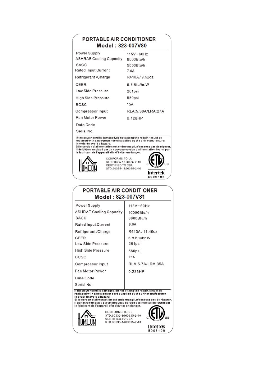
823-007V80/823-007V81
READ AND SAVE THESE INSTRUCTIONS
INcjg006_US

2
1. BEFORE YOU BEGIN
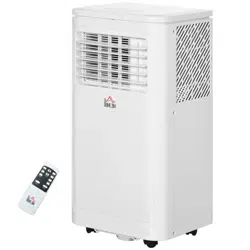
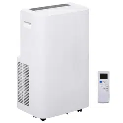
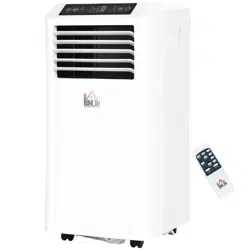
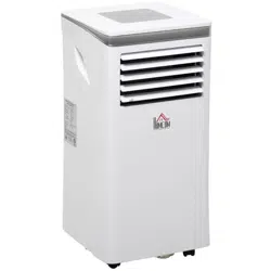
1.1 PRODUCT DESCRIPTION
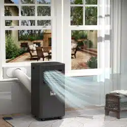
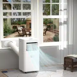
Our powerful portable air conditioners are great cooling solutions for
single rooms, creating a comfortable atmosphere in your space. It also
has ventilation and dehumidifying function for circulating air and removal
of moisture. They're self-contained systems that do not require any
permanent installation allowing you to move to the space in which it is
most needed. They're commonly used in kitchen, temporary-resided,
computer rooms, garages, and many other places where installation of
Air-conditioner Outdoor Unit is limited.
THE FOLLOWING SHOULD ALWAYS BE OBSERVED FOR SAFETY
This appliance is intended to be used by expert or trained users in
shops, in light industry and on farms, or for commercial use by lay
persons.
This appliance can be used by children aged from 8 years and
above and persons with reduced physical, sensory or mental
capabilities or lack of experience and knowledge if they have been
given supervision or instruction concerning use of the appliance in a
safe way and understand the hazards involved. Children shall not
play with the appliance. Cleaning and user maintenance shall not
be made by children without supervision.
The refrigerant loop is sealed. Only a qualified technician
should attempt to service!
Do not discharge the refrigerant into the atmosphere.
It collects first in low areas but can be circulated by the fans.
3
2. FOR YOUR SAFETY
Your safety is the most important thing we concerned!
2.1 OPERATIONAL PRECAUTIONS
WARNING- to reduce the risk of fire, electric shock or injury to
persons or property:
If the supply cord is damaged, it must be replaced by the
manufacturer, its service agent or similarly qualified persons in order to
avoid a hazard.
The appliance shall be disconnected from its power source during
service.
Always operate the unit from a power source of equal voltage,
frequency and rating as indicated on the product identification plate.
Always use a power outlet that is grounded.
Unplug the power cord when cleaning or when not in use.
Do not operate with wet hands. Prevent water from spilling onto the
unit.
Do not immerse or expose the unit to rain, moisture or any other
liquid.
Do not leave the unit running unattended. Do not tilt or turn over the
unit.
Do not unplug while the unit is operating.
WARNING
Please read this manual carefully and fully
understand before operating your appliance.

4
Do not unplug by pulling on the power cord.
Do not use an extension cord or an adapter plug.
Do not put objects on the unit.
Do not climb or sit on the unit.
Do not insert fingers or other objects into the air outlet.
Do not touch the air inlet or the aluminum fins of the unit.
Do not operate the unit if it is dropped, damaged or showing signs of
product malfunction.
Do not clean the appliance with any chemicals.
Ensure the unit is far away from fire, inflammable, or explosive
objects.
The unit shall be installed in accordance with national wiring
regulations.
Do not use means to accelerate the defrosting process or to clean,
other than those recommended by the manufacture.
The appliance shall be stored in a room without continuously operation
sources (for example: open flames, an operating gas appliance or an
operating electric heater).
The appliance shall be stored so as to prevent mechanical damage
from occurring.
Do not piece or burn, even after use.
Be aware that refrigerants may not contain an odour.
Compliance with national gas regulations shall be observed.
Keep any required ventilation openings clear of obstruction.
The appliance shall be stored in a well-ventilated area where the room
5
size corresponds to the room area as specified for operation.
WARNING
Any person who is involved with working on or breaking
into a refrigerant circuit should hold a current valid
certificate from an industry-accredited assessment
authority, which authorizes their competence to handle
refrigerants safely in accordance with an industry,
recognized assessment specification.
If you don't understand something or need help, please contact the dealer
services.
6
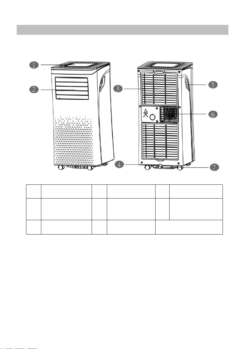
3. PRODUCT OVERVIEW
3.1 PRODUCT DIAGRAM
1
Control panel
4
Power cord
6
Air Exhaust
2
Air outlet with
adjustable
louver
5
Recessed
handle
7
Drain opening
with sealing plug
3
Air inlet with air
filter
Note: The appearance is only for reference. Please see the real product
for detailed information.

7
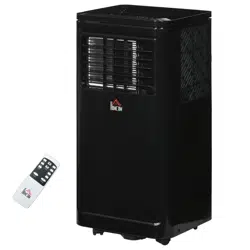
3.2 FEATURES
High Capacity in a compact size with cooling, heating,
dehumidifying and ventilating function.
Temperature setting and display
LED Digital display
Electronic control with built-in timer, sleep mode
Self-evaporating system for better efficient
Auto shut off when tank full
Automatic restart in the event of power outage
Auto defrosting function at low ambient temperatures
Remote control
2- speed fan
Casters for easy mobility
8
4. INSTALLATION
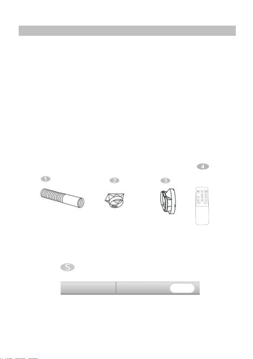
4.1 UNPACKING
Unpack the carton and take the appliance and accessories out.
Check the device after unpacking for any damage or scratches on
it.
Accessories:
1. Exhaust hose
2. Hose connector
3. Window kit adapter
4. Remote control
5. Window kit
9
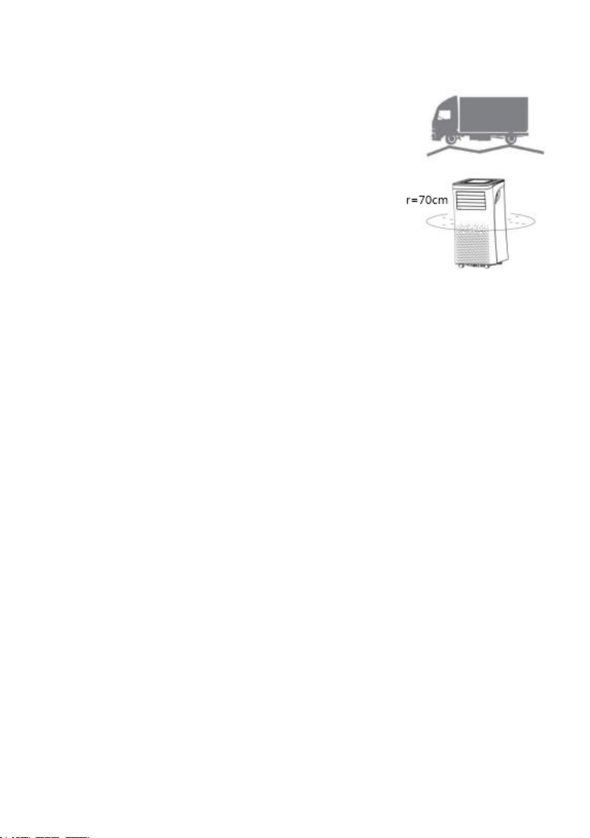
4.2 Choose your location
If tipped more than 45°, allow the
unit to set upright for at least 24
hours before start up.
Place the unit on a firm, level surface
in an area with at least 70cm of free
space around it to allow for proper air
circulation.
Do not operate in close proximity to
walls, curtains, or other objects that
may block air inlet and outlet. Keep
the air inlet and outlet free of obstacles.
Never install the unit where it could be subject to:
Heat sources such as radiators, heat registers, stoves or other
products that products that produce heat.
Direct sunlight
Mechanical vibration or shock
Excessive dust
Lack of ventilation, such as cabinet or bookcase
Uneven surface
10
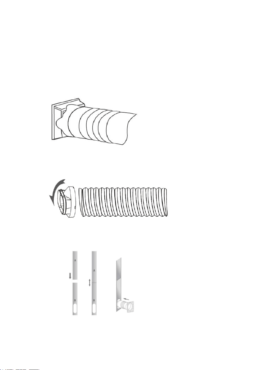
4.3 ATTACH THE EXHAUST HOSE
The air conditioner requires being vented outside so that the exhaust air
can escape the room which coming from the appliance contains waste heat
and moisture.
Do not replace or extend exhaust hose which will result in decreased
efficiency, even worse shut down the unit due to low backpressure.
Step 1: Connect the hose connector to one end of the exhaust hose.
Step 2: Connect the windows kit adapter to the other end of the
exhaust hose.
Step 3: Extend the adjustable window kit the length of your window.
Connect the exhaust hose to the window kit.
Step 4: Close your window to secure the kit in place. It needs to hold the
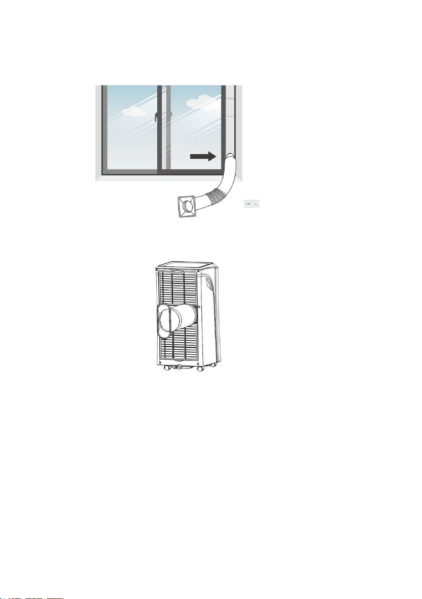
11
windows kit firmly in place, secure the window kit with duct tape if required. It is
recommended that the gap between the adapter and the sides of the window
should be sealed off for maximum efficiency.
Step 5: Attach the hose connector to the exhaust air outlet of unit.
12
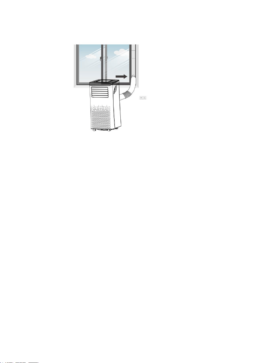
Step 6: Adjusting the length of the flexible exhaust hose, and avoid
bends in the hose. Then place AC near an electrical outlet.
Step 7: Adjust the louver at the air outlet, and then switch on the
unit.
13
5. OPERATION
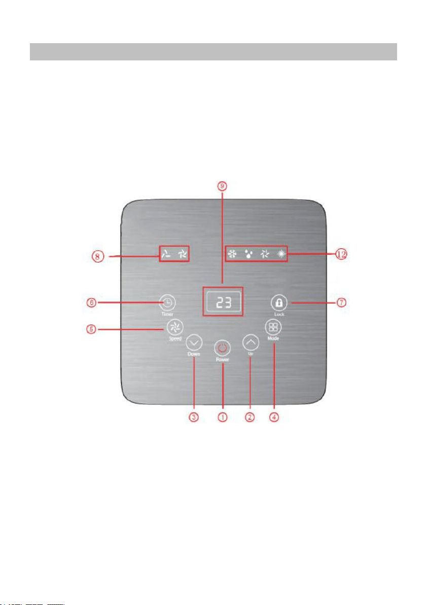
5.1 CONTROL PANEL AND DISPLAY
14
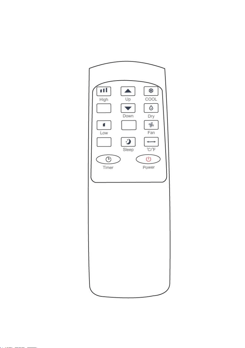
5.2 REMOTE CONTROL
15
5.3 FUNCTION KEYS AND INDICATORS
1.
POWER
Press to switch the machine on or off.
2.
ADD
Increasing the desired temperature or timer setting.
3.
MINUS
Decreasing the desired temperature(16℃~32℃)
or timer setting.
4.
MODE
Mode button Press to switch the operation mode
between cool, heat, fan, and dry.
5.
SPEED
Adjust the wind speed in high or low.
6.
TIMER
Sets a time for the unit to automatically start or stop.
7.
Lock
In this mode, the screen will be lock and all
functional button can’t press to adjust.
8.
SWING
Adjust the air flow direction vertically.
9.
Digital
Display
Displays timer setting and room temperature.
16
5.4 SETTINGS
5.4.1. Start-up and Shutdown
Press POWER to turn the unit on.
The unit runs in in FAN as default.
Press MODE button to select the desired operation mode.
Press POWER again to turn off the power.
5.4.2. Operation mode
The unit has five operation modes: Cool, heat, fan, dry,sleep.
A. Cooling your room
Select the cool mode to lower the temperature in your room.
Press MODE button repeatedly until the LED of COOL operation lights up.
Press ADD/MINUS button to adjust the temperature which is displayed
on the screen. The temperature can be set between 16℃ and 32℃.
Press SPEED button repeatedly until the desired fan speed indicator lights
up.
To control the direction of the air flow horizontally, please adjust the
inner louver by hand.
Note: The air conditioner stops if the room temperature is lower than
selected temperature.
B. Heating your room(Optional for Heating Function
Unit only)
Press MODE button repeatedly until the LED of HEAT operation lights up.
Press ADD/MINUS button to set the temperature higher than the room
temperature. The fan speed can also be set.
Note: The drainage hose should be attached to the unit for continuous
operating.
C. Ventilating your room
Press MODE button repeatedly until the LED of FAN operation lights up.
In ventilation mode the room air is circulated, but not cooled.
Press SPEED button repeatedly to select the fan speed as desired.

17
D. Drying your room
Press MODE button on the control panel or remote control, the LED of
DRY operation lights up. The fan speed is unable to select. User should
connect the hose to the drain outlet at the bottom of the unit.
Note: In this mode, the fan speed switches over to low speed and cannot
be selected.
E. Sleep mode
(
this function can only be used with a
remote control
)
The sleep mode can be activated when in cool mode and heat mode.
In cool mode :
After 1 hour the preset temperature is increased by 1 ℃, after another
hour the preset temperature will again be increased by 1 ℃.
In heat mode(Optional for Heating Function Unit only) :
After 1 hour the preset temperature is decreased by 1
℃
, after another
hour the preset temperature will again be decreased by 1 ℃.
Then the temperature is kept constant for 10 hours. And all the indicators dim
to dark. The fan speed may switch over to low speed for silent operating and
cannot be selected.
18
5.4.3. TIMER SETTING(1hour-24hours):
The timer has two ways of operation:
To turn off
(When power on)
To turn on
(When power off)
Cancel timer
5.4.4. Automatic Defrost
At low room temperatures, frost may buildup at the evaporator during operation.
The unit will automatically start defrosting and the POWER LED blinking. The
defrost control sequence is as follows:
A. When the unit operates in the cooling operation, drying operation, the
ambient temperature sensor senses the evaporator coil temperature is below
-1°C, after the compressor will stop operating for 10 minutes or the coil
temperature up to 7℃, the unit restart to cool operating mode.
B. When the unit operates in the heating operation, drying operation, once the
coil temperature sensor senses the temperature of the evaporator is below 40
℃ and the differential temperature between coil temperature and room
temperature is below 19℃ after the compressor operation for 20minutes, the
unit start defrosting for 5 minutes and the power indicator blinking.
5.4.5. Overload Protection
In the event of a power loss, to protect the compressor there is a 3-minute delay
until the compressor restarting.
Press Timer key to
turn on the timer
function.
Press Timer key to
turn on the timer
function.
Press ADD/MINUS
repeatedly to set the
delay OFF time.
Press ADD/MINUS
repeatedly to set the
delay ON time.
Press ADD/MINUES repeatedly until the LED shows ‘00’.
Note: when press POWER will also exit the timer setting.
19
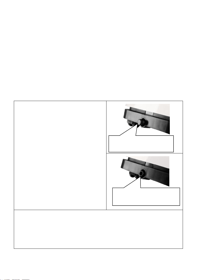
5.5 DRAINAGE
Self- evaporating system
The self-evaporating system uses the collected water to cool the
condenser coils for better efficient performance. It is no need to empty
the drainage tank in cooling operation except in heating operation,
drying operation and high humidity conditions. The condensate water
evaporates at the condenser and evacuated through the exhaust hose.
For continuous operation or unattended operating in drying and heating
operation, please connect the attached drain hose to the unit.
Condensate water can be automatically flow into a bucket or drain by
gravity.
Switch off the unit before
operating.
Remove the plug of the water
outlet opening, and keep it in
safe area.
Securely and properly connect
the drain hose and make sure it
is not kinked and clear of
obstruction.
Place the outlet of hose over a
drain or bucket and ensure that
water could freely flow out of the
unit.
Do not submerge the end of hose
into water; otherwise it can cause
"Air Lock" in the hose.
To avoid water spillage:
• As the negative pressure of condensate drain pan is large, tilt the
drain hose downward toward the floor. It is appropriate that the
degree of inclination should exceed 20 degrees.
•
Straighten the hose to avoid a trap existing in the hose.
Continuous drain hose
Remove the rubber
sealing plug.
20
6. CLEANING AND CARE
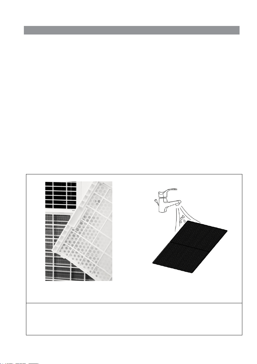
6.1. CLEANING THE AIR FILTER (every two weeks)
Dust collects on the filter and restricts the airflow. The restricted airflow
reduces the efficiency of the system and if it becomes blocked it can
cause damage to the unit.
The air filter requires regular cleaning. The air filter is removable for
easy cleaning. Do not operate the unit without an air filter, or the
evaporator may be contaminated.
1.
Press POWER button to switch off the unit and unplug the power cord.
2.
Remove the filter mesh from the unit.
3.
Use a vacuum cleaner to suck dust from the filter.
4.
Turn the filter over and rinse the air filter under running water. Let the
water run through the filter in the opposite direction of air flow. Set aside
and allow the filter to air dry completely before reinstalling.
Pic1. Switch off the unit and remove
the two air filters.
Pic2. Rinse the air filter under
running water.
Warning!!!
Do not touch the evaporator surface with bare-hand, or could cause
injury of your fingers.

21
6.2. CLEANING UP OF REFRIGERANT
General Measures:
1. Gas/vapor heavier than air. May accumulate in confined spaces,
particularly at or below ground level.
2. Eliminate every possible source of ignition.
3. Use appropriate personal protection equipment (PPE).
4. Evacuate unnecessary personnel, isolate, and ventilate area.
5. Do not get in eyes, on skin, or on clothing. Do not breathe vapors or
gas.
6. Prevent entry to sewers and public waters.
7. Stop the source of the release, if safe to do so. Consider the use of
water spray to disperse vapors.
8. Isolate the area until gas has dispersed. Ventilate and gas test area
before entering. Contact competent authorities after a spill.
22
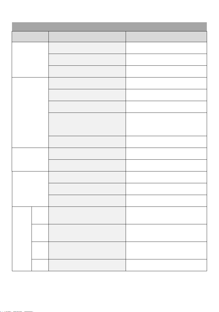
7. TROUBLESHOOTING
Symptom
Inspection
Solution
The unit is
not
operating.
Check the power
connection in securely.
Insert the power cord
securely into the wall Outlet.
Check if the water level
indicator lights up?
Empty the drain pan by
remove the rubber plug.
Check the room
temperature.
The range of operating
temperature is 5-35℃.
The unit
works with
reduced
capacity.
Check the air filter for dirt.
Clean the air filter as
necessary.
Check if the air duct is
blocked.
To clear the obstacle.
Check if the room door or
window is open.
Keep the door and windows
closed.
Check if the desired
operating mode is selected
and the temperature is
properly set.
Set the mode and
temperature at proper set-
point according the manual.
(refer to page16)
The exhaust hose is
detached.
Make sure the exhaust hose is
securely attached.
Water
Leakage
Overflow while moving the
unit.
Empty the water tank before
transport.
Check if the drain hose is
kinked or bends.
Straighten the hose to avoid a
trap existing.
Excessive
Noise
Check if the unit is securely
positioned.
Place the unit on horizontal
and firm ground.
Check if any loose,
vibrating parts.
Secure and tight the parts.
Noise sounds like water
flowing.
Noise comes from flowing
refrigerant. This is normal.
Error
Codes
E0
Communication faults
between main PCB and
display PCB.
Check the wire harness of the
display PCB for damage.
E1
Ambient temperature
sensor failure
Check connection or replace
it. To clean or replace the
temperature sensor.
E2
Coil temperature sensor
failures.
Check connection or replace
it. To clean or replace the
temperature sensor.
Ft
Condensate water high
level alarm.
Empty the drain pan by
removal the rubber plug.
23
8. DECOMMISSIONING
8.1. STORAGE
Long-Term Storage - If you will not be using the unit for an extended
period of time (more than a few weeks) it is best to clean the unit
and dry it out completely. Please store the unit per the following
steps:
8.2. DISPOSAL
WARNING!!!
Releasing refrigerant into atmosphere is strictly
forbidden!
Do not dispose of electrical appliances as
unsorted municipal waste, use separate
collection facilities. Contact your local
government for information regarding the
collection systems available. If electrical
appliances are disposed of in landfills or
dumps, hazardous substances can leak into
the groundwater and get into the food chain,
damaging your health and well-being.
1. Unplug the unit and remove exhaust hose and window kit store with the
unit.
2. Drain the remaining water from the unit.
3. Clean the filter and let the filter dry completely in a shaded area.
4. Collect the power cord at the water tank.
5. Re-install the filter at its position.
6. The unit must be kept in upright position when in storage.
7. Preserving the machine in ventilating, dry, non- corrosive gas and safe
place indoor.
ATTENTION:
The evaporator inside the machine has to be dried out before the unit is
packed to avoid component damage and molds. Unplug the unit and place
it in a dry open area for days to dry it out. Another way to dry the unit is
to set the humidity point more than 5% higher than the ambient humidity
to force the fan to dry the evaporator for a couple of hours.
24