2017 年 3 月 7 日
ARRAY 375XA&376XA ELECTRONIC LOAD SCPI PROGRAMMING MANUAL
A R R A Y
0 1
Array 375XA&376XA Electronic Load SCPI Programming Manual
Chapter I General Introduction ....................................................................................................................... 5
Purpose .................................................................................................................................................... 5
Supplied Documentation ......................................................................................................................... 5
Reference Documenatation ..................................................................................................................... 5
About the Manual .................................................................................................................................... 5
What You Should Already Know ............................................................................................................ 5
Chatper II Introduction to Programming ......................................................................................................... 6
2.1 GPIB Capabilities of the Electronic Load ................................................................................................. 6
GPIB Address .......................................................................................................................................... 6
2.2 RS-232 Capabilities of the Electronic Load .............................................................................................. 7
RS-232 Data Format ................................................................................................................................ 7
Baud Rate ................................................................................................................................................ 7
2.3 Introduction to SCPI .................................................................................................................................. 7
Conventions for this manual...................................................................................................................... 7
Types of SCPI Command .......................................................................................................................... 8
Multiple SCPI Commands in a Message ................................................................................................... 8
Moving among Subsystems ...................................................................................................................... 9
Including Common Commands ................................................................................................................. 9
Using Queries ............................................................................................................................................ 9
Types of SCPI Message ............................................................................................................................. 9
The Message Unit.................................................................................................................................... 10
Header ..................................................................................................................................................... 10
Query Indicator ....................................................................................................................................... 11
Command Separator ................................................................................................................................ 11
Root Specifier .......................................................................................................................................... 11
Terminator ............................................................................................................................................... 11
SCPI Data Format ................................................................................................................................... 11
Data Unit ................................................................................................................................................. 11
Character String Data Format.................................................................................................................. 12
SCPI Command Execution ...................................................................................................................... 12
Device Clear ............................................................................................................................................ 12
RS-232 Troubleshooting ......................................................................................................................... 13
SCPI Conformance Information .............................................................................................................. 13
SCPI Confirmed Commands ................................................................................................................... 13
Non-SCPI Commands ........................................................................................................................... 13
Chapter III Command Dictionary .................................................................................................................. 16
3.1 General Introduction ............................................................................................................................... 16
Syntax Forms ........................................................................................................................................ 16
Parameters ............................................................................................................................................. 16
Related Commands ............................................................................................................................... 16
2017 年 3 月 7 日
ARRAY 375XA&376XA ELECTRONIC LOAD SCPI PROGRAMMING MANUAL
A R R A Y
02
Presentation Order ................................................................................................................................. 16
Range of Programming Parameters ..................................................................................................... 16
3.2 IEEE488.2 Common Commands ............................................................................................................ 21
*CLS ..................................................................................................................................................... 21
*ESE ..................................................................................................................................................... 21
*ESE? ................................................................................................................................................... 22
*ESR? ................................................................................................................................................... 22
*IDN? ................................................................................................................................................... 22
*OPC .................................................................................................................................................... 22
*OPC? .................................................................................................................................................. 23
*PSC ..................................................................................................................................................... 23
*PSC? ................................................................................................................................................... 23
*RCL .................................................................................................................................................... 24
*RST ..................................................................................................................................................... 24
*SAV ..................................................................................................................................................... 24
*SRE ..................................................................................................................................................... 24
*SRE? ................................................................................................................................................... 24
*STB? ................................................................................................................................................... 25
*TRG .................................................................................................................................................... 25
*TST? ................................................................................................................................................... 25
*WAI ..................................................................................................................................................... 25
3.3 Subsystem Commands ....................................................................................................................... 25
3.3.1 Command Tree ..................................................................................................................................... 26
ABORt ................................................................................................................................................ 27
[SOURce:]MODE .............................................................................................................................. 27
[SOURce:]FUNC ............................................................................................................................... 28
3.3.2 Current Subsystem .......................................................................................................................... 28
[SOURce:]CURRent[:LEVel][:IMMediate][:AMPLitude] ........................................................... 29
[SOURce:]CURRent:LIMit............................................................................................................... 29
[SOURce:] CURRent:SLEWrate:NEGative ..................................................................................... 30
[SOURce:] CURRent:SLEWrate:POSitive ...................................................................................... 30
[SOURce:]CURRent:TLEVel ........................................................................................................... 30
[SOURce:]CURRent[:LEVel]:Trigger[:AMPLitude] ..................................................................... 31
[SOURce:]CURRent:PROTection [:LEVel] .................................................................................... 31
[SOURce:]CURRent:PROTection:STATe ....................................................................................... 31
[SOURce:]CURRent:PROTection:DELay ....................................................................................... 32
3.3.3 Voltage Subsystem ........................................................................................................................... 32
[SOURce:]VOLTage[:LEVel][:IMMediate][:AMPLitude] ............................................................. 33
[SOURce:]VOLTage:STARt ............................................................................................................. 33
[SOURce:]VOLTage:LIMit............................................................................................................... 33
[SOURce:] VOLTage:SLEWrate:NEGative ..................................................................................... 34
[SOURce:] VOLTage:SLEWrate:POSitive ...................................................................................... 34
[SOURce:] VOLTage:TLEVel .......................................................................................................... 34
[SOURce:] VOLTage [:LEVel]:Trigger[:AMPLitude] ................................................................... 35
2017 年 3 月 7 日
ARRAY 375XA&376XA ELECTRONIC LOAD SCPI PROGRAMMING MANUAL
A R R A Y
03
[SOURce:]VOLTage:PLUS:STAte ................................................................................................... 35
[SOURce:]VOLTage:PLUS:LIMit ................................................................................................... 35
3.3.4 Resistance Subsystem ......................................................................................................................... 36
[SOURce:]RESistance[:LEVel][:IMMediate][:AMPLitude] .......................................................... 36
[SOURce:]RESistance[:LEVel]:TLEVel.......................................................................................... 37
[SOURce:] RESistance:LIMit ........................................................................................................... 37
[SOURce:] RESistance:SLEWrate:NEGative .................................................................................. 38
[SOURce:] RESistance:SLEWrate:POSitive .................................................................................... 38
[SOURce:]RESistance[:LEVeI]:Trigger[:AMPLitude] ................................................................... 38
3.3.5 Power Subsystem ................................................................................................................................ 39
[SOURce:]POWer[:LEVeI] [:IMMediate][:AMPLitude] ............................................................... 39
[SOURce:] POWer:LIMit ................................................................................................................. 39
[SOURce:] POWer:SLEWrate:NEGative ........................................................................................ 40
[SOURce:] POWer:SLEWrate:POSitive .......................................................................................... 40
[SOURce:] POWer:TLEVel .............................................................................................................. 40
[SOURce:]POWer[:LEVeI]:Trigger[:AMPLitude] ......................................................................... 41
3.3.6 List Subsystem .................................................................................................................................... 41
[SOURce:]LIST[:STATe] .................................................................................................................. 42
[SOURce:]LIST:NUMBer ................................................................................................................. 42
[SOURce:]LIST:MEMO ................................................................................................................... 42
[SOURce:]LIST:STEPs ..................................................................................................................... 43
[SOURce:]LIST:STEP:EDIT ........................................................................................................... 43
[SOURce:]LIST:COUNt ................................................................................................................... 43
[SOURce:]LIST:CHAin .................................................................................................................... 43
[SOURce:]LIST:CLEar ..................................................................................................................... 44
[SOURce:]LIST:SAVE ...................................................................................................................... 44
3.3.7 Transient Subsystem .......................................................................................................................... 44
[SOURce:]TRANsient:MODE .......................................................................................................... 45
[SOURce:]TRANsient:LTIMe .......................................................................................................... 45
[SOURce:]TRANsient:HTIMe ........................................................................................................ .46
[SOURce:]TRANsient:RTIMe .......................................................................................................... 46
[SOURce:]TRANsient:FTIMe .......................................................................................................... 46
3.3.8 Input Subsystem ................................................................................................................................. 47
INPut[:STATe] ................................................................................................................................... 47
INPut:PROTection:CLEar ................................................................................................................ 47
3.3.9 MEASure ............................................................................................................................................. 47
MEASure[:SCALar]:CURRent[:DC]? ............................................................................................. 48
MEASure[:SCALar]:VOLTage[:DC]? ............................................................................................. 48
MEASure[:SCALar]:RESistance[:DC]? ........................................................................................... 48
MEASure[:SCALar]:POWer[:DC]? ................................................................................................. 48
3.3.10 Trigger Subsystem ............................................................................................................................ 49
TRIG[:IMMediate] ............................................................................................................................ 49
TRIG:SOURce ................................................................................................................................... 50
TRIG:FUNCtion ................................................................................................................................ 50
2017 年 3 月 7 日
ARRAY 375XA&376XA ELECTRONIC LOAD SCPI PROGRAMMING MANUAL
A R R A Y
04
INIT[:IMMediate] .............................................................................................................................. 51
INIT:CONTinuous ............................................................................................................................. 51
TRIGger:DELay ................................................................................................................................ 51
3.3.11 Status Subsystem .............................................................................................................................. 52
STATus:QUEStionable[:EVENt]? .................................................................................................... 52
STATus:QUEStionable:ENABle ....................................................................................................... 52
STATus:QUEStionable:ENABle? ..................................................................................................... 52
STATus:QUEStionable:CONDition? ................................................................................................ 53
STATus:OPERation[:EVENt]? ......................................................................................................... 53
STATus:OPERation:ENABle ............................................................................................................ 53
STATus:OPERation:CONDition? ..................................................................................................... 53
3.3.12 System Subsystem ............................................................................................................................ 54
SYSTem:ERRor[:NEXT]? ................................................................................................................ 54
SYSTem:VERSion? ........................................................................................................................... 54
SYSTem:LOCal ................................................................................................................................. 54
SYSTem:REMote .............................................................................................................................. 55
SYSTem:REMote .............................................................................................................................. 55
SYSTem:RWLock ............................................................................................................................. 55
Chapter IV Register Status Report ................................................................................................................ 56
Common Register Model ...................................................................................................................... 59
Questionable Status Register ................................................................................................................. 59
Output Queue ........................................................................................................................................ 59
Standard Event Register ........................................................................................................................ 59
Operation Status Register .................................................................................................................... 60
Status Byte Register .............................................................................................................................. 60
Service Request Enable Register ........................................................................................................... 60
Appendix Error Message ............................................................................................................................... 61
2017 年 3 月 7 日
ARRAY 375XA&376XA ELECTRONIC LOAD SCPI PROGRAMMING MANUAL
A R R A Y
0 5
Chapter I General Introduction
Purpose
The purpose of this manual is to help you remotely control your ARRAY 375XA series electronic load from a
controller using SCPI programming language with SCPI commands. Before the remote control operation, it is
assumed you have completed the following preparations:
1. The electronic load has been installed properly and is operated normally from the front panel;
2. The controller has been connected to the USB, GPIB or the RS-232 interface of the electronic load and the
related parameters for the interface have been set.
Notes: The interface parameters such as GPIB Address, Baud Rate and Data bit of RS-232 must be set from
the front panel of the electronic load. Please refer to the 375XA&376XA User’s Manual for details.
Supplied Documentation
Every Array 375X&376X series electronic load comes with the following electronic load documentations:
User’s Manual It instructs how to install and handle basic operations, including the local operation from the
front panel. Be sure to read it first.
SCPI Programming Manual It explains how to use SCPI commands to remotely control Array 375XA series
electronic load from a controller using SCPI programming language.
Reference Documentation
The following documents facilitate you to get a better understanding of GPIB interface and SCPI programming:
ANSI/IEEE Std. 488.1-1987 IEEE Standard Digital Interface for Programmable Instrumentation.
Standard Commands for Programmable Instruments VERSION 1999.0.
About this Manual
This manual contains the information concerns programming Array 375X&376X series electronic load.
Chapter I Introduction to this manual
Chapter II The basics about the message structure, syntax and the data format for SCPI commands
Chapter III Language dictionary
Chapter IV Status reporting
Appendix Error Messages
What You Should Already Know
This manual does not assume that you have already known SCPI very well or you are a programmer. It is supposed
that you have already known the follows:
● The basics of GPIB interface;
● How to send and receive ASCII data between a computer and an instrument over GPIB USB or RS-232 interface
● How to input and output the SCPI statements as ASCII strings with the using programming language
● The basic operations of the electronic load introduced in the Users Manual
2017 年 3 月 7 日
ARRAY 375XA&376XA ELECTRONIC LOAD SCPI PROGRAMMING MANUAL
A R R A Y
06
Chapter II Introduction to Programming
2.1 GPIB Capabilities of the Electronic Load
GPIB interface is optional for the electronic load and it must be set from the front panel. Press I/Oconfig Key to
enter the set menu, and then set in the Interface option. The Interface option is saved in nonvolatile memory.
Except for the parameter setting of the communication port, all functions of the electronic load can be programmed
over the GPIB interface. When GPIB interface is selected, other interfaces are needed to be chosen to be closed.
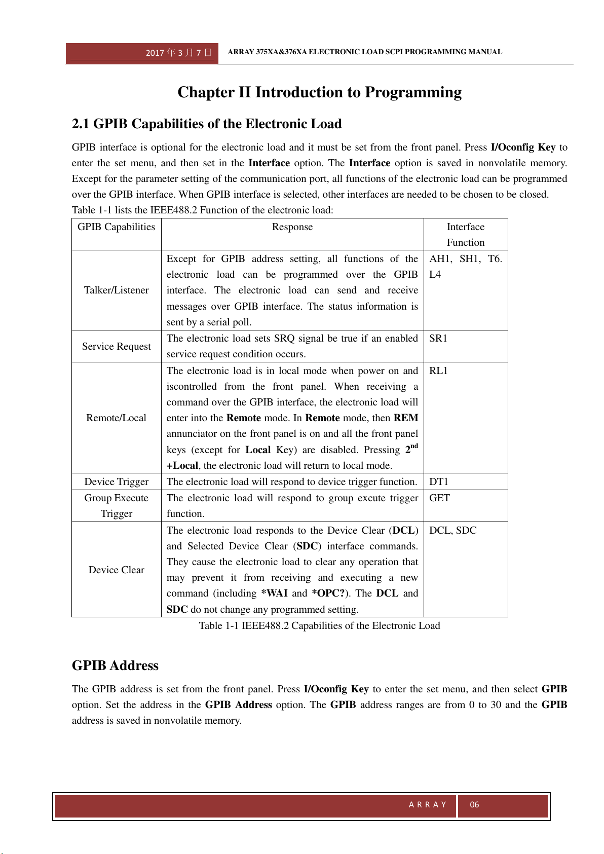
Table 1-1 lists the IEEE488.2 Function of the electronic load:
GPIB Capabilities
Response
Interface
Function
Talker/Listener
Except for GPIB address setting, all functions of the
electronic load can be programmed over the GPIB
interface. The electronic load can send and receive
messages over GPIB interface. The status information is
sent by a serial poll.
AH1, SH1, T6.
L4
Service Request
The electronic load sets SRQ signal be true if an enabled
service request condition occurs.
SR1
Remote/Local
The electronic load is in local mode when power on and
iscontrolled from the front panel. When receiving a
command over the GPIB interface, the electronic load will
enter into the Remote mode. In Remote mode, then REM
annunciator on the front panel is on and all the front panel
keys (except for Local Key) are disabled. Pressing 2
nd
+Local, the electronic load will return to local mode.
RL1
Device Trigger
The electronic load will respond to device trigger function.
DT1
Group Execute
Trigger
The electronic load will respond to group excute trigger
function.
GET
Device Clear
The electronic load responds to the Device Clear (DCL)
and Selected Device Clear (SDC) interface commands.
They cause the electronic load to clear any operation that
may prevent it from receiving and executing a new
command (including *WAI and *OPC?). The DCL and
SDC do not change any programmed setting.
DCL, SDC
Table 1-1 IEEE488.2 Capabilities of the Electronic Load
GPIB Address
The GPIB address is set from the front panel. Press I/Oconfig Key to enter the set menu, and then select GPIB
option. Set the address in the GPIB Address option. The GPIB address ranges are from 0 to 30 and the GPIB
address is saved in nonvolatile memory.
2017 年 3 月 7 日
ARRAY 375XA&376XA ELECTRONIC LOAD SCPI PROGRAMMING MANUAL
A R R A Y
07
USB
The USB interface of the Electronic Load compatible with IEEE488.2 protocol
2.2 RS-232 Capabilities of the Electronic Load
The electronic load is equipped with RS-232 interface, which must be set from the front panel. Press I/Oconfig Key
to enter the set menu, and then select COM option to set. The communication interface option is saved in
nonvolatile memory. All SCPI commands can be programmed over the RS-232 interface. When RS-232 interface
is selected, the other interfaces are needed to be chosen to be closed.
EIA RS-232 Standard defines how Data Terminal Equipment (DTE) and Data Communications Equipment (DCE)
interconnect with each other. The electronic load, as a kind of DTE, can be connected to other DTE (e.g. a PC COM
Port) with a null modem cable.
Array 375XA series Electronic Load can program RS-232 interface in MENU. Please make sure the settings of the
interlinked equipments are matched, or you will fail to connect them properly.
Notes: If RS-232 interface is not selected, the related option of RS-232 interface will not be found in the set
menu.
RS-232 Data Format
RS-232 data is composed of one start bit, one or two stop bits and seven or eight data bits. For party check, you can
select among odd, even and none. All parameters are set in MENU.
Data Bit: Select seven or eight data bits
Stop Bit: Select one or two stop bits
Party Check: None
Even
Odd
The data format is saved in nonvolatile memory.
Baud Rate
Baud Rate can be set via Baud Rate option in MENU. Its parameter is saved in nonvolatile memory. The
electronic load supports the following baud rates: 2400, 4800, 9600, 19200, 38400, 57600 and 115200. The default
baud rate is 9600bps.
2.3 Introduction to SCPI
SCPI (Standard Commands for Programmable Instruments) is a programming language controlling instrument
over GPIB USB or RS-232 interface. In IEEE488.2, SCPI is layered on top of the hardware-portion. The same
SCPI commands and parameters control the same functions for different categories of instruments.
Conventions for This Manual
For a convenient description, the subsequent symbols are defined as follows:
Angle Brackets < > Items within angle brackets are parameter type in abbreviations.
2017 年 3 月 7 日
ARRAY 375XA&376XA ELECTRONIC LOAD SCPI PROGRAMMING MANUAL
A R R A Y
08
Square Brackets [ ] Items within square brackets can be omitted.
Braces { } Parameters within braces can be repeated zero or more times.
Verticle Bar | Alternative parameters is separated by a vertical bar.
Types of SCPI Commands
SCPI has two types of commands: common commands and subsystem commands.
Common commands: Common commands are the general term for a catagery of commands. They, defined by
IEEE488.2 Standard, are commonly not related to a specific operation but to controlling overall load functions, such
as rest, synchronization, status setting, query and so on functions. Every common command is composed by “*” and
a three-letter mnemonic, such as: *RST, *IDN?, *SAV and so on.
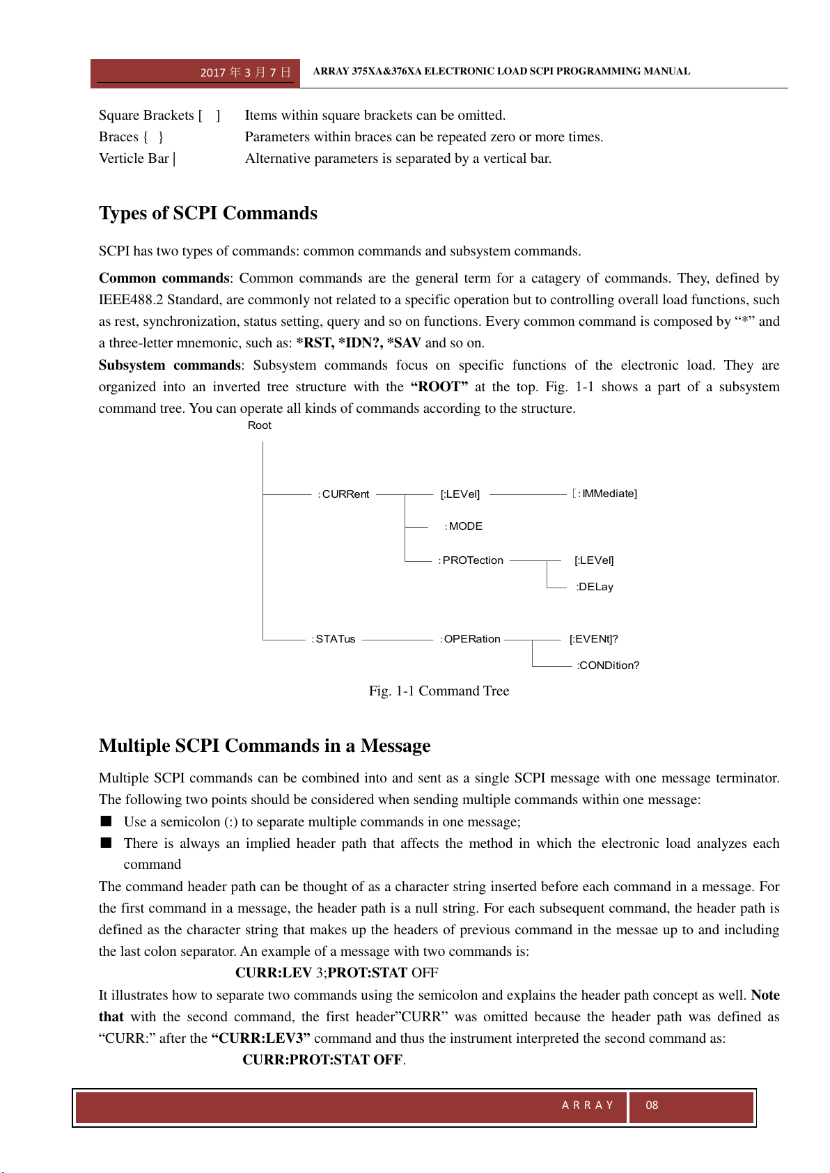
Subsystem commands: Subsystem commands focus on specific functions of the electronic load. They are
organized into an inverted tree structure with the “ROOT” at the top. Fig. 1-1 shows a part of a subsystem
command tree. You can operate all kinds of commands according to the structure.
Fig. 1-1 Command Tree
Multiple SCPI Commands in a Message
Multiple SCPI commands can be combined into and sent as a single SCPI message with one message terminator.
The following two points should be considered when sending multiple commands within one message:
■ Use a semicolon (:) to separate multiple commands in one message;
■ There is always an implied header path that affects the method in which the electronic load analyzes each
command
The command header path can be thought of as a character string inserted before each command in a message. For
the first command in a message, the header path is a null string. For each subsequent command, the header path is
defined as the character string that makes up the headers of previous command in the messae up to and including
the last colon separator. An example of a message with two commands is:
CURR:LEV 3;PROT:STAT OFF
It illustrates how to separate two commands using the semicolon and explains the header path concept as well. Note
that with the second command, the first header”CURR” was omitted because the header path was defined as
“CURR:” after the “CURR:LEV3” command and thus the instrument interpreted the second command as:
CURR:PROT:STAT OFF.
Root
:CURRent
[:LEVel]
[:IMMediate]
:MODE
:PROTection
:STATus
:OPERation
[:LEVel]
:DELay
[:EVENt]?
:CONDition?
2017 年 3 月 7 日
ARRAY 375XA&376XA ELECTRONIC LOAD SCPI PROGRAMMING MANUAL
A R R A Y
09
In fact, it would have generated a syntactic error to incluse”CURR:” improperly in the second command, since the
command after being combined with the header path would become:
CURR:CURR:PROT:STAT OFF
that is incorrect.
Moving among Subsystems
In order to combine commands from different subsystems, it is needed to reset the header path to a null string
within a message. You can do this by beginning the command with a colon (:), a root specifier, to discard any
preceding header path. For example, you can clear the output protection and check the status of the operation
condition resister in one message by using a root sepcifier as follows:
INPut:PROTection:CLEar;:STATus:OPERation:CONDition?
The following message shows how to combine commands from different subsystems as well as within the same
subsystem:
VOLTage:LEVel 20;TRIGger 28; :CURRent:LEVel 3;TRIGger 5
Including Common Commands
Common commands can be combined with subsystem commands in a message. Treat the common command as a
message unit by separating it from other commands with a semicolon (the message unit separator). Common
commands do not affect the header path and can be inserted anywhere in a message.
For Example: VOLTage:Trigger 17.5;:INITialize;*TRG
INPut OFF;*RCL 2;INPut ON
Using Queries
Using queries has the following concerns:
● Sepcify proper numbers of variables for the data returned by queries.
● Read all the returned data of a query before sending another command to the electronic load. Otherwise a
Query Interrupted Error will occur and the unreturned data will be lost.
Types of SCPI Message
There are two types of SCPI messages: program and response.
● A program message consists of one or more properly formatted SCPI commands sent from the controller to the
electronic load. The message, which may be sent at any time, requests the electronic load to perform some
operation.
● A response message consists of data in a specific SCPI format sent from the electronic load to the controller.
The electronic load sends the response message only when receiving a program message called a "query."
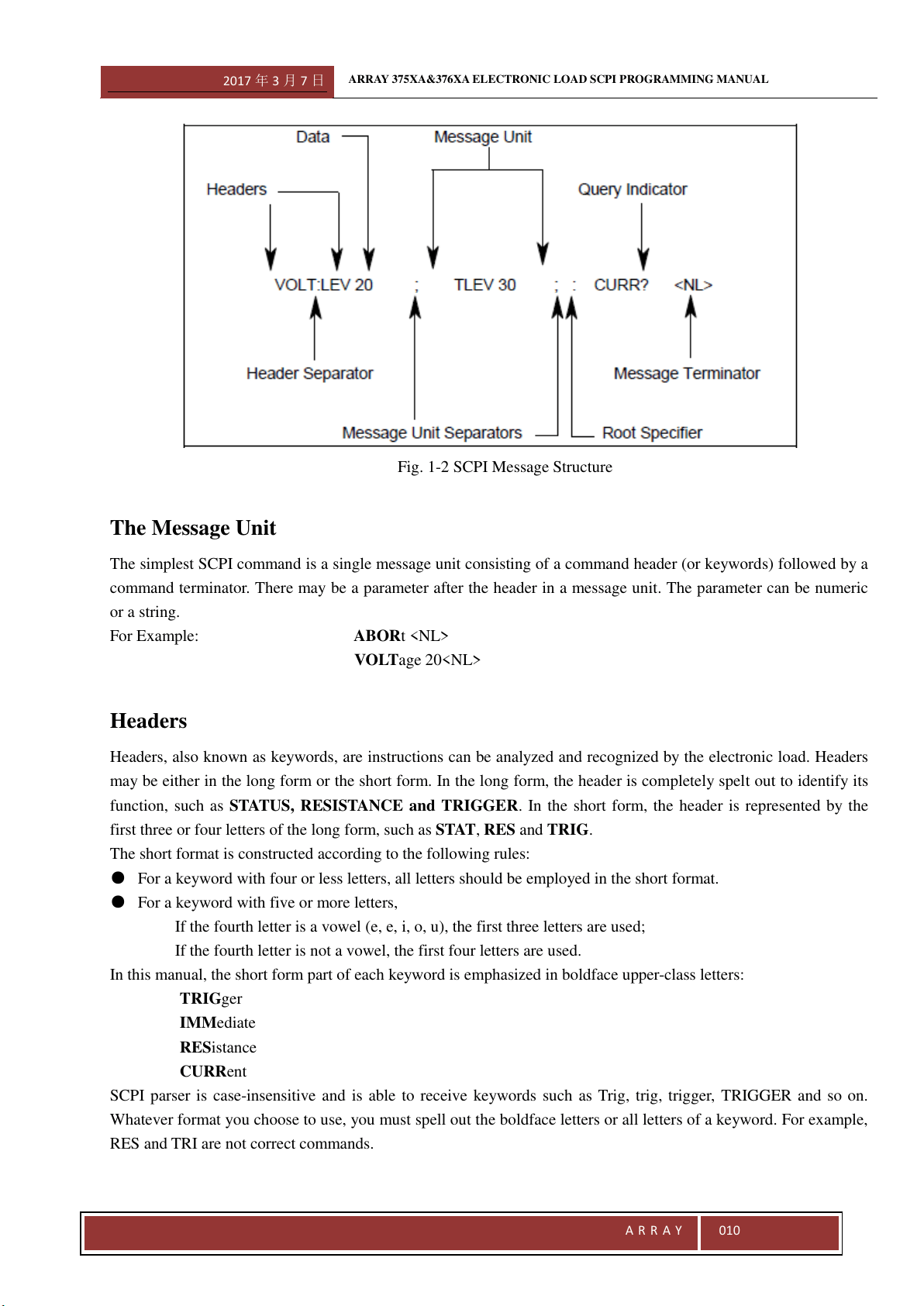
SCPI message structure is showed as follows:
2017 年 3 月 7 日
ARRAY 375XA&376XA ELECTRONIC LOAD SCPI PROGRAMMING MANUAL
A R R A Y
010
Fig. 1-2 SCPI Message Structure
The Message Unit
The simplest SCPI command is a single message unit consisting of a command header (or keywords) followed by a
command terminator. There may be a parameter after the header in a message unit. The parameter can be numeric
or a string.
For Example: ABORt <NL>
VOLTage 20<NL>
Headers
Headers, also known as keywords, are instructions can be analyzed and recognized by the electronic load. Headers
may be either in the long form or the short form. In the long form, the header is completely spelt out to identify its
function, such as STATUS, RESISTANCE and TRIGGER. In the short form, the header is represented by the
first three or four letters of the long form, such as STAT, RES and TRIG.
The short format is constructed according to the following rules:
● For a keyword with four or less letters, all letters should be employed in the short format.
● For a keyword with five or more letters,
If the fourth letter is a vowel (e, e, i, o, u), the first three letters are used;
If the fourth letter is not a vowel, the first four letters are used.
In this manual, the short form part of each keyword is emphasized in boldface upper-class letters:
TRIGger
IMMediate
RESistance
CURRent
SCPI parser is case-insensitive and is able to receive keywords such as Trig, trig, trigger, TRIGGER and so on.
Whatever format you choose to use, you must spell out the boldface letters or all letters of a keyword. For example,
RES and TRI are not correct commands.
2017 年 3 月 7 日
ARRAY 375XA&376XA ELECTRONIC LOAD SCPI PROGRAMMING MANUAL
A R R A Y
011
Query Indicator
Following a header with a question mark turns it into a query (VOLTage?, VOLTage:TRIGger?). If a query
command contains a parameter, then place the query indicator (?) at the end of the last header (VOLTage:TRIGger?
MAX).
Command Separator
When two or more commands are combined into a compound command, separate the commands with a semicolon
(;):
STATus:OPERation?;QUEStionable?.
Root Specifier
When it precedes the first header of a message unit, the colon becomes the root specifier. It informs the command
parser that this is the root or the top node of the command tree.
Terminator
The SCPI messages sent to the electronic load must be terminated by a <newline> character. IEEEE-488EOI can
function as a <newline> character to terminate a command string. The <Carriage Return> character followed by a
<newline> character is also acceptable for a terminator. The termination of a message always resets the header path
for the current SCPI statement to its root.
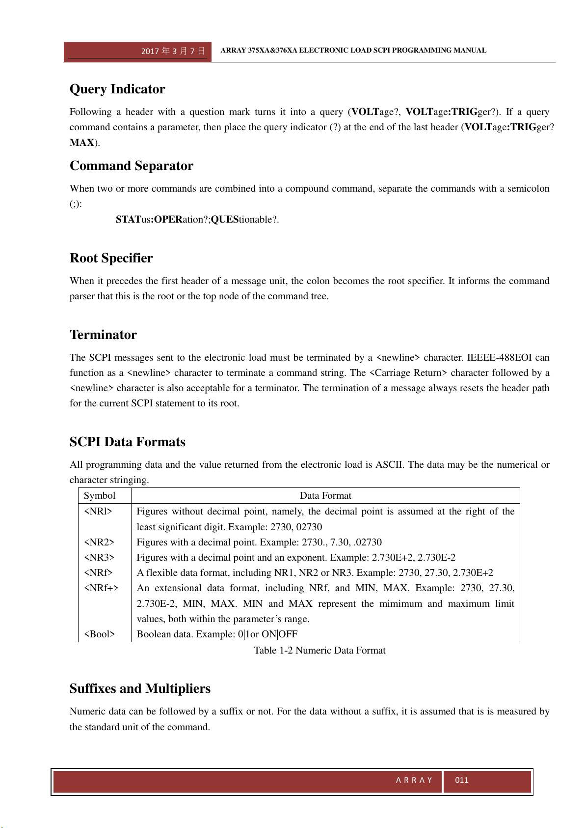
SCPI Data Formats
All programming data and the value returned from the electronic load is ASCII. The data may be the numerical or
character stringing.
Symbol
Data Format
<NRl>
<NR2>
<NR3>
<NRf>
<NRf+>
<Bool>
Figures without decimal point, namely, the decimal point is assumed at the right of the
least significant digit. Example: 2730, 02730
Figures with a decimal point. Example: 2730., 7.30, .02730
Figures with a decimal point and an exponent. Example: 2.730E+2, 2.730E-2
A flexible data format, including NR1, NR2 or NR3. Example: 2730, 27.30, 2.730E+2
An extensional data format, including NRf, and MIN, MAX. Example: 2730, 27.30,
2.730E-2, MIN, MAX. MIN and MAX represent the mimimum and maximum limit
values, both within the parameter’s range.
Boolean data. Example: 0|1or ON|OFF
Table 1-2 Numeric Data Format
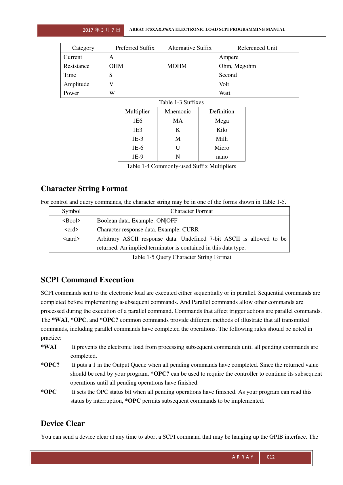
Suffixes and Multipliers
Numeric data can be followed by a suffix or not. For the data without a suffix, it is assumed that is is measured by
the standard unit of the command.
2017 年 3 月 7 日
ARRAY 375XA&376XA ELECTRONIC LOAD SCPI PROGRAMMING MANUAL
A R R A Y
012
Category
Preferred Suffix
Alternative Suffix
Referenced Unit
Current
Resistance
Time
Amplitude
Power
A
OHM
S
V
W
MOHM
Ampere
Ohm, Megohm
Second
Volt
Watt
Table 1-3 Suffixes
Multiplier
Mnemonic
Definition
1E6
1E3
1E-3
1E-6
1E-9
MA
K
M
U
N
Mega
Kilo
Milli
Micro
nano
Table 1-4 Commonly-used Suffix Multipliers
Character String Format
For control and query commands, the character string may be in one of the forms shown in Table 1-5.
Symbol
Character Format
<Bool>
<crd>
Boolean data. Example: ON|OFF
Character response data. Example: CURR
<aard>
Arbitrary ASCII response data. Undefined 7-bit ASCII is allowed to be
returned. An implied terminator is contained in this data type.
Table 1-5 Query Character String Format
SCPI Command Execution
SCPI commands sent to the electronic load are executed either sequentially or in parallel. Sequential commands are
completed before implementing asubsequent commands. And Parallel commands allow other commands are
processed during the execution of a parallel command. Commands that affect trigger actions are parallel commands.
The *WAI, *OPC, and *OPC? common commands provide different methods of illustrate that all transmitted
commands, including parallel commands have completed the operations. The following rules should be noted in
practice:
*WAI It prevents the electronic load from processing subsequent commands until all pending commands are
completed.
*OPC? It puts a 1 in the Output Queue when all pending commands have completed. Since the returned value
should be read by your program, *OPC? can be used to require the controller to continue its subsequent
operations until all pending operations have finished.
*OPC It sets the OPC status bit when all pending operations have finished. As your program can read this
status by interruption, *OPC permits subsequent commands to be implemented.
Device Clear
You can send a device clear at any time to abort a SCPI command that may be hanging up the GPIB interface. The
2017 年 3 月 7 日
ARRAY 375XA&376XA ELECTRONIC LOAD SCPI PROGRAMMING MANUAL
A R R A Y
013
status registers, the error queue, and all configuration states remain unchanged when a device clear message is
received. Device clear executes the following operations:
● The input and output buffers of the electronic load are cleared.
● The electronic load is ready to receive a new command string.
RS232 Troubleshooting
If you encounter problems communicating over RS-232 interface, please check the fllowing items:
● The computer must configure the same rate, number of data bits, number of stop bits, parity check options.
● Use correct interface cables or adapter. Please note that even though the cable has the suitable connector, the inner
wiring may be incorrect.
● The interface cables must be connected to the correct serial port on your computer (COM1, COM2…).
SCPI Conformance Information
SCPI conformed commands
The electronic load conforms to SCPI Version 1999.0.
ABOR
INIT[:IMM]
INIT:CONT
TRIG [:IMM]
TRIG:SOUR
[SOUR:]POW[:LEV][:IMM][:AMPL]
[SOUR:]POW[:LEV]:TRIG[:AMPL]
[SOUR:]CURR[:LEV][:IMM][:AMPL]
[SOUR:]CURR[:LEV]:TRIG[:AMPL]
[SOUR:]VOLT[:LEV][:IMM][:AMPL]
[SOUR:]VOLT[:LEV]:TRIG[:AMPL]
[SOUR:]RES[:LEV][:IMM][: AMPL]
[SOUR:]RES[:LEV]:TRIG[:AMPL]
[SOUR:]CURR:PROT[:LEV]
[SOUR:]CURR:PROT:STAT
STAT:QUES[:EVEN]
STAT:QUES:COND
STAT:QUES:ENAB
SYST:ERR
SYST:VER
NON-SCPI Commands
Although the following commands are not standard SCPI commands, their command syntax and parameter form are
defined on the SCPI Version 1999.0 basic.
[SOURce:]CURRent:LIMit [SOURce:]CURRent:PROTection:DELay
2017 年 3 月 7 日
ARRAY 375XA&376XA ELECTRONIC LOAD SCPI PROGRAMMING MANUAL
A R R A Y
014
[SOURce:]CURRent:LIMit
[SOURce:] CURRent:SLEWrate:NEGative
[SOURce:] CURRent:SLEWrate:POSitive
[SOURce:]CURRent:TLEVel
[SOUR:]MODE
[SOURce:]FUNCtion
[SOURce:]RESistance:LIMit
[SOURce:]RESistance:SLEWrate:NEGative
[SOURce:]RESistance:SLEWrate:POSitive
[SOURce:]RESistance:TLEVel
[SOURce:]VOLTage:STARt
[SOURce:]VOLTage:LIMit
[SOURce:]VOLTage:SLEWrate:NEGative
[SOURce:]VOLTage:SLEWrate:POSitive
[SOURce:]VOLTage:TLEVel
[SOURce:]VOLTage:PLUS:STAte
[SOURce:]VOLTage:PLUS:STAte?
[SOURce:]POWer:LIMit
[SOURce:]POWer:SLEWrate:NEGative
[SOURce:]POWer:SLEWrate:POSitive
[SOURce:]POWer:TLEVel
[SOURce:]TRANsient:MODE
[SOURce:]TRANsient:LTIMe
[SOURce:]TRANsient:HTIMe
[SOURce:]TRANsient:RTIMe
[SOURce:]TRANsient:FTIMe
MEAS[:SCAL]:VOLT[:DC]
MEAS [:SCAL]:CURR[:DC]
MEAS [:SCAL]:RES[:DC]
MEAS [:SCAL]:POW[:DC]
SYST:LOCA
SYST:REM
INP:PROT:CLE
[SOUR:] TRAN:MODE
[SOUR:] TRAN:LTIM
[SOUR:] TRAN:HTIM
[SOUR:] TRAN:RTIM
[SOUR:] TRAN:FTIM
[SOURce:]LIST[:STATe]
[SOURce:]LIST:NUMBer
[SOURce:]LIST:MEMO
[SOURce:]LIST:COUNt
[SOURce:]LIST:CHAin
[SOURce:]LIST:STEPs
2017 年 3 月 7 日
ARRAY 375XA&376XA ELECTRONIC LOAD SCPI PROGRAMMING MANUAL
A R R A Y
015
[SOURce:]LIST:CLEar
[SOURce:]LIST:SAVE
[SOURce:]LIST:STEP:EDIT
2017 年 3 月 7 日
ARRAY 375XA&376XA ELECTRONIC LOAD SCPI PROGRAMMING MANUAL
A R R A Y
016
Chapter III Language Dictionary
3.1 General Introduction
This chapter will give you a thorough introduction to the syntax and parameters for IEEE488.2 common commands
and SCPI commands used by Array 375X&376X Series Electronic Load. Suppose you have got a good
understanding of the material in Chapter II and the 375XA&376X series User’s Manual.
Syntax Format
Long forms are used to introduce command syntax, but only short forms appear in all examples. Using the long
form makes your program easy to understand.
Parameters
Most commands come with a parameter and most queries return a parameter. The parameter range is determined by
the model of the electronic load. Since the parameters for the smaple program in this manual are based on Array
3751A electronic load and the program itself is common for any 375X&376X electronic load, the associated
parameters should be reset for other models. Parameters for all models are listed in the following table.
Related Commands
Commands and queries related to the original command, which are either directly related to the original command
by function or facilitate you to further understand original command.
Presentation Order
This Chapter contains all commands and queries for 375X&376X series electronic load, which are arranged in the
following orders:
·IEEE488.2 common command, listed in alphabetical order;
·Root Level Commands, A-Z listing, including:
·Single Commands
·Subsystem:The single subsystem commands are arranged alphabetically under the subsystem.
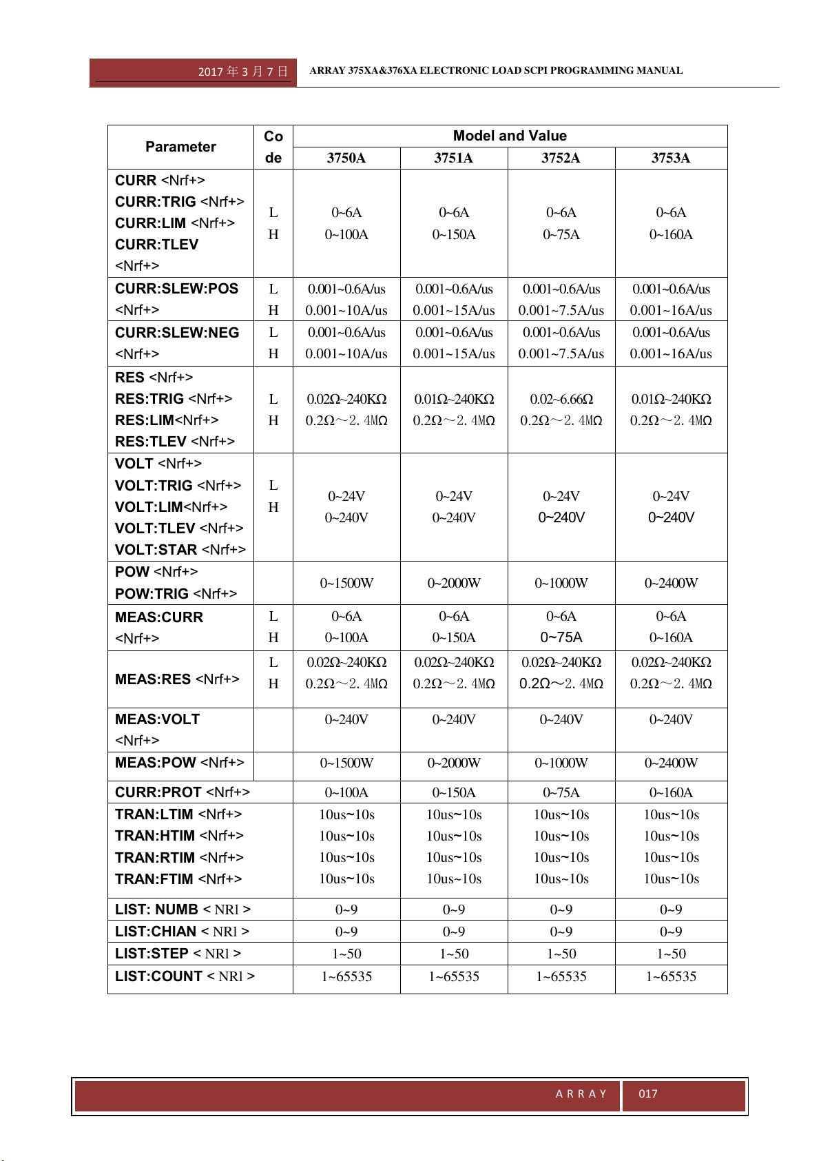
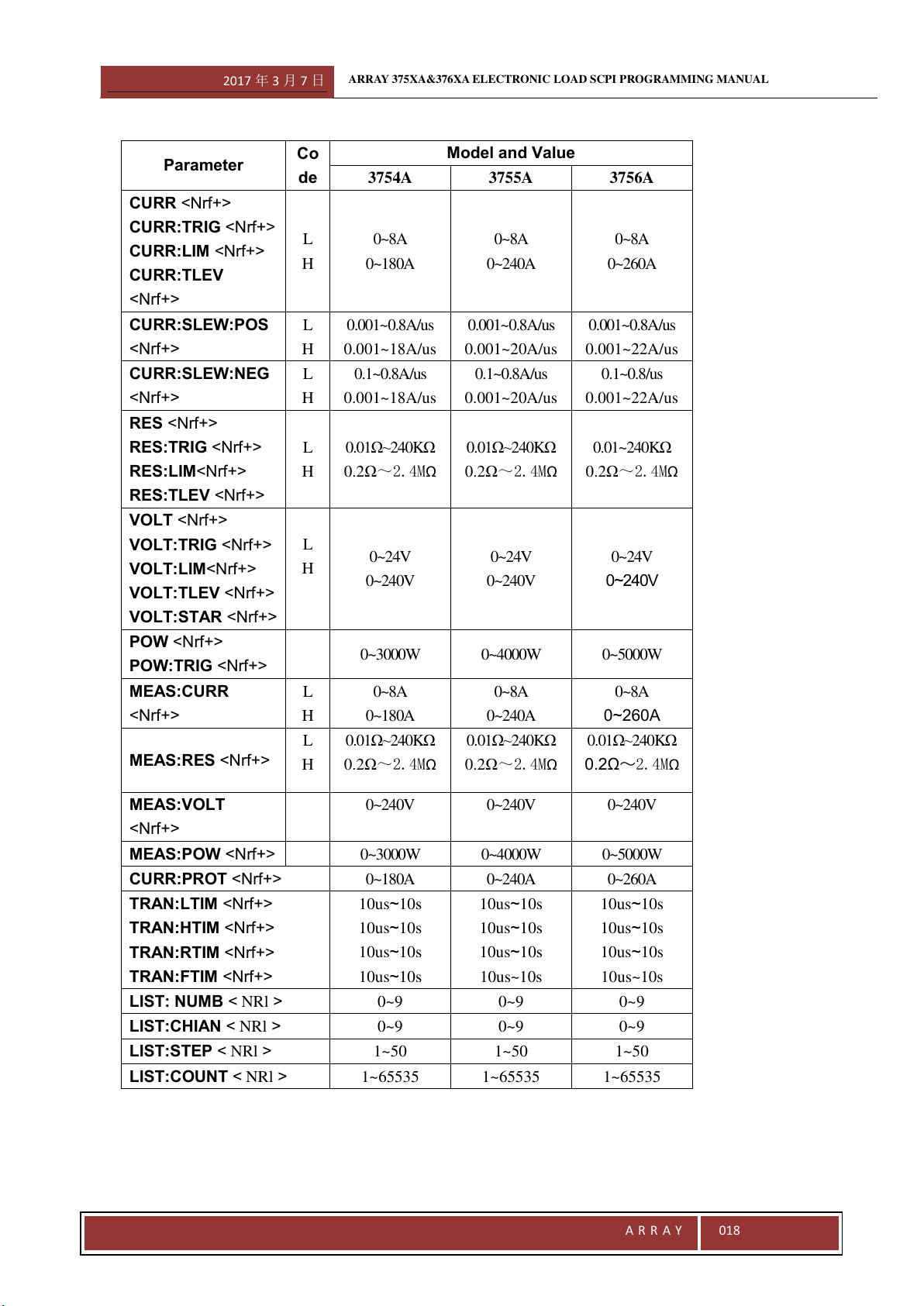
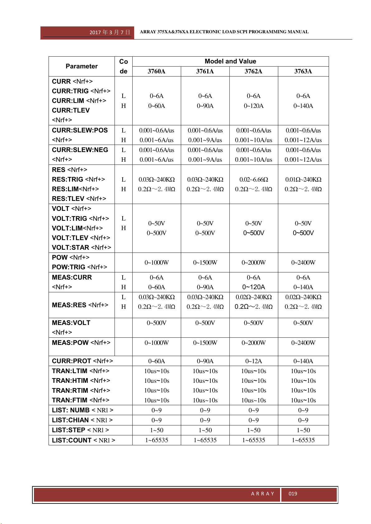
Programming Parameters
The following table lists the programming parameters for 375X&376X series electronic load. Please refer to the
User`s Guide for more details.
2017 年 3 月 7 日
ARRAY 375XA&376XA ELECTRONIC LOAD SCPI PROGRAMMING MANUAL
A R R A Y
017
Parameter
Co
de
Model and Value
3750A
3751A
3752A
3753A
CURR <Nrf+>
CURR:TRIG <Nrf+>
CURR:LIM <Nrf+>
CURR:TLEV
<Nrf+>
L
H
0~6A
0~100A
0~6A
0~150A
0~6A
0~75A
0~6A
0~160A
CURR:SLEW:POS
<Nrf+>
L
H
0.001~0.6A/us
0.001~10A/us
0.001~0.6A/us
0.001~15A/us
0.001~0.6A/us
0.001~7.5A/us
0.001~0.6A/us
0.001~16A/us
CURR:SLEW:NEG
<Nrf+>
L
H
0.001~0.6A/us
0.001~10A/us
0.001~0.6A/us
0.001~15A/us
0.001~0.6A/us
0.001~7.5A/us
0.001~0.6A/us
0.001~16A/us
RES <Nrf+>
RES:TRIG <Nrf+>
RES:LIM<Nrf+>
RES:TLEV <Nrf+>
L
H
0.02Ω~240KΩ
0.2Ω~2.4MΩ
0.01Ω~240KΩ
0.2Ω~2.4MΩ
0.02~6.66Ω
0.2Ω~2.4MΩ
0.01Ω~240KΩ
0.2Ω~2.4MΩ
VOLT <Nrf+>
VOLT:TRIG <Nrf+>
VOLT:LIM<Nrf+>
VOLT:TLEV <Nrf+>
VOLT:STAR <Nrf+>
L
H
0~24V
0~240V
0~24V
0~240V
0~24V
0~240V
0~24V
0~240V
POW <Nrf+>
POW:TRIG <Nrf+>
0~1500W
0~2000W
0~1000W
0~2400W
MEAS:CURR
<Nrf+>
L
H
0~6A
0~100A
0~6A
0~150A
0~6A
0~75A
0~6A
0~160A
MEAS:RES <Nrf+>
L
H
0.02Ω~240KΩ
0.2Ω~2.4MΩ
0.02Ω~240KΩ
0.2Ω~2.4MΩ
0.02Ω~240KΩ
0.2Ω~2.4MΩ
0.02Ω~240KΩ
0.2Ω~2.4MΩ
MEAS:VOLT
<Nrf+>
0~240V
0~240V
0~240V
0~240V
MEAS:POW <Nrf+>
0~1500W
0~2000W
0~1000W
0~2400W
CURR:PROT <Nrf+>
0~100A
0~150A
0~75A
0~160A
TRAN:LTIM <Nrf+>
TRAN:HTIM <Nrf+>
TRAN:RTIM <Nrf+>
TRAN:FTIM <Nrf+>
10us~10s
10us~10s
10us~10s
10us~10s
10us~10s
10us~10s
10us~10s
10us~10s
10us~10s
10us~10s
10us~10s
10us~10s
10us~10s
10us~10s
10us~10s
10us~10s
LIST: NUMB < NRl >
0~9
0~9
0~9
0~9
LIST:CHIAN < NRl >
0~9
0~9
0~9
0~9
LIST:STEP < NRl >
1~50
1~50
1~50
1~50
LIST:COUNT < NRl >
1~65535
1~65535
1~65535
1~65535
2017 年 3 月 7 日
ARRAY 375XA&376XA ELECTRONIC LOAD SCPI PROGRAMMING MANUAL
A R R A Y
018
Parameter
Co
de
Model and Value
3754A
3755A
3756A
CURR <Nrf+>
CURR:TRIG <Nrf+>
CURR:LIM <Nrf+>
CURR:TLEV
<Nrf+>
L
H
0~8A
0~180A
0~8A
0~240A
0~8A
0~260A
CURR:SLEW:POS
<Nrf+>
L
H
0.001~0.8A/us
0.001~18A/us
0.001~0.8A/us
0.001~20A/us
0.001~0.8A/us
0.001~22A/us
CURR:SLEW:NEG
<Nrf+>
L
H
0.1~0.8A/us
0.001~18A/us
0.1~0.8A/us
0.001~20A/us
0.1~0.8/us
0.001~22A/us
RES <Nrf+>
RES:TRIG <Nrf+>
RES:LIM<Nrf+>
RES:TLEV <Nrf+>
L
H
0.01Ω~240KΩ
0.2Ω~2.4MΩ
0.01Ω~240KΩ
0.2Ω~2.4MΩ
0.01~240KΩ
0.2Ω~2.4MΩ
VOLT <Nrf+>
VOLT:TRIG <Nrf+>
VOLT:LIM<Nrf+>
VOLT:TLEV <Nrf+>
VOLT:STAR <Nrf+>
L
H
0~24V
0~240V
0~24V
0~240V
0~24V
0~240V
POW <Nrf+>
POW:TRIG <Nrf+>
0~3000W
0~4000W
0~5000W
MEAS:CURR
<Nrf+>
L
H
0~8A
0~180A
0~8A
0~240A
0~8A
0~260A
MEAS:RES <Nrf+>
L
H
0.01Ω~240KΩ
0.2Ω~2.4MΩ
0.01Ω~240KΩ
0.2Ω~2.4MΩ
0.01Ω~240KΩ
0.2Ω~2.4MΩ
MEAS:VOLT
<Nrf+>
0~240V
0~240V
0~240V
MEAS:POW <Nrf+>
0~3000W
0~4000W
0~5000W
CURR:PROT <Nrf+>
0~180A
0~240A
0~260A
TRAN:LTIM <Nrf+>
TRAN:HTIM <Nrf+>
TRAN:RTIM <Nrf+>
TRAN:FTIM <Nrf+>
10us~10s
10us~10s
10us~10s
10us~10s
10us~10s
10us~10s
10us~10s
10us~10s
10us~10s
10us~10s
10us~10s
10us~10s
LIST: NUMB < NRl >
0~9
0~9
0~9
LIST:CHIAN < NRl >
0~9
0~9
0~9
LIST:STEP < NRl >
1~50
1~50
1~50
LIST:COUNT < NRl >
1~65535
1~65535
1~65535
2017 年 3 月 7 日
ARRAY 375XA&376XA ELECTRONIC LOAD SCPI PROGRAMMING MANUAL
A R R A Y
019
Parameter
Co
de
Model and Value
3760A
3761A
3762A
3763A
CURR <Nrf+>
CURR:TRIG <Nrf+>
CURR:LIM <Nrf+>
CURR:TLEV
<Nrf+>
L
H
0~6A
0~60A
0~6A
0~90A
0~6A
0~120A
0~6A
0~140A
CURR:SLEW:POS
<Nrf+>
L
H
0.001~0.6A/us
0.001~6A/us
0.001~0.6A/us
0.001~9A/us
0.001~0.6A/us
0.001~10A/us
0.001~0.6A/us
0.001~12A/us
CURR:SLEW:NEG
<Nrf+>
L
H
0.001~0.6A/us
0.001~6A/us
0.001~0.6A/us
0.001~9A/us
0.001~0.6A/us
0.001~10A/us
0.001~0.6A/us
0.001~12A/us
RES <Nrf+>
RES:TRIG <Nrf+>
RES:LIM<Nrf+>
RES:TLEV <Nrf+>
L
H
0.03Ω~240KΩ
0.2Ω~2.4MΩ
0.03Ω~240KΩ
0.2Ω~2.4MΩ
0.02~6.66Ω
0.2Ω~2.4MΩ
0.01Ω~240KΩ
0.2Ω~2.4MΩ
VOLT <Nrf+>
VOLT:TRIG <Nrf+>
VOLT:LIM<Nrf+>
VOLT:TLEV <Nrf+>
VOLT:STAR <Nrf+>
L
H
0~50V
0~500V
0~50V
0~500V
0~50V
0~500V
0~50V
0~500V
POW <Nrf+>
POW:TRIG <Nrf+>
0~1000W
0~1500W
0~2000W
0~2400W
MEAS:CURR
<Nrf+>
L
H
0~6A
0~60A
0~6A
0~90A
0~6A
0~120A
0~6A
0~140A
MEAS:RES <Nrf+>
L
H
0.03Ω~240KΩ
0.2Ω~2.4MΩ
0.03Ω~240KΩ
0.2Ω~2.4MΩ
0.02Ω~240KΩ
0.2Ω~2.4MΩ
0.02Ω~240KΩ
0.2Ω~2.4MΩ
MEAS:VOLT
<Nrf+>
0~500V
0~500V
0~500V
0~500V
MEAS:POW <Nrf+>
0~1000W
0~1500W
0~2000W
0~2400W
CURR:PROT <Nrf+>
0~60A
0~90A
0~12A
0~140A
TRAN:LTIM <Nrf+>
TRAN:HTIM <Nrf+>
TRAN:RTIM <Nrf+>
TRAN:FTIM <Nrf+>
10us~10s
10us~10s
10us~10s
10us~10s
10us~10s
10us~10s
10us~10s
10us~10s
10us~10s
10us~10s
10us~10s
10us~10s
10us~10s
10us~10s
10us~10s
10us~10s
LIST: NUMB < NRl >
0~9
0~9
0~9
0~9
LIST:CHIAN < NRl >
0~9
0~9
0~9
0~9
LIST:STEP < NRl >
1~50
1~50
1~50
1~50
LIST:COUNT < NRl >
1~65535
1~65535
1~65535
1~65535

2017 年 3 月 7 日
ARRAY 375XA&376XA ELECTRONIC LOAD SCPI PROGRAMMING MANUAL
A R R A Y
020
Parameter
Co
de
Model and Value
3764A
3765A
3766A
CURR <Nrf+>
CURR:TRIG <Nrf+>
CURR:LIM <Nrf+>
CURR:TLEV
<Nrf+>
L
H
0~8A
0~160A
0~8A
0~180A
0~8A
0~200A
CURR:SLEW:POS
<Nrf+>
L
H
0.001~0.8A/us
0.001~14A/us
0.001~0.8A/us
0.001~15A/us
0.001~0.8A/us
0.001~16A/us
CURR:SLEW:NEG
<Nrf+>
L
H
0.1~0.8A/us
0.001~14A/us
0.1~0.8A/us
0.001~15A/us
0.1~0.8/us
0.001~16A/us
RES <Nrf+>
RES:TRIG <Nrf+>
RES:LIM<Nrf+>
RES:TLEV <Nrf+>
L
H
0.02Ω~240KΩ
0.2Ω~2.4MΩ
0.02Ω~240KΩ
0.2Ω~2.4MΩ
0.02~240KΩ
0.2Ω~2.4MΩ
VOLT <Nrf+>
VOLT:TRIG <Nrf+>
VOLT:LIM<Nrf+>
VOLT:TLEV <Nrf+>
VOLT:STAR <Nrf+>
L
H
0~50V
0~500V
0~50V
0~500V
0~50V
0~500V
POW <Nrf+>
POW:TRIG <Nrf+>
0~3000W
0~4000W
0~5000W
MEAS:CURR
<Nrf+>
L
H
0~8A
0~160A
0~8A
0~180A
0~8A
0~200A
MEAS:RES <Nrf+>
L
H
0.02Ω~240KΩ
0.2Ω~2.4MΩ
0.02Ω~240KΩ
0.2Ω~2.4MΩ
0.02Ω~240KΩ
0.2Ω~2.4MΩ
MEAS:VOLT
<Nrf+>
0~500V
0~500V
0~500V
MEAS:POW <Nrf+>
0~3000W
0~4000W
0~5000W
CURR:PROT <Nrf+>
0~180A
0~240A
0~260A
TRAN:LTIM <Nrf+>
TRAN:HTIM <Nrf+>
TRAN:RTIM <Nrf+>
TRAN:FTIM <Nrf+>
10us~10s
10us~10s
10us~10s
10us~10s
10us~10s
10us~10s
10us~10s
10us~10s
10us~10s
10us~10s
10us~10s
10us~10s
LIST: NUMB < NRl >
0~9
0~9
0~9
LIST:CHIAN < NRl >
0~9
0~9
0~9
LIST:STEP < NRl >
1~50
1~50
1~50
LIST:COUNT < NRl >
1~65535
1~65535
1~65535
2017 年 3 月 7 日
ARRAY 375XA&376XA ELECTRONIC LOAD SCPI PROGRAMMING MANUAL
A R R A Y
021
3.2 IEEE488.2 Common Commands
Common commands are defined by IEEE488.2 standard. They are to perform the basic functions of the instrument,
such as recognition, reset, distinguishing how to read and clear a status and how to execute a command and a query.
Common commands are accepted and executed when they are sent as separate commands and also as an inserted
portion of the instruction sequences for other programs. Performing a common command does not change the
parser’s position in the command tree, which still remains in its previous place when the common command is
processed. However, this does not mean that common command does not affect subsequent instructions.
The electronic loads respond to 14 kinds of required common commands, which control internal operation,
synchronization, status and event register, and system data. As 375X&376X series electronic loads have full trigger
capability, they all respond to *TRG command. What’s more, the electronic loads allow using six selectable
common commands to set and query Status Register. Please refer to Chapter 2.2.14 for details.
*CLS
This command clears the following registers:
Standard Event Register
Questionable Status Register
Operation Status Register
Status Byte Register
Error Queeu
Command Syntax: *CLS
Parameters: None
*ESE
This command sets the condition of the Standard Event Enable Register, which determines which events of the
standard event register are allowed to set the *ESB (Event Summary Bit) of the Status Byte Register. A “1” in the
bit position enables the corresponding event of the standard Event Register. All enabled events of the Standard
Event Register are logically-ORed to set the ESB (Bit 5) of the Status Byte egister.
Refer to Chapter IV Register Status Report for details of the three registers.
Command Syntax: *ESE <NRf>
Parameters: 0~255
Power-on Value: refer to *PSC command
Example: *ESE 100
Related Commands: *PSC, *STB?, *ESE?
*ESE?
This command reads the Standard Event Enable Register.
Query Syntax: *ESE?
Parameters: None
Returned Parameters: <NRl>
Related Commands: *ESEm *PSC, *STB?
2017 年 3 月 7 日
ARRAY 375XA&376XA ELECTRONIC LOAD SCPI PROGRAMMING MANUAL
A R R A Y
022
*ESR?
This c reads Standard Event Register. Reading Standard Event Register clears it. The definition for internal bits
Standard Event Register is the same as that for the internal bits of Standard Event Status Enable Register.
Refer to Chapter IV Register Status Report for details of this registers.
Query Syntax: *ESR?
Parameters: None
Returned Parameters: <NRl>
Related Commands: *CLS, *OPC
*IDN?
This command queries for the identification information of the instrument. The returned value consists of four
strings, separated by commas, including information such as manufacturer, product model, firmware version and so
on.
Query Syntax: *IDN?
Parameters: None
Returned Parameters: <aard>
Example: ARRAY,3751A,0,1.20-0.0-1.08
String Information
Array Manufacturer
3751A Product model (represented y four digits with a letter suffix)
0 Always returns 0 (Reserved Position)
1.20-0.0-1.08 Firmware version, consisting three parts: Part I is the firmware version of the host
processor, Part II is the hardware version of the system and Part III is the firmware version
of GPIB.
*OPC
This command reset the OPC Bit (Bit 0) of the Standard Event Register when all pending operations have been
completed. Pending operations are complete when:
● All commands sent before an *OPC have been executed.
● All trigger actions have been completed and the trigger system has returned to the idle state.
*OPC command does not prevent subsequent commands from performing, but OPC bit will not be set until all
pending operations are executed.
Command Syntax: *OPC
Parameters: None
Related Commands: *TRG,*WAI,*OP
*OPC?
This command places an ASCII “1” in the output queue when all pending operations have been completed. Pending
operations are complete when:
● All commands sent before an *OPC have been accomplished.
● All trigger actions have been completed and the trigger system has returned to the idle state.
Unlike *OPC, *OPC? stops the execution of all the subsequent commands. When all pending operations are
2017 年 3 月 7 日
ARRAY 375XA&376XA ELECTRONIC LOAD SCPI PROGRAMMING MANUAL
A R R A Y
023
completed, an ASCII “1” is put in the output queue .While *OPC is commonly placed at the end of a command line
to facilitate the program to monitor the bus data until it receives the character “1”.
Notes: Do not proceeds *OPC? with the trigger level setting command unless EXT is chosen as the trigger
source.
TRIG:IMM, *TRG and GPIB bus trigger followed *OPC? will be forbidden to process, stopping the system
operations. In this case, the only workable way to restore operation is to send a GPIB DCL (Device Clear)
command to the electronic load.
Query Syntax: *OPC?
Parameters: None
Returned Parameters: <NR1>
Related Commands: *OPC,TRIG:SOUR,*WAI
*PSC
This command controls an automatic clearing of the Service Request Enable Register and the Standard Event
Enable Register when the load is a turned on.
1: Prevents the continents of the Service Request Enable Register and the Standard Event Enable Register from
being saved,causing them to be cleared automatically at turn-on. Thus it prevents a PON event from a SRQ
request at turn-on.
0: Saving the contents of the Service Request Enable Register and the Standard Event Enable Register in
nonvolatile memory and automatically restore them at turn-on. Thus it permits a PON event to generate a SRQ
request when powering on.
Command Syntax: *PSC <bool>
Parameters: 0 | 1
Example: *PSC 0
Related Commands: *PSC?
*PSC?
This command queries if the contents of Service Reqest Enable Register and Standard Event Enable Registers are
stored.
Query Syntax: *PSC?
Parameters: None
Returned Parameters: 0 | 1
0:The power-on clearing flag is false, and the related register won’t be cleared at turn-on.
1:The power-on clearing flag is true, and the related register will be cleared at turn-on.
Related Commands: *PSC
*RCL
This command causes the electronic load recalls a set of parameters saved previously by specifying parameters’
address. *RCL also performs the following operations:
1. Force an ABOR command before the reset of any parameter. (This removes all pending trigger values.)
2. Execute an INP:PROT:CLE to clear the protection state of the electronic load after the complete of all
parameters loading.
3. Turn off calibration mode.
2017 年 3 月 7 日
ARRAY 375XA&376XA ELECTRONIC LOAD SCPI PROGRAMMING MANUAL
A R R A Y
024
The electronic load will automatically execute a *RCL 0 to recall the parameters stored in Location 0 at turn-on.
If no parameters have been prestored in the address recalled by *RCL, the same parameters are recalled.
Command Syntax: *RCL <NR1>
Parameters: 0~9
Example: *RCL 5
Related Commands: *RST,*SAV
*RST
This command causes the electronic load to its factory-default states. Simultaneously *RST can also execute the
following operations:
1. Force an ABOR operation before the reset of any parameter. (This removes all pending trigger values.)
2. When all parameters have been reset, performs an INP:PROT:CLE to clear the protection state of the electronic
load
Command Syntax: *RST
Parameters: None
Related Commands: *RCL,*SAV
*SAV
This command stores the current parameters of the electronic load in nonvolatile memory. Ten sets of parameters
(corresponding memory address: 0~9) can be saved in total. Please refer to Table 2-1 in the User’s Manual for
details. The electronic load will automatically recall parameters in Local 0 and set according to it. If no state has
been saved to Location 0, the factory default state is saved.
Command Syntax: *SAV <NR1>
Parameters: 0~9
Example: *SAV 5
Related Commands: *RCL,*RST
*SRE
This command sets the condition of the Service Request Enable Register. This setting determines which events
from the Status Byte Register (see *STB for its bit configuration) are allowed to set the the Request for Service
(RQS). Please refer to Chapter IV Status Register Report for details of the Service Request Enable Register.
Command Syntax: *SRE <NR1>
Parameters: 0~255
Example: *SRE 20
Related Commands: *ESE,*ESR,*PSC,*SRE?
*SRE?
This command reads the value of the Service Request Enable Register.
Query Syntax: *SRE?
Returned Parameters: <NR1>
Related Commands: *PSC
2017 年 3 月 7 日
ARRAY 375XA&376XA ELECTRONIC LOAD SCPI PROGRAMMING MANUAL
A R R A Y
025
*STB?
This command reads Status Byte register. *STB? is different from a serial query. When *STB? reads the Status Byte
register, the MSS bit is returned in Bit 6 and it is not cleared; However, when a serial query reads the same register,
RQS bit is returned in Bit 6 and is cleared. Status reporting will give you more explanations about the Status Byte
register.
Query Syntax: *STB?
Parameters: None
Returned Parameters: <NR1>
*TRG
This command generates a trigger if “BUS” is chosen as the trigger source (TRIG:SOUR BUS). It is essentially
equivalent to GET (Group Execute Trigger) Command.
Command Syntax: *TRG
Parameters: None
Related Commands: ABOR, INIT,TRIG,TRIG:SOUR
*TST?
This query requests the electronic load to conduct a self-test and report the self-test structure. The self-test does not
change the original mode and the parameter settings of the electronic load.
Query Syntax: *TST?
Returned Parameters: <NR1> 0 Self-test Passed
Non-zero Self-test Failure
*WAI
This command requests the electronic load not to execute any subsequent commands until all the pending
operations have been completed. All pending operations are complete when:
● All commands sent before an *OPC have been executed.
● All trigger actions have been completed and the trigger system has returned to the idle state.
Only a GPIB DCL (Device Clear) command sent to the load can abort a *WAI command.
Parameters: None
Related Commands: *OPC,*OPC?
3.3 Subsystem Commands
Subsystem commands are applied to specific Functions of the electronic load. The subsystem commands are
arranged in a tree structure according to the functions. A subsystem is composed of the related function commands,
which may be one single command or several related commands.
2017 年 3 月 7 日
ARRAY 375XA&376XA ELECTRONIC LOAD SCPI PROGRAMMING MANUAL
A R R A Y
026
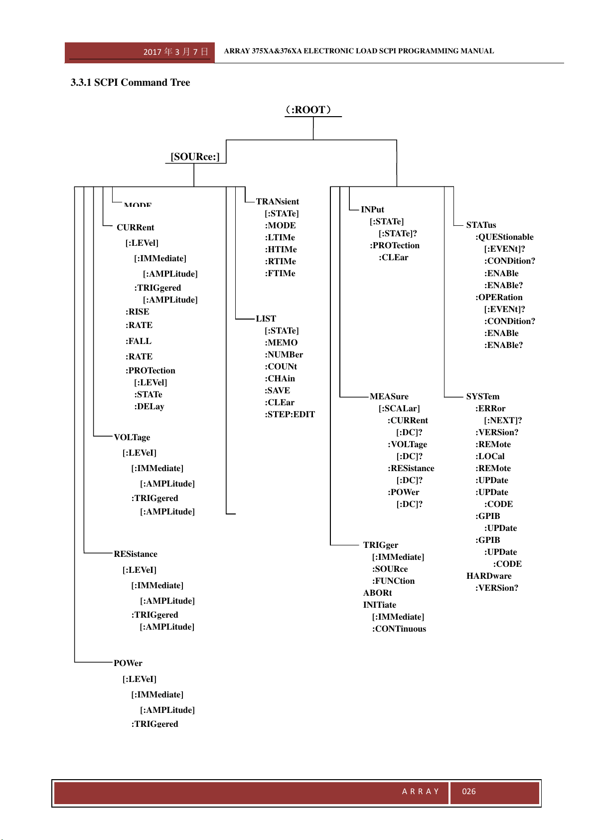
3.3.1 SCPI Command Tree
CURRent
[:LEVel]
[:IMMediate]
[:AMPLitude]
:TRIGgered
[:AMPLitude]
:RISE
:RATE
:FALL
:RATE
:PROTection
[:LEVel]
:STATe
:DELay
[SOURce:]
TRANsient
[:STATe]
:MODE
:LTIMe
:HTIMe
:RTIMe
:FTIMe
RESistance
[:LEVeI]
[:IMMediate]
[:AMPLitude]
:TRIGgered
[:AMPLitude]
INPut
[:STATe]
[:STATe]?
:PROTection
:CLEar
MEASure
[:SCALar]
:CURRent
[:DC]?
:VOLTage
[:DC]?
:RESistance
[:DC]?
:POWer
[:DC]?
STATus
:QUEStionable
[:EVENt]?
:CONDition?
:ENABle
:ENABle?
:OPERation
[:EVENt]?
:CONDition?
:ENABle
:ENABle?
SYSTem
:ERRor
[:NEXT]?
:VERSion?
:REMote
:LOCal
:REMote
:UPDate
:UPDate
:CODE
:GPIB
:UPDate
:GPIB
:UPDate
:CODE
HARDware
:VERSion?
TRIGger
[:IMMediate]
:SOURce
:FUNCtion
ABORt
INITiate
[:IMMediate]
:CONTinuous
VOLTage
[:LEVeI]
[:IMMediate]
[:AMPLitude]
:TRIGgered
[:AMPLitude]
POWer
[:LEVeI]
[:IMMediate]
[:AMPLitude]
:TRIGgered
MODE
LIST
[:STATe]
:MEMO
:NUMBer
:COUNt
:CHAin
:SAVE
:CLEar
:STEP:EDIT
:ROOT
2017 年 3 月 7 日
ARRAY 375XA&376XA ELECTRONIC LOAD SCPI PROGRAMMING MANUAL
A R R A Y
027
ABORt
This command only affects the trigger fuction. It clears all pending trigger settings, all pending trigger operation in
transient or sequence test. It causes the trigger system return to the idel status. It also resets the WTG Bit of the
Operation Condition Register.
Command Syntax: ABORt
Parameters: None
Example: MODE CCH Set the electronic load to enter into CCH mode;
CURR:TRIG 4 Set the trigger current value to 4A;
INIT Perform a trigger initialization;
CURR:TRIG? Query the trigger current level;
4.000E+0 The returned value is 4A;
TRIG Send a trigger signal to conduct a trigger operation;
The immediate current level is 4A;
CURR:TRIG 6 Set the trigger current level to 6A;
INIT Perform a trigger initialization;
ABOR Abort all peding trigger settings and return the trigger system to the idle status;
CURR:TRIG? Query the trigger current level;
4.000E+0 The returned value is still 4A
TRIG Send a trigger signal to conduct a trigger operation;
The trigger current value cannot be trigger and is needed to be reset
Query Syntax: None
Related Commands: CURR:TRIG
,VOLT:TRIG,STAT:OPER:COND?
MODE
[SOURce:]MODE
This command sets the static opertating mode of the electronic load. 375X&376X series electronic load is designed
to be operated in the following modes:
Constant Current Mode: CCL CCH
Constant Voltage Mode: CVL CVH
Constant Power Mode: CP
Constant Resistance Mode: CRL CRH
Notes: If the input is at turn-on, the input will be cut off to avoid current surge when the electronic load
switches its operating mode. If the electronin load is in transient or sequence operation, sending this
command will suspend the present operation, shuts off the input and switch to the corresponding operating
mode.
Command Function
[SOURce:]MODE CCL Set the electronic load to constant current low range mode;
[SOURce:]MODE CCH Set the electronic load to constant current high range mode;
[SOURce:]MODE CVL Set the electronic load to constant voltage low range mode;
[SOURce:]MODE CVH Set the electronic load to constant voltage high range mode;
[SOURce:]MODE CRL Set the electronic load to constant resistance low range mode;
[SOURce:]MODE CRH Set the electronic load to constant resistance high range mode;
[SOURce:]MODE CP Set the electronic load to constant power mode;
Command Syntax: [SOURce:]MODE <AARD>
2017 年 3 月 7 日
ARRAY 375XA&376XA ELECTRONIC LOAD SCPI PROGRAMMING MANUAL
A R R A Y
028
Parameters: CCL|CCH|CVL| CVH|CRL|CRH|CP
Take acronyms of each operating mode as parameters. The default operating mode of the electronic at turn on is
CCH mode.
Example: MODE CCL Set the electronic load to CCL;
Query Syntax: [SOURce:]MODE? Query the present operating mode;
Returned Parameters: <AARD> CCL|CCH|CVL| CVH|CRL|CRH|CP
Related Commands: None
FUNC
[SOURce:]FUNCtion
This command sets the sub-patterns of the electronic load. 375X&376X series electronic load is designed to be
operated in the following sub-patterns:
Static Mode STAT
Transient Mode TRAN
LISTMode LIST
Notes: If the electronic load switches between STAT and TRAN via the command, the operating mode of the
electronic load will not change. For example: If the electronin load is in CCL mode in TRAN, switching to
TRAN mode by this command, the electronic load will be in CCL mode in TRAN.
Command Function
[SOURce:]FUNCtion STAT Set the electronic load to STAT mode;
[SOURce:] FUNCtion TRANsient Set the electronic load to TRAN mode;
[SOURce:] FUNCtion LIST Set the electronic load to LIST mode;
Command Syntax: [SOURce:]FUNC <AARD>
Parameters: STAT|TRAN|LIST
Take abbriviations of each operating mode as parameters. The default operating sub-pattern of the electronic at turn
on is STAT mode.
Example: FUNC TRAN Set the electronic load to transient mode;
Query Syntax: [SOURce:]FUNCtion? Query the current sub-pattern of the electronic load;
Returned Parameters: <AARD> STAT|TRAN|LIST
3.3.2 Current Subsystem
This subsystem controls functions related to current mode.
Command Function
[SOURce:]CURRent[:LEVel][:IMMediate][:AMPLitude] Set the immediate current level in CC mode;
[SOURce:]CURRent[:LEVel][:IMMediate][:AMPLitude]? Query the immediate current level in CC mode;
[SOURce:]CURRent:LIMit Set the current limit level;
[SOURce:]CURRent:LIMit? Query the current limit level;
[SOURce:] CURRent:SLEWrate:NEGative Set the current fall rate;
[SOURce:] CURRent:SLEWrate:NEGative? Query the current fall rate;
[SOURce:] CURRent:SLEWrate:POSitive Set the current rise rate;
[SOURce:] CURRent:SLEWrate: POSitive ? Query the current rise rate;
2017 年 3 月 7 日
ARRAY 375XA&376XA ELECTRONIC LOAD SCPI PROGRAMMING MANUAL
A R R A Y
029
[SOURce:]CURRent:TLEVel Set transient current high level;
[SOURce:]CURRent:TLEVel? Query transient current high level;
[SOURce:]CURRent[:LEVel]:Trigger[:AMPLitude] Set the current trigger level;
[SOURce:]CURRent[:LEVel]:Trigger[:AMPLitude]
? Query the current trigger level;
[SOURce:]CURRent:PROTection [:LEVel] Set current protection limit level;
[SOURce:]CURRent:PROTection [:LEVel]? Query current protection limit level;
[SOURce:]CURRent:PROTection:STATe ON|1 Open overcurrent protection function;
[SOURce:]CURRent:PROTection:STATe OFF|0 Close overcurrent protection function;
[SOURce:]CURRent:PROTection:STATe? Query ON/OFF state of the overcurrent protection function;
[SOURce:]CURRent:PROTection:DELay Set the overcurrent time for trigger the overcurrent protection;
[SOURce:]CURRent:PROTection:DELay? Query the overcurrent time for trigger the overcurrent protection;
Related Subsystem:VOLTage,RESistance
[SOURce:]CURRent[:LEVel][:IMMediate][:AMPLitude]
This command set the immediate current level in CC mode. When the electronic load is turned on, if it is in CC
mode, the command transfers the immediate current level to the input level immediately. If the electronic load is in
other modes, the programmed values will be saved and enabled till the time when the load is in CC mode.
Command Syntax: [SOURce:]CURRent[:LEVel][:IMMediate][:AMPLitude] <NRf+>
Parameters: Figure|MIN|MAX
Unit: A
Example: CURR 25 Set the immediate current level to 25A;
Query Syntax: [SOURce:]CURRent[:LEVel][:IMMediate][:AMPLitude]?
Parameters: None|MIN|MAX
Example: CURR? Query the immediate current level;
CURR? MIN Query the minimum immediate current level;
CURR? MAX Query the maximum immediate current level
Returned Parameters: <NR3> Return the immediate current level;
Related Commands: CURR:LIM
,CURR:SLEW:NEG ,CURR:TRIG
[SOURce:]CURRent:LIMit
This command sets the current limit level of the electronic load. During the current setting operation, if the
programmed current level exceeds the current limit level, the system will take the current limit level as the
programmed current level.
Command Syntax: [SOURce:]CURRent:LIMit <NRf+>
Unit: A
Example: CURR:LIM 100 Set the current limit level to 100A
Query Syntax: [SOURce:]CURRent:LIM?
Parameters: None|MIN|MAX
Example: CURR: LIM? Query the transient current limit level;
Returned Parameters: <NR3>
Related Commands: CURR:PROT
2017 年 3 月 7 日
ARRAY 375XA&376XA ELECTRONIC LOAD SCPI PROGRAMMING MANUAL
A R R A Y
030
[SOURce:] CURRent:SLEWrate:NEGative
This command sets the current fall rate when the current changes from high level to low level in the operation of the
electronic. This command is valid only in CCH and CCL modes.
Command Syntax: [SOURce:] CURRent:SLEWrate:NEGative<NRf+>
Parameters: Figure|MIN|MAX
Unit: A/ us
Example: CURR:SLEW:NEG 5 Set the current fall rate to 5A/us;
Query Syntax: [SOURce:] CURRent:SLEWrate:NEGative?
Parameters: None|MIN|MAX
Example: CURR:SLEW:NEG? Query the transient current fall rate;
CURR:SLEW:NEG?MIN Query the minimum transient current fall rate;
CURR:SLEW:NEG?MAX Query the maximum transient current fall rate;
Returned Parameters: <NR3>
Related Commands: CURR: SLEW:POS
[SOURce:] CURRent:SLEWrate:POSitive
This command sets the current rise rate in CC mode. This command is valid only in CCH and CCL modes.
Command Syntax: [SOURce:] CURRent:SLEWrate:POSitive <NRf+>
Parameters: Figure|MIN|MAX
Unit: A /us
Example: CURR: SLEW: POS 0.2 Set the current rise rate to 0.2A/us
Query Syntax: [SOURce:] CURRent:SLEWrate:POSitive?
Parameters: None|MIN|MAX
Example: CURR:SLEW:POS? Query the transient current rise rate;
CURR:SLEW:POS?MIN Query the minimum transient current rise rate;
CURR:SLEW:POS?MAX Query the maximum transient current rise rate;
Returned Parameters: <NR3>
Related Commands: CURR:SLEW:NEG
[SOURce:]CURRent:TLEVel
Command Syntax: [SOURce:]CURRent[:LEVel]: TLEVel <NRf+>
Parameters: Figure|MIN|MAX
Unit: A
Example: CURR:TLEV 50 Set the transient current high level to 50A;
Query Syntax: [SOURce:]CURRent[:LEVel]:TLEV?
Parameters: None|MIN|MAX
Example: CURR:TLEV? Query the transient current high level;
CURR:TLEV?MIN Query the minimum transient current high level;
CURR:TLEV?MAX Query the maximum transient current high level;
Returned Parameters: <NR3>
Related Commands: CURR
2017 年 3 月 7 日
ARRAY 375XA&376XA ELECTRONIC LOAD SCPI PROGRAMMING MANUAL
A R R A Y
031
[SOURce:]CURRent[:LEVel]:Trigger[:AMPLitude]
This command specifies the trigger current value. After the trigger system is initialized, the electronic load
automatically sets the immediate current value as the trigger current level once a trigger signal received. When the
input of electronic load is turn on, if the load is in CC mode, the command changes the input current immediately. If
the load is in other modes, the programmed values are saved for the time the load is placed in CC mode. The
subsequent trigger signal does not change the input if the trigger current level remains the same.
Command Syntax: [SOURce:]CURRent[:LEVel]:Trigger[:AMPLitude] <NRf+>
Parameters: Figure|MIN|MAX
Unit: A
Example: CURR:TRIG 5A Set the triggerred current to 5A;
CURR:TRIG 0.050 Set the trigger current to 50mA;
Query Syntax: [SOURce:]CURRent[:LEVel]:Trigger[:AMPLitude]?
Parameters: None|MIN|MAX
Example: CURR:TRIG? Query the trigger current value;
CURR:TRIG? MIN Query the minimum trigger current value;
CURR:TRIG? MAX Query the maximum trigger current value;
Returned Parameters: <NR3>
Related Commands: TRIG
[SOURce:]CURRent:PROTection [:LEVel]
This command sets the protection level for the input current. If the input current exceeds the set current limit, the
overcurrent timer starts timing. PT, which indicates the load is in protection, is shown on the front panel, but the
input of the load is not turned off immediately. When the specified delay time is reached, the overcurrent protection
is trigger, then the input of the electronic load is turned off and OC is displayed. In the meantime, OC and PS in the
Questionable Status Register are set. When the overcurrent condition is removed, OC and PS are reset.
Command Syntax: [SOURce:]CURRent:PROTection [:LEVel] <NRf+>
Parameters: Figure|MIN|MAX
Unit: A
Example: CURR:PROT 15 Set the current protection value to 15A;
Query Syntax: [SOURce:]CURRent:PROTection [:LEVel]?
Parameters: None|MIN|MAX
Example: CURR:PROT? Query the current protection value;
CURR:PROT? MIN Query the minimum current protection value;
CURR:PROT? MAX Query the maximum current protection value;
Returned Parameters: <NR3>
Related Commands: CURR:PROT:STAT
,CURR:PROT:DEL
[SOURce:]CURRent:PROTection:STATe
This command enable or disable the current protection function.
Command Syntax: [SOURce:]CURRent:PROTection:STATe <bool>
2017 年 3 月 7 日
ARRAY 375XA&376XA ELECTRONIC LOAD SCPI PROGRAMMING MANUAL
A R R A Y
032
Parameters: ON1|OFF0 1=ON, 0=OFF;
Example: CURR:PROT:STAT ON|1 Enable the current protection function;
CURR:PROT:STAT OFF|0 Disable the current protection function;
Query Syntax: [SOURce:]CURRent:PROTection:STATe?
Parameters: None
Example: CURR:PROT:STAT? Query if the current protection is ON;
Returned Parameters: <bool>
Related Commands: CURR:PROT:DEL
,CURR:PROT
[SOURce:]CURRent:PROTection:DELay
This command sets the delay time of the overcurrent timer. When the input current reaches or exceeds the current
limit, the timer begins to work. When the specified delay time is reached, the overcurrent protection is trigger and
the input of the electronic load is turned off.
Command Syntax: [SOURce:]CURRent:PROTection:DELay <NRf+>
Parameters: Figure|MIN|MAX
Unit: s
Example: CURR:PROT:DEL 0.5 Set the delay time of the overcurrent protection to 0.5s
Query Syntax: [SOURce:]CURRent:PROTection:DELay?
Parameters: None|MIN|MAX
Example: CURR:PROT:DEL? Query the delay time of the overcurrent protection
CURR:PROT:DEL? MIN Query the minimum delay time of the overcurrent protection
CURR:PROT:DEL? MAX Query the maximum delay time of the overcurrent protection
Returned Parameters: <NR3>
Related Commands: CURR:PROT
,CURR:PROT:STAT ON|1
3.3.3 Voltage Subsystem
This subsystem controls the functions related to voltage mode.
Command Function
[SOURce:]VOLTage[:LEVel][:IMMediate][:AMPLitude] Set the immediate voltage value in CV mode;
[SOURce:]VOLTage[:LEVel][:IMMediate][:AMPLitude]? Query the immediate voltage value in CV mode;
[SOURce:]VOLTage:STARt Set the start voltage value;
[SOURce:]VOLTage:STARt ? Query the start voltage value;
[SOURce:]VOLTage:LIMit Set the voltage limit value;
[SOURce:]VOLTage:LIMit? Query the voltage limit value;
[SOURce:]VOLTage:SLEWrate:NEGative Set the voltage fall rate in CV mode;
[SOURce:]VOLTage:SLEWrate:NEGative? Query the voltage fall rate in CV mode;
[SOURce:]VOLTage:SLEWrate:POSitive Set the voltage rise rate in CV mode;
[SOURce:]VOLTage:SLEWrate: POSitive? Query the voltage rise rate in CV mode;
[SOURce:]VOLTage:TLEVel Set the transient voltage high level;
[SOURce:]VOLTage:TLEVel? Query the transient voltage high level;
[SOURce:]VOLTage[:LEVel]:Trigger[:AMPLitude] Set the trigger voltage value;
2017 年 3 月 7 日
ARRAY 375XA&376XA ELECTRONIC LOAD SCPI PROGRAMMING MANUAL
A R R A Y
033
[SOURce:]VOLTage[:LEVel]:Trigger[:AMPLitude]? Query the trigger voltage value;
[SOURce:]VOLTage:PLUS:STAte Set +CV mode ON/OFF;
[SOURce:]VOLTage:PLUS:STAte? Query +CV mode ON/OFF;
[SOURce:]VOLTage:PLUS:LIMit Set the voltage level in +CV mode;
[SOURce:]VOLTage:PLUS:LIMit? Query the voltage level in +CV mode;
Related Subsystem
:CURRent,RESistance
[SOURce:]VOLTage[:LEVel][:IMMediate][:AMPLitude]
This command sets the immediate voltage value in CV mode. When the electronic load is turned on, if it is in CV
mode, the command transfers the immediate voltage level to the input level immediately. If the electronic load is in
other modes, the programmed values will be saved and enabled till the time when the load is in CV mode.
Command Syntax: [SOURce:]VOLTage[:LEVel][:IMMediate][:AMPLitude] <NRf+>
Parameters: Figure|MIN|MAX
Unit: V
Example: VOLT 5 Set the immediate voltage to 5V;
Query Syntax: [SOURce:]VOLTage[:LEVel][:IMMediate][:AMPLitude]?
Parameters: None|MIN|MAX
Example: VOLT? Query the immediate voltage value;
VOLT? MIN Query the minimum immediate voltage level;
VOLT? MAX Query the maximum immediate voltage level;
Returned Parameters: <NR3>
Related Commands: CURRent,RESistance
[SOURce:]VOLTage:STARt
This command sets the start voltage value of the electronic load. When the electronic load is turned on, if the input
voltage is larger than the set start voltage, the electronic load is in working state; if the input voltage is smaller than
the set start voltage, the electronic load is in shut down state. If the start voltage is set to 0, the function is in disable
state.
Command Syntax: [SOURce:]VOLTage:STARt <NRf+>
Parameters: Figure|MIN|MAX
Unit: V
Example: VOLTage:STARt 10 Set the start voltage to 10V;
Query Syntax: VOLTage:STARt?
Parameters: None|MIN|MAX
Example: VOLT:STAR? Query the start voltage level;
Returned Parameters: <NR3>
[SOURce:]VOLTage:LIMit
This command sets the voltage limit level of the electronic load. If the programmed voltage level is larger than the
voltage limit level, the system will take the voltage limit level as the programmed voltage level.
Command Syntax: [SOURce:]VOLTage:LIMit <NRf+>
2017 年 3 月 7 日
ARRAY 375XA&376XA ELECTRONIC LOAD SCPI PROGRAMMING MANUAL
A R R A Y
034
Parameters: Figure|MIN|MAX
Unit: V
Example: VOLT 20 Set the voltage limit level to 20V;
Query Syntax: [SOURce:]VOLTage:LIMit?
Parameters: None|MIN|MAX
Example: VOLT:LIM? Query the voltage limit level
Returned Parameters: <NR3>
[SOURce:] VOLTage:SLEWrate:NEGative
This command sets the voltage fall rate when the voltage changes from high level to low level in the operation of
the electronic. This command is valid only in CVH and CVL modes.
Command Syntax: [SOURce:] VOLTage:SLEWrate:NEGative<NRf+>
Parameters: Figure|MIN|MAX
Unit: V/ us
Example: VOLT:SLEW:NEG 5 Set the voltage fall rate to 5V/us;
Query Syntax: [SOURce:] VOLTage:SLEWrate:NEGative?
Parameters: None|MIN|MAX
Example: VOLT:SLEW:NEG? Query the transient voltage fall rate;
VOLT:SLEW:NEG?MIN Query the minimum transient voltage fall rate;
VOLT:SLEW:NEG?MAX Query the maximum transient voltage fall rate;
Returned Parameters: <NR3>
Related Commands: VOLT: SLEW:POS
[SOURce:] VOLTage:SLEWrate:POSitive
This command sets the voltage rise rate in CV mode. This command is valid only in CVH and CVL modes.
Command Syntax: [SOURce:] VOLTage:SLEWrate:POSitive <NRf+>
Parameters: Figure|MIN|MAX
Unit: V /us
Example: VOLT: SLEW: POS 0.2 Set the voltage rise rate to 0.2V/us;
Query Syntax: [SOURce:] VOLTage:SLEWrate:POSitive?
Parameters: None|MIN|MAX
Example: VOLT:SLEW:POS? Query the voltage rise rate;
VOLT:SLEW:POS?MIN Query the minimum transient voltage rise rate;
VOLT:SLEW:POS?MAX Query the minimum transient voltage rise rate;
Returned Parameters: <NR3>
Related Commands: VOLT:SLEW:NEG
[SOURce:] VOLTage:TLEVel
Command Syntax: [SOURce:] VOLTage [:LEVel]: TLEVel <NRf+>
Parameters: Figure|MIN|MAX
Unit: V
Example: VOLT:TLEV 50 Set the transient voltage high level to 50;
2017 年 3 月 7 日
ARRAY 375XA&376XA ELECTRONIC LOAD SCPI PROGRAMMING MANUAL
A R R A Y
035
Query Syntax: [SOURce:] VOLTage [:LEVel]:TLEV?
Parameters: None|MIN|MAX
Example: VOLT:TLEV? Query the transient voltage high level;
Returned Parameters: <NR3>
Related Commands: CURR
[SOURce:] VOLTage [:LEVel]:Trigger[:AMPLitude]
This command specifies the trigger voltage value. After the trigger system is initialized, the electronic load
automatically sets the immediate voltage value as the trigger voltage level once a trigger signal received. When the
input of electronic load is turn on, if the load is in CV mode, the command changes the input voltage immediately.
If the load is in other modes, the programmed values are saved for the time the load is placed in CVmode. The
subsequent trigger signal does not change the input if the trigger voltage level remains the same.
Command Syntax: [SOURce:] VOLTage [:LEVel]:Trigger[:AMPLitude] <NRf+>
Parameters: Figure|MIN|MAX
Unit: A
Example: VOLT:TRIG 50 Set the trigger voltage to 5V;
VOLT:TRIG 0.050 Set the trigger voltage to 50mV;
Query Syntax: [SOURce:] VOLTage [:LEVel]:Trigger[:AMPLitude]?
Parameters: None|MIN|MAX
Example: VOLT:TRIG? Query the trigger voltage;
VOLT:TRIG? MIN Query the minimum trigger voltage level;
VOLT:TRIG? MAX Query the maximum trigger voltage level;
Returned Parameters: <NR3>
Related Commands: TRIG
[SOURce:]VOLTage:PLUS:STAte
This command open the +CV mode of the electronic load. This command is valid only in CCH, CCL, CRL, CRH
and CP modes.
Command Syntax: VOLTage:PLUS:STAte <bool>
Parameters: ON|OFF
Example: VOLT:PLUS:STA ON Set the input of the +CV mode of the electronic load be ON;
Query Syntax: VOLTage:PLUS:STAte?
Parameters: None
Example: VOLT:PLUS:STA? Query the state of the +CV mode of the electronic load;
Returned Parameters: <NR1> Value:0 for OFF,l for ON
[SOURce:]VOLTage:PLUS:LIMit
This command set the voltage level in +CV mode. When the electronic load is in +CV mode, if the input voltage
level exceeds the set voltage limit level, the electronic load will work in CV mode. And if the input voltage level is
less than the set voltage limit level, the electronic load will work in the corresponding set state.
Command Syntax: [SOURce:]VOLTage:PLUS:LIMit <NRf+>
Parameters: Figure|MIN|MAX
2017 年 3 月 7 日
ARRAY 375XA&376XA ELECTRONIC LOAD SCPI PROGRAMMING MANUAL
A R R A Y
036
Unit: V
Example: VOLT:PLUS:LIM 50 Set the voltage of the +CV mode to 50V
VOLT:PLUS:STA ON Open the +CV mode function function
Query Syntax: [SOURce:]VOLTage:PLUS:LIMit?
Parameters: None|MIN|MAX
Example: VOLT: PLUS:LIM? Query the voltage level in +CV mode;
VOLT: PLUS:LIM? MIN Query the minimum voltage level in +CV mode;
VOLT: PLUS:LIM? MAX Query the maximum voltage level in +CV mode;
Returned Parameters: <NR3>
Related Commands: TRIG
3.3.4 Resistance Subsystem
This subsystem controls the functions related to resistance mode.
Command Function
[SOURce:]RESistance[:LEVel][:IMMediate][:AMPLitude] Set the immediate resistance level in CR mode
(the immediate resistance level is the
transient resistance low level);
[SOURce:]RESistance[:LEVel][:IMMediate][:AMPLitude]? Query the immediate resistance level in CR mode;
[SOURce:]RESistance:LIMit Set the resistance limit low level;
[SOURce:]RESistance:LIMit? Query the resistance limit low level;
[SOURce:]RESistance:SLEWrate:NEGative Set the current fall rate in CR mode;
[SOURce:]RESistance:SLEWrate:NEGative? Query the current fall rate in CR mode;
[SOURce:]RESistance:SLEWrate:POSitive Set the current rise rate in CR mode;
[SOURce:]RESistance:SLEWrate:POSitive? Query the current rise rate in CR mode;
[SOURce:]RESistance:TLEVel Set the transient resistance high level;
[SOURce:]RESistance:TLEVel? Query the transient resistance high leve;
[SOURce:]RESistance[:LEVel]TRIGgered[:AMPLitude] Set the resistance trigger level;
[SOURce:]RESistance[:LEVel]TRIGgered[:AMPLitude]? Query the resistance trigger level;
Related System
:CURRent,VOLTage
[SOURce:]RESistance[:LEVel][:IMMediate][:AMPLitude]
This command sets the immediate resistance level in CR mode. When the electronic load is turned on, if it is in CR
mode, the command transfers the immediate resistance level to the input level immediately. If the electronic load is
in other modes, the programmed values will be saved and enabled till the time when the load is in CR mode.
The units of the set level are different in different modes. The unit is Ω in CRL mode; and it is kΩ in CRH mode.
This command sets the transient resistance low level in transient operation.
Command Syntax:[SOURce:]RESistance[:LEVel][:IMMediate][:AMPLitude] <NRf+>
Parameter
:Figure|MIN|MAX
Unit:Ω | kΩ The unit of the resistance level is Ω in CRL mode;
2017 年 3 月 7 日
ARRAY 375XA&376XA ELECTRONIC LOAD SCPI PROGRAMMING MANUAL
A R R A Y
037
The unit of the resistance level is kΩ in CRH mode;
Example
:RES 10 Set the resistance level to 10Ω in CRL mode;
Set the resistance level to 10kΩ in CRH mode;
Query Syntax:[SOURce:]RESistance[:LEVel][:IMMediate][:AMPLitude]?
Parameter:None|MIN|MAX
Example:RES?; Query the immediate resistance level;
RES? MIN Query the minimum immediate resistance level;
RES? MAX Query the maximum immediate resistance level;
Returned Parameter:<NR3>
Related Command:CURR,VOLT
[SOURce:]RESistance[:LEVel]:TLEVel
This command sets the transient resistance high level in resistance transient operation. In transient operation, the
electronic load switches between the high level and the low level. The high level should be larger than the low level
otherwise the electronic load cannot work normally in transient operation. If the set high level exceeds the range
specification for the present operating mode, an error occurs.
Command Syntax:[SOURce:]RESistance[:LEVel]:HIGH <NRf+>
Parameter:Figure|MIN|MAX
Unit:Ω | kΩ The unit of the resistance is determined by the modes;
It is Ω in TCRL mode; it is KΩ in TCRH mode;
Example:RES:TLEVel 3 Set the transient resistance high level;
Query Syntax:[SOURce:]RESistance[:LEVel]: TLEVel?
Parameter:None|MIN|MAX
Example
:RES: TLEVel? Query the transient resistance high level;
RES: TLEVel? MIN Query the minimum transient resistance high level;
RES: TLEVel? MAX Query the maximum transient resistance high level;
Returned Parameter:<NR3>
Related Command: RESistance
[SOURce:] RESistance:LIMit
This command set the resistance limit low level of the electronic load in CR mode. During the resistance setting
operation, if the programmed resistance level is lower than the resistance limit low level, the system will take the
resistance limit low level as the programmed resistance level.
Command Syntax:[SOURce:] RESistance:LIMit <NRf+>
Unit:A
Example:CURR:LIM 1 Set the resistance limit low level to 1Ω;
Query Syntax:[SOURce:] RESistance:LIM?
Parameter:None
Example:RES: LIM? Query the resistance limit low level;
Returned Parameter:<NR3>
2017 年 3 月 7 日
ARRAY 375XA&376XA ELECTRONIC LOAD SCPI PROGRAMMING MANUAL
A R R A Y
038
[SOURce:] RESistance:SLEWrate:NEGative
This command sets the current fall rate when the current changes from high level to low level in the operation of the
electronic. This command is valid only in CRH and CRL modes.
Command Syntax
:[SOURce:] RESistance:SLEWrate:NEGative<NRf+>
Parameter:Figure|MIN|MAX
Unit:A/ us
Example:RESistance:SLEW:NEG 5 Set the current fall rate of te transient resistance to 5A/ us;
Query Syntax:[SOURce:] RESistance:SLEWrate:NEGative?
Parameter:None|MIN|MAX
Example:RES:SLEW:NEG? Query the current fall rate of the transient resistance;
RES:SLEW:NEG?MIN Query the minimum current fall rate of the transient resistance;
RES:SLEW:NEG?MAX Query the maximum current fall rate of the transient resistance;
Returned Parameter:<NR3>
Related Command:CURR: SLEW:POS
[SOURce:] RESistance:SLEWrate:POSitive
This command sets the current rise rate in CR mode. This command is valid only in CRH and CRL modes.
Command Syntax:[SOURce:] RESistance:SLEWrate:POSitive <NRf+>
Parameter:Figure|MIN|MAX
Unit:A /us
Example:RES: SLEW: POS 0.2 Set the current rise rate of te transient resistance to 0.2A/us;
Query Syntax:[SOURce:] RESistance:SLEWrate:POSitive?
Parameter
:None|MIN|MAX
Example:RES:SLEW:POS? Query the current rise rate of the transient resistance;
RES:SLEW:POS?MIN Query the minimum current rise rate of the transient resistance;
RES:SLEW:POS?MAX Query the maximum current rise rate of the transient resistance;
Returned Parameter:<NR3>
Related Command:RES:SLEW:NEG
[SOURce:]RESistance[:LEVeI]:TRIGgered[:AMPLitude]
This command specifies the trigger resistance value. After the trigger system is initialized, the electronic load
automatically sets the immediate resistance value as the trigger resistance level once a trigger signal received. When
the input of electronic load is turn on, if the load is in CR mode, the command changes the input resistance
immediately. If the load is in other modes, the programmed values are saved for the time the load is placed in CR
mode.
Before the trigger, it need to initialize the system via INITiate[:IMMediate] or INITiate:CONTinuous. Otherwise
it won’t trigger.
Command Syntax:[SOURce:]RESistance[:LEVeI]:TRIGgered[:AMPLitude] <NRf+>
Parameter:Figure|MIN|MAX
Unit:Ω | kΩ
Example
:RES:TRIG 3 Set the trigger resistance level;
2017 年 3 月 7 日
ARRAY 375XA&376XA ELECTRONIC LOAD SCPI PROGRAMMING MANUAL
A R R A Y
039
Query Syntax:[SOURce:]RESistance[:LEVeI]:TRIGgered[:AMPLitude]?
Parameter
:None|MIN|MAX
Example:RES:TRIG? Query the trigger resistance level;
RES:TRIG? MIN Query the minimum trigger resistance level;
RES:TRIG? MAX Query the maximum trigger resistance level;
Returned Parameter:<NR3>
Related Command:INIT,INIT:CONT
3.3.5 Power Subsystem
This subsystem controls functions related to power mode.
Command Function
[SOURce:]POWer[:LEVeI] [:IMMediate][:AMPLitude] Set the immediate power level;
[SOURce:]POWer[:LEVeI] [:IMMediate][:AMPLitude]? Query the immediate power level;
[SOURce:]POWer:LIMit Set the maximum power limit level;
[SOURce:]POWer:LIMit? Query the maximum power limit level;
[SOURce:]POWer:SLEWrate:NEGative Set the current fall rate in CP mode;
[SOURce:]POWer:SLEWrate:NEGative? Query the current fall rate in CP mode;
[SOURce:]POWer:SLEWrate:POSitive Set the current rise rate in CP mode;
[SOURce:]POWer:SLEWrate:POSitive? Query the current rise rate in CP mode;
[SOURce:]POWer:TLEVel Set the power high level in transient power mode;
[SOURce:]POWer:TLEVel? Query the power high level in transient power mode;
[SOURce:]POWer[:LEVeI]:TRIGgered[:AMPLitude] Set the trigger power level;
[SOURce:]POWer[:LEVeI]:TRIGgered[:AMPLitude]? Query the trigger power level;
Related System
:CURRent,VOLTage,RESistance
[SOURce:]POWer[:LEVeI] [:IMMediate][:AMPLitude]
This command set the immediate power level in CP mode.
Command Syntax:[SOURce:]POWer[:LEVeI] [:IMMediate][:AMPLitude] <NRf+>
Parameter:Figure|MIN|MAX
Unit:W
Example:POW 10 Set the immediate power level to 10W;
Query Syntax:[SOURce:]POWer[:LEVeI] [:IMMediate][:AMPLitude]?
Parameter:None|MIN|MAX
Example:POW? Query the immediate power level;
POW? MIN Query the minimum immediate power level;
POW? MAX Query the maximum immediate power level;
Returned Parameter:<NR3>
Related Command:POW:TRIG
[SOURce:] POWer:LIMit
This command sets the power limit level of the electronic load. During the power setting operation, if the
2017 年 3 月 7 日
ARRAY 375XA&376XA ELECTRONIC LOAD SCPI PROGRAMMING MANUAL
A R R A Y
040
programmed power level exceeds the current limit level, the system will take the power limit level as the
programmed power level.
Command Syntax
:[SOURce:] POWer:LIMit <NRf+>
Unit:W
Example:POW:LIM 100 Set the power limit level to 100W;
Query Syntax:[SOURce:] POWer:LIM?
Parameter:None
Example:POW: LIM? Query the power limit level;
Returned Parameter:<NR3>
[SOURce:] POWer:SLEWrate:NEGative
This command sets the current fall rate when the current changes from high level to low level in the transient power
operation of the electronic. This command is valid only in CP mode
Command Syntax:[SOURce:] POWer:SLEWrate:NEGative<NRf+>
Parameter:Figure|MIN|MAX
Unit:A/ us
Example:POW:SLEW:NEG 5 Set the current fall rate in transient power operation to 5A/ us;
Query Syntax:[SOURce:] POWer:SLEWrate:NEGative?
Parameter:None|MIN|MAX
Example:POW:SLEW:NEG? Query the current fall rate in transient power opetation;
POW:SLEW:NEG?MIN Query the minimum current fall rate in transient power opetation;
POW:SLEW:NEG?MAX Query the minimum current fall rate in transient power opetation;
Returned Parameter:<NR3>
Related Command
:POW: SLEW:POS
[SOURce:] POWer:SLEWrate:POSitive
This command sets the current rise rate in CP mode. This command is valid only in CP mode.
Command Syntax:[SOURce:] POWer:SLEWrate:POSitive <NRf+>
Parameter:Figure|MIN|MAX
Unit:A /us
Example:POW: SLEW: POS 0.2 Set the current rise rate in transient power operation to 0.2A/us;
Query Syntax:[SOURce:] POWer:SLEWrate:POSitive?
Parameter:None|MIN|MAX
Example:POW:SLEW:POS? Query the current rise rate in transient power opetation;
POW:SLEW:POS?MIN Query the minimum current rise rate in transient power opetation;
POW:SLEW:POS?MAX Query the minimum current rise rate in transient power opetation;
Returned Parameter:<NR3>
Related Command:POW:SLEW:NEG
[SOURce:] POWer:TLEVel
Command Syntax:[SOURce:] POWer [:LEVel]: TLEVel <NRf+>
Parameter
:Figure|MIN|MAX
2017 年 3 月 7 日
ARRAY 375XA&376XA ELECTRONIC LOAD SCPI PROGRAMMING MANUAL
A R R A Y
041
Unit:W
Example: POW:TLEV 500 Set the transient power high level to 500W;
Query Syntax: [SOURce:] POWer [:LEVel]:TLEV?
Parameters: None|MIN|MAX
Example: POW:TLEV? Query the transient power high level;
POW:TLEV?MIN Query the minimum transient power high level;
POW:TLEV?MAX Query the maximum transient power high level;
Returned Parameters: <NR3>
Related Commands: POW
[SOURce:]POWer[:LEVeI]:Trigger[:AMPLitude]
This command specifies the trigger power value. After the trigger system is initialized, the electronic load
automatically sets the immediate power value as the trigger power level once a trigger signal received. When the
input of electronic load is turn on, if the load is in CP mode, the command changes the input power immediately. If
the load is in other modes, the programmed values are saved for the time the load is placed in CP mode. The
Before the trigger, it need to initialize the system via INITiate[:IMMediate] or INITiate:CONTinuous. Otherwise
it won’t trigger.
Command Syntax: [SOURce:]POWer[:LEVeI]:Trigger[:AMPLitude] <NRf+>
Parameters: Figure|MIN|MAX
Unit: W
Example: POW:TRIG 10W Set the trigger power level to 10W;
Query Syntax: [SOURce:]POWer[:LEVeI]:Trigger[:AMPLitude]?
Parameters: None|MIN|MAX
Example: POW:TRIG? Query the trigger power level;
POW:TRIG? MIN Query the minimum trigger power level;
POW:TRIG? MAX Query the minimum trigger power high level;
Returned Parameters: <NR3>
Related Commands: INIT
,INIT:CONT
3.3.6 List Subsystem
This subsystem controls functions related to the list test. The list test operations guarantee that the electronic load
operates in accordance with the preset test steps and the operating mode, load values and duration time for a single
test step can be specified. Up to 10 test lists can be stored in the 375XA series electronic load. And each test list can
contain 50 test steps at most.
Different lists can be chained so that when the present list has been executed, the load can automatically execute the
next chained list. Lists can be processed cyclically. The cycle time is set by the user. The cycle range is 1 to 255. A
list can be chained to itself to achieve the endless cycle of executing.
2017 年 3 月 7 日
ARRAY 375XA&376XA ELECTRONIC LOAD SCPI PROGRAMMING MANUAL
A R R A Y
042
Command Function
[SOURce:]LIST[:STATe] Enable or disable the present list;
[SOURce:]LIST:NUMBer Specify the number for the list that is to edit or execute;
[SOURce:]LIST:NUMBer? Query the number for the list that is to edit or execute;
[SOURce:]LIST:MEMO Set the memo for the present list;
[SOURce:]LIST:MEMO? Query the memo for the present list;
[SOURce:]LIST:COUNt Set the cycle time for the present list;
[SOURce:]LIST:COUNt? Query the cycle time for the present list;
[SOURce:]LIST:CHAin Specify the chain number for the present list;
[SOURce:]LIST:CHAin? Query the chain number for the present list;
[SOURce:]LIST:STEPs Set the step number;
[SOURce:]LIST: STEPs? Query the maximum step number of the present list;
[SOURce:]LIST:CLEar Delete all the steps of the present list;
[SOURce:]LIST:SAVE Save the settings for the present list;
[SOURce:]LIST:STEP:EDIT Edit the specified steps for the present list;
Related Subsystem:TRAN
[SOURce:]LIST[:STATe]
This command enables or disables the present list.
Command Syntax: [SOURce:]LIST[:STATe] <bool>
Parameters: ON
OFF
Example: LIST ON; Enable the present list;
LIST OFF Disable the present list;
[SOURce:]LIST:NUMBer
This command specifies the number for the list that is to be edited or executed. The parameter range is from 0 to 9.
If the list number exceeds the range, an error occurs.
Command Syntax: [SOURce:]LIST:NUMBer <NR1>
Parameters: 0~9
Example: LIST:NUMB 2 Specify List 2 to be edited or executed;
Query Syntax: [SOURce:]LIST:NUMBer?
Returned Parameters: <NR1>,0~6
Example: LIST:NUMB? Query the number for the list that is edited or excuted;
[SOURce:]LIST:MEMO
This command set the memo for the present list. The memo consists of uppercase and lowercase letters, digits and a
variety of symbols.
Command Syntax: [SOURce:]LIST:MEMO “<aard>”
Parameters: 0x20-0x7f
2017 年 3 月 7 日
ARRAY 375XA&376XA ELECTRONIC LOAD SCPI PROGRAMMING MANUAL
A R R A Y
043
Example: LIST:MEMO “ARRAY” Set the memo for the present list as ARRAY;
Query Syntax: [SOURce:]LIST:MEMO?
Returned Parameters: <AARD>
Example: LIST: MEMO? Query the memo for the present list;
[SOURce:]LIST:STEPs
This command sets the total step number for the present list. The maximum step number is 50.
Command Syntax: [SOURce:]LIST:STEPs <NR1>
Parameters: 1-50
Example: LIST:STEP 30 Set the maximum step number for the present list to 30;
Query Syntax: [SOURce:]LIST: STEPs?
Returned Parameters: <NR1>,1~50
Example: LIST: STEP? Query the maximum step number for the present list;
[SOURce:]LIST:STEP:EDIT
This command edits the specified step of the present list. The command parameters include the the step number, the
operation mode, the setting level, the duration time and the time unit.
Command Syntax: [SOURce:]LIST:STEP:EDIT <NR1>,<aard>,<NRf>,<NRf>,<NRf>
Parameters: Figure0~49,CCL|CCH|CRL |CRH|CVL|CVH|CP, Figure|MIN|MAX, Figure|MIN|MAX,单位 S|MS
Example: LIST:EDIT 2,CVL,10V,10,S Edit Step 2 as: CVL, 10V, 10s
Query Syntax: [SOURce:]LIST[:STEP]:EDIT? <NR1>
Parameters: Figure1~50
Example: LIST:EDIT? 2 Query the parameters of Step 2 of the present list;
Returned Parameters: CCL|CCH|CRL |CRH|CVL|CVH|CP, Figure|MIN|MAX, Figure|MIN|MAX,单位 S|MS
[SOURce:]LIST:COUNt
This command set the cycle time of the present list. The parameter range is from 1 to 255. If the set exceeds the
range, an error accurs. If infinite loop is needed, please chain to the list itself via CHAin function link.
Command Syntax: [SOURce:]LIST:COUNt <NR1>
Parameters: 1~255
Example: LIST:COUN 10 Set the present list to execute 10 times and then
enter to the next chained list or stop;
Query Syntax: [SOURce:]LIST:COUNt? Query the cycle time of the present list;
Returned Parameters: <NR1>
Related Commands: LIST:NUMB
,LIST:EDIT
[SOURce:]LIST:CHAin
This command specifies the chained list for the present list.
Command Syntax: [SOURce:]LIST:CHAin <NR1>
2017 年 3 月 7 日
ARRAY 375XA&376XA ELECTRONIC LOAD SCPI PROGRAMMING MANUAL
A R R A Y
044
Parameters: 0~9
Example: LIST:CHA 2 Set List 2 as the chained list for the present list;
Query Syntax: [SOURce:]LIST:CHAin?
Returned Parameters: <NR1>
Example: LIST:CHA? Query the chained list for the present list;
Related Commands: LIST:NUMB
,LIST:MEMO
[SOURce:]LIST:CLEar
This command deletes all steps of the present list.
Command Syntax: [SOURce:]LIST:CLEar
Parameters: None
Example: LIST:CLE Delete all steps of the present list;
Related Commands: LIST:SAVE
[SOURce:]LIST:SAVE
This command saves the settings for the present list, including its memo, test steps, cycle times and chain.
Command Syntax: [SOURce:]LIST:SAVE
Parameters: None
Example: LIST:SAVE Save the settings of the present list;
Related Commands: LIST:CLE
3.3.7 Transient Subsystem
The transient operation allows the electronic load switch between the high level (LevelH) and the low level
(LevelL). This is to test the dynamic characteristics of the power supply. The transient operation can be executed in
CC, CV, CR and CP modes, and has three modes: Continous, Pulse and Toggle.
●Continous The electronic load periodically switches between LevelH and LevelL.
●Pulse Before a trigger occurs, the load remains at Level L. While a trigger is received, the load switches
to LevelH. And after the input has remained at LevelH for a certain time, the load returned to
LevelL again.
●Toggle When a trigger is received, the load switches from the LevelH to the LevelH. When a trigger is
received again, the load switches from the LevelH to LevelL.
The transient operation need to do the following settings: transient low level (LevelL), transient high level (LevelH),
time for transient low level (TimeL), time for transient high level (TimeH), time for rising edge (TimeR), time for
falling edge (TimeF) and operation mode.
Command Function
[SOURce:]TRANsient:MODE Set the operating mode for transient operation;
[SOURce:]TRANsient:MODE? Query the operating mode;
2017 年 3 月 7 日
ARRAY 375XA&376XA ELECTRONIC LOAD SCPI PROGRAMMING MANUAL
A R R A Y
045
[SOURce:]TRANsient:LTIMe Set the time for the transient low level;
[SOURce:]TRANsient:LTIMe? Query the time for the transient low level;
[SOURce:]TRANsient:HTIMe Set the time for the transient high level;
[SOURce:]TRANsient:HTIMe? Query the time for the transient high level;
[SOURce:]TRANsient:RTIMe Set the time for the rising edge;
[SOURce:]TRANsient:RTIMe? Query the time for the rising edge;
[SOURce:]TRANsient:FTIMe Set the time for the falling edge;
[SOURce:]TRANsient:FTIMe? Query the time for the falling edge;
Related Subsystem
:TRIGger Subsystem
The high/low level time ranges from 0 to 10s. The time for rising/falling edge ranges from 10us to 10s. The
resolution is 10us. In transient operation, parameters such as the VON Point and the protection current level should
be considered in advance. As the improper settings of these parameters may casuse the load input to shut off and
consequently interrupt the transient operation.
[SOURce:]TRANsient:MODE
This command selects the operation mode in the transient operation. There are three operation modes: Continuous,
Pulse and Toggle.
Command Syntax: [SOURce:]TRANsient:MODE <aard>
Parameters: CONTinuous|PULSe|TOGGle
Example: TRAN:MODE PULS Select pulse transient operation;
Query Syntax: [SOURce:]TRANsient:MODE?
Returned Parameters: <aard>CONT, PULS, or TOGG
Related Commands: TRIG
[SOURce:]TRANsient:LTIMe
This command sets the low level time in transient operation. If the continuous transient operation is selected, this
command sets the transient low level time. If the pulse or toggle operation is selected, the sets of the command are
invalid.
Command Syntax: [SOURce:]TRANsient:LTIMe <NRf+>
Parameters: Figure|MIN|MAX
Unit: S
Example: TRAN:LTIM 0.5 Set time for the transiemt low level to 500 ms
Query Syntax: [SOURce:]TRANsient:LTIMe?
Parameters: None|MIN|MAX
Example: TRAN:LTIM? Query time for the transient low level;
TRAN:LTIM? MIN Query minimum time for the transient low level;
TRAN:LTIM? MAX Query maximum time for the transient low level;
Returned Parameters: <NR3>
2017 年 3 月 7 日
ARRAY 375XA&376XA ELECTRONIC LOAD SCPI PROGRAMMING MANUAL
A R R A Y
046
Related Commands: TRAN:HTIM
[SOURce:]TRANsient:HTIMe
This command sets the high level time in transient operation. If the continuous or pulse transient operation is
selected, this command sets the transient low level time. If the toggle operation is selected, the sets of the command
are invalid.
Command Syntax: [SOURce:]TRANsient:HTIMe <NRf+>
Parameters: Figure|MIN|MAX
Unit: S
Example: TRAN:HTIM 0.5 Set time for the transiemt high level to 500 ms;
Query Syntax: [SOURce:]TRANsient:HTIMe?
Parameters: None|MIN|MAX
Example: TRAN:HTIM? Query time for the transiemt high level
TRAN:HTIM? MIN Query minimum time for the transient high level;
TRAN:HTIM? MAX Query maximum time for the transient high level;
Returned Parameters: <NR3>
Related Commands: TRAN:LTIM
[SOURce:]TRANsient:RTIMe
This command sets the time for the rising edge in transient operation, namely, the time for the input to rise from the
transient low level to transient high level.
Command Syntax: [SOURce:]TRANsient:RTIMe <NRf+>
Parameters: Figure|MIN|MAX
Unit: S
Example: TRAN:RTIM 0.0001 Set time for the rising edge in transient operation to 100us;
Query Syntax: [SOURce:]TRANsient:RTIMe?
Parameters: None|MIN|MAX
Example: TRAN:RTIM? Set time for the rising edge in transient operation;
TRAN:RTIM? MIN Set minimum time for the rising edge in transient operation;
TRAN:RTIM? MAX Set maximum time for the rising edge in transient operation;
Returned Parameters: <NR3>
Related Commands: TRAN:FTIM
[SOURce:]TRANsient:FTIMe
This command sets the time for the falling edge in transient operation, namely, the time for the input to fall from the
transient high level to transient low level.
Command Syntax: [SOURce:]TRANsient:FTIMe <NRf+>
Parameters: Figure|MIN|MAX
Unit: S
Example: TRAN:FTIM 0.0002 Set time for the falling edge in transient operation to 200us;
Query Syntax: [SOURce:]TRANsient:FTIMe?
Parameters: None|MIN|MAX
2017 年 3 月 7 日
ARRAY 375XA&376XA ELECTRONIC LOAD SCPI PROGRAMMING MANUAL
A R R A Y
047
Example: TRAN:FTIM? Set time for the falling edge in transient operation;
TRAN:FTIM? MIN Set minimum time for the falling edge in transient operation;
TRAN:FTIM? MAX Set maximum time for the falling edge in transient operation;
Returned Parameters: <NR3>
Related Commands: TRAN:RTIM
3.3.8 Input
Subsystem
This subsystem controls the functions related to the load input.
Command Function
INPut[:STATe] Control the ON/OFF of the load input;
INPut[:STATe]? Query the ON or OFFof the load input;
INPut:PROTection:CLEar Clear the load protection status;
INPut[:STATe]
This command enables or disables the input.
Command Syntax: INPut[:STATe] <bool>
Parameters: ON|OFF
Example: INP ON Enable the load input;
Query Syntax: INPut[:STATe]?
Parameters: None
Example: INP? Query the status of the load input
Returned Parameters: <NR1> Value:0 for OFF,l for ON
INPut:PROTection:CLEar
This command clears the protection status of the electronic load: OC, OV, OP, OT an RV. Once and exceptional
condition occurs, the load input is turned off immediately and enters into the protection status. Except for the
specific operations, the electronic load fails to respond to other instructions. And normal state is restored by clearing
protection status.
Command Syntax: INPut:PROTection:CLEar
Parameters: None
Example: INP:PROT:CLE Clear protection status;
Related Commands: INP
3.3.9 MEASure
This subsystem queries the measured values of the input voltage, current, resistance and power.
Command Function
2017 年 3 月 7 日
ARRAY 375XA&376XA ELECTRONIC LOAD SCPI PROGRAMMING MANUAL
A R R A Y
048
MEASure[:SCALar]:CURRent [:DC]? Query the measured value of the input current;
MEASure[:SCALar]:VOLTage [:DC]? Query the measured value of the input voltage;
MEASure[:SCALar]:RESistance[:DC]? Query the measured value of the input resistance;
MEASure[:SCALar]:POWer[:DC]?
Query the measured value of the input power;
Related Subsystem:CURRent,VOLTage,RESistance,POWer
MEASure[:SCALar]:CURRent [:DC]?
This command queries the measured value of the input current.
Command Syntax: MEASure[:SCALar]:CURRent [:DC]?
Parameters: None
Returned Parameters: <NR3>
Example: MEAS:CURR?
Related Commands: MEAS:VOLT?,MEAS:RES?,MEAS:POW?
MEASure[:SCALar]:VOLTage [:DC]?
This command queries the measured value of the input voltage.
Command Syntax: MEASure[:SCALar]:VOLTage [:DC]?
Parameters: None
Returned Parameters: <NR3>
Example: MEAS:VOLT?
Related Commands: MEAS:CURR?,MEAS:RES?,MEAS:POW?
MEASure[:SCALar]:RESistance[:DC]?
This command queries the measured value of the resistance.
Command Syntax: MEASure[:SCALar]:RESistance[:DC]?
Parameters: None
Returned Parameters: <NR3>
Example: MEAS:RES?
Related Commands: MEAS:CURR?,MEAS: VOLT?,MEAS:POW?
MEASure[:SCALar]:POWer[:DC]?
This command queries the measured value of the input power.
Command Syntax: MEASure[:SCALar]:POWer[:DC]?
Parameters: None
Returned Parameters: <NR3>
Example: MEAS:POW?
Related Commands: MEAS:CURR?,MEAS: VOLT?,MEAS: RES?
2017 年 3 月 7 日
ARRAY 375XA&376XA ELECTRONIC LOAD SCPI PROGRAMMING MANUAL
A R R A Y
049
3.3.10 Trigger Subsystem
This subsystem sets trigger-related functions. The trigger operation is applied in the following cases:
Trigger a trigger level
Trigger a transient pulse
Trigger a transient toggle
Trigger a test list
Command Function
TRIGger[:IMMediate] Generate a trigger signal;
TRIGger:SOURce Set the trigger source;
TRIGger:SOURce? Query the trigger source;
INITiate[:IMMediate] Initialize the trigger system;
INITiate:CONTinuous Initialize the trigger system continuously;
INITiate:CONTinuous? Query initialize the trigger system continuously or not;
TRIGger:DELay Set the trigger delay time;
TRIGger:DELay? Query the trigger delay time;
Related Subsystem:LIST,TRAN
Trigger subsystem operates in the pattern showed as below:
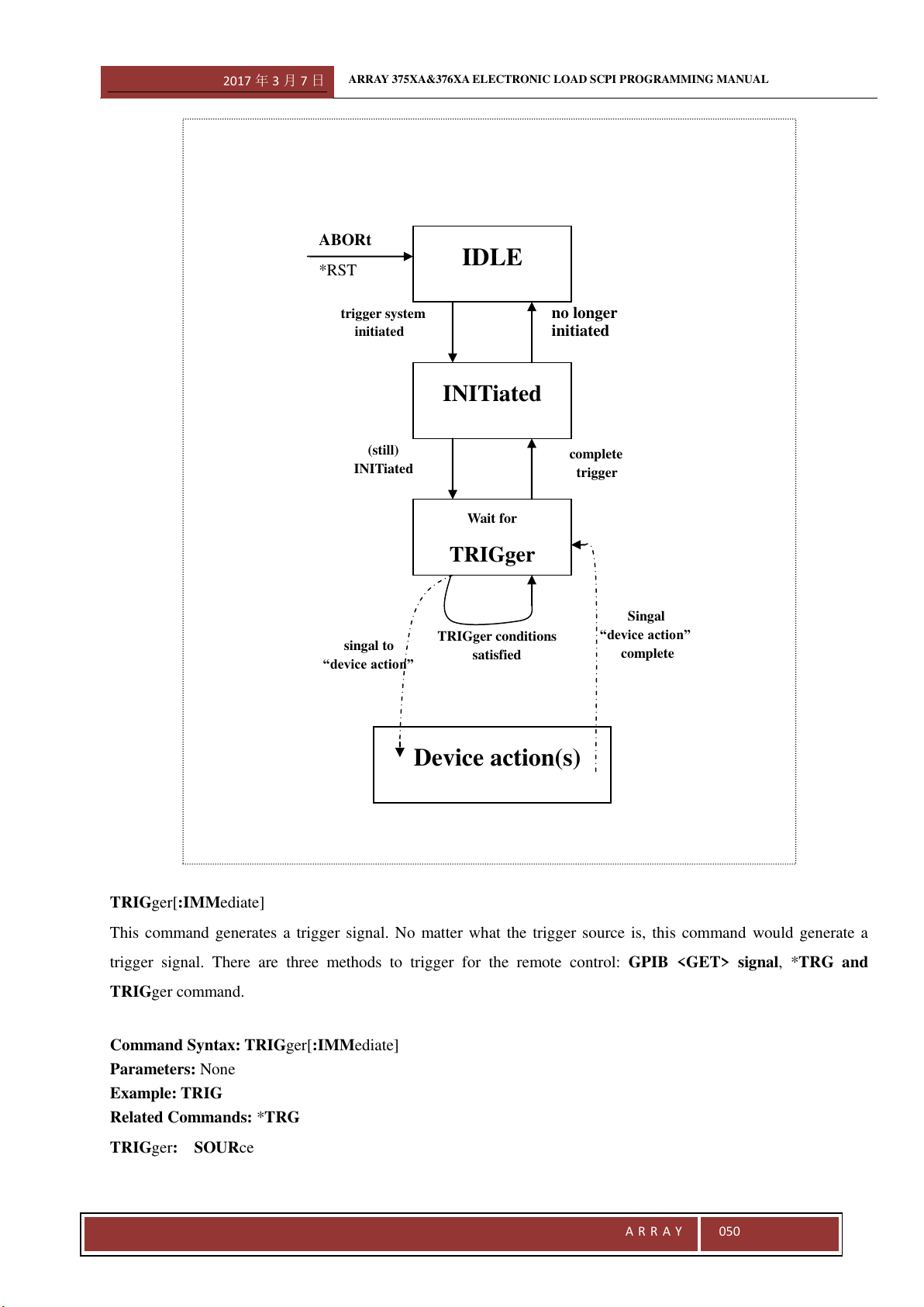
2017 年 3 月 7 日
ARRAY 375XA&376XA ELECTRONIC LOAD SCPI PROGRAMMING MANUAL
A R R A Y
050
TRIGger[:IMMediate]
This command generates a trigger signal. No matter what the trigger source is, this command would generate a
trigger signal. There are three methods to trigger for the remote control: GPIB <GET> signal, *TRG and
TRIGger command.
Command Syntax: TRIGger[:IMMediate]
Parameters: None
Example: TRIG
Related Commands: *TRG
TRIGger: SOURce
IDLE
INITiated
Wait for
TRIGger
Device action(s)
ABORt
*RST
trigger system
initiated
(still)
INITiated
singal to
“device action”
TRIGger conditions
satisfied
Singal
“device action”
complete
complete
trigger
no longer
initiated
2017 年 3 月 7 日
ARRAY 375XA&376XA ELECTRONIC LOAD SCPI PROGRAMMING MANUAL
A R R A Y
051
This command sets the trigger source.
The electronic load has three trigger sources:
BUS GPIB <GET> signal or *TRG functions as the trigger source
EXTernal Select the external trigger input terminal as the trigger source. If the input signal at the
external trigger input terminal is TTL, the falling edge is triggered.
HOLD Only TRIGger[:IMMediate] command can work as the trigger source. All other trigger
methods including *TRG and GPIB <GET> are invald.
Command Syntax: TRIGger:SOURce <aard>
Parameters: BUS| EXTernal| HOLD
Example: TRIG:SOUR EXT Set external trigger as trigger source;
Query Syntax: TRIGger:SOURce?
Returned Parameters: <aard> BUS| EXTernal| HOLD
Example:TRIG:SOUR?
Related Commands: TRIG,*TRG
INITiate[:IMMediate]
This command initializes a trigger operation. The trigger system initialization must be conducted before sending a
trigger signal.
Command Syntax: INITiate[:IMMediate]
Parameters: None
Example: INIT
Related Commands: *TRG
INITiate:CONTinuous
This command enable or disable the continuous initialization function. If the function is enabled, all the subsequent
trigger operations do not need to initialize the trigger system.
Command Syntax: INITiate:CONTinuous 1
Parameters: ON(1)|OFF(0)
Example: INIT:CONT 1
Query Syntax: INITiate:CONTinuous?
Returned Parameters: <NR1> Value:0 for OFF,1 for ON
Example: INIT:CONT?
Related Commands: *TRG
TRIGger:DELay
This command sets the trigger delay time.
Command Syntax: TRIGger:DELay 0.05
Parameters: Figure|MIN|MAX
Unit: S
Example: INIT:CONT 0.01
2017 年 3 月 7 日
ARRAY 375XA&376XA ELECTRONIC LOAD SCPI PROGRAMMING MANUAL
A R R A Y
052
Query Syntax: TRIGger:DELay?
Returned Parameters: <NR3>
Example: TRIGger:DELay?
Related Commands: *TRG
3.3.11 Status
Subsystem
The electronic load uses the following four groups of status registers to record different device status: Status Byte
Register, Standard Event Register, Questionable Status Register and Operation Status Register. Status Byte Register
records the information of other registers.
Command Function
STATus:QUEStionable[:EVENt]? Query Questionable Status Event Register;
STATus:QUEStionable:ENABle Set Questionable Status Enable Register;
STATus:QUEStionable:ENABle? Query Questionable Status Enable Register;
STATus:QUEStionable:CONDition? Query Questionable Status Condition Register;
STATus:OPERation[:EVENt]? Query Operation Status Event Register;
STATus:OPERation:ENABle Set Operation Status Enable Register;
STATus:OPERation:ENABle? Query Operation Status Enable Register;
STATus:OPERation:CONDition? Set Questionable Status Condition Register;
STATus:QUEStionable[:EVENt]?
This command queries Questionable Status Event Register. The electronic load returns a decimal value which
corresponds to the binary-weighted sum of all bits in the register. After the execution of this command, the value of
the Questionable Status Event Register is reset.
Query Syntax
:STATus:QUEStionable[:EVENt]?
Parameters: None
Example: STAT:QUES?
Returned Parameters: <NR1>
STATus:QUEStionable:ENABle
This command sets the Questionable Status Enable Register. Select corresponding bits in Qestionable Status Event
Register by causing the related bits in Questionable Status Enable Register to be set to 1. And QUES bit in Status
Byte Register is set provided any of the selected bits is 1.
Command Syntax: STATus:QUEStionable:ENABle <NRf>
Parameters: 0~65535
Power-on Value:Refer to *PSC Command
Example: STAT:QUES:ENAB 64
STATus:QUEStionable:ENABle?
This command queries Questionable Status Enable Register. The electronic load returns a decimal value which
corresponds to the binary-weighted sum of all bits in the register.
2017 年 3 月 7 日
ARRAY 375XA&376XA ELECTRONIC LOAD SCPI PROGRAMMING MANUAL
A R R A Y
053
Query Syntax:STATus:QUEStionable:ENABle?
Returned Parameters: <NR1>
Example: STAT:QUES:ENAB?
Related Commands: *PSC
STATus:QUEStionable:CONDition?
This command queries Questionable Status Condition Register.
Query Syntax
:STATus:QUEStionable:CONDition?
Parameters: None
Example: STAT:QUES:COND?
Returned Parameters: <NR1>
STATus:OPERation[:EVENt]?
This command queries Operation Status Event Register. The execution of this command resets the value in
Operation Status Event Register to zero.
Query Syntax:STATus:OPERation[:EVENt]?
Parameters: None
Example: STAT:OPER?
Returned Parameters: <NR1>
STATus:OPERation:ENABle
This command sets the Operation Status Enable Register. Select corresponding bits in Opertion Status Event
Register by causing the related bits in Operation Status Enable Register to be set to 1. And QUES bit in Status Byte
Register is set provided any of the selected bits is 1.
Command Syntax: STATus:OPERation:ENABle <NRf>
Parameters: 0~255
Power-on Value
:Refer to *PSCCommand
Example: STAT:OPER:ENAB 128
Query Syntax: STATus:OPERation:ENABle?
Returned Parameters: <NR1>
Example: STAT:OPER:ENAB?
Related Commands: *PSC
STATus:OPERation:CONDition?
This command queries Operation Status Condition Register.
Query Syntax:STATus:OPERation:CONDition?
Parameters: None
Example: STAT:OPER:COND?
Returned Parameters: <NR1>
2017 年 3 月 7 日
ARRAY 375XA&376XA ELECTRONIC LOAD SCPI PROGRAMMING MANUAL
A R R A Y
054
3.3.12 System Subsystem
The subsystem sets the system-related functions.
Command Function
SYSTem:ERRor[:NEXT]? Query error message;
SYSTem:VERSion? Query the version number of the present SCPI;
SYSTem:LOCal Set the electronic load to the local mode;
SYSTem:REMote Set the electronic load to the remote mode;
SYSTem:BEEPer[:IMMediate]? Trigger the Beeper;
SYSTem:RWLock Lock the keybored; LOCAL key is invalid and only
can be unlocked via command.
SYSTem:ERRor[:NEXT]?
This command reads one error from the error queue. The returned value consists of error numbers and error
messages. The load can store up to 20 error messages. If there are more than 20 errors, the load replaces the last
error stored in the queue with “-350, Too many errors”. Error storage memory reads detected errors according to the
principle of “first-in first-out” (FIFO). The first returned error is the first saved. When an error is read, it is removed
from the error queue. When all errors are read, the electronic load returns “+0, No error”.
*CLS (Clear Status Command) clears error queue, while *RST Command does not. All error records are lost when
the electronic load is turned off.
Command Syntax: SYSTem:ERRor[:NEXT]?
Parameters: None
Example: SYST:ERR? Return the errors in error queue;
Returned Parameters: <NR1>,<aard> Return error number and error explanation;
Related Commands: None
SYSTem:VERSion?
This command queries the present SCPI version. The returned value is a character string in the format of YYYY.V.
Y represents the year of the release and V represents the revision number fro that year. For Example: 1995.0
Command Syntax: SYSTem:VERSion?
Parameters: None
Example: SYST:VERS?
Returned Parameters: <aard>,<NR2>
Related Commands: *IDN?
SYSTem:LOCal
This command sets the electronic load to stay in the loal mode.
Command Syntax: SYSTem:LOCal
Parameters: None
Example: SYST:LOC
2017 年 3 月 7 日
ARRAY 375XA&376XA ELECTRONIC LOAD SCPI PROGRAMMING MANUAL
A R R A Y
055
Related Commands: SYST:REM
SYSTem:REMote
This command sets the electronic load to stay in remote control mode when the operation is conducted over RS-232
interface. In remote control mode, except 2
nd
+Local, all other keys on the front panel are disabled.
Command Syntax: SYSTem:REMote
Parameters: None
Example: SYST:REM
Related Commands: SYST:LOC
SYSTem:RWLock
This command sets the electronic load to stay in remote control mode when the operation is conducted over RS-232
interface. In remote control mode, all other keys on the front panel are disabled.
Command Syntax: SYSTem:RWLock
Parameters: None
Example: SYST: RWL
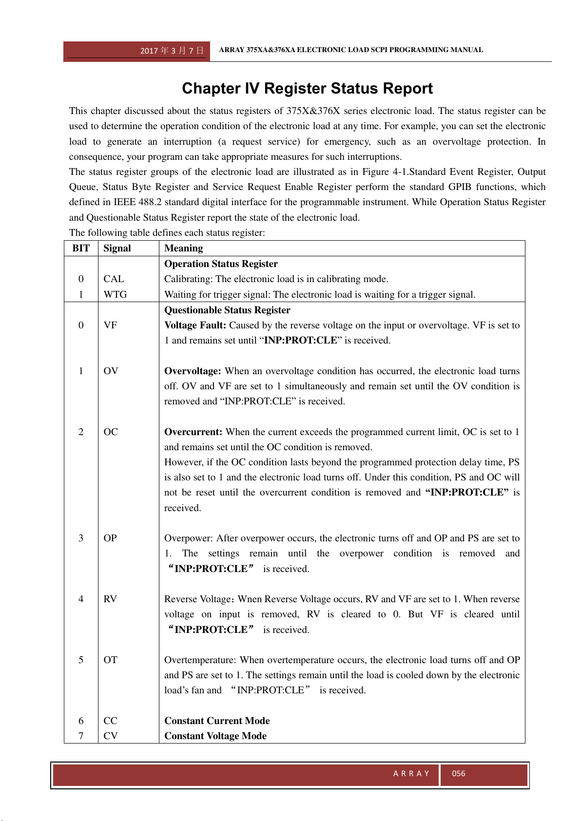
2017 年 3 月 7 日
ARRAY 375XA&376XA ELECTRONIC LOAD SCPI PROGRAMMING MANUAL
A R R A Y
056
Chapter IV Register Status Report
This chapter discussed about the status registers of 375X&376X series electronic load. The status register can be
used to determine the operation condition of the electronic load at any time. For example, you can set the electronic
load to generate an interruption (a request service) for emergency, such as an overvoltage protection. In
consequence, your program can take appropriate measures for such interruptions.
The status register groups of the electronic load are illustrated as in Figure 4-1.Standard Event Register, Output
Queue, Status Byte Register and Service Request Enable Register perform the standard GPIB functions, which
defined in IEEE 488.2 standard digital interface for the programmable instrument. While Operation Status Register
and Questionable Status Register report the state of the electronic load.
The following table defines each status register:
BIT
Signal
Meaning
0
1
CAL
WTG
Operation Status Register
Calibrating: The electronic load is in calibrating mode.
Waiting for trigger signal: The electronic load is waiting for a trigger signal.
0
1
2
3
4
5
6
7
VF
OV
OC
OP
RV
OT
CC
CV
Questionable Status Register
Voltage Fault: Caused by the reverse voltage on the input or overvoltage. VF is set to
1 and remains set until “INP:PROT:CLE” is received.
Overvoltage: When an overvoltage condition has occurred, the electronic load turns
off. OV and VF are set to 1 simultaneously and remain set until the OV condition is
removed and “INP:PROT:CLE” is received.
Overcurrent: When the current exceeds the programmed current limit, OC is set to 1
and remains set until the OC condition is removed.
However, if the OC condition lasts beyond the programmed protection delay time, PS
is also set to 1 and the electronic load turns off. Under this condition, PS and OC will
not be reset until the overcurrent condition is removed and “INP:PROT:CLE” is
received.
Overpower: After overpower occurs, the electronic turns off and OP and PS are set to
1. The settings remain until the overpower condition is removed and
INP:PROT:CLE is received.
Reverse Voltage:Wnen Reverse Voltage occurs, RV and VF are set to 1. When reverse
voltage on input is removed, RV is cleared to 0. But VF is cleared until
INP:PROT:CLE is received.
Overtemperature: When overtemperature occurs, the electronic load turns off and OP
and PS are set to 1. The settings remain until the load is cooled down by the electronic
load’s fan and INP:PROT:CLE is received.
Constant Current Mode
Constant Voltage Mode
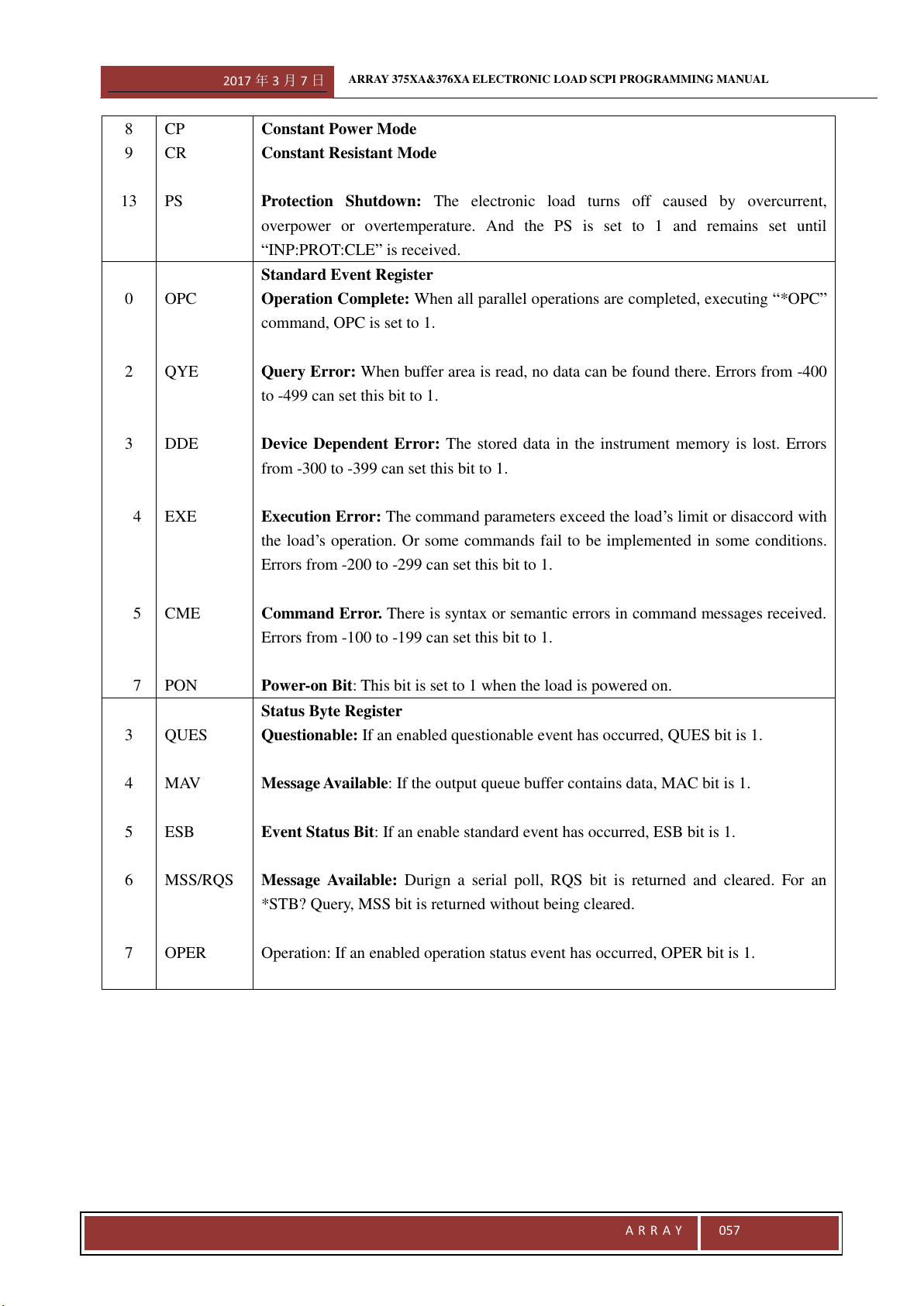
2017 年 3 月 7 日
ARRAY 375XA&376XA ELECTRONIC LOAD SCPI PROGRAMMING MANUAL
A R R A Y
057
8
9
13
CP
CR
PS
Constant Power Mode
Constant Resistant Mode
Protection Shutdown: The electronic load turns off caused by overcurrent,
overpower or overtemperature. And the PS is set to 1 and remains set until
“INP:PROT:CLE” is received.
0
2
3
4
5
7
OPC
QYE
DDE
EXE
CME
PON
Standard Event Register
Operation Complete: When all parallel operations are completed, executing “*OPC”
command, OPC is set to 1.
Query Error: When buffer area is read, no data can be found there. Errors from -400
to -499 can set this bit to 1.
Device Dependent Error: The stored data in the instrument memory is lost. Errors
from -300 to -399 can set this bit to 1.
Execution Error: The command parameters exceed the load’s limit or disaccord with
the load’s operation. Or some commands fail to be implemented in some conditions.
Errors from -200 to -299 can set this bit to 1.
Command Error. There is syntax or semantic errors in command messages received.
Errors from -100 to -199 can set this bit to 1.
Power-on Bit: This bit is set to 1 when the load is powered on.
3
4
5
6
7
QUES
MAV
ESB
MSS/RQS
OPER
Status Byte Register
Questionable: If an enabled questionable event has occurred, QUES bit is 1.
Message Available: If the output queue buffer contains data, MAC bit is 1.
Event Status Bit: If an enable standard event has occurred, ESB bit is 1.
Message Available: Durign a serial poll, RQS bit is returned and cleared. For an
*STB? Query, MSS bit is returned without being cleared.
Operation: If an enabled operation status event has occurred, OPER bit is 1.
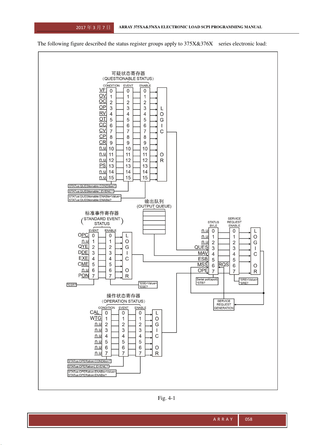
2017 年 3 月 7 日
ARRAY 375XA&376XA ELECTRONIC LOAD SCPI PROGRAMMING MANUAL
A R R A Y
058
The following figure described the status register groups apply to 375X&376X series electronic load:
Fig. 4-1
2017 年 3 月 7 日
ARRAY 375XA&376XA ELECTRONIC LOAD SCPI PROGRAMMING MANUAL
A R R A Y
059
Common Register Model
The Condition Register reflects the present or live state of various load’s signal. Reading the condition register does
not change its bits. Only changes in the load’s state can change the condition register bits. Not all status register
goups have the condition register.
The event register catches the changes in conditions. Each bit in an Event Register corresponds to either a
responsive bit in a Condition Register or a specific condition of the electronic load. If the corresponding condition
in the loads makes one of the following transitions, an event turns to be true.
·Positive Transition (0 to 1)
·Negative Transition (1 to 0)
·Positive or Negative Transition (0 to 1 or 1 to 0)
The Enable Register selects which bits in the Event Register are logically-ORed into a Summary bit. The Enable
Register is reset to zero at turn-on. However, Standard Event Enable Register and Service Request Enable Register
are restored to the state before turn-on if *PSC 0 command is programmed.
Questionable Status Register
The Questionable Status Register reports one or more errors in the device.
A bit in Questionable Status Condition Register indicates the presence of the corresponding errors or unusual
conditions.
The Questionable Status Event Register represents all questionable events that have happened since the last
time this register was read. A condition transition from 0 to 1 on a bit in the Questionable Status Condition
Register will set the correstponding bit in the Questionable Status Event Register. Reading the Questionable
Status Event Register sets it to zero.
The Questionable Status Enable Register determines which questionable status event bits are logically-ORed to
set QUES bit in Status Byte Register.
Output Queue
The output queue is a data structure base on a FIFO (First-in, first out) princle and it stores output messages of the
electronic load until they are read. Once there is a data in this queue, MAV bit in the Status Byte Register is set.
Standard Event Register
Any IEEE488.2 device is typically equipped with a Standard Event register. Any programming errors will set to one
or more bits in the Standard Event Registr.
The Standard Event Register represents all standard events that have happened since the last time this register
was read. Reading this register will set it to zero.
The Standard Event Enable Register sets which standard event bits are logically-ORed to set ESB bit in Status
Byte Register.
2017 年 3 月 7 日
ARRAY 375XA&376XA ELECTRONIC LOAD SCPI PROGRAMMING MANUAL
A R R A Y
060
Operation Status Register
The Operation Status Register records the operation status of the electronic load.
The Operation Status Condition Register reflects the current operation status of the electronic load.
The Operation Status Event Register represents all selected conditions since the last time the register was read.
Regading this register will set it to zero.
The Operation Status Enable Register set which operation event bits are logically-ORed to set OPER bit in the
Status Byte Register.
Status Byte Register
The Status Byte Register collects all status events from other status registers. It can be read by a seriel poll or a
*STB? command.
When this register is read by a *STB? command, Bit 6 of the returned value is the MSS bit. Setting MSS bit
manifests that there is at least one reason for the electronic load to request services. It is the result of Inclusive-OR
after the bits in the Status Byte Register have been screened by Service Request Enable Register.
When a serial poll is sent to respond to a service request, Bit 6 of the returned value is the RQS bit. RQS bit is
latched MSS bit. Once the load needs to request services, it sets SQR signal to true and latch RQS bit
simultaneously. The RQS bit is automatically cleared after a serial poll. And other bits in the Status Byte Register
are not influenced by a serial poll.
*STB? Command does not affect Status Byte Register. *CLS command clears all related Status Registers including
Status Byte Register.
Service Request Enable Register
The Service Request Enable Register specifies setting which bits in the Status Byte Register will generate service
requests. All bits except Bit 6 (RQS/MSS) can be set to generate service requests. Then enabled bits in the Service
Request Enable Register are logically-ORed to become the MSS bit in the Status Byte Register.
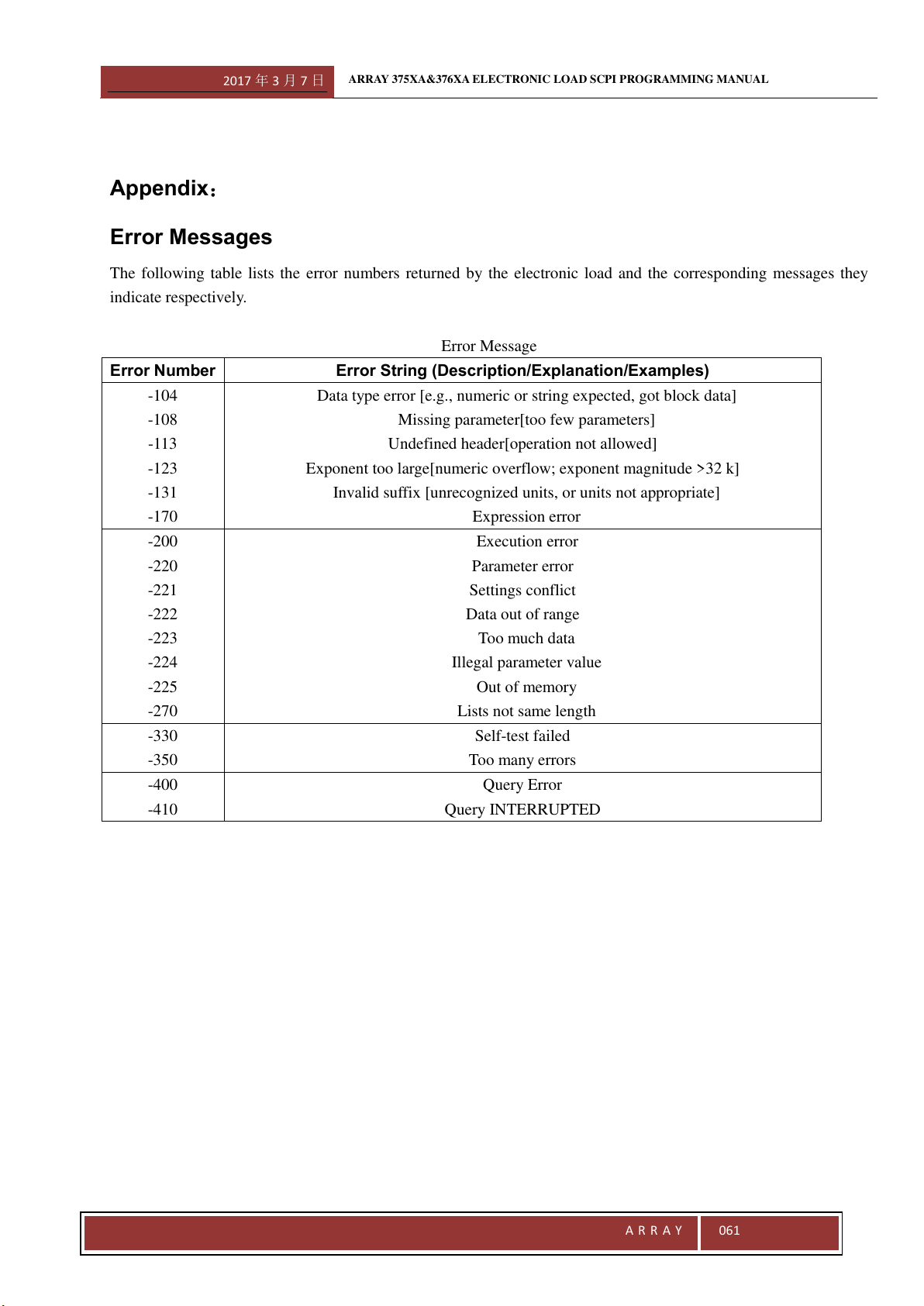
2017 年 3 月 7 日
ARRAY 375XA&376XA ELECTRONIC LOAD SCPI PROGRAMMING MANUAL
A R R A Y
061
Appendix:
Error Messages
The following table lists the error numbers returned by the electronic load and the corresponding messages they
indicate respectively.
Error Message
Error Number
Error String (Description/Explanation/Examples)
-104
-108
-113
-123
-131
-170
Data type error [e.g., numeric or string expected, got block data]
Missing parameter[too few parameters]
Undefined header[operation not allowed]
Exponent too large[numeric overflow; exponent magnitude >32 k]
Invalid suffix [unrecognized units, or units not appropriate]
Expression error
-200
-220
-221
-222
-223
-224
-225
-270
Execution error
Parameter error
Settings conflict
Data out of range
Too much data
Illegal parameter value
Out of memory
Lists not same length
-330
-350
Self-test failed
Too many errors
-400
-410
Query Error
Query INTERRUPTED