Contents
USER’S MANUAL
375X SERIES ELECTRONIC LOAD

Contents
Contents
Safety Instruction …………………………………...…….....................................................1
Chapter I General Introduction ……………………………………………………...……..3
1.1 Function Features …………………………………………………………..……………3
1.2 Front Panel …………………………………………………………………….....……...4
1.3 Rear Panel ……………………………………………………………….……………....5
1.4 Keypad Function ………………………………………………………………..……….5
1.5 Annunciators ……………………………………………………………………..……...7
1.6 Display ………………………………………………………………….……………….8
1.6.1 Main Menu List ………………………………………………………………………8
1.6.2 Port Conguration Menu ………………….…………………………………………9
1.6.3 Transient Operation Menu ……………………………………………….…………10
1.6.4 List Operation Menu ………………………………………………….…………….11
1.6.5 Basic Mode Menu & LCD Information ……………………………………………..13
1.6.5.1 CC Mode Menu ………………………………………………………………….13
1.6.5.2 CR Mode Menu ……………………………………………………………….....14
1.6.5.3 CV Mode Menu ………………………………………………………………….15
1.6.5.4 CP Mode Menu …………………………………………………………………..16
1.6.5.5 +CV Mode Menu ………………………………………..………………………18
1.6.6 Error & Alarm Menu ………………………………………………………………..19
1.6.7 Save Menu ……………………………………………………………………….….19
1.6.7.1 Application Save Menu ………………………………………………………….19
1.6.7.2 Recall Save Menu ………………………………………………………………..20
1.7 Remote Programming ……………………………………………………………….....20
Chapter II Functions and Features ……………………………………………………….21
2.1 Local & Remote Control ……………………………………………………………….21
2.2 Main Functions …………………………………………………………………………21
2.3 Basic Test Functions ……………………………………………………………………22
2.3.1 CC Test …………………………………………………….………………………..22
2.3.1.1 Current Setting Range ……………………………………………….…………..23
2.3.1.2 Immediate Current Level …………………………………………………….….23
2.3.1.3 Triggered Current Level …………………………………………..……………..23
2.3.1.4 Transient Current Vevel …………………………………………..……………...24
2.3.1.5 Software Current Level ……………………………….…………………………24
2.3.2 CV Test …………………………………..………………………………………….24
2.3.2.1 Voltage Setting Range …………………………………………………………...25
2.3.2.2 Immediate Voltage Level ………………………………………..……………….25
2.3.2.3 Triggered Voltage Level …………………………………………..……………..26
2.3.2.4 Transient Voltage Level ……………………………………………….……..…..26
2.3.3 CR Test …………………………………..…………………….……………………26
2.3.3.1 Resistance Setting Range ………………………………………………………...27
2.3.3.2 Immediate Resistance Level …………………………………….…..…………...27
2.3.3.3 Triggered Resistance Level …………………………………….………………..27

Contents
2.3.3.4 Transient Resistance Level …………………………………..……..…………..28
2.3.4 CP Test …………………………………………...………………………………..28
2.3.4.1 Power Setting Range …………………………...………………………………29
2.3.4.2 Immediate Power Level ………………………………………………………...29
2.3.4.3 Triggered Power Level ……………………………………………...………….29
2.3.5 CC+CP Test ………………………………………………………………………..30
2.3.6 CR+CV Test …………………………………………………………………....….30
2.3.7 CP+CV Test ………………………………………………….…………………….31
2.4 Transient Operation ……………………………………………………………...……31
2.4.1 Continuous Transient Operation ……..…………………………………………….32
2.4.2 Pulsed Transient Operation ……………………………………………..…………34
2.4.3 Toggled Transient Operation ……...……………………………………………….36
2.5 List Operation …………………………………………………………………………38
2.6 Triggered Operation …………………………………………………………………..39
2.7 Input Control ………………………………………………………………………….40
2.7.1 ON/OFF of Eload Input ……………………………………………………………40
2.7.2 Von Point/Von Latch ………………………………………………………………40
2.7.3 Current Limit Function in CV Mode ……………………………………………....41
2.7.4 Current Rising Rate ……………………………………………………………......42
2.7.5 Current Falling Rate …………………………………………………………...…..42
2.8 Measurement Function ………………………………………………………….…….43
2.9 Saving and Recalling …………………………………………………………….……43
2.10 Reading Remote Program Errors ………………………………………………..…..45
2.11 Status Report …………………………………………………………….…………..45
2.12 Protection and Alarm Function …………………………………………………..….45
2.12.1 Clearing Latched Protection ……………………………………………………...46
2.12.2 Overvoltage ……………………………………………………………………....46
2.12.3 Overcurrent ……………………………………………………………………….46
2.12.4 Overpower ………………………………………………………………………..47
2.12.5 Overtemperature ………………………………………………………………….47
2.12.6 Reverse Polarity ……………………………………………………………….....48
Chapter III Installation …………………………………………………………………..49
3.1 Initial Check …………………………………………………………………………..49
3.2 Environment/Installation Location …………………………………………………....49
3.3 PowerOn/Self-check …………………………………………………………………..51
3.4 Connection of the Rear Panel ………………………………………………………....52
3.5 Connection of the Front Panel ………………………………………………………...54
3.6 Wiring ………………………………………………………………………...……….55
Chapter IV Local Operation ……………………………………………………………..60
4.1 Local Control …………………………………………………………………...…….60
4.2 Main Operation of the Front Panel …………………………………………………....60
4.3 Connecting to the Power Supply ……………………………………………………...61

Contents
4.4 ON/OFF of Eload Input ……………………………….……………………......……...61
4.5 Basic Operation ……………………….………………………………………….....…61
4.5.1 CC Mode ……………………………………………………………………………62
4.5.2 CV Mode ……………………………………………………………………………64
4.5.3 CR Mode ……………………………………………………………………………66
4.5.4 CP Mode ……………………………………………………………………………68
4.6 +CV Mode ……………..………………………………………………………………70
4.6.1 CC+CV Mode ………………..……………………………………………………..70
4.6.2 CR+CV Mode …………………..…………………………………………………..71
4.6.3 CP+CV Mode ………………..……………………………………………………..72
4.7 Transient Operation ……………………………………………………………………73
4.7.1 Continuous Transient Operation ……………………………………………………73
4.7.2 Pulsed Transient Operation …………………………………………………………75
4.7.3 Toggled Transient Operation ………………………………………………………..77
4.8 List Operation ………………………………………………………………………….79
4.8.1 List Editing …………………………………………………………………….…...80
4.8.2 Starting/Stopping the List …………………………………………………………..83
4.9 Saving and Recalling …………………………………………………………………..84
4.10 Checking and Clearing Protection Setting ……………………………………………86
4.11 Trigger Operation …………………………………………………………………….87
4.12 Main Menu ………………………………………………………………….………..87
4.12.1 Buzzer ……………………………………………………………...……………..88
4.12.2 Encoder ……………………………………………………………………………88
4.12.3 Trigger ……………………………………………………………...……………..89
4.12.4 Calibration …………………………………………………….…………………..89
4.12.5 Information ………………………………………………………………………..89
4.12.6 Safety Code ……………………………………………………………………….90
4.12.7 Date ……………………………………………………………………………….91
4.12.8 Time ……………………………………………………………………………….92
4.12.9 Language ………………………………………………………………………….92
4.12.10 System Default …………………………………………………………………..93
Chapter V Remote Programming Operation …………………………………………….94
5.1 Communication Interface …………………………………………………..………….94
5.1.1 RS232 ………………………………………………...…………………………….94
5.1.2 USB …………………………………………………...……………………………94
5.1.3 GPIB ………………………………………………………………………………..95
5.2 Remote Programming Display …………………………………………………………98
5.3 Sending Remote Setting Commandsb …………………………………………………98
5.4 Returning Data ………………………………………………………………...……….98
5.5 Remote Programming Commands ……………………………………………………..98
5.5.1 Basic Test Mode ……………………………………………………………………99
5.5.2 Transient Level……..……………………………………………………………….99

Contents
5.5.3 Programmable Current Protection …………………………...…………….………..99
5.6 CC Mode Example …………………………………………………………….………..99
5.7 CV Mode Example ………………………………………………………..…………...100
5.8 CR Mode Example ……………………………………………………………..……...100
5.9 Continuous Transient Operation Example ……………………………………….……100
5.10 Pulsed Transient Operation Example …………………………………………….…..101
Specications ………………………………………………………………………………102
Frame Diagram ………………………………………………………………...………….110
Declarations … …………………………………………………………….....……………113

Chapter I General Introduction
ARRAY
1
Safety Instruction
This chapter contains the important safety instructions that the users must follow during operation
and storage. Please read the contents carefully before operation to ensure the safe and optimal use.
Safety Guides:
1. Do not place heavy objects on the instrument. Notes: Only two units can be placed
vertically.
2. To avoid serious impact or improper placement and damage to the instrument.
3. To avoid the electrostatic discharge to the instrument.
4. Please use the matched cable. Please do not use the naked cable.
5. Please do not block or obstruct the ventilation of the fan.
6. Please do not disassemble the instrument unless you are qualified as service personnel.
7. The instrument is not for the measurements performed for CAT I, II and IV.
● (Measure Categories) EN6100-1:2010 specifies the measurement categories and their
requirements as follows. The 375XA falls under category II.
● Measurement category IV is measurement performed at the source of low-voltage installation.
● Measurement category III is for measurement performed in the building installation.
● Measurement category II is for measurement performed on the circuit directly connected to
the low voltage installation.
● Measurement category I is for measurement performed on circuits not directly connected to
the main.
8. Power Supply
● AC Input Voltage: 100~120VAC/200~240VAC (90~132VAC/180~250VAC)
● Frequency: 47~63Hz
● Power: 3751A 80VA Max
● Connect the protective grounding conductor of the AC power cord to an earth ground, to
avoid electrical shock.
9. Cleaning
Disconnect the power before cleaning. Use a soft cloth dampened in a solution of mild
detergent and water. Do not spray any liquid. Do not use chemicals or cleaners containing harsh

Chapter I General Introduction
ARRAY
2
material such as benzene, toluene, xylene and acetone.
10. Operation Environment
● Location: Indoor, no direct sunlight, dust free, almost non-conductive pollution
● Temperature: 0℃~40℃
● Humidity: 0~90% RH
● (Pollution Degrees) EN6100-1:2010 specifies the pollution degree and their requirements as
follows.
● The 375XA falls under degree II.
● Pollution refers to “addition of foreign matter, solid, liquid or gaseous (ionized gases), that
may produce a reduction of dielectric strength or surface resistivity”.
● Pollution degree I: No pollution or only dry, non-conductive pollution accurs. The pollution
has no influence.
● Pollution degree II: Normally only non-conductive pollution occurs. Occasionally, however, a
temporary conductivity caused by condensation must be expected.
● Pollution degree III: Conductive pollution occurs, or dry, non-conductive pollution occurs
which becomes conductive due to condensation which is expected. In such conditions, equipment
is normally protected against exposure to direct sunlight, precipitation, and full wind pressure, but
neither temperature nor humidity is controlled.
11. Storage Environment
● Location: Indoor
● Temperature: -20℃~70℃
● Humidity: <90% RH
12. Disposal
Do not dispose this instrument as unsorted municipal waiste. Please use a separate collection
facility or contact the supplier from which this instrument was purchased. Please make sure
discarded electrical waste is properly recycled to reduce environment impact.

Chapter I General Introduction
ARRAY
3
Chapter I General Introduction
General Introduction of 375XA Eload
ARRAY 375XA electronic load is a new-generation high-performance programmable electronic
load researched by ARRAY ELECTRONIC CO., LTD, which provides powerful test function and
friendly human-machine interface. The electronic load is equipped with RS232, USB and GPIB
interface and supports SCPI standard commands for programmable instrumentation and LabView
development platform, which is widely used in the scientific research and production field of
aerospace, shipbuilding, auto electronics, solar cell and fuel cell.
The “electronic load”, “Eload” or “load” in the manual indicates ARRAY 375XA electronic
load without following instructions.
1.1 Function Features
The main functions and features of ARRAY 375XA Eload are as below:
Four basic testing modes: CC, CV, CR and CP; twelve basic working modes: CCL, CCH,
CVL, CVH, CRL, CRH, CP, CCL+CV, CCH+CV,CRL+CV, CRH+CV, CP+CV;
The 16 bit D/A converters and 24 bit A/D converters incorporated, provide the equipment
with greatly enhanced setting and measurement resolution. The D/A conversion rate can
reach 500 KHz and the high-speed performance is overall increased;
Minimum operating voltage is less than 1.8V at the load’s full rated current. The
maximum current can be achieved even though the input voltage is 0V, which is
especially suitable for the fuel cell, solar cell, auto charger and other new energy test
application. The load is with powerful protection function and is reliable in the most
complicated test environment;
High resolution TFT-LCD display;
High-speed transient test function: the maximum test frequency can reach 50 kHz and the
current response speed can be 15A/us.
Powerful sequential test function: the minimum step time is 10us and the maximum step
time is 99999s. Cyclic times can be set freely and can be chained to another sequence to
realize more complex test procedure;
Chapter I General Introduction
ARRAY
4
The high-efficiency intelligent cooling system can ensure the equipment has a long-term,
full-power, trouble-free and continuous work;
Automatic ON/OFF function effectively simply the test operation;
The combined use of knob and number keypad makes the operation more convenient;
Save/Recall function can save multiple groups of common settings;
With OCP, OPP, OTP protection function and OV, RV alarm function;
Supporting SCPI and LabView and providing necessary PC software.
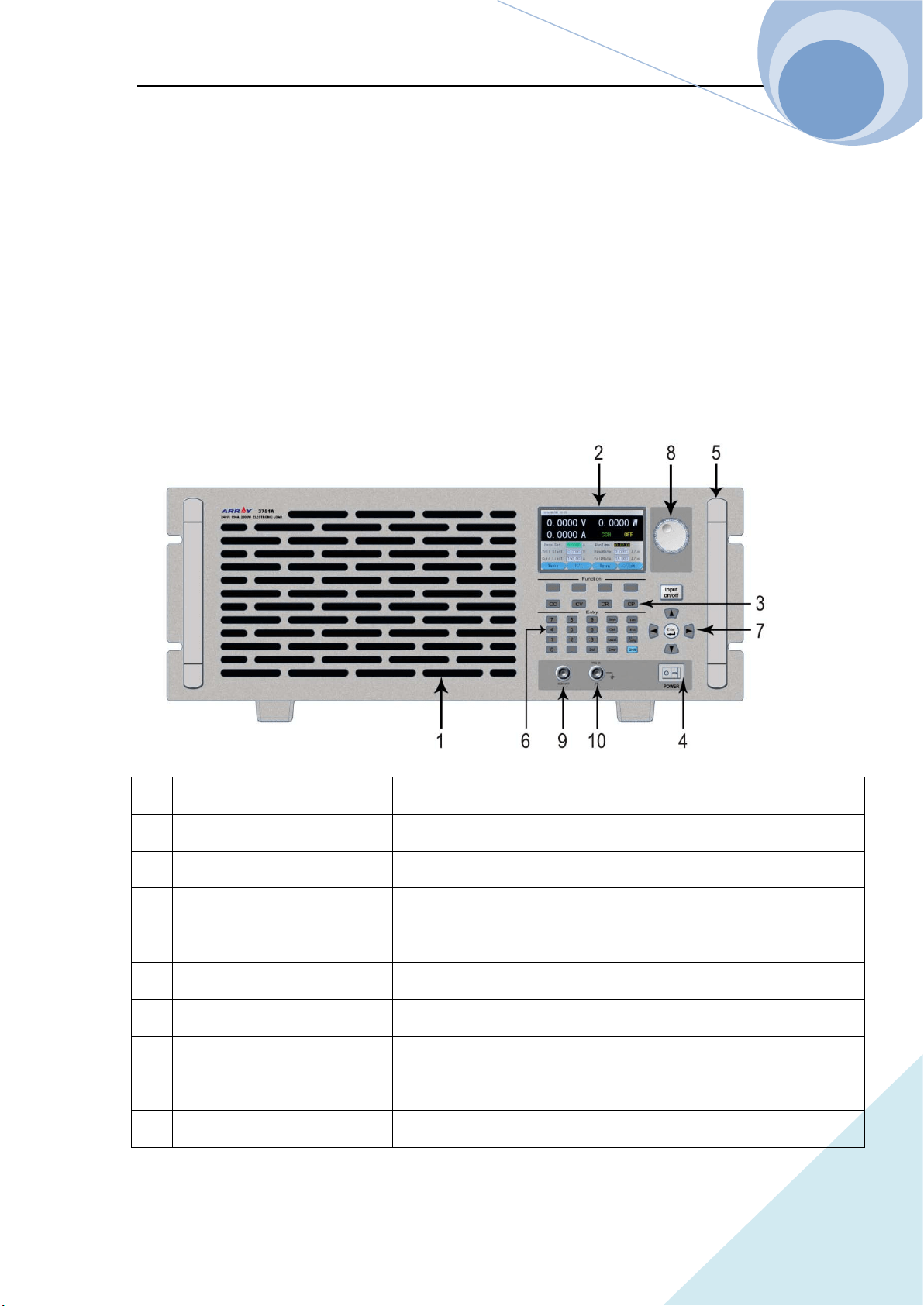
1.2 Front Panel
1 Air Inlet Air inlet of the cooling air dust
2 LCD display To display the state, test value and setting parameter of the instrument
3 Operation mode key To switch the operation mode of the instrument
4 Power Power ON/OFF
5 Handle To handle the instrument
6 Number pad & function keys To enter the numbers and the functions
7 Direction keys & enter key To move the cursor and to confirm
8 Knob To increase /decrease values
9 Current monitor terminal To isolate the output after the test of the present current
10 External trigger input terminal To input the external trigger signal
Chapter I General Introduction
ARRAY
5
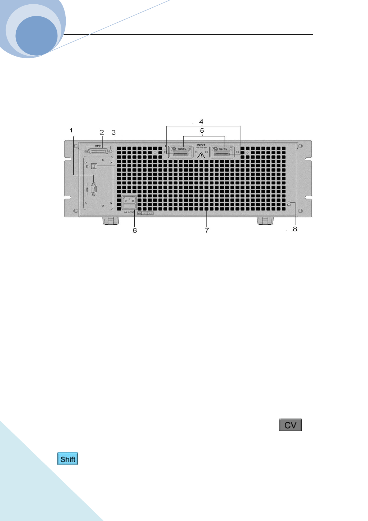
1.3 Rear Panel
The connecting terminals on the rear panel of 375XA series Eload include: the input terminals
(INPUT+ and INPUT-) and voltage test terminals (SENSE+SENSE-), as shown in follows
1. RS232 interface
2. GPIB interface (optional)
3. USB interface
4. Input terminal
5. Voltage test terminal
6. Power input socket & fuse
7. Air outlet
8. Ground terminal: to connect the earth during rack system installation
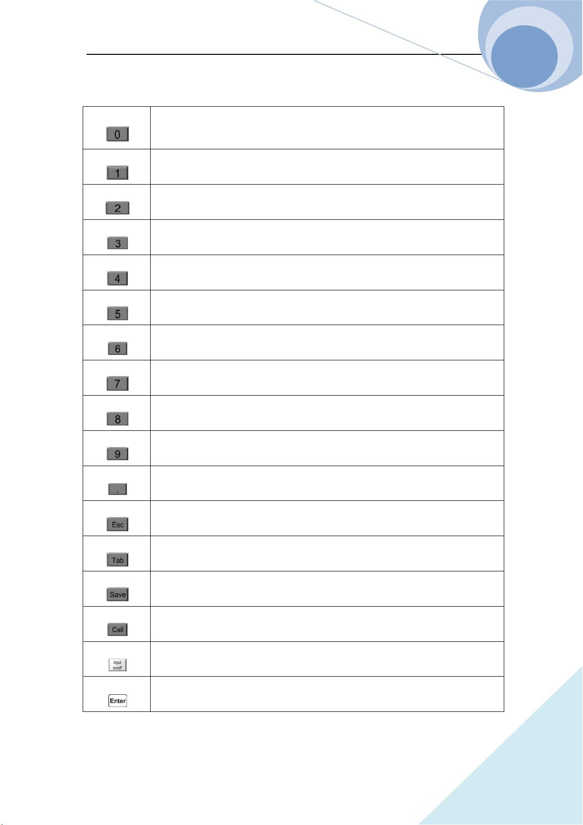
1.4 Keypad Function
There are four types of keys: function keys, number keys, alternative function keys and direction
keys on the keypad. On the alternative function compound key, the black fond is the first function
and the blue fond is the alternative function. For example, CV is the first function of
key and +CV is the alternative function. If the alternative function is needed to be used, press
key first and then press the corresponding compound key.
Chapter I General Introduction
ARRAY
6
Table 1-1 Key Explanation:
Number 0
Number 1
Number 2
Number 3
Number 4
Number 5
Number 6
Number 7
Number 8
Number 9
Dot
Clear
Epitope shift key
Save key
Recall key
Input ON/OFF key
Confirmation key
Chapter I General Introduction
ARRAY
7
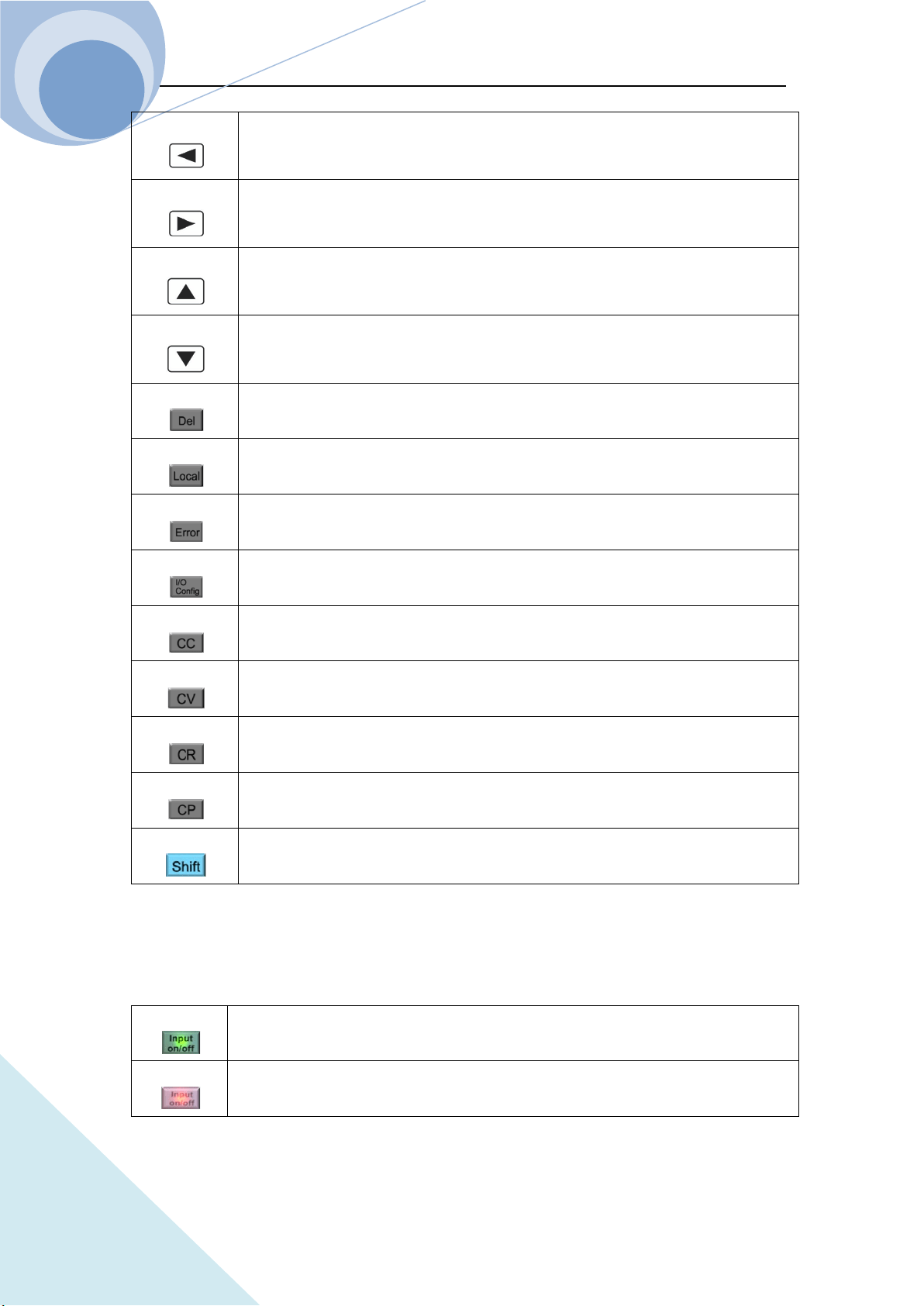
1.5 Annunciators
Table 1-3, Annunciator Explanations:
Green light be on when the input being on
Yellow light be on when the input being standby
Left key
Right key
Upper key
Down key
Delete key
Local key
Error code display key
I/O port configuration key
CC mode selection key
CV mode selection key
CR mode selection key
CP mode selection key
Alternative function shift key
Chapter I General Introduction
ARRAY
8
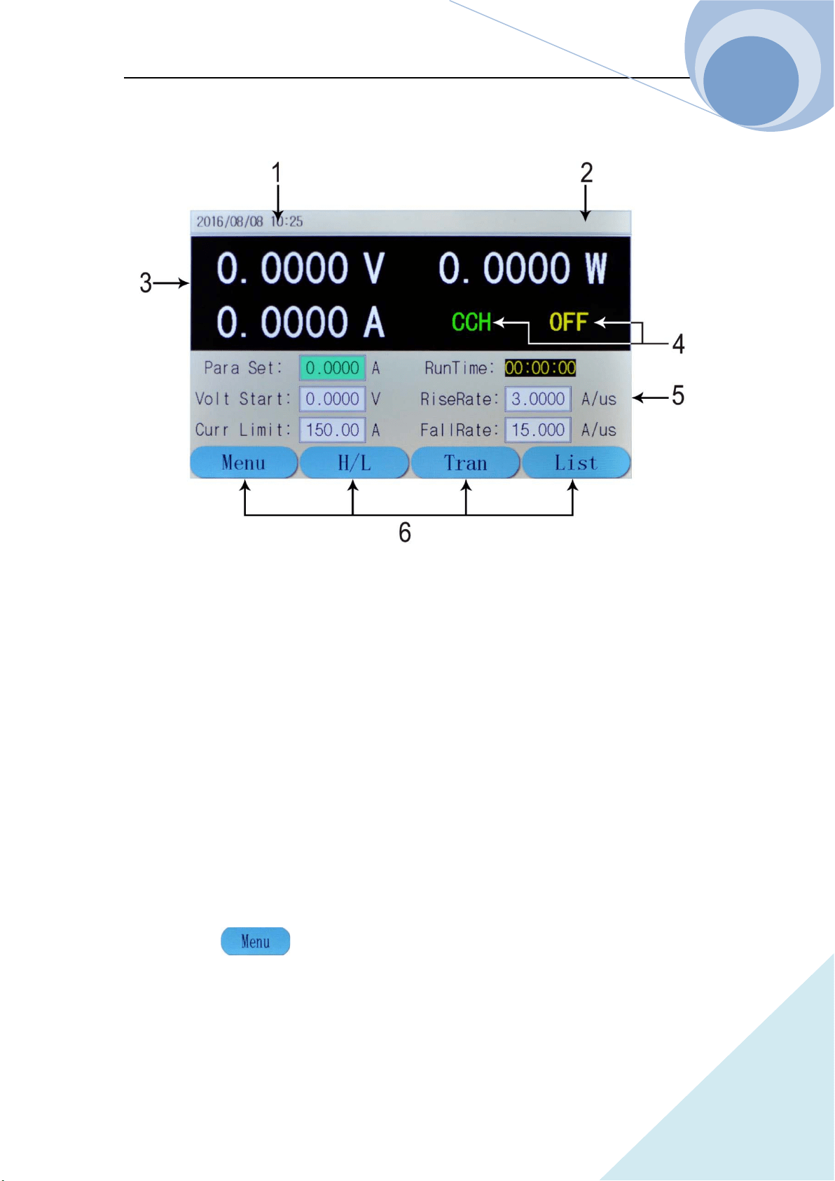
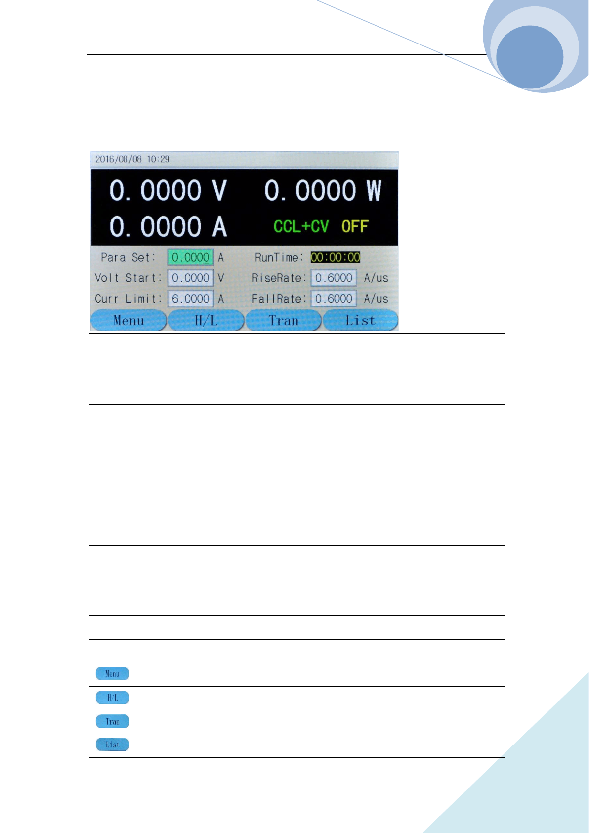
1.6 Display
1. Date and Time To display the current date and time
2. System State To display the current system state
3. Test Value To display the current voltage, current and power value
4. Operation State To display the current operation mode and the input state
5. Current setting Value To display the current setting value
6. Soft Key To indicate the function of the key below the screen
Description of the Main Menu
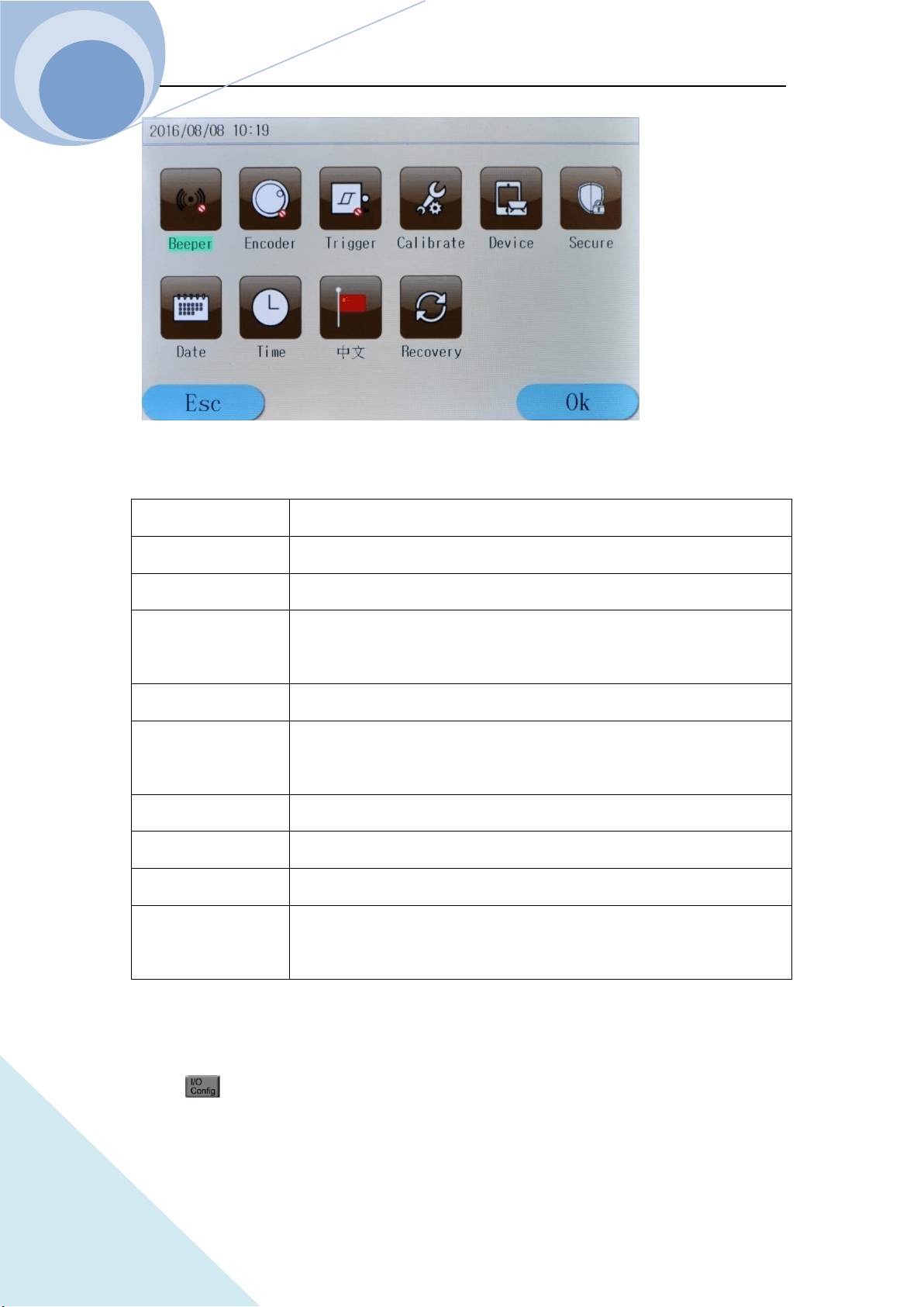
1.6.1 Main Menu List
Press dynamic key to enter the main menu as shown in the following diagram:
Chapter I General Introduction
ARRAY
9
The contents of the main menu are as the follows:
Beeper To control the buzzer work or not;
Encoder To control the encoder work or not;
Trigger To control the trigger work or not;
Calibration To calibrate the accuracy of the Eload
, for details please see
Calibration Methods;
Information To display the factory setting;
Security Code
To set the security code for the instrument to avoid the error operation of
the Calibration menu;
Date To adjust the current date of the system;
Time To adjust the current time of the system;
Language To swift the current language of the system;
Default Factory
Value
The current system can be returned to the default factory value.
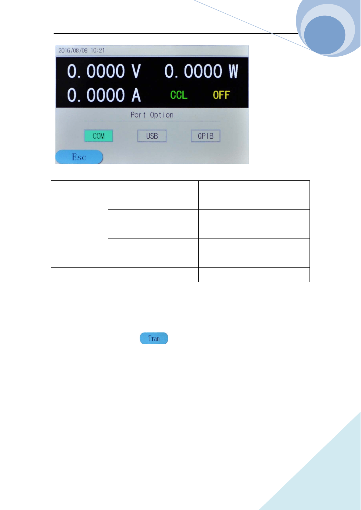
1.6.2 Port Configuration Menu
Press key to enter the I/O configuration menu as follows:
Chapter I General Introduction
ARRAY
10
Port Configuration Com Port USB GPIB
RS232 Interface
Baud Rate 2400 9600 19200 38400 57600 115200
Parity Bit Non Parity/ Even Parity/ Odd Parity
Data Bit 8 Bit 9 Bit
Stop Bit 1 Bit 2 Bit
USB Interface USB
GPIB Interface GPIB Address Address Value
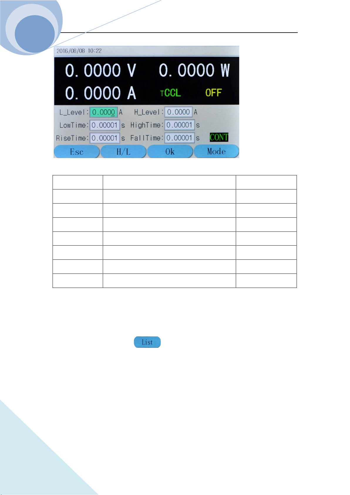
1.6.3 Transient Operation Menu
In basic mode, press dynamic key to enter the corresponding transient operation
menu. The transient operation menu is as follows:
Chapter I General Introduction
ARRAY
11
Function Explanation Parameter Example
L Level Transient Low Level 1.000A
H Level Transient High Level 6.000A
LowTime Time for transient low level 0.6s
HighTime Time for transient high level 0.6s
RiseTime Time for transient rising edge 0.01s
FallTime Time for transient falling edge 0.01s
Mode
Continuous(Cont) Pulse(Puls) Toggle(Togg)
Cont
Notes: Transient operation may be used in CC, CV, CR and CP modes.
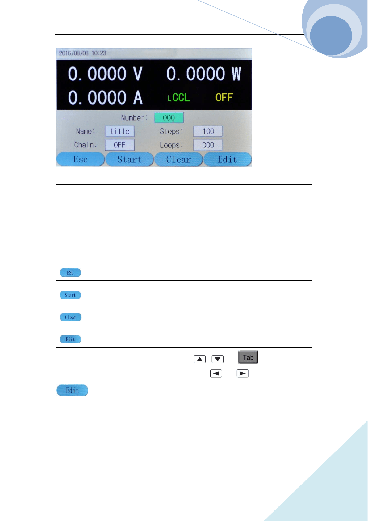
1.6.4 List Operation Menu
In basic mode, press dynamic key to enter the corresponding list operation menu.
The list operation menu is as follows:
Chapter I General Introduction
ARRAY
12
Number
List Steps(0-19)
Name
List Name(5 characters)
Total Steps Total steps of list operation
Execution Times
Loop Times(1-999)
Link
Link(0-19,off)
key
Press this dynamic key to return to the main menu;
key
Press this key to switch between CCL and CCH;
key
Press this key to enter the transient operation;
key
Press this key to enter list data edit mode.
In the list operation menu, Select the function by , or key, and select the
data edition or data modification function by knob, or . Then press dynamic
key to enter the list data edition menu as follows:
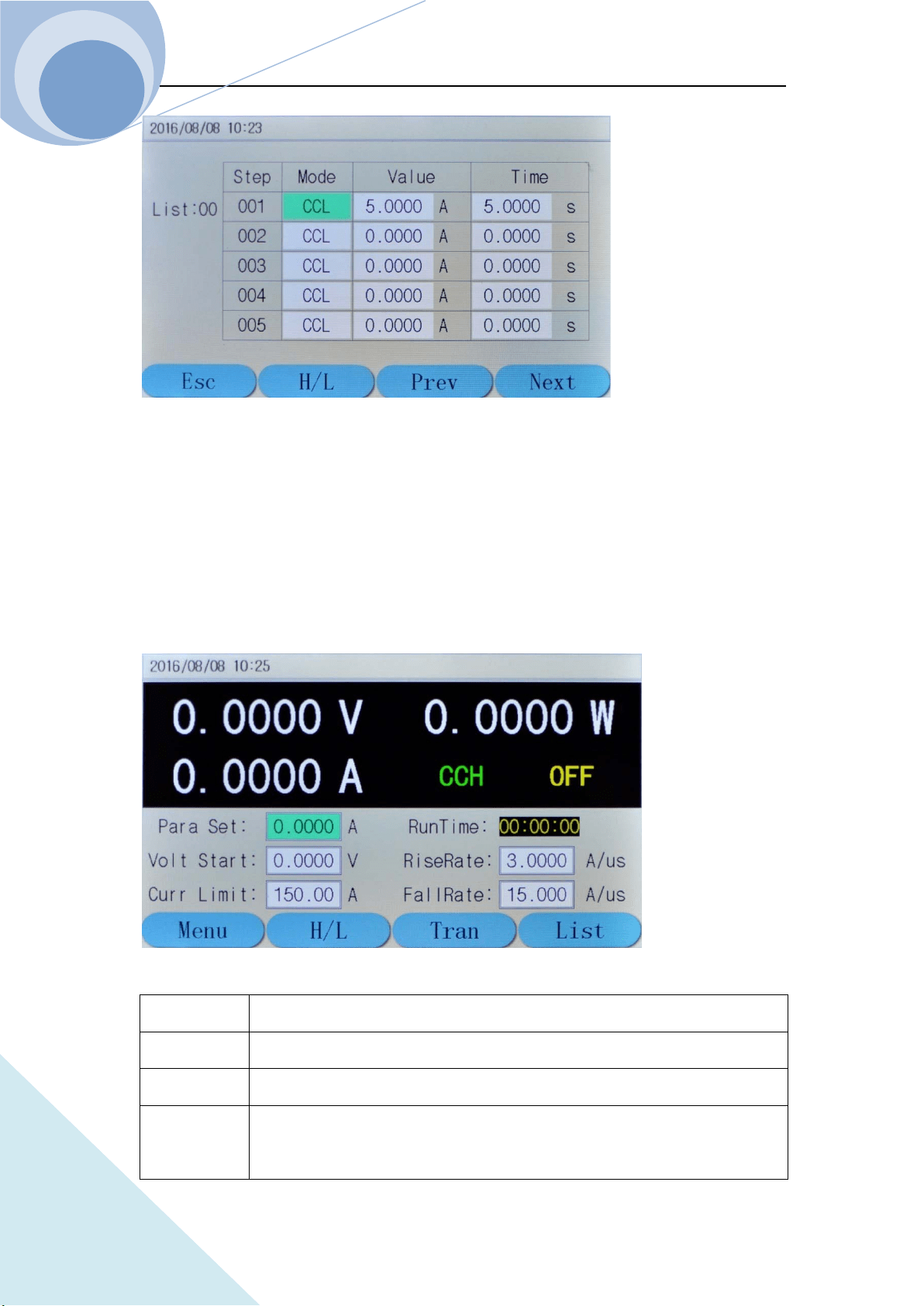
Chapter I General Introduction
ARRAY
13
1.6.5 Basic Mode Menu & LCD Information
1.6.5.1 CC Mode Menu
Description: In Constant Current Mode, the load units will sink the amount of current
programmed. Regardless of the voltage, the current will stay the same. For more details on CC
Mode, please refer to Page 52.
Voltage Value
To display the current input terminal voltage;
Power Value
To display the current power value;
Current Value
To display the current value
Mode CCH indicates constant current high range;
CCL indicates constant current low range;
Chapter I General Introduction
ARRAY
14
Input State ON/OFF;
Run Time To display the time the load being ON, reset when shutdown or switch mode;
Para Set To set the constant current value, unit: A;
Volt Start To set the start voltage of the load, 0 indicates the function being not enabled;
Current Limit To limit the maximum Current level at the mode
Rising Rate To control the current rising rate when starting
Falling Rate To control the current falling rate when starting
key
Press this dynamic key to return to the main menu;
key
Press this key to switch between CCL and CCH;
key
Press this key to enter the transient operation;
key
Press this key to enter list data edit mode.
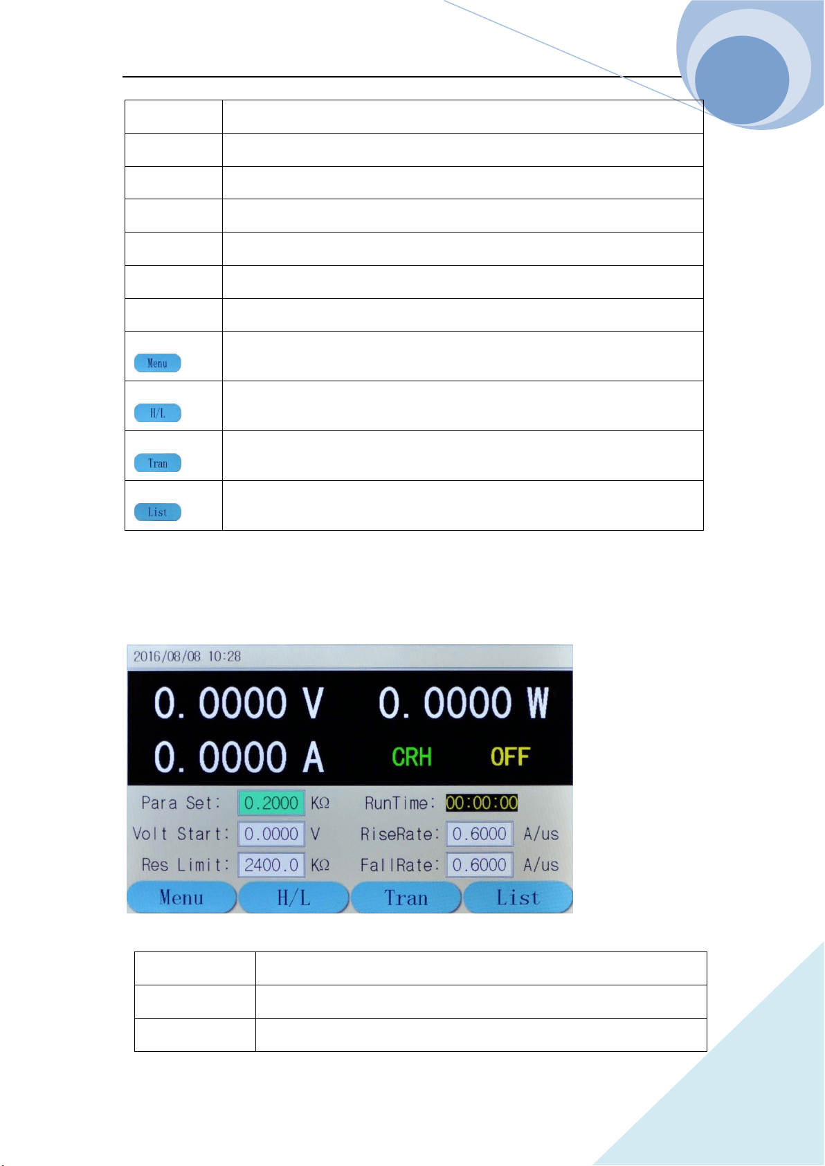
1.6.5.2 CR Mode Menu
Description: In Constant Resistance Mode, the load units will maintain a constant resistive load by
varying the current. For more details on CR Mode, please refer to Page 57.
Voltage Value
To display the current input terminal voltage;
Power Value
To display the current power value;
Current Value
To display the current value
Chapter I General Introduction
ARRAY
15
Mode CRH indicates constant resistance high range;
CRL indicates constant resistance low range;
Input State ON/OFF;
Run Time To display the time the load being ON, reset when shutdown or switch
mode;
Para Set To set the constant resistance value, unit:KΩ;
Volt Start
To set the start voltage of the load, 0 indicates the function being not
enabled;
Res Limit To limit the minimum resistance level at the mode
RiseRate To control the current rising rate when starting
FallRate To control the current falling rate when starting
key
Press this dynamic key to return to the main menu;
key
Press this key to switch between CRL and CRH;
key
Press this key to enter the transient operation;
key
Press this key to enter list operation.
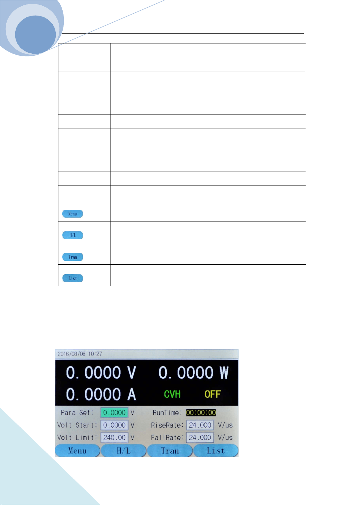
1.6.5.3 CV Mode Menu
Description:In Constant Voltage Mode, the load units will maintain a constant voltage value by
varying the current. For more details on CV Mode, please refer to Page 54.
Chapter I General Introduction
ARRAY
16
Voltage Value
To display the current input terminal voltage;
Power Value
To display the current power value;
Current Value
To display the current value
Mode
CVH indicates constant voltage high range;
CVL indicates constant voltage low range;
Input State
ON/OFF;
Run Time
To display the time the load being ON, reset when shutdown or
switch mode;
Para Set
To set the constant voltage value, unit: V;
Volt Start
To set the start voltage of the load,
0 indicates the function being not enabled;
Volt Limit
To limit the maximum voltage level at the mode
RiseRate
To control the voltage rising rate when starting
FallRate
To control the voltage falling rate when stopping
key
Press this dynamic key to return to the main menu;
key
Press this key to switch between CRL and CRH;
key
Press this key to enter the transient operation;
key
Press this key to enter list operation.
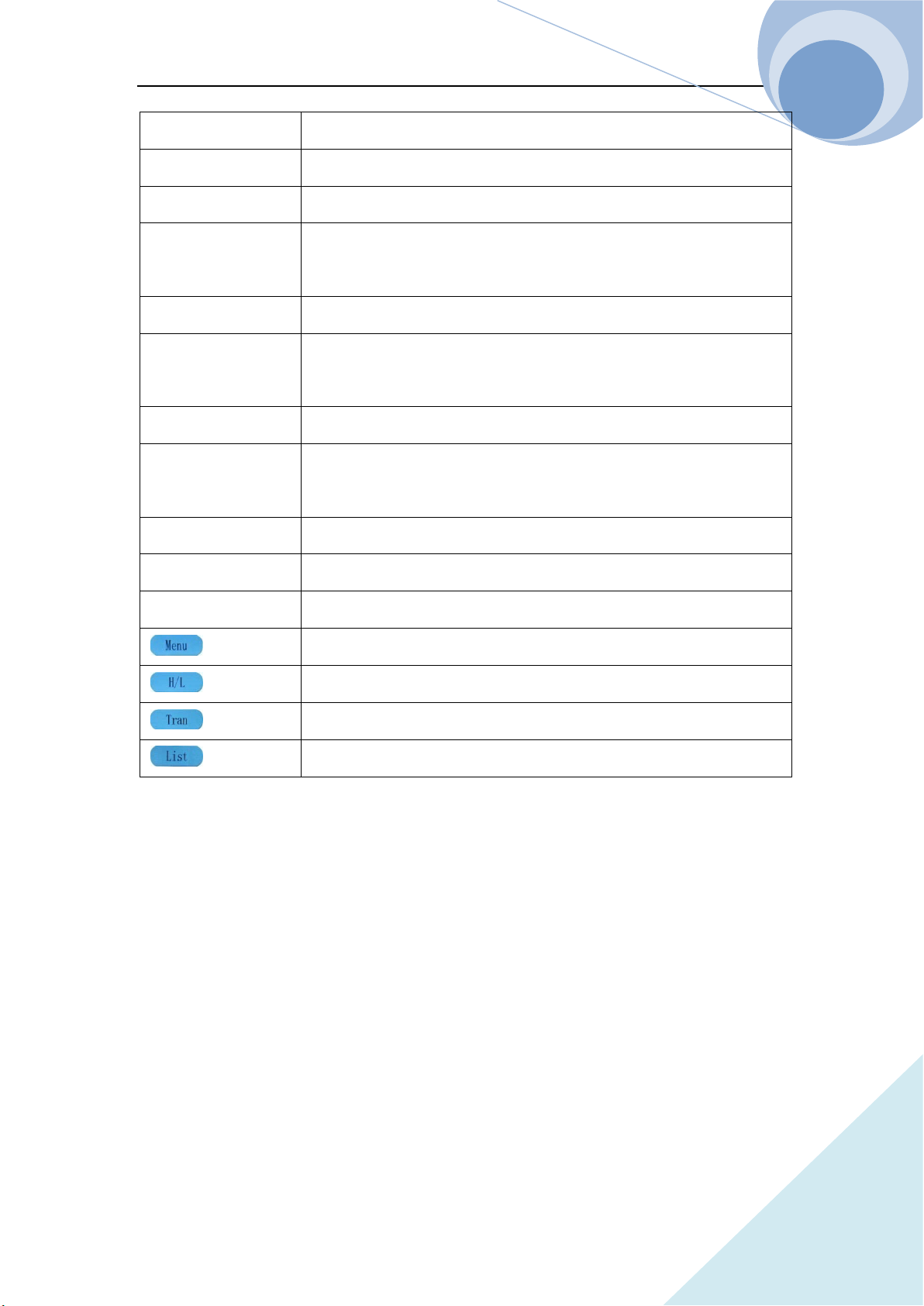
1.6.5.4 CP Mode Menu
Description:In Constant Power Mode, the load units will maintain a constant power by varying
the current. For more details on CR Mode, please refer to Page 58.
Chapter I General Introduction
ARRAY
17
Voltage Value
To display the current input terminal voltage;
Power Value
To display the current power value;
Current Value
To display the current value
Mode
CP indicates constant power mode;
Input State
ON/OFF;
Run Time
To display the time the load being ON, reset when shutdown or
switch mode;
Para Set
To set the constant power value, unit: W;
Start Voltage
To set the start voltage of the load,
0 indicates the function being not enabled;
Pow Limit
To limit the minimum power level at the mode
RiseRate
To control the current rising rate when starting
FallRate
To control the current falling rate when stopping
key
Press this dynamic key to return to the main menu;
key
No function;
key
Press this key to enter the transient operation;
key
Press this key to enter list operation.
Chapter I General Introduction
ARRAY
18
1.6.5.5 +CV Mode Menu
Description:+CV mode can be added to CC, CR and CP mode. For more details on +CV Mode,
please refer to Page 60.
Voltage Value
To display the current input terminal voltage;
Power Value
To display the current power value;
Current Value
To display the current value
Mode
CCL indicates constant current low range;
+CV indicates +constant voltage mode;
Input State
ON/OFF;
Run Time
To display the time the load being ON, reset when shutdown or
switch mode;
Para Set
To set the constant current value, unit: A;
Volt Start
To set the start voltage of the load,
0 indicates the function being not enabled;
Curr Limit To limit the maximum Current level at the mode
RiseRate
To control the current rising rate when starting
FallRate
To control the current falling rate when stopping
key
Press this dynamic key to return to the main menu;
key
Press this key to switch between CCL and CCH;
key
Press this key to enter the transient operation;
key
Press this key to enter list operation.
Chapter I General Introduction
ARRAY
19
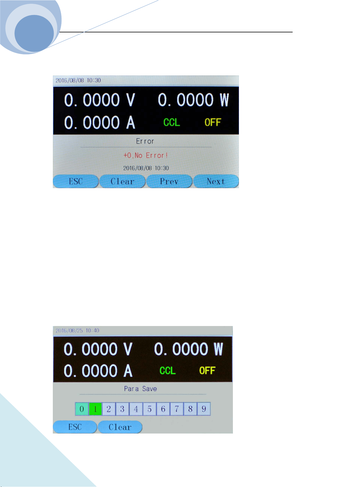
1.6.6 Error & Alarm Menu
When the load appears Alarm & Protection, the LCD will display the corresponding alarm and
protection state. The above diagram is the display of the reverse voltage protection.
The load has the following alarm functions: over current (OC), over voltage (OV), over power
(OP), over temperature (OT), reverse voltage (RV);
And the load has the following protection functions: over current (OC), over power (OP), over
temperature (OT).
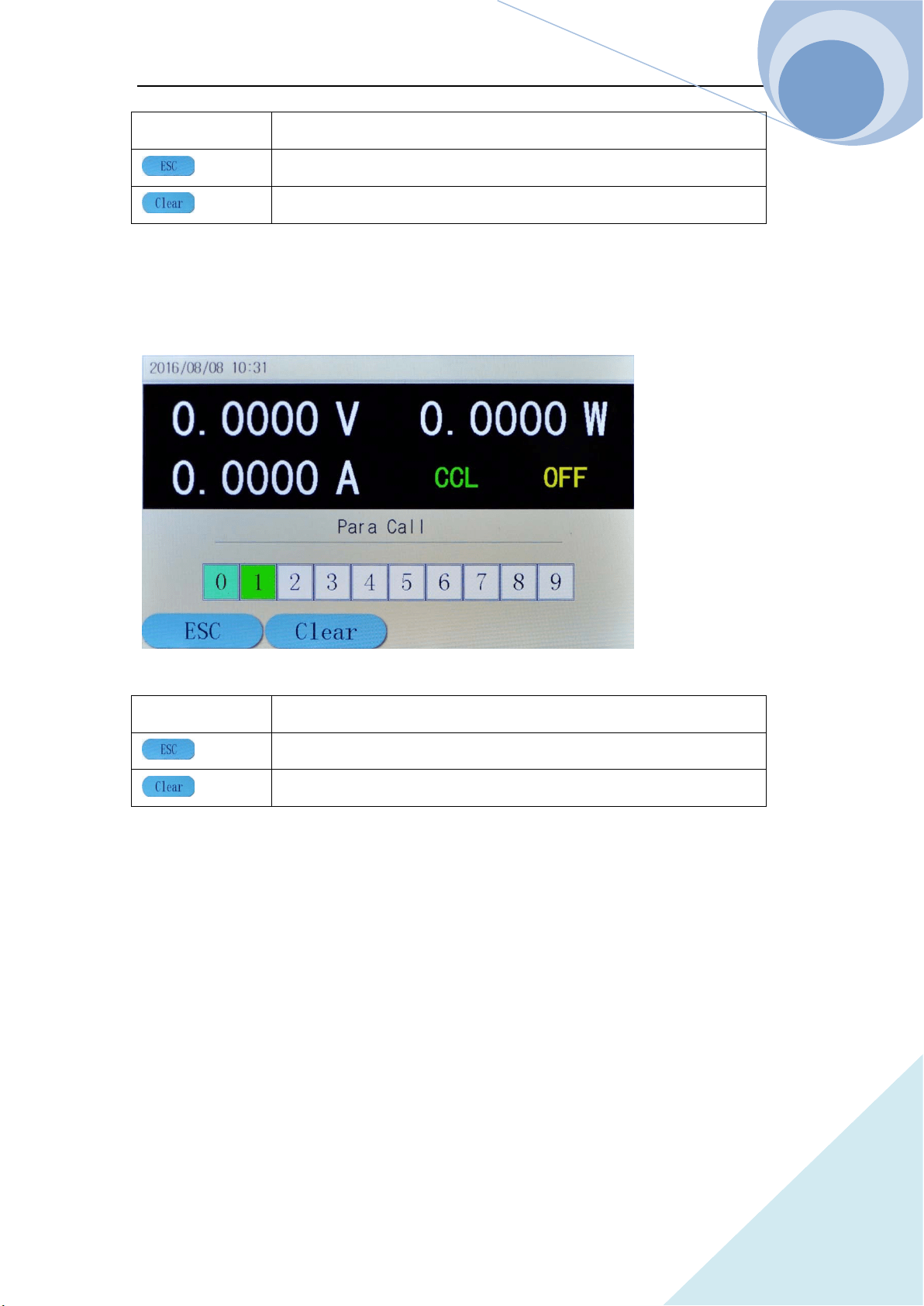
1.6.7 Save Menu
1.6.7.1 Application Save Menu
Chapter I General Introduction
ARRAY
20
Storage Position
(0-9)totally 10
key
Press this dynamic key to return to the main menu;
key
Press this dynamic key to delete the data of the selected position.
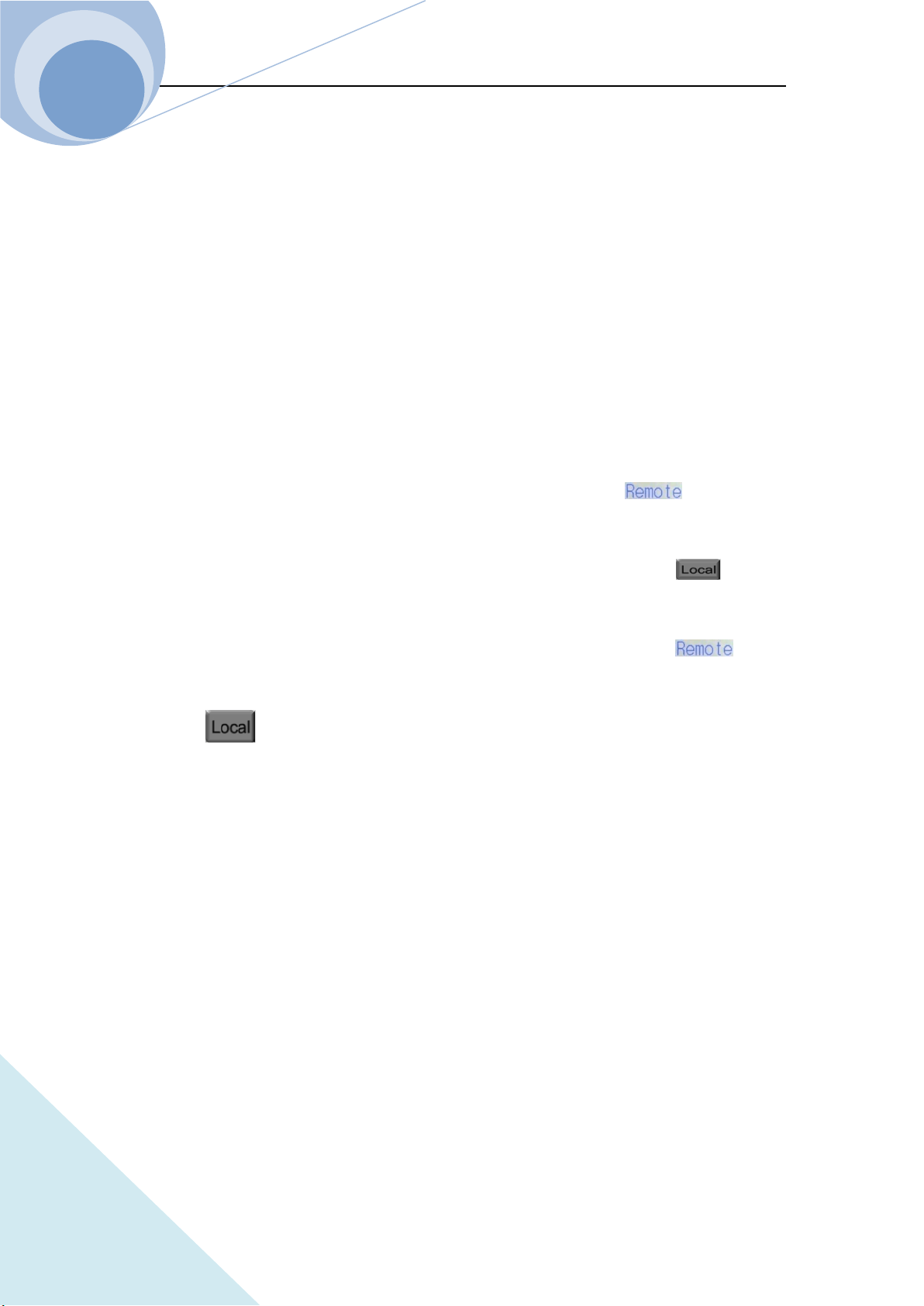
1.6.7.2 Recall Save Menu
Storage Position
(0-9)totally 10
key
Press this dynamic key to return to the main menu;
key
Press this dynamic key to delete the data of the selected position.
1.7 Remote Programming
The commands are sent to the Eload via remote interface (RS232, GPIB or USB), decoded by the
processor and then executed. If there is any error to the commands, the processor can detect the
wrong command and the error type, and can maintain the status register as well.
Chapter II Functions & Features
21
ARRAY
Chapter II Functions and Features
This chapter will mainly introduce the functions and features of the load. After reading this
chapter, you will have a better understanding of ARRAY 375XA Electronic Load.
2.1 Local & Remote Control
ARRAY 375XA Electronic Load can be controlled via the keypad and the knob in the front panel,
or via the remote controller by the remote interface. If the load is needed to be controlled via the
front panel, it has to be in local control status. The load will be in local control status
automatically when it is powered on. When the load receives the remote commands:
SYSTem:REMote via the RS232, USB or GPIB, the LCD will display status and the
load will be turned in remote control status.
Under remote control status, all the operations of the keypads and knob (except key) are
invalid. All operations on the load are controlled by remote controller. After receiving the return
commands: SYSTem:LOCal, the load will return to local control status and the on the
LCD will disappear. In remote control status, you can retun the load to local control status via
pressing key.
Details of local operation are covered in Chapter IV “Local Operation” and details of remote
programming operation are covered in Chapter V “Remote programming Operation”. Complete
programming details are given in 《ARRAY 375XA Electronic Load SCPI Programming Guide》.
2.2 Main Functions
The load can mainly work in the following modes:
Constant Current Mode: CCL, CCH
Constant Voltage Mode: CVL,CVH
Constant Resistance Mode: CRL, CRH
Constant Power Mode: CP
Constant Current + Constant Voltage Mode: CCL+CV, CCH+CV

Chapter II Functions & Features
22
ARRAY
Constant Resistance + Constant Voltage Mode: CRL+CV, CRH+CV
Constant Power + Constant Voltage Mode: CP+CV
Transient Operation: TRAN
List Operation: LIST
2.3 Basic Test Functions
There are four basic test functions: constant current (CC), constant voltage (CV), constant
resistance (CR), constant power (CP) and twelve operation mode: CCL, CCH, CVL, CVH, CRL,
CRH, CP, CCL+CV, CCH+CV, CRL+CV, CRH+CV, CP+CV.
The operation mode and the relative parameters can be set via the front panel or the remote
command. The load will remain in the current mode unless the user changes the settings. If the
input of the load is in ON state, when the mode is changed, the load will be turned off
automatically to avoid the potential impact of current.
The set value of the load will be effective immediately when the load is turned on. If the input set
value exceeds the allowed range, it will be automatically limited at the maximum value or the
minimum value.
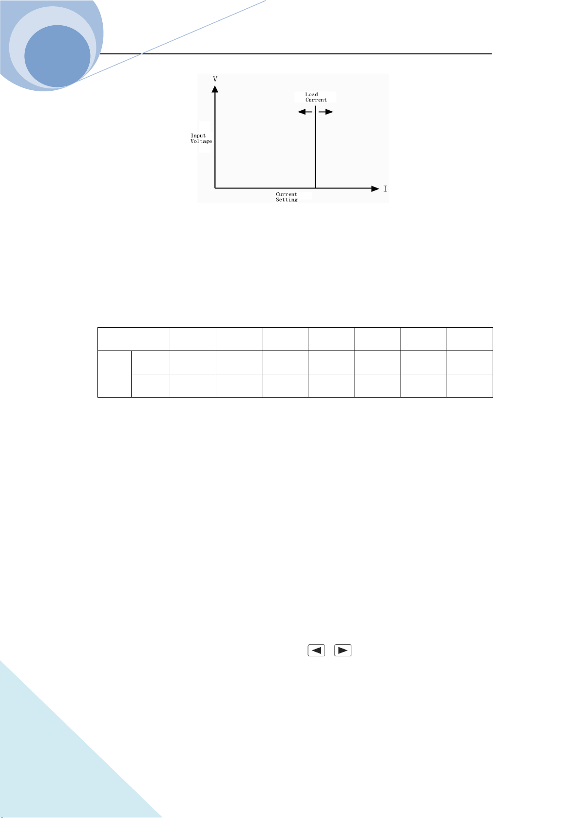
2.3.1 CC Test
Constant current mode have two ranges: the high range (CCH) and the low range (CCL). The high
range provides wider test range, while the low range provides better resolution at low current
settings. In CC mode, the load will sink a constant current in accordance with the programmed
value regardless of the change of input voltage. See Figure 2-1. In basic operation state, press
key to select CCH or CCL constant current mode. Input the current value via number
keys or knob combining with and keys. Then confirm the setting via key. The
CC operation mode and the parameters can be set via remote commands: MODE CCL | CCH
CURRent <NRf+>
Chapter II Functions & Features
23
ARRAY
Figure 2-1 Constant Current Mode
2.3.1.1 Current Setting Range
The setting ranges for the load are listed as follows:
Model
3750A 3751A 3752A 3753A 3754A 3755A 3756A
Mode
CCL
0~6A 0~6A 0~6A 0~6A 0~8A 0~8A 0~8A
CCH
0~100A
0~150A
0~75A 0~160A 0~180A 0~240A
0~260A
If the input of the load is ON, the load will be turned off automatically when the mode is changed.
For example: When the load is switched from CCL to CCH, the input of the load will be off
automatically. Also of note is that the current set level may change with the current set mode and
the changed value is the current value in current mode. For example: the original setting is CCH
150.000A. When the load is switched from CCH to CCL, the current set value will become the
present current value 1A in CCL mode.
2.3.1.2 Immediate Current Level
The immediate current level is the current set value in CC mode, which can be set in parameter set
menu in current mode, or can be set via remote command: CRRRent<NRf+>. In CC mode, the
immediate current level can directly be modified via , or knob.
2.3.1.3 Triggered Current Level
The triggered current level is the preset current value in the load, which will become the

Chapter II Functions & Features
24
ARRAY
immediate current level automatically when a trigger is received. In CC mode, if the input of the
load is ON, the input current will be updated immediately when a trigger occurs. If it is not in CC
mode, the level will not affect the load until the CC mode becomes enabled.
The triggered current value can only be set via remote command: CURRent:TRIGgered <NRf+>.
Once a triggered current level is triggered, the subsequent triggers will have no effect on the input
unless another new triggering signal is sent. The trigger operation will be described in later chapter.
The status register of the load can keep track of pending triggers and other operation conditions,
which will be described in details in 《ARRAY 375XA Electronic Load SCPI Programming
Guide》.
2.3.1.4 Transient Current Level
In transient current operation mode, the load can continuously toggle between the two levels: the
transient level and the immediate level. The transient current level can be set in the transient
operation menu or via the remote command: CURRent: TLEVel <NRf+>.
2.3.1.5 Software Cureent Level
The load allows the user to set a protection current level (the range is the same as that in CCH
mode) via remote command. The load will be turned off with beeping alarms if the software
current level is exceeded beyond a programmable time (0.001~60s). Please note that the
protection current level is valid in any mode (not limited to CC mode) of operation. The remote
commands are listed as follows:
CURRent:PROTection <NRf+>
CURRent:PROTection:DELay <NRf+>
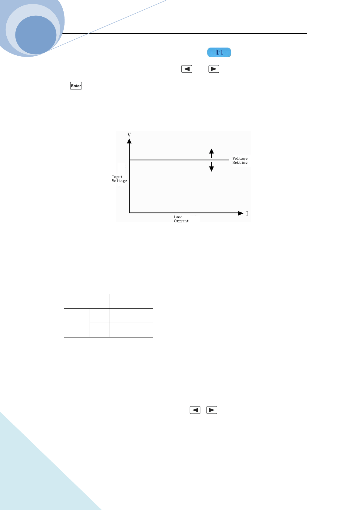
2.3.2 CV test
In CV mode, the load will attempt to sink enough current to control the source voltage to the
programmed constant value regardless the change of the input current. See figure 2-2. In basic
Chapter II Functions & Features
25
ARRAY
operation state, select CVL or CVH mode via dynamic key, then enter the voltage
value via the keypads or knob combining with and keys, finally confirm the setting
with key. The CV mode and the parameters can also be set via the remote commands:
MODE CVL|CVH
VOLTage <NRf+>
Fig. 2-2 CV Mode
2.3.2.1 Voltage Setting Range
The setting ranges of the voltage for the load are listed as follows
Model 375XA
Voltage CVH 0~240V
CVL 0~24V
2.3.2.2 Immediate Voltage Level
The immediate voltage level is the voltage set value in CV mode, which can be set in parameter
set menu in voltage mode, or can be set via remote command: VOLTage<NRf+>. In CV mode, the
immediate voltage level can directly be modified via , or knob.

Chapter II Functions & Features
26
ARRAY
2.3.2.3 Triggered Voltage Level
The triggered voltage level is the preset voltage value in the load, which will become the
immediate voltage level automatically when a trigger is received. In CV mode, if the input of the
load is ON, the input voltage will be updated immediately when a trigger occurs. If it is not in CV
mode, the level will not affect the load until the CV mode becomes enabled.
The triggered voltage value can only be set via remote command: VOLTage:TRIGgered <NRf+>.
Once a triggered voltage level is triggered, the subsequent triggers will have no effect on the input
unless another new triggering signal is sent. The trigger operation will be described in later chapter.
The status register of the load can keep track of pending triggers and other operation conditions,
which will be described in details in 《ARRAY 375XA Electronic Load SCPI Programming
Guide》.
2.3.2.4 Transient Voltage Level
In transient voltage operation mode, the load can continuously toggle between the two levels: the
transient voltage level and the immediate voltage level. The transient current level can be set in the
transient operation menu or via the remote command: VOLTage: TLEVel <NRf+>.
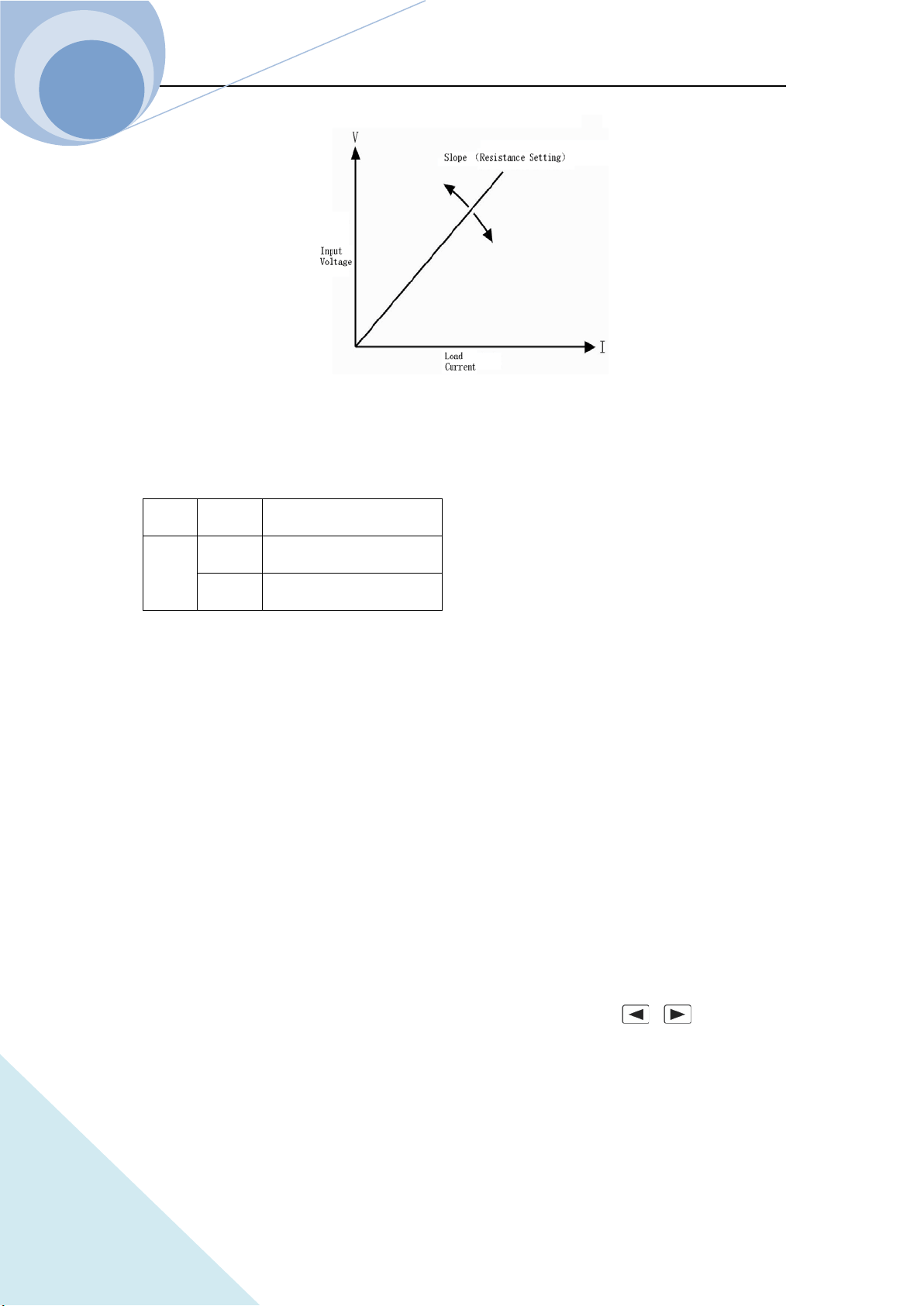
2.3.3 CR Test
There are two operation ranges: CRL and CRH in CR mode. In this mode, the electronic load is
equivalent to a constant resistance, as shown in figure 2-3, and the electronic load will linearly
change the current according to the input voltage to make I=U/R. In basic operation state, press
key to enter the mode and parameter set menu, select CR range via dynamic key,
then enter the resistance value via the keypads or knob combining with and keys,
finally confirm the setting with key. The CR mode and the parameters can also be set via
the remote commands:
MODE CRL | CRH
RESistance <NRf+>
Chapter II Functions & Features
27
ARRAY
Fig. 2-3 Constant Resistance Mode
2.3.3.1 Resistance Setting Range
The setting ranges of the resistance for the load are listed as follows:
Model 375XA
Mode
CRL
0.01Ω~240000Ω
CRH
0.2Ω~2400KΩ
If the input of the load is ON, the load will be turned off automatically when the mode is changed.
For example: When the load is switched from CRL to CRH, the input of the load will be off
automatically. Also of note is that the voltage set level may change with the voltage set mode to be
suitable for the new range. For example: the original setting is CRH 10.000Ω. When the load is
switched from CRH to CRL, the voltage set value will become the minimum voltage value
0.0000Ωin CRL mode.
2.3.3.2 Immediate Resistance Level
The immediate resistance level is the resistance set value in CR mode, which can be set in
parameter set menu in resistance mode, or can be set via remote command: RESistance <NRf+>.
In CR mode, the immediate resistance level can directly be modified via , or knob.
2.3.3.3 Triggered Resistance Level
The triggered resistance level is the preset resistance value in the load, which will become the
Chapter II Functions & Features
28
ARRAY
immediate resistance level automatically when a trigger is received. In CR mode, if the input of
the load is ON, the input resistance value will be updated immediately when a trigger occurs. If it
is not in CR mode, the level will not affect the load until the CR mode becomes enabled.
The triggered resistance level can only be set via remote command: RESistance:TRIGgered
<NRf+>. Once a triggered resistance level is triggered, the subsequent triggers will have no effect
on the input unless another new triggering signal is sent. The trigger operation will be described in
later chapter. The status register of the load can keep track of pending triggers and other operation
conditions, which will be described in details in 《ARRAY 375XA Electronic Load SCPI
Programming Guide》.
2.3.3.4 Transient Resistance Level
In transient resistance operation mode, the load can continuously toggle between the two levels:
the transient resistance level and the immediate resistance level. The transient resistance level can
be set in the transient operation menu or via the remote command: RESistance: TLEVel <NRf+>.
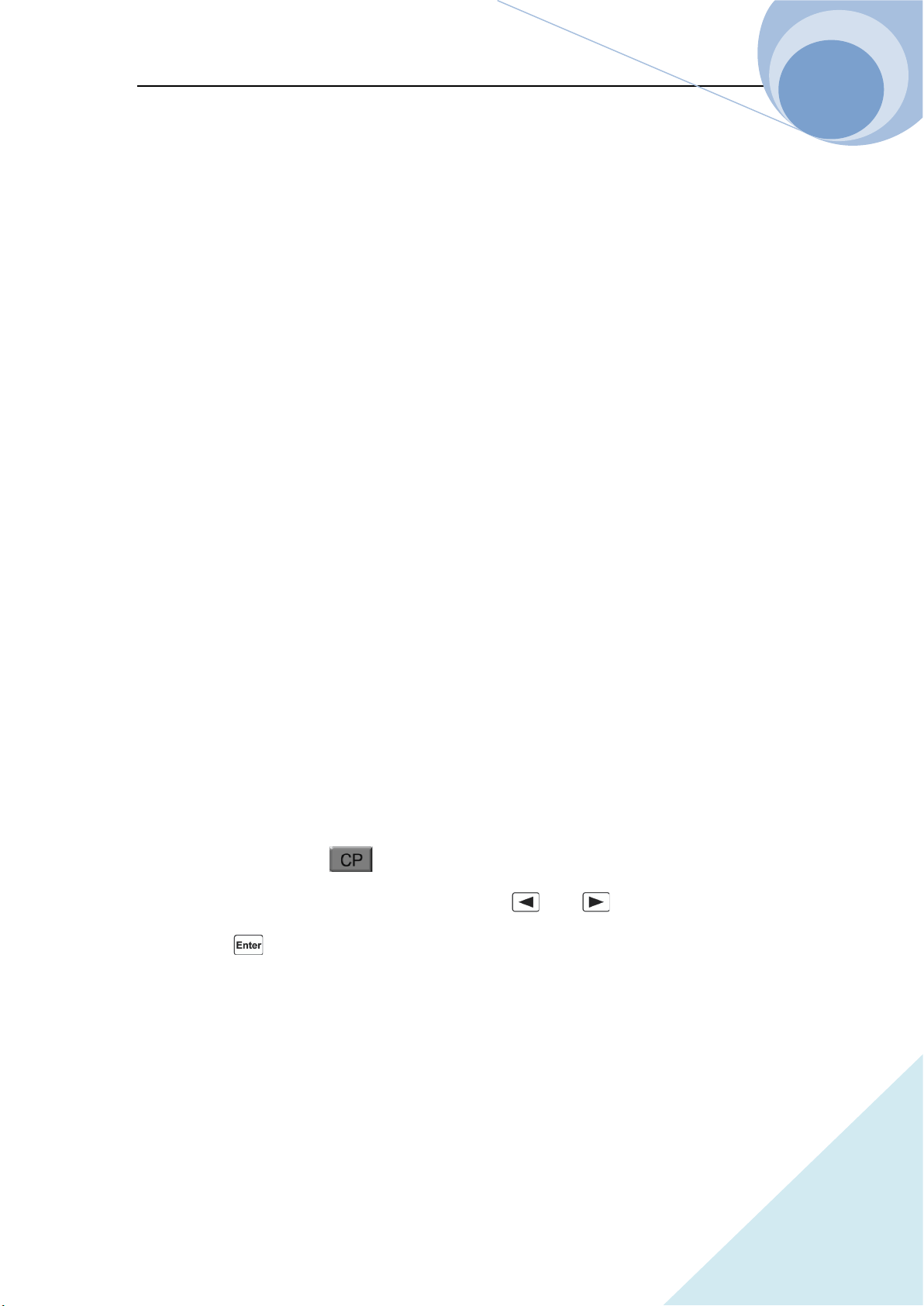
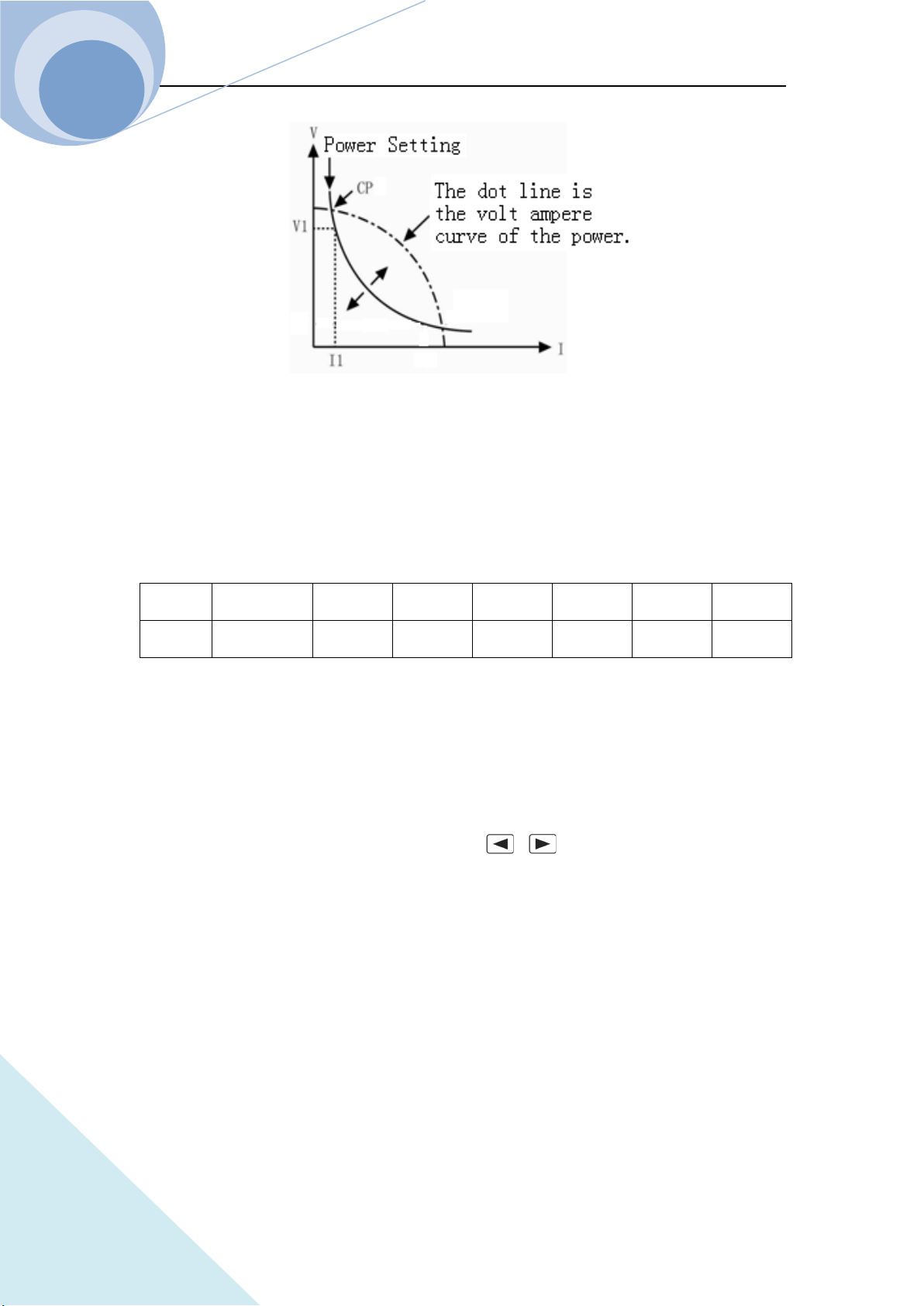
2.3.4 CP Test
The constant power mode is the constant power-voltage source mode, being suitable for the
voltage source test. In CP mode, the load will consume a constant power from the power source
regardless of the external current and voltage change to meet U*I=P, as shown in figure 2-4. In
basic operation state, press key to enter the mode and parameter set menu, then enter the
power value via the keypads or knob combining with and keys, finally confirm the
setting with key. The CP mode and the parameters can also be set via the remote
commands:
MODE CP
POWer <NRf+>
Chapter II Functions & Features
29
ARRAY
Fig. 2-4 Constant Power Mode
2.3.4.1 Power Setting Range
The setting ranges of the power for the load are listed as follows:
Model
3750A 3751A 3752A 3753A 3754A 3755A 3756A
Power
0~
1500W 0~2000W 0~1000W 0~2400W 0~3000W 0~4000W 0~5000W
2.3.4.2 Immediate Power Level
The immediate power level is the power set value in CP mode, which can be set in parameter set
menu in power mode, or can be set via remote command: POWer <NRf+>. In CP mode, the
immediate power level can directly be modified via , or knob.
2.3.4.3 Triggered Power Level
The triggered power level is the preset power value in the load, which will become the immediate
power level automatically when a trigger is received. In CP mode, if the input of the load is ON,
the input power value will be updated immediately when a trigger occurs. If it is not in CP mode,
the level will not affect the load until the CP mode becomes enabled.
The triggered power value can only be set via remote command: POWer:TRIGgered <NRf+>.
Once a triggered power level is triggered, the subsequent triggers will have no effect on the input
unless another new triggering signal is sent. The trigger operation will be described in later chapter.

Chapter II Functions & Features
30
ARRAY
The status register of the load can keep track of pending triggers and other operation conditions,
which will be described in details in 《ARRAY 375XA Electronic Load Programming Guide》.
2.3.5 CC+CV Test
When CC+CV mode is enabled, if the input voltage is more than the limit voltage, no matter how
the input current is changed ,the Eload will always enter the voltage at the limit of the voltage. If
the input voltage is less than the limit voltage, no matter how the input voltage changes, the input
current of the Eload will be always at the setting current.
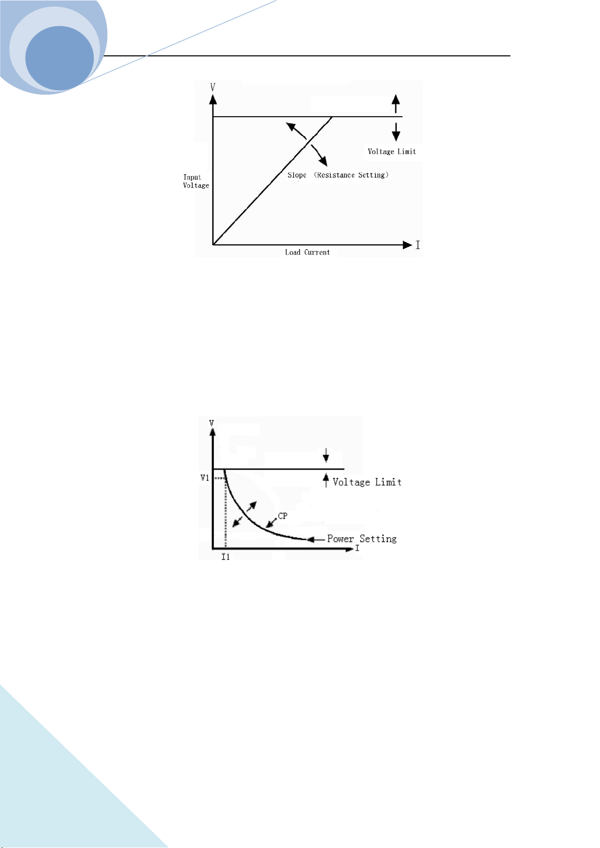
2.3.6 CR+CV Test
When CR+CV mode is enabled, if the input voltage is more than the limit voltage, no matter how
the input current is changed ,the Eload will always enter the voltage at the limit of the voltage. If
the input voltage is less than the limit voltage, no matter how the input voltage changes, the
resistance of the Eload will be always at the setting resistance.
Chapter II Functions & Features
31
ARRAY
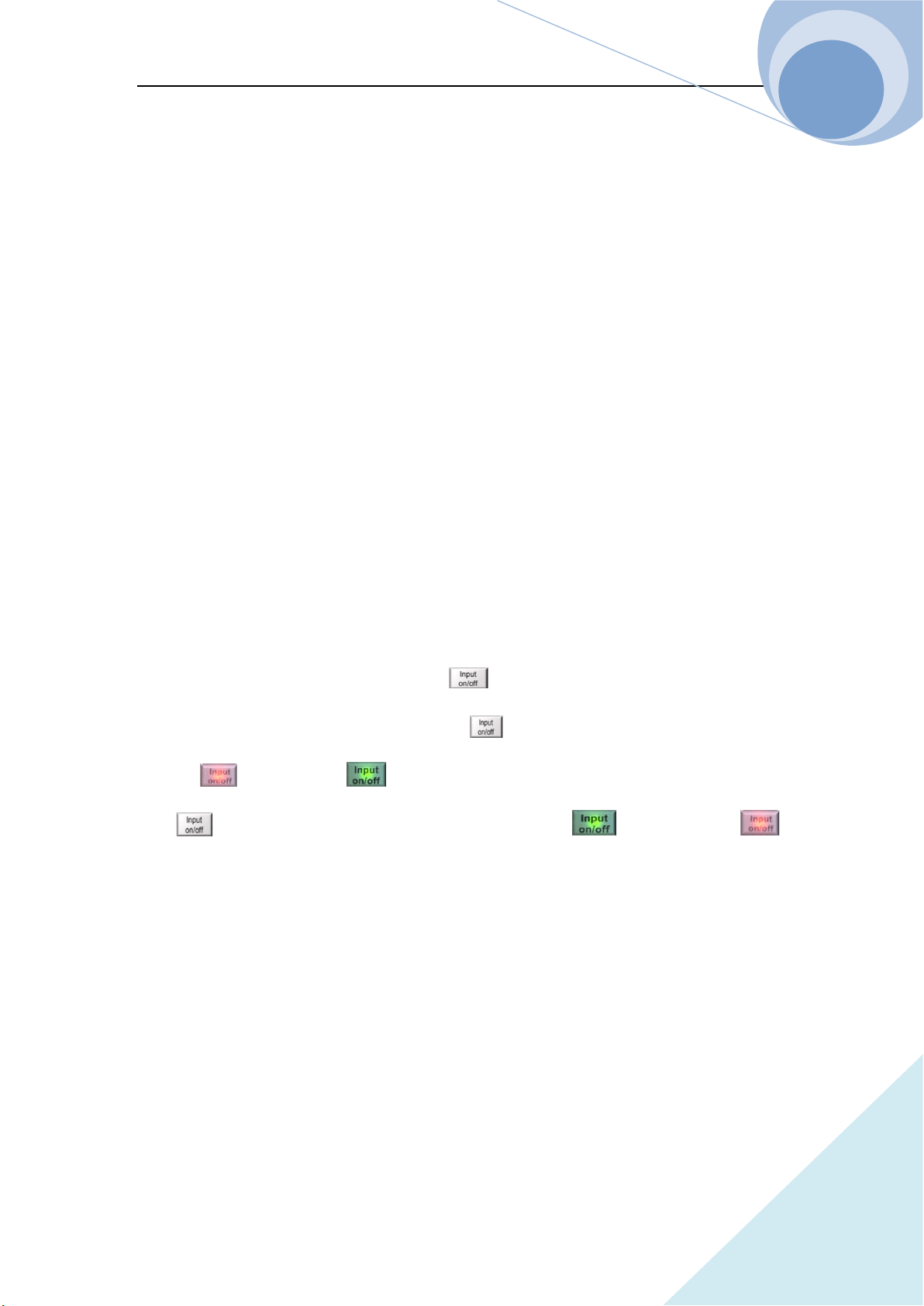
2.3.7 CP+CV Test
When CP+CV mode is enabled, if the input voltage is more than the limit voltage, no matter how
the input current is changed ,the Eload will always enter the voltage at the limit of the voltage. If
the input voltage is less than the limit voltage, no matter how the input voltage changes, the power
of the Eload will be always at the setting power.
2.4 Transient Operation
In transient operation mode, the load can continuously toggle between the two levels: the transient
high level (LevelH) and the transient low level (LevelL), which can be applied to test the dynamic
features of the power source. The transient operation can be executed in CC, CV, CR and CP mode
and there are three operation statuses: Continuous, Pulse and Toggle. Please make sure that the
List Operation function has been turned off before the transient operation.
The transient operation parameters include: transient low level (LevelL), transient high level

Chapter II Functions & Features
32
ARRAY
(LevelH), low level time (TimeL), high level time (TimeH), time for rising edge (TimeR), time for
falling edge (TimeF) and operation mode.
The transient high/low level and the corresponding CC, CV, CR and CP modes share the same
setting ranges.
The range for high/low level time is 10us~10s; the range for rising/falling edge time is 10us~10s;
the time resolution is 10us and the maximum test frequency is 50kHz.
The transient operation can be turned on and off via the dynamic key on the front panel
or the remote command:
SYSTem:STATe TRANsient.
Notes: In transient operation, the VON voltage, the protection current and so on parameter should
be considerate. The improper parameter setting may cause the shut down of the input and thus
interrupt the transient operation.
2.4.1 Continuous Transient Operation
In continuous transient operation, the load periodically toggles between the high/low levels. This
operation is not affected via the trigger signal. The relevant parameters, such as transient low level
(LevelL), transient high level (LevelH), low level time (TimeL), high level time (TimeH), time for
rising edge (TimeR), time for falling edge (TimeF) and operation mode, can be set in transient
operation menu or via the followed remote command:
SYSTem:STATe TRANsient // enter the transient operation mode
CURRent <NRf+> // transient low level
CURRent: TLEVel<NRf+> // transient high level
VOLTage <NRf+>
VOLTage: TLEVel<NRf+>
RESistance <NRf+>
RESistance: TLEVel <NRf+>
TRANsient:LTIMe <NRf+>
TRANsient:HTIMe <NRf+>
TRANsient:RTIMe <NRf+>
TRANsient:FTIMe <NRf+>

Chapter II Functions & Features
33
ARRAY
TRANsient:MODE CONTinuous
For Example: assume that the CCH range is active, the input of the load is OFF, then the transient
parameters should be set as follows:
Press dynamic key to enter into transient operation;
Set the following parameters listed in transient operation menu:
LevelL: 5.000A
LevelH: 10.000A
TimeL: 0.00050s
TimeH: 0.00050s
TimeR: 0.00020s
TimeF: 0.00020s
Mode: Cont
Then press key to turn on the input;
Or via remote command to set:
SCPI Command Description
SYST:STAT TRAN To enter into transient operation mode;
CURR 5 To set the transient current low level to 5A;
CURR: TLEVel 10 To set the transient current high level to 10A;
TRAN:LTIM 0.0005 To set the transient low level time to 0.00050s;
TRAN:HTIM 0.0005 To set the transient high level time to 0.00050s;
TRAN:RTIM 0.0002 To set the time for transient rising edge to 0.00020s;
TRAN:FTIM 0.0002 To set the time for transient falling edge to 0.00020s;
TRAN:MODE CONT To select continuous operation;
INP ON To turn on the input of the load.
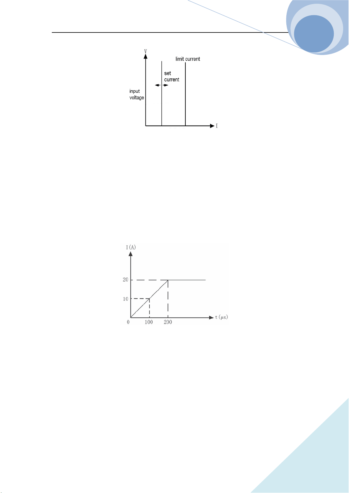
The followed Figure 2-6 show the current waveform of the load: after 200us duration of rising
edge, the load’s input current reaches the transient high level (10A) and remain at 10A for 500us.
Then after 200us duration of falling edge, the input current reaches the transient low level (5A)
and remains at 2A for 500us. Repeat it in cycles.

Chapter II Functions & Features
34
ARRAY
Figure 2-6 Continuous Transient Operation
2.4.2 Pulsed Transient Operation
The trigger function is required for pulsed transient operation. When there is no trigger occurs, the
load remains at the transient low level. After a trigger has been received, a pulse, which is with
three stages: rising edge, transient high level and falling edge, will appear. Then the load returns to
the transient low level again. The associated parameters such as transient low level (LevelL),
transient high level (LevelH), high level time (TimeH), low level time (TimeL), time for rising
edge (TimeR), time for falling edge (TimeF) and pulsed transient mode can be set through
transient operation menu or via the followed remote command.
SYSTem:STATe TRANsient // enter the transient operation mode
CURRent <NRf+> // transient low level
CURRent: TLEVel <NRf+> // transient high level
VOLTage <NRf+> // voltage at transient low level
VOLTage: TLEVel <NRf+> // voltage at transient high level
RESistance <NRf+> // resistance at transient low level
RESistance: TLEVel <NRf+> // time for transient low level
TRANsient:HTIMe <NRf+> // time for transient high level
TRANsient:RTIMe <NRf+> // time for transient rising edge
TRANsient:FTIMe <NRf+> // time for transient falling edge
TRANsient:MODE PULSe // transient operation mode
In order to get a pulse, an explicit trigger is required. The trigger can be produced by the signal
from the external trigger terminal, or via the remote command *TRG. The trigger is effective only
when the load remains at transient low level. Each trigger leads to one pulse. In the duration of the
whole rising edge, transient high level and falling edge, any trigger will be ignored. It is need to

Chapter II Functions & Features
35
ARRAY
do the trigger initial operation before the trigger operation, otherwise the load won’t response to
the trigger.
For example: assume that the CCH range is active, and the input of the load is OFF, then the
transient parameters should be set as follows:
Press dynamic key to enter into transient operation interface;
Set the following parameters in the transient operation menu:
LevelL: 5.000A
LevelH: 10.000A
TimeH: 0.50ms
TimeR: 0.10ms
TimeF: 0.10ms
Mode: Puls
Then press key to turn on the input;
Send the trigger initial command to the load:INIT;
Or set via the remote programming interface:
SCPI Command Description
TRIG:SOUR EXT To select the external trigger input;
SYSTem:STATe TRANsient To enter the transient operation;
CURR 5 To set the transient current low level to 5A;
CURR: TLEVel 10 To set the transient current high level to 10A;
TRAN:HTIM 0.0005 To set the transient high level time to 500us;
TRAN:RTIM 0.0001 To set the time for transient rising edge to 100us;
TRAN:FTIM 0.0002 To set the time for transient falling edge to 100us;
TRAN:MODE PULS To set the pulsed operation mode;
INP ON To open the input of the load;
INIT The initial operation before trigger
Get the trigger by receiving an external trigger signal. Figure 2-7 shows the current waveform of
the load in pulse transient operation before and after being triggered. After the input of the load is
ON, the load starts its operation at the transient low level (5A). For each trigger, after 10 us
duration of rising edge, the load current reaches the high level (10A) and remains at 10A for 500us.

Chapter II Functions & Features
36
ARRAY
Then after 200us duration of falling edge, the current returns to the transient low level (5A).
Fig. 2-7 Pulsed Transient Operation
2.4.3 Toggled Transient Operation
The trigger function is required for toggled transient operation. When there is no trigger occurs,
the load remains at the transient level. After a trigger has been received, a toggle operation will be
executed and the other transient level will be reached after the duration of the rising edge or the
falling edge. The associated parameters such as transient low level (LevelL), transient high level
(LevelH), transient high level (LevelH), time for rising edge (TimeR), time for falling edge
(TimeF) and toggled transient mode can be set through transient operation menu or via the
followed remote command:
CURRent <NRf+> To set the transient current low level;
CURRent:TLEVel <NRf+> To set the transient current high level;
VOLTage <NRf+> To set the transient voltage low level;
VOLTage:TLEVel <NRf+> To set the transient voltage high level;
RESistance <NRf+> To set the transient resistance low level;
RESistance:TLEVel<NRf+> To set the transient resistance high level;
TRANsient:RTIMe <NRf+> To set the time for transient rising edge;
TRANsient:FTIMe <NRf+> To set the time for transient falling edge;
TRANsient:MODE TOGGle To set the toggled operation mode;
The trigger can be produced by the signal from the external trigger terminal, or via the remote
command *TRG. It is need to do the trigger initial operation before the trigger operation,
otherwise the load won’t response to the trigger.
For example: assume that the CCH range is active, and the input of the load is OFF, then the

Chapter II Functions & Features
37
ARRAY
transient parameters should be set as follows:
Press dynamic key to enter into transient operation interface;
Set the following parameters in the transient operation menu:
LevelL: 5.000A
LevelH: 10.000A
TimeR: 0.10ms
TimeF: 0.20ms
Mode: Togg
Then press key to open the input of the load;
Send the trigger initial command to the load:INIT;
Or set via the remote programming interface:
SCPI Command Description
TRIG:SOUR EXT To select the external trigger input;
SYSTem:STATe TRANsient
// To enter the transient operation mode;
CURR 5 To set the transient current low level to 5A;
CURR:TLEVel 10 To set the transient current high level to 10A;
TRAN:RTIM 0.0001 To set the time for transient rising edge to 100us;
TRAN:FTIM 0.0002 To set the time for transient falling edge to 200us;
TRAN:MODE TOGG To select toggled operation mode;
INP ON To turn on the input;
INIT The initial operation before trigger
Get the trigger by receiving an external trigger signal. Figure 2-8 shows the current waveform of
the load before and after being triggered. After the input of the load is ON, the load starts its
operation at the transient low level (5A). For the first trigger, after 10 us duration of rising edge,
the load current reaches the high level (10A) and remains at 10A. When the second trigger is
received and after 200us duration of falling edge, the current returns to the transient low level (5A)
and remains at 5A.In toggled transient operation, the load will switch between the transient low
level and the transient high level when receiving a triggering signal and repeated the toggle in
cycle.

Chapter II Functions & Features
38
ARRAY
Figure 2-8 Toggled Transient Operation
2.5 List Operation
Beside the transient operation, the load provides more flexible list operation, which can make the
load operate according to the preset sequence.
The list operation allows the users to program series of sequence steps and the operation mode,
load’s value, the duration time for each step can be set. The sequence operation can be executed in
the CV, CC ,CR and CP modes. The minimum time duration for each step is 10us and the
maximum one is 99999s (about 27.78 hours). The list operation allows to be executed cyclically
and the cycle time can be set. And different list operations can be chained. After the execution of
one list operation, another list operation will be enabled via the chained connection, expanding the
capacity of the list operation and implementing more complicated test task. The load can store 10
lists, which can contain 50 steps at most.
The associated parameters of the list operation can be edited and set through list operation menu
or via remote command. The load provides convenient list editing function. When the user is
inputting or editing the sequence step, it is easy to check the previous and subsequent steps, and it
is allowed to be modified and deleted, which effectively simplifies the list input operation.
The set value of each step will be saved automatically when exiting from step edit menu. And the
other list parameters will be saved immediately after being edited.
The list operation also can be implemented via the remote command.
Please make sure that the transient operation is OFF before enabling the list operation. Figure 2-9
is a list running diagram of a 5-steps list operation. See Chapter IV 4.8 List Operation for details.

Chapter II Functions & Features
39
ARRAY
Figure 2-9 List Operation
Notes: In list operation, the Von point and the current limit level should be taken into
consideration, which may cause the shut down of the input, thus interrupt the list operation.
2.6 Triggered Operation
The triggered operation is mainly used to keep the load synchronized with other test equipments
or events. The load provides various triggering modes, which can be applied in the following
occasions:
Triggering a preset level
Transfer all pending preset levels to the immediate levels. For the present active mode, the new
level will appear at the input terminal immediately if the input of the load is on. For other modes,
the preset levels will not be effective at the input terminal until the corresponding mode is active.
Triggering a transient pulse
In pulse transient operation, the trigger will generate a transient pulse in accordance with the
present transient parameters.
Triggering a transient toggle
In toggle transient operation, the trigger will make the load switch once between the transient low
level and the transient high level as the preset transient parameters.
Triggering a list operation
In list operation, the trigger will enable the load to start the present list operation.
Three triggering methods are available for remote control: GPIB <GET> signal, the *TRG
command and the TRIGger command. The external trigger input terminal on the front panel can
also be used to trigger as well.
Chapter II Functions & Features
40
ARRAY
The load has three triggering sources: BUS, EXTernal and HOLD.
● The BUS mode: GPIB <GET> signal or the *TRG command is the trigger source.
● The EXTernal Mode: Choose the trigger input terminal of the load as the trigger source. The
input signal at the external trigger input terminal is TTL, and the falling edge signal is
triggered.
● The HOLD: Only the remote command TRIGger[:IMMediate] can be used as the trigger
source. At this time, all other triggering sources including *TRG become invalid.
Notes: The TRIGger:IMMediate command can be used in all three triggering modes. The
triggering sources can only be selected via the remote command TRIGger:SOURce BUS |
EXTernal | HOLD. Please do the trigger initial operation to the load before triggering
operation, otherwise any trigger will be ignored.
2.7 Input Control
2.7.1 ON/OFF of ELoad Input
The input of the load can be turned on/off via key, or via the remote command: INPut ON
| OFF. If the load’s input is in OFF state, press key to turn on the input, and the yellow
indicator turns to green , and the LCD displays ON. If the load’s input is in ON state,
press key to turn off the input, and the green indicator turns to yellow .
Turning on/off the input does not affect the programmed settings.
In local control, if the input is ON, the load’s state can not be switched directly among the basic
modes, the transient operation, the list operation and so on states. When the load switches from
one operation to another operation, the load will be turn off automatically.
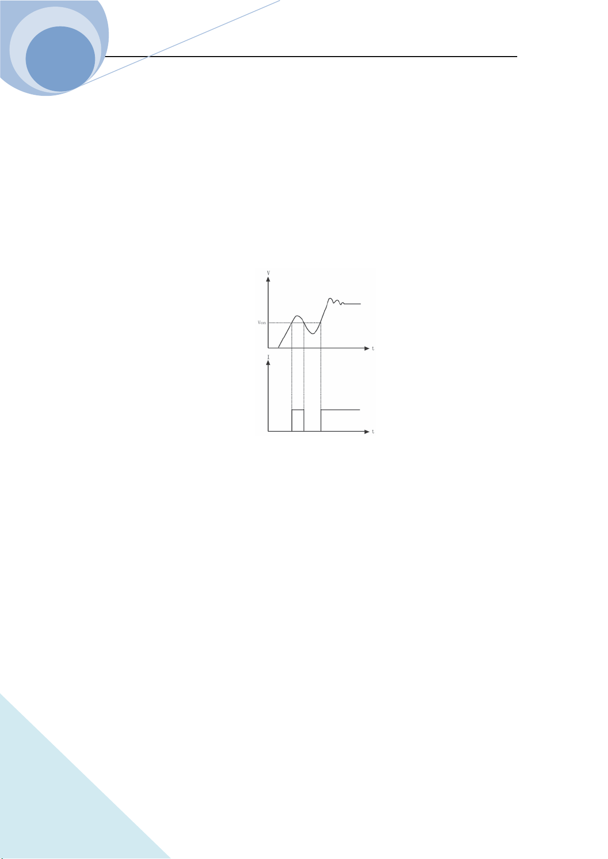
2.7.2 Von Point/Von Latch
When the external input voltage is lower than the Volt Start Point, the load will not be able even
though the input is ON. Only when the external input voltage reaches or exceeds the Von Point,
the load will start to work. The default Von Point is 0V.
Chapter II Functions & Features
41
ARRAY
Von Latch is used to latch the active status of the load. The Volt Start Point being 0V means the
Volt Start Latch function being inactive. If the Volt Start Latch function is needed to be enabled, it
is only need to adjust the Volt Start voltage to the desired set level. When the input voltage
reaches the Volt Start value, the load’s input state is ON. When the input voltage under the Volt
Start value, the load’s input state is OFF. As in figure 2-11, when the Volt Start Point is 0, the
function is disabled. Via setting the Volt Start Point and the Volt Start Latch, the input of the load
can be turned on/off automatically, which greatly simplifies the test operation.
The Volt Start Point can be set in main menu, or via remote command: VOLTage:STARt <NRf+>.
Fig. 2-11 Von Point
2.7.3 Current Limit Function in CV Mode
The current limit function is to limit the maximum set current of the load in CC, CR and CP
modes. If the set current reaches or exceeds the set current level, the load will switch to the CC
mode and run at the limit current, thus to realize limiting the maximum running current as in Fig.
2-13.
The current limit function can be set via the remote command: INPut:LIMit:CURRent <NRf+>.
Chapter II Functions & Features
42
ARRAY
Fig. 2-13 Current Limit Function in CV Mode
2.7.4 Current Rising Rate
Curr Rise Rate is to set the current rising rate in CC, CV and CP modes. It can be set in the main
menu or via the remote command: CURRent:SLEWrate:POSitive <NRf+>.
If the current rising rate is 0.1A/us, and the current set level is 20A, then the current rising rate
diagram is shown as in Figure 2-14 when the input is turned on:
Fig. 2-14 Current Rising Rate
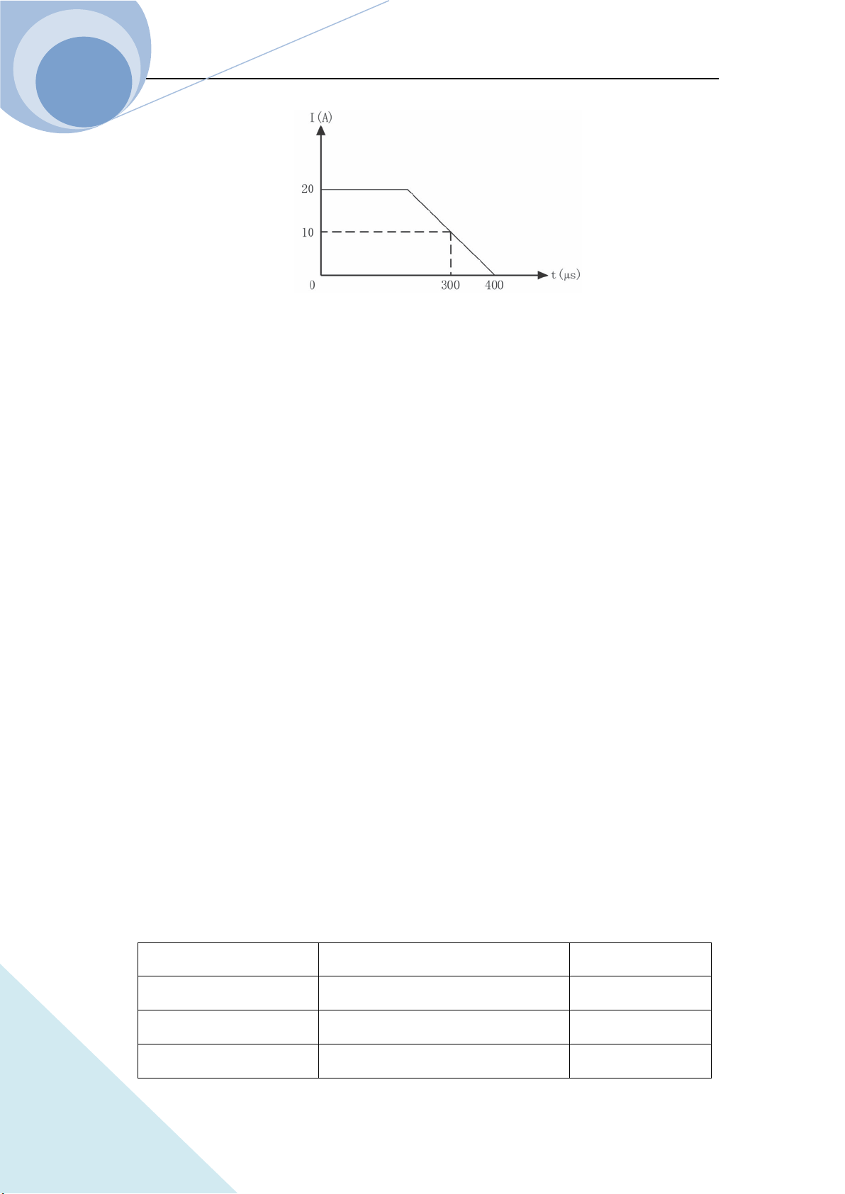
2.7.5 Current Falling Rate
Curr Fall Rate is to set the current falling rate in CC mode. It can be set in the main menu or via
the remote command: CURRent:SLEWrate:NEGative <NRf+>.
If the current falling rate is 0.1A/us, and the current set level is 20A, then the current falling rate
diagram is shown as in Figure 2-15 when the input is turned off:
Chapter II Functions & Features
43
ARRAY
Fig. 2-15 Current Falling Rate
2.8 Measurement Function
The load has high resolution measurement function, which can measure the voltage and the
current in realtime. The input power level and the resistance level can be computed with the input
voltage level and the current level. The measured level can be checked through LCD display
directly or be read via the remote commands:
MEASure:VOLTage?;
MEASure:CURRent?;
MEASure:RESistance?;
MEASure:POWer?
2.9 Saving and Recalling
The load has EEPROM memory, which can be used to save various parameters, such as modes,
input status, current, voltage, resistance, transient settings, protection levels, etc. The 375XA
electronic load can save 10 groups of parameters. All parameters relevant to saving and recalling
operation are listed in Table 2-1 (Take 3751A as an example.).
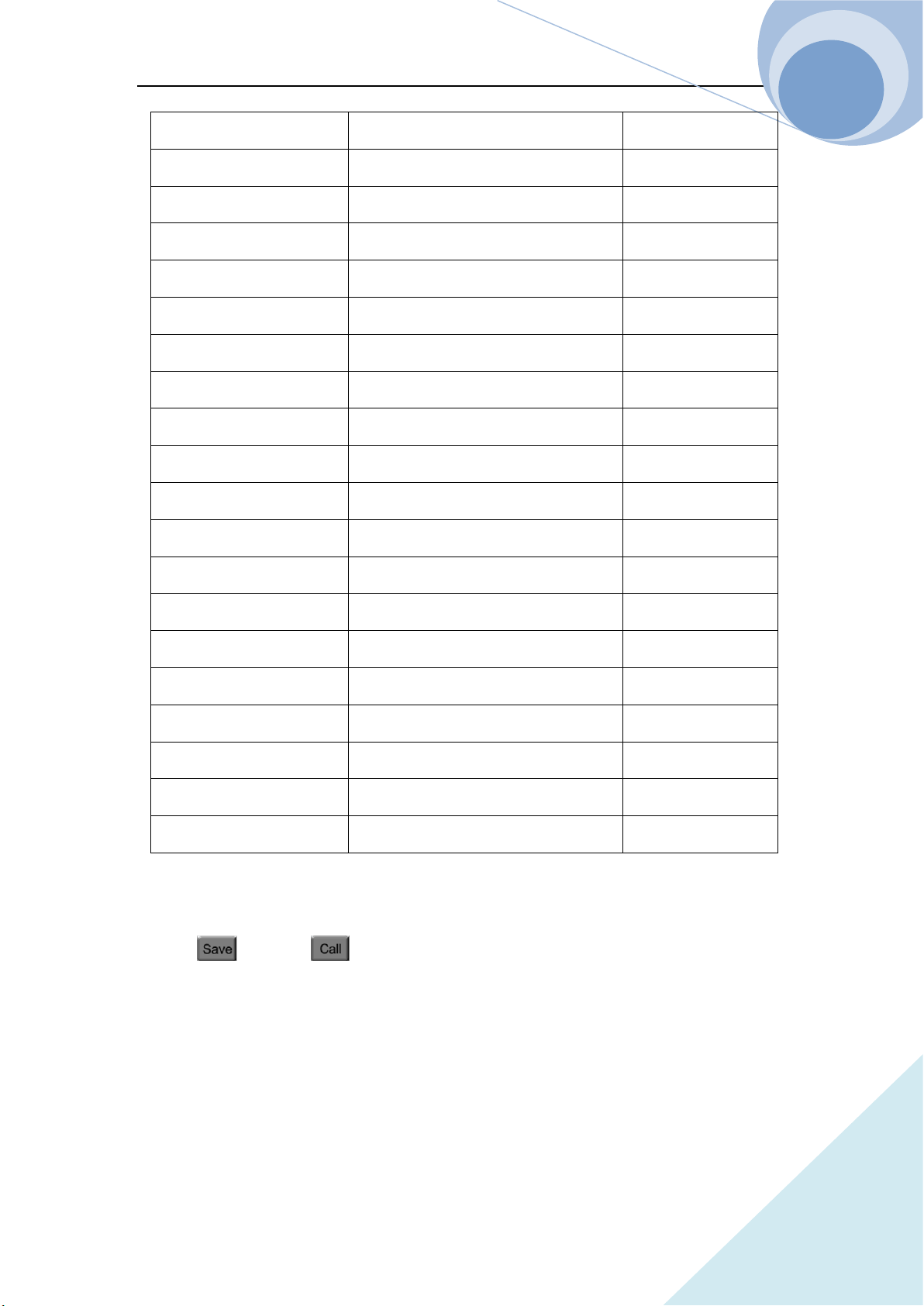
Table 2-1
Function Effect Default
Input Input Status Off
Mode Operation Mode CCH
Current Immediate Current Level 0A
Chapter II Functions & Features
44
ARRAY
Current Rise Rate Current Rising Rate 15A/us
Current Fall Rate Current Falling Rate 15A/us
Current TLEVel Transient Current Level 0A
*Current Protection Level Current Protection Limit 150A
*Current Protection Delay Current Protection Delay 60s
*Current Protection State Enable/Disable Current Protection Off
Voltage Immediate Voltage Level 240v
CV Current Limit Current Limit in CV mode 150A
Voltage TLEVel Transient Voltage Level 240v
Resistance Immediate Resistance Level 2000Ω
Resistance TLEVel Transient Resistance Level 2000Ω
Power level Immediate Power Level 0W
Transient Operation Transient Test Off
Transient Mode Transient Mode Continuous
Transient Htime Time for Transient High Level 0.00001s
Transient Ltime Time for Transient Low Level 0.00001s
Transient Rtime Time for Transient Rising Edge 0.00001s
Transient Ftime Time for Transient Falling Edge 0.00001s
*Trigger Source Trigger Source External
Latch Voltage Level Von Point of the Load 0V
* indicates that it can only be programmed in the remote control.
There are 10 groups of parameters stored in Position 0~9, which can be saved and recalled by
pressing key and key, or via the remote command: *SAV < NRl > and *RCL <
NRl >.
The parameters saved in Position 0 will be recalled automatically every time the load being turned
on.

Chapter II Functions & Features
45
ARRAY
2.10 Read Remote Program Errors
The Err annunciator at the upper right corner on the screen will display the error information when
the remote programming errors occur. The error codes are shown as follows:
-lxx Command errors
-2xx Execution errors
-3xx Device-specific errors
-4xx Query errors
The remote programming errors can be checked in the error code interface by pressing
ERROR key on the front panel or via remote query command: SYSTem:ERRor?.
All the error messages are saved in one error queue, which is a first-in first-out structure
buffer and in which 20 pieces of error messages can be saved. If the error messages exceed
20 the lass error in the error queue will be replaced with -350, “Too many errors”. At this
time the load will not save any additional error message, unless the error messages are read
or deleted. Once the error message is read, it will be deleted from the error queue.
2.11 Status Report
The load has a status reporting register, from which various status conditions of the load can be
queried. The user can confirm which events will be reported through setting the enable register in
the status register group. The registers will be introduced in details in 《ARRAY 375XA
Electronic Load SCPI Programming Guide》.
2.12 Protect and Alarm Function
Load has the following alarm functions:
Over voltage (OV)
Reverse voltage Protection (RV)
Load has the following alarm and protection functions:
Over Current (OC)
Over Power (OP)
Over Temperature (OT)
Chapter II Functions & Features
46
ARRAY
If the load goes wrong, the input will be shut down with beeps, and the LCD will display the
detected conditions and the load will enter into the latched protection status. And the
corresponding state bit in the register will be set. Except some specific operations, the load will
not respond to other commands. For example: If an overtemperature condition has been detected,
the input will be turned off with beeps. And the OT will be shown in the lower right corner of the
LCD and the load will have no response to other operation commands.
2.12.1 Clearing Latched Function
When the load enters the latched protection state, it will not respond to any other commands. It wil
return to normal operation only after clearing the latched protection via compound keys
and , or via the remote command: INPut:PROTection:CLEar. Of course the condition that
cause the latch protection must be cleared, otherwise it will cause the latched protection again
immediately.
In addition, when the software current protection function is enabled, if the overcurrent time does
not exceed the set protection time, the load will display PT to indicate, but the input will not be
turned off. At this time, user can reset the overcurrent time via compound keys and ,
or via the remote command: INPut:PROTection:CLEar.
2.12.2 Overvoltage
The overvoltage alarm level is set at a predetermined voltage, which cannot be changed by the
user. When the voltage exceeds this predetermined voltage, the overvoltage protection will be
enabled, and the input is turned off with OV display. Meantime, the OV and VF status register bits
are set and remain until they are reset and the overvoltage condition is removed.
2.12.3 Overcurrent
The load allows the user to define a current protection limit. When the defined current limit is
exceeded, the input will not be turned off immediately but the overcurrent timer will start to time,
and the display will show PT to indicate the protection status. When the specified delay time is

Chapter II Functions & Features
47
ARRAY
reached, the current protection is triggered, the input will be turned off and the display will show
OC. Meantime, the OC and PS status register bits are set and remain until they are reset and the
overcurrent condition is removed.
The current protection limit function can only be set via following remote commands:
SCPI Command Description
CURRent:PROTection:STATe ON | OFF To turn on/off the current protection limit function
CURRent:PROTection < NRf+> To set the current limit level
CURRent:PROTection:DELay < NRf+> To set the delay time to turn off the input
2.12.4 Overpower
The load has both hardware and software overpower protection function.
Once the input power exceeds the rated maximum power, the hardware power-limit circuit will be
enabled immediately to limit the input power within the allowed range and send the overpower
alarm. Meantime, the load will compute the present actual power. No matter the hardware power
limit circuit is enabled or the software test and compute, when the overpower time exceeds 10S,
the overpower protection will be triggered.
When the overpower protection is enabled, the display shows OP and the buzzer sends alarm.
Meantime, the OP and PS status register bits are set and remain until they are reset and the
overpower condition is removed.
2.12.5 Overtemperature
If the internal temperature of the load is over the safe limit, the overtemperature protection will be
triggered and enabled. The input will be turned off with OT displayed. Meantime, the OT and PS
status register bits are set and remain until they are reset and the overtemperature condition is
removed. In clearing latched function state, it will have to wait till the load cools down to the
normal temperature. When OT alarm appears, please do not turn off the power, the fans in the load
will help to cool the temperature in the load.

Chapter II Functions & Features
48
ARRAY
2.12.6 Reverse Polarity
In case the input DC voltage lines are connected with wrong polarity, the reverse polarity alarm
function will be triggered. The input of the load will be turned off with RV display. Meantime, the
RV and VF status register bits are set and remain until they are reset and the reverse polarity
condition is removed.

Chapter III Installation
49
ARRAY
Chapter III Installation
3.1 Initial Check
After receiving the load, please check if there is any obvious damage that may have occurred
during the shipment. Please keep the original packing materials in case the load has to be returned
to ARRAY in future.
Please confirm that there is no breakage on the keys and knob, that the cabinet and panel surfaces
are free of dents and scratches, and that there is no scratch or crack on the LCD display.
Packing List
1
Main Machine
1
2
Terminal Accessory
2
3
Main Power Cable (region dependent)
1
4
USB Cable
1
5
RS232C Cable
1
6
CD-ROM (User’s manual/Programming Manual)
1
7
Calibration Report
1
3.2 Environment/Installation Location
The load can run at its’ full power within the temperature range of 0°C to 40°C, and at a decreased
power from 40°C to 50°C, otherwise the overtemperature protection will be caused.
Place the load in a location with good ventilation, and keep a distance from the electromagnetic
interference. Do not place the load in the flammable atmosphere.
When being installed in the mounting rack, the space is limited to the height of 4U. The four pads
must be removed. The load must be installed in a location that allows sufficient space in the front
and at the back of the load for adequate air circulation. When load working, the fans cool the load
by drawing in air from the front and exhausting out from the back.
Chapter III Installation
51
ARRAY
3.3 PowerOn/Self-check
A power-on self-test can inspect the basic operations of the load as a preliminary test method for
the load acceptance.
Before powering on the load, please check the AC power-line voltage to make sure that the
voltage of the Toggle Key on the rear panel is the same with the local power supply voltage.
A power-on self-test will occurs automatically after connecting the power-line cord and pressing
the Power Switch (as in the following diagram) on the front panel.
If the unit fails to start up properly or does not turn on, please contact the supplier.
If the load detects an error during the power-on self-test, the error messages will be displayed. The
error messages are as shown in the followings:
Error Code Error Explanation
601 LCD self-test error
603 System ADC test failed
607 Rundown too noisy
608 Keypad self-test error
609 EEPROM checksum failed
630 Temperature test failed
If there is no error being detected, it will enter CCL mode interface as default and the input of the
load is OFF. Then power on the load and execute the following test after thirty-minutes warm up.
Connect the output of a power supply, which is with CV and CC mode, to the load’s input with
correct polarity to execute CCH 5A and CV 5V operations. If the load runs normally, it will draw
the current of 5A or regulate the input voltage to 5V within the allowed tolerance specified in this
manual. Thus it can be concluded that the basic work of the load is normal.
Chapter III Installation
52
ARRAY
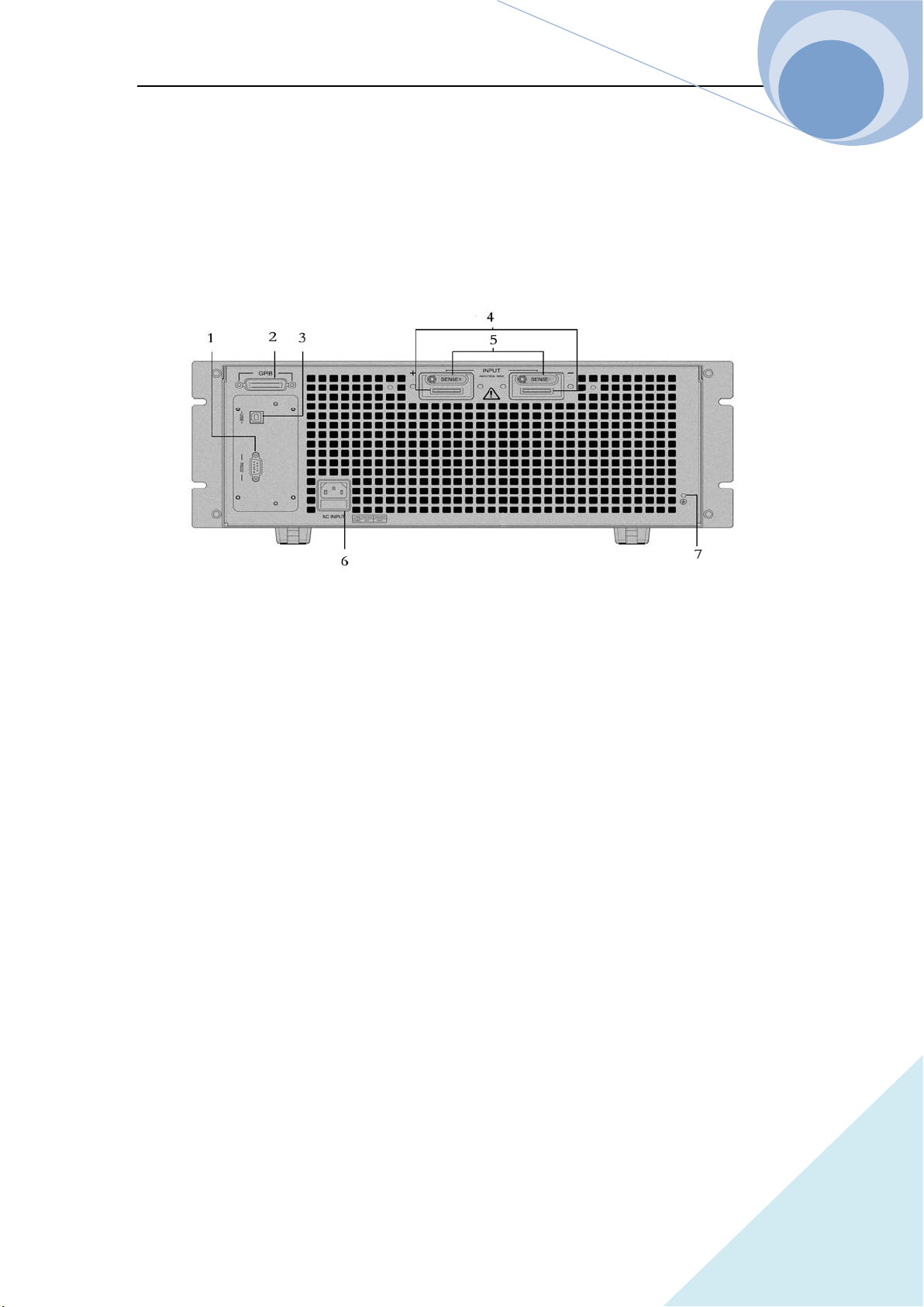
3.4 Connection of the Rear Panel
The rear panel of 375XA Electronic Load is shown as Fig. 3-1, which mainly includes test input
parts, AC input parts and communication interface parts. The AC input parts include AC input
socket, the fuse holder and the voltage toggle key. The communication interface parts include
RS-232 interface, USB interface and the optional GPIB expansion interface.
1. GPIB input socket (Optional)
2. USB input socket
3. RS232C input socket
4. Input terminal, Input (+,-) to connect the being tested components
5. Voltage test terminal, Remote sense(+,-) the connecting port for remote test
6. AC input socket, fuse holder, the voltage toggle key
7. Earthing terminal to connect the system to the earth in rack mounting
1. AC Power Socket, Fuse Holder
AC power cable type needs to meet the local standard of us;
Fuse Specifications: 250V T1A;
Voltage toggle key can select 110V, 120V, 220V and 240V. The selected voltage should be in
accordance with the power voltage in local place.
2. Input Terminal
There are two large copper terminals (INPUT+, INPUT-) one the rear panel, for the input
connection and the maximum diameter of the wire is 6mm. To improve the accuracy of the test

Chapter III Installation
53
ARRAY
and reduce the measurement error, a thick cable is suggested to use in a large current test.
3. Remote Voltage Test Terminal
There are two remote voltage test terminals (SENSE+, SENSE-) one the rear panel, for the remote
voltage test to prevent the affect on the voltage test of the voltage drop of the load input wiring
and to improve the accuracy of the voltage measurement. ARRAY 375XA Electronic Load can
detect the remote voltage input signal automatically, and it is unnecessary to modify the parameter
settings or change the hardware wiring in remote voltage test.
4. Communication Interfaces
RS-232 interface
The load provides an RS-232 interface, which is a standard DB9 pin connector, and uses the DTR
and DSR signals for flow control. The RS-232 Connector Pins is as below:
Pin Input/Output Description
1 - No connection
2 Input RXD, receive data
3 Output TXD, transmit data
4 - No connection
5 Common GND, signal ground
6 - No connection
7 - No connection
8 - No connection
9 - No connection
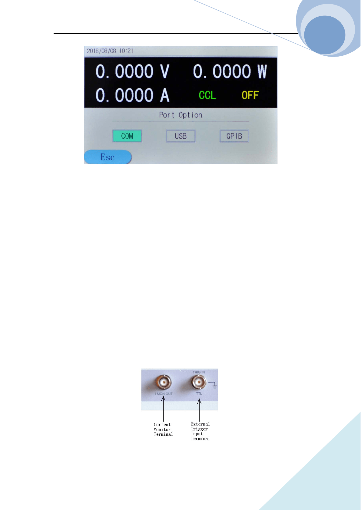
The interface parameters can be set in the Com Port Configuration Menu as in the following
diagram, and you can use SCPI language for programming to realize the communication with the
load.
Chapter III Installation
54
ARRAY
GPIB interface
The load provides a GPIB interface, whose address can be set in the range from 0 to 30 in the port
configuration menu. When multiple GPIB devices are connected, the address of the GPIB for each
device should be unique and cannot be used by other devices on the BUS. The factory default
address of the load is set to 05.
USB interface
User needs to install the corresponding software in PC to communicate with the load.
5. Earthing Terminal
Connect the system to the earth in rack mounting.
3.5 Connection on the Front Panel
The connection terminals of 375XA electronic load on the front panel include the external trigger
input terminal and the current monitoring output terminal, as shown in Fig. 3-2.
Fig. 3-2

Chapter III Installation
55
ARRAY
1. The external trigger input terminal is a BNC connecting terminal, in which the middle part is
input + and the outer case is the input-. It receives 5V TTL-compatible falling-edge trigger
signals. In order to get a reliable trigger, the duration time of low level hold be longer than
10us.
2. The current monitoring output terminal: when connecting the oscilloscope, it can monitor the
realtime state of the current (The terminal and the communication terminal share the common
ground, and the terminal has the insulation voltage 3000VAC with the load input terminal.).
3.6 Wiring
Description: The rear panel input terminals accept up to M8-sized crimped terminal and equipped
with a pairs of lugs.
Procedures:
1. Turn off the power;
2. Turn off the DUT power;
3. Connect the load wires to the input terminal:
Connect the positive (+) terminal on the load module to the high potential output of the
DUT.
Connect the negative (-) terminal on the load module to the low potential output of the
DUT.
Wiring
Wire Gauge (AWG): Before connecting the unit to the power source, the wire gauge must be
taken into account. The load wires must be large enough to resist the overheating when a
short-circuit condition occurs as well as to maintain a good regulation. The size, polarity and
length of a wire are all factors in determining if a wire will withstand short circuit. Wires that are
selected must be large enough to withstand a short circuit and limit voltage drops to no more than
1V per wire. Use the table below to help make a suitable selection.
Load wiring AWG table:
AWG Gauge Diameter (Unit:
mm)
Ohms Per km(Ω/km) Max Amps for Classis
wiring

Chapter III Installation
56
ARRAY
0000 11.684 0.16072 380
00 10.4038 0.2027 328
00 9.26529 0.25551 283
0 8.25246 0.32242 245
1 7.34822 0.40639 211
2 6.54304 0.51266 181
3 5.82676 0.64616 158
4 5.18922 0.81508 135
5 4.62026 1.02762 118
6 4.1148 1.29593 101
7 3.66522 1.6341 89
8 3.2639 2.0605 76
9 2.90576 2.59809 64
10 2.58826 3.2764 55
11 2.030378 4.1328 47
12 2.05232 5.20864 41
13 1.8288 6.56984 35
14 1.62814 8.282 32
Load Line Inductance: When using 375XA, voltage drop and voltage generated due to load line
inductance and current change must be taken into consideration. Extreme changes in voltage may
exceed the minimum or maximum voltage limits, which may damage the 375XA load.
To determine the voltage generated, the following equation can be used.
E=L×(∆I/∆T)
E=voltage generated
L=load line inductance
∆I=change of current(A)
∆T=time(us)
Load line inductance (L) can be approximated as 1uH/meter of wire. (∆I/∆T) is the slew rate in
A/us
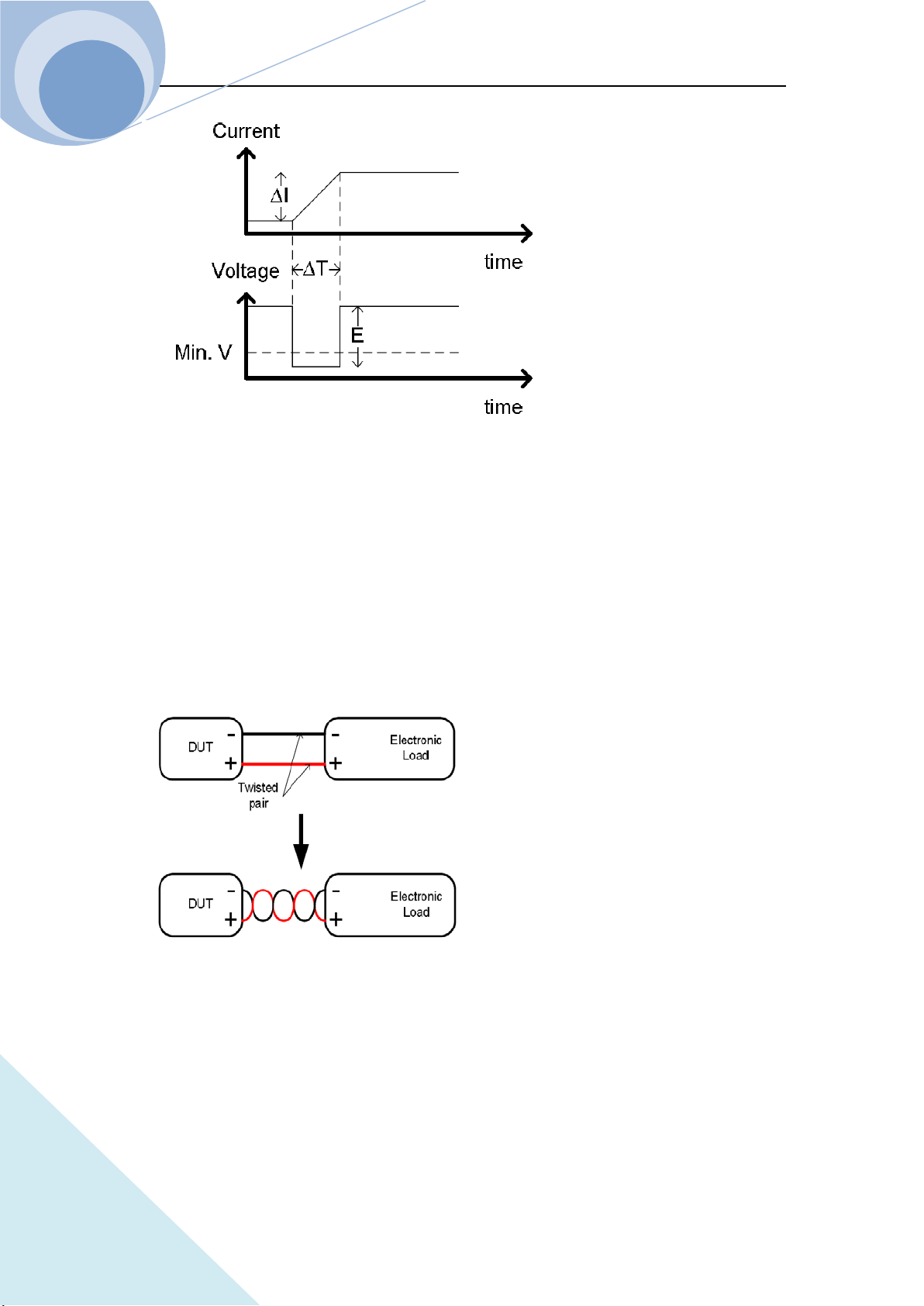
Chapter III Installation
57
ARRAY
The diagram above shows how changes in current can affect voltage.
Load line inductance can be reduced in two ways:
1. Ensure load wires being as short as possible;
2. Twist the positive and negative load wires together.
Current change can be limited by limiting the slew rate or response speed when switching in CR
and CC mode.
Load Wire Connections
The input terminal of the load is on the rear panel. Strictly follow the procedure below for all the
load connections to ensure the safety of the personal and the instrument. Ensure the polarity is
correct before proceeding with any connection. Ensure the maximum input voltage is less than
240V.
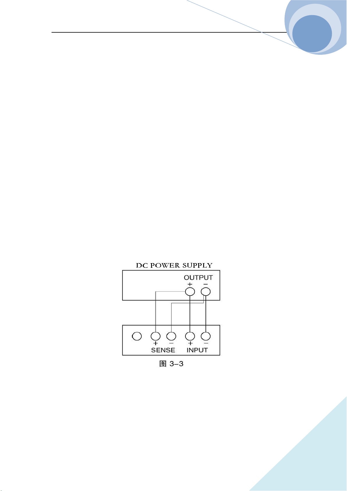
Chapter III Installation
58
ARRAY
Using the wrong polarity, when the reverse voltage is greater than -.3V, the reverse voltage alarm
function will be tripped.
Do not touch any of the input terminals when the unit is on.
Connecting the input terminal to the wrong polarity can damage the DUT and load.
Remote Detecting Connection
When the current flows through the load, the voltage between the input terminals is lower than the
output voltage due to the resistance of the wire connecting the power supply and the load. The
remote voltage detecting terminals can be used to get a more accurate voltage of the power supply.
The load will switch to the remote detecting state after the connection. Remote sense can be used
to help compensate for long cable length. The longer the cable, the higher the potential resistance
and inductance, therefore a short cable is best. For large inductance wire, twist the positive and the
negative load wires together can help to reduce the induced inductance, or use Vsense terminal to
compensate the voltage drop seen across the load leads, especially leads with higher resistance.
This is useful in CV, CP and CR mode. The wiring is as shown in Fig. 3-3.
Parallel Load Connections
When a larger power or current is need, two or more units can be operated in parallel.
Notes: Parallel operation can only be used in CC, CR and CP mode.
Please refer to Fig. 3-4 for the parallel connection wiring method.
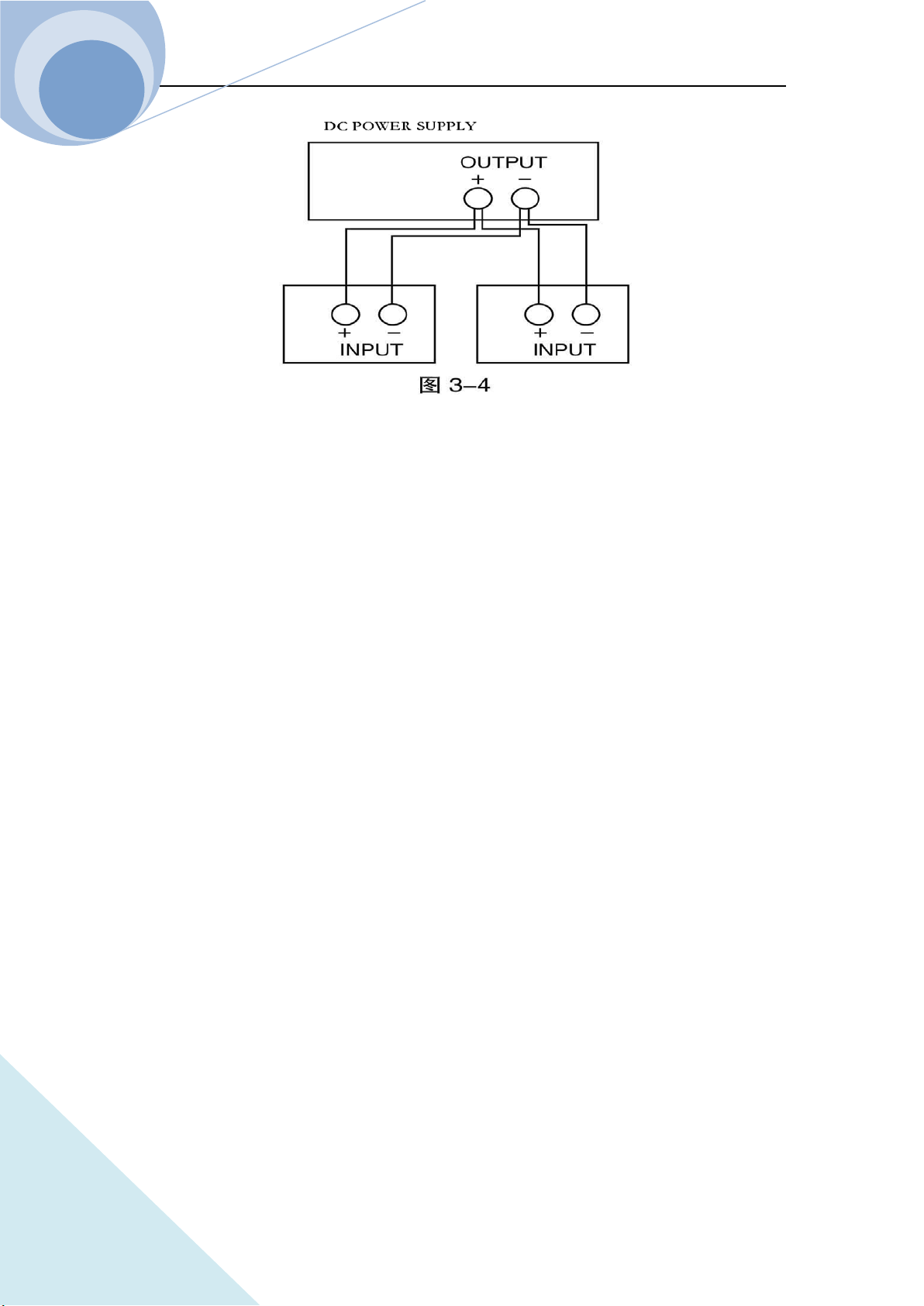
Chapter III Installation
59
ARRAY

Chapter IV Local Operation
60
ARRAY
Chapter IV Local Operation
Chapter II Functions & Features briefly introduced the local operation of the load. This chapter
will explain the local operation in details with examples.
4.1 Local Control
If it is needed to control the load from the front panel, the load must be in local control status. The
load enters into local control status when it is powered on. The relevant parameter preset and
saved in EEPROM Location 0 will be recalled automatically.
In remote control status, all operations on the front panel and the knob are invalid (except ).
When the load receives a remote command: SYSTem:REMote via RS232, USB or GPIB, the
remote control goes into effect and the REM annunciator on the right upper corner turns on.
In remote control status, all operations of the load is controlled via the remote control. After
receiving the return command: SYSTem:LOCal, the load will return to local control and the REM
annunciator will turns off. Or you can return the load to local control by pressing key.
4.2 Main Operation of the Front Panel
Connecting to the power supply
Turning on/off the input
CC Mode
CV Mode
CR Mode
CP Mode
Continuous Transient Operation
Pulsed Transient Operation
Toggled Transient Operation
List Operation
Saving and Recalling Parameters
Clear Protection Settings
Error Messages
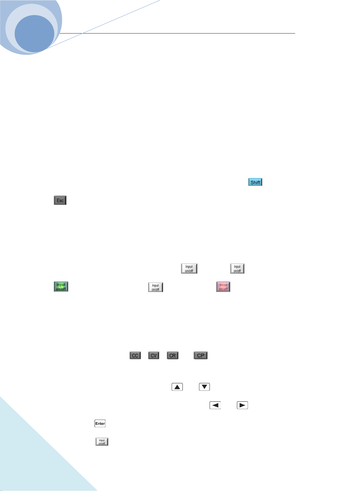
Chapter IV Local Operation
61
ARRAY
Trigger Operation
Main Menu
4.3 Connecting to the Power Supply
Connect the positive pole of the power supply to the red terminal “+” of the input (INPUT) on the
rear panel, and connect the negative pole of the power supply to the black terminal “-” of the input
(INPUT) on the rear panel. If the input is connected reversely, the RV protection status of the load
will become effective. In this case, please re-connect the power supply and the electronic load.
After correctly connecting the power supply and the electronic load, press the key and the
key to clear the RV protection status or restart the load. The details will be described in
“Clearing Protection Settings” as below.
4.4 ON/OFF of the Eload Input
The load can be turned on and off by pressing key. The key will be green
when the load is ON and then key will be orange when the load is OFF.
4.5 Basic Operation
The operation procedures of the basic test is as follows:
1. Press function key , , , or to enter the mode and parameter
setting menu;
2. Select the setting parameter by using and keys;
3. Enter the set value via number keypad, or knob with and keys;
4. Press key to confirm;
5. Press key to open the input of the load.
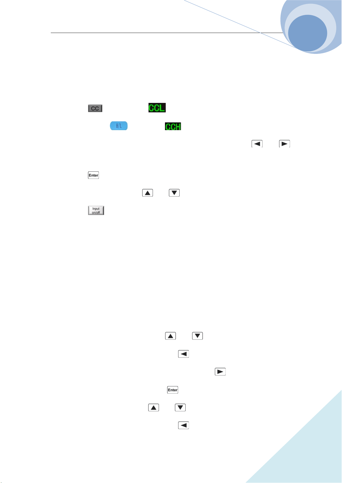
Chapter IV Local Operation
62
ARRAY
4.5.1 CC Mode
CC mode has two ranges: the high range (CCH) and the low range (CCL).
Example 1: Take 3751A as an example, in CVL mode, set the load as CCH mode, the current
level is 80A. Turn on the load. The procedures are shown as below:
Step 1: Press key to enter into mode and parameter setting menu;
Step 2: Press dynamic key to select mode;
Step 3: Enter the current level 80.000 by the number keypad, or via knob with , and
keys;
Step 4: Press key to confirm;
Step 5: Switch to other optional via and keys;
Step 6: Press key to open the load.
The corresponding SCPI commands of the above procedures should be as follows:
MODE CCH ; Set the mode
CURR 80 ; Set the current level
INP ON ; Turn on the load
Example 2: In CCH mode, set the current level to 16A, the current rising rate to 0.1A/us, the
current falling rate to 0.5A/us, the VON voltage to 10V and the current limit level 25A. Turn on
the load. The procedures are shown as below:
Step 1: Switch to parameter setting menu via and keys;
Step 2: Move the cursor to the ten position via the key, then enter number 1 via the knob or
the number keypad; move the cursor to the digit position via the key, then enter number 6
via the knob or the number keypad; then press key to confirm;
Step 3: Switch to Volt Start option via and keys;
Step 4: Move the cursor to the ten position via the key, then enter number 1 via the knob or

Chapter IV Local Operation
63
ARRAY
the number keypad; move the cursor to the digit position via the key, then enter number 0
via the knob or the number keypad; then press key to confirm;
Step 5: Switch to current limit option via and keys;
Step 6: Move the cursor to the ten position via the key, then enter number 2 via the knob or
the number keypad; move the cursor to the digit position via the key, then enter number 5
via the knob or the number keypad; press key to confirm;
Step 7: Switch to current rising rate option via and keys;
Step 8: Move the cursor to the digit position via the key, then enter number 0 via the knob
or the number keypad; move the cursor to the tenth position via the key, then enter number
1 via the knob or the number keypad; press key to confirm;
Step 9: Switch to current falling rate option via and keys;
Step 10: Move the cursor to the digit position via the key, then enter number 0 via the knob
or the number keypad; move the cursor to the tenth position via the key, then enter number
5 via the knob or the number keypad; press key to confirm;
Step 11: Press key to open the load.
Notes: The knob changes the set value immediately. While using the number keypad, the
key is needed to press to confirm. Otherwise the operation will be invalid. When the
load is open, the set value will be valid in the input terminal immediately.
The corresponding SCPI commands of the above procedures should be as follows:
MODE CCH // Set the mode
CURR 16 // Set the current level
CURR:SLEW:POS 0.1 // Set the current rising rate 0.1A/us
CURR:SLEW:NEG 0.5 // Set the current falling rate 0.5A/us
VOLT:STAR 10 // Set the VON voltage 10V
CURR:LIM 25 // Set the current limit 25A
Chapter IV Local Operation
64
ARRAY
INP ON // Open the load
Notes: In CCH or CCL status, the or the will be displayed at the lower right
corner.
4.5.2 CV Mode
Example 1: Take 3751A as an example, in CCH mode, set the load as CVH mode, the voltage
level is 50V. Turn on the load. The procedures are shown as below:
Step 1: Press key to enter into mode and parameter setting menu;
Step 2: Press dynamic key to select mode;
Step 3: Enter the voltage level 50 by the number keypad, or via knob with , and keys;
Step 4: Press key to confirm;
Step 5: Press key to turn on the load.
The corresponding SCPI commands of the above procedures should be as follows:
MODE CVL ; Set the mode
CURR 50 ; Set the voltage level
INP ON ; Turn on the load
Example 2: In CVH mode, set the voltage level to 60V, the Volt Start to 20V, the voltage limit to
100V, the voltage rising rate 20V/us and the voltage falling rate 24V/us. Turn on the load. The
procedures are shown as below:
Step 1: Switch to parameter setting menu via and keys;
Step 2: Move the cursor to the ten position via the key, then enter number 6 via the knob or
the number keypad; move the cursor to the digit position via the key, then enter number 0
via the knob or the number keypad; then press key to confirm;
Step 3: Switch to Volt Start option via and keys;
Step 4: Move the cursor to the ten position via the key, then enter number 2 via the knob or
Chapter IV Local Operation
65
ARRAY
the number keypad; move the cursor to the digit position via the key, then enter number 0
via the knob or the number keypad; then press key to confirm;
Step 5: Switch to voltage limit option via and keys;
Step 6: Move the cursor to the hundred position via the key, then enter number 1 via the
knob or the number keypad; Move the cursor to the ten position via the key, then enter
number 0 via the knob or the number keypad; move the cursor to the digit position via the
key, then enter number 0 via the knob or the number keypad; press key to confirm;
Step 7: Switch to voltage rising rate option via and keys;
Step 8: Move the cursor to the ten position via the key, then enter number 2 via the knob or
the number keypad; move the cursor to the digit position via the key, then enter number 0
via the knob or the number keypad; press key to confirm;
Step 9: Switch to voltage falling rate option via and keys;
Step 10: Move the cursor to the ten position via the key, then enter number 2 via the knob
or the number keypad; move the cursor to the digit position via the key, then enter number
4 via the knob or the number keypad; press key to confirm;
Step 11: Press key to open the load.
Notes: The knob changes the set value immediately. While using the number keypad, the
key is needed to press to confirm. Otherwise the operation will be invalid. When the
load is open, the set value will be valid in the input terminal immediately.
The corresponding SCPI commands of the above procedures should be as follows:
MODE CVH ;Set the mode
VOLT 60 ;Set the voltage level
VOLT:SLEW:POS 20 ;Set the voltage rising rate 20V/us
VOLT:SLEW:NEG 24 ; Set the voltage falling rate 24V/us
VOLT:STAR 20 ;Set the VON voltage 20V
Chapter IV Local Operation
66
ARRAY
VOLT:LIM 100 ;Set the voltage limit level 100V
INP ON ;Open the load
Notes: In CV mode, the green will be displayed in the LCD.
Example 3: Take 3751A as an example, in CCH mode, set the load to CVL mode, the voltage
level is 50V. Turn on the load. The procedures are shown as below:
Step 1: Press key to enter into mode and parameter setting menu;
Step 2: Enter the voltage 10 by the number keypad, or via knob with , and keys;
Step 4: Press key to confirm;
Step 5: Press key to open the load.
The corresponding SCPI commands of the above procedures should be as follows:
MODE CVL ;Set the mode
VOLT 10 ;Set the voltage level
INP ON ;Open the load
4.5.3 CR Mode
CR mode has two ranges: the high range (CRH) and the low range (CRL).
Example 1: Take 3751A as an example, in CV mode, set the load as CRL mode, the resistance
level is 1.5Ω. Turn on the load. The procedures are shown as below:
Step 1: Press key to enter into mode and parameter setting menu;
Step 2: Enter the resistance level 1.5 by the number keypad, or via knob with , and
keys;
Step 3: Press key to confirm;
Step 4: Press key to open the load.
The corresponding SCPI commands of the above procedures should be as follows:
MODE CRL ;Set the mode
RES 1.5 ;Set the resistance level

Chapter IV Local Operation
67
ARRAY
INP ON ;Open the load
Example 2: In CRH mode, set the resistance level to 20KΩ, the Volt Start voltage to 15V, the
resistance limit to 80KΩ, the current rising rate 0.5A/us and the current falling rate 0.2A/us. Turn
on the load. The procedures are shown as below:
Step 1: Switch to parameter setting menu via and keys;
Step 2: Move the cursor to the ten position via the key, then enter number 2 via the knob or
the number keypad; move the cursor to the digit position via the key, then enter number 0
via the knob or the number keypad; then press key to confirm;
Step 3: Switch to Volt Start voltage option via and keys;
Step 4: Move the cursor to the ten position via the key, then enter number 2 via the knob or
the number keypad; move the cursor to the digit position via the key, then enter number 0
via the knob or the number keypad; then press key to confirm;
Step 5: Switch to resistance limit option via and keys;
Step 6: Move the cursor to the ten position via the key, then enter number 8 via the knob or
the number keypad; move the cursor to the digit position via the key, then enter number 0
via the knob or the number keypad; press key to confirm;
Step 7: Switch to current rising rate option via and keys;
Step 8: Move the cursor to the digit position via the key, then enter number 0 via the knob
or the number keypad; move the cursor to the tenth position via the key, then enter number
5 via the knob or the number keypad; press key to confirm;
Step 9: Switch to current falling rate option via and keys;
Step 10: Move the cursor to the digit position via the key, then enter number 0 via the knob
or the number keypad; move the cursor to the tenth position via the key, then enter number
Chapter IV Local Operation
68
ARRAY
2 via the knob or the number keypad; press key to confirm;
Step 11: Press key to open the load.
Notes: The knob changes the set value immediately. While using the number keypad, the
key is needed to press to confirm. Otherwise the operation will be invalid. When the
load is open, the set value will be valid in the input terminal immediately.
The corresponding SCPI commands of the above procedures should be as follows:
MODE CRH ;Set the mode
RES 20KR ;Set the resistance level
CURR:SLEW:POS 0.5 ;Set current rising rate 0.5A/us
CURR:SLEW:NEG 0.2 ;Set current falling rate 0.2A/us
VOLT:STAR 15 ;Set VON voltage 15V
RES:LIM 80KR ;Set resistance limit 80KΩ
INP ON ;Open the load
Notes: In CRH or CRL status, the green or the green will be displayed at the
lower right corner.
4.5.4 CP Mode
Example 1: Take 3751A as an example, in CRL mode, set the load to CP mode, the power level is
1000W. Turn on the load. The procedures are shown as below:
Step 1: Press key to enter into mode and parameter setting menu;
Step 2: Enter the power level 1000 by the number keypad, or via knob with and
keys;
Step 3: Press key to confirm;
Step 4: Press key to open the load.
The corresponding SCPI commands of the above procedures should be as follows:
MODE CPV ;Set the mode
Chapter IV Local Operation
69
ARRAY
POW 1000 ;Set the power level
INP ON ;Open the load
Example 2: Take 3751A as an example, in CRH mode, set the load to CP mode, the power level
to 1000W, the VON voltage to 15V, the power limit to 1200W, the current rising rate 10A/us and
the current falling rate 6A/us. Turn on the load. The procedures are shown as below:
Step 1: Press key to enter into mode and parameter setting menu;
Step 2: Switch to parameter setting menu via and keys;
Step 3: Move the cursor to the thousand position via the key, then enter number 1 via the
knob or the number keypad; move the cursor to other positions via the key, then enter
number 0 via the knob or the number keypad; then press key to confirm;
Step 4: Switch to VON voltage option via and keys;
Step 5: Move the cursor to the ten position via the key, then enter number 2 via the knob or
the number keypad; move the cursor to the digit position via the key, then enter number 0
via the knob or the number keypad; then press key to confirm;
Step 6: Switch to current limit option via and keys;
Step 7: Move the cursor to the ten position via the key, then enter number 7 via the knob or
the number keypad; move the cursor to the digit position via the key, then enter number 0
via the knob or the number keypad; press key to confirm;
Step 8: Switch to current rising rate option via and keys;
Step 9: Move the cursor to the ten position via the key, then enter number 1 via the knob or
the number keypad; move the cursor to other positions via the key, then enter number 0 via
the knob or the number keypad; press key to confirm;
Step 10: Switch to current falling rate option via and keys;
Chapter IV Local Operation
70
ARRAY
Step 11: Move the cursor to the digit position via the key, then enter number 0 via the knob
or the number keypad; move the cursor to the tenth position via the key, then enter number
2 via the knob or the number keypad; press key to confirm;
Step 12: Press key to open the load.
Notes: The knob changes the set value immediately. While using the number keypad, the
key is needed to press to confirm. Otherwise the operation will be invalid. When the
load is open, the set value will be valid in the input terminal immediately.
The corresponding SCPI commands of the above procedures should be as follows:
MODE CP ;Set the mode
POW 1000 ;Set the power level
CURR:SLEW:POS 10 ;Set current rising rate 10A/us
CURR:SLEW:NEG 6 ;Set current falling rate 6A/us
VOLT:STAR 20 ;Set VON voltage 20V
POW:LIM 1200 ;Set power limit level 1200W
INP ON ;Open the load
4.6 +CV Mode
4.6.1 CC+CV Mode
Example : Take 3751A as an example, in CCH mode, set the load to CCH mode, the current level
to 80A, the voltage limit to 50V. Turn on the load. The procedures are shown as below:
Step 1: Switch to mode by pressing and key simultaneously;
Step 2: Switch to parameter setting menu via and keys;
Step 3: Enter the current level 80.00 by the number keypad, or via knob with and
keys;
Step 4: Press key to confirm;
Step 5: Switch to voltage limit option via and keys;
Chapter IV Local Operation
71
ARRAY
Step 6: Enter the voltage level 50.000 by the number keypad, or via knob with and
keys;
Step 7: Press key to confirm;
Step 8: Press key to open the load.
The corresponding SCPI commands of the above procedures should be as follows:
MODE CCH+CV ; Set the mode
CURR 80 ; Set the current level
VOLT:ADD:LIM 50 ; Set the voltage limit level 50V
INP ON ; Open the load
4.6.2 CR+CV Mode
Example 1: Take 3751A as an example, in CRL mode, set the resistance level to 1.5Ω, the voltage
limit to 20V. Turn on the load. The procedures are shown as belows:
Step 1: Switch to mode by pressing and key simultaneously;
Step 2: Switch to parameter setting menu via and keys;
Step 3: Enter the resistance level 1.5 by the number keypad, or via knob with and
keys;
Step 4: Press key to confirm;
Step 5: Switch to voltage limit option via and keys;
Step 6: Enter the voltage level 20.000 by the number keypad, or via knob with and
keys;
Step 7: Press key to confirm;
Step 8: Press key to open the load.
Chapter IV Local Operation
72
ARRAY
The corresponding SCPI commands of the above procedures should be as follows:
MODE CRL+CV ; Set the mode
RES 1.5 ; Set the resistance level
VOLT:ADD:LIM 20 ; Set the voltage limit level
INP ON ; Open the load
4.6.3 CP+CV Mode
Example : Take 3751A as an example, in CP mode, set the power to 1000W, the voltage limit to
30V. Turn on the load. The procedures are shown as below:
Step 1: Switch to mode by pressing and key simultaneously;
Step 2: Switch to parameter setting menu via and keys;
Step 3: Enter the current level 1000 by the number keypad, or via knob with and
keys;
Step 4: Press key to confirm;
Step 5: Switch to voltage limit option via and keys;
Step 6: Enter the voltage level 30.000 by the number keypad, or via knob with and
keys;
Step 7: Press key to confirm;
Step 8: Press key to open the load.
The corresponding SCPI commands of the above procedures should be as follows:
MODE CP+CV ;Set the mode
POW 1000 ;Set the power level
VOLT:ADD:LIM 30 ; Set the voltage limit level
INP ON ; Open the load
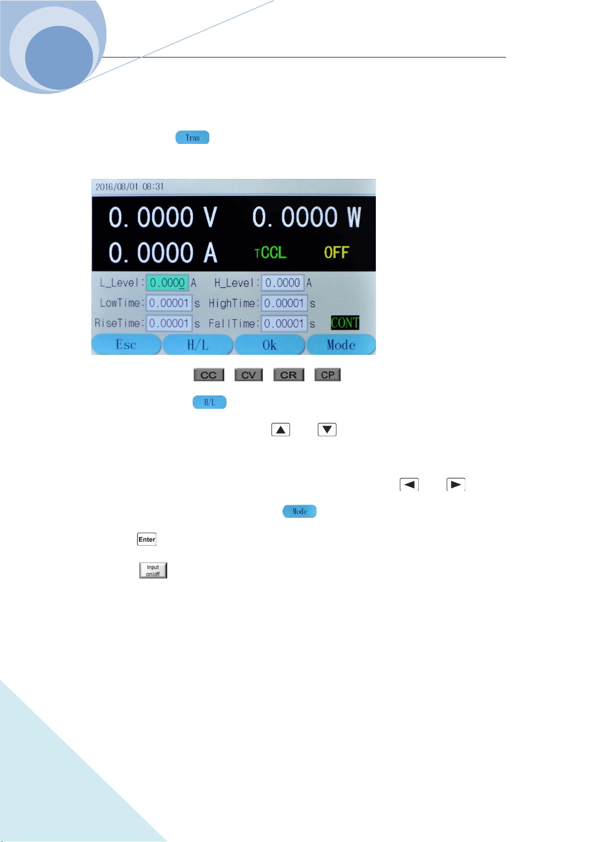
Chapter IV Local Operation
73
ARRAY
4.7 Transient Operation
The operation procedures for transient operation are shown as below:
1. Press dynamic key to enter into transient mode and the parameter setting menu, as
shown in the following diagram:
2. Press function key ( , , , ) to select the basic operation mode
and press dynamic key to confirm the high or low of the function.
3. Switch to parameter setting menu via and keys;
4. Enter the transient low level, the transient high level, the low level time, the high time, the
rising time, the falling time by the number keypad, or via knob with and keys;
5. Set the Mode level via knob or dynamic keys;
6. Press key to confirm;
7. Press key to open the load.
8. If it is in pulsed transient operation or the toggled transient operation, one trigger occurs when
the signal at the trigger terminal (TRIGIN)is low level.
4.7.1 Continuous Transient Operation
Example : Take 3751A as an example, set the voltage level periodically switch between 10V and
150V, the time for rising edge to 10ms, the high level time to 200ms, the time for falling edge to
20ms and the low level time to 400ms. The load is in continuous transient operation. The
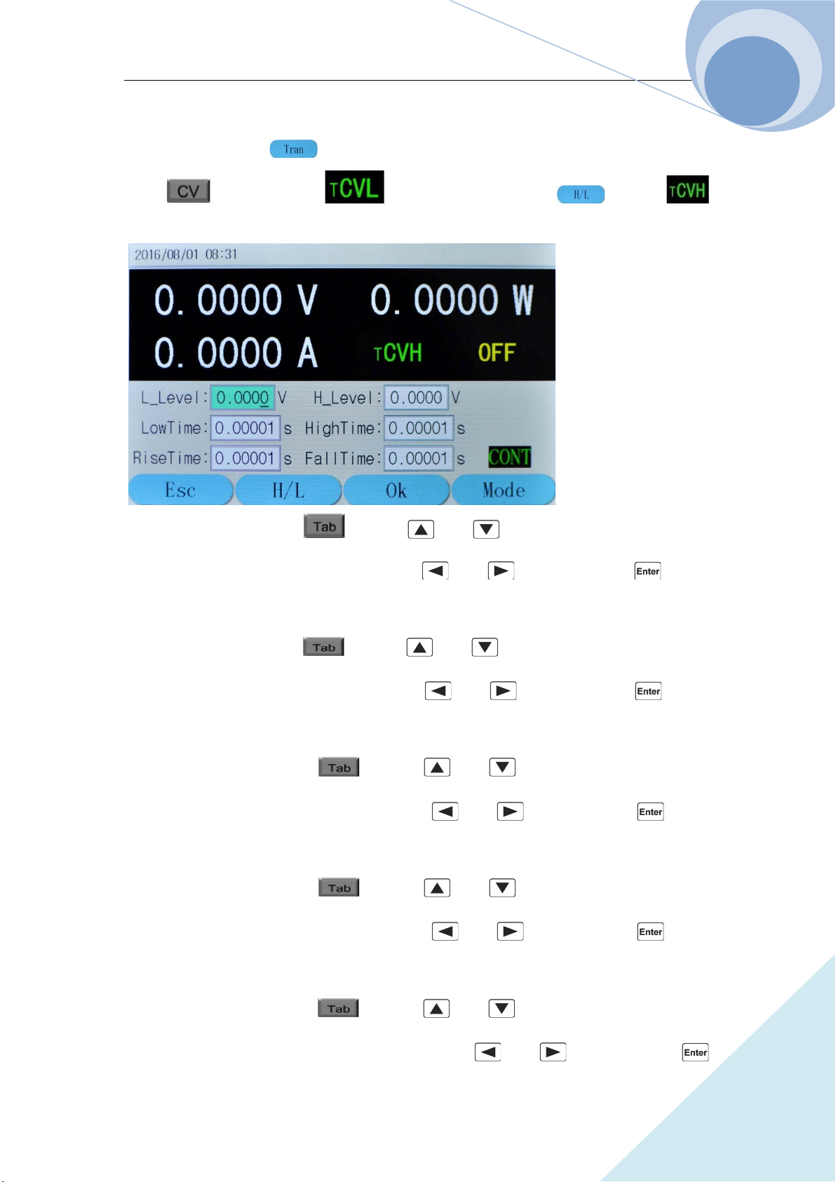
Chapter IV Local Operation
74
ARRAY
procedures are shown as below:
Step 1: Press dynamic key to enter into transient mode and the parameter setting menu;
press key to enter into mode; then press dynamic key to
mode; as in the following diagram:
Step 2: Select “L_Level” via key or and keys; enter the transient low level
10 by the number keypad, or via knob with and keys; then press key to
confirm;
Step 3: Select “H_Level” via key or and keys; enter the transient high level
150 by the number keypad, or via knob with and keys; then press key to
confirm;
Step 4: Select “LowTime” via key or and keys; enter the low level time
0.40000 by the number keypad, or via knob with and keys; then press key to
confirm;
Step 5: Select “LowTime” via key or and keys; enter the low level time
0.40000 by the number keypad, or via knob with and keys; then press key to
confirm;
Step 6: Select “RiseTime” via key or and keys; enter the time for rising
edge 0.01000 by the number keypad, or via knob with and keys; then press
Chapter IV Local Operation
75
ARRAY
key to confirm;
Step 7: Select “FallTime” via key or and keys; enter the time for falling
edge 0.02000 by the number keypad, or via knob with and keys; then press
key to confirm;
Step 8: Select “Mode” via key or and keys; select Cont via knob or
dynamic keys; then press key to confirm;
Step 9: Press key to open the load.
The corresponding SCPI commands of the above procedures should be as follows:
MODE CVH ; Set the mode
SYST:STAT TRAN ; Enter into transient mode
VOLT 10 ; Set the transient low level
VOLT: TLEVel 150 ; Set the transient high level
TRAN:LTIME 400ms ; Set the low level time
TRAN:HTIME 200ms ; Set the high level time
TRAN:RTIME 10ms ; Set the time for rising edge
TRAN:FTIMR 20ms ; Set the time for falling edge
TRAN:MODE CONT ; Select transient operation mode
INP ON ; Open the mode
4.7.2 Pulsed Transient Operation
Example : If the load is in external trigger mode, set the voltage level periodically switch between
1A and 5A, the time for rising edge to 10us, the high level time to 1ms, the time for falling edge to
10us and the low level time to 1ms. The load is in pulse transient operation and executes one
trigger simultaneously. The procedures are shown as below:
Step 1: Press dynamic key to enter into transient mode and the parameter setting menu;
press key to enter into mode;
Chapter IV Local Operation
76
ARRAY
Step 2: Select “L_Level” via key or and keys; enter the transient low level
1 by the number keypad, or via knob with and keys; then press key to
confirm;
Step 3: Select “H_Level” via key or and keys; enter the transient high level
5 by the number keypad, or via knob with and keys; then press key to
confirm;
Step 4: Select “LowTime” via key or and keys; enter the low level time
0.00100 by the number keypad, or via knob with and keys; then press key to
confirm;
Step 5: Select “HighTime” via key or and keys; enter the high level time
0.00100 by the number keypad, or via knob with and keys; then press key to
confirm;
Step 6: Select “RiseTime” via key or and keys; enter the time for rising
edge 0.00001 by the number keypad, or via knob with and keys; then press
key to confirm;
Step 7: Select “FallTime” via key or and keys; enter the time for falling
edge 0.00001 by the number keypad, or via knob with and keys; then press
key to confirm;
Step 8: Select “Mode” via key or and keys; select Pulse via knob or
dynamic keys; then press key to confirm;
Step 9: Press key to open the load;
Step 10: Send the load the trigger initial command: INIT or INIT:CONT;
Step 11: The signal at the trigger terminal (TRIG IN) is low and the load executes one trigger.
The corresponding SCPI commands of the above procedures should be as follows:
Chapter IV Local Operation
77
ARRAY
MODE CCL ; Set the mode
SYST:STAT TRAN ; Enter into transient mode
CURR 1 ; Set the transient low level
CURR: TLEVel 5 ; Set the transient high level
TRAN:LTIME 1ms ; Set the low level time
TRAN:HTIME 1ms ; Set the high level time
TRAN:RTIME 10us ; Set the time for rising edge
TRAN:FTIMR 10us ; Set the time for falling edge
TRAN:MODE PULS ; Select transient operation mode
INP ON ; Open the load
INIT ;Trigger initialization
TRIG ; Execute one pulse operation
4.7.3 Toggle Transient Operation
Example : If the load is in external trigger mode, set the resistance level periodically switch
between 200Ω and 500Ω, the time for rising edge to 10ms, the high level time to 200ms, the time
for falling edge to 10ms and the low level time to 100ms. The load is in toggle transient operation
and executes one trigger simultaneously. The procedures are shown as below:
Step 1: Press dynamic key to enter into transient mode and the parameter setting menu;
press key to enter into mode; then press dynamic key to
mode;
Step 2: Select “L_Level” via key or and keys; enter the transient low level
0.2 by the number keypad, or via knob with and keys; then press key to
confirm;
Step 3: Select “H_Level” via key or and keys; enter the transient high level
0.5 by the number keypad, or via knob with and keys; then press key to
confirm;
Chapter IV Local Operation
78
ARRAY
Step 4: Select “LowTime” via key or and keys; enter the low level time
0.10000 by the number keypad, or via knob with and keys; then press key to
confirm;
Step 5: Select “LowTime” via key or and keys; enter the low level time
0.10000 by the number keypad, or via knob with and keys; then press key to
confirm;
Step 6: Select “RiseTime” via key or and keys; enter the time for rising
edge 0.01000 by the number keypad, or via knob with and keys; then press
key to confirm;
Step 7: Select “FallTime” via key or and keys; enter the time for falling
edge 0.01000 by the number keypad, or via knob with and keys; then press
key to confirm;
Step 8: Select “Mode” via key or and keys; select Togg via knob or
dynamic keys; then press key to confirm;
Step 9: Press key to open the load;
Step 10: Send the load the trigger initial command: INIT or INIT:CONT;
Step 11: The signal at the trigger terminal (TRIG IN) is low and the load executes one trigger.
The corresponding SCPI commands of the above procedures should be as follows:
MODE CRL ;Set the mode
SYST:STAT TRAN ;Enter the transient operation
RES 200 ;Set the transient low level
RES: TLEV 500 ;Set the transient high level
TRAN:LTIME 200ms ; Set the low level time
TRAN:HTIME 200ms ; Set the high level time
TRAN:RTIME 1ms ; Set the time for rising edge
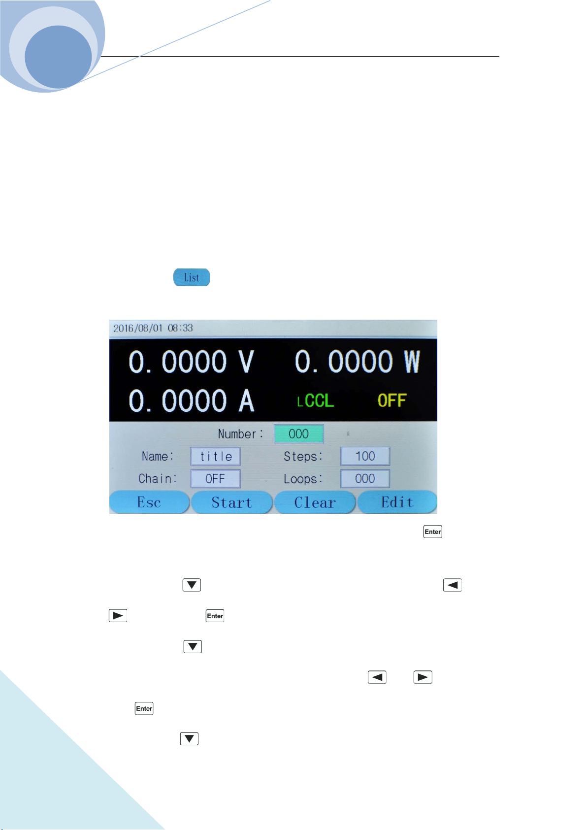
Chapter IV Local Operation
79
ARRAY
TRAN:FTIMR 1ms ; Set the time for falling edge
TRAN:MODE TOGG ; Select the transient operation mode
INP ON ; Open the load
INIT ;Trigger initialization
TRIG ;Execute one toggle operation
4.8 List Operation
The operation procedures for list operation are shown as below:
1. Press dynamic key to enter into list operation mode and the parameter setting menu,
as shown in the following diagram:
2. Select the “Number” via the number keypad or via the knob and then press key to
confirm;
3. Select Name via key and set the name ((5 characters) via the knob or the and
keys; then press key to confirm;
4. Select Chain via key and select the sequence number or whether or not link (ON
means chained, OFF means non-chained.) via the knob or the and keys; then
press key to confirm;
5. Select Steps via key and select the sequence number or whether or not link (ON means
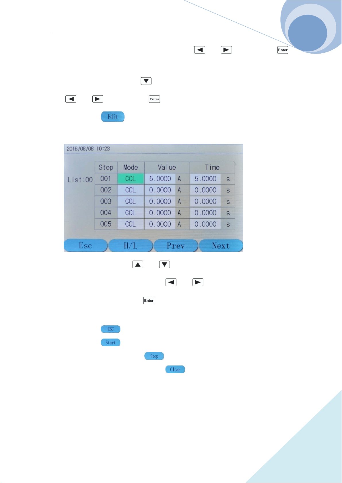
Chapter IV Local Operation
80
ARRAY
linking, OFF means non-linking.) via the knob or the and keys; then press
key to confirm; Select the chained sequence number or whether or not chained
6. Select Step QTY function via key and enter the set step number via the knob or the
and keys; then press key to confirm;
7. Press dynamic key to enter into function edition menu, as shown in the following
diagram:
8. Select the step number via and keys; then select the editing parameter via
TAB key; then make the selection via the and key or the knob and enter the
value via the keypad; then press key to confirm and save the data into the designed
EEPROM;
9. Press dynamic key to return to the list operation menu;
10. Press dynamic key to start the list operation program;
11. At starting status, press dynamic key to stop the list operation program;
12. In the list operation menu, press dynamic key, system will eliminate the program at
current number
4.8.1 List Editing
Example : Edit a new sequence. The sequence number is 0; the sequence name is Test0. The
sequence steps: Step 1: CCL, 1A, 1S; Step 2: CCH, 10V, 1S; Step 3: CVH, 10V, 1S; Step 4: CRL,
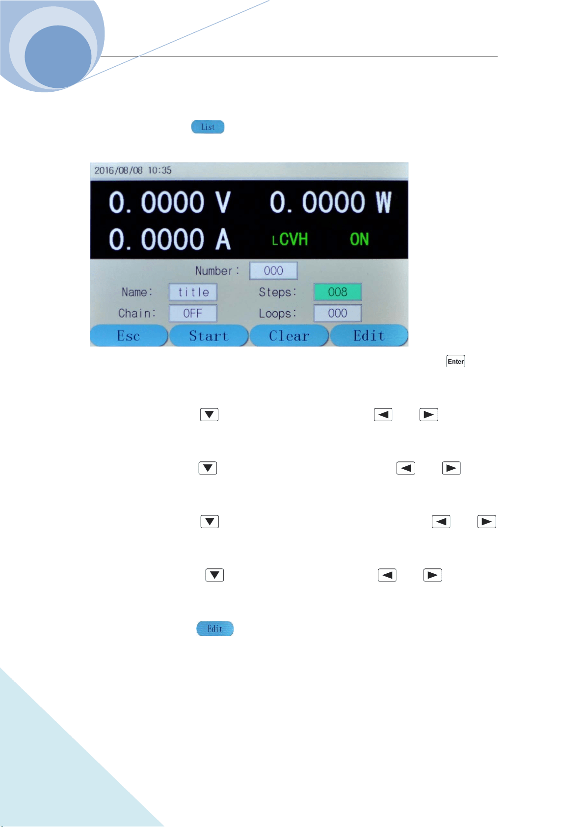
Chapter IV Local Operation
81
ARRAY
1Ω, 1S; Step 5: CP, 200W, 1S. The cycle times is 10; disable the sequence chain; start the
sequence operation; stop the sequence operation. The operation procedures are as below:
Step 1: Press dynamic key to enter into list operation mode and the parameter setting
menu at initial interface, as shown in the following diagram:
Step 2: Set the sequence Number to 0 via the keypad or via the knob and then press key to
confirm;
Step 3: Select Name via key and set the name to Test0 via and keys and the
knob;
Step 4: Select Chain via key and edit the chain option to OFF via and keys or
the knob;
Step 5: Select Steps via key and edit the step quantity number to 5 via and
keys or the knob;
Step 6: Select Loops via key and edit the value to 10 via and keys or the
knob;
Step 7: Press dynamic key to enter into function edition menu, as shown in the
following diagram:
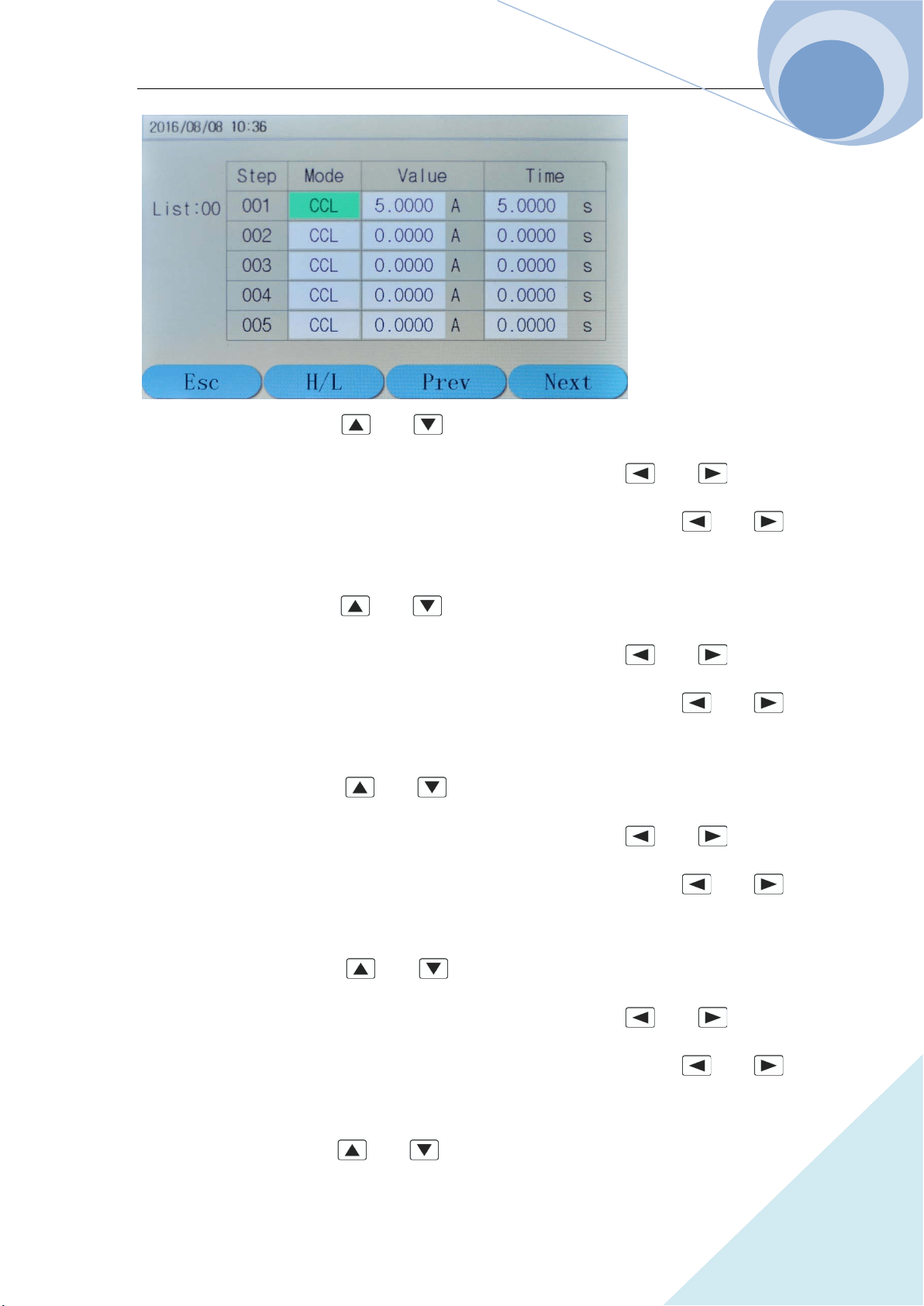
Chapter IV Local Operation
82
ARRAY
Step 8: Select Step 001 via and keys; select Mode and set mode to CCL via the
knob; then select Value option via TAB key; set the value to 1.0000 via and keys or
via the knob; then select Time option via TAB key; set the value to 1.000 via and
keys or via the knob;
Step 9: Select Step 002 via and keys; select Mode and set mode to CCH via the
knob; then select Value option via TAB key; set the value to 20.000 via and keys or
via the knob; then select Time option via TAB key; set the value to 1.0000 via and
keys or via the knob;
Step 10: Select Step 003 via and keys; select Mode and set mode to CVH via the
knob; then select Value option via TAB key; set the value to 10.000 via and keys or
via the knob; then select Time option via TAB key; set the value to 1.0000 via and
keys or via the knob;
Step 11: Select Step 004 via and keys; select Mode and set mode to CRL via the
knob; then select Value option via TAB key; set the value to 1.0000 via and keys or
via the knob; then select Time option via TAB key; set the value to 1.0000 via and
keys or via the knob;
Step 12: Select Step 005 via and keys; select Mode and set mode to CP via the knob;

Chapter IV Local Operation
83
ARRAY
then select Value option via TAB key; set the value to 200.00 via and keys or via the
knob; then select Time option via TAB key; set the value to 1.0000 via and keys or
via the knob;
Step 13: Press dynamic key to return to the list operation menu;
Step 14: Press dynamic key to start the current list operation program and it will stop
automatically when the operation is finished;
Step 15: During the list operation, press dynamic key to stop the ruing list operation.
The corresponding SCPI commands of the above procedures should be as follows:
LIST:NUMB 0 ;Call the sequence numbered 0
LIST:MEMO “Test0” ;Name the sequence Test.
LIST:EDIT 0, CCL,1A,1S
LIST:EDIT 1, CCH,20A,1S
LIST:EDIT 2, CVH,10V,1S
LIST:EDIT 3, CRL,1R,1S
LIST:EDIT 4, CP,200W,1S ;The above five commands are the sequence steps
LIST:COUN 10 ;Cyclic time
LIST:CHA OFF ;Close the chained sequence of the list
LIST ON ;Start the list operation
LIST OFF ;Stop the list operation
4.8.2 Starting/Stopping the List
Example: Start the No. 0 sequence and stop the active list operation.
Step 1: Press dynamic key to enter into list operation mode at initial interface;
Step 2: Set the NO to 0 via the keypad or via the knob and press key to confirm (The recall
number should be the sequence number in EEPROM.);
Step 3: Press dynamic key to start the current list operation
Step 4: Press dynamic key to stop the list operation;
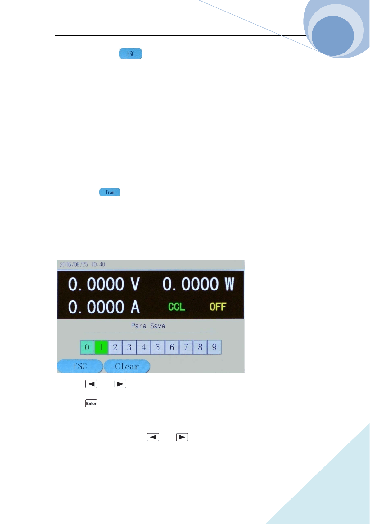
Chapter IV Local Operation
84
ARRAY
Step 5: Press dynamic key to return to the initial operation menu.
The corresponding SCPI commands of the above procedures should be as follows:
LIST: NUMB 0 ;Call the sequence numbered 0
LIST ON ;Start the list operation
LIST OFF ;Stop the list operation
4.9 Saving and Recalling
The operation procedures for transient operation are shown as below:
Press dynamic key to enter into transient mode and the parameter setting menu, as
shown in the following diagram:
The saving and recalling operation procedures are as followings:
1. Press SAVE key to enter into the saving menu as in the following diagram; or press CALL
key to enter into the recalling menu of the load:
2. Press and keys or the knob to select the saving or recalling location;
3. Press key to confirm. The parameters will be saved into the EEPROM. If the pointed
location has saved value in the EEPROM, the location will be green as in the above diagram;
4. Select the saved location via and keys or via the knob and press dynamic Clear
key to eliminate the value of the location, then the location will not be green any more.

Chapter IV Local Operation
85
ARRAY
Example 1: Set the load to CCL mode; set the current be 2A. Open the load; save the parameters
of the status to location 0 in the EEPROM; open the load and upload automatically:
Step 1: Set the load CCL mode and the current 2A, then open the load (For details, please refer to
4.5.1.);
Step 2: Press SAVE key to enter into the saving interface of the load;
Step 3: Select the saved Location 0 via and keys or the knob;
Step 4: Press key to confirm the saving, and then press dynamic key to exit the
saving menu of the load.
The corresponding SCPI commands of the above procedures should be as follows:
MODE CCH ;Set the load CCH mode
CURR 2 ;Set the current level 2A
INP ON ;Open the load
*SAV 0 ;Save the parameters to Location 0 in the EEPROM
Example 2: Based on the above example, set the load CV mode; set the voltage be 40V. Turn off
the load. Recall the values saved in Location 0 in EEPROM. And the detailed operation
procedures are as below:
Step 1: Set the load CV mode and the voltage 40V, then turn off the load (For details, please refer
to 4.5.2.);
Step 2: Press CALL key to enter into the recalling interface of the load;
Step 3: Select the recalling location: Location 0 via and keys or the knob;
Step 4: Press key to confirm the saving, and then press dynamic key to exit the
recalling menu of the load.
The corresponding SCPI commands of the above procedures should be as follows:
MODE CV ;Set the load CV mode
VOLT 40 ;Set the voltage level 40V
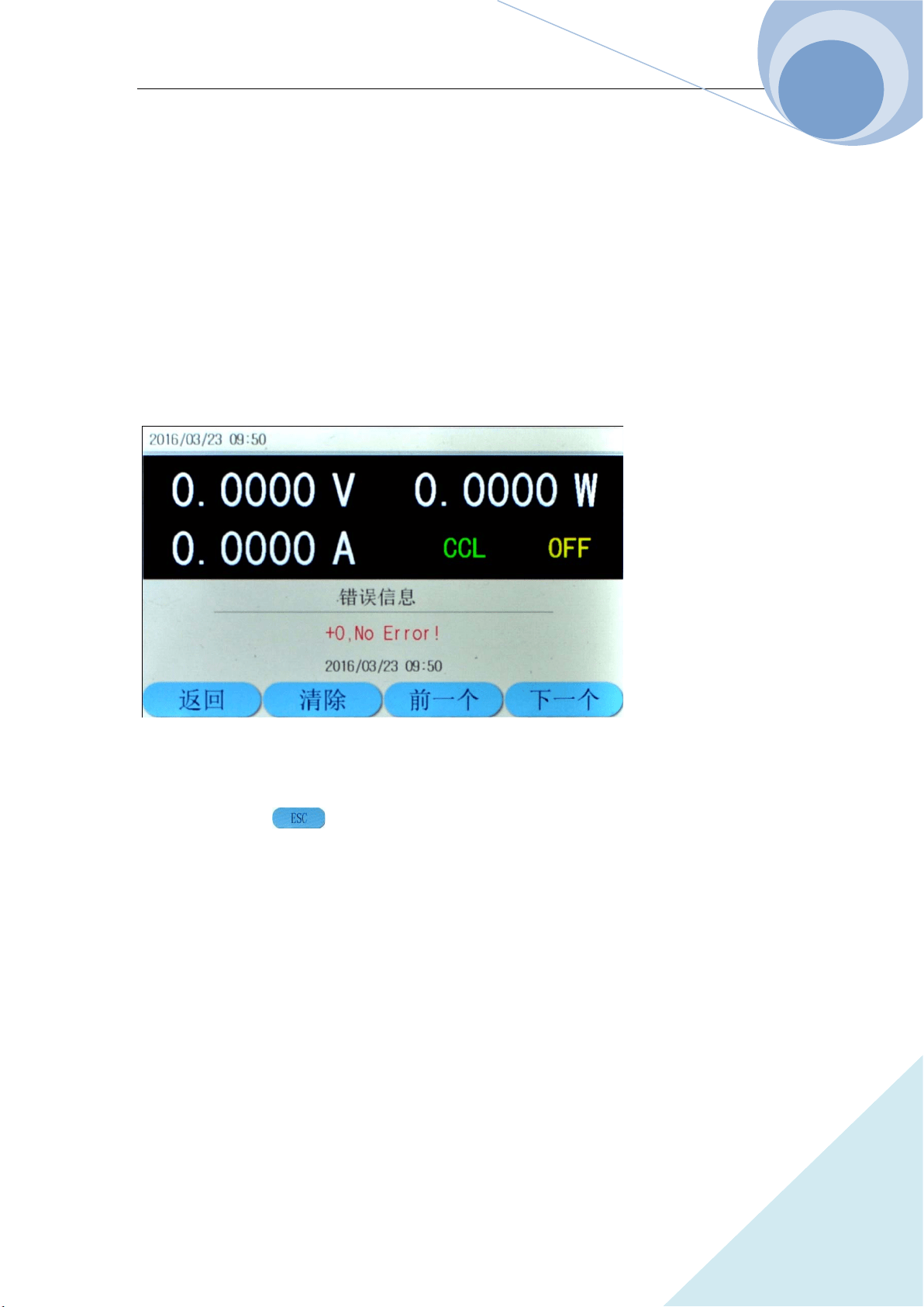
Chapter IV Local Operation
86
ARRAY
INP OFF ;Turn off the load
*RCL 0 ;Recall the values in Location 0 in EEPROM
4.10 Checking and Clearing Protection Setting
The operation procedures for checking and clearing protection setting are shown as below:
1. Eliminate the reasons for the protection of electronic load first;
2. Press Error key to enter into error message displaying interface, as shown in the following
diagram:
3. The error message displaying interface will display the error that occurred after the last time
the system had introduced.
4. Press dynamic key to return to the system initial interface;
5. If the errors have been ruled out, the system will no longer display the next time you enter the
error interface.
.
Example : Clear RV protection of the load. The detailed procedures are as below:
Step 1: Correctly re-connect the power supply and the electronic load;
Step 2: Press ERROR key to enter the error messages interface and check the occurred error;
Step 3: Press dynamic EXIT key to exit the error messages interface.
The corresponding SCPI commands of the above procedures should be as follows:
SYST:ERR? ;Check the error code and information

Chapter IV Local Operation
87
ARRAY
INP:PROT:CLE ;Clear the protection status
4.11 Trigger Operation
When the trigger mode is external mode (EXTernal), the operation procedures for trigger
operation are shown as below:
1. Set the trigger function (Refer to 2.8 for details.);
2. The trigger terminal (TRIGIN) receives a TTL falling edge signal, and a trigger occurs.
Example 1: Select “List” for the trigger function to trigger a sequence operation. The sequence is
the one mentioned in Example 1 in 4.8.1. The detailed procedures are as below:
Procedures Detailed Operation
Step 1
Select “List” in main menu for the trigger function(Please refer to
4.14.6 for details.);
Step 2 Send initial command INT or INIT:CONT;
Step 3
Trigger terminal (TRIG IN) receives the TTL falling edge. The load’s
input will change according to the sequence parameters.
The corresponding SCPI commands of the above procedures should be as follows:
TRIG:FUNC LIST ;Select LIST for the trigger function
INIT ;Trigger initialization
TRIG ;A trigger occurs
4.12 Main Menu of the Eload
The operation procedures for the main menu are shown as below:
1. Press dynamic key to enter the main menu as the following diagram:
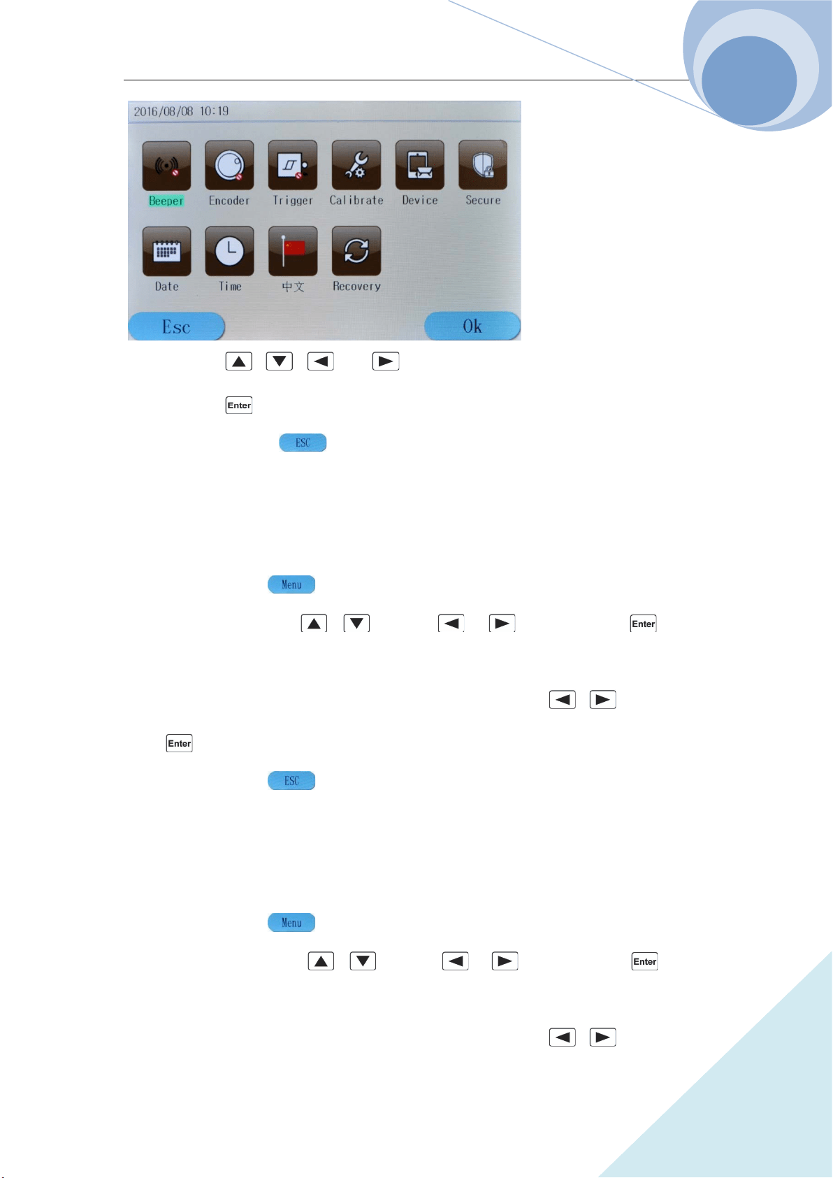
Chapter IV Local Operation
88
ARRAY
2. Press , , and keys to select the menu item;
3. Press key to confirm;
4. Press dynamic key to exit the main menu.
4.12.1 Buzzer
Example: Buzzer disabled. The detailed procedures are as below:
Step 1: Press dynamic key to enter into the main menu;
Step 2: Select Buzzer via , keys or , keys and press key to
confirm;
Step 3: The following diagram will be displayed. Select Disabled via , keys and then
press key to confirm;
Step 4: Press dynamic key to exit the main menu.
4.12.2 Encoder
Example: Encoder disabled. The detailed procedures are as below:
Step 1: Press dynamic key to enter into the main menu;
Step 2: Select Encoder via , keys or , keys and press key to
confirm;
Step 3: The following diagram will be displayed. Select Disabled via , keys and then
Chapter IV Local Operation
89
ARRAY
press key to confirm;
Step 4: Press dynamic key to exit the main menu.
4.12.3 Trigger
Example: Encoder disabled. The detailed procedures are as below:
Step 1: Press dynamic key to enter into the main menu;
Step 2: Select Trigger via , keys or , keys and press key to confirm;
Step 3: The following diagram will be displayed. Select Disabled via , keys and then
press key to confirm;
Step 4: Press dynamic key to exit the main menu.
4.14.6 Calibration
Refer to <<375XA Calibration Manual>> for details.
4.12.5 Information
Example: Check device information. The detailed procedures are as below:
Step 1: Press dynamic key to enter into the main menu;
Step 2: Select Device via , keys or , keys and press key to
confirm;
Step 3: The following diagram will be displayed;
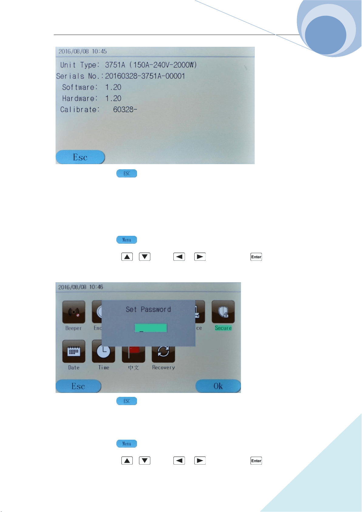
Chapter IV Local Operation
90
ARRAY
Step 4: Press dynamic key to exit the main menu.
4.12.6 Safety Code
Change the safety code. The detailed procedures are as below:
Step 1: Press dynamic key to enter into the main menu;
Step 2: Select Secure via , keys or , keys and press key to confirm;
Step 3: The following diagram will be displayed;
Step 4: Press dynamic key to exit the main menu.
Example 1: Change the safety code to 123456. The detailed procedures are as below:
Step 1: Press dynamic key to enter into the main menu;
Step 2: Select Secure via , keys or , keys and press key to confirm;
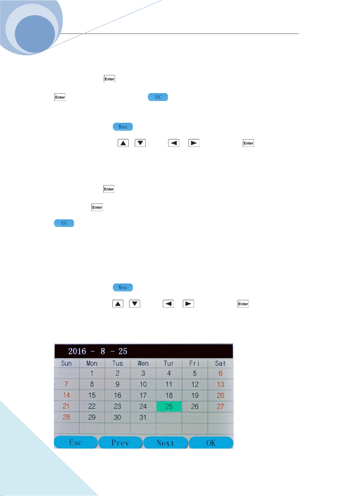
Chapter IV Local Operation
91
ARRAY
Step 3: The above diagram will be displayed;
Step 4: Enter the system safety code: 003751 (the factory default safety code)via the number
keypad, then press key to confirm. Step 5: Enter 123456 via the number keypad and press
key to confirm. Press dynamic key to exit the main menu.
Example 2: Cancel the safety code. The detailed procedures are as below:
Step 1: Press dynamic key to enter into the main menu;
Step 2: Select Secure via , keys or , keys and press key to confirm;
Step 3: The above diagram will be displayed.
Step 4: Enter the system safety code: 003751 (the factory default safety code)via the number
keypad, then press key to confirm.
Step 5: Press key to confirm directly without entering any character. Then press dynamic
key to exit the main menu.
4.12.7 Date
Example: Check date information. The detailed procedures are as below:
Step 1: Press dynamic key to enter into the main menu;
Step 2: Select Date via , keys or , keys and press key to confirm;
Step 3: The following diagram will be displayed;
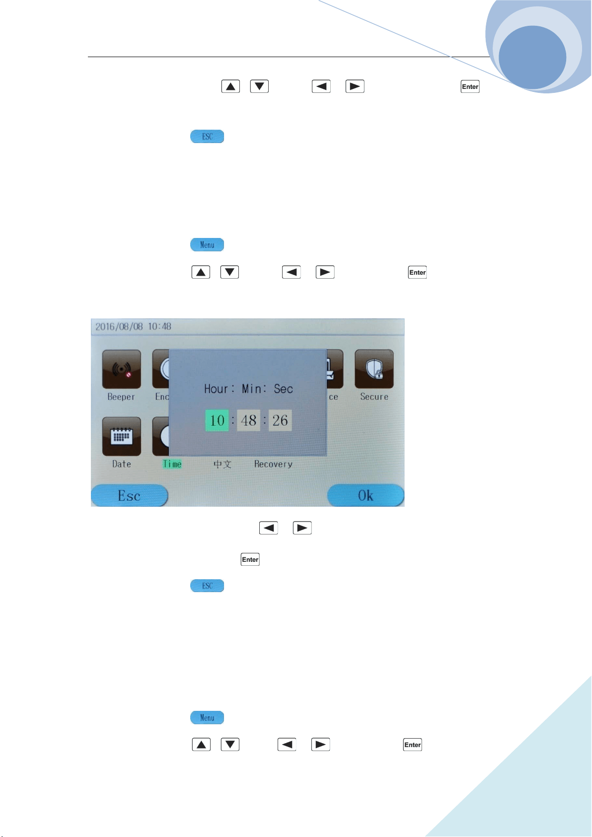
Chapter IV Local Operation
92
ARRAY
Step 4: Select the set date via , keys or , keys. After pressing key,
the initial interface will display the set date;
Step 5: Press dynamic key to exit the main menu.
4.12.8 Time
Example: Check time information. The detailed procedures are as below:
Step 1: Press dynamic key to enter into the main menu;
Step 2: Select Time via , keys or , keys and press key to confirm;
Step 3: The following diagram will be displayed;
Step 4: Select Hour, Min and Sec via , keys and regulate the level via the number
keypad or the knob. After pressing key, the initial interface will display the set time;
Step 5: Press dynamic key to exit the main menu.
4.12.9 Language
The language of the system can be switched between English and Chinese. The detailed
procedures are as below:
Step 1: Press dynamic key to enter into the main menu;
Step 2: Select 中文 via , keys or , keys and press key to confirm;
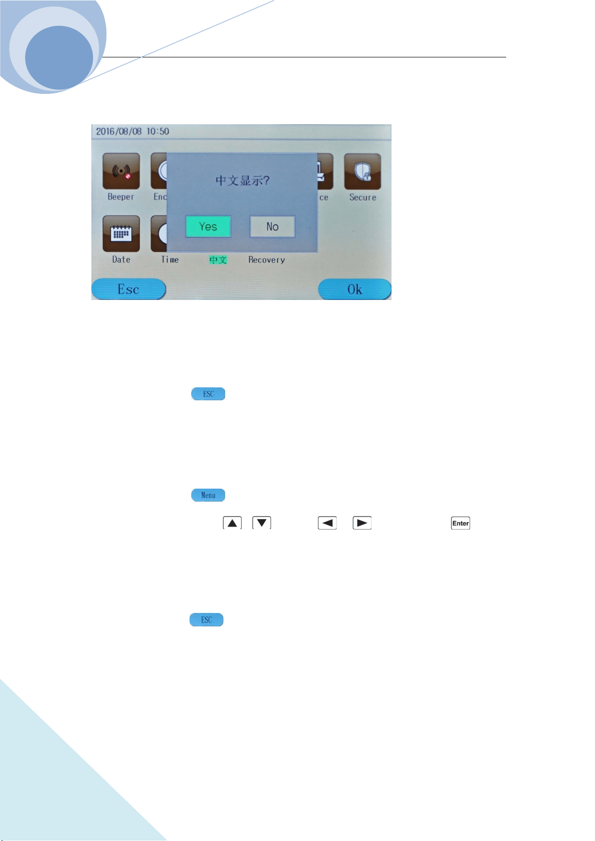
Chapter IV Local Operation
93
ARRAY
Step 3: The following diagram will be displayed;
Step 4: If Yes is chosen, the language will be switched; if No is not chosen, the language will not
be switched;
Step 5: Press dynamic key to exit the main menu.
4.12.10 System Default
This menu will help to restore the factory default settings. The detailed procedures are as below:
Step 1: Press dynamic key to enter into the main menu;
Step 2: Select Recovery via , keys or , keys and press key to
confirm;
Step 3: In the pop-up dialog, If Yes is chosen, it will restore the factory default settings; if No is
not chosen, it will not restore the factory default settings;
Step 4: Press dynamic key to exit the main menu.
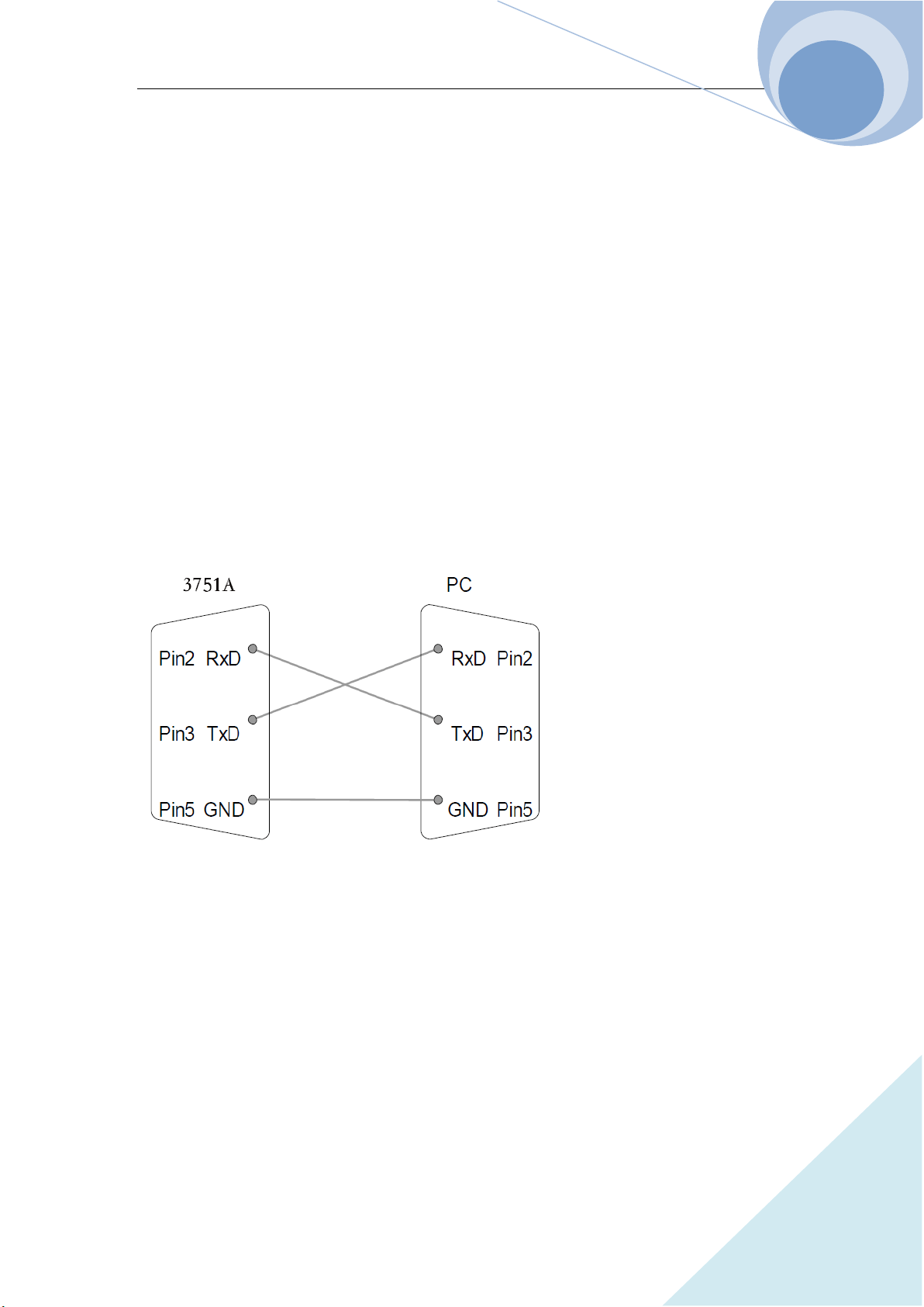
Chapter V Remote Programming Operation
94
ARRAY
Chapter V Remote Programming Operation
The load supports both local operation and remote control. Previous chapters have introduced in
details how to operate the load via the front panel keys and the knob. This chapter will introduce
how to remote program the load via the remote interfaces. The similarities between the local
operation and the remote programming will become apparent as your reading this chapter.
First of all this chapter will help you quickly be familiar with the remote programming. The
examples are the simplest SCPI commands. For more detailed explanations, please refer to
《ARRAY 375XA Electronic Load SCPI Programming Guide》.
5.1 Communication Interface
5.1.1 RS232
RS232 interface is the standard configuration of the load. Correctly connect the load and the PC
via the RS232 interface shipped with the load. Select RS232 interface in the MENU, and set the
Baud rate, parity, data bit, stop bit and so on corresponding parameters. Set the same parameters in
the PC software. Then input the SCPI commands in the PC software interface to operate the load.
5.1.2 USB
6. USB interface is the standard configuration of the load. Correctly connect the load and the
PC via the USB interface. Select USB interface in “I/Oconfig” menu. Input the SCPI
commands in the PC software interface to operate the load.
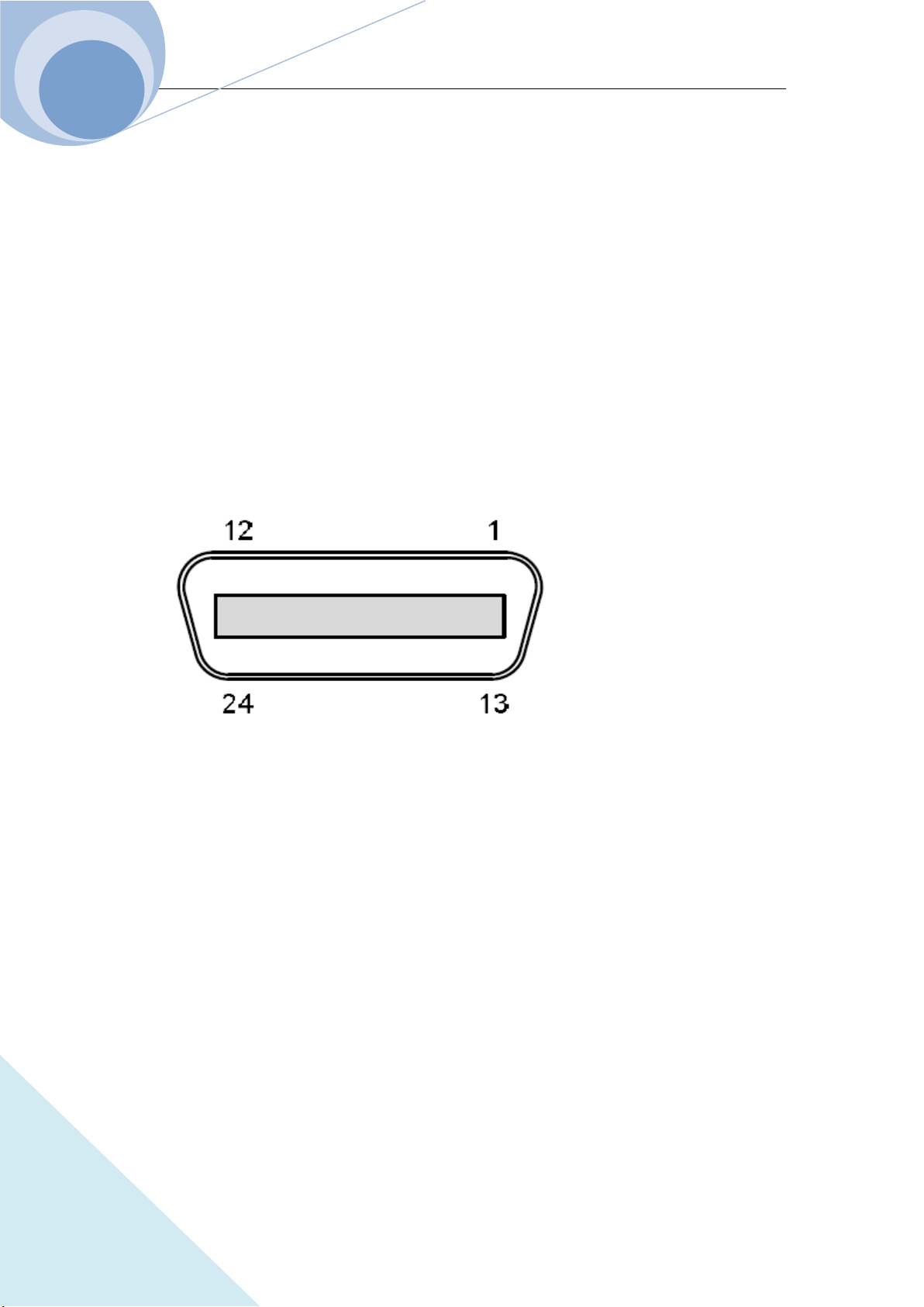
Chapter V Remote Programming Operation
95
ARRAY
5.1.3 GPIB
GPIB interface is the optional configuration of the load. Only installing the GPIB communication
module in the load and installing the corresponding GPIB communication module driver in the PC,
the function can be used. Correctly connect the load and the PC via the GPIB interface, select
GPIB interface in “I/Oconfig” menu, and set the GPIB address. Select different GPIB address in
PC software. Input the legal SCPI commands in the PC software interface to operate the load.
Notes:
GPIB address 0~30;
Maximum 15 devices altogether, 20m cable length, 2m between each device;
Unique address assigned to each device.
Pin Assignment:
Pin Signal Pin Signal
1~4 Data I/O 1~4 13~16 Data I/O 5~8
5 EOI 17 REN
6 DAV 18 Ground (DAV)
7 NRFD 19 Ground (NRFD)
8 NDAC 20 Ground (NDAC)
9 IFC 21 Ground (IFC)
10 SRQ 22 Ground (SRQ)
11 ATN 23 Ground (ATN)
12 SHIELD Ground 24 Single GND
Example 1: Select RS232 interface, set the Baud rate to 9600, parity to None, data bit to 8, stop
bit to 2 and the flow control to ON.
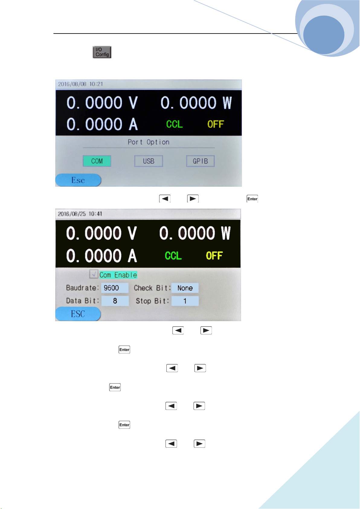
Chapter V Remote Programming Operation
96
ARRAY
Step 1: Press key to enter into the I/O configuration set menu as in the following
diagram:
Step 2: Select the COM menu item via and keys, then press key to enter;
Step 3: Select the Baud Rate menu item via and keys, set the parameter to 9600 via
the knob and then press key to enter;
Step 4: Select the Data Bit menu item via and keys, set the parameter to 8 via the
knob and then press key to enter;
Step 5: Select the Polarity menu item via and keys, set the parameter to None via
the knob and then press key to enter;
Step 6: Select the Stop Bit menu item via and keys, set the parameter to 2 via the
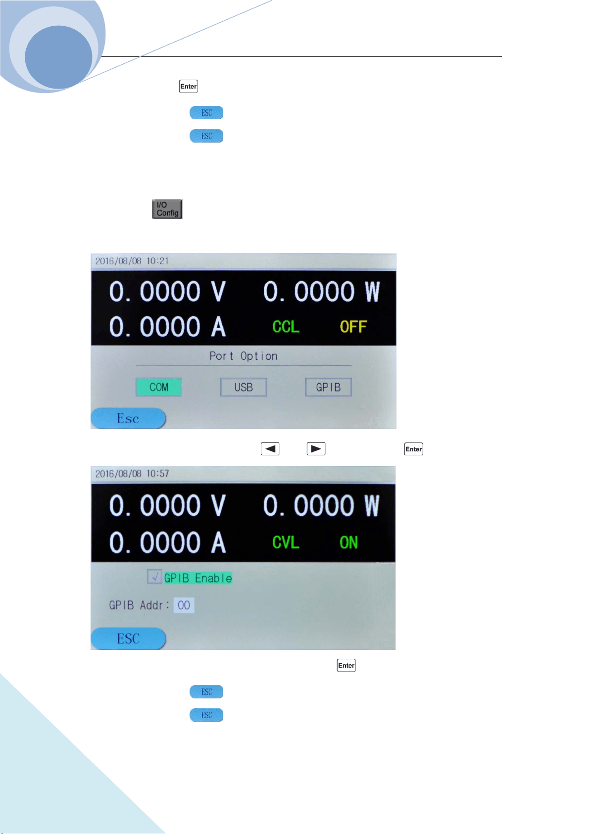
Chapter V Remote Programming Operation
97
ARRAY
knob and then press key to enter;
Step 7: Press dynamic key to exit the COM menu;
Step 8: Press dynamic key to exit the “I/OConfig” menu.
Example 2: Select GPIB communication port and set the address to 4.
Step 1: Press key to enter into the I/O configuration set menu as in the following
diagram:
Step 2: Select the GPIB menu item via and keys, then press key to enter;
Step 3: Set the parameter to 4 via the knob and then press key to enter;
Step 4: Press dynamic key to exit the GPIB menu;
Step 5: Press dynamic key to exit the I/OConfig menu.

Chapter V Remote Programming Operation
98
ARRAY
5.2 Remote Programming Display
When the load receives the remote command: SYSTem: REMote via RS232, USB or GPIB, the
remote status at the upper right corner will be displayed and the load will be in remote
control status. In remote control status, all the operations of the keys on the front keypad and the
knob (except key) are invalid. All the operation of the load is controlled by the remote
controller. When the load receives the local control command: SYSTem: LOCal, the remote status
at the upper right corner will not be displayed and the load will return to local control
status. In remote control status, the load will return to local control status when being pressed
key.
5.3 Sending Remote Setting Commands
As local operation on the device, users can remotely set the operation mode and operation
parameters of the device for the load from the computer.
5.4 Returning Data
The load can return not only the parameters such as parameter setting level, input voltage level,
input current level, input power level and so on but also the internal information and the device
identification to the computer. For example, the query command “MEASure: CURRent?” is to ask
the load to return the actual current at the input terminal. Please refer to 《Array 375XA Electronic
Load SCPI Programming Guide》 for detailed information on the query commands. The load
stores and holds the response information to the query command in the output buffer until it is
read by the computer or replaced by new information.
5.5 Remote Programming Commands
The SCPI commands have many optional key words for the programmer. Being familiar with
those key words will help to know the programming better. Most of the commands have a query
syntax which will return the present parameter setting value to the controller. Please refer to

Chapter V Remote Programming Operation
99
ARRAY
《Array 375XA Electronic Load SCPI Programming Guide》 for detailed information. The main
functions of the load can be remotely programmed by some relative commands. Then following
points are important when remotely programming the current level, the resistance level, the
voltage level and the power level.
5.5.1 Basic Test Mode
No matter the associated basic mode is active or not, the current level, the resistance level, the
voltage level and the power level can be remotely programmed. If the input is turned on and the
associated mode is selected, the corresponding programmed value will take effect at the input
terminal.
5.5.2 Transient Level
The transient high level of CC, CV or CR mode must higher that the respective low level, or the
transient operation will be disabled.
5.5.3 Programmable Current Protection
When the programmable current protection is enable, and the programmed current limit and time
delay are exceeded, the load’s input will be turned off automatically.
5.6 CC Mode Example
Example: Set the current level to 0.5A, and then read back the actual current level.
1 "INP OFF" ;Turn off the load’s input
2 "MODE CCL" ;Select the CCL Mode
3 "CURR 0.5" ;Set the current level to 0.5A
4 "INP ON" ;Turn on the load’s input
5 "MEAS:CURR?" ;Measure the actual input current

Chapter V Remote Programming Operation
100
ARRAY
5.7 CV Mode Example
Example: Preset the trigger voltage to 5V, and then select the external trigger source.
l "INP OFF" ;Turn off the load’s input
2 "MODE CV" ;Select the CV Mode
3 "VOLT:TRIG 5" ;Preset the trigger voltage to 5V
4 "TRIG:SOUR EXT" ;Select the external input as the trigger source
5"INP ON" ;Turn on the load’s input
In this example, when the external trigger signal is received, the input voltage will be set to 5V.
5.8 CR Mode Example
Example: Set the current protection limit to 10A, the time delay to 10s, the resistance level to
10Ω and return back the computed power level.
l. "INP OFF" ;Turn off the load’s input
2. "MODE CRL" ;Select the CRL Mode
3. "CURR:PROT 10" ;Set the current protection level to 10A
4. "CURR:PROT:DEL 10" ;Set the current protection delay time to 10s
5. "CURR:PROT:STAT ON" ;Active the current protection
6. "RES 10" ;Set the resistance level to 10Ω
7. "INP ON" ;Turn on the load’s input
8. "MEAS:POW?" ;Measure the input power level
5.9 Continuous Transient Operation Example
Example: Set the voltage transient high level, voltage transient low level, time for transient rising
edge, time for transient falling edge, high level time, low level time and parameters for transient
operations.
1 "INP OFF" ;Turn off the load’s input
2 "MODE CVL" ;Select the CVL Mode
3 "SYST:STAT TRAN" ;Open the transient

Chapter V Remote Programming Operation
101
ARRAY
4 " VOLT 0.5" ;Set the voltage transient low level to 0.5V
5 " VOLT: TLEV 1" ;Set the voltage transient high level to 1V
6 "TRAN:LTIM 200us" ;Set transient low level time to 200us
7 "TRAN:HTIM 300us" ;Set transient high level time to 300us
8 "TRAN:RTIM 10us" ;Set the time for transient rising edge to 10us
9 "TRAN:FTIM 20us" ;Set the time for transient falling edge to 20us
10 "TRAN:MODE CONT " ;Select the continuous transient operation
11 "INP ON" ;Turn on the load’s input
5.10 Pulsed Transient Operation Example
Example: Set the CV pulsed transient operation mode, select the BUS as the trigger source, and
set a high-level pulse with 1ms width.
1 "INP OFF" ;Turn off the load’s input
2 "MODE CVL" ;Select the CVL Mode
3 "SYST:STAT TRAN" ;Open the transient operation function
4 "TRIG:SOUR BUS" ;Select BUS as the trigger source
5 " VOLT 0.5" ;Set the transient low level to 0.5V
6 " VOLT: TLEV 1" ;Set the transient high level to 1V
7 "TRAN:HTIM 1ms" ;Set the transient high level time to 1ms
8 "TRAN:RTIM 10us" ;Se the time for rising edge to 10us
9 "TRAN:FTIM 10us" ;Se t the time for falling edge to 10us
10 "TRAN:MODE PULSE " ;Select PULSE as the transient operation mode
11 "INP ON ;Turn on the load’s input
12 "INIT" ;Initialize, waiting for the pulse
13 "*TRG" ;*TRG command generates a 1ms-width high-level pulse at
the load’s input
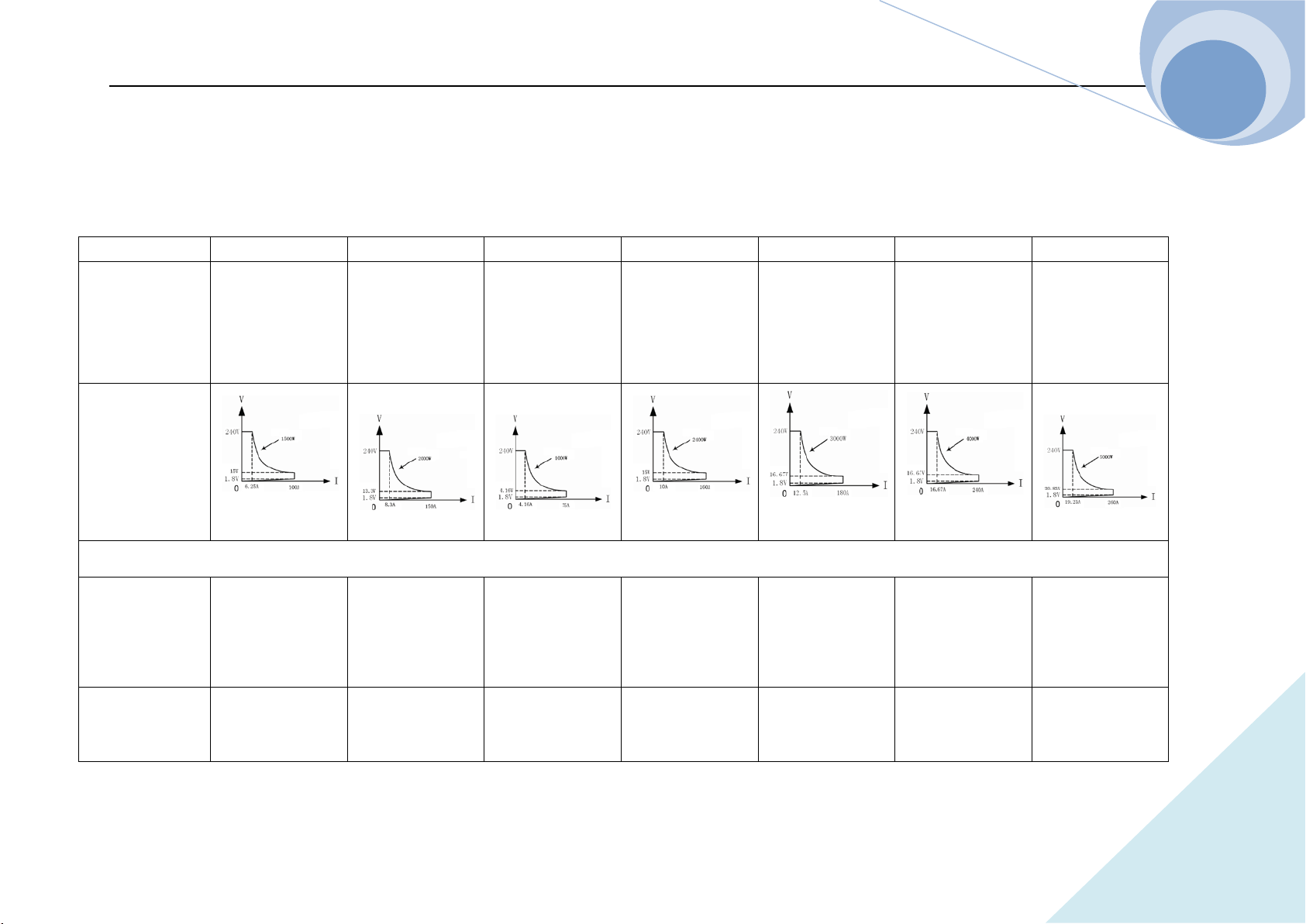
Chapter V Remote Programming Operation
102
ARRAY
Specifications
Model
3750A 3751A 3752A 3753A 3754A 3755A 3756A
Current
Voltage
Power
*1
0~100A
0~240V
1500W at 40ºC
0~150A
0~240V
2000W at 40ºC
0~75A
0~240V
1000W at 40ºC
0~160A
0~240V
2400W at 40ºC
0~180A
0~240V
3000W at 40ºC
0~240A
0~240V
4000W at 40ºC
0~260A
0~240V
5000W at 40ºC
Input
Characteristics
Constant Current Mode
Low Range
Resolution
Accuracy
0~6A
0.1mA
0.2%+5mA
0~6A
0.1mA
0.2%+5mA
0~6A
0.1mA
0.2%+5mA
0~6A
0.1mA
0.2%+5mA
0~8A
0.1mA
0.2%+5mA
0~8A
0.1mA
0.2%+5mA
0~8A
0.1mA
0.2%+5mA
High Range
Resolution
0~100A
1mA(0~100A)
0~150A
1mA(0~100A)
0~75A
1mA(0~75A)
0~160A
1mA(0~100A)
0~180A
1mA(0~100A)
0~240A
1mA(0~100A)
0~260A
1mA(0~100A)

Chapter V Remote Programming Operation
103
ARRAY
Accuracy
0.2%+10mA
10mA(100~150A)
0.2%+10mA
0.2%+10mA
10mA(100~160A)
0.2%+10mA
10mA(100~180A)
0.2%+10mA
10mA(100~240A)
0.2%+10mA
10mA(100~260A)
0.2%+10mA
Constant Voltage Mode
Range
Resolution
Accuracy
0~240V
1mV (0~100V)
10mV(100~240V)
0.2%+10mV
0~240V
1mV (0~100V)
10mV(100~240V)
0.2%+10mV
0~240V
1mV (0~100V)
10mV(100~240V)
0.2%+10mV
0~240V
1mV (0~100V)
10mV(100~240V)
0.2%+10mV
0~240V
1mV (0~100V)
10mV(100~240V)
0.2%+10mV
0~240V
1mV (0~100V)
10mV(100~240V)
0.2%+10mV
0~240V
1mV (0~100V)
10mV(100~240V)
0.2%+10mV
Constant Resistance Mode
Low Range
Resolution
Accuracy
@I>6A
0.2Ω~240K
0.1mΩ
0.5%+12mΩ
0.2Ω~240K
0.1mΩ
0.5%+12mΩ
0.2Ω~240K
0.1mΩ
0.5%+12mΩ
0.2Ω~240K
0.1mΩ
0.5%+12mΩ
0.2Ω~240K
0.1mΩ
0.5%+12mΩ
0.2Ω~240K
0.1mΩ
0.5%+12mΩ
0.2Ω~240K
0.1mΩ
0.5%+12mΩ
High Range
Resolution
Accuracy
@I<6A
0.2KΩ~2.4MΩ
0.001KΩ
0.5%+0.12KΩ
0.2KΩ~2.4MΩ
0.001KΩ
0.5%+0.12KΩ
0.2KΩ~2.4MΩ
0.001KΩ
0.5%+0.12KΩ
0.2KΩ~2.4MΩ
0.001KΩ
0.5%+0.12KΩ
0.2KΩ~2.4MΩ
0.001KΩ
0.5%+0.12KΩ
0.2KΩ~2.4MΩ
0.001KΩ
0.5%+0.12KΩ
0.2KΩ~2.4MΩ
0.001KΩ
0.5%+0.12KΩ

Chapter V Remote Programming Operation
104
ARRAY
Constant Power Mode
Range
Resolution @P <
100W
@P≥100W
@P≥1000W
Accuracy
0~1500W
1mW
10mW
100mW
0.2%+600mW
0~2000W
1mW
10mW
100mW
0.2%+600mW
0~1000W
1mW
10mW
100mW
0.2%+600mW
0~2400W
1mW
10mW
100mW
0.2%+600mW
0~3000W
1mW
10mW
100mW
0.2%+600mW
0~4000W
1mW
10mW
100mW
0.2%+600mW
0~5000W
1mW
10mW
100mW
0.2%+600mW
Current Measurement
Low Range
Resolution
Accuracy
0~6A
0.1mA
0.1%+6mA+Vin/50KΩ
0~6A
0.1mA
0.1%+6mA+Vin/50KΩ
0~6A
0.1mA
0.1%+6mA+Vin/50KΩ
0~6A
0.1mA
0.1%+6mA+Vin/50KΩ
0~8A
0.1mA
0.1%+6mA+Vin/50KΩ
0~8A
0.1mA
0.1%+6mA+Vin/50KΩ
0~8A
0.1mA
0.1%+6mA+Vin/50KΩ
High Range
Resolution
Accuracy
0~100A
1mA(0~100A)
±(
0.2%+8mA
)
+Vin/50KΩ
0~150A
1mA(0~100A)
10mA(100~150A)
±(
0.2%+8mA
)
+Vin/50KΩ
0~75A
1mA(0~75A)
±(
0.2%+8mA
)
+Vin/50KΩ
0~160A
1mA(0~100A)
10mA(100~160A)
±(
0.2%+8mA
)
+Vin/50KΩ
0~180A
1mA(0~100A)
10mA(100~180A)
±(
0.2%+8mA
)
+Vin/50KΩ
0~240A
1mA(0~100A)
10mA(100~240A)
±(
0.2%+8mA
)
+Vin/50KΩ
0~260A
1mA(0~100A)
10mA(100~260A)
±(
0.2%+8mA
)
+Vin/50KΩ
Voltage Measurement

Chapter V Remote Programming Operation
105
ARRAY
Range
Resolution
Accuracy
0~240V
1mV (0~100V)
10mV(100~240V)
0.1%+8mV
0~240V
1mV (0~100V)
10mV(100~240V)
0.1%+8mV
0~240V
1mV (0~100V)
10mV(100~240V)
0.1%+8mV
0~240V
1mV (0~100V)
10mV(100~240V)
0.1%+8mV
0~240V
1mV (0~100V)
10mV(100~240V)
0.1%+8mV
0~240V
1mV (0~100V)
10mV(100~240V)
0.1%+8mV
0~240V
1mV (0~100V)
10mV(100~240V)
0.1%+8mV
Power Measurement
Range
Resolution
@P<100W
@P≥100W
@P≥1000W
Accuracy
0~1500W
1mW
10mW
100mW
0.2%+600mW
0~2000W
1mW
10mW
100mW
0.2%+600mW
0~1000W
1mW
10mW
100mW
0.2%+600mW
0~2400W
1mW
10mW
100mW
0.2%+600mW
0~3000W
1mW
10mW
100mW
0.2%+600mW
0~4000W
1mW
10mW
100mW
0.2%+600mW
0~5000W
1mW
10mW
100mW
0.2%+600mW
Current Slew Rate
Range
*3
CCH
CCL
*2
1mA/us~10A/us
100uA/us~600mA/us
1mA/us~15A/us
100uA/us~600mA/us
1mA/us~7.5A/us
100uA/us~600mA/us
1mA/us~16A/us
100uA/us~600mA/us
1mA/us~18A/us
100uA/us~600mA/us
1mA/us~20A/us
100uA/us~600mA/us
1mA/us~22A/us
100uA/us~600mA/us
Resolution
*4
1mA/us
1mA/us 1mA/us 1mA/us
1mA/us
1mA/us 1mA/us
Accuracy
3% + 10us 3% + 10us 3% + 10us 3% + 10us 3% + 10us 3% + 10us 3% + 10us
Transient Operation
Chapter V Remote Programming Operation
106
ARRAY
Transient Mode
Continuous,
Pulse, Toggled
Continuous,
Pulse, Toggled
Continuous,
Pulse, Toggled
Continuous,
Pulse, Toggled
Continuous,
Pulse, Toggled
Continuous,
Pulse, Toggled
Continuous,
Pulse, Toggled
Frequency Rang
0.025Hz~50kHz
0.025Hz~50kHz 0.025Hz~50kHz 0.025Hz~50kHz 0.025Hz~50kHz
0.025Hz~50kHz 0.025Hz~50kHz
High/
Low Level
Time
Resolution
Accuracy
10us~10s
10us
0.2%+10us
10us~10s
10us
0.2%+10us
10us~10s
10us
0.2%+10us
10us~10s
10us
0.2%+10us
10us~10s
10us
0.2%+10us
10us~10s
10us
0.2%+10us
10us~10s
10us
0.2%+10us
raise/ falling edge
Resolution
Accuracy
10us~10s
10us
0.2%+10us
10us~10s
10us
0.2%+10us
10us~10s
10us
0.2%+10us
10us~10s
10us
0.2%+10us
10us~10s
10us
0.2%+10us
10us~10s
10us
0.2%+10us
10us~10s
10us
0.2%+10us
List Operation
Step Time
Resolution
Accuracy
10us~99999s
10us
0.2%+10us
10us~99999s
10us
0.2%+10us
10us~99999s
10us
0.2%+10us
10us~99999s
10us
0.2%+10us
10us~99999s
10us
0.2%+10us
10us~99999s
10us
0.2%+10us
10us~99999s
10us
0.2%+10us
Number of Steps
1~50 Steps 1~50 Steps 1~50 Steps 1~50 Steps 1~50 Steps 1~50 Steps 1~50 Steps
Cycle
1~255 1~255 1~255 1~255 1~255 1~255 1~255
Store Capacity 10Groupsd 10Groupsd 10Groupsd 10Groupsd 10Groupsd 10Groupsd 10Groupsd
Expansion
Function
Chain Chain Chain Chain Chain Chain Chain
Maximum Slew Rate

Chapter V Remote Programming Operation
107
ARRAY
Current
10A/us
15A/us
7.5A/us 16A/us 18A/us
20A/us
22A/us
Voltage
0.5V/us 0.6V/us 0.5V/us 0.6V/us 0.6V/us 0.6V/us 0.6V/us
Programmable
Open Circuit
≥20kΩ ≥20kΩ ≥20kΩ ≥20kΩ ≥20kΩ ≥20kΩ ≥20kΩ
Trigger Input
Trigger Level
Trigger Pulse
Width
TTL falling edge
≥10us
TTL falling edge
≥10us
TTL falling edge
≥10us
TTL falling edge
≥10us
TTL falling edge
≥10us
TTL falling edge
≥10us
TTL falling edge
≥10us
Maximum DC Input
Current
Voltage
101A
242V
151A
242V
76A
242V
161A
242V
181A
242V
241A
242V
261A
242V
Protection and
Alarm Function
OC, OT, OP OC, OT, OP OC, OT, OP OC, OT, OP OC, OT, OP OC, OT, OP OC, OT, OP
Alarm Function
OV, RV OV, RV OV, RV OV, RV OV, RV OV, RV OV, RV
Reverse Current Capacity
Input OFF
Input ON
90A
100A
120A
150A
60A
75A
120A
160A
150A
180A
200A
240A
220A
260A
Ripple & Noise
Current(rms/p-p)
Voltage (rms)
3mA/30mA
5mV
3mA/30mA
5mV
3mA/30mA
5mV
3mA/30mA
5mV
5mA/30mA
5mV
8mA/30mA
5mV
8mA/30mA
5mV

Chapter V Remote Programming Operation
108
ARRAY
Environmental Conditions
Temperature
*1
Relative
Humidity
0~50ºC
≤85%
0~50ºC
≤85%
0~50ºC
≤85%
0~50ºC
≤85%
0~50ºC
≤85%
0~50ºC
≤85%
0~50ºC
≤85%
Remote
Interface
*5
RS232, GPIB, USB RS232, GPIB, USB RS232, GPIB, USB RS232, GPIB, USB RS232, GPIB, USB RS232, GPIB, USB RS232, GPIB, USB
Programmable
Language
SCPI SCPI SCPI SCPI SCPI SCPI SCPI
AC Input
Voltage
Frequency
Input Power
(AC110V、AC120V、
AC220V、AC240V)±10%
48 to 63Hz
80VA
(AC110V、AC120V、
AC220V、AC240V)±10%
48 to 63Hz
80VA
(AC110V、AC120V、
AC220V、AC240V)±10%
48 to 63Hz
80VA
(AC110V、AC120V、
AC220V、AC240V)±10%
48 to 63Hz
80VA
(AC110V、AC120V、
AC220V、AC240V)±10%
48 to 63Hz
130VA
(AC110V、AC120V、
AC220V、AC240V)±10%
48 to 63Hz
130VA
(AC110V、AC120V、
AC220V、AC240V)±10%
48 to 63Hz
130VA
Outline Dimension
Net Weight
24kg 26.5kg
24kg 38kg 38kg 42kg
45kg
Frame
Fig1 Fig 1 Fig 1 Fig 1 Fig 2 Fig 2 Fig 2

Chapter V Remote Programming Operation
109
ARRAY
*1. The maximum continuous input power can reach the rated power at 40ºC; the maximum continuous input power will linearly decrease from
100% to 75% between 40ºC to 50ºC.
*2. The current change rate is 600mA/us in CCL mode.
*3. The transition time is defined as the time required for the input to change from 10% to 90%.
*4. The transient frequency depends on the high/low level time and the time for rising/falling edge.
*5. Standard equipped RS232 and USB cable, optional equipped GPIB card.
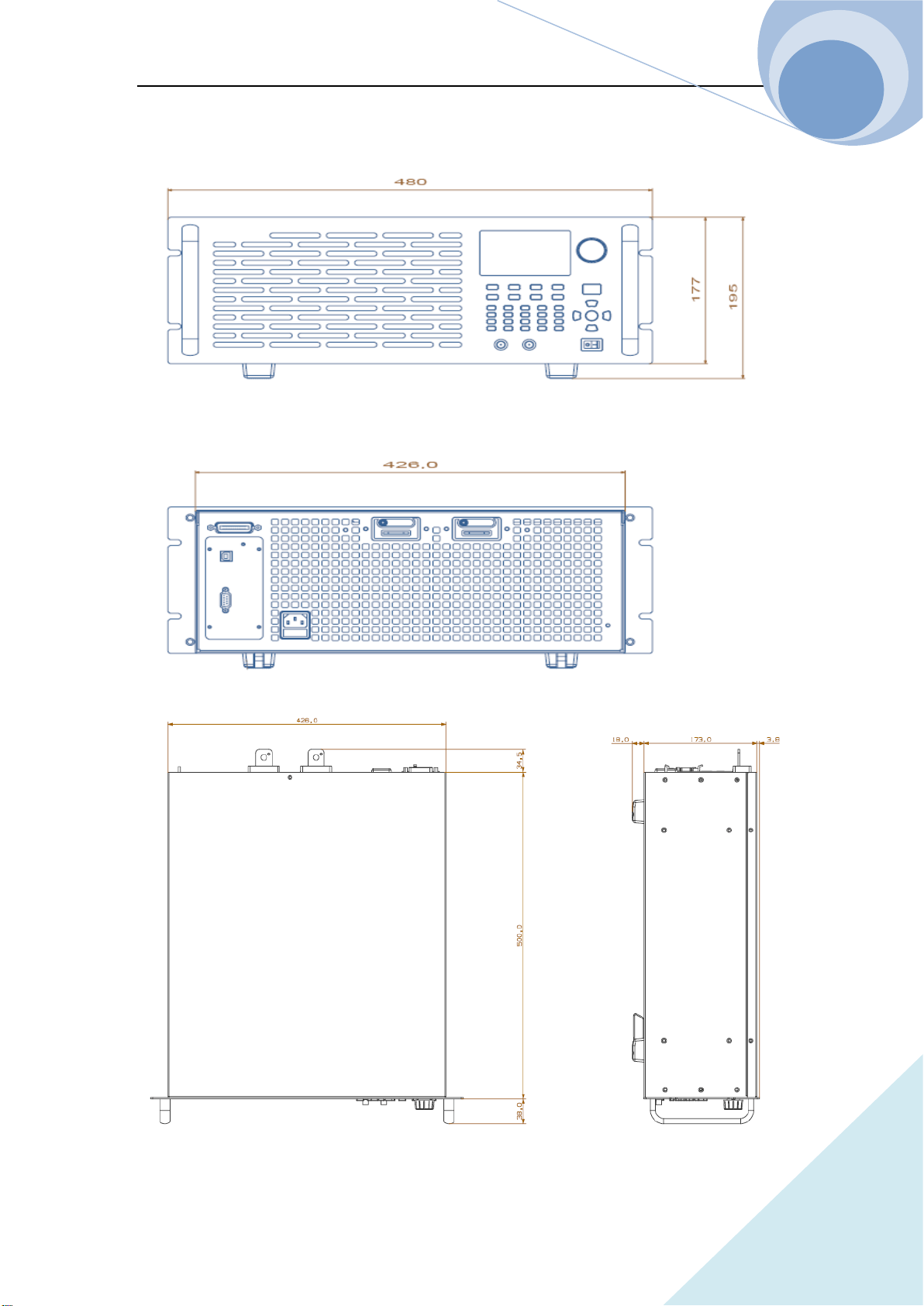
Chapter V Remote Programming Operation
110
ARRAY
Frame Diagram
Fig.1
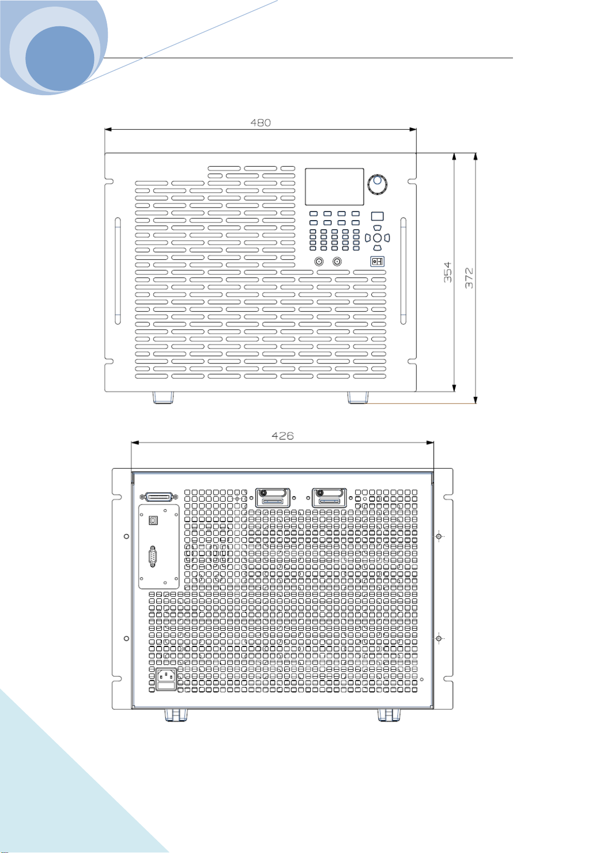
Chapter V Remote Programming Operation
111
ARRAY
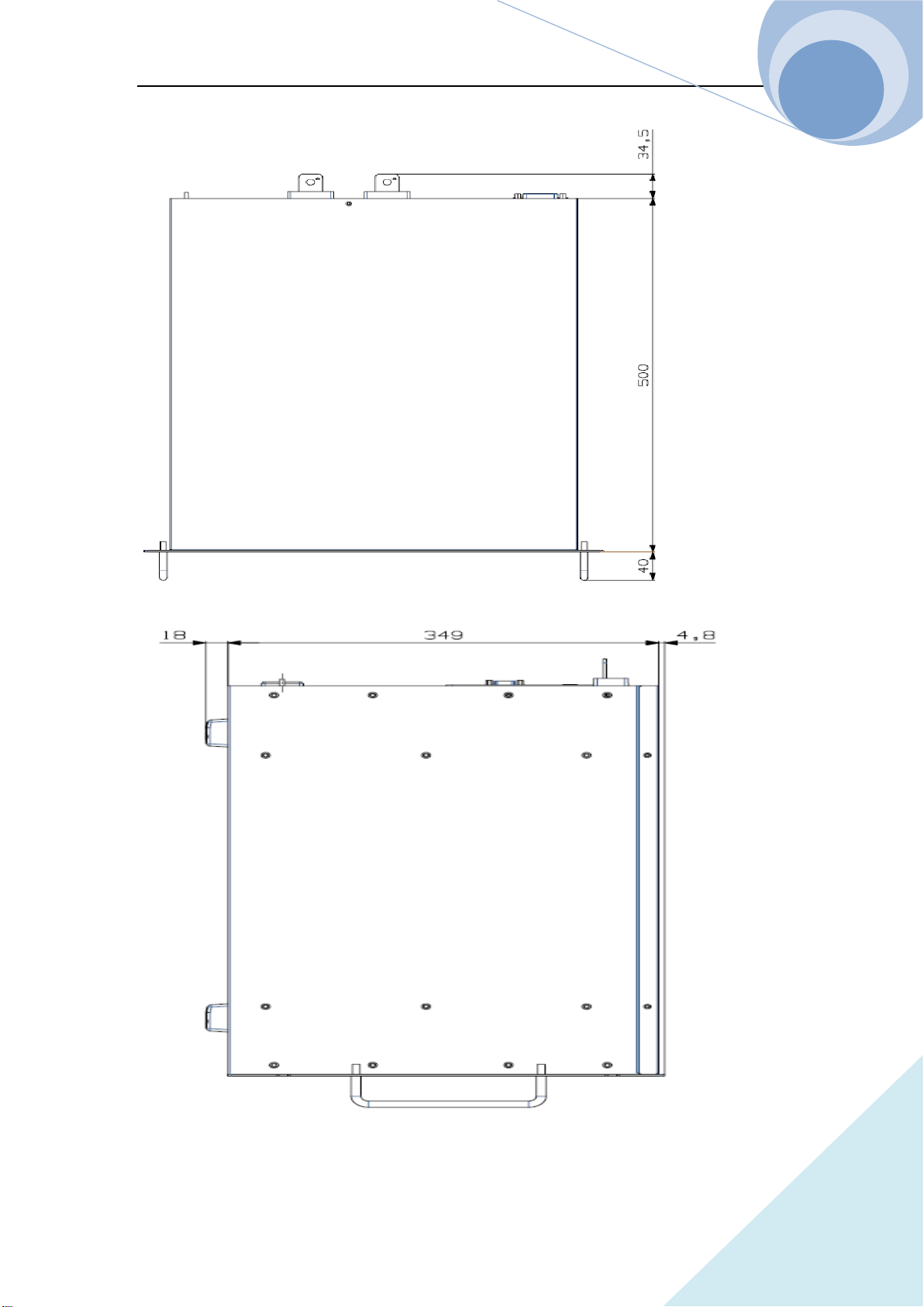
Chapter V Remote Programming Operation
112
ARRAY
Fig.2

Chapter V Remote Programming Operation
113
ARRAY
Declarations
Toxic or Hazardous Substances and Elements in Electronic Information Products
Part Name
Toxic or Hazardous Substances and Elements
Lead
(Ph)
Mercury
(Hg)
Cadmium
(Cd)
Hexavelent
Chromium
(Cr(VI))
Polybrominated
Biphenyls
(PBB)
Polybrominated
Biphenyl Ethers
(PBDE)
Shell
○ ○ ○ ○ ○ ○
PCB
Assemblies
*
× ○ ○ ○ ○ ○
Power Cable
× ○ ○ ○
○
○
CD,
Prtinting,
Packing
○ ○ ○ ○
○
○
*: PCB assemblies include the printing circuit board and its components, such like resistances,
capacitance, ICs, connectors and so on.
○: Indicates that this toxic or hazardous substance contained in all the homogeneous materials for
this part, according to EIP-A, EIP-B, EIP-C is below the limit requirement in SJ/T11363-2006.
×: Indicates that this toxic or hazardous substance contained in all the homogeneous materials for
this part, according to EIP-A, EIP-B, EIP-C is above the limit requirement in SJ/T11363-2006.
Parts with × in the above table, containing lead, because it is without mature replacement in
instrumental industrial.
Notes:
Some parts of the table may not be your standard equipment, please refer to the
actual packing box fittings shall prevail.
The start date of environmental protection period shall be based on the
production date of the product, and the parts that are unable to inquire the
production date directly from the product itself shall be based on the production

Chapter V Remote Programming Operation
114
ARRAY
date of the equipment. The environmental protection period of the products in normal
use will be up to 10 years. After the environmental protection period, please do a
good classified work to the Recyclable and Unrecyclable items to protect the
environment.

Chapter V Remote Programming Operation
115
ARRAY
RECORDS
DATE REVISION EDITION DESCRIPTION ECO NO
2016-04-13 A0 0 INITIAL VERSION N/A
2017.01.16 A1 1 ADD MODEL N/A