
1
User’s Manual
Programmable
DC Electronic Load
372x series

2
Chapter1 General Introduction 1
1.1 Function Features ....................................................................................................................... 1
1.2 Front Panel ............................................................................................................................... 2
1.3 Rear Panel .................................................................................................................................. 2
1.4 Keypad Function ........................................................................................................................ 3
1.5 Annunciators .............................................................................................................................. 4
1.6 Menu .......................................................................................................................................... 4
1.6.1 Main Menu ...................................................................................................................... 4
1.6.2 Mode and Parameter Setting Menu ................................................................................. 5
1.6.3 Transient Operation Menu ............................................................................................... 6
1.6.4 Sequence (List) Operation Menu .................................................................................... 6
1.7 Display Messages ....................................................................................................................... 7
1.8 Remote Programming ................................................................................................................ 9
Chapter2 Functions and Features ........................................................................................................... 10
2.1 Local and Remote Control ....................................................................................................... 10
2.2 Programmable Features ............................................................................................................ 10
2.3 Basic Test Function .................................................................................................................. 10
2.3.1 Constant Current Mode (CC) ........................................................................................ 11
2.3.1.1 Setting Ranges .................................................................................................... 11
2.3.1.2 Immediate Current Level .............................................. 11 错误!未定义书签。
2.3.1.3 Triggered Current Level ..................................................................................... 11
2.3.1.4 Transient Current Level ...................................................................................... 12
2.3.1.5 Software Current Limit ...................................................................................... 12
2.3.2 Constant Voltage Mode (CV) ........................................................................................ 12
2.3.2.1 Setting Ranges .................................................................................................... 12
2.3.2.2 Immediate Voltage Level .................................................................................... 12
2.3.2.3 Triggered Voltage Level ..................................................................................... 13
2.3.2.4 Transient Voltage Level ...................................................................................... 13
2.3.3 Constant Resistance Mode (CR) ................................................................................... 13
2.3.3.1 Setting Ranges .................................................................................................... 14
2.3.3.2 Immediate Resistance Level ............................................................................... 14
2.3.3.3 Triggered Resistance Level ................................................................................ 14
2.3.3.4 Transient Resistance Level ................................................................................. 14
2.3.4 Constant Power Mode (CP)........................................................................................... 14
2.3.4.1 Setting Ranges .................................................................................................... 15
2.3.4.2 Immediate Power Level ..................................................................................... 15
2.3.4.3 Triggered Power Level ....................................................................................... 16
2.4 Transient Operation .................................................................................................................. 16
2.4.1 Continuous Transient Operation .................................................................................... 16
2.4.2 Pulsed Transient Operation ........................................................................................... 17
2.4.3 Toggled Transient Operation ......................................................................................... 19
2.5 Sequence (List) Operation ........................................................................................................ 20
2.6 Battery Discharge Operation .................................................................................................... 21
2.7 Short Circuit Operation ............................................................................................................ 22

3
2.8 Triggered Operation ................................................................................................................. 22
2.9 Input Control ............................................................................................................................ 23
2.9.1 Turn On/Off the Load .................................................................................................... 23
2.9.2 Von Point/Von Latch ..................................................................................................... 23
2.9.3 Current Limit in CV Mode ............................................................................................ 24
2.9.4 Current Rise Rate .......................................................................................................... 25
2.9.5 Current Fall Rate ........................................................................................................... 25
2.10 Measurement Function ........................................................................................................... 26
2.11 Saving and Recalling .............................................................................................................. 26
2.12 Reading Remote Programming Errors ................................................................................... 27
2.13 Status Report .......................................................................................................................... 27
2.14 Protection Function ................................................................................................................ 28
2.14.1 Clearing Latched Protection ........................................................................................ 28
2.14.2 Overvoltage ................................................................................................................. 28
2.14.3 Overcurrent ................................................................................................................. 28
2.14.4 Overpower ................................................................................................................... 29
2.14.5 Overtemperature .......................................................................................................... 29
2.14.6 Reverse Voltage ........................................................................................................... 29
2.15 Auxiliary Functions ................................................................................................................ 29
2.15.1 Trigger Function Selection .......................................................................................... 29
2.15.2 Knob Function ............................................................................................................. 29
2.15.3 Key Sound ................................................................................................................... 29
Chapter3 Installation .............................................................................................................................. 30
3.1 Initial Check ............................................................................................................................. 30
3.2 Environment/Installation Location ......................................................................................... 30
3.3 Power-On/ Self-Test ............................................................................................................... 30
3.4 Connections on the Rear Panel ................................................................................................ 31
3.5 Connections on the Front Panel ............................................................................................... 32
3.6 Wiring....................................................................................................................................... 32
Chapter 4 Local Operation ..................................................................................................................... 34
4.1 Local Control ........................................................................................................................... 34
4.2 Main Operation on the Front Panel .......................................................................................... 34
4.3 Connecting to the Power Supply .............................................................................................. 34
4.4 Turning the Input On/Off ......................................................................................................... 35
4.5 Basic Tests ................................................................................................................................ 35
4.5.1 CC Mode ....................................................................................................................... 35
4.5.2 CV Mode ....................................................................................................................... 37
4.5.3 CR Mode ....................................................................................................................... 38
4.5.4 CP Mode ........................................................................................................................ 40
4.5.5 Continuous Transient Operation .................................................................................... 43
4.5.6 Pulsed Transient Operation ........................................................................................... 45
4.5.7 Toggled Transient Operation ......................................................................................... 46
4.6 Sequence (List) Operation ........................................................................................................ 48
4.6.1 Sequence (List) Editing ................................................................................................. 49

4
4.6.2 Modifying, Adding, Inserting, Deleting the Sequence (List) ........................................ 51
4.6.Starting/Stopping the Sequence (List) .............................................................................. 52
4.7 Battery Discharge Operation .................................................................................................... 53
4.8 Saving and Recalling .............................................................................................................. 55
4.9 Clear Protection Settings .......................................................................................................... 56
4.10 Error Messages ....................................................................................................................... 56
4.11 Triggered Operation ............................................................................................................... 56
4.12 Main Menu ............................................................................................................................. 57
4.12.1 Loading Default Values ............................................................................................... 57
4.12.2 Short Circuit Operation ............................................................................................... 57
4.12.3Von Point/Von Latch .................................................................................................... 58
4.12.4 Current Limit in CV Mode .......................................................................................... 59
4.12.5 Current Rise/Fall Rate in CC Mode ............................................................................ 59
4.12.6 Trigger Function Selection .......................................................................................... 60
4.12.7 Knob Function ............................................................................................................. 60
4.12.8 Key Sound ................................................................................................................... 61
4.12.9 Communication Interface ............................................................................................ 61
Chapter5 Remote Programming Operation ............................................................................................ 62
5.1 Communication Interface ......................................................................................................... 63
5.1.1 RS232 ............................................................................................................................ 63
5.1.2 USB ............................................................................................................................... 63
5.1.3 GPIB .............................................................................................................................. 63
5.2 Flow Control Selection ............................................................................................................ 63
5.3 Remote Control Annunciators .................................................................................................. 63
5.4 Sending a Remote Command ................................................................................................... 63
5.5 Returning Data ......................................................................................................................... 63
5.6 Remote Programming Commands ........................................................................................... 64
5.6.1 Modes ............................................................................................................................ 64
5.6.2 Transient Levels ............................................................................................................ 64
5.6.3 Programmable Current Protection ................................................................................. 64
5.7 CV Mode Example ................................................................................................................... 64
5.8 CR Mode Example ................................................................................................................... 64
5.9 Continuous Transient Operation Example ............................................................................... 65
5.10 Pulsed Transient Operation Example ..................................................................................... 65
Specifications ....................................................................................................................................... 656

1
Chapter1 General Introduction
ARRAY 372x Series programmable electronic load, as a new generation product of ARRAY
Electronic Co., Ltd., is designed with high performance. It provides you powerful test function,
user-friendly HMI, as well as RS232, USB, GPIB interfaces to support SCPI and Labview. 372x Series
is widely used in aerospace, shipbuilding, automotive electronics, solar cell, and fuel cell etc. scientific
research and production field.
All “electronic load” and “load” appear in this manual refer to ARRAY 372x Series Electronic
Load if there is no special explanation.
1.1 Function Features
Main function and features of ARRAY372x Series:
z 4 basic functions: CC,CV, CR, and CP; 8 basic test modes: CCL, CCH, CV, CRL, CRM,
CRH, CPV, CPC;
z The 24 bit A/D and 17 bit D/A converters incorporated, provide this equipment with greatly
enhanced setting and measurement resolution. 100kHz D/A conversion rate fully improves
high-speed performance;
z Minimum operating voltage is less than 0.6V at the load's full rated current. With optional
low-voltage testing devices, the maximum current can be achieved even though the input
voltage is 0V. This is especially suitable for fuel cell, solar cell and other new energy test
applications;
z Perfect protection assures high reliability in the most complicated of test environments;
z Innovative design of CPV and CPC modes effectively improves the practicability of CP
mode;
z Circuit improvement greatly enhances the dynamic response of CR mode and widens the
application scope of that mode;
z High-speed transient operation with separate high/low level time and rising/falling time
control;
z Powerful sequential test function; with a minimum step time of 10us; and a maximum step
time of 10000s. Cyclic numbers can be adjusted freely and a sequence can be chained to
another sequence to achieve even more complex test procedures;
z The input binding posts with their innovative design are especially suitable for large current
testing;
z Provides short-circuit test, battery discharge test and other auxiliary functions;
z A high-efficiency, intelligent cooling system can effectively reduce system temperature and
enhance power density;
z Automatic ON/OFF function simplifies test operation;
z Knobs and digital keypad makes the operation more convenient;
z Save/recall function can save multiple groups of general settings;
z Supports SCPI (Standard Commands for Programmable Instrumentation) and Labview, and
provides necessary PC software;
2
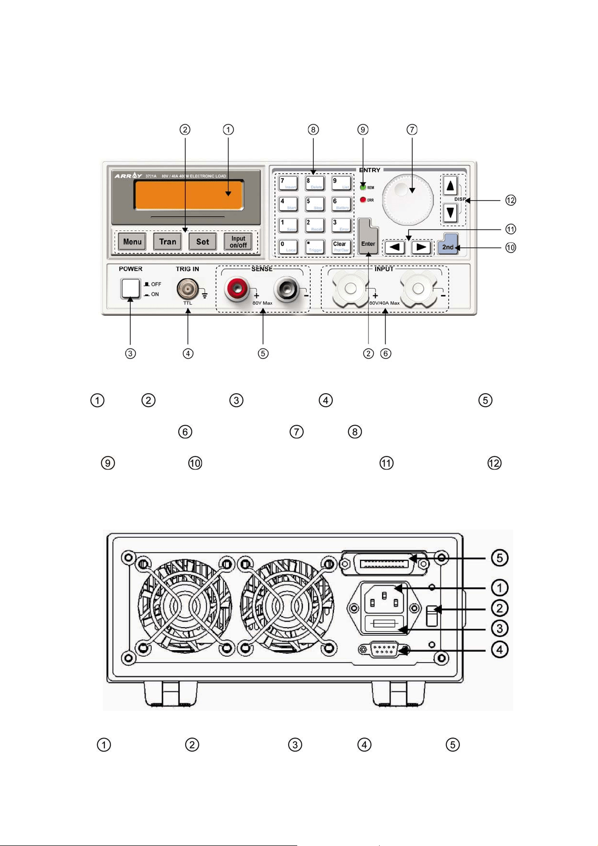
1.2 Front Panel
Fig. 1-1 Front Panel
LCD Function key Power switch External trigger input terminal Remote
sense terminal Input binding posts Knob Entry keys/secondary function keys
Annuciators Switch key for secondary function Left&Right key Up &
Down key/Display-switching key
1.3 Rear Panel
Fig1-2 Rear Panel
AC input socket Line voltage switch Fuse holder RS232 Interface GPIB or USB
3
(optional)
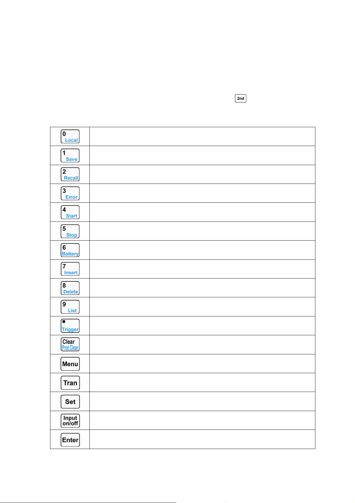
1.4 Keypad Function
There are three groups of keypads on the front panel: the Function Keys, the Entry Keys, which
composite with secondary functions, and the Direction Keys. The secondary functions of the Entry
Keys are printed in blue. To use the secondary function, please press
key first, then press the
relevant key.
List 1-1 Description for Keys
0/Local key
1/Save key
2/Recall key
3/Error code display key
4/Sequence (list) start key
5/Sequence (list) stop key
6/Battery discharge operation key
7/Insert key
8/Delete key
9/Sequence (list) operation key
Decimal point/Trigger key
Clear or exit /Clear protection
Main Menu
Transient operation menu
Set key
Input on/off
Confirm key

4
Left key
Right key
Up key
Down key
Switch key for secondary function
Note: Up and Down key can be used as a switch key for displaying load status and actual power
during basic test modes.
1.5 Annunciators
REM
Indicates that the electronic load is in remote status.
ERR
Indicates that a remote programming error(s) has occurred.
1.6 Menu
1.6.1 Main Menu
Press key to enter into main menu. Please see the list below for main menu content:
Function and Parameter Description
Load Default
Yes *No
Restore default
Yes No
Short
On *Off
Short circuit mode
On Off
Von Latch
On *Off
Von latch
On Off
Von Point
0.000v
Set Von voltage point
Von point
CV Curr Limit
40.00A
Current limit in CV mode
Current limit
Curr Rise Rate
4.000A/us
Current rise rate in CC mode
Current rise rate
Curr Fall Rate
4.000A/us
Current fall rate in CC mode
Current fall rate
Trig Function
*Tran List
Trigger function selection
Transient test Sequence (list) test
Knob
*On Off
Enable/disable knob function
On Off
Key Sound
*On Off
Enable/disable key sound
On Off
5
Interface
*RS232 USB GPIB
Remote interface selection
RS232 USB GPIB
RS232 Interface
Baud Rate
2400 4800 *9600 19200 38400
Baud rate setting
2400 4800 9600 19200 38400
Parity Check
*None Even Odd
Parity check setting
None Even Odd
Data Bit
*8 7
Data bits length
8bits 7bits
Stop Bit
*1 2
Stop bit length
1bit 2bits
Flow Control
*On Off
Enable/disable Flow control
On Off
USB Interface
USB selection
GPIB Interface
GPIB Address
5
GPIB address
Address value
Note: Except knob, key sound and interface configurations, the other parameters in main menu
will not be saved when the load is turned off. If it is needed to save the parameters, please use
key or *sav command. When the load is turned on next time, the saved parameters in location 0 will be
recalled automatically.
1.6.2 Mode and Parameter Setting Menu
Press key to enter into mode and parameter setting menu, which is shown as below:
Function and Parameter Description
MODE:CCL
CURR: 0.000A
Constant current low range
Immediate current level
MODE:CCH
CURR: 0.000A
Constant current high range
Immediate current level
MODE:CV
VOLT: 80.00V
Constant voltage mode
Immediate voltage level
MODE:CRL
RES: 2.000Ω
Constant resistance low range
Immediate resistance level
MODE:CRM
RES: 20.000Ω
Constant resistance medium range
Immediate resistance level
MODE:CRH
RES: 20.000Ω
Constant resistance high range
Immediate resistance level
MODE:CPV
POWR: 0.000W
Constant power-voltage source mode
Immediate power level
MODE:CPC
POWR: 0.000W
Constant power-current source mode
Immediate power level
6
1.6.3 Transient Operation Menu
Press key in desired mode to enable its transient operation, and press key to enter
into transient setting menu, which is shown as below:
Function Description Example
LevelL Transient low level 1.000A
LevelH Transient high level 2.000A
TimeL Time for transient low level 600.00ms
TimeH Time for transient high level 600.00ms
TimeR Time for transient rising edge 0.01ms
TimeF Time for transient falling edge 0.01ms
MODE Continuous (Cont) Pulse (Puls) Toggle
(Togg)
Cont
Note: Transient operation may be used in CC, CV, and CR modes.
1.6.4 Sequence (List) Operation Menu
Press key and then press to enter into the list operation menu, which is shown as
below:
Function Description
No. Select sequence (list) number
(0-6)
Memo Sequence memo (10
characters)
Data: <New/Edit> Create a new or edit an existing
sequence
Count Cycle times(1-65535)
Chain: Off Sequence number to be
chained with (0-6,off)
Press and keys in sequence (list) operation menu to select Data: <New/Edit>, and
select New or Edit with the knob or
and keys. Then press key to enter into sequence
data editing status, which is shown as below:
Function Description
01. 10000.00000s
CCH 5.000A
Sequence (List) number
Time
Mode Set value
7
1.7 Display Messages
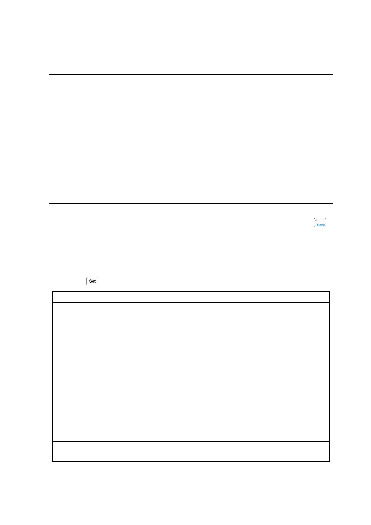
① CC Mode:
The first line shows actual voltage and current levels. The second line shows current set level, CC
mode (CCH indicates constant current high range; CCL indicates constant current low range) and
input status of the load: (ON, OFF).
② CV Mode:
The first line shows actual voltage and current levels. The second line shows voltage set
level, CV mode, and input status of the load: (ON, OFF).
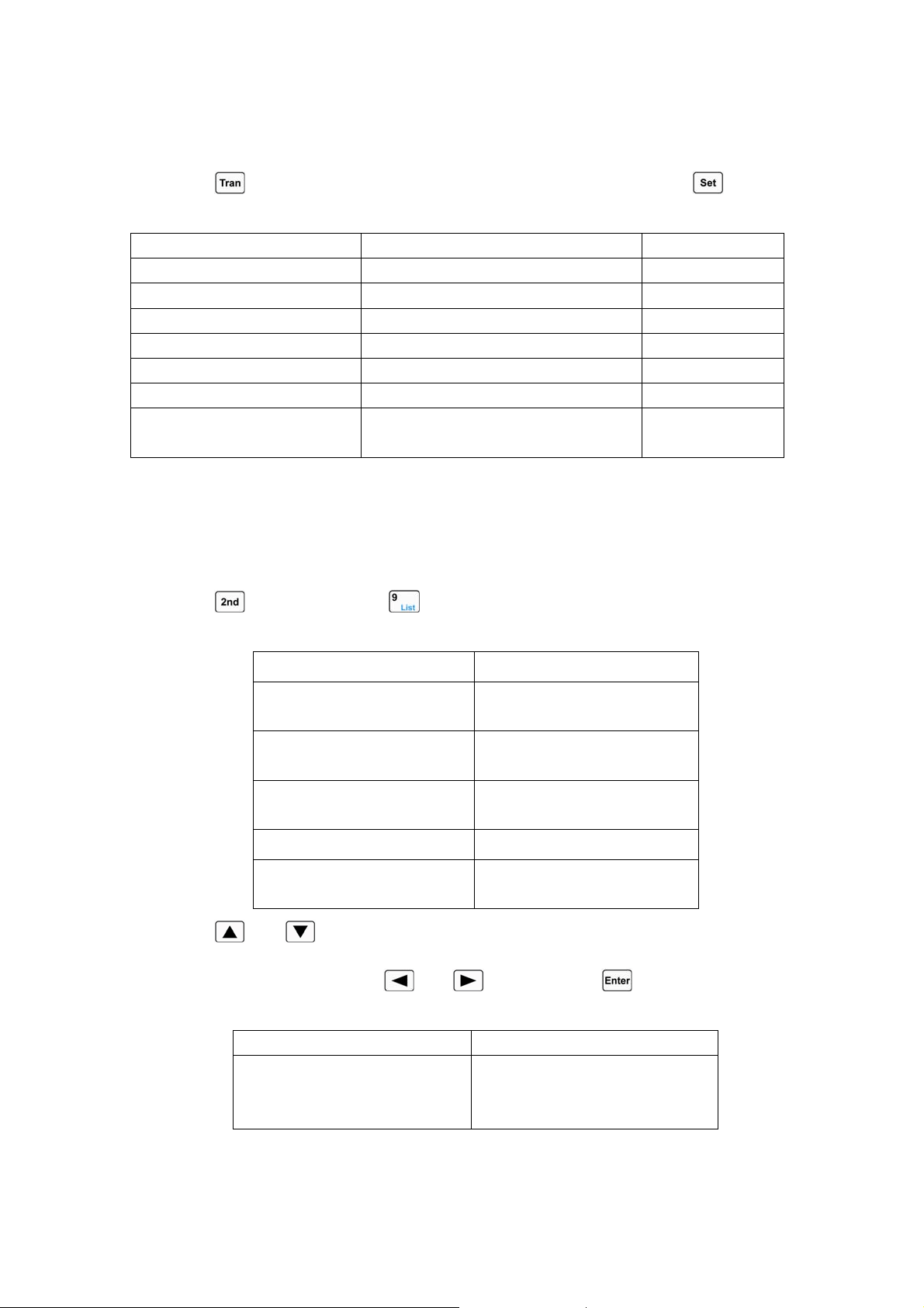
③ CR Mode:
The first line shows actual voltage and current levels. The second line shows resistance level, CR
mode (CRL indicates constant resistance low range; CRM indicates constant resistance medium range;
and CRH indicates constant resistance high range) and input status of the load: (ON, OFF).
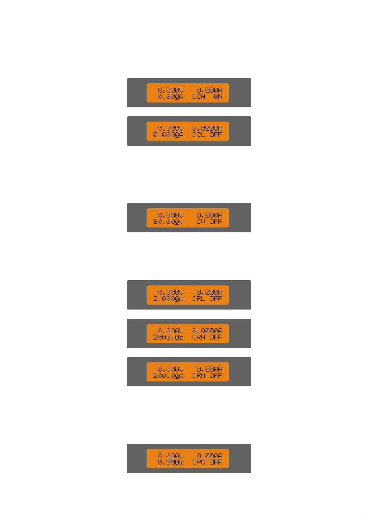
④ CP Mode:
8
The first line shows actual voltage and current levels. The second line shows power set level,
CP mode (CPC indicates constant power-current source mode; CPV indicates constant
power-voltage source mode), and input status of the load: (ON, OFF).
⑤ Transient Operation:
The first line shows actual voltage and current levels. The second line shows set level,
transient operation mode (“t” indicates transient operation), and input status of the load: (ON,
OFF).
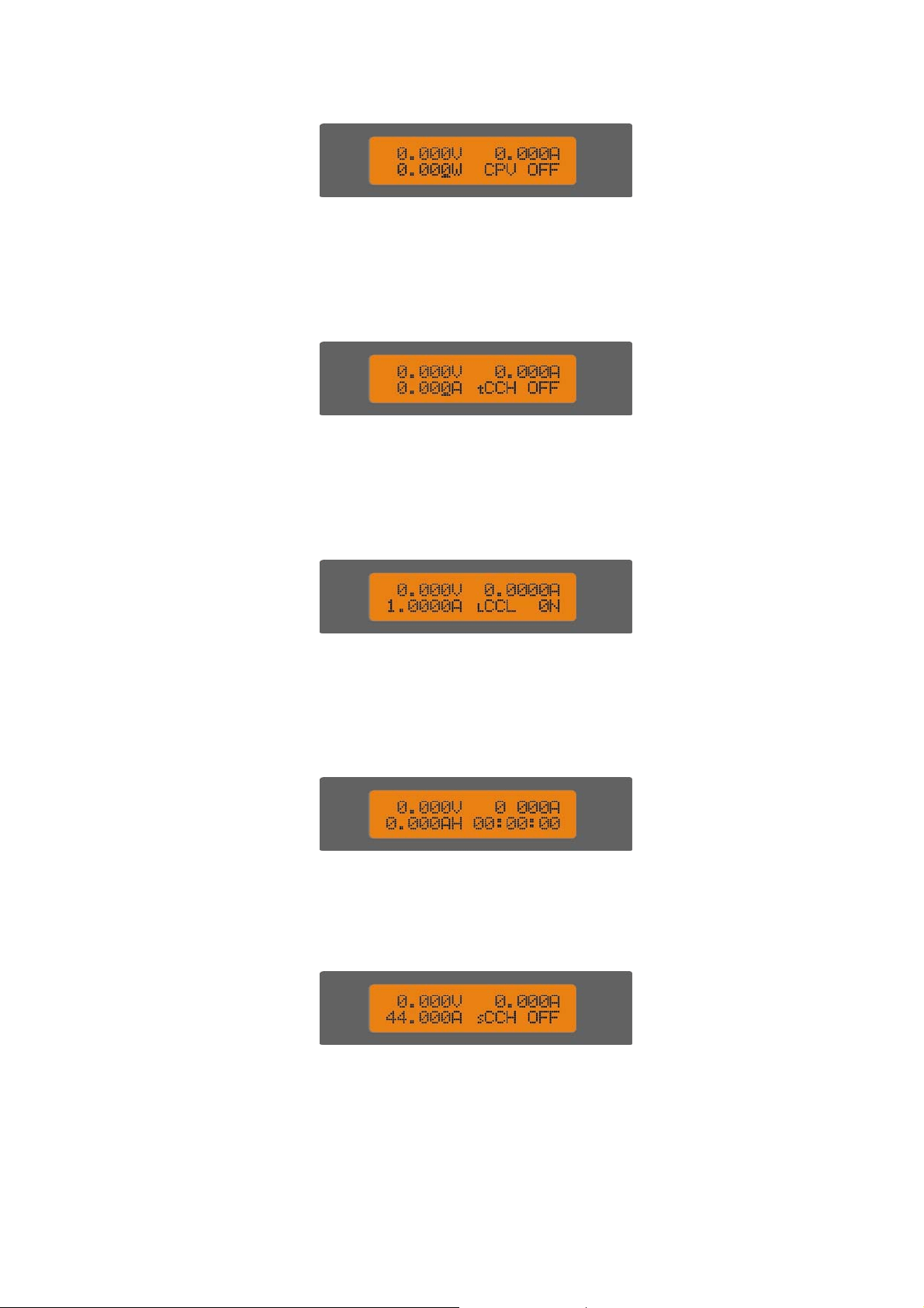
⑥ Sequence (List) Operation:
The first line shows actual voltage and current levels. The second line shows set level,
sequence operation mode (“l” indicates sequence (list) test); and input status of the load: (ON,
OFF).
⑦ Battery Discharge Operation:
The first line shows actual voltage and current levels. The second line battery capacity and
discharge time.
⑧ Short Circuit Operation:
The first line shows actual voltage and current levels. The second line shows set level in
short circuit, short circuit operation mode ( “s” indicates short circuit test), and input status of the
load (ON, OFF).
⑨ Display Actual Power:
9
Pressing
and key can switch the display of load status and actual power. On the
display screen of actual power, the first line shows actual voltage and current; the second line
shows set level and actual power level.
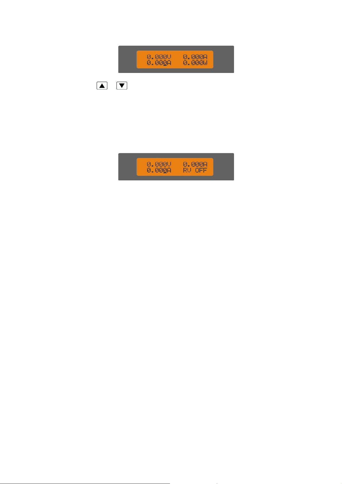
⑩ Protection Status
If the protection function is active, LCD will display corresponding protection status. For
example: the display of reverse voltage protection status is shown as below:
Protection status includes overcurrent (OC), overvoltage (OV), overpower (OP), over temperature
(OT), load protection (PT), and reverse voltage (RV).
1.8 Remote Programming
The commands are sent to electronic load via remote interface (RS232, GPIB, USB), and will be
executed after decoding by the processor. If there is any error occurs to the command, the processor
can detect the wrong command and error type, and it can maintain the status register as well.

10
Chapter2 Functions and Features
The functions and features of electronic load will be described in this chapter, which helps you to
know ARRAY 372x series better.
2.1 Local and Remote Control
ARRAY 372x series electronic load can be controlled via the front panel, or by remote controller
via remote interface. If it is needed to control the load via the front panel, the load has to stay in local
control status.
Local (front panel) control is in effect immediately after power is applied. Remote control
goes into effect as soon as the load receives a command via the GPIB or a
SYSTem:REMote command via
RS232
.
Under remote control status, the REM annunciator is turned on, all operations on front panel
keypad and knobs become invalid (except , keys). All operations on electronic load are
controlled by remote controller. The electronic load will return to local control and REM remote
control annunciator is turned off after receiving the return command (e.g. : SYST:LOC). Or you can
return the electronic load to local control by pressing
and keys.
Details of local operation are covered in Chapter 4 - Local Operation and fundamentals of remote
programming are given in Chapter 5 - Remote Operation. Complete
SCPI programming details are given in
the ARRAY 372x Series Electronic Load SCPI Programming Guide.
2.2 Programmable Features
Main functions(features) of electronic load:
z CC(
constant current) Mode (CCL, CCH)
z CV(
constant voltage) Mode (CV)
z CR(
constant resistance) Mode (CRL, CRM, CRH)
z CP(
constant power) Mode (CPV, CPC)
z Transient Operation (Tran)
z Sequence (List) Operation
z Battery Discharge Operation (Battery)
z Short Circuit Operation (Short)
2.3 Basic Test Function
There are four modes of operation:
constant current(CC), constant voltage(CV), constant
resistance(CR), constant power(CP).
The test mode and
the associated parameters can be set via front panel or remote command. The
load will
remains in that mode until the mode is changed. If the mode is changed when the load’s
input is in ON status, the load will be turned off for around 5ms automatically.
The set value for electronic load becomes effective immediately when the load is turned on. If the
11
input set value exceeds the allowed range, it will be automatically limited at maximum value or
minimum value.
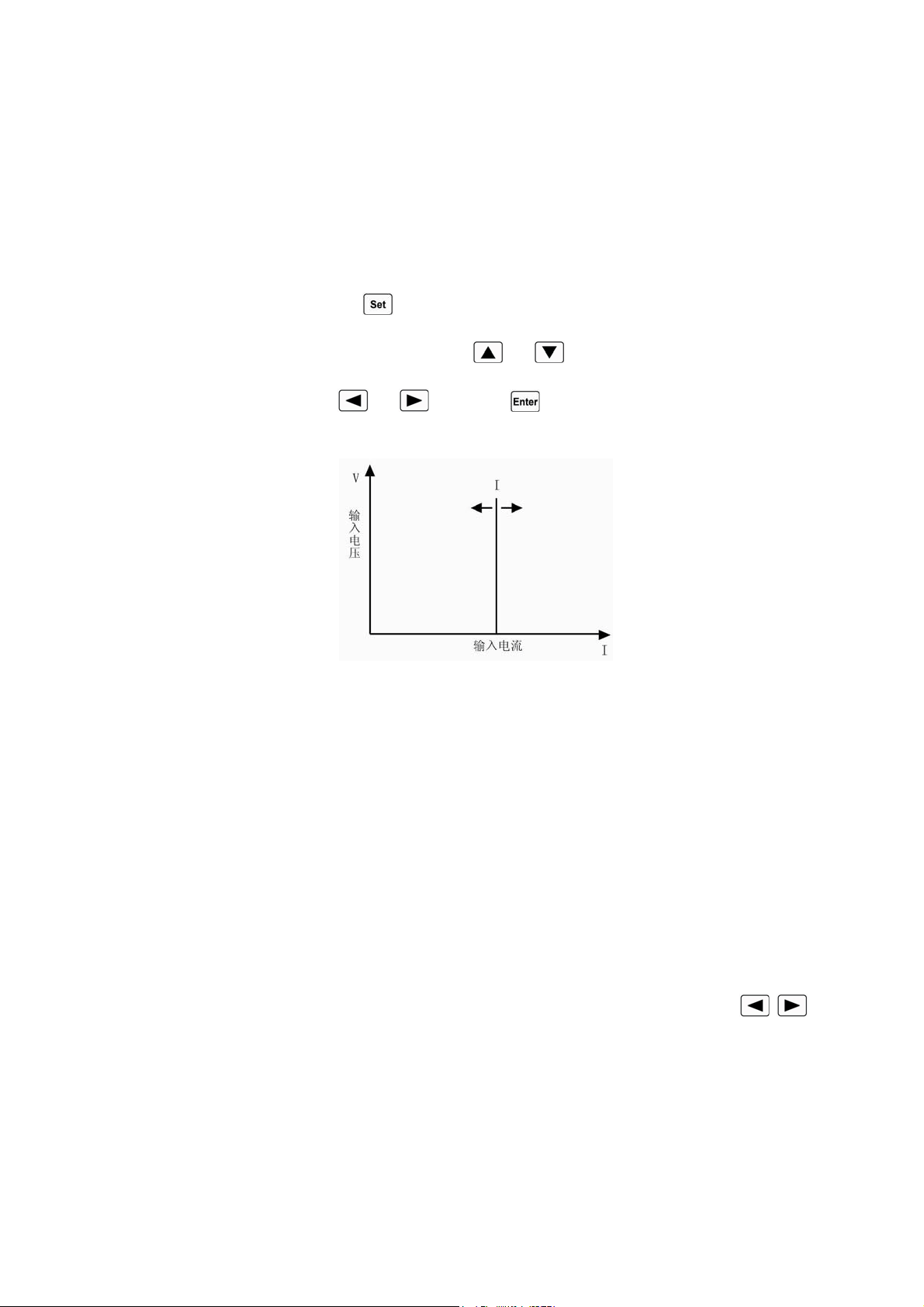
2.3.1 Constant Current Mode
Constant current mode has two ranges, the high range(CCH) and the low range(CCL). The high
range provides wider test range.
The low range provides better resolution at low current settings. In
CC mode,
the load will sink a current in accordance with the programmed value regardless of the
input voltage
(see fig.2-1). Press key in basic mode to enter into mode selection and parameter
setting menu. Choose CCH or CCL mode with
and keys. Input the current level via the
Entry keys or the knob with
and keys. Use key for confirmation. The CC mode and
parameters can also be set via remote command (MODE CCL, MODE CCH, CURRent <NRf+>).
Fig.2-1 CC Mode
2.3.1.1 Setting Ranges
In constant current low range (CCL), the current setting range is 0~4A; in constant current high
range (CCH), the current setting range is 0~40A. If the range is changed in CC mode while the load’s
input stays ON status, the load will be turned off for around 5ms automatically. For example: when the
load is switched from CCL to CCH, the input will be turned off around 5ms. Besides, it is noted that
the current set level may have changed to fit the new range when the current range is changed. For
example: the present setting is CCH 10.000A, when the load is switched from CCH to CCL, the
current set level will change to the maximum level 4.0000A for CCL.
2.3.1.2 Immediate Current Level
The immediate current level refers to the current set value in CC mode, which can be
programmed via mode selection and parameter setting menu, or via remote command (CRRRent
<NRf+>). The immediate current level can also be modified directly with left/right keys (
)
and the knob.
2.3.1.3 Triggered Current Level
The triggered current level refers to the preset current value, which can become immediate
current level automatically when a trigger is received. If the CC mode and the input are enabled, the
input will be updated immediately when a trigger occurs. If the CC mode is not active, this current
12
level will have no effect on the input until the CC mode becomes active.The triggered current level
only can be set via remote command (CURRent:TRIGgered <NRf+>).Once a current level is triggered,
subsequent triggers will become invalid until another (CURRent:TRIGgered <NRf+>) command is
received. The trigger sources available to the load will be
described in later chapter. The electronic load
has a status register, which can keep track of pending triggers and other operating conditions. This
status register will be described in details in the “ARRAY 372x Series Electronic Load SCPI
Programming Guide”.
2.3.1.4 Transient Current Level
The load will switch between the transient high current level (LevelH) and transient low current
level (LevelL) when the transient operation is enabled. The transient current level can be set in
transient operation menu from the front panel, or via remote command (CURRent:HLEV <NRf+>,
CURRent:LLEV <NRf+>).
2.3.1.5 Software Current Limit
The electronic load allows the user to set a current limit (0~40A) via remote command
(CURRent:PROTection <NRf+>). The load will be turned off with beeping alarms if the current limit
is exceeded beyond a programmable time delay (0.001-60s). Please note that the software current limit
is in effect for any mode of operation.
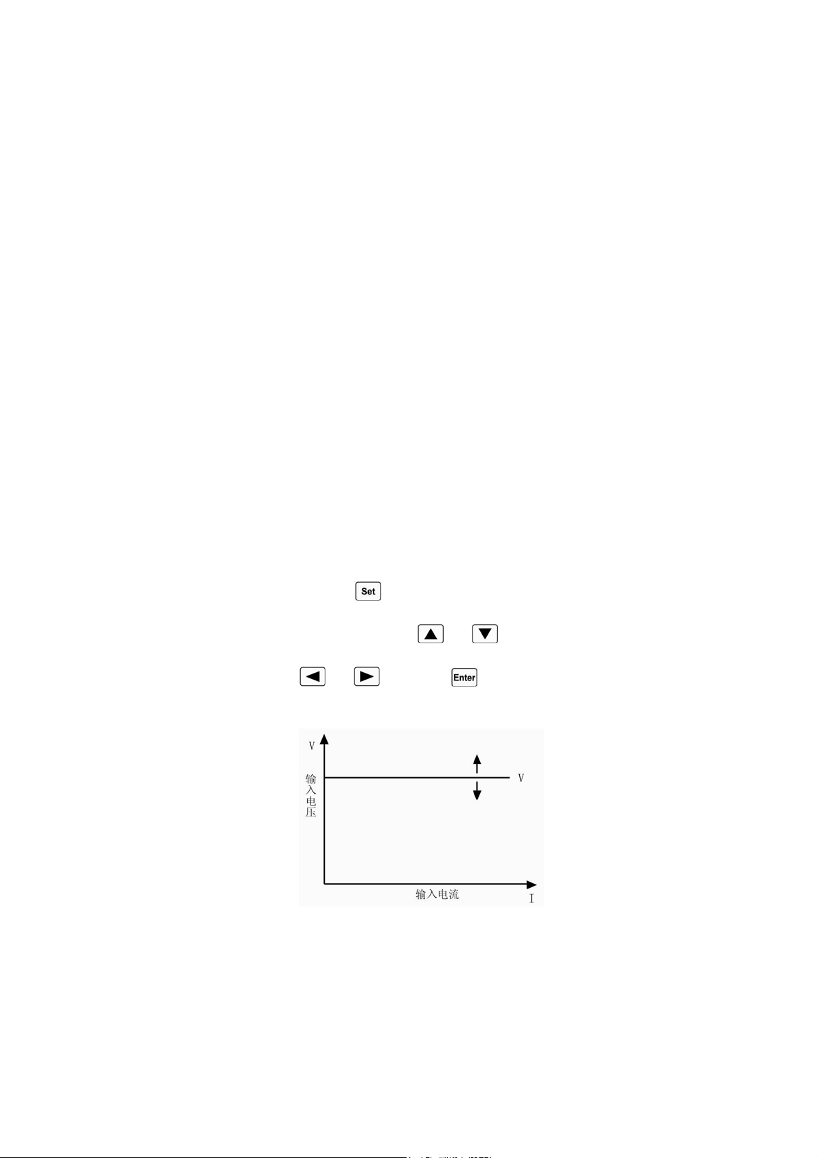
2.3.2 Constant Voltage Mode (CV)
In CV mode, the load
will attempt to sink enough current to control the source voltage to the
programmed value
(see fig.2-2). Press key in basic mode to enter into mode selection and
parameter setting menu. Choose CV mode with
and keys. Input the voltage value via the
Entry keys or the knob with
and keys. Use key for confirmation. The CV mode and
parameters can also be set via remote command (MODE CV, VOLTage <NRf+>).
Fig.2-2 CV Mode
2.3.2.1 Setting Ranges
The voltage setting range is 0~80V.
2.3.2.2 Immediate Voltage Level
The immediate voltage level refers to the voltage set value in CV mode, which can be set via
13
mode selection and parameter setting menu, or via remote command (VOLTage <NRf+>). The
immediate current level can also be modified directly with left/right keys (
) and the knob.
2.3.2.3 Triggered Voltage Level
The triggered voltage level refers to the preset voltage value, which can become immediate
voltage level automatically when a trigger is received. If the CV mode and the input are enabled, the
input will be updated immediately when a trigger occurs. If the CV mode is not active, this voltage
level will have no effect on the input until the CV mode is active.
The triggered voltage level only can be set via remote command (VOLTage:TRIGgered
<NRf+>).Once a voltage level is triggered, subsequent triggers will become invalid until another
(VOLTage:TRIGgered <NRf+>) command is received. The trigger sources available to the load will
be
described in later chapter. The electronic load has a status register, which can keep track of pending
triggers and other operating conditions. This status register will be described in details in the
“ARRAY 372x Series Electronic Load SCPI Programming Guide”.
2.3.2.4 Transient Voltage Level
The load will switch between the transient high voltage level (LevelH) and transient low voltage
level (LevelL) when the transient operation is enabled. The transient voltage level can be set in
transient operation menu from the front panel, or via remote command (VOLTage:HLEVel <NRf+>,
VOLTage:LLEVel <NRf+>).
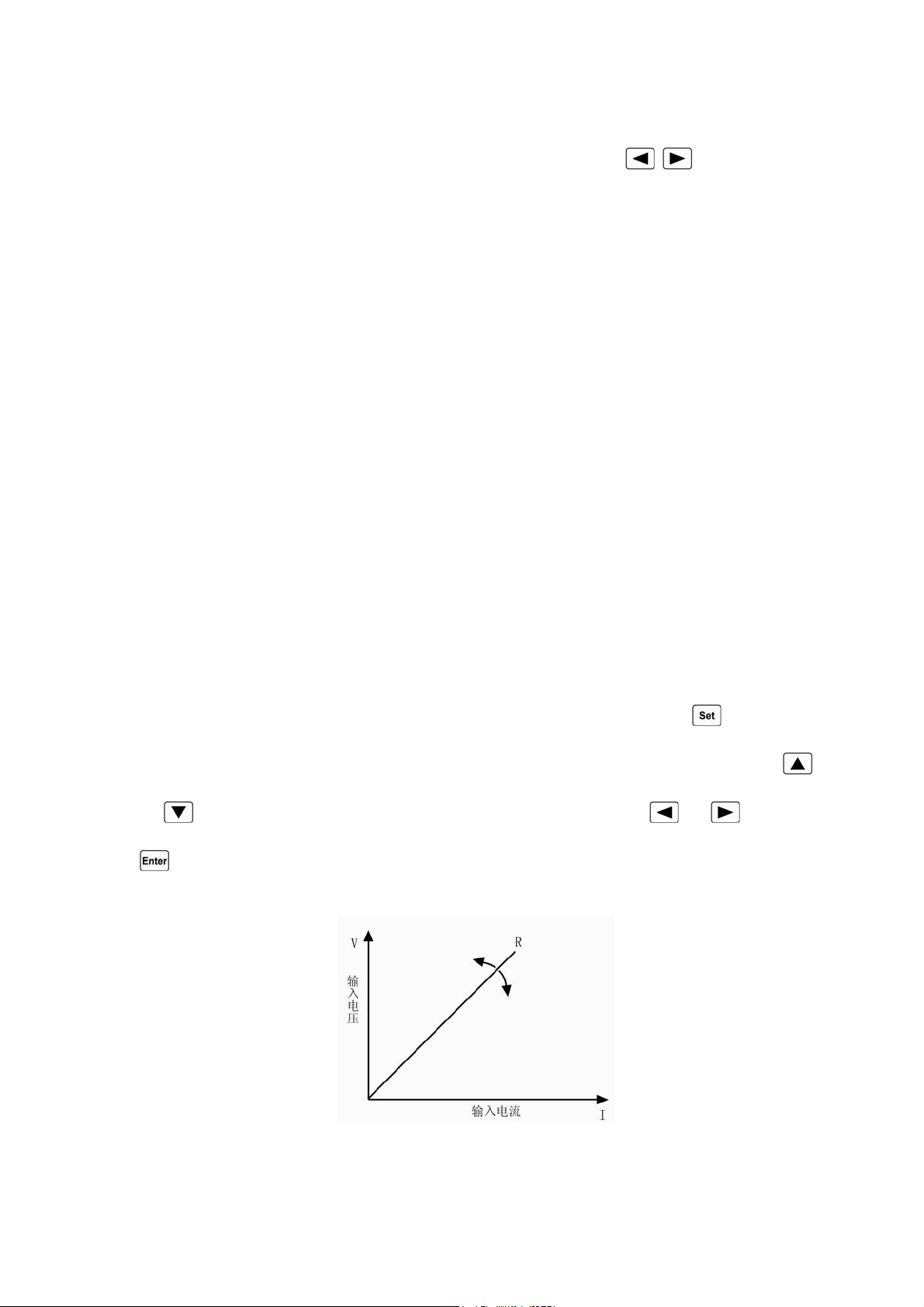
2.3.3 Constant Resistance Mode (CR)
Constant resistance mode has three range: the low range (CRL), the medium range (CRM), and
the high range (CRH). In CR mode,
the load will sink a current linearly proportional to the input voltage
in accordance with the programmed resistance
to make I=U/R (see fig.2-3). Press key in basic
mode to enter into mode selection and parameter setting menu. Choose CR mode with
and
keys. Input the resistance value via the Entry keys or the knob with and keys. Use
key for confirmation. The CR mode and parameters can also be set via remote command (MODE
CRL, MODE CRM, MODE CRH, RESistance <NRf+>).
Fig.2-3 CR Mode

14
2.3.3.1 Setting Ranges
In constant resistance low range (CRL), the resistance setting range is 0.02 ~2Ω; in constant
resistance medium range (CRM), the resistance setting range is 2 ~200Ω; in constant resistance high
range (CRH), the resistance setting range is 20 ~2000Ω. If the range is changed in CR mode while the
load` s input stays ON status, the load will be turned off for around 5ms automatically. For example:
when the load is switched from CRL to CRH, the input will be turned off around 5ms. Besides, it is
noted that the resistance set level may have changed to fit the new range when the resistance range is
changed. For example: the present setting is CRM 10.000Ω, when the load is switched from CRM to
CRL, the resistance set level will change to the maximum level 2.0000Ωfor CRL.
2.3.3.2 Immediate Resistance Level
The immediate resistance level refers to the resistance set value in CR mode, which can be set via
mode selection and parameter setting menu, or via remote command (RESistance <NRf+>). The
immediate resistance level can also be modified directly with left/right keys (
) and the knob.
2.3.3.3 Triggered Resistance Level
The triggered resistance level refers to the preset resistance value, which can become immediate
resistance level automatically when a trigger is received. If the CR mode and the input are enabled, the
input will be updated immediately when a trigger occurs. If the CR mode is not active, this resistance
level will have no effect on the input until the CR mode becomes active.
The triggered resistance level only can be set via remote command (RESistance:TRIGgered
<NRf+>).Once a resistance level is triggered, subsequent triggers will become invalid until another
(RESistance:TRIGgered <NRf+>) command is received. The trigger sources available to the load
will be
described in later chapter. The electronic load has a status register, which can keep track of
pending triggers and other operating conditions. This status register will be described in details in the
“ARRAY 372x Series Electronic Load SCPI Programming Guide”.
2.3.3.4 Transient Resistance Level
The load will switch between the transient high resistance level (LevelH) and transient low
resistance level (LevelL) when the transient operation is enabled. The transient resistance level can be
set in transient operation menu from the front panel, or via remote command (RESistance:HLEVel
<NRf+>, RESistance:LLEVel <NRf+>).
2.3.4 Constant Power Mode (CP)
There are two sorts of constant power modes, the Constant Power-Voltage Source mode (CPV)
and the Constant Power-Current Source mode (CPC). The CPV mode is applied to voltage source test,
and the CPC mode is applied to current source test. In CP mode, the load consumes the constant power
in accordance with the programmed value regardless of the changes of external current and voltage
(see fig.2-4). Press
key to enter into mode selection and parameter setting menu. Choose CPV or
CPC mode with
and keys. Input the power value via Entry keys or the knob with
and
keys. Use key for confirmation. The CP mode and parameters can also be set via remote
15
command (MODE CPV, MODE CPC, POWer <NRf+>).
Fig.2-4 CP Mode
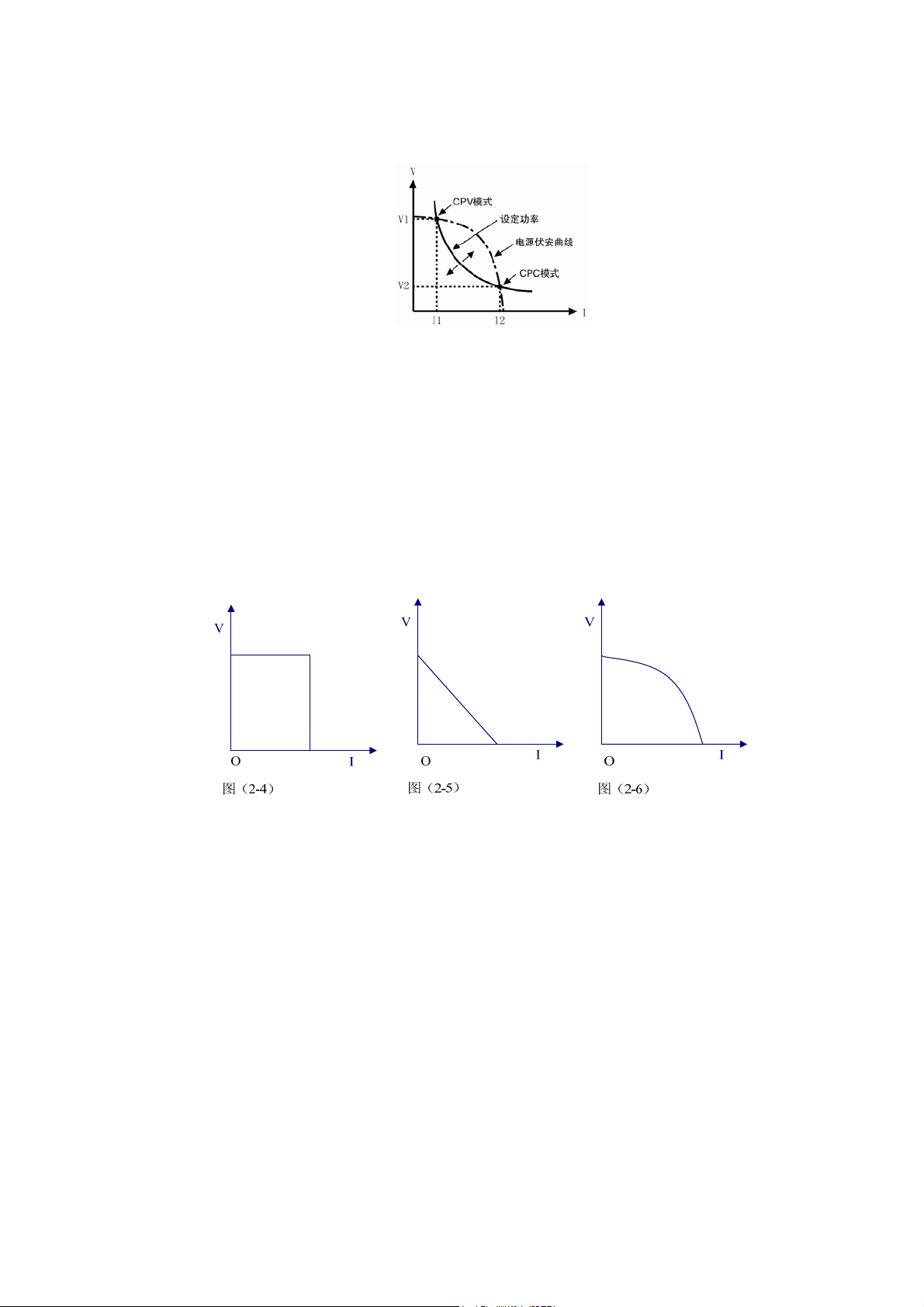
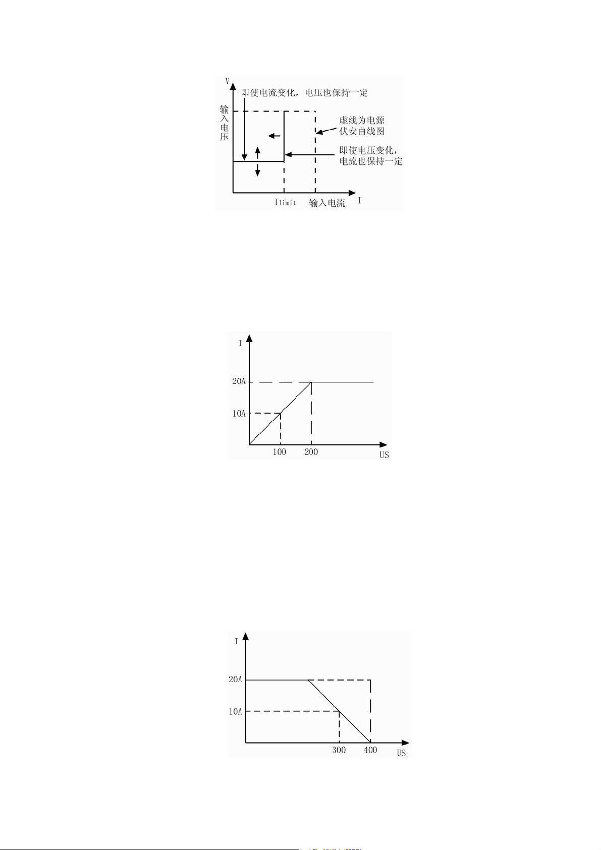
Figure 2~5 are the current-voltage curves for several common power supplies. The constant
power curve is a hyperbola in the first quadrant. The constant power curve usually intersects with
current-voltage curve at two points (the CPV point and the CPC point) when the power of the external
power supply is larger than the set power. At the CPV point, the power supply shows the feature of
voltage source: the output power will be increased with increasing current; at the CPC point, the power
supply shows the feature of current source: the output power will be increased with increasing voltage.
Array 372x series electronic load can be set at any one of intersection points to operate by the user.
Fig. 2-5 Current-voltage Curve for Normal Power Supply
As adopting advanced slope detection method, Array 372x series electronic load only has to test a
part of the current-voltage curve to know whether the two curves (constant power curve and
current-voltage curve) intersect. Therefore, when the set power is larger than the actual power, the
external power supply will not be short-circuited by the load because the power is insufficient. When
the load detects that the power of the external power supply is insufficient, the current will stop to be
increased at once, and the load will try to find constant power point again till the set power is met.
2.3.4.1 Setting Ranges
The setting range for the power is 0~400W no matter it is CPV mode or CPV mode.
2.3.4.2 Immediate Power Level
The immediate power level refers to the power set value in CP mode, which can be set via mode
selection and parameter setting menu, or via remote command (POWer <NRf+>). The immediate

16
resistance level can also be modified directly with left/right keys ( ) and the knob.
2.3.4.3 Triggered Power Level
The triggered power level refers to the preset power value, which can become immediate power
level automatically when a trigger is received. If the CP mode and the input are enabled, the input will
be updated immediately when a trigger occurs. If the CP mode is not active, this power level will have
no effect on the input until the CP mode becomes active.
The triggered power level only can be set via remote command (POWer:TRIGgered
<NRf+>).Once a power level is triggered, subsequent triggers will become invalid until another
(POWer:TRIGgered <NRf+>) command is received. The trigger sources available to the load will be
described in later chapter. The electronic load has a status register, which can keep track of pending
triggers and other operating conditions. This status register will be described in details in the “ARRAY
372x Series Electronic Load SCPI Programming Guide”。
2.4 Transient Operation
When the transient operation is enabled, the load periodically switch between two levels (LevelH
and LevelL), which can be applied to test the dynamic characteristics of the power supply. The
transient operation can be executed in the CC, CV, CR modes, and has three operating statuses:
Continuous, Pulsed, and Toggled. Please make sure the sequence (List) operation has been disabled
before enabling transient operation.
The parameters associated with transient operation are: low level (LevelL), high level (LevelH),
low level time (TimeL), high level time (TimeH), time for rising edge (TimeR), time for falling edge
(TimeF), and operating mode.
Transient high/low level and corresponding CC, CV, CR modes share one setting range.
The range for high/low level time is 0 ~ 655.35ms; the range for rising/falling edge time is 10us ~
655.35ms; the time resolution is 10us, and the maximum test frequency is 50kHz.
Transient test can be turned on and off via
key at the front panel or via remote command
(TRANsient ON/OFF). Before you turn on transient test, you should set the load to the desired mode.
Note: In transient test, the Von point and current limit should be taken into consideration, which
may cause the shut down of the input, so that the transient test is interrupted.
2.4.1 Continuous Transient Operation
In continuous operation, the load periodically switches between high/low levels. The relevant(
the
associated
) parameters such as low level (LevelL), high level (LevelH), low level time (TimeL), high
level time (TimeH), time for rising edge (TimeR), time for falling edge (TimeF), and continuous
transient operation can be set through transient operation menu or via remote command
(CURRent:LLEVel <NRf+>, CURRent:HLEVel <NRf+>, VOLTage:LLEVel <NRf+>,
VOLTage:HLEVel <NRf+>, RESistance:LLEVel <NRf+>, RESistance:HLEVel <NRf+>,
TRANsient:LTIMe <NRf+>, TRANsient:HTIMe <NRf+>, TRANsient:RTIMe <NRf+>,
TRANsient:FTIMe <NRf+>, TRANsient:MODE CONTinuous).

17
For example: assume that the CCH range is active, and the input is in OFF status, then the
transient parameters should be set as follows:
Press key to enter into transient operation;
Press
key to open transient operation menu;
Set the following parameters in transient operation menu:
LevelL: 5.000A
LevelH : 10.000A
TimeL : 0.50ms
TimeH : 0.50ms
TimeR : 0.20ms
TimeF : 0.20ms
Mode : Cont
Then press
key to turn on the input;
Or via remote command to set:
SCPI Command Description
TRAN ON Enables transient operation
CURR:LLEV 5 Sets transient current low level to 5A
CURR:HLEV 10 Sets transient current high level to 10A
TRAN:LTIM 500us Sets transient low level time to 500us
TRAN:HTIM 500us Sets transient high level time to 500us
TRAN:RTIM 200us Sets the time for transient rising edge to 200us
TRAN:FTIM 200us Sets the time for transient falling edge to 200us
TRAN:MODE CONT Selects continuous operation
INPUT ON Turns on the input
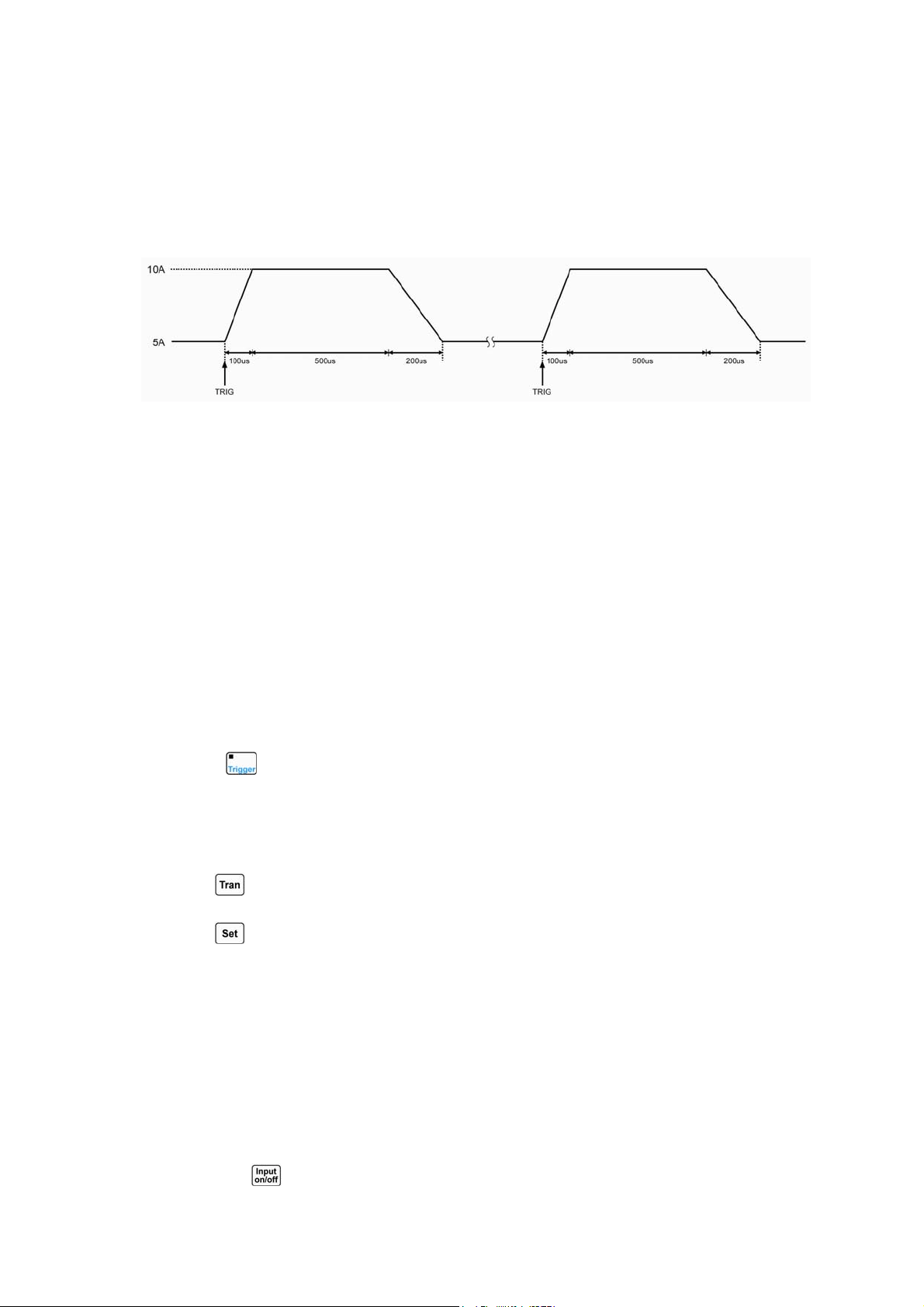
Figure 2-6 shows the current waveform of the load: the load` s input current reaches the transient
high level (10A) after 200us duration of rising edge, and remains at 10A for 500us. Then after 200us
duration of falling edge, the input current reaches the transient low level (5A), and remains at 5A for
500us. Repeat it in cycles.
Fig. 2-6 Continuous Transient Operation
2.4.2 Pulsed Transient Operation
The trigger function is required for pulsed transient operation. When there is no trigger occurs,
the load remains at the transient low level. After a trigger has been received, a pulse will be
appeared

18
with rising edge, transient high level, and falling edge three stages, then the load returns to the
transient low level again at last. The
associated parameters such as transient low level (LevelL),
transient high level (LevelH), high level time (TimeH), time for rising edge (TimeR), time for falling
edge (TimeF), and pulsed transient mode can be set through transient operation menu or via remote
command (CURRent:LLEVel <NRf+>, CURRent:HLEVel <NRf+>, VOLTage:LLEVel <NRf+>,
VOLTage:HLEVel <NRf+>, RESistance:LLEVel <NRf+>, RESistance:HLEVel <NRf+>,
TRANsient:HTIMe <NRf+>, TRANsient:RTIMe <NRf+>, TRANsient:FTIMe <NRf+>,
TRANsient:MODE PULSe). The low level time (TimeL) has no effect on pulsed transient operation.
In order to get a pulse, an explicit trigger is required. The trigger can be an external trigger signal
received via the TRIG input on
the front panel, pressing the key, the GPIB GET function, the
*TRG common command, or the TRIG subsystem command.
The trigger becomes effective only when
the load remains at transient low level. Each trigger leads to one pulse. In the duration of rising edge,
transient high level, and falling edge, any trigger will be ignored.
For example: assume that the CCH range is active, and the input is in OFF status, then the
transient parameters should be set as follows:
Press
key to enter into transient operation;
Press
key to open transient operation menu;
Set the following parameters in transient operation menu:
LevelL : 5.000A
LevelH : 10.000A
TimeL : 0.50ms
TimeH : 0.50ms
TimeR : 0.10ms
TimeF : 0.10ms
Mode : Puls
Then press
key to turn on the input;
Or via remote command to set:
SCPI Command Description
TRIG:SOUR EXT Selects the external trigger input
TRAN ON Enables transient operation
TRAN:LLEV 5 Sets transient current low level to 5A
TRAN:HLEV 10 Sets transient current high level to 10A
TRAN:HTIM 500us Sets transient high level time to 500us
TRAN:RTIM 100us Sets the time for transient rising edge to 100us
TRAN:FTIM 200us Sets the time for transient falling edge to 200us
TRAN:MODE PULS Sets pulse trigger operation
INPUT ON Turns on the input
19
Get the trigger by receiving an external trigger signal. Figure 2-7 shows the current waveform of
the load before it is triggered and after it has been triggered respectively: the electronic load starts
operation at the transient low level (5A) when the input is turned on. For each trigger, the load current
reaches the high level (10A) after 100us duration of rising edge, and remains at 10A for 500us. Then
after 200us duration of falling edge, the current returns to the transient low level (5A).
Fig. 2-7 Pulsed Transient Operation
2.4.3 Toggled Transient Mode
The trigger function is required for toggled transient operation. When there is no trigger occurs,
the load remains at a transient level. After a trigger has been received, a toggle operation will be
executed, and another transient level will be reached after the duration of rising edge or falling edge.
The
associated parameters such as transient low level (LevelL), transient high level (LevelH), time for
rising edge (TimeR), time for falling edge (TimeF), and toggled transient mode can be set through
transient operation menu or via remote command (CURRent:LLEVel <NRf+>, CURRent:HLEVel
<NRf+>, VOLTage:LLEVel <NRf+>, VOLTage:HLEVel <NRf+>, RESistance:LLEVel <NRf+>,
RESistance:HLEVel <NRf+>, TRANsient:RTIMe <NRf+>, TRANsient:FTIMe <NRf+>,
TRANsient:MODE PULSe). The low level time (TimeL) and high level time (TimeH) have no effect
on toggled transient operation.
The trigger can be an external trigger signal received via the TRIG input on the front panel,
pressing the
key, the GPIB GET function, the *TRG common command, or the TRIG subsystem
command.
For example: assume that the CCH range is active, and the input is in OFF status, then the
transient parameters should be set as follows:
Press
key to enter into transient operation;
Press
key to open transient operation menu;
Set the following parameters in transient operation menu:
LevelL: 5.000A
LevelH : 10.000A
TimeL : 0.50ms
TimeH : 0.50ms
TimeR : 0.10ms
TimeF : 0.20ms
Mode : Togg
Then press
key to turn on the input;
20
Or via remote command to set:
SCPI Command Description
TRIG:SOUR EXT Selects the external trigger input
TRAN ON Enables transient operation
TRAN: LLEV 5 Sets transient current low level to 5A
TRAN:HLEV 10 Sets transient current high level to 10A
TRAN:RTIM 100us Sets the time for transient rising edge to 100us
TRAN:FTIM 200us Sets the time for transient falling edge to 200us
TRAN:MODE TOGG Selects toggled operation
INPUT ON Turns on the input
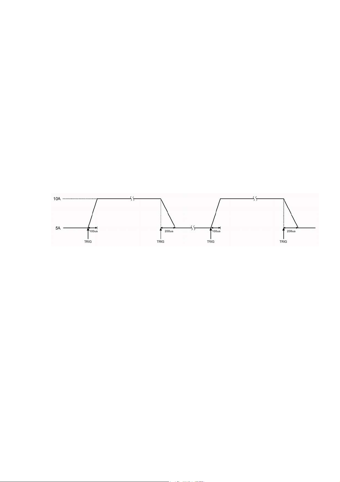
Get the trigger by receiving an external trigger signal. Figure 2-8 shows the current waveform of
the load before it is triggered and after it has been triggered respectively: the electronic load starts
operation at the transient low level (5A) when the input is turned on. For the first trigger, the load
current reaches and remains at the high level (10A) after 100us duration of rising edge. When the
second trigger is
received, the load current will reach and remain at the low level (5A) after 200us
duration of falling edge. Each trigger leads to one toggle operation.
Fig. 2-8 Toggled Transient Operation
2.5 Sequence (List) Operation
Besides Transient operation, the electronic load provides more flexible list operation, which can
make the load operate according to the preset sequence and
synchronize with external signal.
The list operation allows you to program a series of sequence steps, and the operation mode, the
load values, the duration time for each step can be set. The sequence operation can be executed in the
CC, CV, and CR modes. The minimum duration for each step is 10us, and the maximum one is
99999.99999s (around 27.78 hours). The list operation allows to be executed cyclically, and the cycle
times can be set; the different list can be chained so that when one list has been executed, the another
chained list will be enabled, which further perfects the capability of the list test to implement more
complicated test task. Each list can contain 50 steps at most, and the load can store 7 lists.
The associated parameters of list operation can be edited and set through list operation menu or
via remote command. The load provides convenient list editing function. When the user is operating
input/edit sequence step, it is easy to check the previous and subsequent steps, and it is allowed to be
edited, inserted, and deleted immediately, which simplifies the list input operation effectively.
The set value of each step will be automatically saved when exiting from step edit menu, and the
other list parameters will be saved immediately after been edited.
The list operation also can be implemented via the remote command.
Please make sure the transient operation has been disabled before enabling list operation. In list
21
operation, if the operation mode for next step is different from the present step, the load will
automatically have a 5ms delay after the present step is over to avoid the probable current surge. The
load` s input will be turned off during this 5ms-delay.
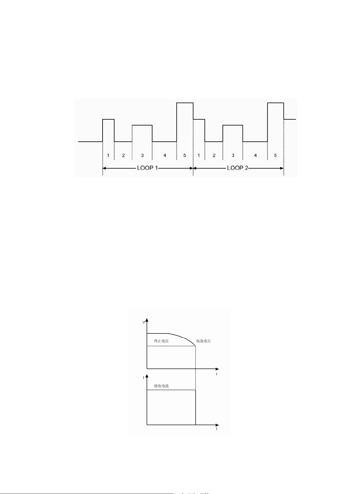
Figure 2-9 is a list running diagram for 5 steps. See chapter 5 for detailed information about
programming lists from the front panel
.
Fig. 2-9 List Operation
Note: In list operation, the Von point and current limit level should be taken into consideration,
which may cause the shut down of the input, so that the list operation is interrupted.
2.6 Battery Discharge Operation
The electronic load adopts constant current discharge to test battery capacity. The discharge
current and termination voltage can be self-defined. When the battery voltage decreases to the
termination voltage, the battery discharge test will be stopped automatically. The test procedure is
shown as figure 2-10. The load can real-time display battery voltage, discharge current, discharge time,
and discharge capacity during the test. The maximum battery discharge time is 99hours 99minutes 99
seconds, and the maximum battery capacity is 4000AH.
Fig. 2-10 Voltage/Current Curve Chart in Battery Discharge Operation

22
2.7 Short Circuit Operation
The electronic load can simulate a short circuit to test the protection performance of the tested
device. The short circuit operation can be enabled and disabled by setting in the main menu, or via the
remote command (INPut:SHORt ON/OFF). When the short circuit operation is enabled, the relevant
short-circuit value depends on the present mode of the load: CCL, the short-circuit current is 4.4A;
CCH, the short-circuit current is 44A; CV, the short-circuit voltage is 0V; CRL, the short-circuit
resistance is 1.8Ω; CRH, the short-circuit resistance is 18Ω; CPV, the short-circuit power is 420W;
CPC, the short-circuit power is 0W.
The other set values will not be changed when the short circuit operation is enabled.
Note: in short circuit operation, the Von point and current limit level should be taken into
consideration, which may cause the shut down of the input, so that the short circuit operation is
interrupted.
2.8 Triggered Operation
The triggered operation is mainly used to make the load keep synchronized with other test
equipments or events. Array 372x series electronic load provides various triggering modes, which can
be applied to the following occasions:
z Triggering a preset level
Transfers all pending preset levels to the immediate levels. For the presently active mode, the new
level will appear at the input at once if the input is turned on. For the modes which are not
presently active, the preset levels will not take effect at the input until the corresponding mode
becomes active.
z Triggering a transient pulse
Gernerates a transient pulse in accordance with the preset transient parameters, when pulsed
transient operation is active.
z Triggering a transient toggle
Switches the input between the transient low level and transient high level in accordance with the
preset transient parameters, when the toggled transient operation is active.
z Triggering a list test
Enables the present list test when the list operation is active.
Three triggering methods are available for remote control: GPIB <GET> signal, the *TRG and
TRIGger commands. The External trigger input terminal and key on the front panel of the load
can be used to trigger(can
generates a trigger signal to the electronic load).
The load has three triggering modes: BUS, EXTernal, and HOLD.
z The BUS mode: the trigger source is GPIB <GET> signal, or *TRG command.
z The EXTernal mode: Choose the External trigger input terminal or
key on the front
panel as the trigger source. The input signal at the External trigger input terminal is TTL, the

23
falling edge (signal) is triggered(can generates a trigger signal to the electronic load)..
z The HOLD mode: Use the command TRIGger:IMMediate as the trigger source. At this
time, all other triggering methods including *TRG become invalid.
Note: The command TRIGger:IMMediate can be used in all three triggering modes. The
triggering modes can be selected via the remote command only (TRIGger:SOURce BUS;
TRIGger:SOURce EXTernal; TRIGger:SOURce HOLD).
2.9 Input Control
2.9.1 Turn On/Off the Load
The input can be turned on/off by pressing
key, or via the remote command (INPUT
ON/OFF).
Turning the input off (zero current) does not affect the programmed settings.
In local control, if the input is turned on, the load status can not be switched directly among the
basic modes, transient operation, list operation and battery discharge operation etc.. The load can be
switched from one operation status to another operation status only when the input is turned off.
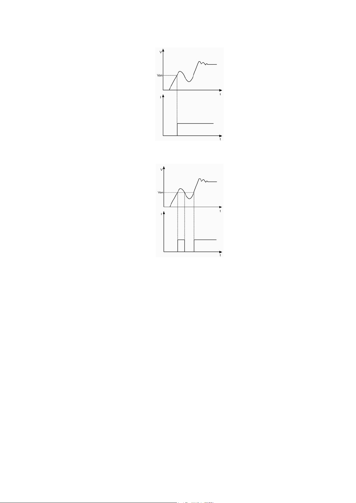
2.9.2 Von Point/Von Latch
When the external input voltage is less than the Von Point, the load will not be enabled even
though the input has been turned on. The load will be enabled till the external input voltage reaches or
exceeds the Von Point.
Von Latch is used to latch the active status of the load. If the Von Latch function is enabled, once
the input voltage reaches Von Point, the input will be turned on, and stay in ON status regardless of the
changes from the external input voltage, even though the input voltage is less than the Von point.
Please see figure 2-11;if the Von Latch function is disabled, once the input voltage reaches Von Point,
the input will be turned on automatically, and once the input voltage is less than the Von Point, the
input will be automatically turned off. Please see figure 2-12. The automatically turning on /off of the
input can be implemented via setting the Von Point and Von Latch, which simplifies test operation
greatly.
The Von Voltage can be set in main menu, or via the remote command (INPut:VOLTage:ON
<NRf+>).
The Von Latch can be set in main menu, or via the remote command
(INPut:VOLTage:ON:LATCh ON/OFF).
24
Fig. 2-11 Von Latch Is Enabled
Fig. 2-12 Von Latch Is Disabled
Note: If the load is unable to operate normally, please check the setting of Von Point.
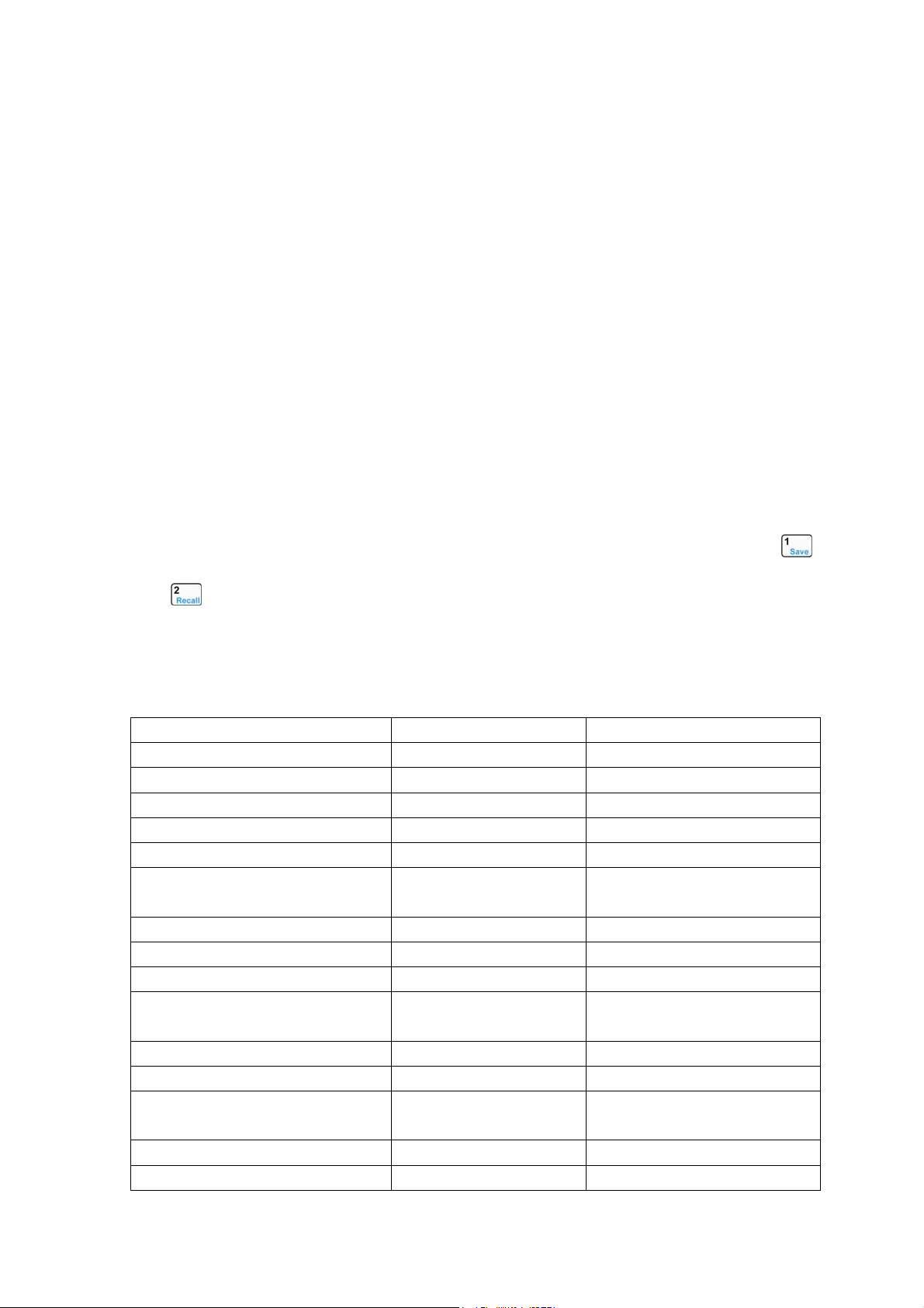
2.9.3 Current Limit in CV Mode
The CV Curr Limit is used to limit the maximum input current in CV mode. If the voltage is still
larger than the set level while the current limit has been reached, the load will switch to the CC mode.
Please see figure 2-13. The input will not be turned off in the CV current limit, which is different from
the software current limit.
The CV Curr Limit can be set in main menu, or via the remote command (CV:CURRent:LIMIt
<NRf+>).
25
Fig.2-13 CV Curr Limit
2.9.4 Current Rise Rate
The Current Rise Rate is used to set the current rise rate in CC mode. It can be set in main menu,
or via the remote command (CURRent:RISE:RATE <NRf+>).
If the current rise rate is 0.1A/us, and the current set level is 20A, then the current rise rate is
shown as below when the input is turned on:
Fig.2-14 Current Rise Rate
Note: The Current Rise Rate can be effective only in CCH and CCL, and the set level is 10 times
larger than the actual current rise rate in CCL.
2.9.5 Current Fall Rate
The Current Fall Rate is used to set the current fall rate in CC mode. It can be set in main menu,
or via the remote command (CURRent:FALL:RATE <NRf+>).
If the current fall rate is 0.1A/us, and the current set level is 20A, then the current rise rate is
shown as below when the input is turned off:
26
Fig.2-15 Current Fall Rate
Note: The Curr Fall Rate can be effective only in CCH and CCL mode, and the set level is 10
times larger than the actual current fall rate in CCL.
2.10 Measurement Function
The electronic load has measurement system with high resolution. The input current level and
voltage level can be measured in real time. The input power level and resistance level can be
computed with the input voltage level and current level. Each measured value can be checked
through LCD display or via the command (MEASure).
2.112.11 Saving and Recalling
The electronic load is provided with a EEPROM
memory, which can save various parameters,
such as modes, input status, current, voltage, resistance, transient settings, and limits etc.. 372x Series
electronic load can save 10 groups of parameters. All parameters relevant to saving and recalling
operation are listed in list2-1.
The 10 groups of parameters stored in location 0~9 can be saved and recalled by pressing
and
keys, or via the remote command (*SAV < NRl > and *RCL < NRl >).
The parameter saved in location 0 will be recalled automatically every time when the load is
turned on.
List 2-1
Function Effect Default
Input Input status Off
Mode Operation mode CCH
Current level Immediate current level 0A
Current rise rate Current rise rate 4A/us
Current fall rate Current fall rate 4A/us
Current Hlevel Transient current high
level
0A
Current Llevel Transient current low level 0A
*Current protection level Current limit 40A
*Current protection delay Current protection delay 60s
*Current protection State Enable/disable current
protection
off
Voltage level Immediate voltage level 80v
CV current limit Current limit in CV mode 40A
Voltage Hlevel Transient high voltage
level
80v
Voltage Llevel Transient voltage low level 80v
Resistance level Immediate resistance level 2000Ω

27
Resistance Hlevel Transient high resistance
high level
2000Ω
Resistance Llevel Transient resistance low
level
2000Ω
Power level Immediate power level 0W
Transient operation Transient test off
Transient mode Transient mode continuous
Transient Htime Time for transient high
level
0ms
Transient Ltime Time for transient low
level
0ms
Transient Rtime Time for transient rising
edge
0.01ms
Transient Ftime Time for transient falling
edge
0.01ms
Trigger Function Trigger function selection Tran
*Trigger source Trigger source external
Battery Mode Battery discharge
operation
off
Battery mini voltage Battery minimum
termination voltage
0V
Battery discharge current Battery discharge current 0A
Voltage on Von point for the load 0V
Voltage on Latch Latch the Von point Off
* indicates it only can be programmed in the remote control.
2.12 Reading Remote Programming Errors
The Err annunciator will be turned on when remote programming errors occur. The error codes
are shown as followings:
z -lxx Command errors
z -2xx Execution errors
z -3xx Device-specific errors
z -4xx Query errors
Remote programming errors can be checked by pressing
key after pressing key on the
front panel. The remote command (SYSTem:ERRor?) can
reads back the error codes and error
messages when it is in remote control.
All errors are saved in one error queue. The errors in this error queue are read in the order in
which they occurred. At most 20 error messages can be saved in the error queue. If the occurred
errors exceed 20, the last error in the error queue will be replaced with -350, “Too many errors”. The
load will not save any additional error message, unless you clear or read errors from the queue. Once
the error message is read, it will be cleared in the error queue.
2.13 Status Report

28
The electronic load incorporates a status reporting register. Various status conditions of the load
can be reported querying the status register. The user can make sure which event has been reported
through setting the enable register (It will be introduced in details in "ARRAY 372x Series Electronic
Load SCPI Programming Guide".).
2.14 Protection Function
The electronic load is equipped with the following protection functions:
z Overvoltage(OV)
z Overcurrent(OC)
z Overpower(OP)
z Overtemperature(OT)
z Reverse Voltage(RV)
Once any of the above protection function is active, the corresponding status bit in the status will
be set; the input will be turned off with beeps; the detected conditions will be displayed; the load will
enter into the latched protection status, and will not respond to other commands except some specific
operations. For example: if an overtemperature conditions has been detected, the input will be turned
off with beeps, and OT will be shown in the lower right corner of the display. The load will have no
response to other operations.
2.14.1 Clearing Latched Protection
When the load enters into the latched protection status, it will have no response to other
commands. The load will return to the normal operation only when the latched protection has been
reset via the secondary function key
or the remote command (INPut:PROTection:CLEar). Of
course, the condition that cause the latched protection must be removed, or it will be latched again as
soon as it is reset.
In addition, when the software overcurrent protection is enabled, if the overcurrent time does not
exceed the specified protection time, the load will display PT to indicate, but the input will not be
turned off. At this time, you can reset the overcurrent time with the secondary function key
or
the remote command (INPut:PROTection:CLEar).
2.14.2 Overvoltage
The overvoltage protection level is set at a predetermined voltage, which cannot be changed by
the user. When the input voltage exceeds this predetermined voltage, the overvoltage protection will be
enabled, and the input is turned off with OV displayed, meanwhile, the OV and VF status register bits
are set, and will remain set until they are reset and overvoltage condition is removed.
2.14.3 Overcurrent
The electronic load allows the user to define a current protection limit. When the defined current
limit is exceeded, the overcurrent timer starts timing, and the display will show PT to indicate
protection status, but the input will not be turned off immediately. When the specified delay time is
reached, the overcurrent protection will be enabled and the input is turned off with OC displayed,

29
meanwhile, the OC and PS status register bits are set, and will remain set until they are reset and
overcurrent condition is removed. The current protection limit function can only be set via the remote
command. It is turned on/off with the command (CURRent:PROTection:STATe ON/OFF). The current
limit level is set with the command (CURRent:PROTection < NRf+>) The specified delay time to turn
off the input can be set with the command (CURRent:PROTection:DELay < NRf+>).
2.14.4 Overpower
The electronic load includes both hardware and software overpower protection functions.
Once the input power exceeds the maximum rated power, the hardware power-limit circuit will be
enabled immediately to limit the input power within the allowed range, in the meantime, the load will
compute the present actual power.
No matter the hardware power-limit circuit is enabled, or use software to compute, the overpower
protection will become active as long as the overpower time exceeds the specified limit. When the
overpower protection is enabled, the input will be turned off with OP displayed, meanwhile, the OP
and PS status register bits are set, and will remain set until they are reset and overpower condition is
removed.
2.14.5 Overtemperature
If the internal temperature of the load exceeds safe limits, the overtemperature protection will be
enabled; the input will be turned off with OT displayed, in the meantime, the OT and PS status register
bits are set, and will remain set until they are reset and overtemperature condition is removed. You
must wait until the load cools down to the normal temperature before you can reset the latched
protection. The fans in the load will help to cool the load as quickly as possible.
2.14.6 Reverse Voltage
When reverse voltage is applied, the reverse voltage protection will be enabled; the input will be
turned off with RV displayed, in the meantime, the RV and VF status register bits are set, and will
remain set until they are reset and reverse voltage is removed.
2.15 Auxiliary Functions
2.15.1Trigger Function Selection
The Trigger Function in main menu is used to select the trigger object. Selecting “Tran” is used to
trigger transient operation, and selecting List is used to trigger sequence (list) operation.
2.15.2 Knob Function
The Knob in main menu is used to enable/disable the knob function. Select On to enable the knob
function, and select Off to disable.
2.15.3 Key Sound
The Key Sound in main menu is used to control the key sound. Select On to activate the key
sound and select Off to forbid.

30
Chapter3 Installation
3.1 Initial Check
When you receive the load, please check it for any obvious damage that may have
occurred during shipment. Keep the original packing materials in case the load has to be
returned to ARRAY in the future.
Please confirm that there are no broken keys or knobs, that the cabinet and panel
surfaces are free of dents and scratches, and that the display is not scratched or cracked.
3.2 Environment/Installation Location
The load can operate at its full power within the temperature range of 0 °C to 40 °C, and
at derated power from 40 °C to 55 °C, or the overtemperature protection will be caused.
Place the load in a location with good ventilation, and keep a distance from
electromagnetic interference. Do not place the load in the flammable atmosphere.
Your load must be installed in a location that allows sufficient space at the sides and rear
of the load for adequate air circulation. The fans cool the load by drawing in air through the
sides and exhausting it out the back. The rubber bumpers must be removed for rack
mounting.
3.3 Power-On/ Self-Test
A power-on self-test can inspect the basic operations of the load to assure you that the
load is operational.
First, check AC power-line voltage to verify the power-line voltage selected by 110V/220V
Toggle Key on the rear panel is in accordance with the proper voltage in your local place.
Connect the power-line cord and a power-on self-test occurs automatically when you turn
on the load. If the load detects an error during power-on self-test, the error messages will be
displayed as they are shown below:
Error
Codes
Error Messages
601 LCD self-test error
603 System ADC test failed
607 Rundown too noisy
608 Keypad self-test error
609 EEPROM checksum failed
630 Temperature test failed
If there is no error is detected, the LCD will show CCH, the initial display, and the input will
be turned off. If the parameters was modified previously and saved in location 0, the load will
recall these modified parameters automatically. After around 20 minutes` warm-up of the load,
the following test can be executed:
Connect the output of a power supply to the load` s input with correct polarity to execute
CCH 5A and CV 5V operations. If the load works normally, it will draw 5A or set input voltage
to 5V within the allowed tolerance.
31
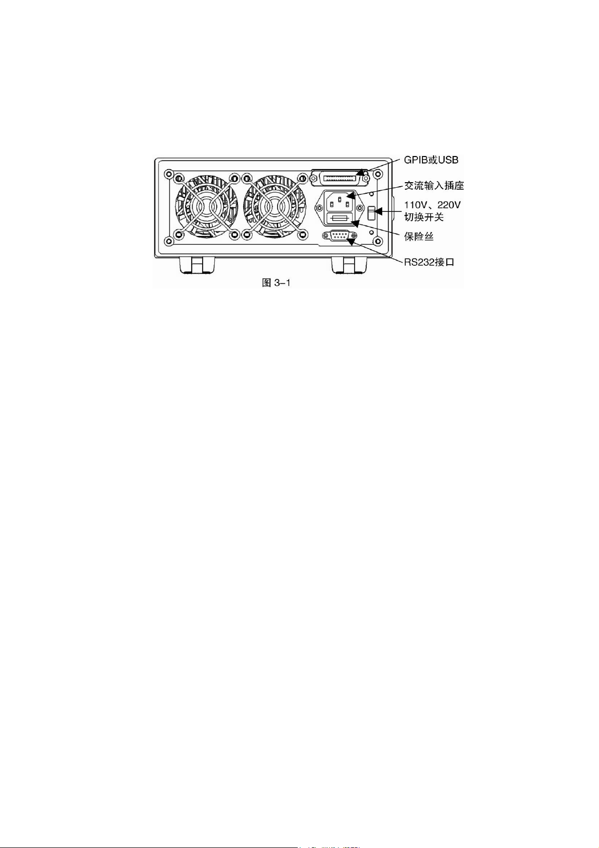
3.4 Connections on the Rear Panel
The rear panel is shown as fig. 3-1, which mainly includes AC input part and
communication interface part. The AC input part includes AC input socket, Fuse holder, and
Line voltage switch; the interface part includes RS-232 interface and the interface for optional
GPIB or USB.
AC input:
AC power-line cord must be appropriate for your local standard.
The specifications of the fuse: 250V 315mA.
Line voltage switch can switch the voltage from 110V to 220V. The selected voltage
should be in accordance with the proper voltage in your local place.
Communication Interfaces:
RS-232 Interface:
The load provides a RS-232 interface, which is a standard DB9 pin connector using DTR
and DSR to execute flow control. The pin assignment is shown below:
Pin Input/Output Description
1 - Not used
2 Input RXD Receive data
3 Output TXD Transmit data
4 Output DTR Data terminal ready
5 Common GND Ground
6 Input DSR Data set ready
7 - Not used
8 - Not used
9 - Not used
The interface parameters can be set in the MENU, you can use SCPI language for
programming to realize the communication with the load.
GPIB Interface:
The load provides a GPIB interface, and you can set its address to any value between 0
and 30 in MENU. When multiple GPIB devices are connected, each device on the GPIB
interface must have a unique address that is not be used by the devices on other interfaces.
The address is set to “05” when the load is shipped from the factory. The default setting can
be changed when you are setting the interface.
32
USB Interface:
The load provides a USB interface. You need to install the software provided by the
factory in PC to realize communication with the load.
USB and GPIB interfaces occupy the same expansion slot on the rear panel, so only one
type interface can be chosen to install at the same time, meanwhile, only one type interface
can be used by the load to communicate with external devices.
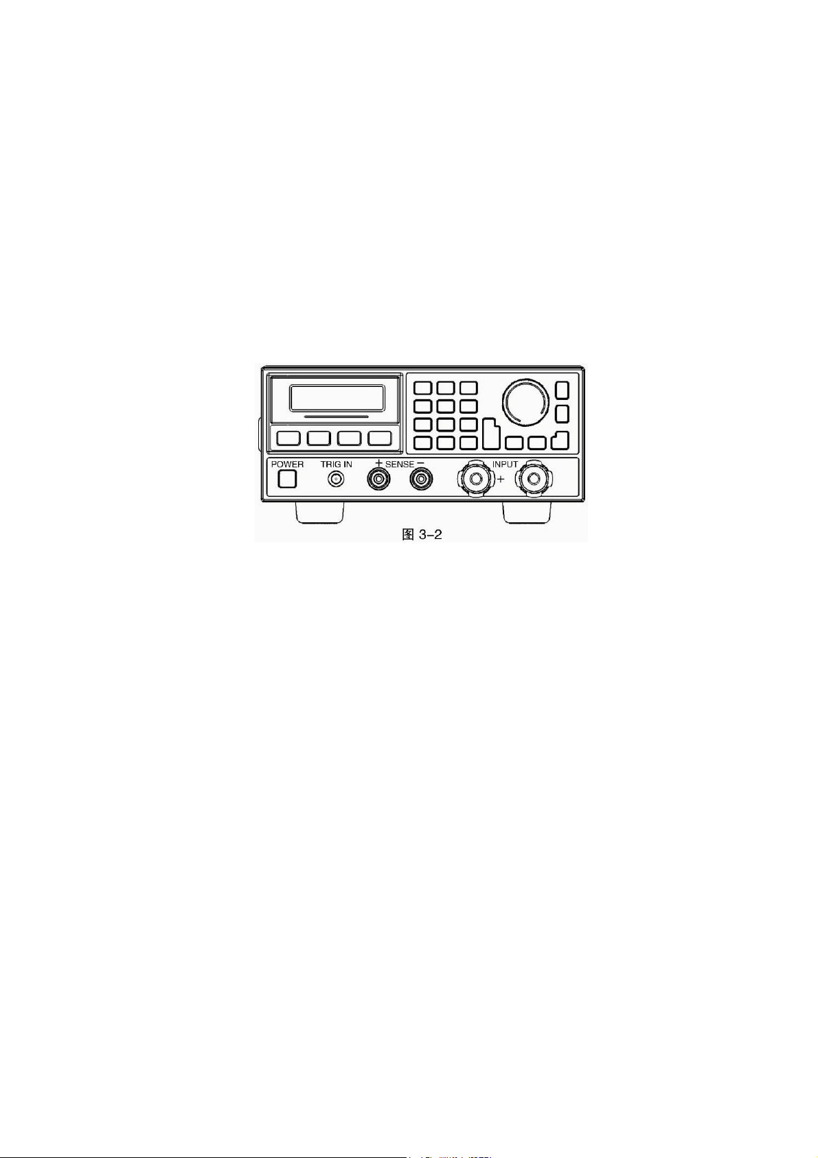
3.5 Connections on the Front Panel
The terminals on the front panel include input terminals (INPUT+, INPUT-), remote sense
terminals (SENSE +, SENSE -), and an external trigger input terminal. See Fig. 3-2.
Input Connections
Input connections are made to two binding posts (INPUT+, INPUT-) on the front panel.
The maximum wire diameter is 6mm. In order to enhance the test accuracy, and reduce the
test error when executing large current test, it would be better to use thicker wire.
Remote Sense
Remote sensing is made to two terminals (SENSE+, and SENSE-). It compensates for
the voltage drop caused by the power supply and input wire resistance to achieve greater
accuracy.
The load can detect voltage inputs automatically, so there is no need to modify the
parameter settings or change the hardware wiring when using remote sensing.
TRIGGER Connections
The external trigger input terminal on the front panel is a BNC connector, in which the
middle part is the input+, and the outer casing is the input-. It receives 5V TTL-compatible
falling-edge trigger signals.
3.6 Wiring
Sense Connections
When greater accuracy of voltage test is needed, it is necessary to connect Sense input,
and the load will switch to Sense status automatically. The relevant wiring is shown as fig.3-3.
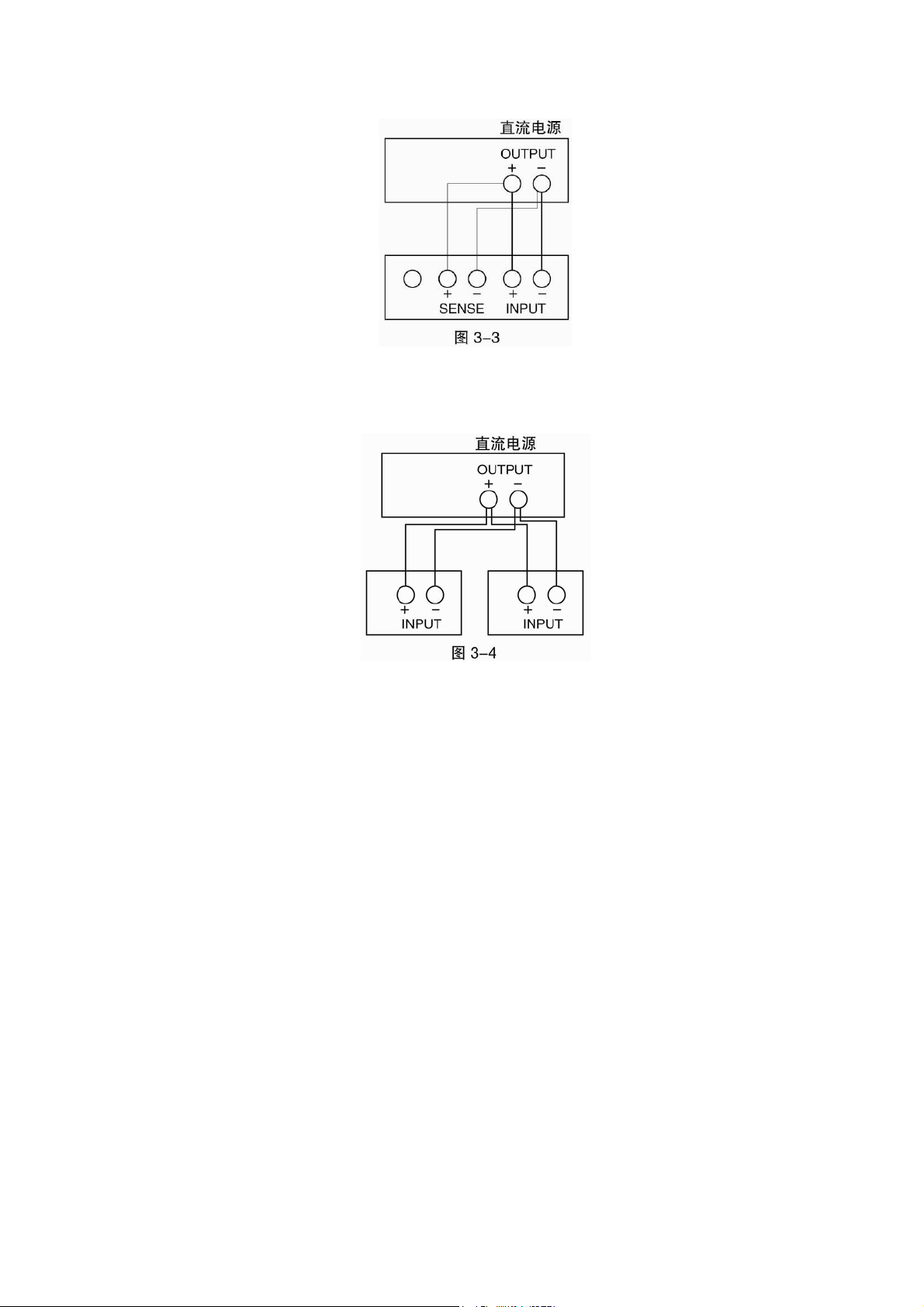
33
Parallel Connections
Figure 3-4 illustrates how two or more loads can be paralleled in CC or CR mode when
high power or large current is needed.

34
Chapter 4 Local Operation
The local operation of the load has been briefly introduced in Chapter2 Functions and Features. In
this chapter, it will be explained in details with examples.
4.1 Local Control
If you need to control the load via operations on the front panel, the load must stay in the local
control status. The load enters into local control status once it is powered on, and preset parameters
saved in EEPROM location 0 will be recalled automatically.
Under remote control status, all operations on front panel keypad and knobs become invalid
(except
, keys). When the load receives a remote command (SYST:REM) via RS232 or GPIB,
the remote control goes into effect and REM annunciator is turned on.
Under remote control status, all operations on electronic load are controlled by remote controller.
The electronic load will return to local control after receiving the return command (e.g. : SYST:LOC).
Or you can return the electronic load to local control by pressing
and keys.
4.2 Main Operation on the Front Panel
z Connecting to the Power Supply
z Turning the Input On/Off
z CC Mode
z CV Mode
z CR Mode
z CP Mode
z Short Circuit Operation
z Continuous Transient Operation
z Pulsed Transient Operation
z Toggled Transient Operation
z Sequence (List) Operation
z Battery Discharge Operation
z Saving and Recalling Parameters
z Clear Protection Settings
z Error Messages
z Triggered Operation
z Main Menu
4.3 Connecting to the Power Supply
Connect the positive pole of the power supply to the INPUT + terminal, and connect the negative
pole of the power supply to the INPUT - terminal. If the input is connected reversely, the RV
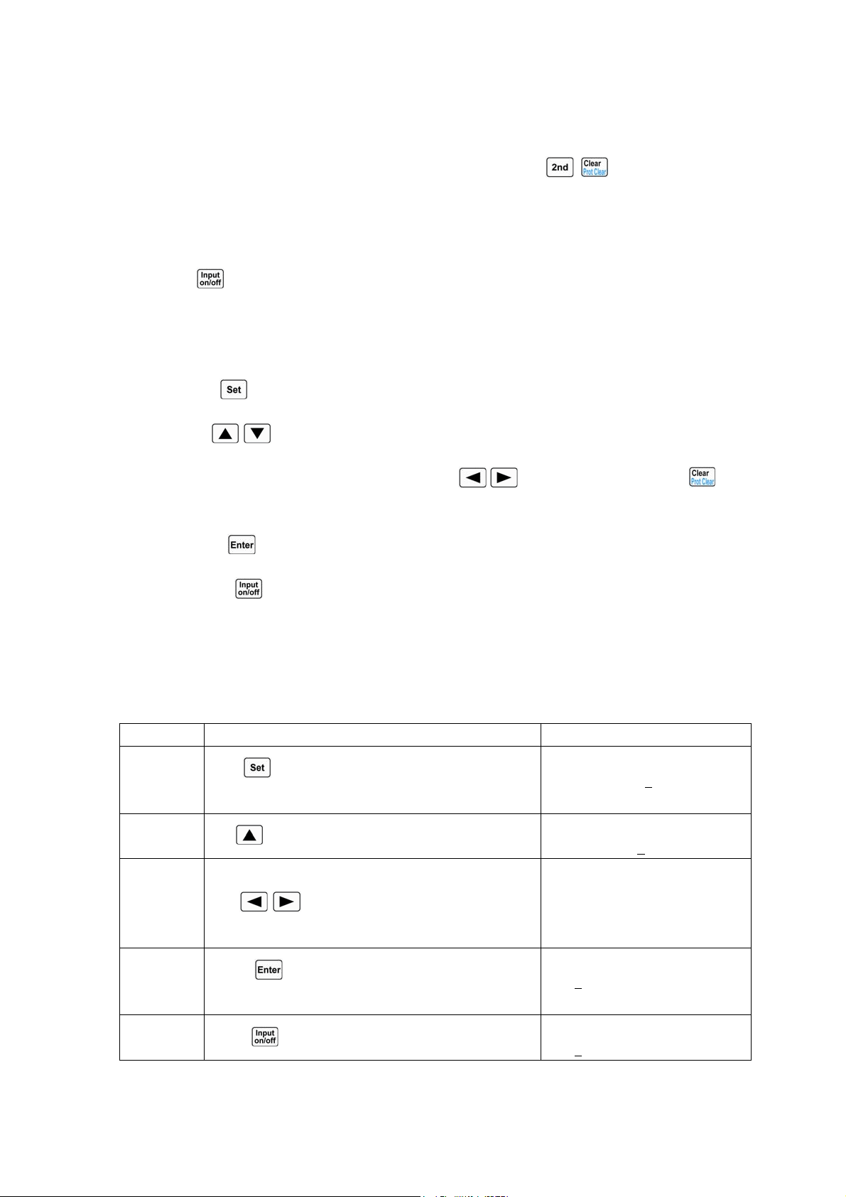
35
protection status of the load will become effective, and please try to connect the power supply to the
load again at this time.
After the power supply is correctly connected to the load, press
+ keys to clear the RV
protection status (the relevant details will be described in “Clearing Protection Settings”).
4.4 Turning the Input On/Off
Press key to turn on or turn off the input.
4.5 Basic Tests
The operating procedures for basic tests are shown below:
1. Press
key to enter into the mode selection and parameter setting menu.
2. Use
, keys to select one basic mode.
3. Use Entry keys or use the knob together with
, keys to input set value. Use key
to modify the set value or exit the mode selection and parameter setting menu.
4. Press
key to confirm and exit the mode selection and parameter setting menu.
5. Press key to turn on the load.
4.5.1 CC Mode
CC Mode includes constant current high range (CCH) and constant current low range (CCL).
Example1: Set the load to CCH and set the current value to 5.12A in CV mode.
Turn on the load, and check the present power value. The operating procedures are
shown below:
Procedures Operation Descriptions Display
1
Press
key to enter into the mode selection and
parameter setting menu;
MODE:CV
CURR: 80.000
A
2
Use
key to select CCH;
MODE:CCH
CURR: 0.000
A
3 Use Entry keys or use the knob together
with , keys to input the current value to
5.12;
MODE:CCH
CURR: 5.120A
4
Press key to confirm and exit the mode
selection and parameter setting menu;
0.000V 0.000A
5.120
A CCH OFF
5
Press
key to turn on the load;
0.000V 0.000A
5.120
A CCH ON
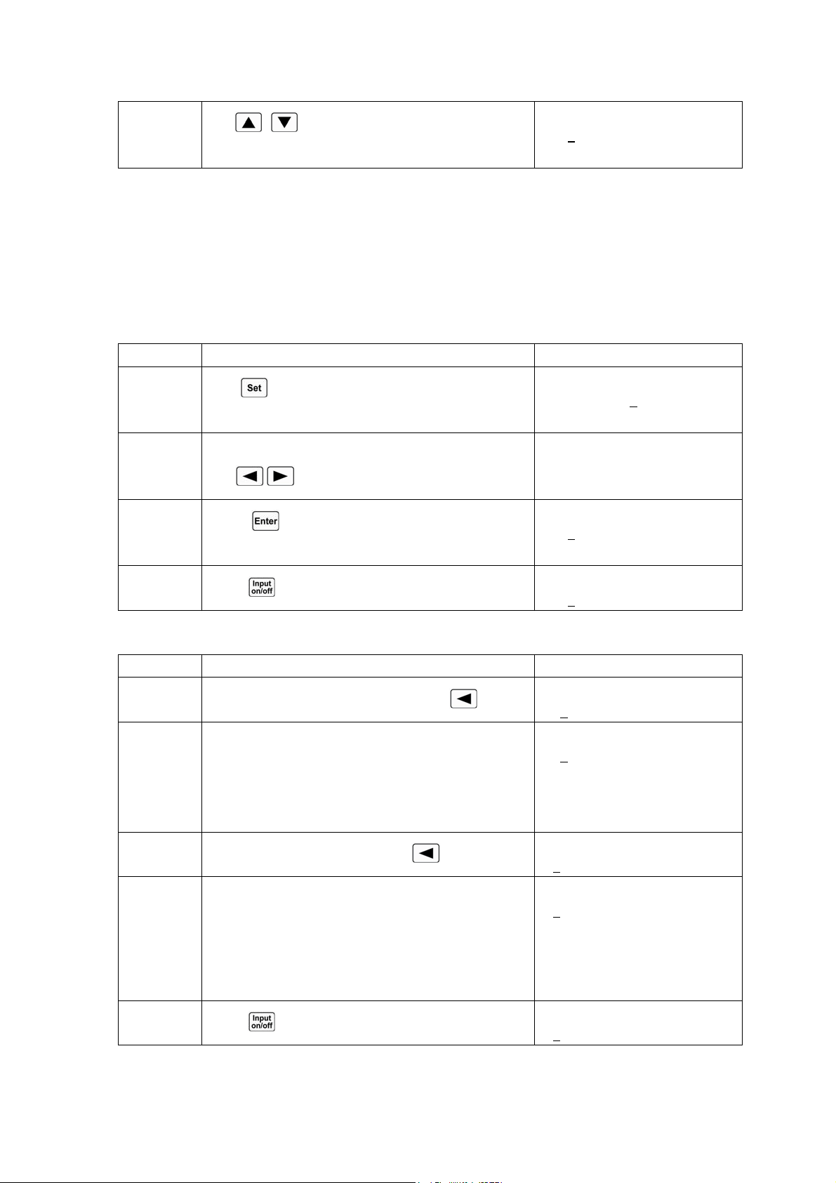
36
6
Use
, keys to check the present power
value;
0.000V 0.000A
5.120
A 0.000W
For the above operating procedures, the corresponding SCPI commands should be:
MODE CCH ;Sets the mode
CURR 5.12 ;Sets the current value
INPUT ON ;Turns on the load
Example2: Set the current value to 5.8A in CCH.
Turn on the load, and there are two ways to set the current value.
Solution 1:
Procedures Operation Descriptions Display
1
Press
key to enter into the mode selection and
parameter setting menu;
MODE:CCH
CURR: 5.120
A
2 Use Entry keys or use the knob together
with , keys to input the current value to 5.8;
MODE:CCH
CURR: 5.800A
3
Press key to confirm and exit the mode
selection and parameter setting menu;
0.000V 0.000A
5.800
A CCH OFF
4
Press
key to turn on the load;
0.000V 0.000A
5.800
A CCH ON
Solution2:
Procedures Operation Descriptions Display
1
Move the cursor to the hundredths with
key;
0.000V 0.000A
5.12
0A CCH OFF
2 Rotate the knob to set the hundredths to 0;
(The set value will be changed when rotating the
knob. The set value will become effective at input at
once when the load is turned on.)
0.000V 0.000A
5.10
0A CCH OFF
3
Move the cursor to the tenths with
key;
0.000V 0.000A
5.1
00A CCH OFF
4 Rotate the knob to set the tenths to 8;
(The set value will be changed when rotating the
knob. The set value will become effective at input at
once when the load is turned on.)
0.000V 0.000A
5.8
00A CCH OFF
5
Press
key to turn on the load;
0.000V 0.000A
5.8
00A CCH ON
For the above operating procedures, the corresponding SCPI commands should be:
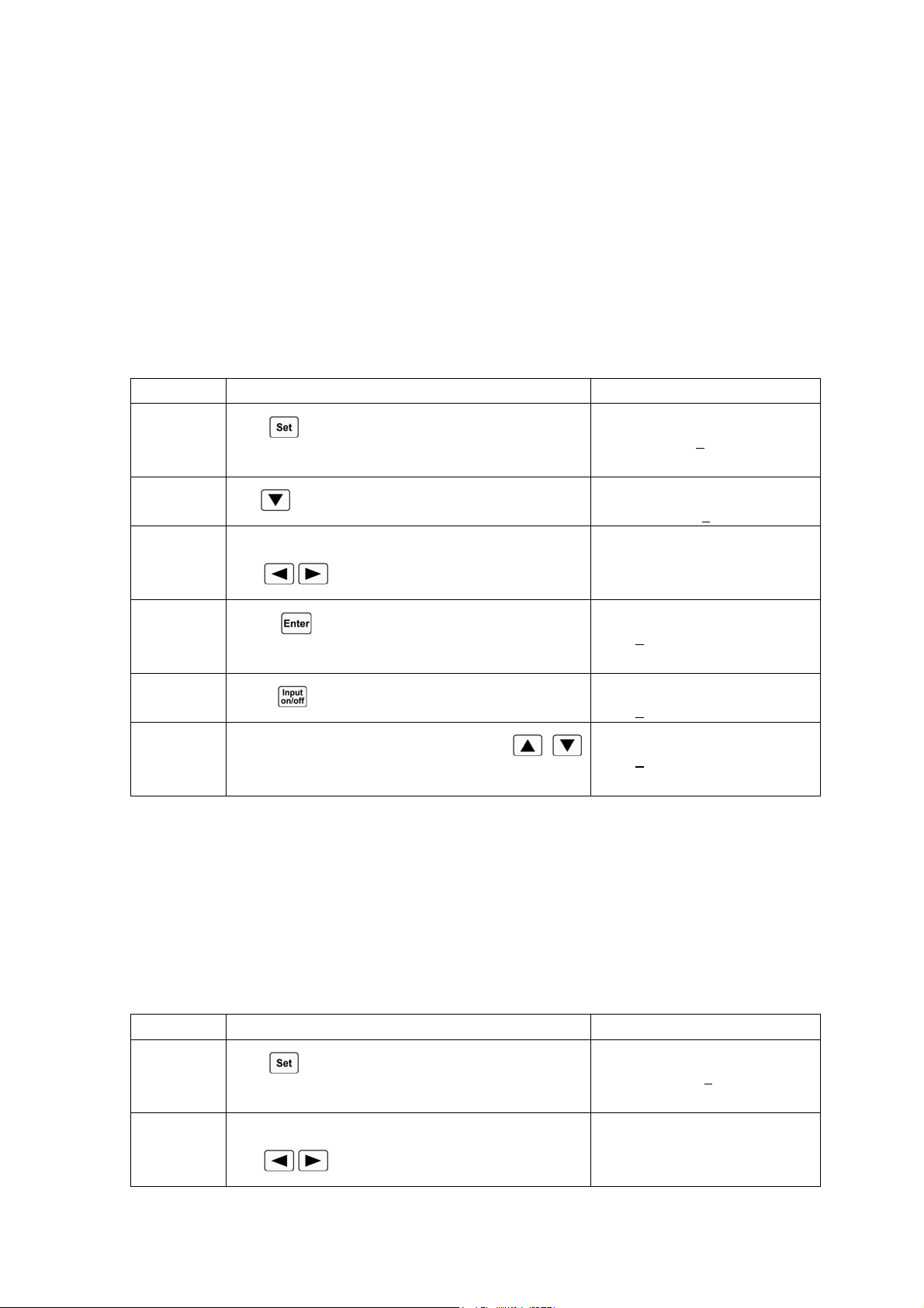
37
MODE CCH ;Sets the mode
CURR 5.8 ;Sets the current value
INPUT ON ;Turns on the load
Note: CCH /CCL will be shown respectively in the lower right corner of the display when the
load is in CCH status or CCL status.
4.5.2 CV Mode
Example1: Set the load to CV mode and the voltage value to 50V in CCH mode.
Turn on the load, and check the present power value. The operating procedures are
shown below:
Procedures Operation Descriptions Display
1
Press
key to enter into the mode selection and
parameter setting menu;
MODE:CCH
CURR: 3.800
A
2
Use
key to select CV mode;
MODE:CV
VOLT: 80.000
V
3 Use Entry keys or use the knob together
with , keys to input the voltage value to 50;
MODE:CV
VOLT: 50.000V
4
Press key to confirm and exit the mode
selection and parameter setting menu;
0.000V 0.000A
50.000
V CV OFF
5
Press
key to turn on the load;
0.000V 0.000A
50.000
V CV ON
6
Check the present power value with
,
keys;
0.000V 0.000A
50.000
V 0.000W
For the above operating procedures, the corresponding SCPI commands should be:
MODE CV ;Sets the mode
VOLT 50 ;Sets the voltage value
INPUT ON ;Turns on the load
Example2: Set the voltage value to 60V in CV mode.
Turn on the load, and there are two ways to set the voltage value.
Solution 1:
Procedures Operation Descriptions Display
1
Press
key to enter into the mode selection and
parameter setting menu;
MODE:CV
CURR: 50.000
V
2 Use Entry keys or use the knob together
with
, keys to input the voltage value to 60;
MODE:CV
VOLT: 60.000V
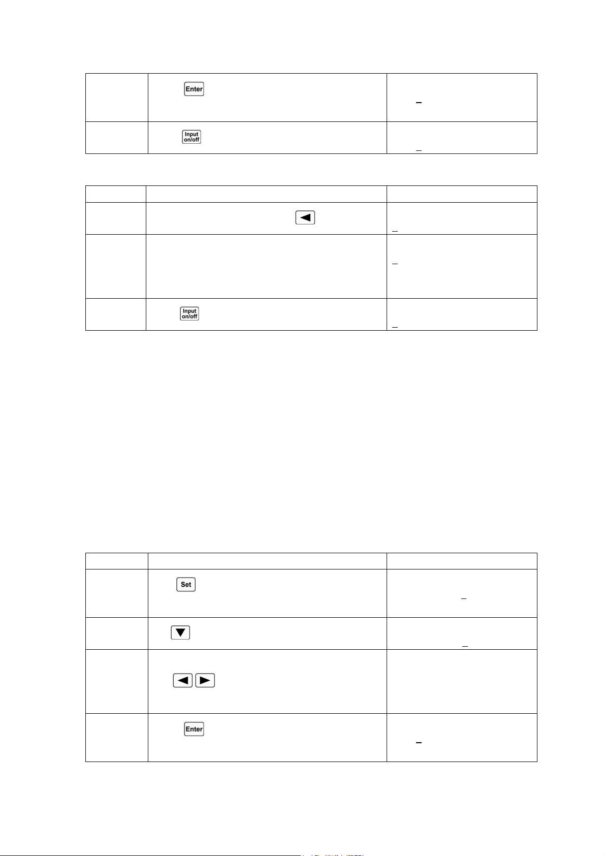
38
3
Press key to confirm and exit the mode
selection and parameter setting menu;
0.000V 0.000A
60.000
V CV OFF
4
Press
key to turn on the load;
0.000V 0.000A
60.000
V CV ON
Solution 2:
Procedures Operation Descriptions Display
1
Move the cursor to the tens with
key;
0.000V 0.000A
5
0.000V CV ON
2 Rotate the knob to set the tens to 6;
(The set value will be changed when rotating the
knob. The set value will become effective at input at
once when the load is turned on.)
0.000V 0.000A
6
0.000V CV OFF
3
Press
key to turn on the load;
0.000V 0.000A
6
0.000V CV ON
For the above operating procedures, the corresponding SCPI commands should be:
MODE CV ;Sets the mode
VOLT 60 ;Sets the voltage value
INPUT ON ;Turns on the load
Note: CV will be shown in the lower right corner of the display when the load is in CV mode.
4.5.3 CR Mode
CR Mode includes constant resistance low range (CRL), constant resistance medium range
(CRM), and constant resistance high range (CRH).
Example1: Set the load to CRL and set the resistance value to1.5Ωin CV mode.
Turn on the load, and check the present power value. The operating procedures are
shown below:
Procedures Operation Descriptions Display
1
Press
key to enter into the mode selection and
parameter setting menu;
MODE:CV
CURR: 50.000
V
2
Use
key to select CRL;
MODE: CRL
RES : 0.0200
Ω
3 Use Entry keys or use the knob together
with , keys to input the resistance value to
1.5;
MODE: CRL
RES : 1.5000Ω
4
Press key to confirm and exit the mode
selection and parameter setting menu;
0.000V 0.000A
1.5000
Ω CRL OFF
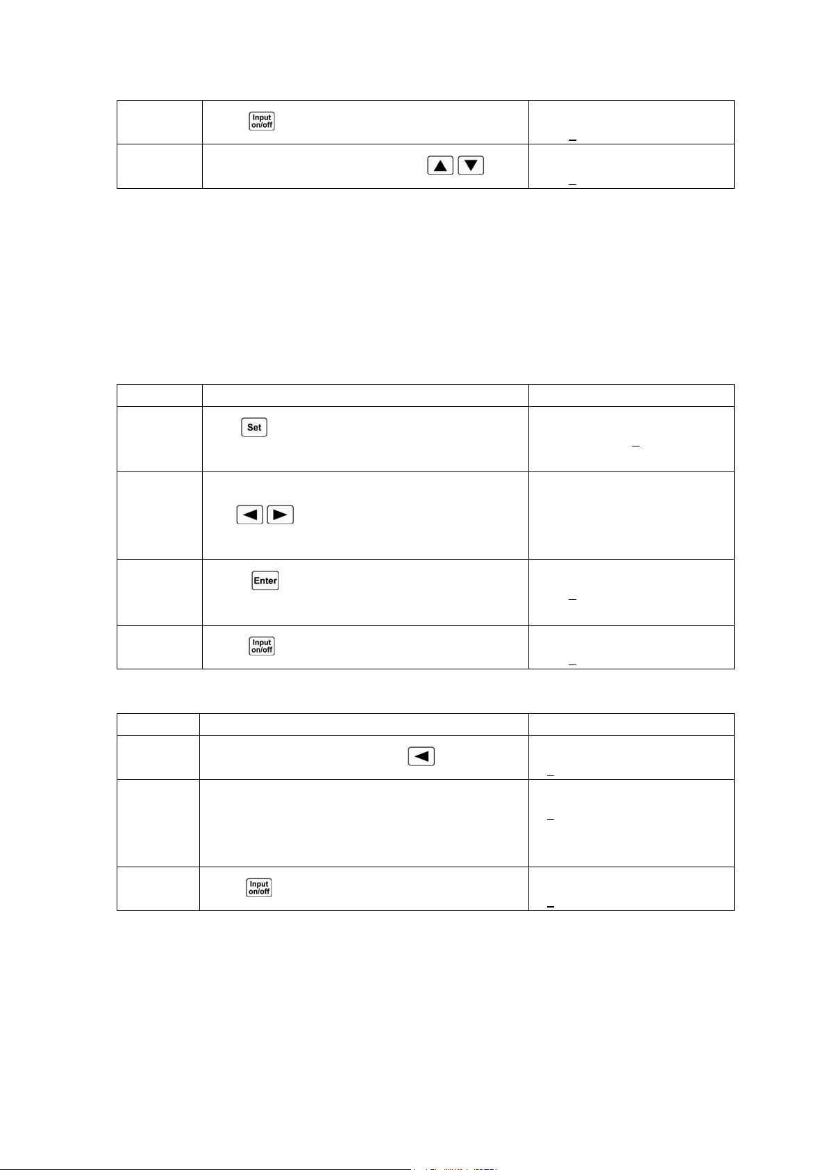
39
5
Press
key to turn on the load;
0.000V 0.000A
1.5000
Ω CRL ON
6
Check the present power value with
, ;
0.000V 0.000A
1.5000
Ω 0.000W
For the above operating procedures, the corresponding SCPI commands should be:
MODE CRL ;Sets the mode
RES 1.5 ;Sets the resistance value
INPUT ON ;Turns on the load
Example2: Set the resistance value to 1.8Ωin CRL.
Turn on the load, and there are two ways to set the resistance value.
Solution 1:
Procedures Operation Descriptions Display
1
Press
key to enter into the mode selection and
parameter setting menu;
MODE: CRL
RES : 1.5000
Ω
2 Use Entry keys or use the knob together
with , keys to input the resistance value to
1.8;
MODE: CRL
RES : 1.8000Ω
3
Press key to confirm and exit the mode
selection and parameter setting menu;
0.000V 0.000A
1.8000
Ω CRL OFF
4
Press
key to turn on the load;
0.000V 0.000A
1.8000
Ω CRL ON
Solution 2:
Procedures Operation Descriptions Display
1
Move the cursor to the tenths with
key;
0.000V 0.000A
1.5
000Ω CRL OFF
2 Rotate the knob to set the tenths to 8;
(The set value will be changed when rotating the
knob. The set value will become effective at input at
once when the load is turned on.)
0.000V 0.000A
1.8
000Ω CRL OFF
3
Press
key to turn on the load;
0.000V 0.000A
1.8
000Ω CRL ON
For the above operating procedures, the corresponding SCPI commands should be:
MODE CRL ;Sets the mode
RES 1.8 ;Sets the resistance value
INPUT ON ;Turns on the load
Note: CRH /CRM/CRL will be shown respectively in the lower right corner of the display when
the load is in CRH status, CRM status or CCL status.
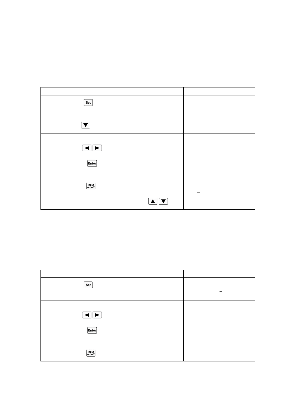
40
4.5.4 CP Mode
CP Mode includes constant power-current source mode (CPV) and constant power-voltage source
mode (CPC).
Example1: Set the load to CPV and set the power value to100W in CRL.
Turn on the load, and check the present power value. The operating procedures are
shown below:
Procedures Operation Descriptions Display
1
Press
key to enter into the mode selection and
parameter setting menu;
MODE: CRL
RES : 1.8000
Ω
2
Use
key to select CPV;
MODE: CPV
POWR: 0.000
W
3 Use Entry keys or use the knob together
with , keys to input the power value to 100;
MODE: CPV
POWR: 100.00W
4
Press key to confirm and exit the mode
selection and parameter setting menu;
0.000V 0.000A
100.00
W CPV OFF
5
Press
key to turn on the load;
0.000V 0.000A
100.00
W CPV ON
6
Check the present power value with
, ;
0.000V 0.000A
100.00
W 0.000W
For the above operating procedures, the corresponding SCPI commands should be:
MODE CPV ;Sets the mode
POW 100 ;Sets the power value
INPUT ON ;Turns on the load
Example2: Set the power value to 200W in CPV mode.
Turn on the load, and there are two ways to set the power value.
Solution 1:
Procedures Operation Descriptions Display
1
Press
key to enter into the mode selection and
parameter setting menu;
MODE: CPV
POWR: 100.00
W
2 Use Entry keys or use the knob together
with , keys to input the power value to 200;
MODE: CPV
POWR: 200.00W
3
Press key to confirm and exit the mode
selection and parameter setting menu;
0.000V 0.000A
200.00
W CPV OFF
4
Press
key to turn on the load;
0.000V 0.000A
200.00
W CPV ON
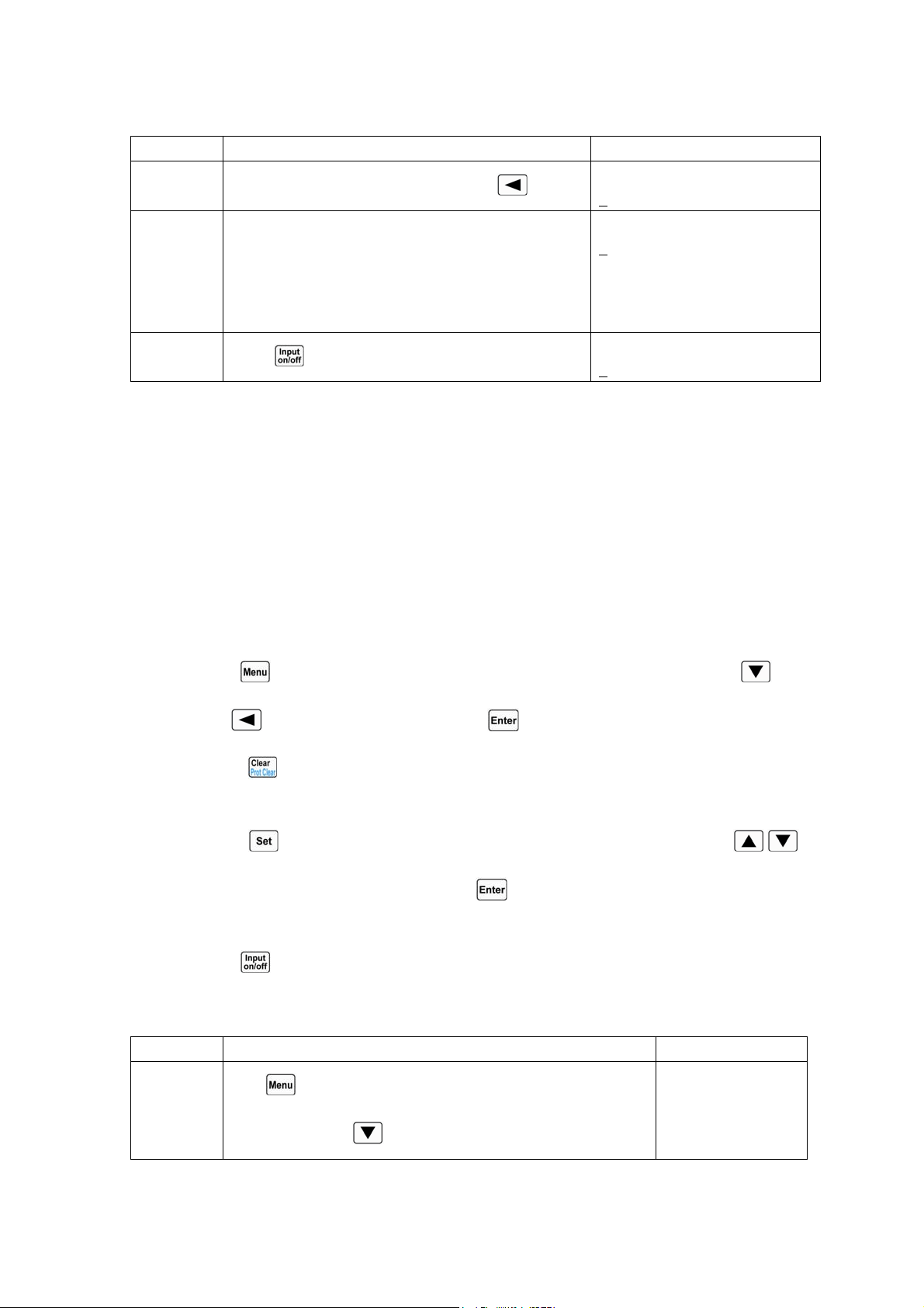
41
Solution 2:
Procedures Operation Descriptions Display
1
Move the cursor to the hundredths with
key;
0.000V 0.000A
1
00.00W CPV OFF
2 Rotate the knob to set the hundredths to 2;
(The set value will be changed when rotating the
knob. The set value will become effective at input at
once when the load is turned on.)
0.000V 0.000A
2
00.00W CPV OFF
3
Press
key to turn on the load;
0.000V 0.000A
2
00.00W CPV ON
For the above operating procedures, the corresponding SCPI commands should be:
MODE CPV ;Sets the mode
POW 200 ;Sets the power value
INPUT ON ;Turns on the load
Note: CPV /CPC will be shown respectively in the lower right corner of the display when the load
is in CPV or CPC mode.
4.6 Short Circuit Operation
The operating procedures for short circuit operation are shown below:
1. Press
key to enter into main menu, and select Short (short circuit) item with key.
2. Use
key or knob to set On, and press key to confirm.
3. Press key to exit the main menu. The display shows “s” to indicate in the basic test
mode.
4. Press
key to enter into the mode selection and parameter setting menu; use ,
keys to select one basic test mode; press
key to confirm and exit the mode selection
and parameter setting menu.
5. Press
key to turn on the load.
Example1: The load was in CV mode previously and it is turned off. Set the load to short circuit
in CCH status. Turn on the load to execute short circuit operation.
Procedures Operation Descriptions Display
1
Press
key to enter into main menu, and select Short (short
circuit) item with
key.
Short:
On *Off
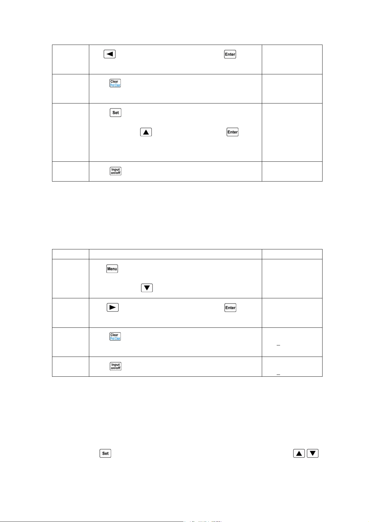
42
2
Use key or knob to set On, and press key to
confirm.
Short:
*On Off
3
Press
key to exit the main menu. The display shows “s”
to indicate in CV mode.
0.000V 0.000A
0.000V sCV OFF
4
Press
key to enter into the mode selection and parameter
setting menu; use
key to select CCH; press key to
confirm and exit the mode selection and parameter setting
menu.
0.000V 0.000A
44.000A sCCH OFF
5
Press
key to turn on the load;
0.000V 0.000A
44.000A sCCH ON
For the above operating procedures, the corresponding SCPI commands should be:
INPUT:SHORT ON ; Sets the load to short circuit operation
MODE CCH ; Sets the mode
INPUT ON ; Turns on the load
Example2: Based on the last example, exit the short circuit operation, and turn off the load.
Procedures Operation Descriptions Display
1
Press
key to enter into main menu, and select Short (short
circuit) item with
key.
Short:
*On Off
2
Use
key or knob to set Off, and press key to
confirm.
Short:
On *Off
3
Press
key to exit the main menu. On the display, “s”
disappears in CCH status.
0.000V 0.000A
0.000
A CCH ON
4
Press
key to turn off the load;
0.000V 0.000A
0.000
A CCH OFF
For the above operating procedures, the corresponding SCPI commands should be:
INPUT:SHORT OFF ;Sets the load to exit the short circuit operation
INPUT OFF ;Turns on the load
4.7 Transient Operation
The operating procedures for transient operation are shown below:
1. Press
key to enter into the mode selection and parameter setting menu; use ,
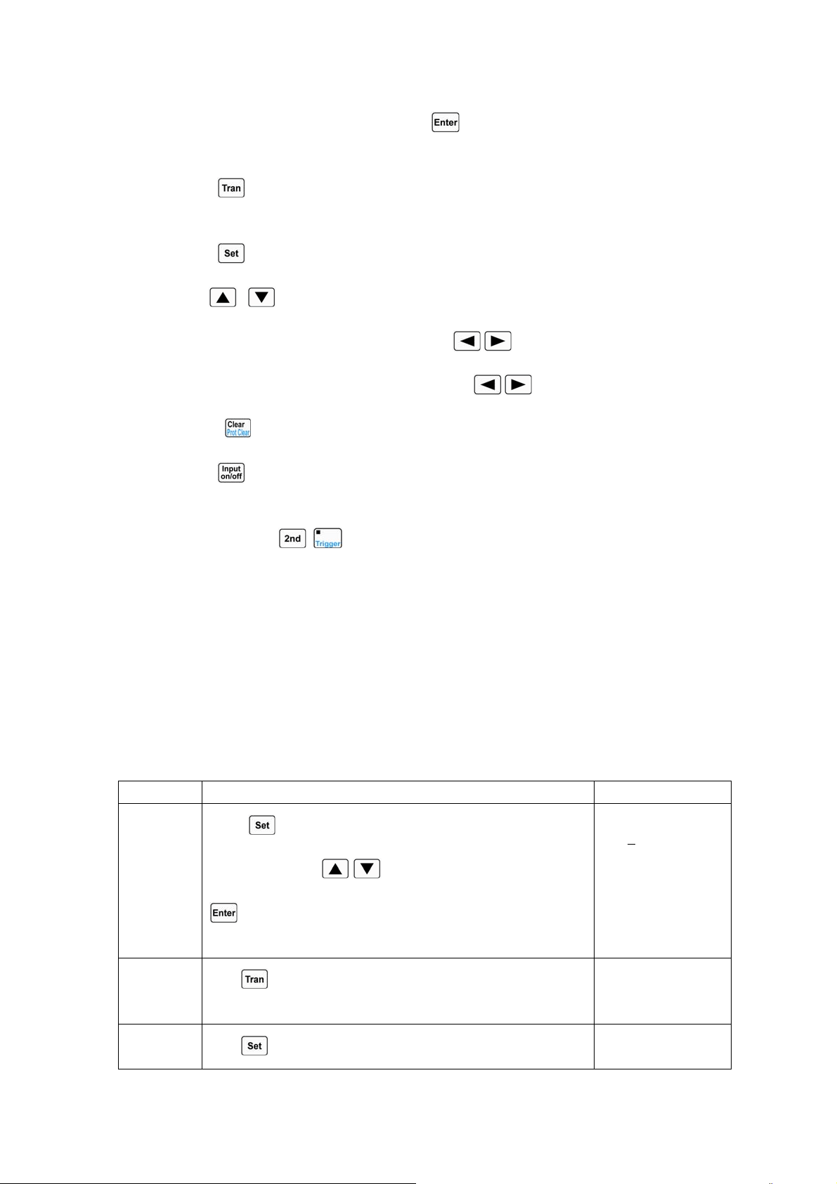
43
keys to select one basic test mode; press key to confirm and exit the mode selection
and parameter setting menu.
2. Press key to enter into transient operation. The display shows “t” to indicate in the
basic test mode.
3. Press key to enter into the transient operation menu.
4. Use , keys to select the parameter.
5. Use Entry keys or use the knob together with , keys to set values for LevelL,
LevelH, TimeL, TimeH, TimeR, and TimeF. Use
, keys or knob to set Mode value.
6. Press key to exit the transient operation menu.
7. Press key to turn on the load.
8. If it is the pulsed transient operation or the toggled transient operation, one trigger occurs
when pressing
+ key or the signal at the trigger input terminal (TRIG IN) is low
level.
4.5.5 Continuous Transient Operation
In continuous operation, the load periodically switches between high/low levels. The relevant
parameters such as low level (LevelL), high level (LevelH), low level time (TimeL), high level time
(TimeH), time for rising edge (TimeR), time for falling edge (TimeF),
Example1: Set the load voltage value to periodically switch between 1V and 5V; set the time for
rising edge (TimeR) to 10ms; set high level time (TimeH) to 200ms; set time for falling edge (TimeF)
to 20ms; set low level time (TimeL) to 400ms, and the load is in continuous transient operation. The
operating procedures are shown as below:
Procedures Operation Descriptions Display
1
Press
key to enter into the mode selection and parameter
setting menu; use
, keys to select CV mode; press
key to confirm and exit the mode selection and parameter
setting menu.
0.000V 0.000A
0.000
V CV OFF
2
Press
key to enter into transient operation. The display
shows “t” to indicate in CV mode.
0.000V 0.000A
80.000V
tCV OFF
3
Press
key to enter into the transient operation menu.
► LevelL:80.000V
LevelH:80.000V
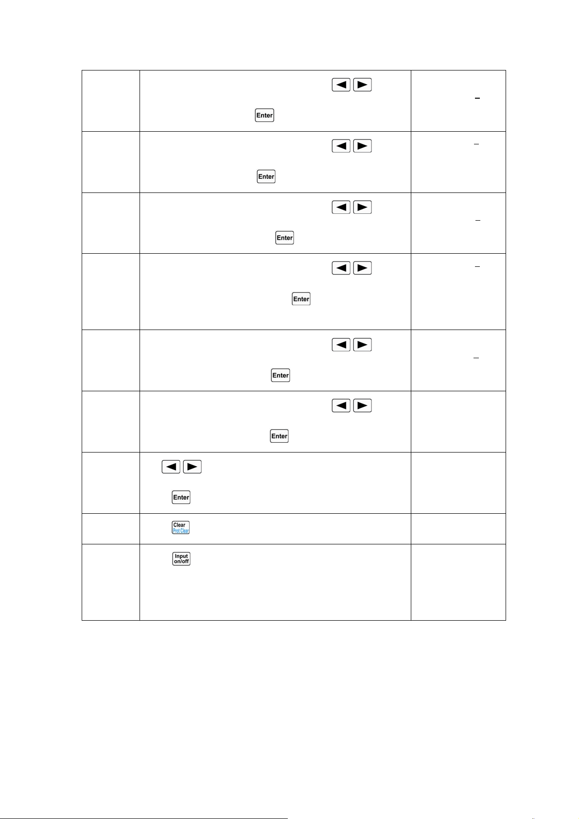
44
4
Use Entry keys or use the knob together with
, keys to
set LevelL to 1, and press
key to confirm.
LevelL:1.000V
►LevelH:80.000V
5
Use Entry keys or use the knob together with
, keys to
set LevelH to 5, and press
key to confirm.
►TimeL :530.00ms
TimeH :500.00ms
6
Use Entry keys or use the knob together with
, keys to
set TimeL to 400ms, and press
key to confirm.
TimeL :400.00ms
►TimeH :500.00ms
7
Use Entry keys or use the knob together with
, keys to
set TimeH to 200ms, and press
key to confirm. The
menu will show the next item automatically.
►TimeR: 100.00ms
TimeF: 100.00ms
8
Use Entry keys or use the knob together with
, keys to
set TimeR to 10ms, and press
key to confirm.
TimeR: 10.00ms
►TimeF: 100.00ms
9
Use Entry keys or use the knob together with
, keys to
set TimeF to 20ms, and press
key to confirm.
►Mode: ◄ Cont ►
10
Use
, keys or knob to set Mode value to Cont, and
press
key to confirm.
►Mode: ◄ Cont ►
11
Press
key to exit the transient operation menu.
0.000V 0.000A
1.000V
tCV OFF
12
Press
key to turn on the load;
0.000V 0.000A
1.000V
tCV ON
0.000V 0.000A
5.000V
tCV ON
For the above operating procedures, the corresponding SCPI commands should be:
MODE CV ;Sets the mode
TRAN ON ;Enables the transient operation
VOLT:LLEV 1 ;Sets a value to low level
VOLT:HLEV 5 ;Sets a value to high level
TRAN:LTIME 400 ms ;Sets a value to low level time
TRAN:HTIME 200ms ;Sets a value to high level time
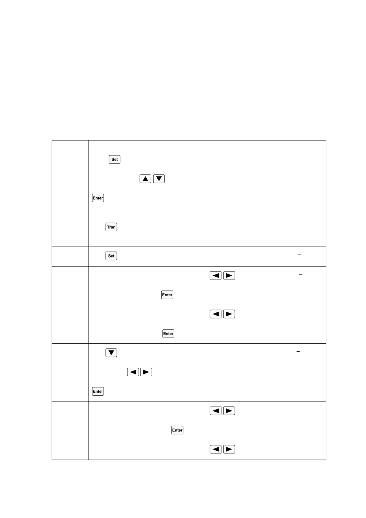
45
TRAN:RTIME 10ms ;Sets a value to time for rising edge
TRAN:FTIMR 20ms ;Sets a value to time for falling edge
TRAN:MODE CONT ;Selects continuous transient operation
INPUT ON ;Turns on the load
4.5.6 Pulsed Transient Operation
Example1: Assume that the load is in external triggering mode, set the load current value to
periodically switch between 1A and 5A; set the time for rising edge (TimeR) to10ms; set high level
time (TimeH) to 200ms; set time for falling edge (TimeF) to 10ms; the load is in pulsed transient
operation, and a trigger occurs at this time.
Procedures Operation Descriptions Display
1
Press
key to enter into the mode selection and parameter
setting menu; use
, keys to select CCH mode; press
key to confirm and exit the mode selection and parameter
setting menu.
0.000V 0.000A
0.000
A CCH OFF
2
Press
key to enter into transient operation. The display
shows “t” to indicate in CCH status.
0.000V 0.000A
0.500A
tCCH OFF
3
Press
key to enter into the transient operation menu.
►LevelL: 0.500A
LevelH:1.000A
4
Use Entry keys or use the knob together with
, keys to
set LevelL to 1, and press
key to confirm.
LevelL: 1.000
A
►LevelH: 1.000A
5
Use Entry keys or use the knob together with
, keys to
set LevelH to 5, and press
key to confirm.
►TimeL:400.00ms
TimeH:400.00ms
6
Press
key to select TimeH; use Entry keys or use the knob
together with
, keys to set TimeH to 20ms, and press
key to confirm.
► TimeR:10.00ms
TimeF:20.00ms
7
Use Entry keys or use the knob together with
, keys to
set TimeR to 10ms, and press
key to confirm.
TimeR:10.00ms
►TimeF:20.00ms
8
Use Entry keys or use the knob together with
, keys to
►Mode: ◄Cont ►
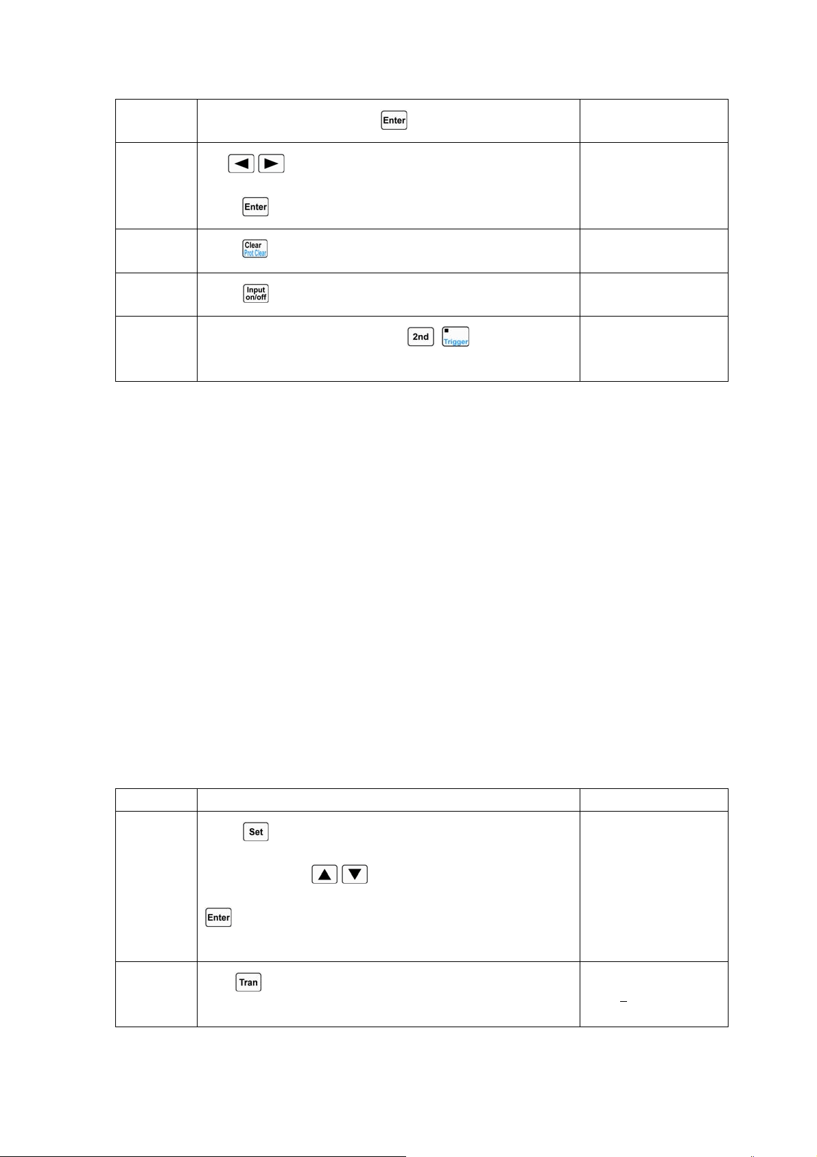
46
set TimeF to 10ms, and press key to confirm.
9
Use
, keys or knob to set Mode value to pulse, and
press
key to confirm.
►Mode: ◄ Puls ►
10
Press
key to exit the transient operation menu.
0.000V 0.000A
1.000A
tCCH OFF
11
Press
key to turn on the load;
0.000V 0.000A
1.000A
tCCH ON
12
One trigger occurs when pressing
+ key or the signal
at the trigger input terminal (TRIG IN) is low level.
0.000V 0.000A
5.000A
tCCH ON
For the above operating procedures, the corresponding SCPI commands should be:
MODE CCH ;Sets the mode
TRAN ON ;Enables the transient operation
CURR:LLEV 1 ;Sets a value to low level
CURR:HLEV 5 ;Sets a value to high level
TRAN:HTIME 200ms ;Sets a value to high level time
TRAN:RTIME 10us ;Sets a value to time for rising edge
TRAN:FTIME 10us ;Sets a value to time for falling edge
TRAN:MODE PULS ;Selects pulsed transient operation
INPUT ON ;Turns on the load
.
.
Trig ; One trigger occurs
4.5.7 Toggled Transient Operation
Example1: Assume that the load is in external triggering mode, set the load resistance value to
periodically switch between 200Ωand 500Ω; set the time for rising edge (TimeR) to10ms; set time
for falling edge (TimeF) to 10ms; the load is in toggled transient operation, and a trigger occurs at this
time.
Procedures Operation Descriptions Display
1
Press
key to enter into the mode selection and parameter
setting menu; use
, keys to select CRH mode; press
key to confirm and exit the mode selection and parameter
setting menu.
0.000V 0.000A
20.000Ω CRH OFF
2
Press
key to enter into transient operation. The display
shows “t” to indicate in CRH status.
0.000V 0.000A
2000.0
Ω tCRH OFF
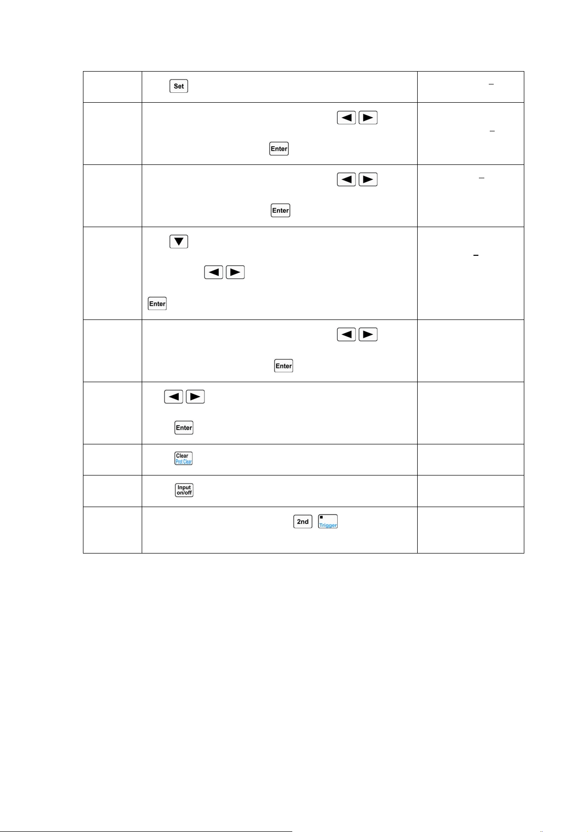
47
3
Press
key to enter into the transient operation menu.
►LevelL:2000.0Ω
LevelH:2000.0Ω
4
Use Entry keys or use the knob together with
, keys to
set LevelL to 200, and press
key to confirm.
LevelL:200.00Ω
►LevelH:2000.0Ω
5
Use Entry keys or use the knob together with
, keys to
set LevelH to 500, and press
key to confirm.
►TimeL:400.00ms
TimeH:200.00ms
6
Press
key to select TimeR; use Entry keys or use the knob
together with
, keys to set TimeR to 10ms, and press
key to confirm.
TimeR:10.00ms
►TimeF:10.00ms
7
Use Entry keys or use the knob together with
, keys to
set TimeF to 10ms, and press
key to confirm.
►Mode: ◄ Puls ►
8
Use
, keys or knob to set Mode value to Togg, and
press
key to confirm.
►Mode: ◄Togg ►
9
Press
key to exit the transient operation menu.
0.000V 0.0000A
200.00Ω
tCRH OFF
10
Press
key to turn on the load;
0.000V 0.0000A
200.00Ω
tCRH ON
11
One trigger occurs when pressing
+ key or the signal
at the trigger input terminal (TRIG IN) is low level.
0.000V 0.0000A
500.00Ω
tCRH ON
For the above operating procedures, the corresponding SCPI commands should be:
MODE CRH ;Sets the mode
TRAN ON ;Enables the transient operation
RES:LLEV 200 ;Sets a value to low level
RES:HLEV 500 ;Sets a value to high level
TRAN:RTIME 10us ;Sets a value to time for rising edge
TRAN:FTIME 10us ;Sets a value to time for falling edge
TRAN:MODE TOGG ;Selects toggled operation
INPUT ON ;Turns on the load
.
.
Trig ; One trigger occurs
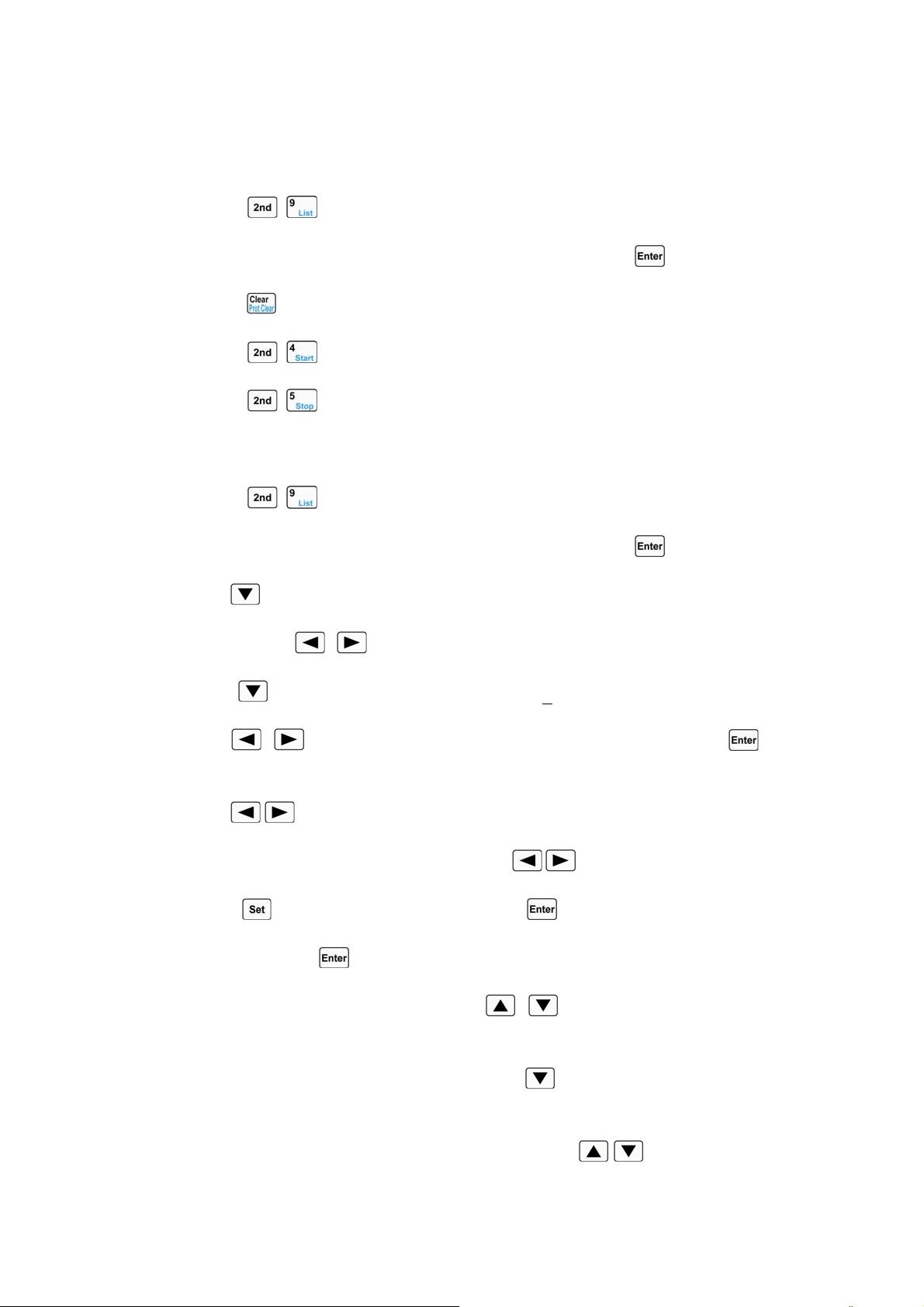
48
4.6 Sequence (List) Operation
After sequence editing, the operating procedures for enabling and disabling sequence operation
are shown as below:
1. Press
+ keys to enter into sequence operation menu.
2. Use Entry keys or the knob to select list number (No.), and press
key to confirm.
3. Press key to exit sequence operation menu.
4. Press
+ keys to activate sequence operation.
5. Press
+ keys to stop sequence operation.
The operating procedures for sequence operation are shown below:
1. Press + keys to enter into sequence operation menu.
2. Use Entry keys or the knob to select list number (No.), and press key to confirm.
3. Use key to select list memo (Memo).
4. Use knob and , keys to edit memo (max. 10 characters).
5. Use key to select sequence data (Data:<New/Edit>)..
6. Use , keys or knob to select New or Edit operation, and press key to
confirm.
7. Use , keys to select parameters.
8. Use Entry keys or use the knob together with , keys to input set value; or use the
knob/
key to select one test mode, and press key to confirm. After setting the third
parameter, press
key to confirm and enter into the next step.
9.
If it is needed to modify one step, use , keys to select this step. The setting
operations for this step are the same as the operating procedure 8.
10. If it is needed to add one step to the last step, use key to select the new step. The setting
operations for this new step are the same as the operating procedure 8.
11. If it is needed to insert one step above an edited step, use
, keys to select this edited
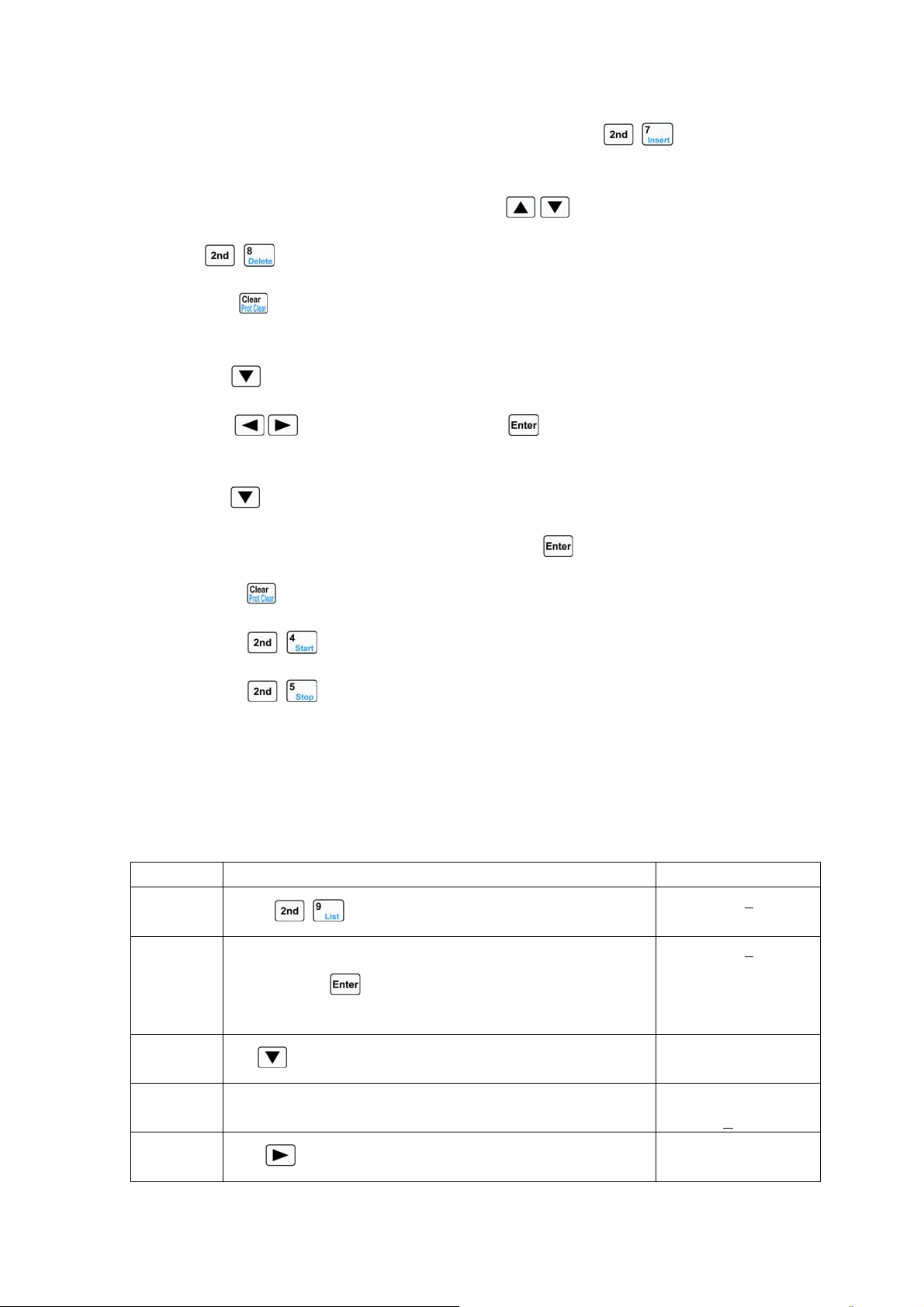
49
step. The LCD display doesn` t flash at this time, and press + keys to insert a new
step. The setting operations for this new step are the same as the operating procedure 8.
12. If it is needed to delete an edited step, use
, keys to select this step, and press
+ keys to delete. If there is only one step exists, it will exit the step edit screen.
13. Press key to exit step edit screen, and save the sequence data in EEPROM assigned by
the sequence number.
14. Use key to select the cycle times (Count); use Entry keys or the knob together
with
, keys to input set value. Press key to confirm and save the cycle times
(Count) in EEPROM assigned by the sequence number.
15. Use key to select “Chain”; use Entry keys (the “Chain” is OFF when the Entry key
exceeds 6) or the knob to input the set value. Press
key to confirm.
16. Press key to exit sequence operation menu.
17. Press + keys to activate sequence operation.
18. Press + keys to stop sequence operation.
4.6.1 Sequence (List) Editing
Example1: Edit a new sequence. The sequence number is 0; the sequence Memo is Test Power;
the sequence steps: step1: CCL, 1A,1S; step2: CCH, 2A, 1S; step3: CV, 1V,1S; step4: CRL, 1Ω,1S;
step5: CRH, 200Ω,1S; the cycle times (Count) for sequence operation is 5; disabling the sequence
chain; starting sequence operation; stopping sequence operation.
Procedures Operation Descriptions Display
1
Press
+ keys to enter into sequence operation menu.
►No.: 0
Memo:
2 Use Entry keys or the knob to set the sequence number (No.) to
0, and press
key to confirm (recall the sequence in
EEPROM assigned by the sequence number).
►No.: 0
Memo:
3
Use
key to select sequence memo (Memo).
No.: 0
►Memo:_
4 Rotate the knob to select the letter “T”. No.: 0
►Memo:T
5
Use
key to move the cursor to the right.
No.: 0
►Memo:T_
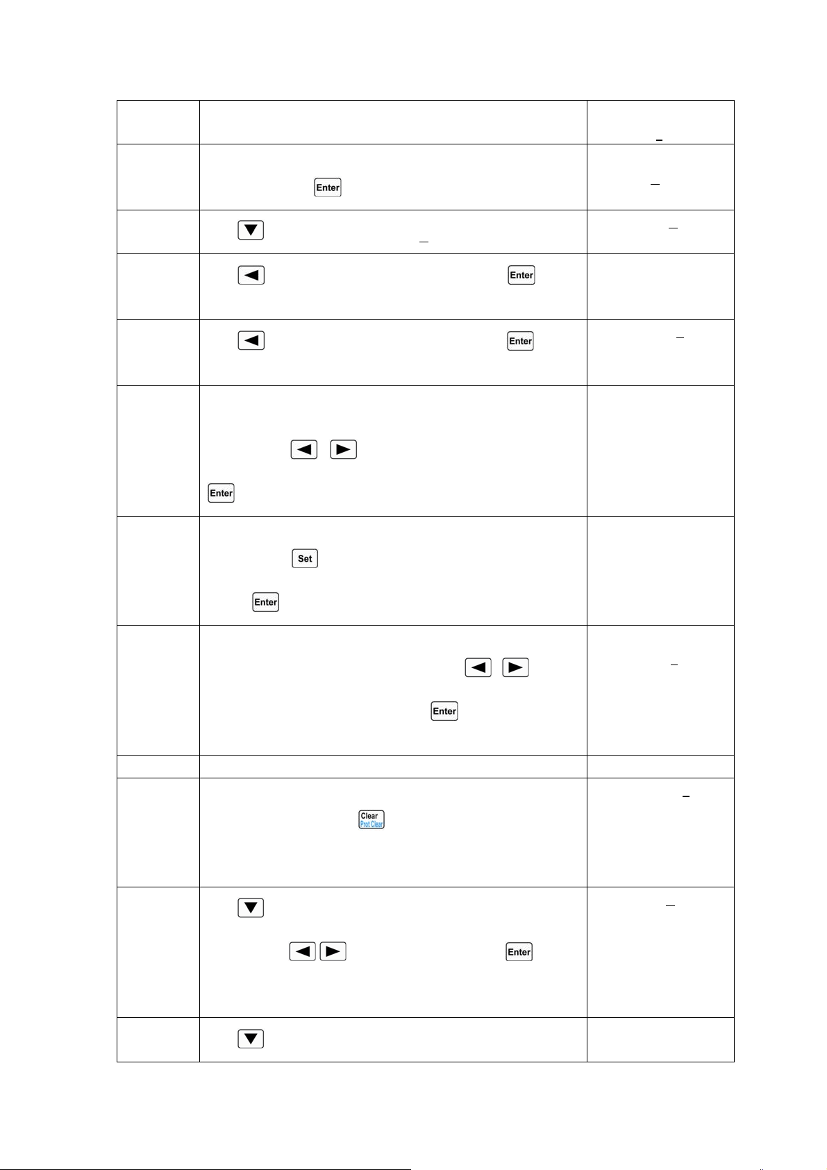
50
6 Rotate the knob to select the letter “e”. No.: 0
►Memo:Te
7 Set Memo to “Test Power” according to step5 and setp6
operations. Press
key to confirm.
No.: 0
►Memo: Test Power
8
Use
key to select Data:<New/Edit>。
►Data:<New/Edit>
Count: 1
9
Use key or knob to select New, and press key to
confirm.
Clear Data:
Yes *No
10
Use key or knob to select Yes, and press key to
confirm. The data is cleared and step edit screen appears.
01. 0.00000s
CCH 0.000A
11 Edit the step1: CCL, 1A, 1S. The time set value in the upper
right corner of the display flashes. Use Entry keys or the knob
together with
, keys to input time to1s, and press
key to confirm.
01. 1.00000s
CCH 0.000A
12 The basic mode in lower left corner of the display flashes. Use
the knob or
key to select operating mode to CCL, and
press
key to confirm.
01. 1.00000s
CCL 0.000A
13 The set value in the lower right corner of the display flashes.
Use Entry keys or the knob together with , keys to
input the current value to 1A. Press
key to confirm and
enter into the next operation.
01. 1.00000s
CCL 1.0000
A
14 Repeat the procedures 11 through 13 to set the rest four steps.
15 The five sequence steps have been edited, and there is no need
to edit the step6. Press
key to exit step edit screen and
save the sequence data in EEPROM assigned by the sequence
number.
06. 0.00000
s
CRH 20.000Ω
16
Use
key to select “Count”; use Entry keys or the knob
together with
, keys to input “5”. Press key to
confirm and save the Count value in EEPROM assigned by the
sequence number.
Data:<New/E
dit>
►
Count: 5
17
Use
key to select “Chain”; use Entry keys (the “Chain”
►Chain:Off
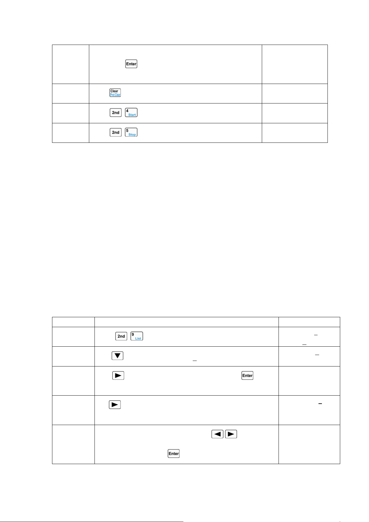
51
is OFF when the Entry key exceeds 6) or the knob to input
“Off”. Press
key to confirm and save the Chain value in
the EEPROM assigned by the sequence number.
18
Press
key to exit sequence operation menu.
0.000V 0.000A
0.000A CCH OFF
19
Press
+ keys to activate sequence operation.
0.000V 0.0000A
1.000A
LCCL ON
20
Press
+ keys to stop sequence operation.
0.000V 0.000A
0.000A CCH OFF
For the above operating procedures, the corresponding SCPI commands should be:
LIST:RECALL 0 ;Recalls the sequence of the number 0
LIST:MEMO Test Power ;Sequence memo is “Test Power”
LIST:DATA CCL,1A,1S
LIST:DATA CCH,2A,1S
LIST:DATA CV,1V,1S
LIST:DATA CRL,1Ω,1S
LIST:DATA CRH,200Ω,1S ;The above 5 commands are sequence steps
LIST:COUNT 5 ;Cycle times for this sequence
LIST:CHAIN OFF ;Disables the chained sequence
LIST ON ;Activates sequence operation
LIST OFF ;Stops sequence operation
4.6.2 Modifying, Adding, Inserting, Deleting the Sequence (List)
Exampel1: Based on the example1 in 4.6.1 section, the step1: modify the time to 2s. Add “CCH,
5A, 1S” to the last step. Insert “CRL , 1Ω,10S” at step3. Delete step2. The sequence is chained to
itself to realize the continuous execution.
Steps Operation Descriptions Display
Step1
Press
+ keys to enter into sequence operation menu.
►No.: 0
Memo: T
est Power
Step2
Use
key to select Data:<New/Edit>。
►Data:<New/Edit>
Count: 5
Step3
Use key or knob to select Edit, and press key to
confirm.
01. 1.00000s
CCL 1.0000A
Step4
Use
key to select time parameter, and the time set value
flashes.
01. 1.00000
s
CCL 1.0000A
Step5
Use Entry keys or the knob together with
, keys to input
the time to 2s, and press
key to confirm.
01. 2.00000s
CCL 1.0000A
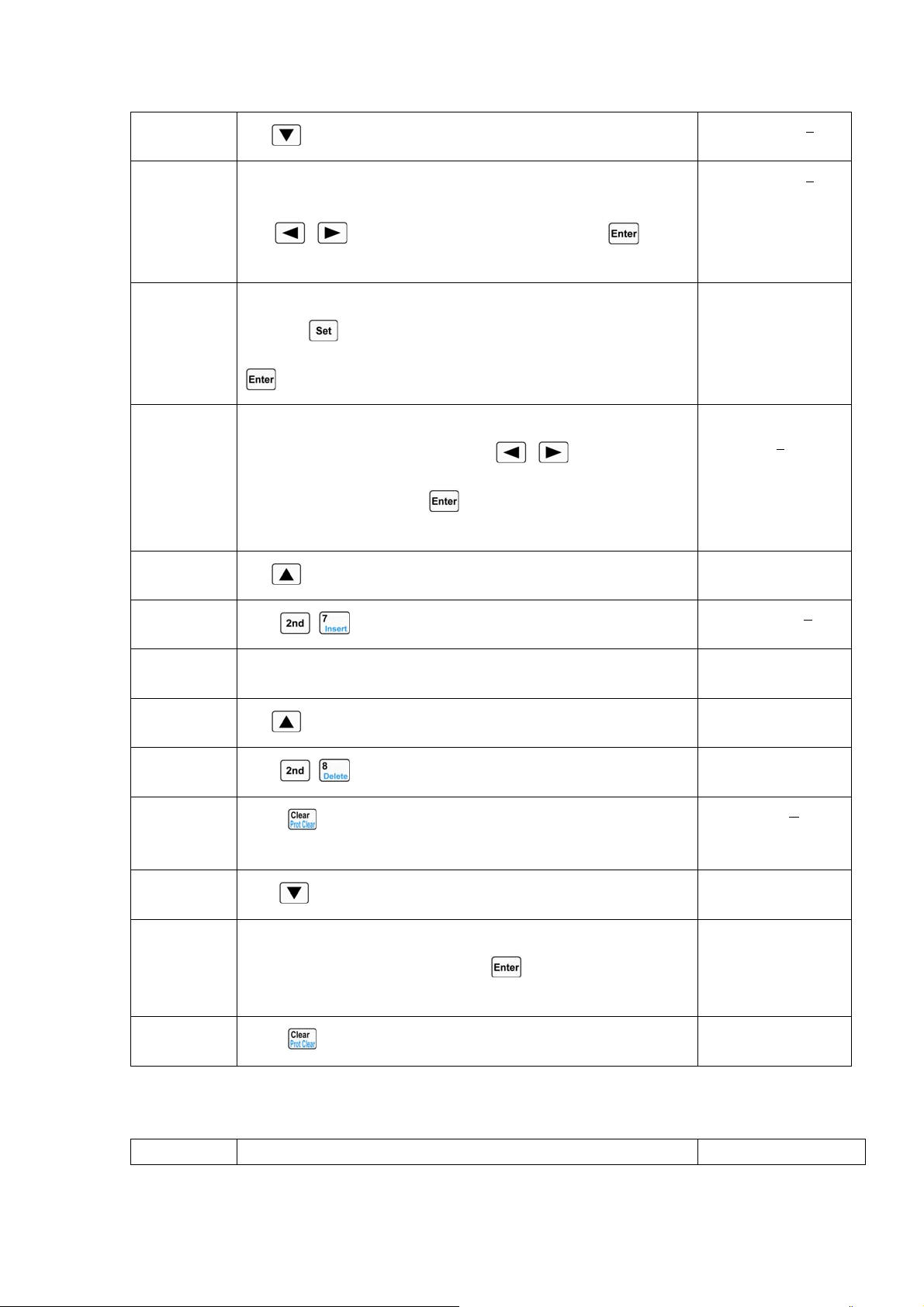
52
Step6
Use
key to select the last new step (Step6).
06. 0.00000
s
CRH 20.000Ω
Step7 Add a new step: CCH, 5A, 1S. The set value in the upper right
corner of the display flashes. Use Entry keys or the knob together
with
, keys to input time to 1s, and press key to
confirm.
06. 1.00000
s
CRH 20.000Ω
Step8 The basic mode in lower left corner of the display flashes. Use the
knob or
key to select operating mode to CCH, and press
key to confirm.
06. 1.00000s
CCH 0.000A
Step9 The set value in the lower right corner of the display flashes. Use
Entry keys or the knob together with , keys to input the
current value to 5A. Press
key to confirm and enter into the
next operation.
06. 1.00000s
CCH 5.000
A
07. 0.00000s
CCH 0.000A
Step10
Use
key to select the step3.
03. 1.00000s
CV 1.000V
Step11
Press
+ keys to insert a new step at step3.
03. 0.00000
s
CV 0.000V
Step12 Insert a new step: CRL, 1Ω,10S at step3. The setting operations for
this new step are the same as the operating procedures7 to 9.
03. 10.00000s
CRL 1.0000Ω
Step13
Use
key to select the step2.
02. 1.00000s
CCH 2.000A
Step14
Press
+ keys to delete the step2.
02. 10.0000s
CRL 1.0000Ω
Step15
Press
key to exit step edit screen and save the sequence data
in EEPROM assigned by the sequence number.
►Data:<New/Edit>
Count: 5
Step16
Use
key to select Chain。
►Chain: Off
Step17 Use Entry keys or the knob to input 0 (it is chained o itself to
realize continuous execution). Press
key to confirm and save
the Chain value in EEPROM assigned by the sequence number.
►Chain: 0
Step18
Press
key to exit sequence operation menu.
0.000V 0.000A
0.000A CCH OFF
4.6.3 Starting/Stopping the Sequence (List)
Example1: Start the No.0 sequence, and stop the active sequence operation.
Steps Operation Descriptions Display
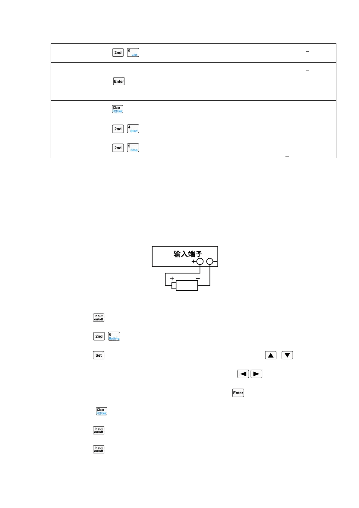
53
Step1
Press
+ keys to enter into sequence operation menu.
►No.: 1
M
emo:
Step2 Use Entry keys or knob to set the sequence number (No.) to 0, an
d
press key to confirm (recall the sequence in EEPROM
assigned by the sequence number).
►No.: 0
Memo: Test Power
Step3
Press
key to exit sequence operation menu.
0.000V 0.000A
0.000
A CCH OFF
Step4
Press
+ keys to activate sequence operation.
0.000V 0.0000A
1.0000A
LCCL ON
Step5
Press
+ keys to stop sequence operation.
0.000V 0.000A
0.000
A CCH OFF
For the above steps, the corresponding SCPI commands should be:
LIST:RECALL 0 ;Recalls the number 0 sequence
LIST ON ;Starts sequence operation
LIST OFF ;Stops sequence operation
4.7 Battery Discharge Operation
Battery discharge operation diagram:
The operating procedures for battery discharge operation are shown below:
1. Press
key to turn off the load, and connect the tested battery correctly.
2. Press
+ keys to enter into battery discharge operation screen.
3. Press key to enter into battery discharge parameters edit screen. Use , keys to
select the parameter. Use Entry keys or the knob together with
, keys to input
termination voltage value and discharge current value. Press
key to confirm.
4. Press key to exit the battery discharge parameters edit screen.
5. Press
key to turn on the load, and start battery discharge operation.
6. Press
key to turn off the load, and stop battery discharge operation.
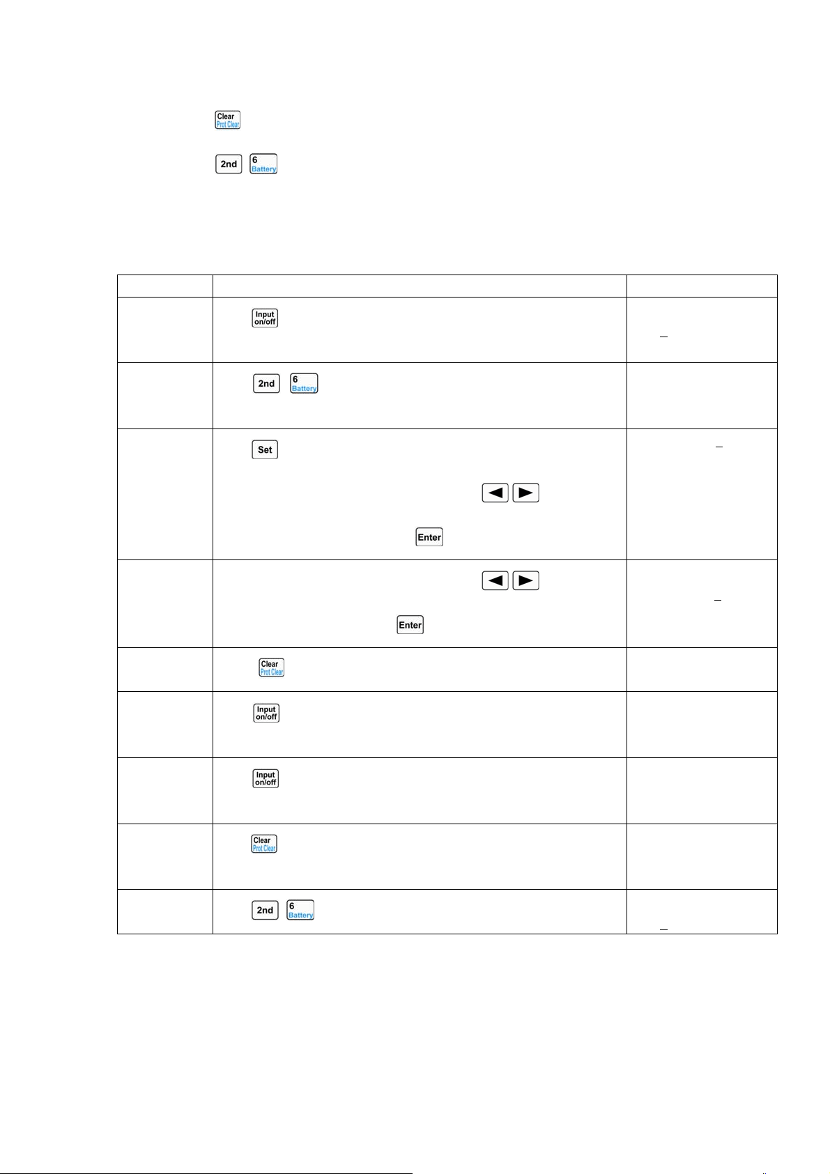
54
7. Press key to clear the discharged time and discharged capacity of the battery.
8. Press
+ keys to exit the battery discharge operation.
Example1: Enter into the battery discharge operation; set the termination voltage to 15V, and the
discharge current to 3A; turn on the load, and start the battery discharge operation; turn off the load
and stop the battery discharge operation; clear the discharged time and discharged capacity of the
battery; exit the battery discharge operation.
Steps Operation Descriptions Display
Step1
Press
key to turn off the load, and connect the tested battery
correctly.
20.000V 0.000A
0.000
A CCH OFF
Step2
Press
+ keys to enter into battery discharge operation
screen.
20.000V 0.000A
0.000AH 00:00:00
Step3
Press
key to enter into battery discharge parameters edit screen.
Use Entry keys or the knob together with
, keys to inpu
t
termination voltage to 15V. Press key to confirm.
►MinVolt:0.000V
DisCurr:2.000A
Step4
Use Entry keys or the knob together with
, keys to inpu
t
discharge current to 3A. Press key to confirm.
MinVolt:15.000V
►DisCurr:3.000A
Step5
Press
key to exit the battery discharge parameters edit screen.
20.000V 0.000A
0.000AH 00:00:00
Step6
Press
key to turn on the load, and start battery discharge
operation.
20.000V 3.000A
0.000AH 00:00:01
Step7
Press
key to turn off the load, and stop battery discharge
operation.
20.000V 0.000A
0.012AH 00:00:15
Step8
Press
key to clear the discharged time and discharged capacity
of the battery.
20.000V 0.000A
0.000AH 00:00:00
Step9
Press
+ keys to exit the battery discharge operation.
20.000V 0.000A
0.000
A CCH OFF
For the above operating procedures, the corresponding SCPI commands should be:
INPUT OFF ;Turns off the load
BATTERY ON ;Activates the battery discharge operation screen
BATT:VOLT:OFF 15V ;Sets termination voltage to 15V
BATT:DIS:CURR 3A ;Sets discharge current to 3A
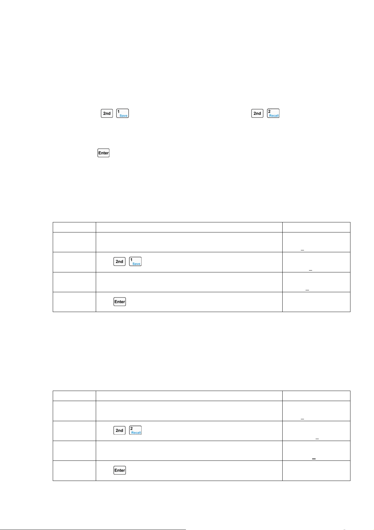
55
INPUT ON ;Turns on the load, and start battery discharge operation
INPUT OFF ; Turns off the load, and stop battery discharge
operationBATTERY OFF ;Exits the battery discharge operation
4.8 Saving and Recalling
The operating procedures for saving and recalling operation are shown below:
1.
Press + keys to enter into the saving menu, or press + keys to enter into
the recalling menu.
2. Press Entry keys or the knob to select saving or recalling position. 选择保存或调用位置。
3. Press key to confirm and exit the saving or recalling menu. If the saving is selected, the
values of List2-1 parameters will be saved in the specified location in EEPROM; if the
recalling is selected, the values of List2-1 parameters should be the values saved in specified
location in EEPROM.
Example1: Set the mode to CCL; set the current value to 2A; turn on the load; save the settings in
location 0 in EEPROM; the next time the load is turned on, these settings will become the power-on
settings.
Procedures Operation Descriptions Display
1 Set the mode to CCL,; set the current value to 2A; turn on the load
(
detailed operations).
0.000V 0.000A
2.0000A CCL ON
2
Press
+ key to enter into the saving menu.
Save File
No. 1
3 Press Entry keys or the knob to select the location 0 for saving.
Save File
No. 0
4
Press key to confirm and exit the load saving menu.
0.000V 0.000A
2.0000A CCL ON
For the above operating procedures, the corresponding SCPI commands should be:
MODE CCH ;Sets the load to CCH status
CURR 2 ;Sets the current value to 2A
*SAV 0 ;Saves the present settings in location0 in EEPROM
Example2: Based on the above example, set the mode to CV; set the voltage value to 40V; turn
off the load; recall the values saved in location0 in EEPROM. The detailed operations are shown
below:
Procedures Operation Descriptions Display
1 Set the mode to CV; set the voltage value to 40V; turn off the loa
d
(please refer to 4.4 section for detailed operations).
0.000V 0.000A
40.000V CV OFF
2
Press
+ keys to enter into the recalling menu.
Recall File:
No. 0
3 Press Entry keys or the knob to select the recalled location 0. Recall File:
No. 0
4
Press key to confirm and return.
0.000V 0.000A
2.0000A CCL ON
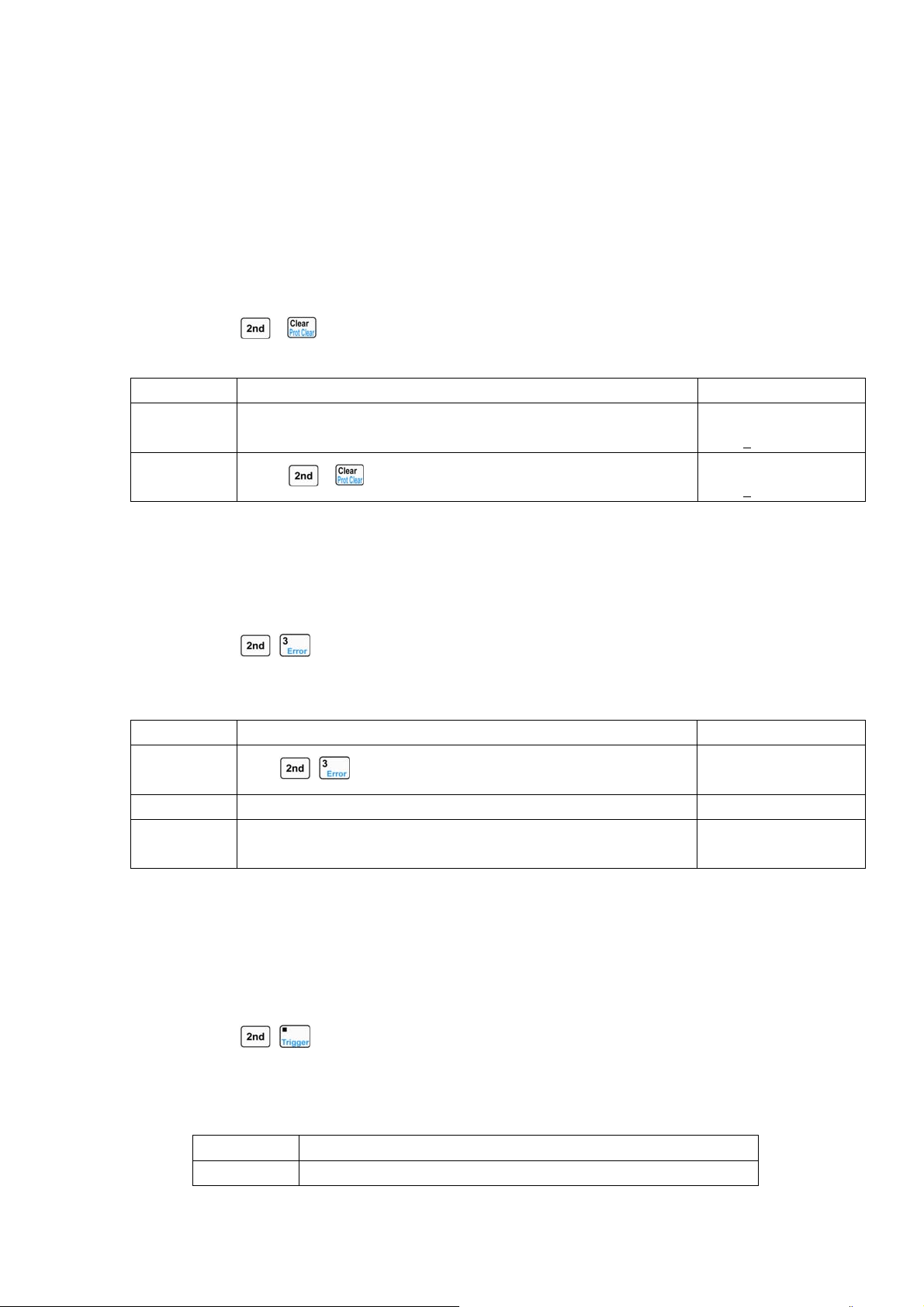
56
For the above operating procedures, the corresponding SCPI commands should be:
MODE CV ;Sets the CV mode
VOLT 40 ;Sets the voltage value to 40V
*RCL 0 ;Recalls the values saved in location 0 in EEPROM
4.9 Clear Protection Settings
The operating procedures for clear protection settings are shown below:
1. Eliminate the reason that causes the protection status.
2. Press
+ keys.
Example1: Clear RV protection of the load. The detailed operations are shown below:
Procedures Operation Descriptions Display
1 Connect the power supply to the load again. 0.000V 0.0000A
2.0000
A RV OFF
2
Press
+ keys.
0.000V 0.0000A
2.0000
A CCL OFF
For the above operating procedures, the corresponding SCPI commands should be:
INP:PROT:CLE ;Clears the protection status
4.10 Error Messages
When an error occurs to the load, the operating procedures are shown below:
1. Press
+ keys to display the error messages.
Example1: When a wrong command is sent, the ERR annunciator will turn red. Check the error
message. The detailed operations are shown below:
Procedures Operation Descriptions Display
1
Press
+ keys to display the error message.
ERROR -103
2 If an error occurs, repeat the first operation.
3 If no error exists, the EER annunciator is turned off. Repeat the
first operation, and display will shows “NO ERROR”.
NO ERROR
For the above operating procedures, the corresponding SCPI commands should be:
SYST:ERR? ;Queries the error code and error messages
4.11 Triggered Operation
When the triggering mode is EXTernal, the triggered operations are shown below:
1. Set trigger object (please see 2.6.2 section for detailed introduction).。
2. Press
+ keys or trigger terminal (TRIG IN) to receive low TTL level, and a trigger
occurs.
Example1: Select “List” for the trigger function to trigger a sequence operation. The sequence is
the one mentioned in Example1 in 4.6.1 section. The detailed operations are shown below:
Steps Operation Descriptions
Step1 Select “List” in main menu for the trigger function (please see
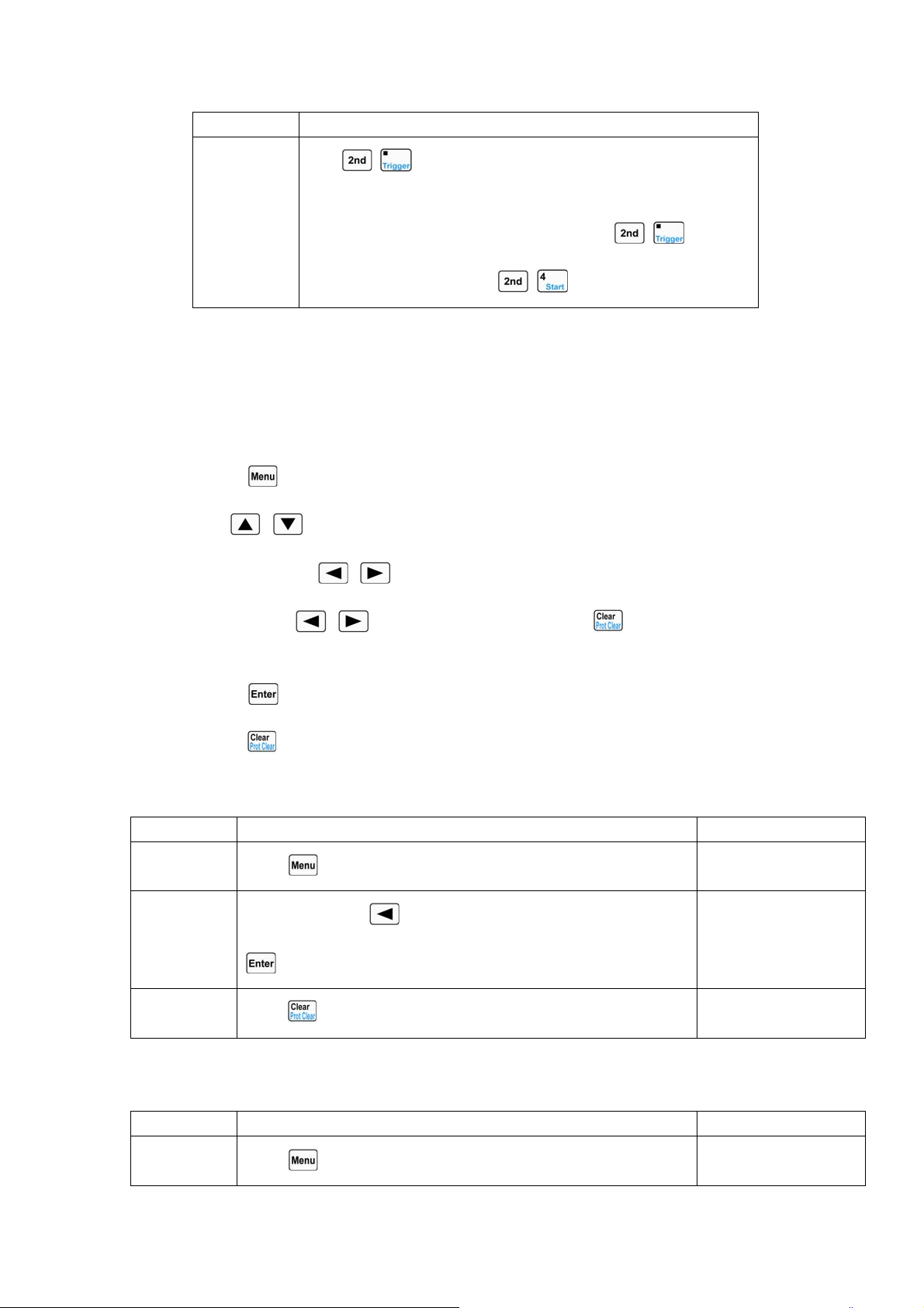
57
4.13.5 section for detailed introduction).
Step2
Press
+ keys or trigger terminal (TRIG IN) to receive low
TTL level. The load` s input will change accordingly when the
sequence parameters are changed. Pressing
+ keys has
the same effect as pressing
+ keys at this time.
For the above operating procedures, the corresponding SCPI commands should be:
TRIG:FUNC LIST ;Selects “LIST” for trigger function
TRIG ;A trigger occurs
4.12 Main Menu
The operating procedures for the main menu are shown below:
1. Press
key to enter into the main menu.
2. Use
, keys to select the menu item.
3. Use the knob or
, keys to select the parameter; or use Entry keys or the knob
together with
, keys to input set value. Press key to exit modifying the
parameter or exit the main menu.
4. Press
key to confirm.
5. Press key to exit the main menu.
4.12.1 Loading Default Values
Example: Load the default values. The detailed operations are shown below:
Procedures Operation Descriptions Display
1
Press
key to enter into the main menu.
Load Default:
Yes *No
2
Use the knob or
key to select the parameter “Yes”. Press
key to confirm.
Load Default:
*Yes No
3
Press
key to exit the main menu.
4.12.2 Short Circuit Operation
Example: Short circuit operation in CV mode. The detailed operations are shown below:
Procedures Operation Descriptions Display
1
Press
key to enter into the main menu.
Load Default:
Yes *No
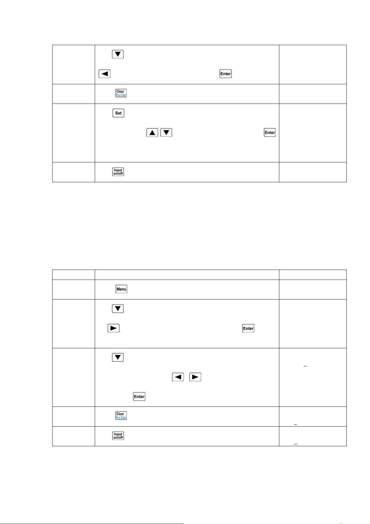
58
2
Use
key to select the menu item “Short”; use the knob or
key to select the parameter “On”. Press key to confirm.
Short
*On Off
3
Press
key to exit the main menu.
4
Press
key to enter into the mode selection and parameter
setting menu; use
, keys to select CV mode. Press
key to confirm and exit the mode selection and parameter setting
menu.
0.000V 0.000A
0.000V sCV OFF
5
Press
key to turn on the load.
0.000V 0.000A
0.000V sCV ON
For the above operating procedures, the corresponding SCPI commands should be:
INPUT:SHORT ON ;Sets the load to short circuit
MODE CV ;Sets the mode
INPUT ON ;Turns on the load
4.12.3 Von Point/Von Latch
Example: Set the Von Latch to Off; set Von Point to 1V; turn on the load; This example
implements the automatic on/off of the load` s input, which simplifies the test operations greatly. The
detailed operations are shown below:
Procedures Operation Descriptions Display
1
Press
key to enter into the main menu.
Load Default:
Yes *No
2
Use
key to select the menu item “Von Latch”; use the knob
or
key to select the parameter “Off”. Press key to
confirm.
Von Latch:
*On Off
3
Use
key to select the menu item “Von Point”; use Entry keys
or the knob together with
, keys to input the voltage
value. Press
key to confirm.
Von Point:
1.000
V
4
Press
key to exit the main menu.
0.000V 0.000A
0.000
A CCH OFF
5
Press
key to turn on the load.
0.000V 0.000A
0.000
A CCH ON
For the above steps, the corresponding SCPI commands should be:
INP:VOLT:ON:LATCH OFF ;Disables the Von Latch
INP:VOLT:ON 1 ;Sets the Von voltage point to 1V
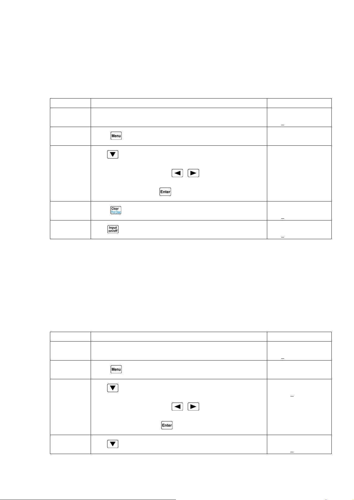
59
INPUT ON ;Turns on the load
4.12.4 Current Limit in CV Mode
Example: Set the load to CV mode; set the voltage value to 2V; set the current limit value in CV
mode (
CV Curr Limit) to 20A; turn on the load. The detailed operations are shown below:
Procedures Operation Descriptions Display
1 Set the load to CV mode, and set the voltage value to 2V (please
see 4.4 section for detailed operations)
0.000V 0.000A
2.000
V CV OFF
Step2
Press
key to enter into the main menu.
Load Default:
Yes *No
Step3
Use
key to select the menu item “CV Curr Limit”; use Entry
keys or the knob together with
, keys to input the current
limit value to 20A. Press
key to confirm.
CV Curr Limit:
20.000A
Step4
Press
key to exit the main menu.
0.000V 0.000A
2.000
A CCH OFF
Step5
Press
key to turn on the load.
0.000V 0.000A
2.000
A CCH ON
For the above operating procedures, the corresponding SCPI commands should be:
MODE CV ;Sets the mode
VOLT 2 ;Sets the current value to 2V
CV:CURR:LIM 20A ;Sets the current limit value to 20A in CV mode
INPUT ON ;Turns on the load
4.12.5 Current Rise/Fall Rate in CC Mode
Example: Set the load to CCH mode, set the current value to 2A; set the current rise rate (Curr
Rise Rate) in CC mode to 0.002A/us; set the current fall rate (Curr Fall Rate) in CC mode to
0.005A/us; turn on the load; turn off the load. The detailed operations are shown below:
Procedures Operation Descriptions Display
1 Set the load to CCH mode, and set the current value to 2A. ((please
see 4.4 section for detailed operations)
0.000V 0.000A
2.000
A CCH OFF
2
Press
key to enter into the main menu.
Load Default:
Yes *No
3
Use
key to select the menu item “Curr Rise Rate”; use Entry
keys or the knob together with
, keys to input the current
value to 0.002A/us. Press
key to confirm.
Curr Rise Rate:
0.002
A/us
4
Use
key to select the menu item “Curr Fall Rate”; use Entry
Curr Fall Rate:
0.005
A/us
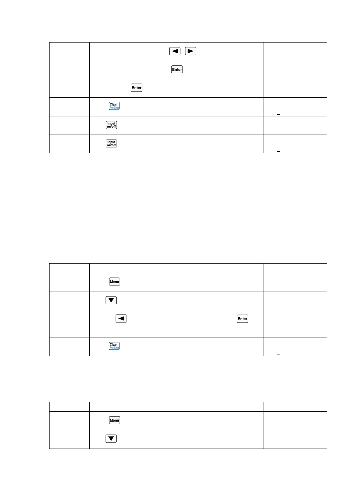
60
keys or the knob together with , keys to input the current
value to 0.005A/us. Press
key to confirm. 电流值
0.002A/us。按
键确定。
5
Press
key to exit the main menu.
0.000V 0.000A
2.000
A CCH OFF
6
Press
key to turn on the load.
0.000V 0.000A
2.000
A CCH ON
7
Press
key to turn off the load.
0.000V 0.000A
2.000
A CCH OFF
For the above operating procedures, the corresponding SCPI commands should be:
MODE CCH ;Sets the mode
CURR 2 ;Sets the current value to 2A 电流值 2V。
CURR:RISE:RATE 0.002 ;Sets the current rise rate in CC mode to 0.002A/us
CURR:FALL:RATE 0.005 ;Sets the current fall rate in CC mode to 0.005A/us 上升速率
为 0.005A/us。
INPUT ON ;Turns on the load
INPUT OFF ;Turns off the load
4.12.6 Trigger Function Selection
Example: Select “Tran” in trigger function selection (Trig Function). 选择(Trig Fonction)为
Tran。
Procedures Operation Descriptions Display
1
Press
key to enter into the main menu.
Load Default:
Yes *No
2
Use
key to select the menu item “Trig Function”; use the
knob or
key to select the parameter “Tran”. Press key
to confirm.
Trig Function:
*Tran List
3
Press
key to exit the main menu.
0.000V 0.000A
0.000
A CCH OFF
For the above operating procedures, the corresponding SCPI commands should be:
TRIG:FUNC TRAN ;Selects transient operation (TRAN) for trigger function
4.12.7 Knob Function
Example: Enable the knob function.
Procedures Operation Descriptions Display
1
Press
key to enter into the main menu.
Load Default:
Yes *No
2
Use
key to select the menu item “Knob”; use the knob or
Knob:
*On Off
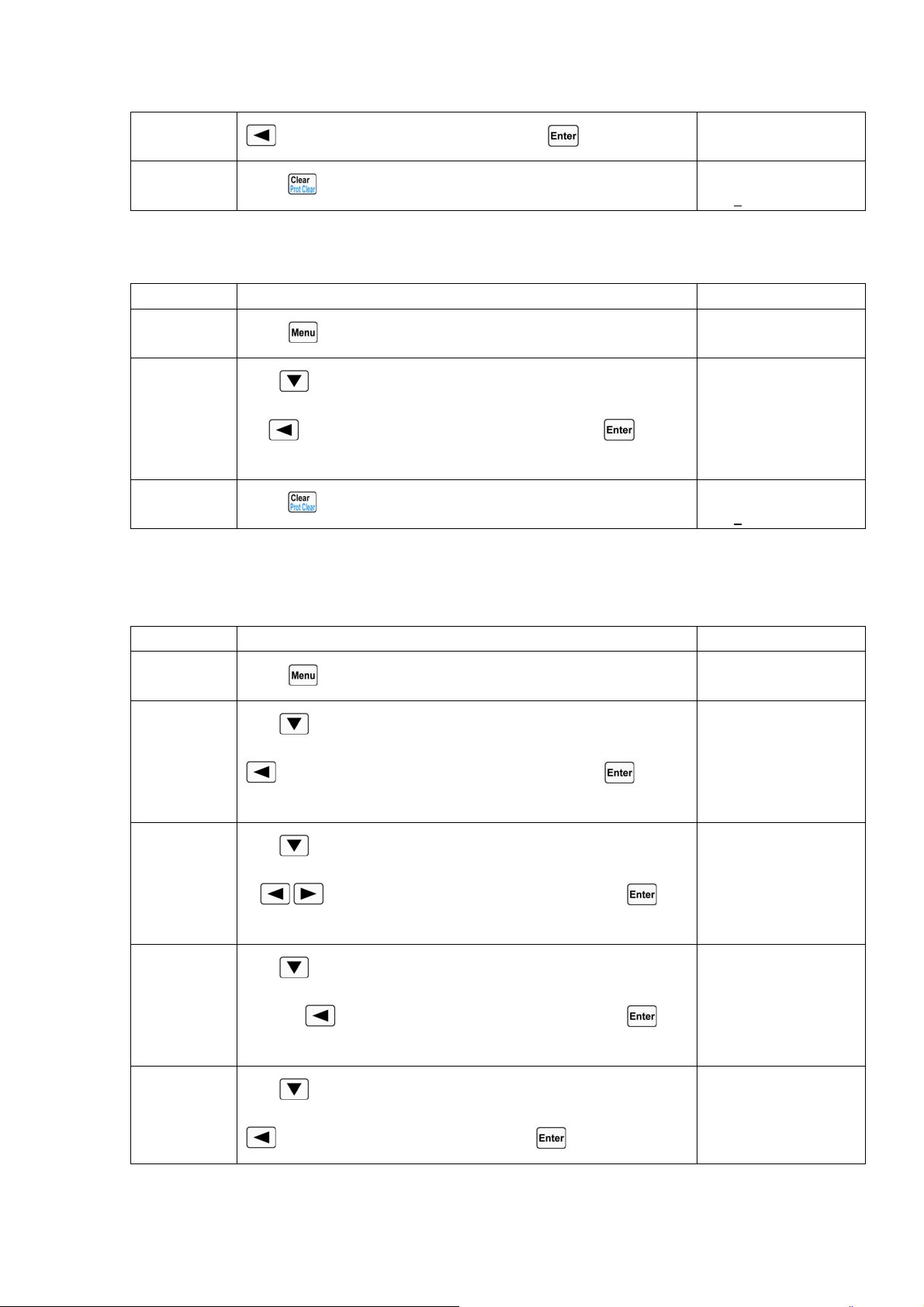
61
key to select the parameter “On”. Press key to confirm.
3
Press
key to exit the main menu.
0.000V 0.000A
0.000
A CCH OFF
4.12.8 Key Sound
Example: Enable the key sound.
Procedures Operation Descriptions Display
1
Press
key to enter into the main menu.
Load Default:
Yes *No
2
Use
key to select the menu item “Key Sound”; use the knob
or
key to select the parameter “On”. Press key to
confirm.
Key Sound:
*On Off
3
Press
key to exit the main menu.
0.000V 0.000A
0.000
A CCH OFF
4.12.9 Communication Interface
Example1: Select RS232 interface; set the baut rate to 9600; set parity check to None; set data bit
to 8; set stop bit to 2; enable the flow control.
Steps Operation Descriptions Display
Step1
Press
key to enter into the main menu.
Load Default:
Yes *No
Step2
Use
key to select the menu item “Interface”; use the knob or
key to select the parameter “RS232”. Press key to
confirm.
Interface:
*RS232 USB GPIB
Step3
Use
key to select the menu item “Baud Rate”; use the knob
or
, keys to select the parameter “9600”. Press key
to confirm.
Baud Rate:
*9600 19200
Step4
Use
key to select the menu item “Parity Check”; use the
knob or
key to select the parameter “None”. Press key
to confirm.
Parity Check:
*None Even Odd
Step5
Use
key to select the menu item “Data Bit”; use the knob or
key to select the parameter “8”. Press key to confirm.
Data Bit:
*8 7
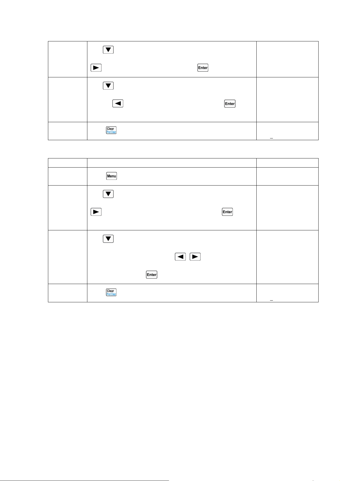
62
Step6
Use
key to select the menu item “Stop Bit”; use the knob or
key to select the parameter “2”. Press key to confirm.
Stop Bit:
1 *2
Step7
Use
key to select the menu item “Flow Control”; use the
knob or
key to select the parameter “On”. Press key to
confirm.
Flow Control:
*On Off
Step8
Press
key to exit the main menu.
0.000V 0.000A
0.000
A CCH OFF
Example2: Select GPIB interface, set the address to 18.
Steps Operation Descriptions Display
Step1
Press
key to enter into the main menu.
Load Default:
Yes *No
Step2
Use
key to select the menu item “Interface”; use the knob or
key to select the parameter “GPIB”. Press key to
confirm.
Interface:
RS232 USB *GPIB
Step3
Use
key to select the menu item “GPIB Address”; use Entry
keys or the knob together wit
, keys to select the
parameter “18”. Press
key to confirm.
GPIB Address:
18
Step4
Press
key to exit the main menu.
0.000V 0.000A
0.000
A CCH OFF
Chapter5 Remote Programming Operation
ARRAY 372x Series Electronic Load supports both local operation and remote control. The
previous chapter has introduced how to use the front panel keys and knobs to operate on the load. This
chapter will introduce you to how to use program the load from the remote controller. The similarities
between local and remote programming will become apparent as you read this chapter. The intent of
this chapter is to help users quickly become familiar with remote programming operations.
Programming examples given in this chapter use the SCPI commands in their simpliest form. Please
refer to the “ARRAY 372x Series Electronic Load SCPI Programming Guide” for detailed introduction
of all SCPI commands.

63
5.1 Communication Interface
5.1.1 RS232
RS232 interface is standard. Use the cable shipped with the load to connect the load to a
computer correctly. Select RS232 interface in the MENU, and set the baud rate, parity, data bit, stop
bit, and flow control parameters to be used. Set the same parameters in the software on the computer,
and input the right SCPI command to operate the load.
5.1.2 USB
USB interface is optional. It can be used only when the load has installed USB communication
module and the relevant driver has installed on the computer. Use USB cable to connect the load to a
computer correctly. Select the USB interface in the MENU and input the right SCPI command to
operate the load.
5.1.3 GPIB
GPIB is optional. It can be used only when the load has installed GPIB communication module
and the relevant driver has installed on the computer. Use GPIB cable to connect the load to a
computer correctly. Select the GPIB interface in the MENU, and set GPIB address. Each instrument
you connect to the GPIB interface has a unique address assigned to it. Input the right SCPI command
to operate the load.
5.2 Flow Control Selection
When RS232 interface is used, the flow control can be enabled or disabled. The load provides
two options: ON and OFF. ON: enabling the flow control; OFF: disabling the flow control. When
“OFF” is selected for flow control, the lower baut rate should be set to ensure normal communication.
5.3 Remote Control Annunciators
There is a REM remote control annunciator on the front panel of the load. When the load receives
the remote command (SYSTem:REMote) via RS232 or GPIB interface, the REM remote control
annunnciator turns on. In remote control status, all operations on the load are controlled by the remote
controller; the front panel keypad and knob has no effect (except
and keys). The REM
remote control annunciator turns off and the load returns to the local control after receiving the
command to return to local control (e.g. :SYST:LOC). Or you can return the load to local control from
remote control by pressing
and keys.
5.4 Sending a Remote Command
You can use the computer to set operation mode and operation parameters remotely for the load.
5.5 Returning Data
The load can return the values of parameter settings, input voltage and current, as well as input
power to computer. It can also return information relating to the internal operation and module
identification. For example: the query “MEAS:CURR?” asks the load to return the actual input
current at the Input binding posts. Please refer to “ARRAY 372x Series Electronic Load SCPI

64
Programming Guide” for detailed information on using queries. The load stores the response to the
query in an output buffer which will hold the information until it is read by the computer or is
replaced with new information.
5.6 Remote Programming Commands
The SCPI commands have many optional key words for the programmer. Getting familiar with
those key words will help you to know the programming better. Most of the commands have a query
syntax which allows the present parameter settings to be returned to the controller. Please refer to
“ARRAY 372x Series Electronic Load SCPI Programming Guide” for details. The load` s major
functions can be programmed with a relatively few number of these commands. The following points
are important to remember when you are remotely programming CC, CR, CV, and CP values.
5.6.1 Modes
The CC, CR, CV, and CP values can be programmed whether or not the associated mode is active.
If the input is turned on, all of the applicable values will take effect at the input when the associated
mode is selected.
5.6.2 Transient Levels
The transient CC, CV, or CR level must be set to a higher level than the respective low level, or
the transient operation will be disabled.
5.6.3 Programmable Current Protection
When programmable current protection is enabled, and the programmed current limit and time
delay are exceeded, the load` s input will be turned off.
5.7 CC Mode Example
This example sets the current level to 0.5A, and then reads back the actual current value.
1 "INPUT OFF" ;Turns off the load` s input
2 "MODE CCL" ;Selects the CCL mode
3 "CURR 0.5" ;Sets current level to 0.5A
4 "INPUT ON" ;Turns on the load` s input
5 "MEAS:CURR?" ;Measures the actual input current
5.7 CV Mode Example
This example presets the trigger voltage to 5V, and selects the external trigger source.
l "INPUT OFF" ;Turns off the load` s input
2 "MODE VOLT" ;Selects the CV mode
3 "VOLT:TRIG 5” ;Presets the trigger voltage to 5V
4 "TRIG:SOUR EXT" ;Selects the external input as the trigger source
5"INPUT ON" ;Turns on the load` s input
In this example, when the external trigger signal is received, the input voltage will be set to 5V.
5.8 CR Mode Example
This example sets the current protection limit to 3A, sets the time delay to 10s, programs the

65
resistance level to 10Ω, and reads back the computed power.
l. "INPUT OFF" ;Turns off the load` s input
2. "MODE CRM" ;Selects the CRM mode
3. "CURR:PROT:LEV 3;DEL 10" ;Sets the current protection limit to 3A, and 10seconds of time
delay
4. "CURR:PROT:STAT ON" ;Activates the current protection
5. "RES 10" ;Sets resistance level to 10Ω
6. "INPUT ON" ;Turns on the load` s input
7. "MEAS:POW?" ;Measures the input power level
5.9 Continuous Transient Operation Example
This example sets CV transient high/low levels, times for transient rising/falling edge, high/low
level times, and parameters for transient operation.
1 "INPUT OFF" ;Turns off the load` s input
2 "MODE CV" ;Selects the CV mode
3 "VOLT:LLEV 0.5" ;Sets the transient low level to 0.5V
4 "VOLT:HLEV 1" ;Sets the transient high level to 1V
5 "TRAN:LTIM 200us" ;Sets transient low level time to 200us
6 "TRAN:HTIM 300us" ;Sets transient high level time to 300us
7 "TRAN:RTIM 10us" ;Sets the time for transient rising edge to 10us
8 "TRAN:FTIM 20us" ;Sets the time for transient falling edge to 20us
9 "TRAN:MODE CONT " ;Selects the continuous transient operation
10 "TRAN ON" ;Activates the transient operation
11 "INPUT ON" ;Turns on the load` s input
5.10 Pulsed Transient Operation Example
This example selects CV pulsed transient operation, selects the bus as the trigger source, and
programs a pulse width of 1 millisecond.
1 "INPUT OFF" ;Turns off the load` s input
2 "MODE CV" ;Selects the CV mode
3 "TRIG:SOUR BUS" ;Selects the bus as the trigger source
4 "VOLT LLEV 0.5" ;Sets the transient low level to 0.5V
5 "VOLT:HLEV 1" ;Sets the transient high level to 1V
6 "TRAN:HTIM 1ms" ;Sets transient high level time to 1ms
7 "TRAN:RTIM 10us" ;Sets the time for transient rising edge to 10us
8 "TRAN:FTIM 10us" ;Sets the time for transient falling edge to 10us
9 "TRAN:MODE PULSE " ;Selects the pulsed transient operation
10 "TRAN ON" ;Activates the transient operation
11 "INPUT ON"
;Turns on the load` s input
12 "*TRG" ;*TRG command generates a 1millisecond high-level pulse at the
load` s input

66