Loading ...
Loading ...
Loading ...
Specifications subject to change without notice.
8 421 01 5501 05
Check Charge
Factory charge amount and desired subcooling are shown
on unit rating plate. Charging method is shown on
information plate inside unit. To properly check or adjust
charge, conditions must be favorable for subcooling
charging. Favorable conditions exist when the outdoor
temperature is between 70_F and 100_F (21.11_C and
37.78_C), and the indoor temperature is between 70 _F and
80_F (21.11_C and 26.67_C).
Follow the procedure below:
Adjust charge by adding or removing 0.6 oz/ft of 3/8 liquid
line above or below 15ft (4.57 m) respectively.
For standard refrigerant line lengths (80 ft/24.38 m or less),
allow system to operate in cooling mode at least 15 minutes.
If conditions are favorable, check system charge by
subcooling method. If any adjustment is necessary, adjust
charge slowly and allow system to operate for 15 minutes to
stabilize before declaring a properly charged system.
If the indoor temperature is above 80_F (26.67_C), and the
outdoor temperature is in the favorable range, adjust system
charge by weight based on line length and allow the indoor
temperaturetodropto80_F (26.67_C) before attempting to
check system charge by subcooling method as described
above.
If the indoor temperature is below 70_F (21.11_C), or the
outdoor temperature is not in the favorable range, adjust
charge for line set length above or below 15ft (4.57 m) only.
Charge level should then be appropriate for the system to
achieve rated capacity. The charge level could then be
checked at another time when the both indoor and outdoor
temperatures are in a more favorable range.
NOTE: If line length is beyond 80 ft (24.38 m) or greater
than 35 ft (10.7 m) vertical separation, see Long Line
Application Guideline for special charging requirements.
Final Checks
IMPORTANT: Before leaving job, be sure to do the following:
1. Ensure that all wiring is routed away from tubing and
sheet metal edges to prevent rub - through or wire
pinching.
2. Ensure that all wiring and tubing is secure in unit
before adding panels and covers. Securely fasten all
panels and covers.
3. Tighten service valve stem caps to 1/12 - turn past
finger tight.
4. Leave Owner’s Manual with owner. Explain system
operation and periodic maintenance requirements
outlined in manual.
CARE AND MAINTENANCE
For continuing high performance and to minimize possible
equipment failure, periodic maintenance must be performed
on this equipment.
Frequency of maintenance may vary depending upon
geographic areas, such as coastal applications. See
Owner’s Manual for information.
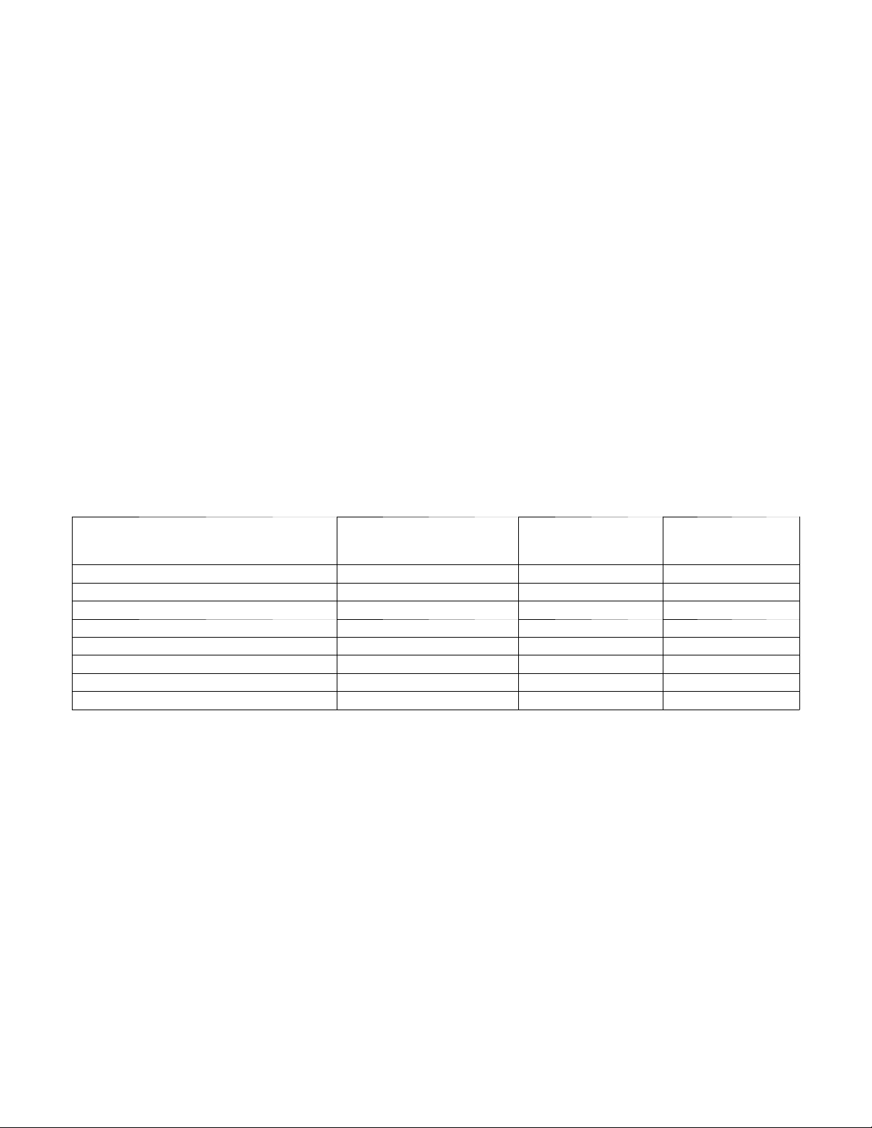
Table6–Accessory Usage
ACCESSORY
REQUIRED FOR LOW- AMBIENT
COOLING APPLICATIONS
(Below 55F/12.8_C)
REQUIRED FOR LONG LINE
APPLICATIONS*
REQUIRED FOR
SEA COAST
APPLICATIONS
(Within 2 miles/3.22 km)
Compressor Start Assist Capacitor and Re lay Ye s Ye s No
Crankcase Heater Ye s Ye s No
Evaporator Freeze Thermostat Ye s No No
Hard Shut- Off TXV Ye s Ye s ‡ No
Liquid Line Solenoid Valve No No No
Low - ambient Pressure Switch Ye s No No
Support Feet Recommended No Recommended
Winter Start Control Ye s * * No No
* For tubing line sets between 80 and 200 ft. (24.38 and 60.96 m) and/or 35 ft. (10.7 m) vertical differential, refer to Long Line Application Guideline.
‡ TXV required beyond 35 ft. (10.7 m) vertical separation or 50 ft. (15.2 m) total length.
** Can only be installed in conjunction with the Low Pressure Switch.
Loading ...
Loading ...