Loading ...
Loading ...
Loading ...
Specifications subject to change without notice.
6 421 01 5501 05
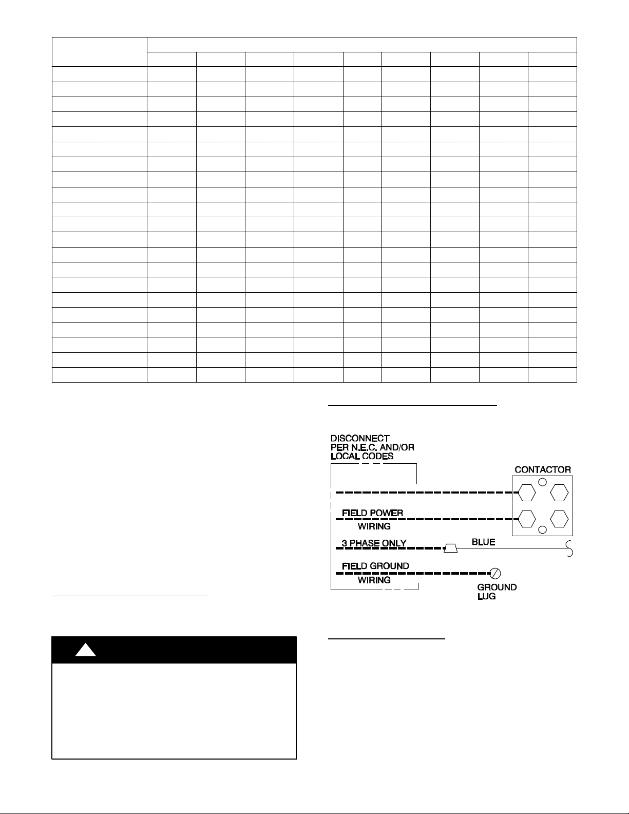
Table4–RequiredSuction-LineTemperature
SUPERHEAT TEMP (_F)
SUCTION PRESSURE AT SERVICE PORT (PSIG)
107.8 112.2 116.8 121.2 126 130.8 138.8 140.8 145.8
0 35 37 39 41 43 45 47 49 51
2 37 39 41 43 45 47 49 51 53
4 39 41 43 45 47 49 51 53 55
6 41 43 45 47 49 51 53 55 57
8 43 45 47 49 51 53 55 57 59
10 45 47 49 51 53 55 57 59 61
12 47 49 51 53 55 57 59 61 63
14 49 51 53 55 57 59 61 63 65
16 51 53 55 57 59 61 63 65 67
18 53 55 57 59 61 63 65 67 69
20 55 57 59 61 63 65 67 69 71
22 57 59 61 63 65 67 69 71 73
24 59 61 63 65 67 69 71 73 75
26 61 63 65 67 69 71 73 75 77
28 63 65 67 69 71 73 75 77 79
30 65 67 69 71 73 75 77 79 81
32 67 69 71 73 75 77 79 81 83
34 69 71 73 75 77 79 81 83 85
36 71 73 75 77 79 81 83 85 87
38 73 75 77 79 81 83 85 87 89
40 75 77 79 81 83 85 87 89 91
Make Electrical Connections
Be sure field wiring complies with local and national fire,
safety, and electrical codes, and voltage to system is within
limits shown on unit rating plate. Contact local power
company for correction of improper voltage. See unit rating
plate for recommended circuit protection device.
NOTE: Operation of unit on improper line voltage constitutes
abuse and could affect unit reliability. See unit rating plate.
Do not install unit in system where voltage may fluctuate
above or below permissible limits.
NOTE: Use copper wire only between disconnect switch
and unit.
NOTE: Install branch circuit disconnect of adequate size per
NEC to handle unit starting current. Locate disconnect within
sight from and readily accessible from unit, per Section
440 - 14 of NEC.
Route Ground and Power Wires
Remove access panel to gain access to unit wiring. Extend
wires from disconnect through power wiring hole provided
and into unit control box.
!
WARNING
ELECTRICAL SHOCK HAZARD
Failure to follow this warning could result in personal
injury or death.
The unit cabinet must have an uninterrupted or unbroken
ground to minimize personal injury if an electrical fault
should occur. The ground may consist of electrical wire
or metal conduit when installed in accordance with
existing electrical codes.
Connect Ground and Power Wires
Connect ground wire to ground connection in control box for
safety. Connect power wiring to contactor as shown in Fig. 5.
A94025
Fig. 5 - Line Connections
Connect Control Wiring
Route 24 - v control wires through control wiring grommet and
connect leads to control wiring (See Fig. 7). Refer to
Installation Instructions packaged with thermostat.
Use No. 18 AWG color- coded, insulated (35_C minimum)
wire. If thermostat is located more than 100 ft. (30.48 m)
from unit, as measured along the control voltage wires, use
No. 16 AWG color- coded wire to avoid excessive voltage
drop.
All wiring must be NEC Class 2 and must be separated from
incoming power leads.
Loading ...
Loading ...
Loading ...