Loading ...
Loading ...
Loading ...
Specifications subject to change without notice.
4 421 01 5501 05
Evacuate Refrigerant Tubing and Indoor
Coil
CAUTION
!
UNIT DAMAGE HAZARD
Failure to follow this caution may result in equipment
damage or improper operation.
Never use the system compressor as a vacuum
pump.
Refrigerant tubes and indoor coil should be evacuated using
the recommended deep vacuum method of 500 microns.
The alternate triple evacuation method may be used (see
triple evacuation procedure in service manual). Always
break a vacuum with dry nitrogen.
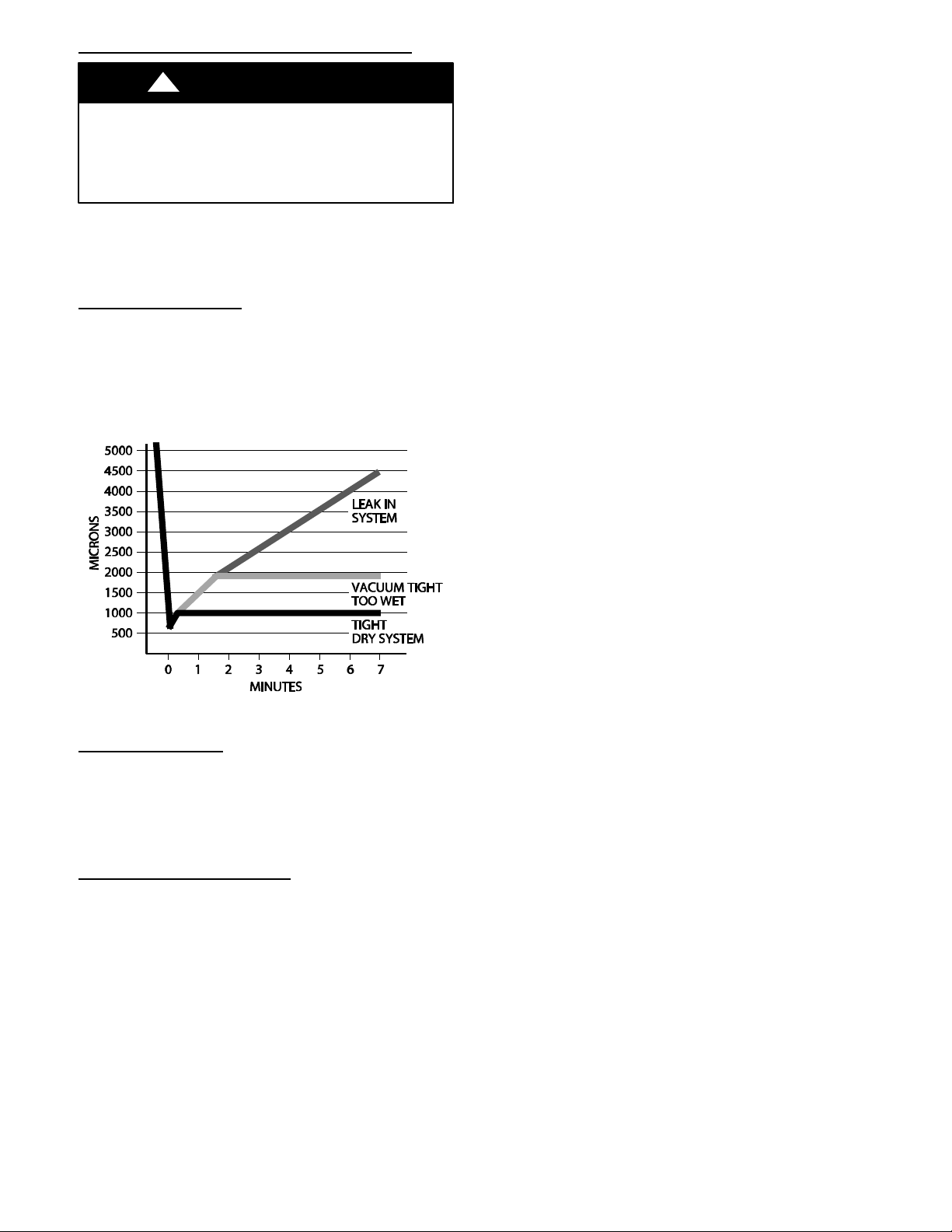
Deep Vacuum Method
The deep vacuum method requires a vacuum pump capable
of pulling a vacuum of 500 microns and a vacuum gage
capable of accurately measuring this vacuum depth. The
deep vacuum method is the most positive way of assuring a
system is free of air and liquid water. A tight dry system will
hold a vacuum of 1000 microns after approximately 7
minutes. See Fig. 4.
A95424
Fig. 4 - Deep Vacuum Graph
Final Tubing Check
IMPORTANT: Check to be certain factory tubing on both
indoor and outdoor unit has not shifted during shipment.
Ensure tubes are not rubbing against each other or any
sheet metal or wires. Pay close attention to feeder tubes,
making sure wire ties on feeder tubes are secure and tight.
Installing with Indoor Piston
Air Conditioner Matched with Factory Approved Piston
Indoor
Air conditioners may be installed with piston fan coils as a
system when the air conditioner and fan coil are listed as a
system in the AHRI directory. All rated piston fan coils are
shipped with the appropriate size piston for the equal
tonnage air conditioner. Matching air conditioners with piston
indoors of larger tonnage size requires a TXV.
Air Conditioner Applied as Replacement Component
If the air conditioner is installed as a replacement component
in an existing piston indoor system, the piston size in the
indoor unit should be changed to the size required for the air
conditioner which can be found in the Specification Sheet.
Units with Cooling Mode TXV
Units installed with cooling mode TXV require charging by
the subcooling method.
1. Operate unit a minimum of 15 minutes before
checking charge.
2. Measure liquid service valve pressure by attaching an
accurate gage to service port.
3. Measure liquid line temperature by attaching an
accurate thermistor type or electronic thermometer to
liquid line near outdoor coil.
4. Refer to unit rating plate for required subcooling
temperature.
5. Refer to Table 2 - Rating Plate (required) Subcooling
Temperature. Find the point where required
subcooling temperature intersects measured liquid
service valve pressure.
6. To obtain required subcooling temperature at a
specific liquid line pressure, add refrigerant if liquid line
temperature is higher than indicated or reclaim
refrigerant if temperature is lower. Allow a tolerance of
3_F(1.7_C).
Units with Indoor Piston
Units installed with indoor pistons require charging by the
superheat method.
The following procedure is valid when indoor airflow is within
21 percent of its rated CFM.
1. Operate unit a minimum of 15 minutes before
checking charge.
2. Measure suction pressure by attaching an accurate
gage to suction valve service port.
3. Measure suction temperature by attaching an accurate
thermistor type or electronic thermometer to suction
line at service valve.
4. Measure outdoor air dry bulb temperature with
thermometer.
5. Measure indoor air (entering indoor coil) wet- bulb
temperature with a sling psychrometer.
6. Refer to Table 3 - Superheat Charging - AC Only.
Find outdoor temperature and evaporator entering air
wet- bulb temperature. At this intersection, note
superheat. Where a dash (- - ) appears on the table,
do not attempt to charge system under these
conditions or refrigerant slugging may occur. Charge
must be weighted in, adding or removing 0.6 oz/ft of
3/8 liquid line above or below 15 feet (4.6m)
respectively.
7. Refer to Table 4 - Required Suction- Line
Temperature. Find superheat temperature (from #6
above) and suction pressure. At this intersection, note
suction line temperature.
8. If unit has a higher suction line temperature than
charted temperature, add refrigerant until charted
temperature is reached.
9. If unit has a lower suction line temperature than
charted temperature, reclaim refrigerant until charted
temperature is reached.
10. When adding refrigerant, c harge in liquid form into
suction service port using a flow- restricting device.
11. If outdoor air temperature or pressure at suction valve
changes, charge to new suction line temperature
indicated on chart.
12. Optimum performance will be achieved when the
operating charge produces 10_F suction superheat at
suction service valve with 95_F(35_C) outdoor
ambient and 80_F(27_C) dry bulb (67_F/19
_C) wet
bulb) indoor temperature (DOE “A” test conditions) at
rated airflow.
Loading ...
Loading ...
Loading ...