Loading ...
Loading ...
Specifications subject to change without notice.
421 01 5501 05 3
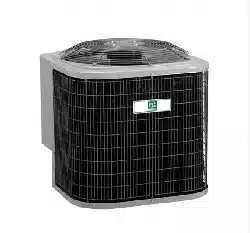
3/8- in. (9.53 mm) Dia.
Tiedown Knockouts in
Basepan(2) Places
View From Top
UNIT BASE PAN
Dimension in. (mm)
TIEDOWN KNOCKOUT LOCATIONS in. (mm)
A B C
23- 1/2 X 23 - 1/ 2
(596.9 X 596.9)
7- 13/16 (198.4) 4–7/16 ( 112.7) 18–1/16 (458.8)
26 X 26
(660.4 X 660.4)
9–1/8 ( 231.8) 4–7/16 ( 112.7) 21–1/4 ( 539.8)
31–1/2 X 31–1/2
(800.1 X 800.1)
9–1/8 ( 231.8) 6–9/16 ( 166.7) 24–11/16 ( 627.1)
35 X 35
(889 X 889)
9–1/8 ( 231.8) 6–9/16 (166.7) 28–7/16 (722.3)
A05177
Fig. 2 - Tiedown Knockout Locations
Outdoor units may be connected to indoor section using
accessory tubing package or field- supplied refrigerant grade
tubing of correct size and condition. Rated tubing diameters
shown in Table 1 are recommended up to 80 ft. (24.38 m).
See Specification Sheets for acceptable alternate vapor
diameters and associated capacity losses. For tubing
requirements beyond 80 ft. (24.38 m), substantial capacity
and performance losses can occur. Following the
recommendations in the Long Line Application Guideline
will reduce these losses. Refer to Table 1 for field tubing
diameters. Refer to Table 6 for accessory requirements.
There are no buried - line applications greater than 36 - in.
(914.4 mm) allowed.
If refrigerant tubes or indoor coil are exposed to atmosphere,
they must be evacuated to 500 microns to eliminate
contamination and moisture in the system.
Outdoor Unit Connected to Factory Approved
Indoor
Unit
Outdoor unit c ontains correct system refrigerant charge for
operation with factory approved AHRI rated indoor unit when
connected by 15 ft. (4.57 m) of field - supplied or
factory- accessory tubing, and factory supplied filter drier.
Check refrigerant charge for maximum efficiency.
Refrigerant Tubing Connection Outdoor
Connect vapor and liquid tubes to fittings on vapor and liquid
service valves (see Table 1.) Use refrigerant grade tubing
Sweat Connection
CAUTION
!
UNIT DAMAGE HAZARD
Failure to follow this caution may result in equipment
damage or improper operation.
Service v alves must be wrapped in a heat- sinking
material such as a wet cloth while brazing.
Use refrigeration grade tubing. Service valves are closed
from factory and ready for brazing. After wrapping service
valve with a wet cloth, braze sweat connections using
industry accepted methods and materials. Consult local code
requirements. Refrigerant tubing and indoor coil are now
ready for leak testing. This check should include all field and
factory joints.
Table1–RefrigerantConnections and Recommended
Liquid and Vapor Tube Diameters (In.)
UNIT SIZE
LIQUID RATED VAPOR*
Connection
&Max.Tube
Diameter
Connection
Diameter
Tube
Diameter
18, 24 3/ 8 3/4 3/4
30 3/8 3/4 3/4
36 3/8 7/8 7/8
42, 48 3/ 8 7/8 7/8
60 3/8 7/8 1- 1/8
* Units are rated with 25 ft. (7.6 m) of lineset. See Specification sheet for
performance data when using different size and length linesets.
Notes:
1. Do not apply capillary tube coils to these units.
2. For Tubing Set lengths between 80 and 200 ft. (15.2 and 61.0 m)
horizontal or 35 ft. (10.7 m) vertical differential 250 ft. (76.2 m) Total
Equivalent Length), refer to the Long Line Application Guideline
3. For alternate liquid line options on 18- 42 size units, see Specification
Sheet or
Long Line Application Guideline
Install Liquid- Line Filter Drier Indoor
CAUTION
!
UNIT DAMAGE HAZARD
Failure to follow this caution may result in equipment
damage or improper operation.
1. Installation of filter drier in liquid line is required.
2. Filter drier must be wrapped in a heat- sinking
material such as a wet cloth while brazing.
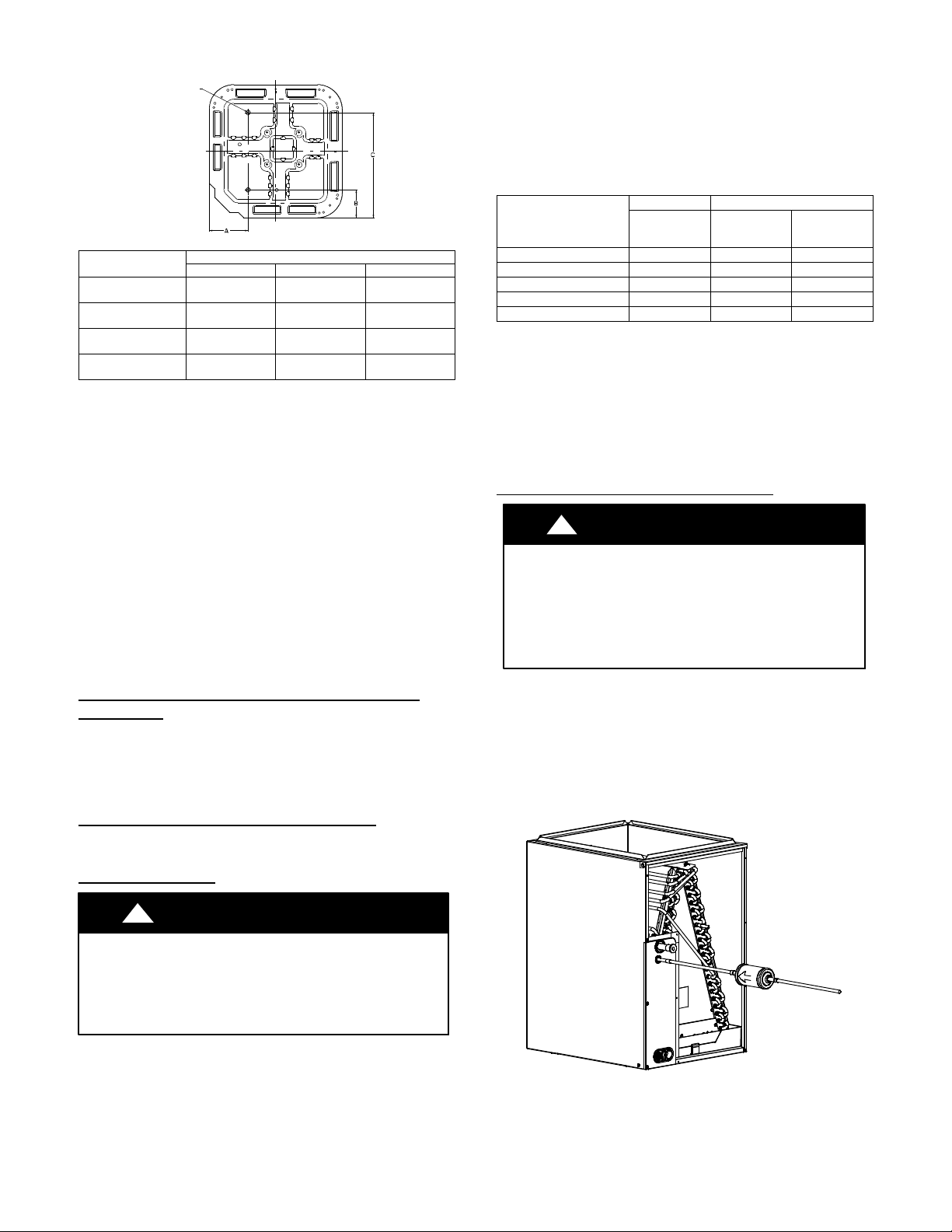
Refer to Fig. 3 and install filter drier as follows:
1. Braze 5 - in. liquid tube to the indoor coil.
2. Wrap filter drier with damp cloth.
3. Braze filter drier to above 5 - in. (127 mm) liquid tube.
Flow arrow must point towards indoor coil.
4. Connect and braze liquid refrigerant tube to the filter
drier.
A05178
Fig. 3 - Liquid Line Filter Drier
Loading ...
Loading ...
Loading ...