Loading ...
Loading ...
Loading ...
8.2 Test Run
a)
Set the “TEST RUN” mode by pressing the “MODE” and “CHECK” switch of controller simultaneously for at least 3
seconds.
"TEST RUN" is displayed on the LCD.
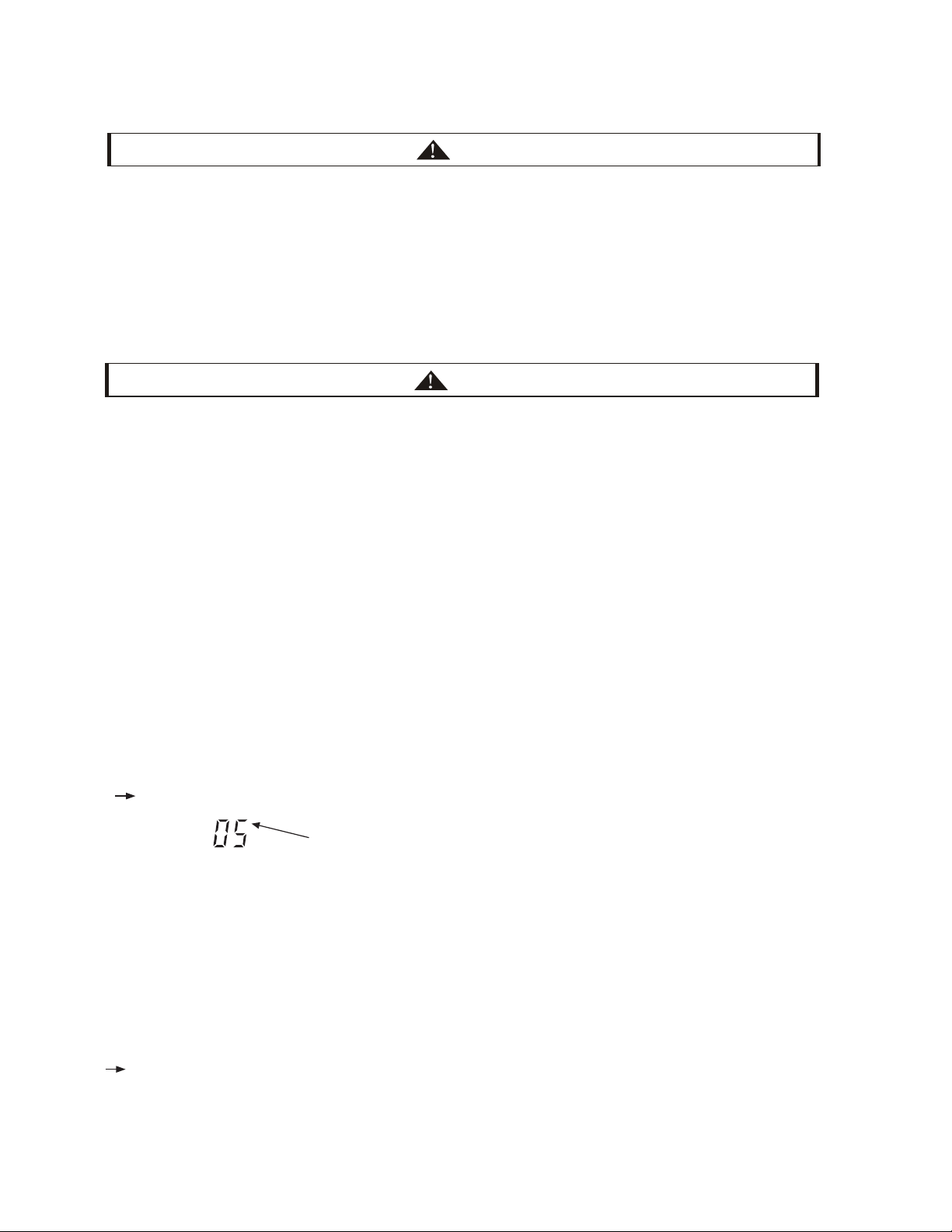
The total number of the indoor units connected is indicated on the LCD.
unit
Example when 5 indoor units are connected.
Regarding other optional remote control switch (wireless remote control or half-size remote control), follow
“Installation & Maintenance Manual” attached to each optional remote control switch and perform the test run.
In case that the multiple indoor units operate simultaneously controlled by one remote control switch, check the
connected number of indoor unit is indicated on LCD.
In case that the indicated number is not correct, the auto-address function is not performed correctly due to incorrect
wiring, the electric noise or etc. Turn OFF the power supply and correct the wiring after checking the following points;
(Do not repeat turning ON and OFF within 10 seconds.)
Power Supply for Indoor Unit is Not Turned ON or Incorrect Wiring.
Incorrect Connection of Connecting Cable between Indoor Units or Incorrect Connection of Controller Cable
Incorrect Setting of Rotary Switch and Dip Switch (The Setting is overlapped.) on the Indoor Units PCB.
b)
Set the operation mode by pressing “MODE” switch.
c)
Press “RUN/STOP” switch.
The operation lamp will be turned ON before the test run starts.
2-hour OFF Timer will be set automatically, and “OFF Timer” and “2HR” will be indicated LCD. Although the air flow
initial setting is “HI”, the setting can be changed.
(1) Check to ensure that the stop valves of the outdoor unit are fully opened and then start the system.
(In case of the combination module, check that the stop valves of all the connected outdoor units are fully opened.)
NOTE: Low pressure gas is used for heat recovery system only.
(2) Perform the test run of indoor units one by one sequentially and then check corresponding refrigerant piping
system and electrical wiring system. (If multiple indoor units operate simultaneously, the system can not be checked
for the system accordance.)
(3) Perform the test run according to the following procedure. Ensure that the test run is carried out without any problem.
NOTE:
In case of 2-remote control switch (main and sub), firstly perform the test run of the main remote control switch.
●
●
*
*
*
1.
NO
Confirm that field-supplied electrical components (main switch fuse, fuse-free breaker, earth leakage breakers,
wires, conduit connectors and wire terminals) have been properly selected according to the electrical data given in
the Technical Catalog of the unit and ensure that the components comply with national and local codes.
Use shielded wires (>18AWG(0.75mm
2
)) for field wiring to protect from electric noise obstacle (total length of
shielded wire shall be less than 3230.8ft.(1000m), and size of shielded wire shall comply with local codes).
Check to ensure that the terminal for power source wiring (the voltage of terminals “L1” to “L1” and of shielded
wire shall comply with local codes.). If not, some components will be damaged.
3.
2.
TICE
CAUTION
If the leakage breaker is activated, check the recommended size shown in Table 6.1.
Caution for Insulation Resistance:
If total unit insulation resistance is lower tha
n 1MΩ, the compressor insulation resistance may be low due to
retained refrigerant in the compressor. This may occur if the unit has not been used for a long period.
1. Disconnect the cables to the compressor and measure the insulation resistance of the compressor itself. If the
resistance value is ove
r 1MΩ, then insulation failure has occurred for other electrical parts.
2.
If the insulation resistance is less th
an 1MΩ, disconnect the compressor cable from the inverter PCB. Then, turn on the
main power to apply current to the crankcase heater. After applying current for more than 3 hours, measure insulation
resistance again. (Depending on the air conditions, pipe length or refrigerant conditions, it may be necessary to apply
the current for a longer period of time.) Check the insulation resistance and reconnect the compressor.
CAUTION
(D) After the initial test run, please clean the water filter and make sure that the filter mesh is clean and free of
impurities.
Loading ...
Loading ...
Loading ...