Loading ...
Loading ...
Loading ...
30
Charge the correct refrigerant quantity.
If not, compressor may be damaged
due to an excessive or insufficient
refrigera
nt charge.
Refrigerant charging from check joint of
gas stop valve may lead to compressor
failure. Be sure to charge refrigerant
from the check joint of liquid stop valve.
Insulate the liquid piping and gas piping
completely to avoid decreasing of
performance and dewing on the surface
of the pipe.
Insulate the flare nut and union of the
piping connection with insulation.
Check to ensure that there is no gas
leakage. If a severe refrigerant leakage
occurs, it will cause difficulty with
breathing or harmful gases would
generate when contacting with fire in the
room
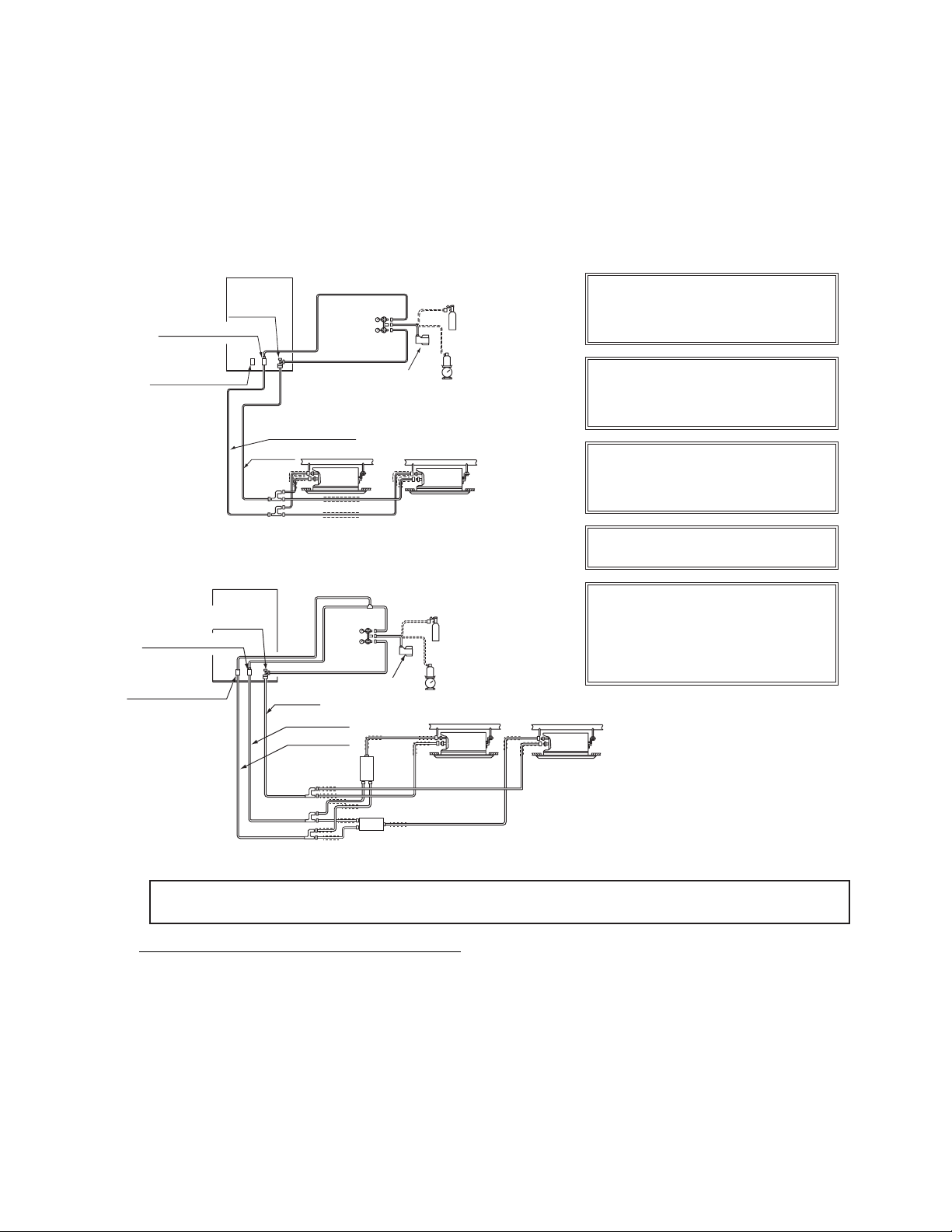
Stop Valve
(Liquid Piping)
Stop Valve
(High/Low Pressure Gas Piping)
Stop Valve
(Low Pressure Gas Piping)
High/Low Pressure Gas Piping
Liquid Piping
Insulation
Switch BOX
[Cover the gas and liquid piping with insulation.]
Switch BOX
Outdoor Unit
Vacuum Pump
Siphonic Refrigerant Cylinder
(R410A)
Weigher
Nitrogen Tank
(for Nitrogen Purging during
Brazing and Air Tight Test)
Indoor Unit
Manifold Pipe
Manifold
Gauge
Insulation
Outdoor Unit
Stop Valve
Manifold
Gauge
Vacuum Pump
Nitrogen Tank
(for Nitrogen Purging during
Brazing and Air Tight Test)
Siphonic Refrigerant Cylinder
(R410A)
Weigher
High/Low
Pressure Gas Piping
Liquid Piping
(Liquid Piping
Stop Valve
(High/Low Pressure Gas Piping)
Stop Valve
(Low Pressure Gas Piping)
Manifold Pipe
Insulation
< Heat Recovery System >
Indoor Unit
(or Water Module)
[Cover the gas and liquid piping with insulation.]
(or Water Module)
Low Pressure
Gas Piping
7.3 Charging Operation
After vacuum pumping, check that the gas and liquid stop valves are completely closed.
Charge additional refrigerant (tolerance: 1.1lbs(0.5kg)) from the check joint of liquid stop valve. If the
specified refrigerant quantity can not be charged, follow the procedure below.
Fully open the stop valve for gas side
(In case of heat recovery system, fully open the stop valve for
high/low pressure and low
pressure gas pipe).
(2)
RTotally Charged Refrigerant Quantity in System (kg)
VRoom Volume for each Indoor Unit (ft
3
)
CCritical Concentration 0026lbs/ft
3
02
)
●
Special Attention Regarding Refrigerant Gas Leakage
Pay attention to the critical gas concentration to avoid accidental refrigerant gas leakage before installing
air conditioning systems.
≤
(1)
(2)
(2)
Operate the compressor in cooling mode and charge refrigerant (tolerance: 1.1lbs(0.5kg)) from the
check joint of the liquid stop valve. At this time,
the
liquid stop valve is slightly opened.
(3)
(3)
(3)
After refrigerant charge, fully open the stop valve for both liquid and gas sides.
* This value should be decided according to the each country’s regulationIS197SHR
S1Iis higher than , take the following actions:
1) Provide a gas leakage detector and fan controlled by its gas leakage detector.
2) Provide effective opening in the wall or door for ventilation to next door so that the critical gas concentrationcan
be maintained lower than the above value. (n opening 0.15% of floor surface at
the lowerpart of a door.)
Loading ...
Loading ...
Loading ...