Loading ...
Loading ...
Loading ...
15
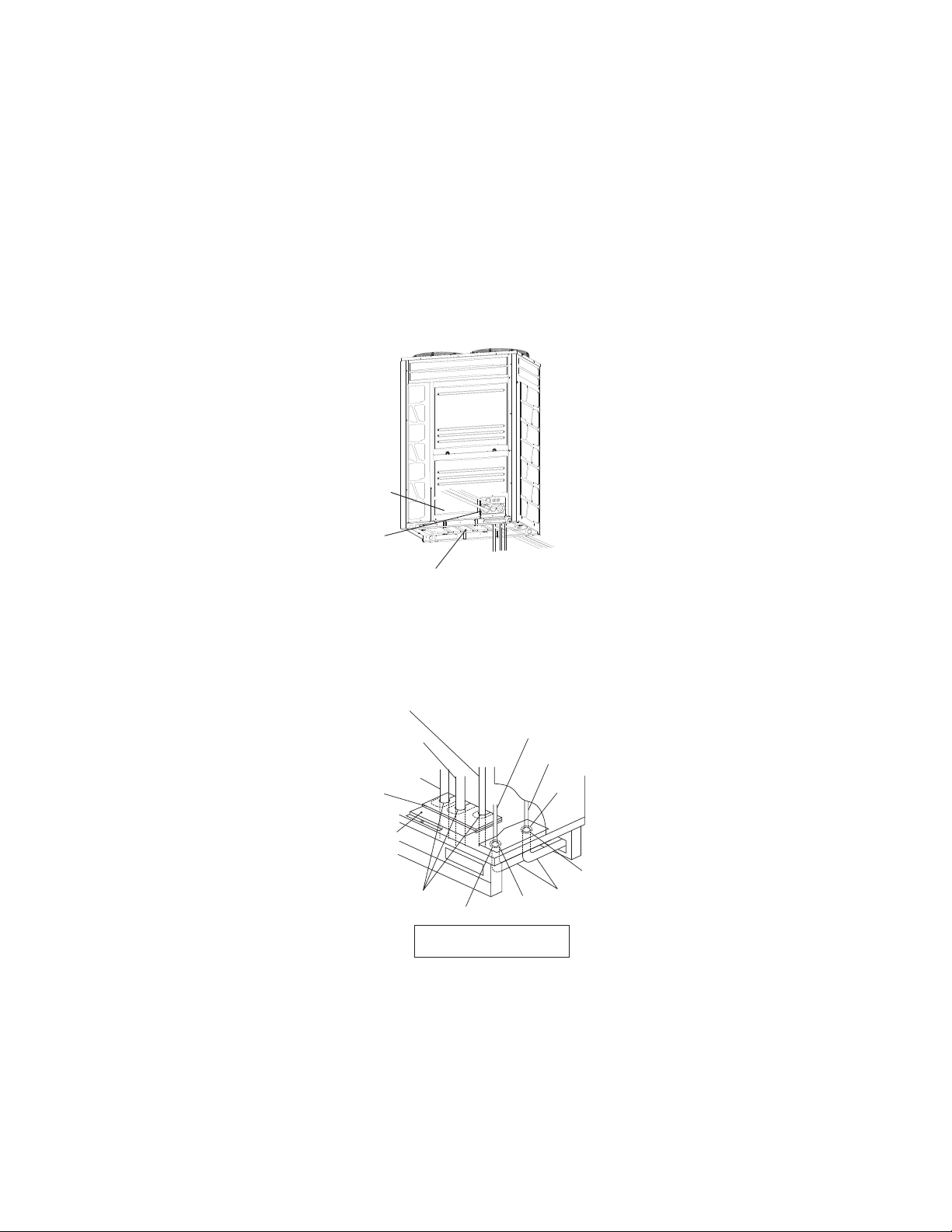
Front Side
Bottom Side
Apply insulation and check
that no clearance exists.
Piping Cover 1
5.4 Piping Connection
Perform piping connection for each outdoor unit.
NOTE:
Ensure that the refrigerant pipes are connected to a unit in the same refrigerant cycle.
Prepare the refrigerant pipe in the field for the piping work.
Piping Direction
Fix the pipes adequately in order to avoid vibration and excessive force to the valve
(1) The pipes are available to connect in three directions from the bottom base.
Front side: gash the piping cover 1 with a boxcutter and connect directly through the service lid at the front unit
Bottom side: connect directly from the piping cover 2 on the bottom base
Rear side: connect from the piping cover 2 on the bottom base, then pass through the bottom base to open a hole
and connect.
●
Rear Side
Bottom Base
Power Supply Wiring
Seal
Seal
Seal
Rubber Bush
Conduit
Transmission Wiring
Liquid Piping
Gas Piping
(High/Low Pressure)
Gas Piping
(Low Pressure)
Rubber Bush
Packing
●
(2) Operation of the stop valve should be performed according to Item 5.4.1.
(3) If the piping is connected from the front side, completely seal the connecting piping with insulation pipe in
order to prevent the ingress of water or snow into the conduit.
(4) If the piping is connected from the bottom or rear side, completely seal the pipe passing through the bottom
of outdoor unit with insulation conduit in order to prevent ingress of water or snow into the conduit.
Loading ...
Loading ...
Loading ...