Loading ...
Loading ...
Loading ...
●
NOTE
By using switch DSW4, the unit starts or stops 10 to 20 seconds after the switch is operated.
Number this outdoor unit to distinguish from other outdoor units for service and maintenance.
And write the number in the box on the right.
Do not touch any other electrical parts when operating switches on the PCB.
6.5 DIP Switch Setting of Outdoor Unit
TURN OFF all power sources before setting.
Without turning OFF, the switches do not work and the contents of the setting are invalid. However, DSW4-
No.1, 2, 4 can work during power source is ON. The mark of “ ” indicates the position of dip switches.
●
NOTES:
• When multiple indoor units are connected to the same single SW BOX, they are controlled with the same operation
mode.
• When multiple indoor units are connected to the same branch of the multi SW BOX, they are controlled with the
same operation mode.
• Do not apply excessive voltage to the communication cable DC5V (non-polarity) between the outdoor unit and the
SW BOX, between the SW BOX and the indoor unit or between SW BOXES.
• Use 2-conductor (at the most) shielded communication cable.
• Connect the communication cable for the outdoor unit to terminals “1” and “2” on TB2 in the SW BOX.
• Connect the communication cable for the cooling only indoor unit or heating only water module to the terminal “1” and
“2” on TB2 in the SW BOX.
• For a SW BOX in the same refrigerant cycle, an electrical power supply can be supplied by one main switch.
• Do not connect the power supply wiring to the terminal block for transmission cable.
• Connect the ground wiring for the outdoor/indoor units and SW BOX. When ground resistance is less than 100 Ω,
ground wiring work should be performed by the qualified electrician.
• Do not run communication cable along with power supply wirings in the SW BOX. Separate communication cables
from the power supply wirings.
• Water module should be connected to an exclusive branch of the SW BOX. .
Setting for Transmitting
It is required to set the outdoor unit Nos., refrigerant cycle Nos. and terminal resistance for this H-NET system.
Setting of Outdoor Unit No.
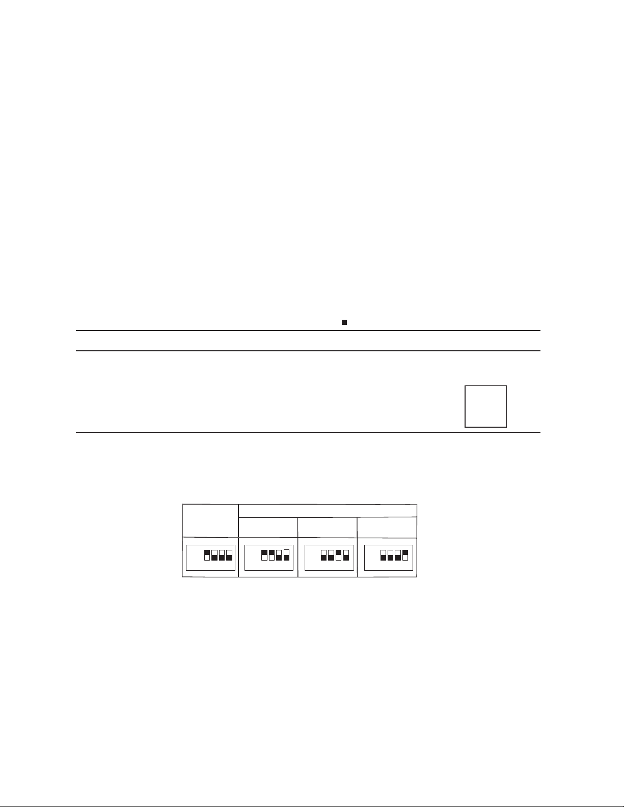
In case of the combination module, set DSW6 as shown below.
●
●
ON
OFF
1 2 3 4
ON
OFF
1 2 3 4
ON
OFF
1 2 3 4
ON
OFF
Basic Unit
(Before Shipment)
Combination Module
(No.0) (Main)
(No.2)
(No.3)
Outdoor Unit A
Outdoor Unit BOutdoor Unit C
1 23
25
●
●
Setting for British Unit
Before shipment, No.4 pin of DSW7 is set at “OFF”, metric units can be used;
set the No.4 pin of DSW7 at “ON” to use the British units.
Loading ...
Loading ...
Loading ...