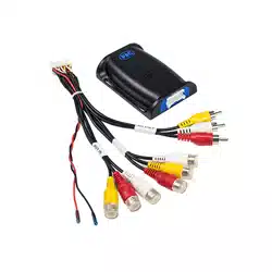
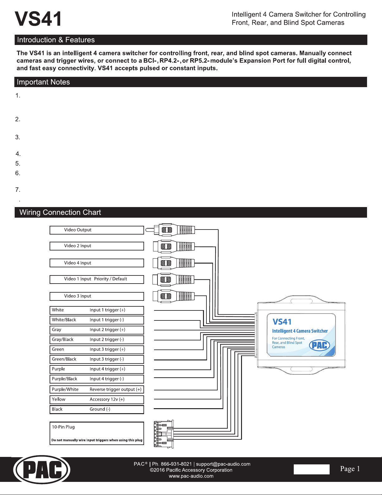
If you are using the VS41 with another PAC interface, such as a BCI-, RP4.2-, or RP5.2-, with an Expansion Port, simply
connect the 10-pin connector into the module. Do not manually wire the positive or negative trigger wires.
The BCI-, RP4.2-, or RP5.2- module will digitally control the VS41 switching operation when connected to the Expansion Port.
The VS41 video output will always default to the signal from Input 1 when none of the input triggers are activated.
This Input is ideal for connecting the rear (reverse) camera.
The VS41 inputs have priority in descending numerical order. For example: If you have Input 3 or 4 triggered, then you
trigger a lower number input (for example Input 2), Input 2 will take priority over the higher numbered Input.
The input triggers can accept either a pulsed or constant input, making them ideal for connecting to a turn signal as a trigger.
The reverse trigger output will provide a 150 mA 12v (+) trigger while any of the input triggers are activated.
Upon deactivation of the last positive or negative trigger, the last video input source and the reverse trigger output will remain
active for an additional 3 seconds. (Not applicable when used with a BCI-, RP4.2-, or RP5.2- interface).
If there is poor video quality after installation of this module, please ensure quality connections on any RCA connections.
Positive Input triggers accept input voltages in the range of 2v to 12v.
8
Connect to the Expansion Port on
BCI-, RP4.2-, or RP5.2- Module.
Rev. 082616