
INSTALLATION GUIDE
BI EU
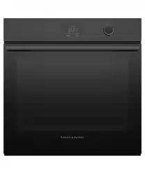
COMBINATION STEAM OVEN
MINIMAL
OS60SMTDB1, OS60SMTDG1
CONTEMPORARY
OS60SDTDX2, OS60SDLX1

2
!
WARNING!
Electric Shock Hazard
Failure to follow this advice may result in
electric shock or death.
• Before carrying out any work on the
electrical section of the appliance, it must
be disconnected from the mains electricity
supply.
• Connection to a good earth wiring system is
absolutely essential and mandatory.
• Alterations to the domestic wiring system
must only be made by a qualified electrician.
!
WARNING!
Fire Hazard
Failure to follow this advice may result in
overheating, burning, and injury.
• Do not use adapters, reducers, or branching
devices to connect this appliance to the
mains power supply.
!
WARNING!
Cut Hazard
Failure to use caution could result in injury.
• Take care: some edges are sharp.
READ AND SAVE THIS GUIDE
WARNING!
To avoid hazard, follow these instructions carefully before installing or using this appliance.
z
Please make this information available to the person installing the appliance—doing so
could reduce your installation costs.
z
This appliance must be installed and connected to the mains power supply only by a
suitably qualified person according to these installation instructions and in compliance
with any applicable local building and electricity regulations. Failure to install the
appliance correctly could invalidate any warranty or liability claims.
z
If the power supply cable is damaged, it must be replaced by the manufacturer, its service
agent or similarly qualified person in order to avoid a hazard.
z
Isolating switch: make sure this oven is connected to a circuit which incorporates an
isolating switch providing full disconnection from the power supply in accordance with the
wiring rules.
z
The oven must be earthed.
z
Do not use adaptors, reducers or branching devices to connect the oven to the mains
electricity supply, as they can cause overheating and burning.
z
The appliance must not be installed behind a decorative door in order to avoid
overheating.
z
Please take extra care not to damage the lower trim of the oven during installation. The
trim is important for correct air circulation and allows the door to open and close without
obstruction. The manufacturer does not accept any responsibility for damage resulting
from incorrect installation.
SAFETY AND WARNINGS

3
Ensure that:
z
the oven cavity is square and level based on the required dimensions
z
the installation will comply with all clearance requirements and applicable standards and
regulations
z
the isolating switch will be easily accessible to the customer with the oven installed
z
the electrician provides sufficient free length of power supply cable to reach from the
bottom rear of the cavity to at least 1.5m in front of the bottom edge of the opening
z
the cable may enter the cavity from the side, top or bottom, but top entry must be at the
rear of the cavity
z
the oven connection socket is outside the cavity if the oven is flush to the rear wall
z
the oven will rest on a surface that can support its weight
z
the height from the floor suits the customer
z
you consult local building authorities and by-laws if in doubt regarding installation
IMPORTANT!
Some environmental factors and cooking habits can cause condensation in and around
the oven during use. To protect surrounding cabinetry from possible damage caused by
frequent or excessive condensation, we recommend moisture-proofing the oven cavity.
Ensure that:
z
the oven door can open fully without obstruction
z
the oven is not sealed into the cabinetry with silicone or glue. This makes future servicing
difficult. Fisher & Paykel will not cover the costs of removing the oven, or of damage
caused by this removal
z
the power supply cable does not touch any hot metal parts
z
the isolating switch is easily accessible to the customer with the oven installed
z
you complete the ‘Installer checklist’ at the end of the installation
z
there is enough clearance for opening and closing operation of the moving control panel.
If, after following the guidance given, correct performance cannot be achieved, please
contact your nearest Fisher & Paykel trained and supported service technician, Customer
Care, or contact us through our website fisherpaykel.com
INSTALLATION CONSIDERATIONS
BEFORE INSTALLATION AFTER INSTALLATION
4
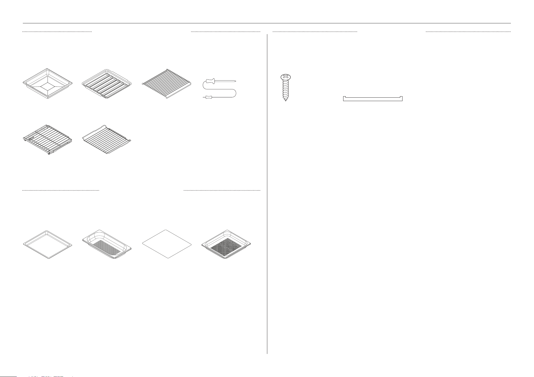
COMPONENTS
STANDARD ACCESSORY KIT INSTALLATION KIT
Part No. 580836
Supplied with all models.
Part No. 580720
Supplied with all models.
Supplied with all models.
Large solid dish Large perforated dishSmall perforated dish
Tray
Screws (2) Cabinetry trim (1)
STEAM ACCESSORY KIT
Roast dish Grid Grill rack
Full extension sliding shelf
Food probe
Step down wire shelf
5
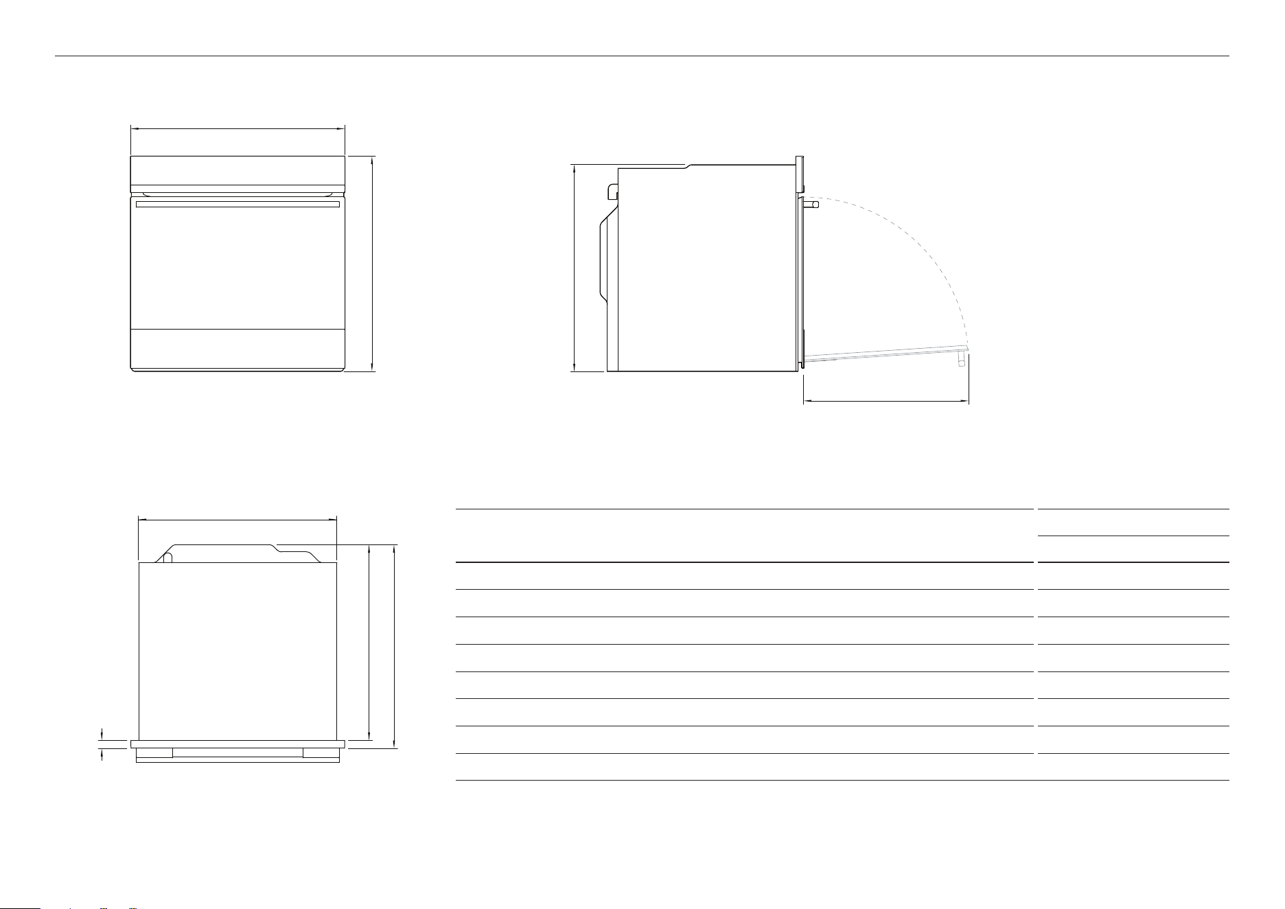
PRODUCT DIMENSIONS
OS60SDT
MM
A Overall height of oven 598
B Overall width of oven 596
C Overall depth of oven (excluding handle and dials) 566
D Height of chassis 575
E Width of chassis 556
F Depth of chassis 545
G Depth of oven frame and control panel (between front of chassis and front of oven door) 21
H Depth of oven door when fully open (measured from front of control panel) 460
PRODUCT DIMENSIONS
a
c
f
g
d
e
B
h
FRONT
PLAN
PROFILE
6
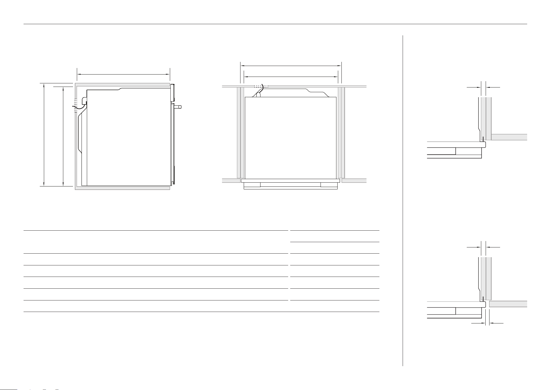
CABINETRY DIMENSIONS
OS60SDT
MM
A Minimum inside width of cavity
560
B Overall width of cabinetry
600
C Minimum inside height of cavity
580
D Overall height of cabinetry
600
E Minimum inside depth of cavity
550
If installing a cooktop above the oven, ensure adequate clearance is provided as per the cooktop manufacturer’s instructions.
CABINETRY DIMENSIONS
PROUD INSTALL
FLUSH INSTALL
16-20mm
16-20mm
2mm
PROFILE PLAN
e
b
a
D C
Ensure a 5mm minimum clearance is maintained between the top of the oven chassis and the cabinetry. Ensure the oven is not bearing
any weight from cabinetry or products installed above.
7
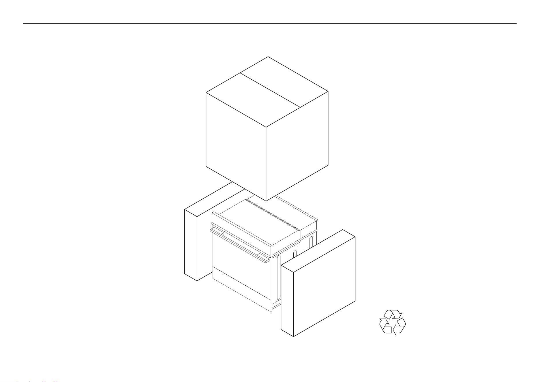
Remove the packaging from the side
and accessories box from the top of
the oven, and set aside.
Recycle responsibly
DISCARD PACKAGING RESPONSIBLY
8
z
This oven must be connected to the mains power supply only by a suitably
qualified person.
z
This oven must be earthed.
Before connecting the oven to the mains power supply, check that:
the domestic wiring system is suitable for the power drawn by the oven (as specified on
the rating plate).
the voltage corresponds to the value given on the rating plate.
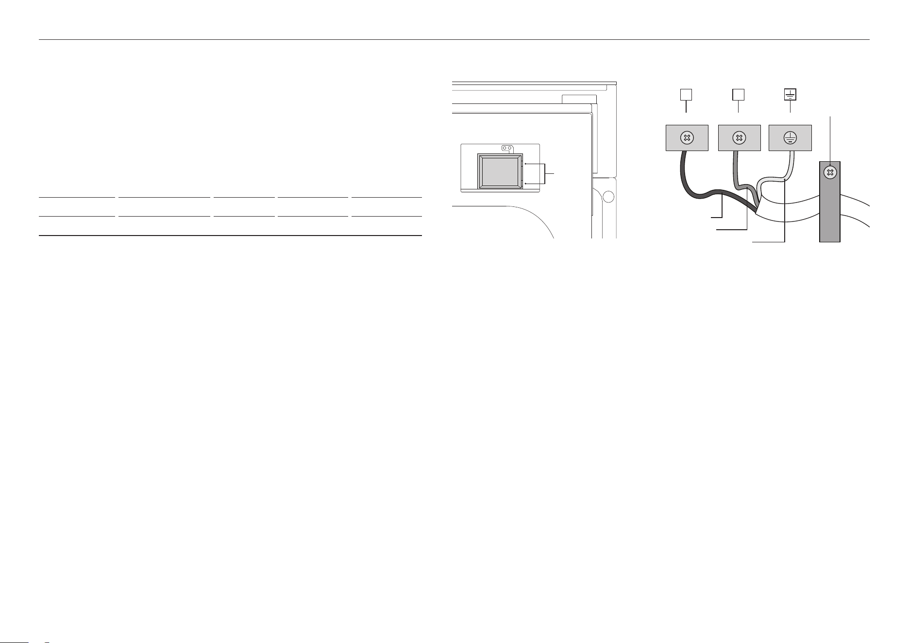
CONNECT THE OVEN TO THE MAINS SUPPLY
L
1
N(L
2
) E
L
1
N(L
2
) E
MODEL CODE MAX POWER (W) HZ VOLTAGE (V) AMPS (A)
OS60SDT 2800 - 3300 50 - 60 220 - 240 V~ 12.8 - 13.8
Brown (Live)
Blue (Neutral)
Green & Yellow (Earth)
Ensure cable
clamp is
tightened
Unclip
and lift
9
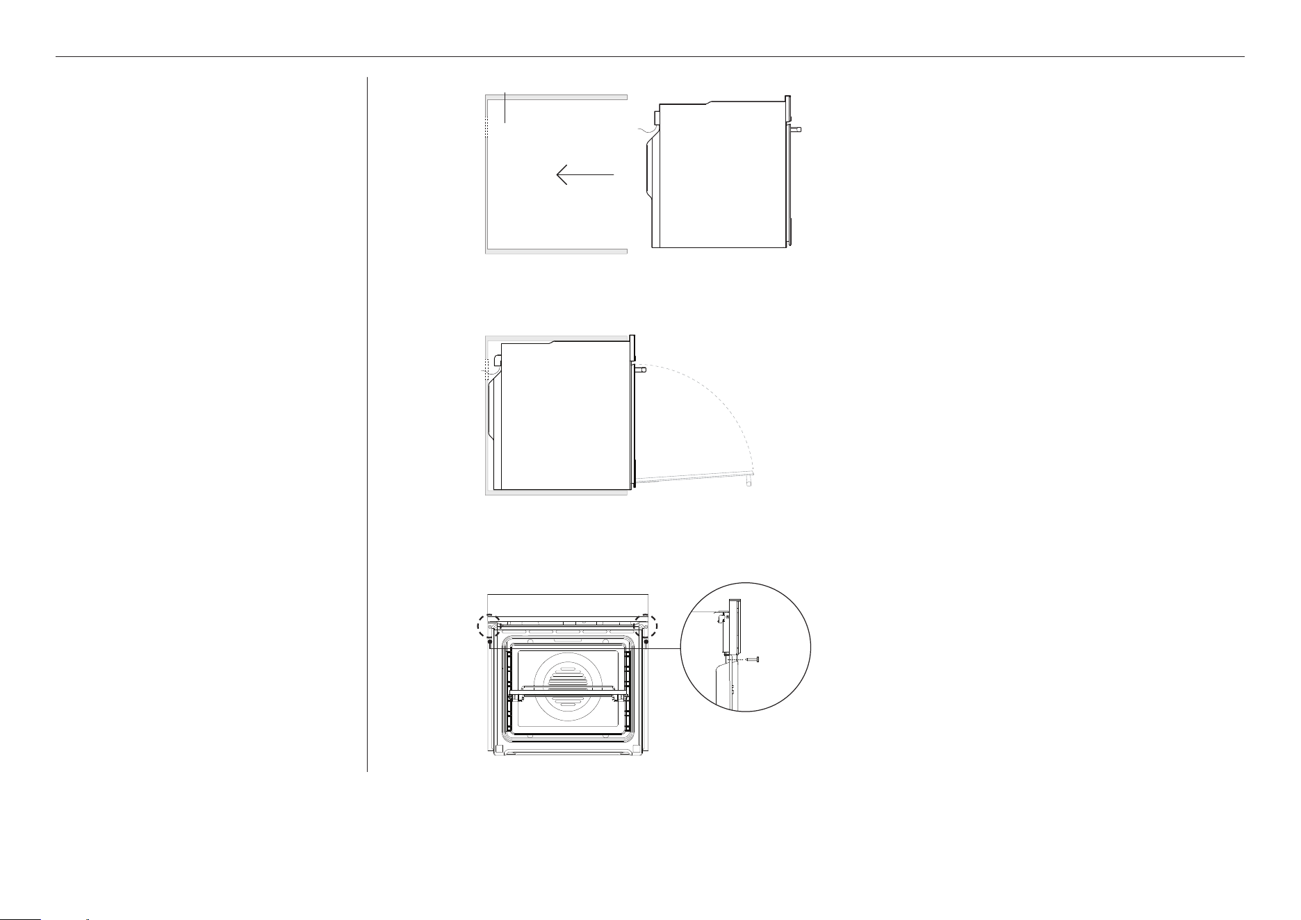
SECURE THE OVEN TO THE CABINETRY
z
Do not lift the oven by the door handle.
z
Do not over-tighten the screws.
z
Do not seal the oven into the cabinetry
with silicone or glue. This makes future
servicing difficult. Fisher & Paykel will
not cover the costs of removing the
oven, or of damage caused by this
removal.
1
2
3
cavity
Use the supplied screws to secure the oven to the
cabinetry.
Open the oven door fully.
Mark and pre-drill the screw holes to the sides of the
cabinetry.
For dark cabinetry, the supplied trim can be used to
enhance clashing finish. To install, remove the trim
adhesive and press to secure to cavity.
Position the oven in the prepared cavity.

10
Complete and keep for safe reference:
Model
Serial No.
Purchase Date
Purchaser
Dealer Address
Installer’s Name
Installer’s Signature
Installation Company
Installation Date
INSTALLER CHECKLIST
TO BE COMPLETED BY THE INSTALLER
F Ensure the oven is level and securely fitted to the cabinetry.
F Open the oven door slowly until it is fully open and check there is adequate
clearance between the bottom of the door and the lower trim.
This is to ensure correct air circulation. Should the lower trim become damaged,
straighten the trim and ensure the oven door opens fully without obstruction.
F Ensure all internal packaging (including the circular yellow packing retainers
holding the accessory box in place) is removed.
F Ensure all oven vents and openings are clear and free of any obstruction or
damage.
Failure to make sure all oven vents are clear may result in poor product
performance.
F Ensure the isolating switch is accessible by the customer.
TEST OPERATION:
F Turn on the oven. The display should light up.
F Set the clock following the instructions in the ‘User guide’.
F Turn on the moving control panel. Remove protective wrap from control panel
arms. Check clearance during opening and closing operation.
F Set the oven to BAKE at 50
o
C. The cavity light should turn on inside the oven
cavity and air should blow out from the vent at the top of the oven. After five
minutes, open the oven door. The air inside should feel warm. Turn the oven off.
F Demonstrate the basic operation to the customer.


41405A 09.2
FISHERPAYKEL.COM
© Fisher & Paykel Appliances 2023. All rights reserved.
The models shown in this guide may not be available in all markets
and are subject to change at any time.
The product specifications in this guide apply to the specific products and
models described at the date of issue. Under our policy of continuous product
improvement, these specifications may change at any time.
For current details about model and specification availability in your country,
please go to our website or contact your local Fisher&Paykel dealer.