
PLANNING GUIDE
HANDLELESS OVENS AND COMPANIONS, 60CM
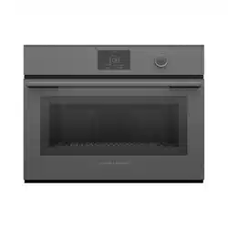
OVEN | OB60SMPTNB1, OB60SMPNG1
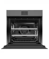
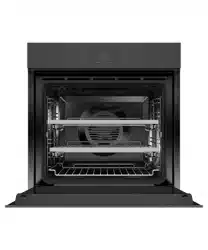
STEAM OVEN | OS60SMTNB1, OS60SMTNG1, OS60NMTNB1, OS60NMTNG1
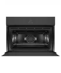
COMBINATION MICROWAVE OVEN | OM60NMTNG1, OM60NMTNB1
BUILT-IN COFFEE MAKER | EB60MSB1, EB60MSG1
WARMING DRAWER | WB60SMB1-SET, WB60SMG1-SET, WB60SMTB1-SET
VACUUM SEAL DRAWER | VB60SMB1-SET, VB60SMG1-SET

© FISHER & PAYKEL LIMITED 2024 PAGE 290003353D PLANNING GUIDE COOKING - VERSION D - APRIL 2024
PLANNING GUIDE | HANDLELESS OVENS AND COMPANIONS, 60CM
This comprehensive Planning Guide provides you with the framework and tools to achieve your desired design outcome with Fisher & Paykel appliances. In this guide, you will
find a range of conceptual, detailed and dimensional product information to bring your ideas to life and create spaces that truly reflect your vision.
CONCEPT DESIGN PAGE DEVELOPED AND DETAILED DESIGN PAGE PAGE
CONTENTS
The models shown in this Planning Guide may not be available in all markets and are subject to change at any time. Product specifications may vary from those shown. This Planning Guide should not be used as installation guidance for any
product. Further information is required to safely and correctly install the products featured here. Specific installation guidance will be available on our website fisherpaykel.com
Design Choices
Ovens and Companions - ALL MODELS 4
Configurations - ALL MODELS 5
Overview - ALL MODELS 6
Specification Guides
Oven 8
Combination Steam Oven 9
Combination Steam Oven 10
Combination Microwave Oven 11
Built-in Coee Maker 12
Warming Drawer, Tall 13
Warming Drawer 14
Vacuum Seal Drawer 15
Dimensions - ALL MODELS 16
Power, Weight and Capacity - ALL MODELS 17
Data Sheets
Oven 19
Combination Steam Oven 20
Combination Steam Oven 21
Combination Microwave Oven 22
Built-in Coee Maker 23
Warming Drawer, Tall 24
Warming Drawer 25
Vacuum Seal Drawer 26
Planning Considerations
Cabinetry Preparation - ALL MODELS 28
Configurations - ALL MODELS 29
Oven 30
Combination Steam Oven 31
Combination Steam Oven 32
Combination Microwave Oven 33
Built-in Coee Maker 34
Warming Drawer, Tall 35
Warming Drawer 36
Vacuum Seal Drawer 37
Services
Power Cord Length and Location - COMPANIONS 39
Power Cord Length and Location - OVENS 40
i
i

© FISHER & PAYKEL LIMITED 2024 PAGE 390003353D PLANNING GUIDE COOKING - VERSION D - APRIL 2024
DESIGN CHOICES
Design Choices
© FISHER & PAYKEL LIMITED 2024 PAGE 490003353D PLANNING GUIDE COOKING - VERSION D - APRIL 2024
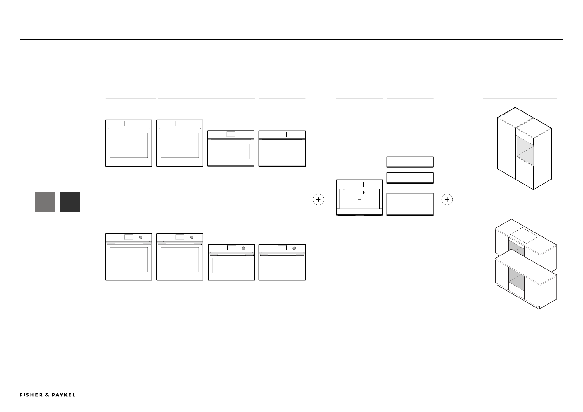
+ +
Installation in wall
Installation
under-bench
Grey
Glass
HANDLELESS FAMILY
DIAL AND HANDLE FAMILY
OVENS STEAM MICROWAVES COFFEE MAKER DRAWERS INSTALLATION OPTIONS
COLOUR
Black
Glass
DESIGN CHOICES | OVENS AND COMPANIONS, 60CM
*Note: Warming Drawer Tall only available in
Black Glass finish
*
ALL MODELS
Ovens and Companions - ALL MODELS
The models shown in this Planning Guide may not be available in all markets and are subject to change at any time. Product specifications may vary from those shown. This Planning Guide should not be used as installation guidance for any
product. Further information is required to safely and correctly install the products featured here. Specific installation guidance will be available on our website fisherpaykel.com
<< CONTENTS

© FISHER & PAYKEL LIMITED 2024 PAGE 590003353D PLANNING GUIDE COOKING - VERSION D - APRIL 2024
STACKED INSTALLATION GRID INSTALLATIONROW INSTALLATION CONSIDERATIONS
Different configurations possible,
considerations are height,
colour, dial and handle or handleless.
Note: Stack Height is overall product height with minimum clearances above appliance front panel to upper cabinetry front panel or appliance.
Stack Height
600mm
Stack Height
1060mm
Stack Height
600mm
Stack Height
1200mm
Stack Height
1060mm
Stack Height
1210mm
ALL MODELSDESIGN CHOICES | CONFIGURATIONS, 60CM
Configurations - ALL MODELS
The models shown in this Planning Guide may not be available in all markets and are subject to change at any time. Product specifications may vary from those shown. This Planning Guide should not be used as installation guidance for any
product. Further information is required to safely and correctly install the products featured here. Specific installation guidance will be available on our website fisherpaykel.com
<< CONTENTS
The models shown in this Planning Guide may not be available in all markets and are subject to change at any time. Product specifications may vary from those shown. This Planning Guide should not be used as installation guidance for any
product. Further information is required to safely and correctly install the products featured here. Specific installation guidance will be available on our website fisherpaykel.com
© FISHER & PAYKEL LIMITED 2024 PAGE 690003353D PLANNING GUIDE COOKING - VERSION D - APRIL 2024
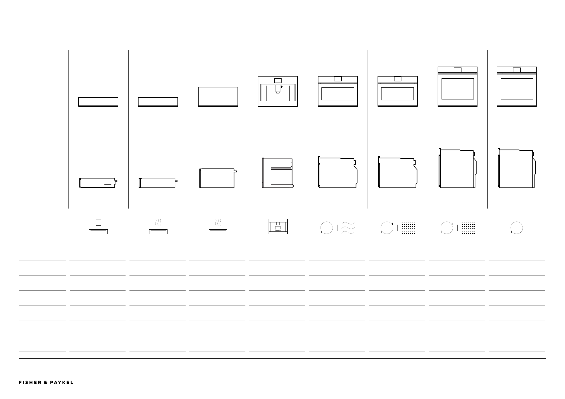
FRONT ELEVATION
SIDE ELEVATION
DESIGN CHOICES | OVERVIEW, 60CM
VACUUM SEAL DRAWER WARMING DRAWER WARMING DRAWER TALL BUILT-IN COFFEE MAKER COMBINATION MICROWAVE
OVEN
COMBINATION STEAM
OVEN
COMBINATION STEAM
OVEN
OVEN
Series Series 9 Series 9 Series 9 Series 9 Series 9 Series 9 Series 11 Series 9
Model Codes
Black Glass
VB60SMB1-SET WB60SMB1-SET WB60SMTB1-SET EB60MSB1 OM60NMTNB1 OS60NMTNB1 OS60SMTNB1 OB60SMPTNB1
Model Codes
Grey Glass
VB60SMG1-SET WB60SMG1-SET - EB60MSG1 OM60NMTNG1 OS60NMTNG1 OS60SMTNG1 OB60SMPTNG1
Interface - - - 4.3" Touchscreen 5" Touchscreen 5" Touchscreen 5" Touchscreen 5" Touchscreen
Overall Product Heights 140mm 140mm 290mm 458mm 458mm 458mm 598mm 598mm
Front Panel Thickness 20mm 20mm 20mm 20mm 20mm 20mm 20mm 20mm
ALL MODELS
Overview - ALL MODELS
<< CONTENTS

© FISHER & PAYKEL LIMITED 2024 PAGE 790003353D PLANNING GUIDE COOKING - VERSION D - APRIL 2024
SPECIFICATION GUIDE
Specification Guides

The models shown in this Planning Guide may not be available in all markets and are subject to change at any time. Product specifications may vary from those shown. This Planning Guide should not be used as installation guidance for any
product. Further information is required to safely and correctly install the products featured here. Specific installation guidance will be available on our website fisherpaykel.com
© FISHER & PAYKEL LIMITED 2024 PAGE 890003353D PLANNING GUIDE COOKING - VERSION D - APRIL 2024
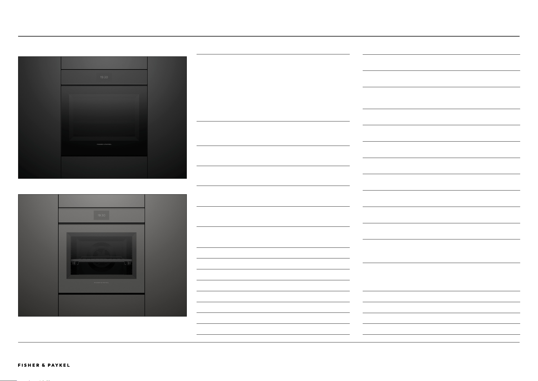
OVERVIEW
Designed to complement our Minimal style appliances, this
handleless oven oers a sleek, uninterrupted aesthetic that
moves beyond traditional oven doors. Perfect for true
handleless kitchen designs, it provides a streamlined look
and ensures a continuous flow across kitchen surfaces. With
a generous 85L capacity, 16 functions, and self-cleaning, its
guided touchscreen ensures perfect results with ease.
PRODUCTS
OB60SMPTNB1 - Black Glass
Oven, 60cm, 16 Function, Self-cleaning
OB60SMPTNG1 - Grey Glass
Oven, 60cm, 16 Function, Self-cleaning
FEATURES
1
Handleless oven design ensures smooth, uninterrupted
lines in kitchen cabinetry for a cohesive look
2 Designed to complement our Minimal style kitchen
appliances
3 Effortlessly open and close the oven with a gentle press of
a button, ensuring convenience and smooth operation in
the kitchen
4 Available in both elegant black glass and subtle grey glass
finishes
5 Designed to match companion products such as Warming
Drawers
6 Guided touchscreen cooking offers helpful tips for
different food types
7 Generous 85L total capacity
8 16 oven functions including Pastry Bake, Roast, and Air Fry
9 Self-cleaning pyrolytic function breaks down food residue
for an easy clean
"0 Even heat circulation with AeroTech™, ideal for multi-shelf
cooking
"1 Includes a Wired Temperature Sensor for real-time
monitoring of cooking temperatures
"2 Voice-activated oven door provides hands-free control,
compatible with Google's voice assistant via the
SmartHQ™ appmonitoring of cooking temperatures*
*Not available in all markets
SPECIFICATION GUIDE | OVEN, 60CM
OB60SMPTNB1
OB60SMPTNG1
OB60SMPTNB1, OB60SMPTNG1
SERIES & STYLE
Series 9
Minimal
ACCESORIES
5
Wired Temperature Sensor
6 Flat Brushed Baking Tray
7 Pyrolytic Proof Shelf Runners
ACCESSORIES
1
Full Extension Sliding Shelf
2 Grill Rack
3 Smokeless Grill Tray
4 Roasting Dish
5 Step Down Wire Shelf
Oven
<< CONTENTS
The models shown in this Planning Guide may not be available in all markets and are subject to change at any time. Product specifications may vary from those shown. This Planning Guide should not be used as installation guidance for any
product. Further information is required to safely and correctly install the products featured here. Specific installation guidance will be available on our website fisherpaykel.com
© FISHER & PAYKEL LIMITED 2024 PAGE 990003353D PLANNING GUIDE COOKING - VERSION D - APRIL 2024
SPECIFICATION GUIDE | COMBINATION STEAM OVEN, 60CM OS60SMTNB1, OS60SMTNG1
OVERVIEW
The cornerstone of our collection, our handleless
Combination Steam Oven oers a sleek, uninterrupted
aesthetic that moves beyond traditional oven doors. Perfect
for true handleless kitchen designs, it provides a
streamlined look and ensures a continuous flow across
kitchen surfaces. With 23 functions and a sophisticated
balance of full steam and steam assist options at various
temperatures, this oven ensures perfect results.
PRODUCTS
OS60SMTNB1 - Black Glass
Combination Steam Oven, 60cm, 23 Function
OS60SMTNG1 - Grey Glass
Combination Steam Oven, 60cm, 23 Function
FEATURES
1
Handleless oven design ensures smooth, uninterrupted lines
in kitchen cabinetry for a cohesive look
2 Designed to complement our Minimal style kitchen
appliances
3 Effortlessly open and close the oven with a gentle press of
a button, ensuring convenience and smooth operation in the
kitchen
4 Available in both elegant black glass and subtle grey glass
finishes
5 Perfectly pairs with companion products such as Vacuum
Seal Drawers
6 Guided touchscreen cooking offers helpful tips for different
food types
7 True temperature precision with three levels of steam with
convection
8 23 oven functions including Steam, Sous Vide, Air Fry and
Crisp Regenerate
9 Help reduce food waste by rejuvenating leftovers with
steam for fresh-tasting roasts, and risottos and more
"0 Even heat circulation with AeroTech™, ideal for multi-shelf
cooking
"1 Includes a Wired Temperature Sensor for real-time
monitoring of cooking temperatures
"2 Voice-activated oven door provides hands-free control,
compatible with Google's voice assistant via the SmartHQ™
appmonitoring of cooking temperatures*
*Not available in all markets
SERIES & STYLE
Series 11
Minimal
ACCESORIES
9
Small Perforated Steam Dish
"0 Roasting Dish
"1 Smokeless Grill Tray
"2 Wired Temperature Sensor
ACCESSORIES
1
Chromed Shelf Runners
2 2x Descale Solutions
3 Flat Brushed Baking Tray
4 2x Full Extension Sliding Shelves
5 Grill Rack
6 Large Steam Dish
7 Step Down Wire Shelf
8 Large Perforated Steam Dish
OS60SMT NB1
OS60SMTNG1
Combination Steam Oven
<< CONTENTS

The models shown in this Planning Guide may not be available in all markets and are subject to change at any time. Product specifications may vary from those shown. This Planning Guide should not be used as installation guidance for any
product. Further information is required to safely and correctly install the products featured here. Specific installation guidance will be available on our website fisherpaykel.com
© FISHER & PAYKEL LIMITED 2024 PAGE 1090003353D PLANNING GUIDE COOKING - VERSION D - APRIL 2024
OVERVIEW
The cornerstone of our collection, our handleless
Combination Steam Oven oers a sleek, uninterrupted
aesthetic that moves beyond traditional oven doors. Perfect
for true handleless kitchen designs, it provides a
streamlined look and ensures a continuous flow across
kitchen surfaces. With 23 functions and a sophisticated
balance of full steam and steam assist options at various
temperatures, this oven ensures perfect results.
PRODUCTS
OS60NMTNB1 - Black Glass
Combination Steam Oven, 60cm, 23 Function
OS60NMTNG1 - Grey Glass
Combination Steam Oven, 60cm, 23 Function
FEATURES
1
Handleless oven design ensures smooth, uninterrupted
lines in kitchen cabinetry for a cohesive look
2 Designed to complement our Minimal style kitchen
appliances
3 Effortlessly open and close the oven with a gentle press of
a button, ensuring convenience and smooth operation in
the kitchen
4 Available in both elegant black glass and subtle grey glass
finishes
5 Perfectly pairs with companion products such as Vacuum
Seal Drawers
6 Guided touchscreen cooking offers helpful tips for
different food types
7 True temperature precision with three levels of steam with
convection
8 23 oven functions including Steam, Sous Vide, Air Fry and
Crisp Regenerate
9 Help reduce food waste by rejuvenating leftovers with
steam for fresh-tasting roasts, and risottos and more
"0 Even heat circulation with AeroTech™, ideal for multi-shelf
cooking
"1 Includes a Wired Temperature Sensor for real-time
monitoring of cooking temperatures
"2 Voice-activated oven door provides hands-free control,
compatible with Google's voice assistant via the
SmartHQ™ appmonitoring of cooking temperatures*
*Not available in all markets
SPECIFICATION GUIDE | COMBINATION STEAM OVEN, 60CM OS60NMTNB1, OS60NMTNG1
SERIES & STYLE
Series 9
Minimal
ACCESORIES
9
Roasting Dish
"0 Wired Temperature Sensor
ACCESSORIES
1
Chromed Shelf Runners
2 2x Descale Solutions
3 Flat Brushed Baking Tray
4 Grill Rack
5 Large Steam Dish
6 Wire Shelf
7 Large Perforated Steam Dish
8 Small Perforated Steam Dish
OS60NMTNB1
OS60NMTNG1, paired with Warming Drawer WB60SMG1-SET
Combination Steam Oven
<< CONTENTS
The models shown in this Planning Guide may not be available in all markets and are subject to change at any time. Product specifications may vary from those shown. This Planning Guide should not be used as installation guidance for any
product. Further information is required to safely and correctly install the products featured here. Specific installation guidance will be available on our website fisherpaykel.com
© FISHER & PAYKEL LIMITED 2024 PAGE 1190003353D PLANNING GUIDE COOKING - VERSION D - APRIL 2024
SPECIFICATION GUIDE | COMBINATION MICROWAVE OVEN, 60CM OM60NMTNB1, OM60NMTNG1
Combination Microwave Oven
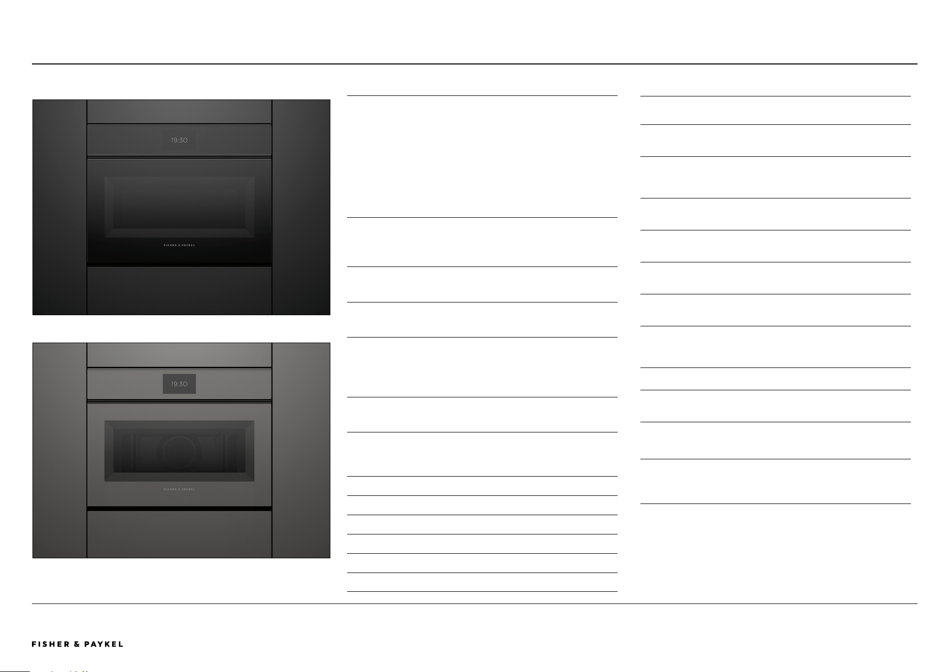
OVERVIEW
Experience the speed of microwave cooking with the
versatility of a convection oven in a compact companion
model. Designed to complement our Minimal style
appliances, this handleless microwave oven features a sleek,
seamless look that moves away from traditional oven door
designs. Its compact size and 49L capacity provide
convenient placement and ample space for a variety of
dishes, ensuring perfect results.
PRODUCTS
OM60NMTNB1 - Black Glass
Combination Microwave Oven, 60cm, 22 Function
OM60NMTNG1 - Grey Glass
Combination Microwave Oven, 60cm, 22 Function
FEATURES
1
Handleless oven design ensures smooth, uninterrupted
lines in kitchen cabinetry for a cohesive look
2 Compact 60cm width means this microwave oven can be
placed almost anywhere
3 Effortlessly open and close the oven with a gentle press of
a button, ensuring convenience and smooth operation in
the kitchen
4 Designed to complement our Minimal style kitchen
appliances
5 Available in both elegant black glass and subtle grey glass
finishes
6 Guided touchscreen cooking offers helpful tips for
different food types
7 22 functions, including four microwave-only, 14 traditional
oven, and four combination settings
8 Combi microwave versatility for quick, even heating across
a variety of dishes, ensuring perfect interior cooking with
crisp exteriors
9 Generous 49L capacity, with four shelf positions
"0 CoolTouch door is safe to touch from the outside,
protecting hands and surrounding cabinetry
"1 Includes a Wired Temperature Sensor for real-time
monitoring of cooking temperatures
"2 Voice-activated oven door provides hands-free control,
compatible with Google's voice assistant via the
SmartHQ™ appmonitoring of cooking temperatures*
*Not available in all markets
SERIES & STYLE
Series 9
Minimal
ACCESSORIES
1
Chromed Shelf Runners
2 Glass Tray
3 Step Down Wire Shelf
4 Wire Shelf
5 Wired Temperature Sensor
6 Grill Rack
OM60NMTNB1
OM60NMTNG1
<< CONTENTS
The models shown in this Planning Guide may not be available in all markets and are subject to change at any time. Product specifications may vary from those shown. This Planning Guide should not be used as installation guidance for any
product. Further information is required to safely and correctly install the products featured here. Specific installation guidance will be available on our website fisherpaykel.com
© FISHER & PAYKEL LIMITED 2024 PAGE 1290003353D PLANNING GUIDE COOKING - VERSION D - APRIL 2024
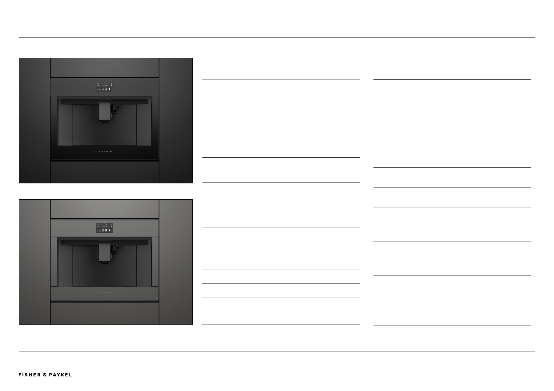
OVERVIEW
The Built-in Coee Maker features a stylish finish and can
be installed in multiple configurations to suit kitchen design
and preference. With 13 beverage options, our Coee Maker
is designed to consistently pour delicious coee – from Flat
White to Latte or Americano. Favourite coee styles are
memorised for a fast brew with the push of a button. A
programmable timer turns the Coee Maker on at the ideal
time each day, while the conical burr grinder delivers a
consistent grind for a perfect coee.
PRODUCTS
EB60MSB1 - Black Glass
Built-in Coffee Maker, 60cm
EB60MSG1 - Grey Glass
Built-in Coffee Maker, 60cm
SPECIFICATION GUIDE | BUILT-IN COFFEE MAKER, 60CM
Built-in Coee Maker
Built-in Coee Maker EB60MSB1, paired with Warming Drawer WB60SMB1-SET
Built-in Coee Maker EB60MSG1, paired with Warming Drawer WB60SMG1-SET
EB60MSB1, EB60MSG1
SERIES & STYLE
Series 9
Minimal
ACCESSORIES
1
Thermal milk jug (0.5L)
2 Water filter
3 Coffee spoon
4 Extractable steam outlet
5 Descaling agent bottle
FEATURES
1
Designed to pair perfectly with 60cm ovens and
companion products
2 Stylish stainless steel finish
3 Install in multiple configurations to suit your kitchen
design
4 Intuitive touch display
5 13 functions to suit any taste and selection – from
Espresso to Latte
6 Programmable timer turns on the Coffee Maker at the
ideal time each day
7 Favourite coffee types are memorised and stored in
custom profiles
8 Stainless steel conical burr grinder with 13 coarseness
positions
9 15 bar pump pressure
"0 Self-cleaning function and easy to empty coffee grounds
container and drip tray
"1 2.4L water tank capacity
<< CONTENTS
The models shown in this Planning Guide may not be available in all markets and are subject to change at any time. Product specifications may vary from those shown. This Planning Guide should not be used as installation guidance for any
product. Further information is required to safely and correctly install the products featured here. Specific installation guidance will be available on our website fisherpaykel.com
© FISHER & PAYKEL LIMITED 2024 PAGE 1390003353D PLANNING GUIDE COOKING - VERSION D - APRIL 2024
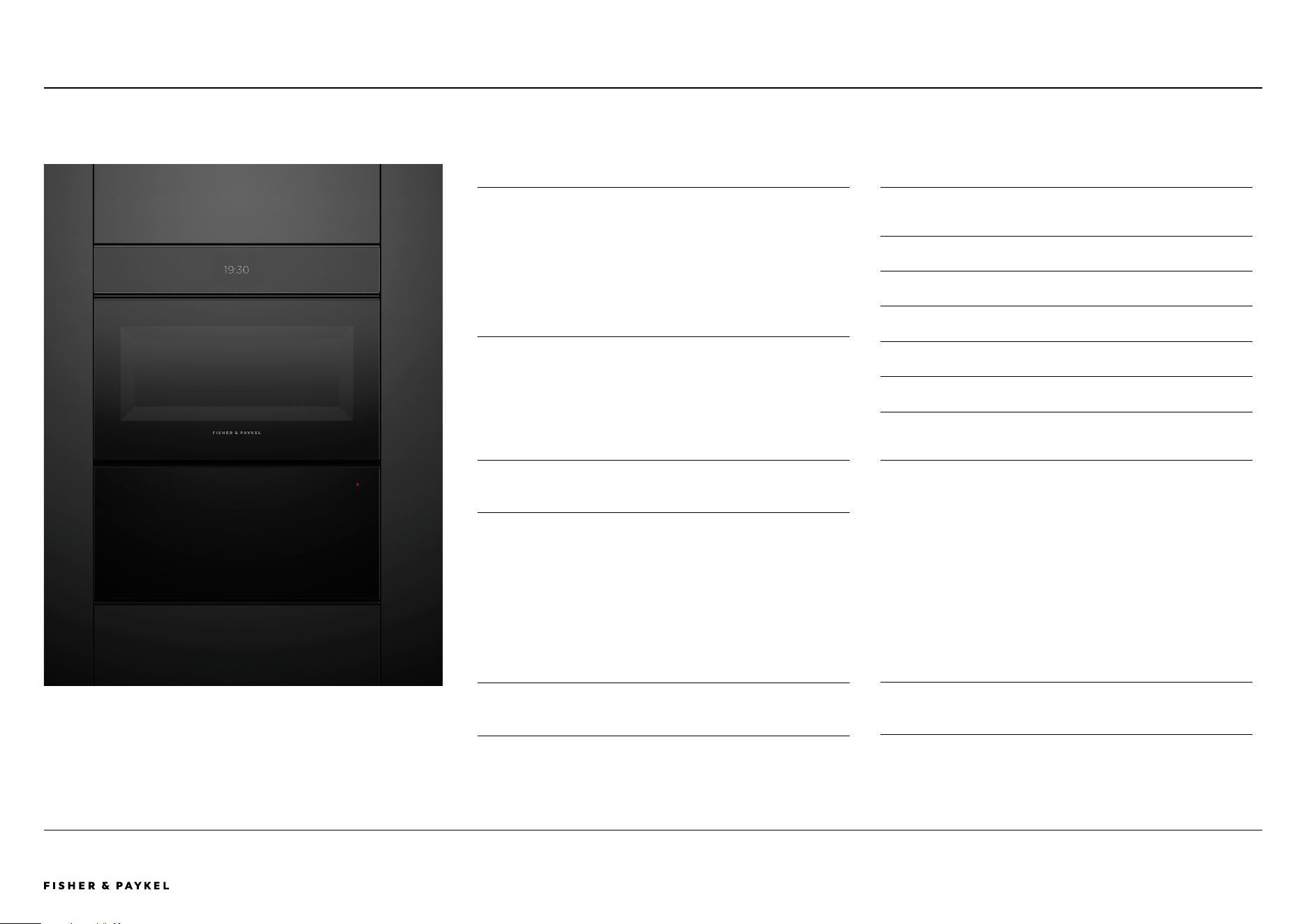
OVERVIEW
Designed to complement our Minimal style ovens, these
warming drawers are handle-free, and push-to-open for a
coherent, considered look. Beautiful to use, with capacitive
touch controls and six tailored functions for warming,
proofing, dehydrating and slow cook. Pair with other
companion products to create a kitchen suite for every
need.
PRODUCTS
WB60SMTB1-SET - Black Glass
Warming Drawer, 60cm, Tall, Panel Ready*
*This model comes with an accessory door panel, and is not suitable for use
with a custom door panel
SPECIFICATION GUIDE | WARMING DRAWER, 60CM, TALL
Warming Drawer, Tall
Warming Drawer WB60SMTB1-SET, paired with Steam Oven OS60NMTNB1
WB60SMTB1-SET
SERIES & STYLE
Series 9
Minimal
FEATURES
1
Seamless pairing with our Minimal style ovens and other
companion products
2 Push-to-open drawer
3 Easy-to-use capacitive touch controls
4 Automatic timing and switch-off functionality
5 Easy-to-clean, smooth-glass base
6 Room for 16 standard-sized place settings
7 Versatile with six tailored programmes for warming,
proofing, dehydrating and slow cook
ACCESSORIES
1
Accessory rack for optimising space
<< CONTENTS

The models shown in this Planning Guide may not be available in all markets and are subject to change at any time. Product specifications may vary from those shown. This Planning Guide should not be used as installation guidance for any
product. Further information is required to safely and correctly install the products featured here. Specific installation guidance will be available on our website fisherpaykel.com
© FISHER & PAYKEL LIMITED 2024 PAGE 1490003353D PLANNING GUIDE COOKING - VERSION D - APRIL 2024
OVERVIEW
Designed to complement our Minimal style ovens, these
warming drawers are handle-free, and push-to-open for a
coherent, considered look. Beautiful to use, with capacitive
touch controls and six tailored functions for warming,
proofing, dehydrating and slow cook. Pair with other
companion products to create a kitchen suite for every
need.
PRODUCTS
WB60SMB1-SET - Black Glass
Warming Drawer, 60cm, Panel Ready*
WB60SMG1-SET - Grey Glass
Warming Drawer, 60cm, Panel Ready*
*This model comes with an accessory door panel, and is not suitable for use
with a custom door panel
SPECIFICATION GUIDE | WARMING DRAWER, 60CM
Warming Drawer
Warming Drawer WB60SMB1-SET, paired with Steam Oven OS60NMTDB1
Warming Drawer WB60SMG1-SET, paired with Steam Oven OS60NMTDG1
WB60SMB1-SET, WB60SMG1-SET
SERIES & STYLE
Series 9
Minimal
FEATURES
1
Seamless pairing with our Minimal style ovens and other
companion products
2 Push-to-open drawer
3 Easy-to-use capacitive touch controls
4 Easy-to-clean, smooth-glass base
5 Room for six standard-sized place settings
6 Automatic timing, switch-off functionality
7 Interior LED lighting
8 Versatile with six tailored programmes for warming,
proofing, dehydrating and slow cook
<< CONTENTS

The models shown in this Planning Guide may not be available in all markets and are subject to change at any time. Product specifications may vary from those shown. This Planning Guide should not be used as installation guidance for any
product. Further information is required to safely and correctly install the products featured here. Specific installation guidance will be available on our website fisherpaykel.com
© FISHER & PAYKEL LIMITED 2024 PAGE 1590003353D PLANNING GUIDE COOKING - VERSION D - APRIL 2024
OVERVIEW
Designed to match our Minimal style appliances, the
Vacuum Seal Drawer is the ideal companion for our
Combination Steam Oven. Prepares food for sous vide
cooking, or vacuum sealing for marinating, food storage and
portioning and resealing. Beautiful to use, with capacitive
touch controls, these drawers deliver the performance to
achieve perfect results.
PRODUCTS
VB60SMB1-SET - Black Glass
Vacuum Seal Drawer, 60cm, Panel Ready*
VB60SMG1-SET - Grey Glass
Vacuum Seal Drawer, 60cm, Panel Ready*
*This model comes with an accessory door panel, and is not suitable for use
with a custom door panel
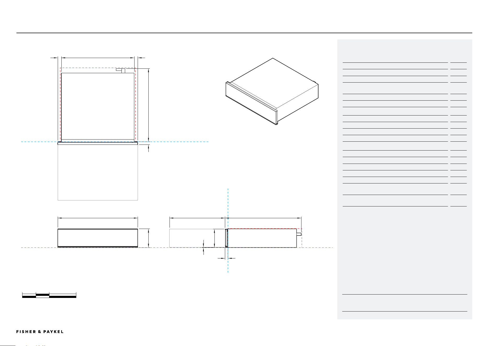
SPECIFICATION GUIDE | VACUUM SEAL DRAWER, 60CM
Vacuum Seal Drawer
Vacuum Seal Drawer VB60SMB1-SET, paired with Steam Oven OS60NMTDB1
Vacuum Seal Drawer VB60SMG1-SET, paired with Steam Oven OS60NMTDG1
VB60SMB1-SET, VB60SMG1-SET
SERIES & STYLE
Series 9
Minimal
FEATURES
1
Seamless pairing with our Minimal style ovens and other
companion products
2 Push-to-open drawer
3 Three levels of vacuum and heat sealing
4 Easy-to-clean base
5 Easy-to-use capacitive touch controls
6 Vacuum sealing for easy food portioning, marinating,
storage and extended shelf life, or re-sealing
7 Effortless preparation for sous vide cooking
8 Maintenance and moisture indicator
ACCESSORIES
1
External vacuuming accessory kit
2 Large BPA free vacuum seal bags (50 bags, part 793034)
3 Small BPA-free vacuum seal bags (50 bags, part 793033)
<< CONTENTS
The models shown in this Planning Guide may not be available in all markets and are subject to change at any time. Product specifications may vary from those shown. This Planning Guide should not be used as installation guidance for any
product. Further information is required to safely and correctly install the products featured here. Specific installation guidance will be available on our website fisherpaykel.com
© FISHER & PAYKEL LIMITED 2024 PAGE 1690003353D PLANNING GUIDE COOKING - VERSION D - APRIL 2024
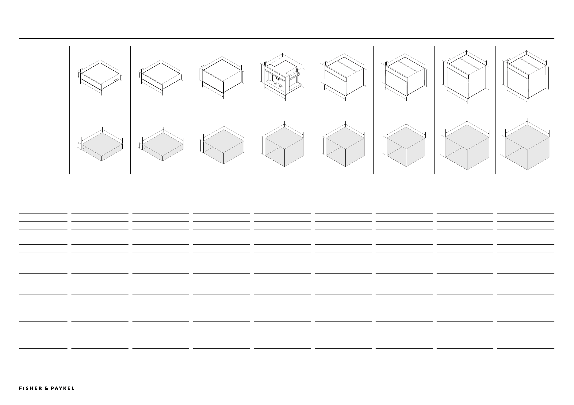
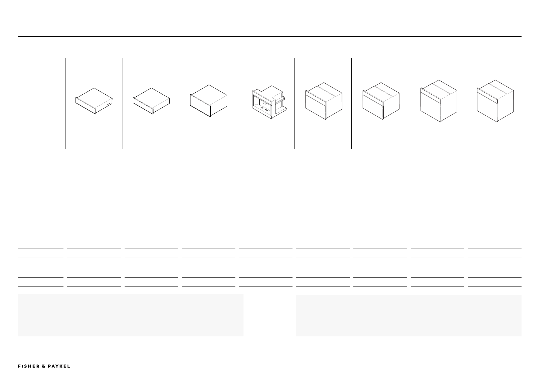
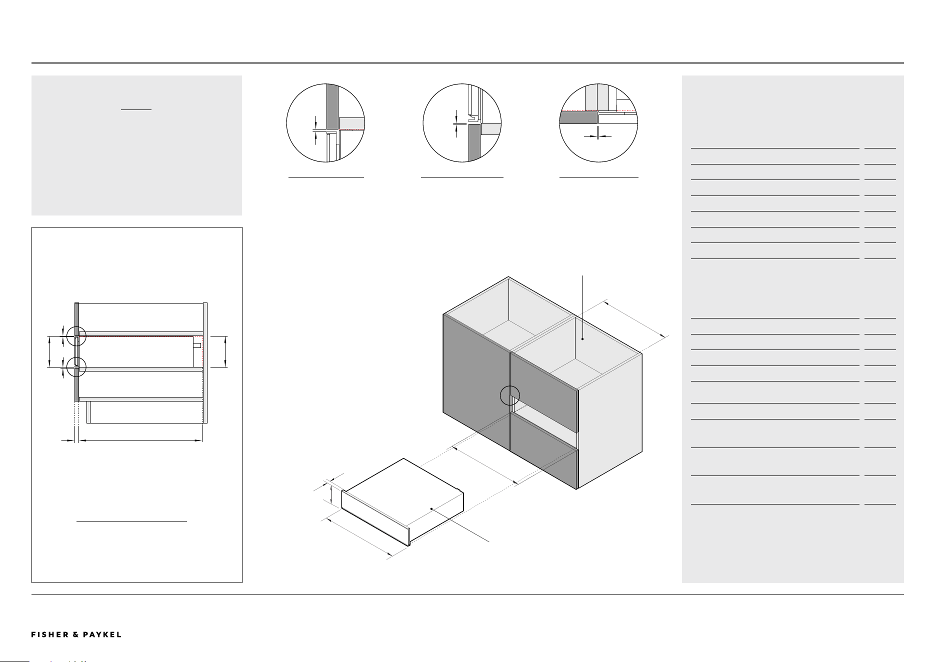
SPECIFICATION GUIDE | DIMENSIONS
PRODUCT
DIMENSIONS
CAVITY
DIMENSIONS
A
B
e
f
VACUUM SEAL DRAWER
VB60SMB1-SET
VB60SMG1-SET
WARMING DRAWER
WB60SMB1-SET
WB60SMG1-SET
WARMING DRAWER TALL
WB60SMTB1-SET
BUILT-IN COFFEE MAKER
EB60MSB1
EB60MSG1
COMBINATION MICROWAVE
OVEN
OM60NMTNB1
OM60NMTNG1
COMBINATION STEAM
OVEN
OS60NMTNB1
OS60NMTNG1
COMBINATION STEAM
OVEN
OS60SMTNB1
OS60SMTNG1
OVEN
OB60SMPTNB1
OB60SMPTNG1
PRODUCT DIMENSIONS
A Overall height 140mm 140mm 290mm 458mm 458mm 458mm 598mm 598mm
B Overall width 596mm 596mm 596mm 596mm 596mm 596mm 596mm 596mm
C Chassis height 140mm 140mm 290mm 445mm 435mm 435mm 575mm 575mm
D Chassis width 556mm** 543mm 543mm 560mm 556mm 556mm 556mm 556mm
E Chassis depth 545mm 547mm 547mm 460mm 545mm 545mm 545mm 545mm
F Front panel thickness 20mm 20mm 20mm 20mm 20mm 20mm 20mm 20mm
Depth of oven door
fully open
- - - - 320mm* 320mm* 460mm* 460mm*
*Measured from front of control panel
**Includes side brackets
CAVITY DIMENSIONS
G Minimum inside height
of cavity
142mm** 142mm** 292mm** 450mm 440mm 440mm 580mm 580mm
H Minimum inside width
of cavity
560mm 560mm 560mm 560mm 560mm 560mm 560mm 560mm
I Minimum inside depth
of cavity
550mm 550mm 550mm 545mm* 550mm* 550mm 550mm 550mm
Recommened cabinet
width
600mm 600mm 600mm 600mm 600mm 600mm 600mm 600mm
*Requires ventilation at the rear of the cavity
**Standalone installation measurement can be installed with appliance on top. Drawers can fully support 60cm Fisher & Paykel wall oven, without adding shelf in between
d
c
g
hI
A
B
e
f
d
c
g
hI
A
B
e
f
d
c
g
h
I
A
B
e
f
d
c
g
h
I
A
B
e
f
d
c
g
h
I
A
B
e
f
d
c
g
h
I
A
B
e
f
d
c
g
h
I
A
B
e
f
d
c
g
h
I
Dimensions - ALL MODELS
ALL MODELS
<< CONTENTS
The models shown in this Planning Guide may not be available in all markets and are subject to change at any time. Product specifications may vary from those shown. This Planning Guide should not be used as installation guidance for any
product. Further information is required to safely and correctly install the products featured here. Specific installation guidance will be available on our website fisherpaykel.com
© FISHER & PAYKEL LIMITED 2024 PAGE 1790003353D PLANNING GUIDE COOKING - VERSION D - APRIL 2024
For more infomation on cord length, water supply and electrical requirements, refer to the
'Services' section of this Planning Guide.
SERVICES
VACUUM SEAL DRAWER
VB60SMB1-SET
VB60SMG1-SET
WARMING DRAWER
WB60SMB1-SET
WB60SMG1-SET
WARMING DRAWER TALL
WB60SMTB1-SET
BUILT-IN COFFEE MAKER
EB60MSB1
EB60MSG1
COMBINATION MICROWAVE
OVEN
OM60NMTNB1
OM60NMTNG1
COMBINATION STEAM
OVEN
OS60NMTNB1
OS60NMTNG1
COMBINATION STEAM
OVEN
OS60SMTNB1
OS60SMTNG1
OVEN
OB60SMPTNB1
OB60SMPTNG1
POWER REQUIREMENTS
Supply 220–240 V, 50 Hz 220–240 V, 50 Hz 220–240 V, 50 Hz 220–240 V, 50 Hz 220–240 V, 50 Hz 220–240 V, 50 Hz 220–240 V, 50 Hz 220–240 V, 50 Hz
Service 10 A 10 A 10 A 10 A 20 A 20 A 20 A 20 A
Connection Flex cord 1800mm Flex cord 1800mm Flex cord 1800mm Flex cord 1700mm Hard wired Hard wired Hard wired Hard wired
WEIGHT
Packaged 42kg 22kg 25kg 39kg 46kg 52kg 65kg 44kg
Unpackaged 35kg 18kg 20kg 29kg 41kg 39kg 46kg 38kg
CAPACITY
Total oven - - - - 49L 55L 85L 85L
Total water tank - - - 2.4L - 1.4L 1.4L -
SPECIFICATION GUIDE | POWER, WEIGHT AND CAPACITY
All Coffee Makers and Steam Ovens have internal water tanks which need to be filled manually.
No external water supply is required.
WATER
Power, Weight and Capacity - ALL MODELS
ALL MODELS
<< CONTENTS

© FISHER & PAYKEL LIMITED 2024 PAGE 1890003353D PLANNING GUIDE COOKING - VERSION D - APRIL 2024
DATA SHEETS
Data Sheets
IMPORTANT NOTE: Throughout this guide, dimensions may vary by ±2mm
(1/16''). Please read the Installation Guide for detailed information on
installing the product. For full installation instructions visit fisherpaykel.com
INDICATES CABINETRY / PRODUCT DATUM -------------------------
INDICATES CABINETRY CLEARANCES --------------------------------
© FISHER & PAYKEL LIMITED 2024 PAGE 1990003353D PLANNING GUIDE COOKING - VERSION D - APRIL 2024
DATUM : BOTTOM OF CHASSIS
DATUM : FRONT OF CHASSIS
POWER OUTLET LOCATION
DATUM : FRONT OF CHASSIS
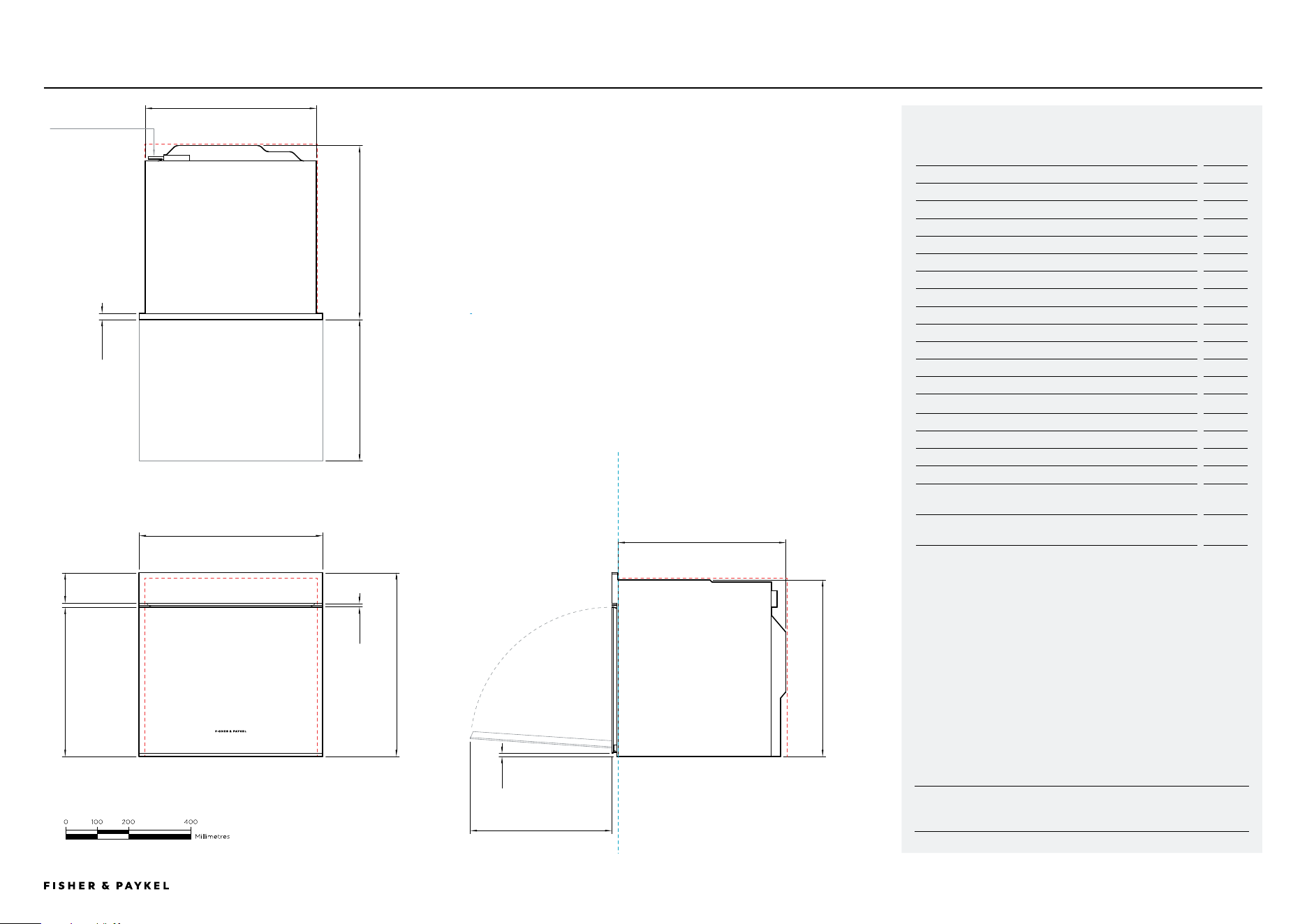
FRONT VIEW
PLAN VIEW
PROFILE VIEW
OB60SMPTNB1, OB60SMPTNG1
Model no:
Oven, 60cm - OB60SMPTNB1, OB60SMPTNG1
Product Dimensions
mm
A Overall height of product
598
B Overall width of product
596
C Depth of control panel
20
D Depth of chassis and control panel
565
E Depth of chassis
545
F Height of chassis
575
G Width of chassis
556
H Height from bottom datum to top of oven door
487
I Height from bottom datum to bottom of door
12
J Height of control panel
100
K Gap between door and control panel
11
L Depth of door when open (measured from front of door)
460
Minimum Clearances - Flush Installation
mm
Minimum inside height of cavity
580
Minimum inside width of cavity
560
Minimum inside depth of cavity
550
Minimum clearances above oven control panel to upper cabinetry
front panel or appliance
2
Minimum clearances between bottom of oven chassis to lower
cabinetry front panel or appliance
2
Ensure a 5mm minimum clearance is maintained between the top of the oven chassis and
the cabinetry. Ensure the oven is not bearing any weight from cabinetry or products installed
above.
IMPORTANT NOTE: For full installation and clearance details please refer to our installation
manual.
DATA SHEET | OVEN, 60CM
Oven
A
B
C
D
E
F
G
H
I
J
K
L
596
598
565
L
<< CONTENTS
IMPORTANT NOTE: Throughout this guide, dimensions may vary by ±2mm
(1/16''). Please read the Installation Guide for detailed information on
installing the product. For full installation instructions visit fisherpaykel.com
INDICATES CABINETRY / PRODUCT DATUM -------------------------
INDICATES CABINETRY CLEARANCES --------------------------------
© FISHER & PAYKEL LIMITED 2024 PAGE 2090003353D PLANNING GUIDE COOKING - VERSION D - APRIL 2024
DATUM : BOTTOM OF CHAS
SIS
DATUM : FRONT OF CHASSIS
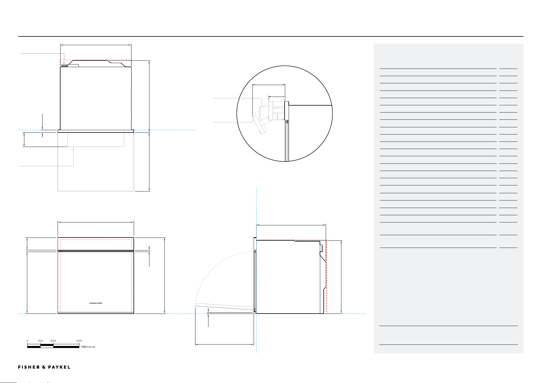
FRONT VIEW
PLAN VIEW
PROFILE VIEW
POWER OUTLET LOCATION
DATUM : FRONT OF CHASSIS
WATER TANK
CONTROL PANEL
WATER TANK FULLY OPEN
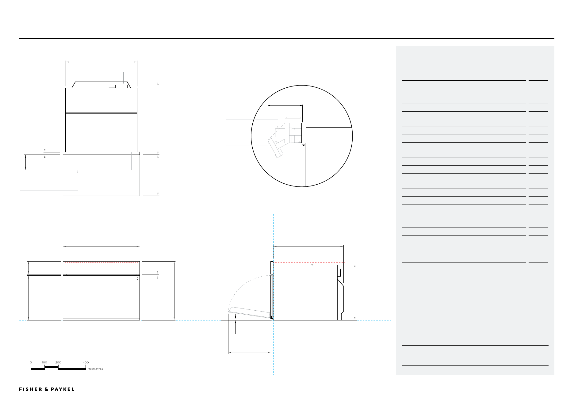
Model no:
Combination Steam Oven, 60cm - OS60SMTNB1, OS60SMTNG1
Product Dimensions
mm
A Overall height of product
598
B Overall width of product
596
C Depth of control panel
20
D Depth of chassis and control panel
565
E Depth of chassis
545
F Height of chassis
575
G Width of chassis
556
H Height from bottom datum to top of oven door
487
I Height from bottom datum to bottom of door
12
J Height of control panel
100
K Gap between door and control panel
11
L Depth of door when open (measured from front of door)
460
M Control panel fully open (measured from front of door)
170
N Control panel half open (measured from front of door)
84
O Water tank carriage fully open (measured from front of door)
133
Minimum Clearances - Flush Installation
mm
Minimum inside height of cavity
580
Minimum inside width of cavity
560
Minimum inside depth of cavity
550
Minimum clearances above oven control panel to upper cabinetry
front panel or appliance
2
Minimum clearances between bottom of oven chassis to lower
cabinetry front panel or appliance
2
Ensure a 5mm minimum clearance is maintained between the top of the oven chassis and
the cabinetry. Ensure the oven is not bearing any weight from cabinetry or products installed
above.
IMPORTANT NOTE: For full installation and clearance details please refer to our installation
manual.
A
C
D
F
G
H
I
J
K
L
M
N
O
L
OS60SMTNB1, OS60SMTNG1
DATA SHEET | COMBINATION STEAM OVEN, 60CM
Combination Steam Oven
B
596
E
598
565
<< CONTENTS
IMPORTANT NOTE: Throughout this guide, dimensions may vary by ±2mm
(1/16''). Please read the Installation Guide for detailed information on
installing the product. For full installation instructions visit fisherpaykel.com
INDICATES CABINETRY / PRODUCT DATUM -------------------------
INDICATES CABINETRY CLEARANCES --------------------------------
© FISHER & PAYKEL LIMITED 2024 PAGE 2190003353D PLANNING GUIDE COOKING - VERSION D - APRIL 2024
DATA SHEET | COMBINATION STEAM OVEN, 60CM
A
B
C
D
E
F
H
I
J
K
L
M
N
O
L
Combination Steam Oven
G
PLAN VIEW
FRONT VIEW
PROFILE
VIEW
POWER OUTLET LOCATION
DATUM : BOTTOM OF CHASSIS
DATUM : FRONT OF CHASSIS
DATUM : FRONT OF CHASSIS
WATER TANK
CONTROL PANEL
WATER TANK FULLY OPEN
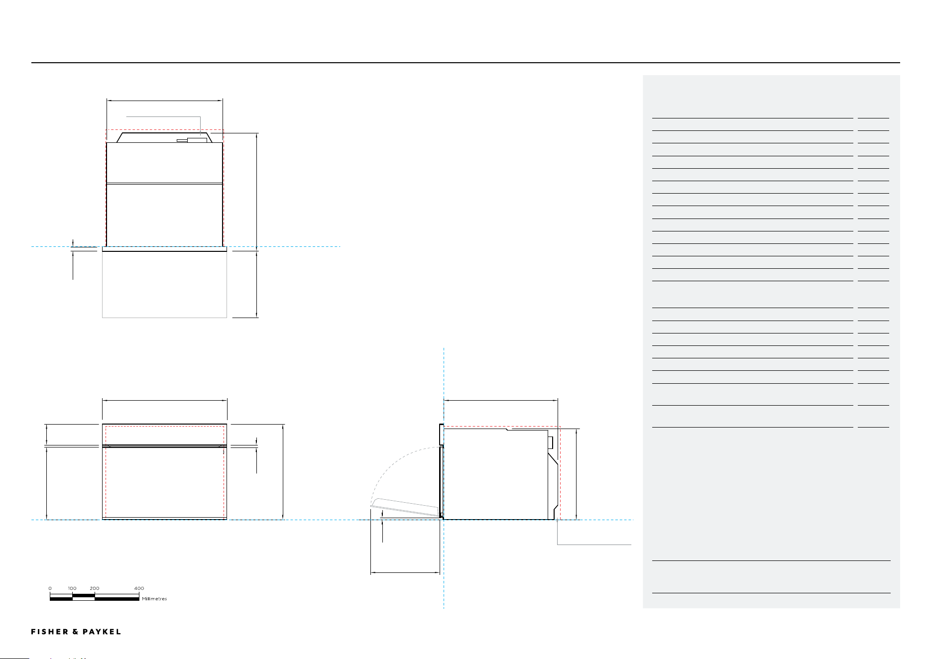
OS60NMTNB1, OS60NMTNG1
Model no:
Combination Steam Oven, 60cm - OS60NMTNB1, OS60NMTNG1
Product Dimensions
mm
A Overall height of product
458
B Overall width of product
596
C Depth of control panel
20
D Depth of chassis and control panel
565
E Depth of chassis
545
F Height of chassis
435
G Width of chassis
556
H Height from bottom datum to top of oven door
347
I Height from bottom datum to bottom of door
12
J Height of control panel
100
K Gap between door and control panel
11
L Depth of door when open (measured from front of door)
320
M Control panel fully open (measured from front of door)
170
N Control panel half open (measured from front of door)
84
O Water tank carriage fully open (measured from front of door)
133
Minimum Clearances - Flush Installation
mm
Minimum inside height of cavity
440
Minimum inside width of cavity
560
Minimum inside depth of cavity
550
Minimum clearances above oven control panel to upper cabinetry
front panel or appliance
2
Minimum clearances between bottom of oven chassis to lower
cabinetry front panel or appliance
2
Ensure a 5mm minimum clearance is maintained between the top of the oven chassis and
the cabinetry. Ensure the oven is not bearing any weight from cabinetry or products installed
above.
IMPORTANT NOTE: For full installation and clearance details please refer to our installation
manual.
596
458
565
<< CONTENTS
IMPORTANT NOTE: Throughout this guide, dimensions may vary by ±2mm
(1/16''). Please read the Installation Guide for detailed information on
installing the product. For full installation instructions visit fisherpaykel.com
INDICATES CABINETRY / PRODUCT DATUM -------------------------
INDICATES CABINETRY CLEARANCES --------------------------------
© FISHER & PAYKEL LIMITED 2024 PAGE 2290003353D PLANNING GUIDE COOKING - VERSION D - APRIL 2024
Combination Microwave Oven
DATA SHEET | COMBINATION MICROWAVE OVEN, 60CM OM60NMTNB1, OM60NMTNG1
Model no:
Combination Microwave Oven, 60cm - OM60NMTNB1, OM60NMTNG1
Product Dimensions
mm
A Overall height of product
458
B Overall width of product
596
C Depth of control panel
20
D Depth of chassis and control panel
565
E Depth of chassis
545
F Height of chassis
435
G Width of chassis
556
H Height from bottom datum to top of oven door
347
I Height from bottom datum to bottom of door
12
J Height of control panel
100
K Gap between door and control panel
11
L Depth of door when open (measured from front of door)
320
Minimum Clearances - Flush Installation
mm
Minimum inside height of cavity
440
Minimum inside width of cavity
560
Minimum inside depth of cavity
550
Rear ventilation air vent depth*
50
Rear ventilation air vent width*
560
Minimum clearances above oven control panel to upper cabinetry
front panel or appliance
2
Minimum clearances between bottom of oven chassis to lower
cabinetry front panel or appliance
2
*A rear ventilation air vent totalling 280cm2 is required. The air vent must be located at the rear
of the cabinet, it can be positioned at the base, sides, back or top of the cavity.
Ensure a 5mm minimum clearance is maintained between the top of the oven chassis and the
cabinetry. Ensure the oven is not bearing any weight from cabinetry or products installed above.
IMPORTANT NOTE: For full installation and clearance details please refer to our installation
manual.
A
B
C
D
G
H
J
K
L
PLAN VIEW
FRONT VIEW
PROFILE
VIEW
VENTILATION
POWER OUTLET LOCATION
DATUM : BOTTOM OF CHAS
SIS
DATUM : FRONT OF CHASSIS
DATUM : FRONT OF CHASSIS
596
458
E
F
I
L
565
<< CONTENTS
IMPORTANT NOTE: Throughout this guide, dimensions may vary by ±2mm
(1/16''). Please read the Installation Guide for detailed information on
installing the product. For full installation instructions visit fisherpaykel.com
INDICATES CABINETRY / PRODUCT DATUM -------------------------
INDICATES CABINETRY CLEARANCES --------------------------------
© FISHER & PAYKEL LIMITED 2024 PAGE 2390003353D PLANNING GUIDE COOKING - VERSION D - APRIL 2024
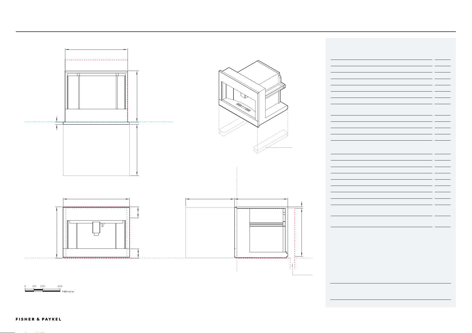
Model no:
Built-in Coffee Maker, 60cm - EB60MSB1, EB60MSG1
Product Dimensions
mm
A Overall height of product
458
B Overall width of product
596
C Overall depth of product (excludes front metal trim)
480
D Height of chassis
445
E Width of chassis
560
F Depth of chassis
460
G Depth of coffee maker front frame and control panel (excludes
front metal trim)
20
H Height of control panel
100
I Height of horizontal lower section from bottom datum
83
J Stepdown from control panel to chassis
13
K Extent coffee maker pulls out
435
Minimum Clearances - Flush Installation
mm
Minimum inside height of cavity
450
Minimum inside width of cavity
560
Minimum inside depth of cavity from front datum
545
Overall height of cabinetry
460
Overall width of cabinetry
600
Rear ventilation air vent depth*
50
Rear ventilation air vent width*
560
Minimum clearances above built-in coffee maker control panel to
upper cabinetry front panel or appliance
2
Minimum clearances between bottom of coffee maker rails to
lower cabinetry front panel or appliance
2
*A rear ventilation air vent totalling 280cm2 is required. The air vent must be
located at the rear of cabinet. It can be positioned at the base, sides, back or
top of the cavity.
IMPORTANT NOTE: For full installation and clearance details please refer to our installation
manual.
DATUM : FRONT OF CHASSIS
PLAN VIEW
DATUM : BOTTOM OF CHASSIS
DATUM : FRONT OF CHASSIS
SPACERS OPTIONAL,
SUPPLIED WITH
COFFEEMAKER
NOT TO SCALE
VENTILATION
FRONT VIEW PROFILE VIEW
DATA SHEET | BUILT-IN COFFEE MAKER, 60CM EB60MSB1, EB60MSG1
I
B
G
F
C
D
E
A
K
H
K
J
Built-in Coee Maker
596
458
480
<< CONTENTS
IMPORTANT NOTE: Throughout this guide, dimensions may vary by ±2mm
(1/16''). Please read the Installation Guide for detailed information on
installing the product. For full installation instructions visit fisherpaykel.com
INDICATES CABINETRY / PRODUCT DATUM -------------------------
INDICATES CABINETRY CLEARANCES --------------------------------
© FISHER & PAYKEL LIMITED 2024 PAGE 2490003353D PLANNING GUIDE COOKING - VERSION D - APRIL 2024
WB60SMTB1-SETDATA SHEET | WARMING DRAWER, 60CM, TALL
Warming Drawer, Tall
NOT TO SCALE
FRONT VIEW
PLAN VIEW
PROFILE VIEW
DATUM : FRONT OF CHASSIS
DATUM : BOTTOM OF PRODUCT
DATUM : FRONT OF CHASSIS
0 100 200 400
millimetres
IB
G
C
F
E
A
J
D
F
HH
290
564596
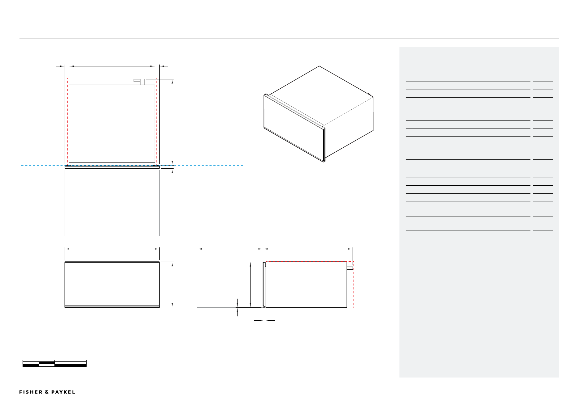
Model no:
Warming Drawer, 60cm, Tall - WB60SMTB1-SET
Product Dimensions
mm
A Overall height of product
290
B Overall width of product
596
C Overall depth (incl. front panel & power plug)
564
D Height of drawer front panel
286
E Width of chassis
543
F Depth of drawer front panel and flange
20
G Depth of chassis (includes power plug, excludes flange)
547
H Distance from side of chassis to side of drawer front
36
I Depth of open drawer (mesured from front of drawer panel)
414
J Height from bottom of chassis to bottom of front panel
2
Dimension Clearances - Flush Installation
mm
Minimum inside height of cavity
292
Minimum inside width of cavity
560
Minimum inside depth of cavity
550
Overall width of cabinetry
600
Minimum clearances above drawer front panel to upper cabinetry
front panel or appliance*
4
Minimum clearances between bottom of drawer chassis to lower
cabinetry front panel or appliance
2
*Achieve a smaller gap between drawer front panel to upper cabinetry front panel by dropping
cabinetry front panel down
IMPORTANT NOTE: For full installation and clearance details please refer to our installation
manual.
<< CONTENTS
IMPORTANT NOTE: Throughout this guide, dimensions may vary by ±2mm
(1/16''). Please read the Installation Guide for detailed information on
installing the product. For full installation instructions visit fisherpaykel.com
INDICATES CABINETRY / PRODUCT DATUM -------------------------
INDICATES CABINETRY CLEARANCES --------------------------------
© FISHER & PAYKEL LIMITED 2024 PAGE 2590003353D PLANNING GUIDE COOKING - VERSION D - APRIL 2024
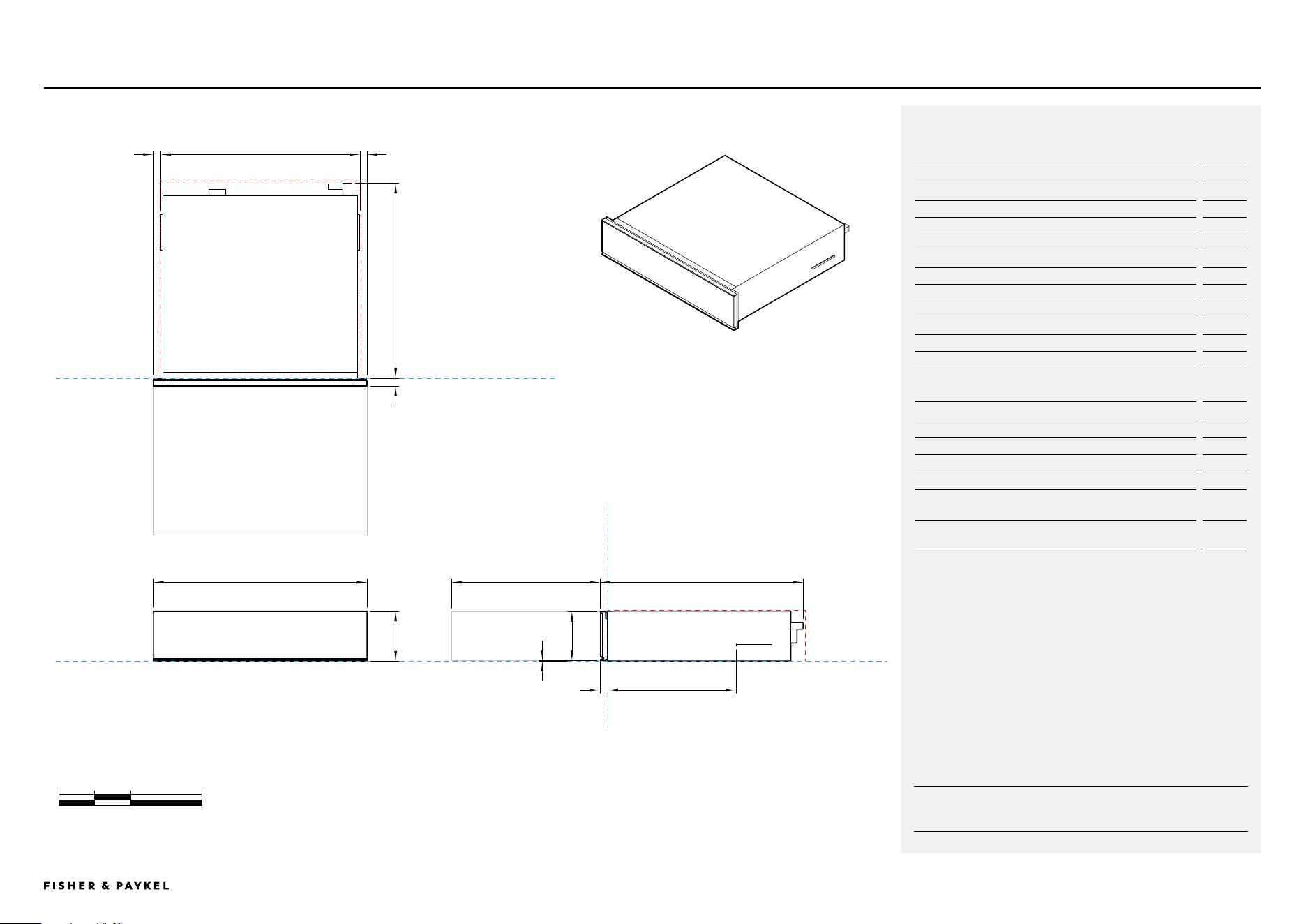
WB60SMB1-SET, WB60SMG1-SETDATA SHEET | WARMING DRAWER, 60CM
Warming Drawer
NOT TO SCALE
0 100 200 400
millimetres
FRONT VIEW
PLAN VIEW
PROFILE VIEW
DATUM : FRONT OF CHASSIS
DATUM : BOTTOM OF PRODUCT
DATUM : FRONT OF CHASSIS
IB
G
C
F
E
A
J
D
F
HH
140
567596
Model no:
Warming Drawer, 60cm - WB60SMB1-SET, WB60SMG1-SET
Product Dimensions
mm
A Overall height of product
140
B Overall width of product
596
C Overall depth (incl. front panel & power plug, excludes
stainless cap)
567
D Height of drawer front panel
136
E Width of chassis
543
F Depth of drawer front panel and flange
(excludes stainless cap)
20
G Depth of chassis (includes power plug, excludes flange)
547
H Distance from side of chassis to side of drawer front
36
I Depth of open drawer (mesured from front of drawer panel)
414
J Height from bottom of chassis to bottom of front panel
2
Dimension Clearances - Flush Installation
mm
Minimum inside height of cavity
142
Minimum inside width of cavity
560
Minimum inside depth of cavity
550
Overall width of cabinetry
600
Minimum clearances above drawer front panel to upper cabinetry
front panel or appliance*
4
Minimum clearances between bottom of drawer chassis to lower
cabinetry front panel or appliance
2
*Achieve a smaller gap between drawer front panel to upper cabinetry front panel by dropping
cabinetry front panel down
IMPORTANT NOTE: For full installation and clearance details please refer to our installation
manual.
<< CONTENTS
IMPORTANT NOTE: Throughout this guide, dimensions may vary by ±2mm
(1/16''). Please read the Installation Guide for detailed information on
installing the product. For full installation instructions visit fisherpaykel.com
INDICATES CABINETRY / PRODUCT DATUM -------------------------
INDICATES CABINETRY CLEARANCES --------------------------------
© FISHER & PAYKEL LIMITED 2024 PAGE 2690003353D PLANNING GUIDE COOKING - VERSION D - APRIL 2024
VB60SMB1-SET, VB60SMG1-SET DATA SHEET | VACUUM SEAL DRAWER, 60CM
Vacuum Seal Drawer
NOT TO SCALE
PLAN VIEW
FRONT VIEW PROFILE VIEW
DATUM : FRONT OF CHASSIS
DATUM : BOTTOM OF PRODUCT
DATUM : FRONT OF CHASSIS
0 100 200 400
millimetres
I
B
G
C
F
E
A
J
D
F
HH
K
140
565596
Model no:
Vacuum Seal Drawer - VB60SMB1-SET, VB60SMG1-SET
Product Dimensions
mm
A Overall height of product
140
B Overall width of product
596
C Overall depth (incl. front panel & power plug)
565
D Height of drawer front panel
136
E Width of chassis (includes side brackets)
556
F Depth of drawer front panel and flange
20
G Depth of chassis (includes power plug, excludes flange)
545
H Distance from side bracket to side of drawer front
20
I Distance between flange and side bracket
358
J Depth of open drawer (measured from front of drawer panel)
414
K Height from bottom of chassis to bottom of front panel
2
IMPORTANT NOTE: For full installation and clearance details please refer to our installation
manual.
Dimension Clearances - Flush Installation
mm
Minimum inside height of cavity
142
Minimum inside width of cavity
560
Minimum inside depth of cavity
550
Overall width of cabinetry
600
Minimum clearances above drawer front panel to upper cabinetry
front panel or appliance*
4
Minimum clearances between bottom of drawer chassis to lower
cabinetry front panel or appliance
2
*Achieve a smaller gap between drawer front panel to upper cabinetry front panel by dropping
cabinetry front panel down
<< CONTENTS

© FISHER & PAYKEL LIMITED 2024 PAGE 2790003353D PLANNING GUIDE COOKING - VERSION D - APRIL 2024
PLANNING CONSIDERATIONS
Planning Considerations
The models shown in this Planning Guide may not be available in all markets and are subject to change at any time. Product specifications may vary from those shown. This Planning Guide should not be used as installation guidance for any
product. Further information is required to safely and correctly install the products featured here. Specific installation guidance will be available on our website fisherpaykel.com
© FISHER & PAYKEL LIMITED 2024 PAGE 2890003353D PLANNING GUIDE COOKING - VERSION D - APRIL 2024
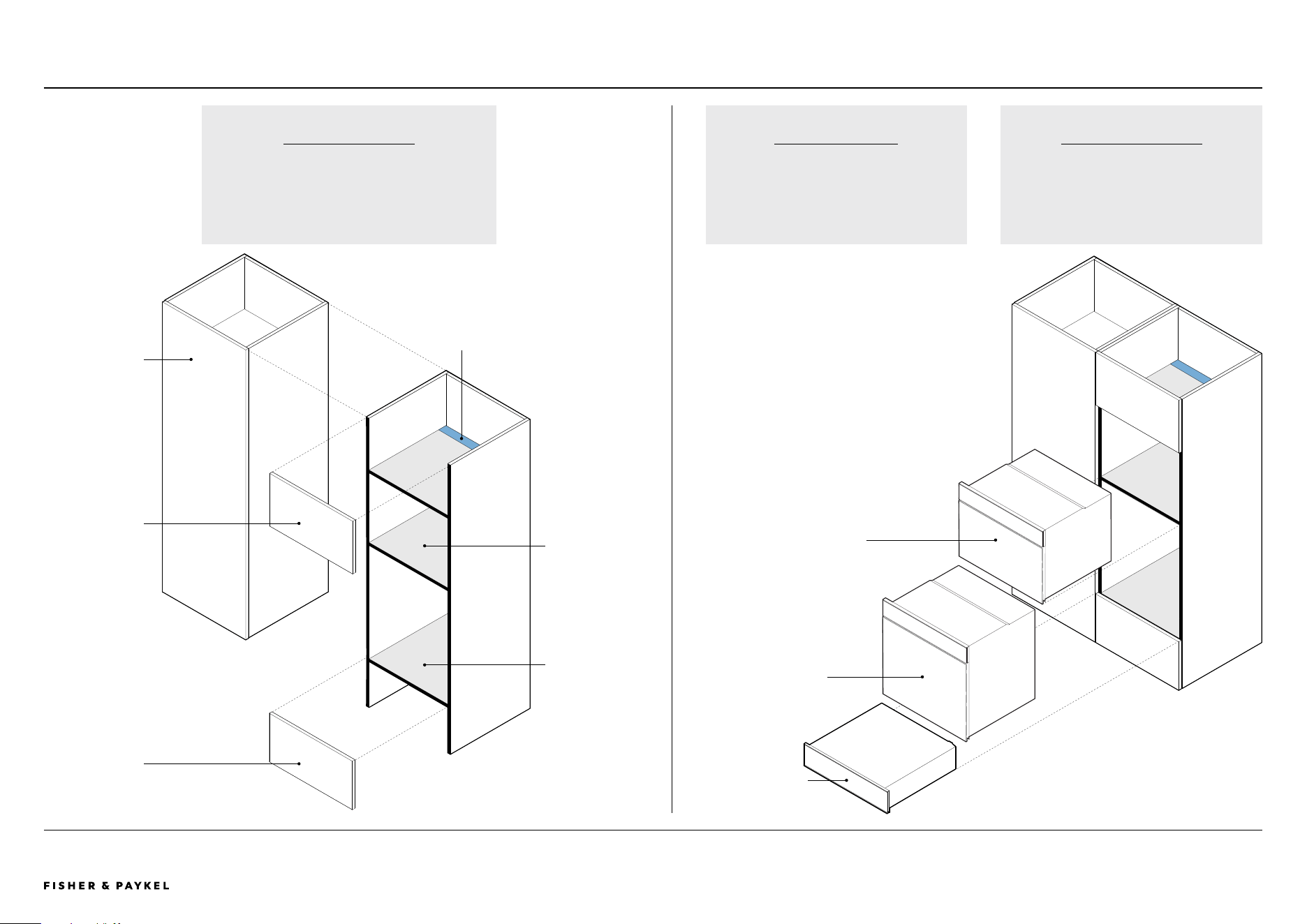
PLANNING CONSIDERATIONS | CABINETRY PREPARATION
Cabinetry Preparation - ALL MODELS
BLACK CLASHING
Black clashing recommended on front facing
edges where products are located and on side
cabinets where cabinet is rebated.
ALL MODELS
DIVIDING SHELF
If the cabinetry front panels are thinner
than 20mm (less than the thickness of the
appliance front) a rebate is required for the
appliance to achieve a flush finish.
BLACK CLASHING
Black clashing recommended on front facing
edges where products are located and on side
cabinets if cabinet is rebated.
Combination Steam Oven or
Combination Microwave Oven or
Built-in Coffee Maker
Oven or Combination
Steam Oven
Warming Drawer, Tall
or Warming Drawer or
Vacuum Seal Drawer
Dividing shelf
Cabinetry front
panel below
Cabinetry front
panel above
Adjacent cabinet
Supporting shelf
Ventilation gap
LEVEL CABINETRY
Check the shelves are level and the side
panels are straight.
<< CONTENTS
The models shown in this Planning Guide may not be available in all markets and are subject to change at any time. Product specifications may vary from those shown. This Planning Guide should not be used as installation guidance for any
product. Further information is required to safely and correctly install the products featured here. Specific installation guidance will be available on our website fisherpaykel.com
© FISHER & PAYKEL LIMITED 2024 PAGE 2990003353D PLANNING GUIDE COOKING - VERSION D - APRIL 2024
PLANNING CONSIDERATIONS | CONFIGURATIONS, 60CM
VACUUM SEAL DRAWER
VB60SMB1-SET
VB60SMG1-SET
WARMING DRAWER
WB60SMB1-SET
WB60SMG1-SET
WARMING DRAWER TALL
WB60SMTB1-SET
BUILT-IN COFFEE MAKER
EB60MSB1
EB60MSG1
COMBINATION MICROWAVE
OVEN
OM60NMTNB1
OM60NMTNG1
COMBINATION STEAM
OVEN
OS60NMTNB1
OS60NMTNG1
COMBINATION STEAM
OVEN
OS60SMTNB1
OS60SMTNG1
OVEN
OB60SMPTNB1
OB60SMPTNG1
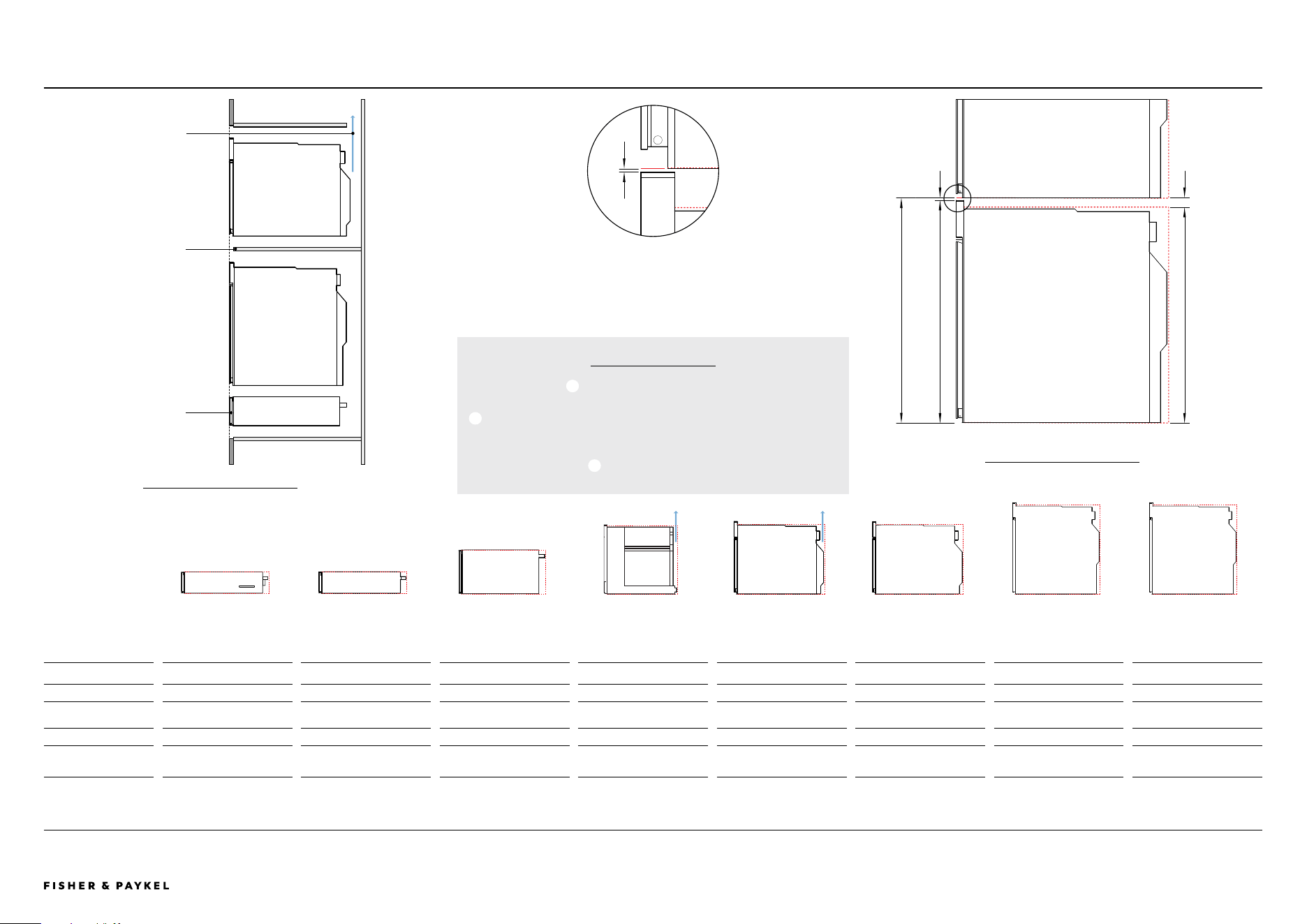
DIMENSIONS
A Overall product height 140mm 140mm 290mm 458mm*** 458mm 458mm 598mm 598mm
B Minimum clearance
above
- - - 2mm 2mm 2mm 2mm 2mm
C Stack height 140mm** 140mm** 290mm** 460mm* 460mm* 460mm* 600mm* 600mm*
D Minimum inside height
of cavity
140mm 140mm 290mm 450mm 440mm 440mm 580mm 580mm
*Stack Height is overall product height with minimum clearances above appliance control panel or front panel to upper appliance
**Warming Drawers and Vacuum Seal Drawers can fully support a 60cm Fisher & Paykel oven, without adding a shelf in between.
***Includes coffee maker rail height
Configurations - ALL MODELS
MINIMUM
DIMENSION
CLEARANCES
Warming Drawers and
Vacuum Seal Drawers can
fully support a 60cm Fisher
& Paykel oven, without
adding a shelf in between.
Dividing shelves are
required to support stacked
appliances and to achieve
correct clearance.
Ventilation air vent is
required at rear for some
products.
PRODUCT
PROFILE VIEW
Dividing shelf
location, shelf
must be above
min inside height
of cavity.
STACK EXPLODED
PROFILE VIEW
ALL MODELS
Dividing shelves must be
constructed from material
that will support the weight
of the appliances.
Ensure the oven is not
bearing any weight from
cabinetry or products
installed above.
C
D
BACKFRONT
Stack Height
Minimum inside height of cavity
A
B
Minimum clearances above appliance control panel to upper
appliance
B
Overall product height
+
Minimum clearances above appliance control panel or
front panel to upper appliance
=
Stacked Height
STACK HEIGHT
A
B
C
2mm
<< CONTENTS
The models shown in this Planning Guide may not be available in all markets and are subject to change at any time. Product specifications may vary from those shown. This Planning Guide should not be used as installation guidance for any
product. Further information is required to safely and correctly install the products featured here. Specific installation guidance will be available on our website fisherpaykel.com
© FISHER & PAYKEL LIMITED 2024 PAGE 3090003353D PLANNING GUIDE COOKING - VERSION D - APRIL 2024
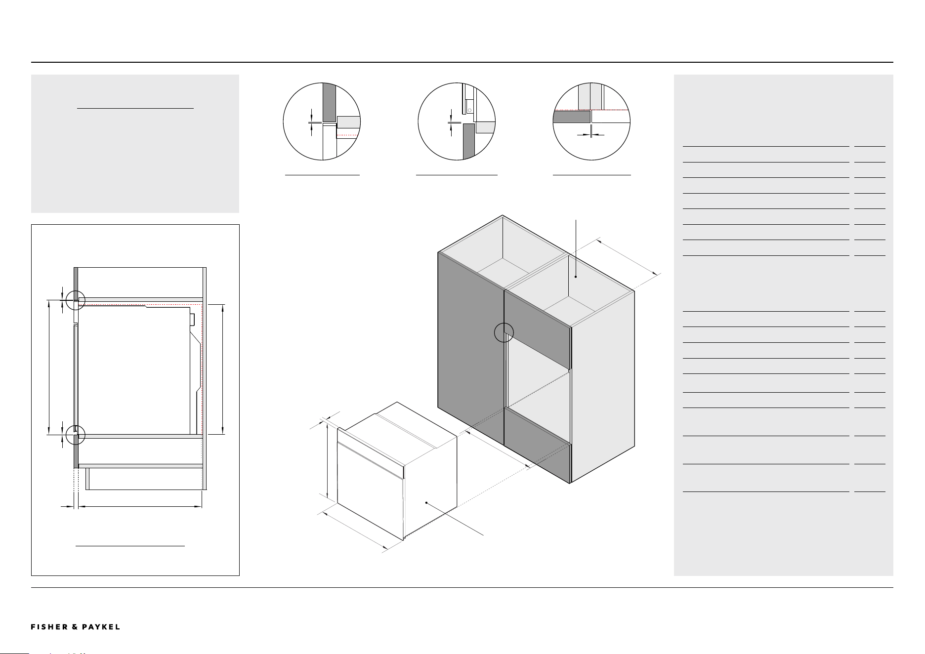
PLANNING CONSIDERATIONS | OVEN, 60CM
Model no:
Oven - OB60SMPTNB1, OB60SMPTNG1
Cabinetry Dimensions - Flush
mm
A Overall cabinet height*
600
B Overall cabinet width
600
C Minimum inside width of cavity
560
D Minimum inside height of cavity
580
E Minimum inside depth of cavity
550
F Thickness of cabinetry front panel** 16-20
*Overall cabinet height is overall product height with minimum clearances above
oven control panel to upper cabinetry front panel
**Cabinetry shown in drawings 19mm panels. If the front panel is thinner than
20mm a rebate for the Oven is required to achieve a flush finish
Product Dimensions mm
G Overall height of product 598
H Overall width of product 596
I Thickness of oven front panel 20
Cabinetry Clearances mm
J Minimum clearances above oven control panel to
upper cabinetry front panel
2
K Minimum clearances between bottom of oven
chassis to lower cabinetry front panel
2
L Minimum clearance between adjacent front panel
or appliance
2
OB60SMPTNB1, OB60SMPTNG1
CLEARANCE ABOVE
PROFILE VIEW
J
1
BACKFRONT
CABINETRY
PROFILE VIEW
EF
J
K
A
D
2
1
Oven
H
I
G
Closed cabinetry
3
2
CLEARANCE BOTTOM
PROFILE VIEW
K
ADJACENT CABINET
PLAN VIEW
L
3
Oven
C
B
COOKTOP CLEARANCE
If installing a cooktop above the oven,
ensure adequate clearance is provided for the
cooktop as per the cooktop manufacturer’s
instructions.
<< CONTENTS

The models shown in this Planning Guide may not be available in all markets and are subject to change at any time. Product specifications may vary from those shown. This Planning Guide should not be used as installation guidance for any
product. Further information is required to safely and correctly install the products featured here. Specific installation guidance will be available on our website fisherpaykel.com
© FISHER & PAYKEL LIMITED 2024 PAGE 3190003353D PLANNING GUIDE COOKING - VERSION D - APRIL 2024
Combination Steam Oven
Model no:
Combination Steam Oven - OS60SMTNB1, OS60SMTNG1
Cabinetry Dimensions - Flush
mm
A Overall cabinet Height*
600
B Overall cabinet width
600
C Minimum inside width of cavity
560
D Minimum inside height of cavity
580
E Minimum inside depth of cavity
550
F Thickness of cabinetry front panel** 16-20
*Overall cabinet height is overall product height with minimum clearances above
oven control panel to upper cabinetry front panel
**Cabinetry shown in drawings 19mm panels. If the front panel is thinner than
20mm a rebate for the Oven is required to achieve a flush finish
Product Dimensions mm
G Overall height of product 598
H Overall width of product 596
I Thickness of oven front panel 20
Cabinetry Clearances mm
J Minimum clearances above oven control panel to
upper cabinetry front panel
2
K Minimum clearances between bottom of oven
chassis to lower cabinetry front panel
2
L Minimum clearance between adjacent front panel
or appliance
2
BACKFRONT
CABINETRY
PROFILE VIEW
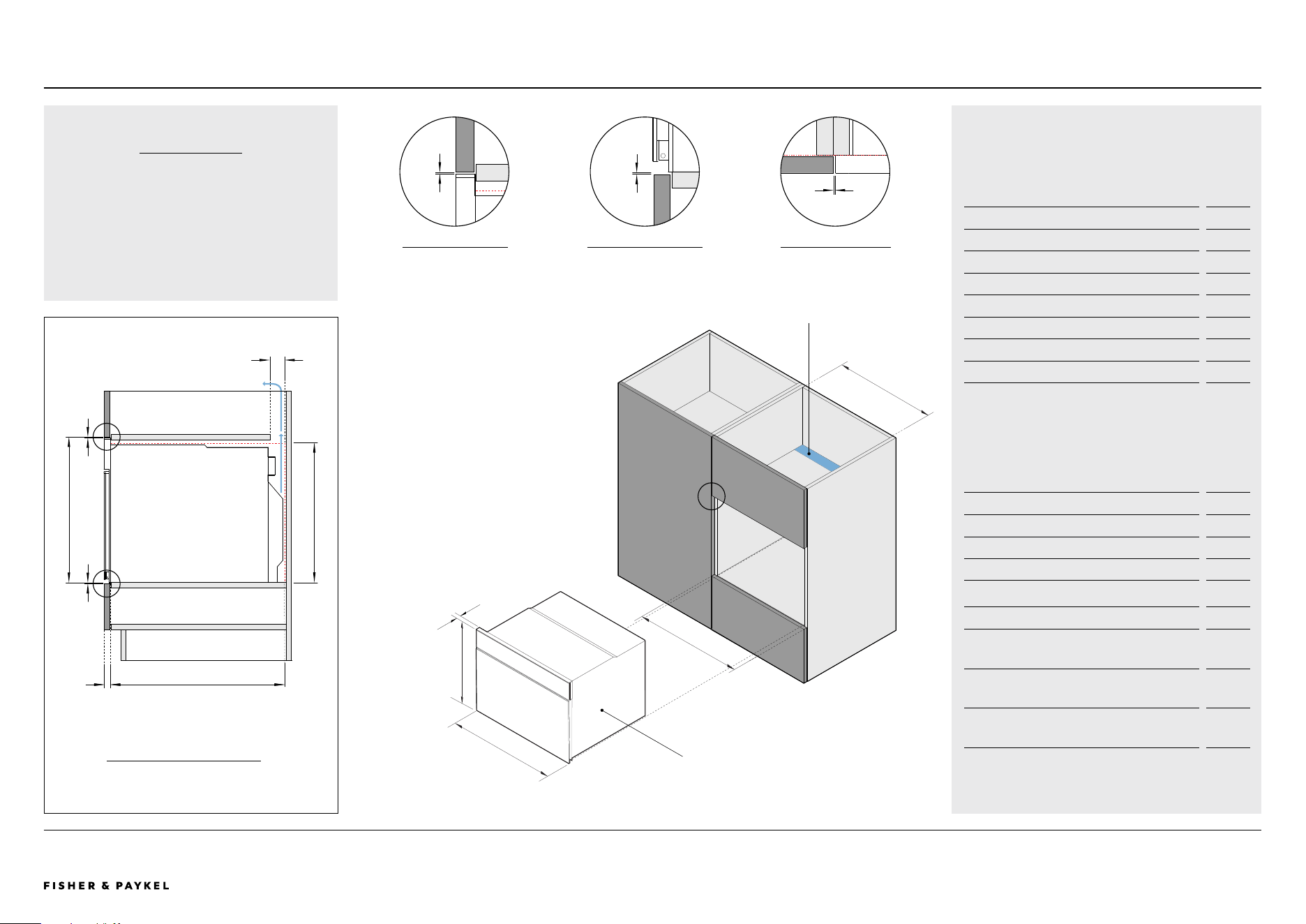
PLANNING CONSIDERATIONS | COMBINATION STEAM OVEN, 60CM OS60SMTNB1, OS60SMTNG1
Combination Steam Oven
2
1
COOKTOP CLEARANCE
If installing a cooktop above the oven,
ensure adequate clearance is provided for the
cooktop as per the cooktop manufacturer’s
instructions.
Closed cabinetry
CLEARANCE ABOVE
PROFILE VIEW
1 2
CLEARANCE BOTTOM
PROFILE VIEW
ADJACENT CABINET
PLAN VIEW
3
3
EF
J
K
A
D
H
I
G
C
B
J
K
L
<< CONTENTS

The models shown in this Planning Guide may not be available in all markets and are subject to change at any time. Product specifications may vary from those shown. This Planning Guide should not be used as installation guidance for any
product. Further information is required to safely and correctly install the products featured here. Specific installation guidance will be available on our website fisherpaykel.com
© FISHER & PAYKEL LIMITED 2024 PAGE 3290003353D PLANNING GUIDE COOKING - VERSION D - APRIL 2024
Model no:
Combination Steam Oven - OS60NMTNB1, OS60NMTNG1
Cabinetry Dimensions - Flush
mm
A Overall cabinet height*
460
B Overall cabinet width
600
C Minimum inside width of cavity***
560
D Minimum inside height of cavity
440
E Minimum inside depth of cavity
550
F Thickness of cabinetry front panel** 16-20
*Overall cabinet height is overall product height with minimum clearances above
oven control panel to upper cabinetry front panel
**Cabinetry shown in drawings 19mm panels. If the front panel is thinner than
20mm a rebate for the Oven is required to achieve a flush finish
Product Dimensions mm
G Overall height of product 458
H Overall width of product 596
I Thickness of oven front panel 20
Cabinetry Clearances mm
J Minimum clearances above oven control panel to
upper cabinetry front panel
2
K Minimum clearances between bottom of oven
chassis to lower cabinetry front panel
2
L Minimum clearance between adjacent front panel
or appliance
2
BACKFRONT
CABINETRY
PROFILE VIEW
A
EF
K
L
D
PLANNING CONSIDERATIONS | COMBINATION STEAM OVEN, 60CM OS60NMTNB1, OS60NMTNG1
Combination Steam Oven
I
J
H
K
L
M
2
1
3
Combination Steam Oven
C
B
COOKTOP CLEARANCE
If installing a cooktop above the oven,
ensure adequate clearance is provided for the
cooktop as per the cooktop manufacturer’s
instructions.
Closed cabinetry
CLEARANCE ABOVE
PROFILE VIEW
1 2
CLEARANCE BOTTOM
PROFILE VIEW
ADJACENT CABINET
PLAN VIEW
3
<< CONTENTS
The models shown in this Planning Guide may not be available in all markets and are subject to change at any time. Product specifications may vary from those shown. This Planning Guide should not be used as installation guidance for any
product. Further information is required to safely and correctly install the products featured here. Specific installation guidance will be available on our website fisherpaykel.com
© FISHER & PAYKEL LIMITED 2024 PAGE 3390003353D PLANNING GUIDE COOKING - VERSION D - APRIL 2024
Cooktop Clearance
If installing a cooktop above the oven,
ensure adequate clearance is provided for the
cooktop as per the cooktop manufacturer’s
instructions.
BACKFRONT
A
EF
K
L
D
G
CABINETRY
PROFILE VIEW
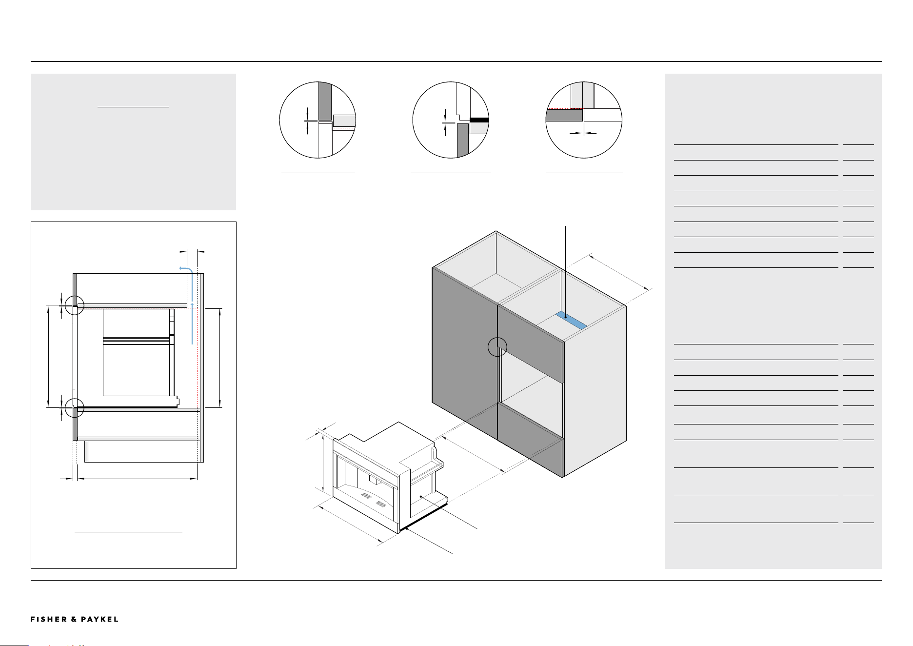
PLANNING CONSIDERATIONS | COMBINATION MICROWAVE OVEN, 60CM OM60NMTNB1, OM60NMTNG1
Combination Microwave Oven
I
J
H
Model no:
Combination Microwave Oven - OM60NMTNB1, OM60NMTNG1
Cabinetry Dimensions - Flush
mm
A Overall cabinet height*
460
B Overall cabinet width
600
C Minimum inside width of cavity**
560
D Minimum inside height of cavity
440
E Minimum inside depth of cavity
550
F Thickness of cabinetry front panel** 16-20
G Ventilation gap*** 50
*Overall cabinet height is overall product height with minimum clearances above
oven control panel to upper cabinetry front panel
**Cabinetry shown in drawings 19mm panels. If the front panel is thinner than
20mm a rebate for the Oven is required to achieve a flush finish
***Ventilation of 50mm x 560mm or totalling 280cm2 is required. The air vent
must be located at the rear of cabinet, it can be positioned at the base, top,
sides, or back
Product Dimensions mm
H Overall height of product 458
I Overall width of product 596
J Thickness of oven front panel 20
Cabinetry Clearances mm
K Minimum clearances above oven control panel to
upper cabinetry front panel
2
L Minimum clearances between bottom of oven
chassis to lower cabinetry front panel
2
M Minimum clearance between adjacent front panel
or appliance
2
K
L
M
2
1
3
Combination Microwave Oven
C
B
Ventilation gap
VENTILATION
Ventilation of 50mm x 560mm or totalling
280cm2 is required. The air vent must be
located at the rear of cabinet, it can be
positioned at the base, top, sides, or back.
CLEARANCE ABOVE
PROFILE VIEW
1 2
CLEARANCE BOTTOM
PROFILE VIEW
ADJACENT CABINET
PLAN VIEW
3
<< CONTENTS
The models shown in this Planning Guide may not be available in all markets and are subject to change at any time. Product specifications may vary from those shown. This Planning Guide should not be used as installation guidance for any
product. Further information is required to safely and correctly install the products featured here. Specific installation guidance will be available on our website fisherpaykel.com
© FISHER & PAYKEL LIMITED 2024 PAGE 3490003353D PLANNING GUIDE COOKING - VERSION D - APRIL 2024
BACKFRONT
A
EF
K
L
D
G
PLANNING CONSIDERATIONS | BUILT-IN COFFEE MAKER, 60CM EB60MSB1, EB60MSG1
CABINETRY
PROFILE VIEW
Built-in Coffee Maker
I
J
H
Model no:
Built-in Coffee Maker - EB60MSB1, EB60MSG1
Cabinetry Dimensions - Flush
mm
A Overall cabinet height*
460
B Overall cabinet width
600
C Minimum inside width of cavity**
560
D Minimum inside height of cavity
450
E Minimum inside depth of cavity
545
F Thickness of cabinetry front panel** 16-20
G Ventilation gap*** 50
*Overall cabinet height is overall product height with minimum clearances above
coffee maker control panel to upper cabinetry front panel
**Cabinetry shown in drawings 19mm panels. If the front panel is thinner than
20mm a rebate for the coffee maker is required to achieve a flush finish
***Ventilation of 50mm x 560mm or totalling 280cm2 is required. The air vent
must be located at the rear of cabinet, it can be positioned at the base, top,
sides, or back
Product Dimensions mm
H Overall height of product 458
I Overall width of product 596
J Thickness of coffee maker control panel 20
Cabinetry Clearances mm
K Minimum clearances above coffee maker control
panel to upper cabinetry front panel
2
L Minimum clearances between bottom of coffee
maker rails to lower cabinetry front panel
2
M Minimum clearance between adjacent front panel
or appliance
2
K
L
M
2
1
3
Built-in Coee Maker
C
B
Ventilation gap
VENTILATION
Ventilation of 50mm x 560mm or totalling
280cm2 is required. The air vent must be
located at the rear of cabinet, it can be
positioned at the base, top, sides, or back.
Built-in Coffee Maker Rail
CLEARANCE ABOVE
PROFILE VIEW
1 2
CLEARANCE BOTTOM
PROFILE VIEW
ADJACENT CABINET
PLAN VIEW
3
<< CONTENTS
The models shown in this Planning Guide may not be available in all markets and are subject to change at any time. Product specifications may vary from those shown. This Planning Guide should not be used as installation guidance for any
product. Further information is required to safely and correctly install the products featured here. Specific installation guidance will be available on our website fisherpaykel.com
© FISHER & PAYKEL LIMITED 2024 PAGE 3590003353D PLANNING GUIDE COOKING - VERSION D - APRIL 2024
Model no:
Warming Drawer, Tall - WB60SMTB1-SET
Cabinetry Dimensions - Flush
mm
A Overall cabinet height*
294
B Overall cabinet width
600
C Minimum inside width of cavity
560
D Minimum inside height of cavity
292
E Minimum inside depth of cavity
550
F Thickness of cabinetry front panel** 16-20
*Overall cabinet height is overall product height with minimum clearances above
drawer front panel to upper cabinetry front panel
**Cabinetry shown in drawings 19mm panels. If the front panel is thinner than
20mm a rebate for the warming drawer is required to achieve a flush finish
Product Dimensions mm
G Overall height of product 290
H Overall width of product 596
I Thickness of warming drawer front panel and flange 20
Cabinetry Clearances mm
J Minimum clearances above drawer front panel to
upper cabinetry front panel*
4
K Minimum clearances between bottom of drawer
chassis to lower cabinetry front panel
2
L Minimum clearance between adjacent front panel
or appliance
2
*Achieve a smaller gap between drawer front panel to upper cabinetry front panel
by dropping cabinetry front panel down
NOTE
The Warming Drawer can fully support a 60cm
Fisher & Paykel oven, without adding a shelf
in between.
WB60SMTB1-SETPLANNING CONSIDERATIONS | WARMING DRAWER, 60CM, TALL
H
I
G
Warming Drawer, Tall
CABINETRY
PROFILE VIEW
BACKFRONT
A
EF
J
K
D
J
K
L
2
1
3
Warming Drawer, Tall
C
B
Closed cabinetry
CLEARANCE ABOVE
PROFILE VIEW
1 2
CLEARANCE BOTTOM
PROFILE VIEW
ADJACENT CABINET
PLAN VIEW
3
<< CONTENTS
The models shown in this Planning Guide may not be available in all markets and are subject to change at any time. Product specifications may vary from those shown. This Planning Guide should not be used as installation guidance for any
product. Further information is required to safely and correctly install the products featured here. Specific installation guidance will be available on our website fisherpaykel.com
© FISHER & PAYKEL LIMITED 2024 PAGE 3690003353D PLANNING GUIDE COOKING - VERSION D - APRIL 2024
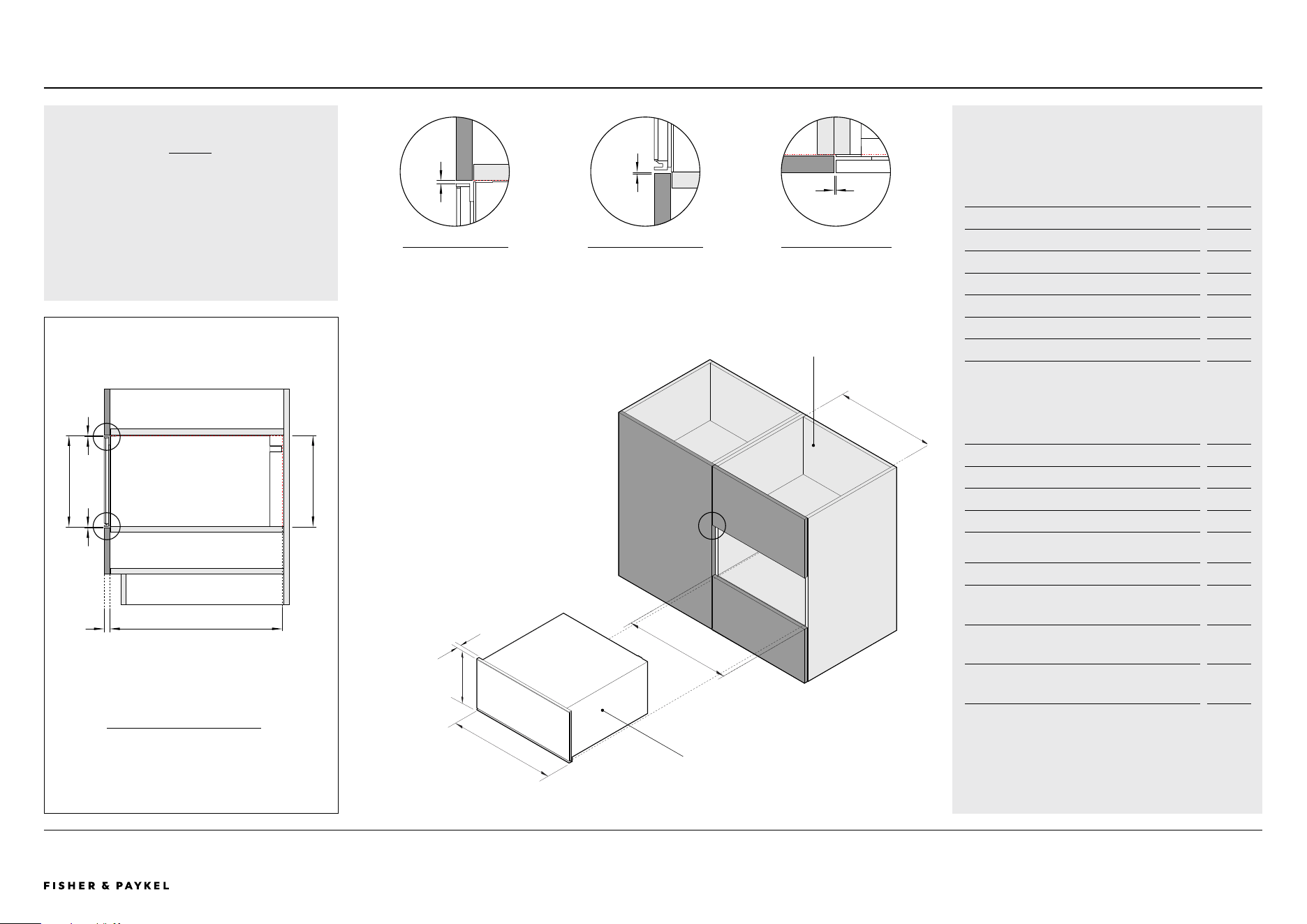
Model no:
Warming Drawer - WB60SMB1-SET, WB60SMG1-SET
Cabinetry Dimensions - Flush
mm
A Overall cabinet height*
144
B Overall cabinet width
600
C Minimum inside width of cavity
560
D Minimum inside height of cavity
142
E Minimum inside depth of cavity
550
F Thickness of cabinetry front panel** 16-20
*Overall cabinet height is overall product height with minimum clearances above
drawer front panel to upper cabinetry front panel
**Cabinetry shown in drawings 19mm panels. If the front panel is thinner than
20mm a rebate for the warming drawer is required to achieve a flush finish
Product Dimensions mm
G Overall height of product 140
H Overall width of product 596
I Thickness of warming drawer front panel and flange 20
Cabinetry Clearances mm
J Minimum clearances above drawer front panel to
upper cabinetry front panel*
4
K Minimum clearances between bottom of drawer
chassis to lower cabinetry front panel
2
L Minimum clearance between adjacent front panel
or appliance
2
*Achieve a smaller gap between drawer front panel to upper cabinetry front panel
by dropping cabinetry front panel down
CABINETRY
PROFILE VIEW
NOTE
The Warming Drawer can fully support a 60cm
Fisher & Paykel oven, without adding a shelf
in between.
BACKFRONT
A
EF
J
K
D
Warming Drawer
H
I
G
WB60SMB1-SET, WB60SMG1-SET
PLANNING CONSIDERATIONS | WARMING DRAWER, 60CM
J
K
L
2
1
3
Closed cabinetry
Warming Drawer
C
B
CLEARANCE ABOVE
PROFILE VIEW
1 2
CLEARANCE BOTTOM
PROFILE VIEW
ADJACENT CABINET
PLAN VIEW
3
<< CONTENTS

The models shown in this Planning Guide may not be available in all markets and are subject to change at any time. Product specifications may vary from those shown. This Planning Guide should not be used as installation guidance for any
product. Further information is required to safely and correctly install the products featured here. Specific installation guidance will be available on our website fisherpaykel.com
© FISHER & PAYKEL LIMITED 2024 PAGE 3790003353D PLANNING GUIDE COOKING - VERSION D - APRIL 2024
Model no:
Vacuum Seal Drawer - VB60SMB1-SET, VB60SMG1-SET
Cabinetry Dimensions - Flush
mm
A Overall cabinet height*
144
B Overall cabinet width
600
C Minimum inside width of cavity
560
D Minimum inside height of cavity
142
E Minimum inside depth of cavity
550
F Thickness of cabinetry front panel** 16-20
*Overall cabinet height is overall product height with minimum clearances above
drawer front panel to upper cabinetry front panel
**Cabinetry shown in drawings 19mm panels. If the front panel is thinner than
20mm a rebate for the vacuum seal drawer is required to achieve a flush finish
Product Dimensions mm
G Overall height of product 140
H Overall width of product 596
I Thickness of vacuum seal drawer front panel and
flange
20
Cabinetry Clearances mm
J Minimum clearances above drawer front panel to
upper cabinetry front panel*
4
K Minimum clearances between bottom of drawer
chassis to lower cabinetry front panel
2
L Minimum clearance between adjacent front panel
or appliance
2
*Achieve a smaller gap between drawer front panel to upper cabinetry front panel
by dropping cabinetry front panel down
NOTE
The Vacuum Seal Drawer can fully support a
60cm Fisher & Paykel oven, without adding a
shelf in between.
Vacuum Seal Drawer
H
I
G
VB60SMB1-SET, VB60SMG1-SET PLANNING CONSIDERATIONS | VACUUM SEAL DRAWER, 60CM
CABINETRY
PROFILE VIEW
BACKFRONT
A
EF
J
K
D
J
K
L
2
1
3
Vacuum Seal Drawer
C
B
Closed cabinetry
CLEARANCE ABOVE
PROFILE VIEW
1 2
CLEARANCE BOTTOM
PROFILE VIEW
ADJACENT CABINET
PLAN VIEW
3
<< CONTENTS

© FISHER & PAYKEL LIMITED 2024 PAGE 3890003353D PLANNING GUIDE COOKING - VERSION D - APRIL 2024
SERVICES
Services
The models shown in this Planning Guide may not be available in all markets and are subject to change at any time. Product specifications may vary from those shown. This Planning Guide should not be used as installation guidance for any
product. Further information is required to safely and correctly install the products featured here. Specific installation guidance will be available on our website fisherpaykel.com
© FISHER & PAYKEL LIMITED 2024 PAGE 3990003353D PLANNING GUIDE COOKING - VERSION D - APRIL 2024
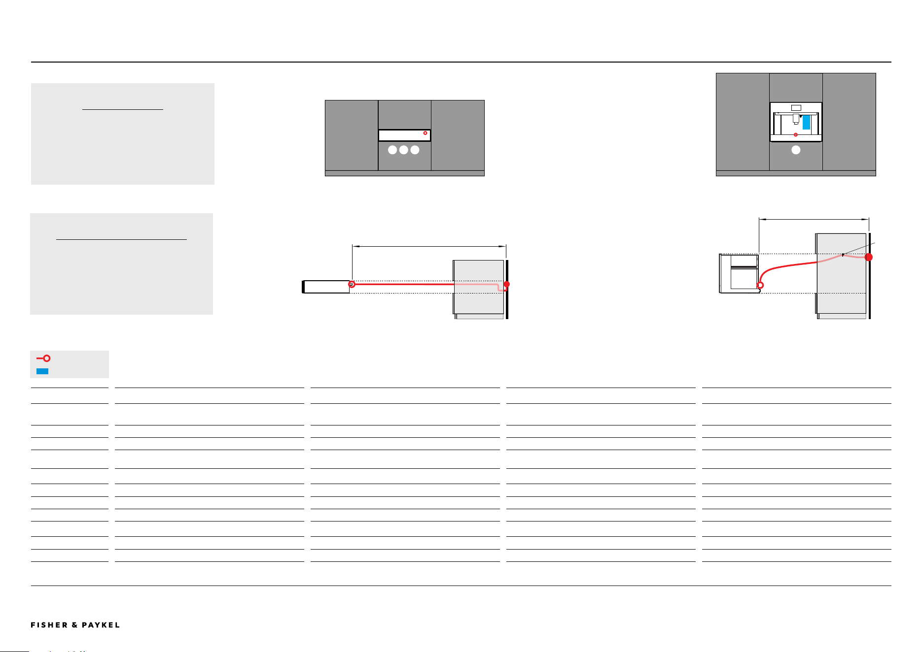
VACUUM SEAL DRAWER
VB60SMB1-SET
VB60SMG1-SET
WARMING DRAWER
WB60SMB1-SET
WB60SMG1-SET
WARMING DRAWER TALL
WB60SMTB1-SET
BUILT-IN COFFEE MAKER
EB60MSB1
EB60MSG1
POWER CORD
Maximum power cord
length*
1800mm 1800mm 1800mm 1700mm
Location Upper right Upper right Upper right Lower centered
Connection Flex cord Flex cord Flex cord Flex cord
*Measured from power outlet
WATE R
Total Capacity - - - 2.4L
Location - - - Water tank (internal)
ELECTRICAL
Supply 220–240 V, 50 Hz 220–240 V, 50 Hz 220–240 V, 50 Hz 220–240 V, 50 Hz
Service 10 A 10 A 10 A 20 A
Note: Multiple product installation requires the design of power outlets according to local regulations.
Clip
provided
BUILT-IN COFFEE MAKER
The power cable must be long enough to
allow the appliance to be extracted from the
cabinet to fill the coffee bean container. Fix
the power cable with the clip.
SERVICES | POWER CORD LENGTH AND LOCATION
Power Cord Length and Location - COMPANIONS
Max 1800mm
Max 1700mm
CONNECTION
Connections may be located in an adjacent
cabinet to either side of the appliance.
Ensure power will remain accessible following
install to allow access for any future product
maintenance.
Power Cable
Water Tank
1 2 3 4
41 2 3
21 3 4
VB60SMB1-SET, VB60SMG1-SET,
WB60SMB1-SET, WB60SMG1-SET, WB60SMTB1-SET,
EB60MSB1, EB60MSG1
<< CONTENTS
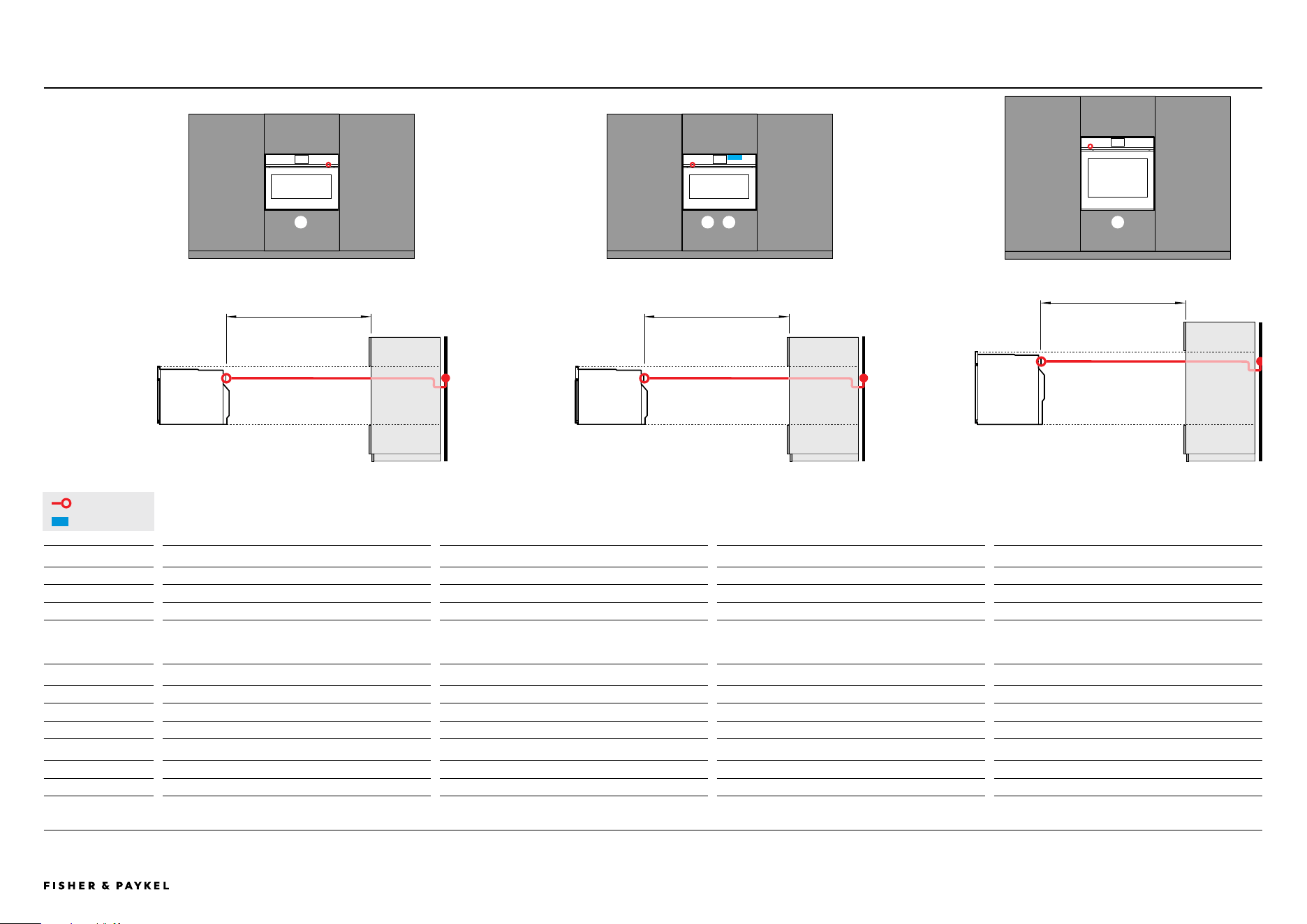
The models shown in this Planning Guide may not be available in all markets and are subject to change at any time. Product specifications may vary from those shown. This Planning Guide should not be used as installation guidance for any
product. Further information is required to safely and correctly install the products featured here. Specific installation guidance will be available on our website fisherpaykel.com
© FISHER & PAYKEL LIMITED 2024 PAGE 4090003353D PLANNING GUIDE COOKING - VERSION D - APRIL 2024
COMBINATION MICROWAVE OVEN
OM60NMTNB1
OM60NMTNG1
COMBINATION STEAM
OVEN
OS60NMTNB1
OS60NMTNG1
COMBINATION STEAM
OVEN
OS60SMTNB1
OS60SMTNG1
OVEN
OB60SMPTNB1
OB60SMPTNG1
POWER CORD
Power cord free length Minimum 1500mm* Minimum 1500mm* Minimum 1500mm* Minimum 1500mm*
Location Upper right Upper left Upper left Upper left
Connection Hard wire** Hard wire** Hard wire** Hard wire**
*The electrician provides sufficient free length of power supply cable to reach from the bottom rear of the cavity to at least 1.5m in front of the bottom edge of the opening
**For more information, refer to the Installation Guide. Ensure power will remain accessible following install to allow access for any future product maintenance.
WATE R
Total Capacity - 1.4L 1.4L -
Location - Water tank (internal) Water tank (internal) -
ELECTRICAL
Supply 220–240 V, 50 Hz 220–240 V, 50 Hz 220–240 V, 50 Hz 220–240 V, 50 Hz
Service 20 A 20 A 20 A 20 A
Note: Multiple product installation requires the design of power outlets according to local regulations.
Minimum 1500mm Minimum 1500mm
Minimum 1500mm
Power Cable
Water Tank
5 6 7 8
5
5 8
OM60NMTNB1, OM60NMTNG1, OS60NMTNB1, OS60NMTNG1,
OS60SMTNB1, OS60SMTNG1, OB60SMPTNB1, OB60SMPTNG1
SERVICES | POWER CORD LENGTH AND LOCATION
Power Cord Length and Location - OVENS
8
76
76
<< CONTENTS

© FISHER & PAYKEL LIMITED 2024 PAGE 4190003353D PLANNING GUIDE COOKING - VERSION D - APRIL 2024