1
User Manual
Article No: RGB-RD-UM-mini-pro E000
Revision No: V1.0

© Xiamen RGBlink Science & Technology Co., Ltd.
Ph: +86 592 5771197 | support@rgblink.com | www.rgblink.com
1
Content
Declarations ...........................................................................................................................................................3
FCC/Warranty............................................................................................................................................................. 3
Operators Safety Summary ........................................................................................................................................ 4
Installation Safety Summary.......................................................................................................................................4
Chapter 1 Your Product ........................................................................................................................................6
1.1 In the Box..............................................................................................................................................................6
1.2 Product Overview .................................................................................................................................................7
Key Features........................................................................................................................................................... 7
Front Panel..............................................................................................................................................................8
Interface Panel........................................................................................................................................................9
Dimension.............................................................................................................................................................10
Chapter 2 Install Your Product ............................................................................................................................. 11
2.1 Plug in Power......................................................................................................................................................11
2.2 Input HDMI Signal Source .................................................................................................................................. 11
2.3 Connecting HDMI Output...................................................................................................................................12
2.4 Connecting Microphone and External Monitoring Devices...............................................................................12
2.5 Connect USB and Webcam.................................................................................................................................13
2.6 Connect Computer............................................................................................................................................. 13
2.7 Turn on Your mini-pro.........................................................................................................................................14
Chapter 3 Use Your Product .................................................................................................................................15
3.1 Touch Screen Operation.....................................................................................................................................15
Touch Screen Introduction................................................................................................................................... 15
Swipe Shortcut......................................................................................................................................................15
Preset Menu ......................................................................................................................................................... 16
3.2 Switch Source..................................................................................................................................................... 16
Switch Effect Setting .............................................................................................................................................16
Switch Mode Setting.............................................................................................................................................17
3.3 T-Bar Switch and Multi-screen Preview.............................................................................................................18
3.4 PIP.......................................................................................................................................................................18
PIP Layout Setting.................................................................................................................................................18
PIP Layer Setting...................................................................................................................................................19
3.4 Views...................................................................................................................................................................19
3.5 Video Output...................................................................................................................................................... 20
HDMI Output........................................................................................................................................................20
USB3.0 Output ......................................................................................................................................................22
3.6 Audio...................................................................................................................................................................22
3.7 Chroma Key.........................................................................................................................................................24

© Xiamen RGBlink Science & Technology Co., Ltd.
Ph: +86 592 5771197 | support@rgblink.com | www.rgblink.com
2
3.9 Record.................................................................................................................................................................26
Chapter 4 Streaming ............................................................................................................................................28
4.1 YouTube Streaming .............................................................................................................................................28
4.2 Facebook Streaming...........................................................................................................................................29
4.3 Zoom Streaming ................................................................................................................................................. 30
4.4 OBS Streaming ....................................................................................................................................................31
4.5 vMix Streaming...................................................................................................................................................35
Chapter 5 XPOSE mini Operation .........................................................................................................................37
5.1 Connect mini-pro and computer........................................................................................................................37
Direct Link via a Network Cable ........................................................................................................................... 37
Static Direct Connection.......................................................................................................................................39
Connect Wirelessly with Your Router...................................................................................................................39
5.2 Using XPOSE mini............................................................................................................................................... 40
Search Device ....................................................................................................................................................... 41
PTZ Camera Setting.............................................................................................................................................. 42
Chroma Key...........................................................................................................................................................43
Live Streaming...................................................................................................................................................... 43
Test Pattern...........................................................................................................................................................44
Password Protection.............................................................................................................................................44
T- Bar Calibration..................................................................................................................................................45
5.3 Upgrade.............................................................................................................................................................. 45
Chapter 6 Ordering Codes ....................................................................................................................................49
6.1 Product Code ......................................................................................................................................................49
Chapter 7 Appendix ............................................................................................................................................. 50
7.1 Specification ....................................................................................................................................................... 50
7.2 FAQ......................................................................................................................................................................51
7.3 Terms & Definitions............................................................................................................................................53
7.4 Revision History..................................................................................................................................................59
Chapter 8 Support ............................................................................................................................................... 60

© Xiamen RGBlink Science & Technology Co., Ltd.
Ph: +86 592 5771197 | support@rgblink.com | www.rgblink.com
3
Thank you for choosing our product!
This User Manual is designed to show you how to use this video processor quickly and make use of all
the features. Please read all directions and instructions carefully before using this product.
Declarations
FCC/Warranty
Federal Communications Commission (FCC) Statement
This equipment has been tested and found to comply with the limits for a class A digital device, pursuant
to Part 15 of the FCC rules. These limits are designed to provide reasonable protection against harmful
interference when the equipment is operated in a commercial environment. This equipment generates,
uses, and can radiate radio frequency energy and, if not installed and used in accordance with the
instruction manual, may cause harmful interference to radio communications. Operation of this equipment
in a residential area may cause harmful interference, in which case the user will be responsible for
correcting any interference.
Guarantee and Compensation
RGBlink provides a guarantee relating to perfect manufacturing as part of the legally stipulated terms
of guarantee. On receipt, the purchaser must immediately inspect all delivered goods for damage
incurred during transport, as well as for material and manufacturing faults. RGBlink must be informed
immediately in writing of any complains.
The period of guarantee begins on the date of transfer of risks, in the case of special systems and
software on the date of commissioning, at latest 30 days after the transfer of risks. In the event of justified
notice of compliant, RGBlink can repair the fault or provide a replacement at its own discretion within an
appropriate period. If this measure proves to be impossible or unsuccessful, the purchaser can demand a
reduction in the purchase price or cancellation of the contract. All other claims, in particular those relating
to compensation for direct or indirect damage, and also damage attributed to the operation of software as
well as to other service provided by RGBlink, being a component of the system or independent service,
will be deemed invalid provided the damage is not proven to be attributed to the absence of properties
guaranteed in writing or due to the intent or gross negligence or part of RGBlink.
If the purchaser or a third party carries out modifications or repairs on goods delivered by RGBlink, or if
the goods are handled incorrectly, in particular if the systems are commissioned operated incorrectly or if,
after the transfer of risks, the goods are subject to influences not agreed upon in the contract, all
guarantee claims of the purchaser will be rendered invalid. Not included in the guarantee coverage are
system failures which are attributed to programs or special electronic circuitry provided by the purchaser,
e.g. interfaces. Normal wear as well as normal maintenance are not subject to the guarantee provided by
RGBlink either.
The environmental conditions as well as the servicing and maintenance regulations specified in this
manual must be complied with by the customer.

© Xiamen RGBlink Science & Technology Co., Ltd.
Ph: +86 592 5771197 | support@rgblink.com | www.rgblink.com
4
Operators Safety Summary
The general safety information in this summary is for operating personnel.
Do Not Remove Covers or Panels
There are no user-serviceable parts within the unit. Removal of the top cover will expose dangerous
voltages. To avoid personal injury, do not remove the top cover. Do not operate the unit without the cover
installed.
Power Source
This product is intended to operate from a power source that will not apply more than 230 volts rms
between the supply conductors or between both supply conductor and ground. A protective ground
connection by way of grounding conductor in the power cord is essential for safe operation.
Grounding the Product
This product is grounded through the grounding conductor of the power cord. To avoid electrical shock,
plug the power cord into a properly wired receptacle before connecting to the product input or output
terminals. A protective-ground connection by way of the grounding conductor in the power cord is
essential for safe operation.
Use the Proper Power Cord
Use only the power cord and connector specified for your product. Use only a power cord that is in good
condition. Refer cord and connector changes to qualified service personnel.
Use the Proper Fuse
To avoid fire hazard, use only the fuse having identical type, voltage rating, and current rating
characteristics. Refer fuse replacement to qualified service personnel.
Do Not Operate in Explosive Atmospheres
To avoid explosion, do not operate this product in an explosive atmosphere.
Installation Safety Summary
Safety Precautions
For all product installation procedures, please observe the following important safety and handling rules
to avoid damage to yourself and the equipment.
To protect users from electric shock, ensure that the chassis connects to earth via the ground wire
provided in the AC power Cord.
The AC Socket-outlet should be installed near the equipment and be easily accessible.

© Xiamen RGBlink Science & Technology Co., Ltd.
Ph: +86 592 5771197 | support@rgblink.com | www.rgblink.com
5
Unpacking and Inspection
Before opening product shipping box, inspect it for damage. If you find any damage, notify the shipping
carrier immediately for all claims adjustments. As you open the box, compare its contents against the
packing slip. If you find any shortages, contact your sales representative.
Once you have removed all the components from their packaging and checked that all the listed
components are present, visually inspect the system to ensure there was no damage during shipping. If
there is damage, notify the shipping carrier immediately for all claims adjustments.
Site Preparation
The environment in which you install your product should be clean, properly lit, free from static, and have
adequate power, ventilation, and space for all components.
© Xiamen RGBlink Science & Technology Co., Ltd.
Ph: +86 592 5771197 | support@rgblink.com | www.rgblink.com
6
Chapter 1 Your Product
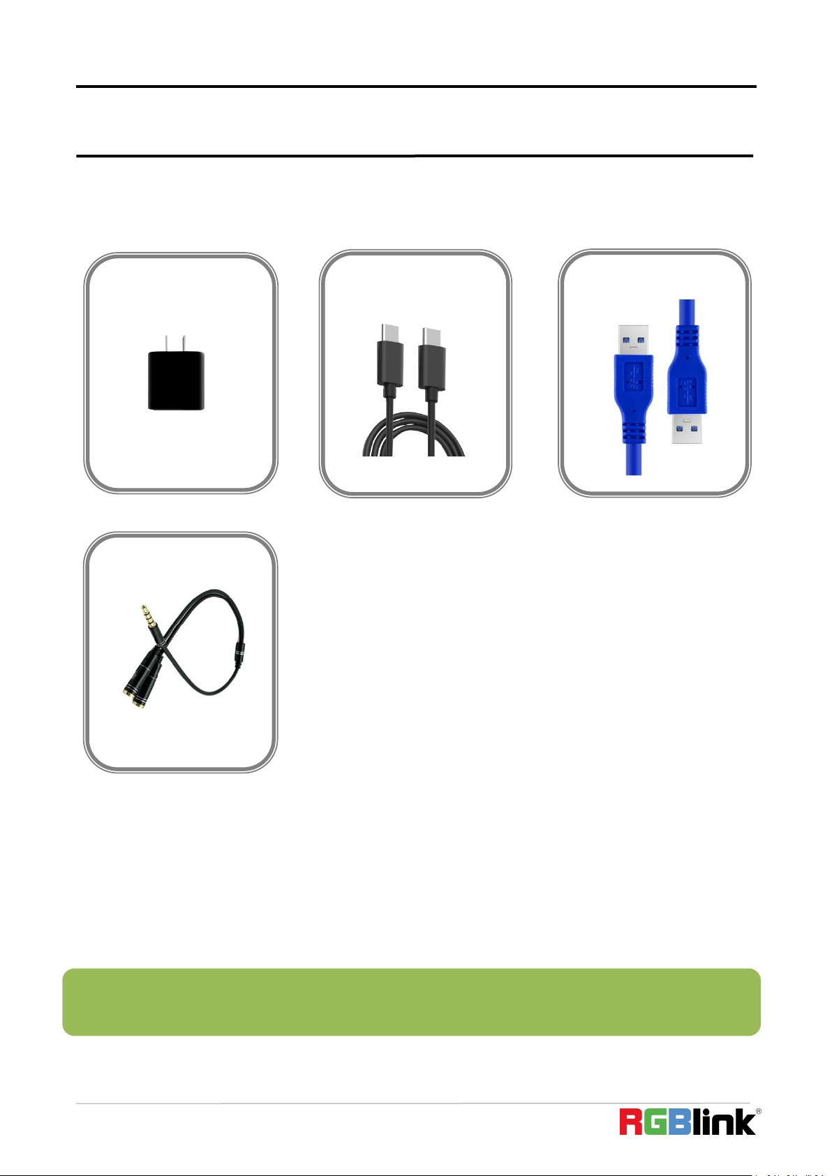
1.1 In the Box
USB3.0 Cable
Power Adapter
Note: For computers/phones/pads without HDMI port but with Type C interface, you can convert Type C to
HDMI. Be sure that the Type C interface shall meet the USB 3.1 standard.
Type-C Cable
Audio Cable
© Xiamen RGBlink Science & Technology Co., Ltd.
Ph: +86 592 5771197
7
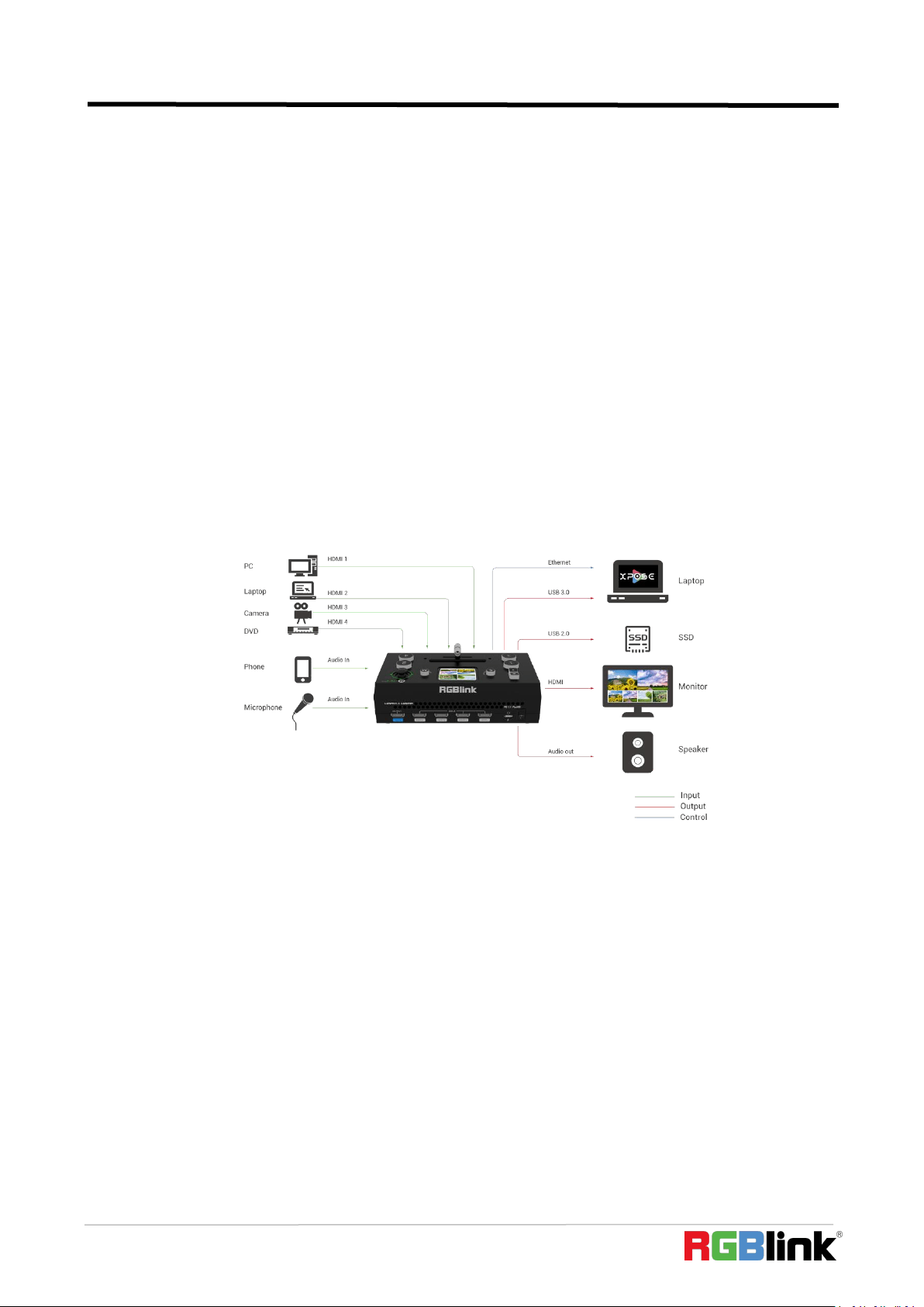
1.2 Product Overview
The dual channel video switcher mixer for the streaming generation, mini-pro features four resolution
independent inputs - connect 2K or 4K signals up to 4K60 to take advantage of native high-performance sources,
whether cameras or laptops, without compromise.
While presets for PIP and PBP are provided, mini-pro includes full pixel-to-pixel scaling capabilities for both
the PIP and background video layers–truly unique in a streaming mixer of this size – features usually found
only on larger professional video mixers.
Audio for output is selectable from embedded sources or an external source. Both Line and Mic level audio a
supported on aboard with variable delay controls to bring audio into sync if needed.
In addition to HDMI and USB3.0 streaming outputs, mini-pro includes a dedicated USB recording port. Simply
connect a portable drive and record directly from mini-pro.
The exclusive integral display not only shows video preview, but is touch enabled for natural operation of
features and settings. Remote control is available via free companion apps for laptops and mobile devices too.
mini-pro is packed with features including dynamic output control, preview multi-view, picture in picture,
Chroma Key, video transitions, on board PTZ camera controls and more.
Key Features
● mini switcher convenient to carry
● Built-in LCD for video previews
● Joystick Camera Control
● T-Bar switch and 14 transition effects
● 4K HDMI inputs
● support live streaming via USB 3.0
● support recording via USB 2.0
● Embedded & Insert Audio with Sync
© Xiamen RGBlink Science & Technology Co., Ltd.
Ph: +86 592 5771197
8
● Mix audio from multiple inputs
● Chroma Key
● Configurable PIP video overlay
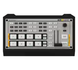
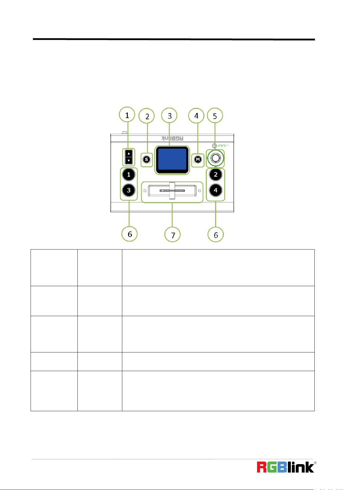
Front Panel
1
Up/Down
1. Adjust volume of PGM when it is under Main menu
2. Proportionally adjust size of sub-picture when it is under position and
scale adjustment
3. Zoom in/out when PTZ control is enabled
2
S
Shortcut button, push it and touch screen enter quick operation interface
which includes 4 Preset to load, Audio,Record on/off,Mute on/off,Chroma
Key on/off
3
2” Touch
Screen
1. Operate mini-pro menu by tapping it and monitor 4 inputs in real time
2. Monitor the screen of the currently controlled camera in real time
under PTZ control, and save the currently set screen by tapping it, and a
call button can be formed on the screen
4
M(menu)
Main menu button, push it and touch screen back to main menu interface
and push it again touch screen display 4 inputs
5
5-Direction
Joystick
1. left-right-up- down 4 directions to choose icons on menu and middle to
confirm entering next level
2. Move the sub-picture when it is under position adjustment
3. Control left right up and down movement when PTZ control is enabled.
© Xiamen RGBlink Science & Technology Co., Ltd.
Ph: +86 592 5771197
9
2
3
4
5
6
7
8
9
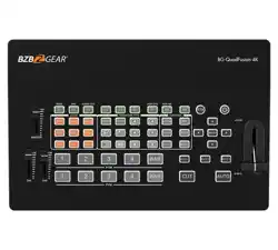
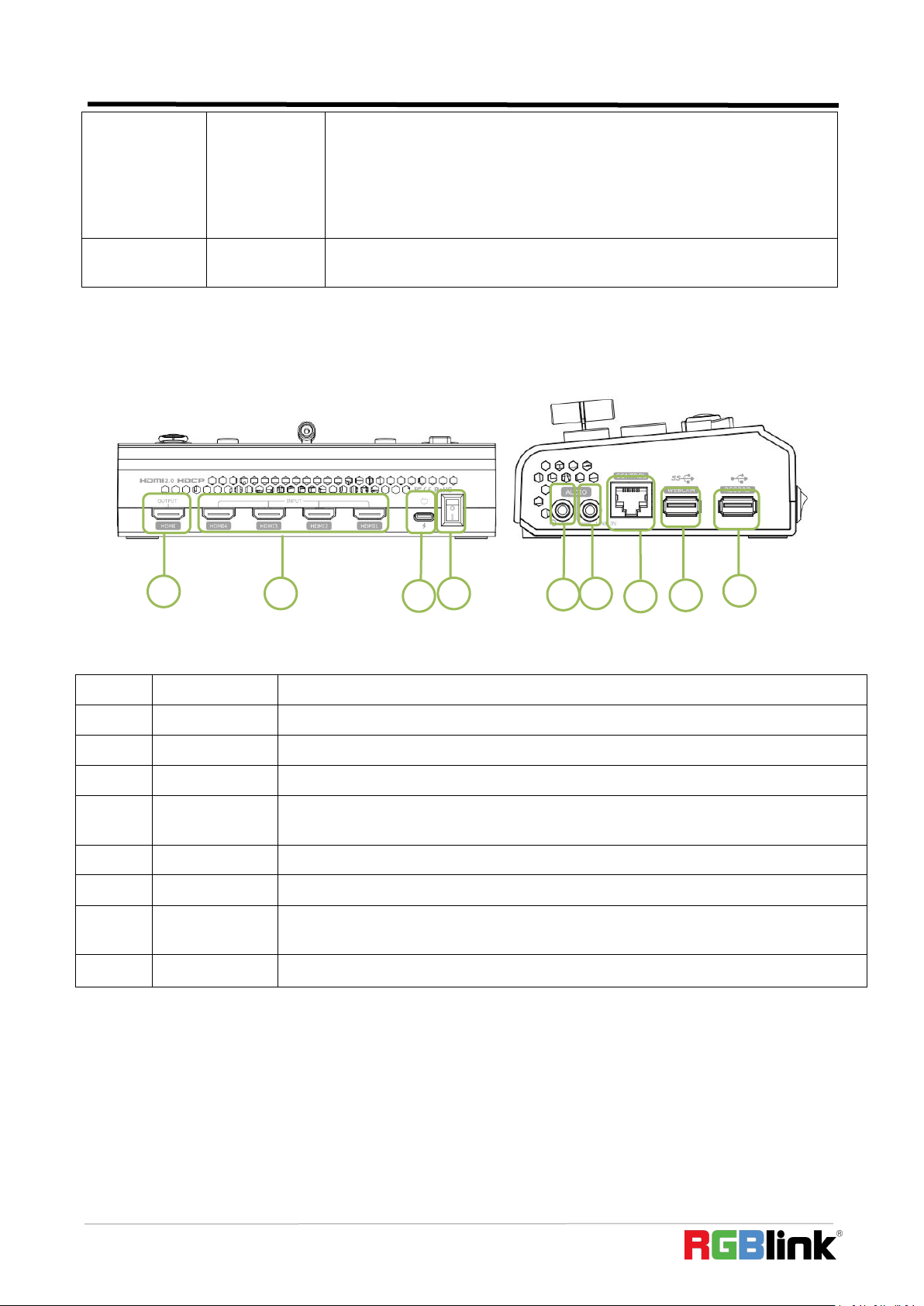
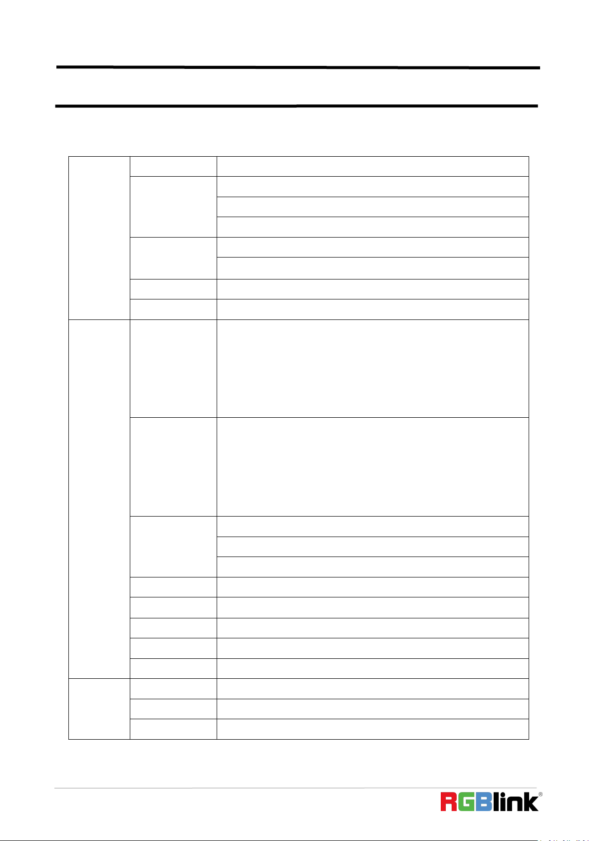
Interface Panel
1
HDMI OUT
1 HDMI Output port, connect to display to show Preview (6 pictures) or PGM.
2
HDMI IN
4 HDMI 4K Inputs, connect to input source from 4K or HD camera or PC
3
Type C
1 Type C Jack for power input, connect to PD power adapter
4
Power
Switch on to power on mini-pro
5
MIC IN &
AUDIO OUT
MIC IN & AUDIO OUT, support one passive MIC input and one audio output via 2 in 1
audio splitter cable
6
LINE IN
LINE IN, active audio input, connect to mobile phone, computer or audio console
7
CONTROL
Communication port to link dedicated software for control
8
WEBCAM
USB output, capture signal via third party streaming software and push to live
broadcasting websites, support access to smart phones for mobile pushing stream
9
RECORD
Connect to SSD to record audio and video from PGM
6
①②③④
4 inputs,
red: on air (PGM)
static green: signal is standing by
flashing green: ready to be switched
No light: input source is not supported or no input source
7
T-Bar
Manual switch, push to left end or right end to switch signal to PGM. T-Bar
is not at end position input switch will fail
1
© Xiamen RGBlink Science & Technology Co., Ltd.
Ph: +86 592 5771197
10
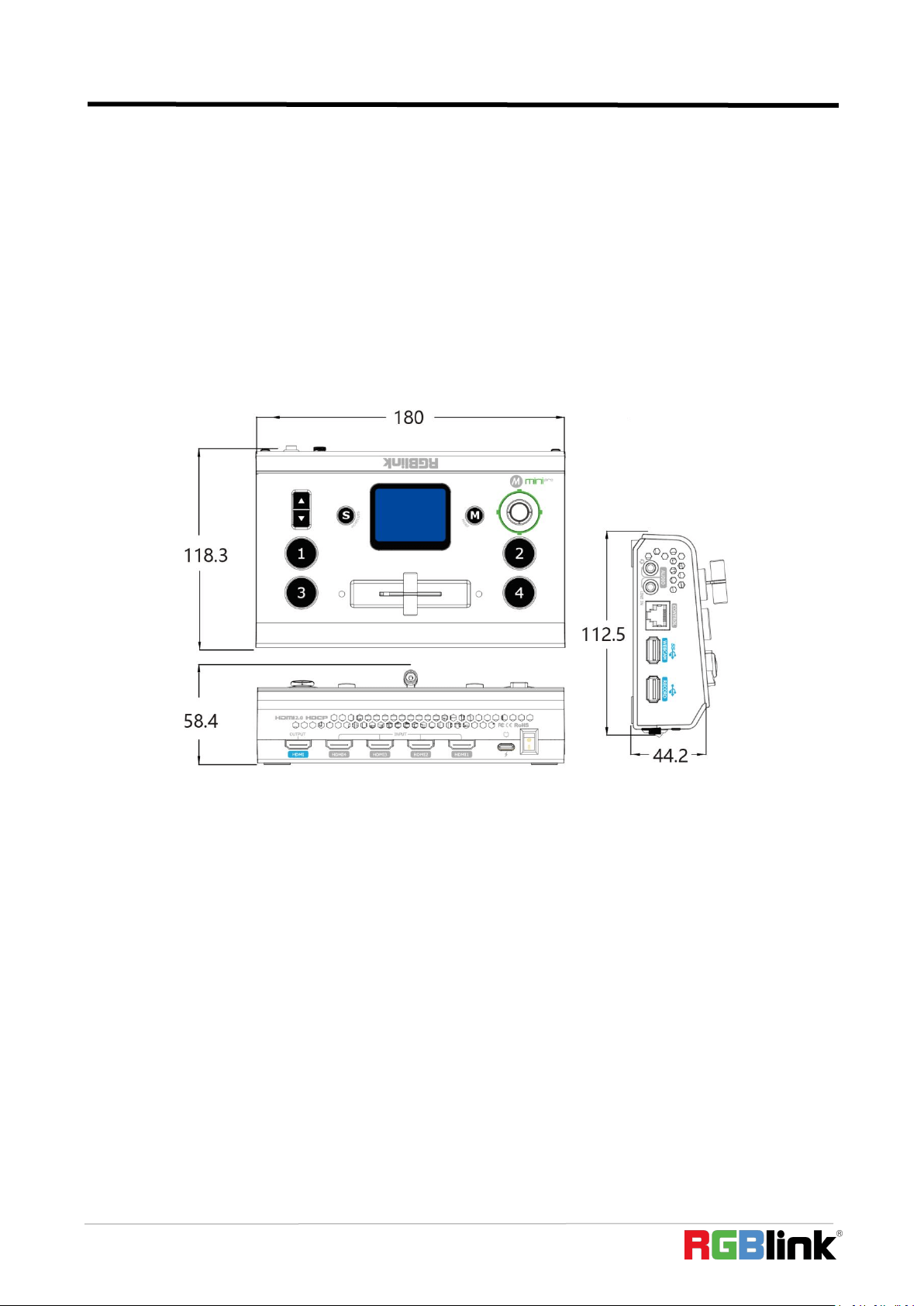
Dimension
Following is the dimension of mini-pro for your reference:
180mm×118.3mm×58.4mm
© Xiamen RGBlink Science & Technology Co., Ltd.
Ph: +86 592 5771197
11
Chapter 2 Install Your Product
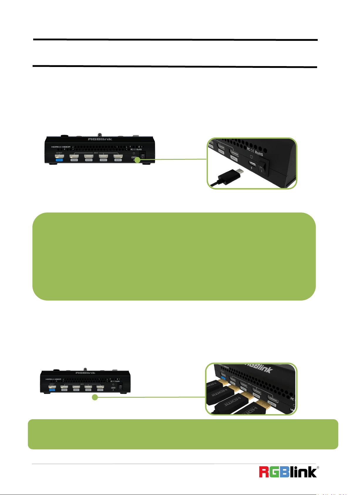
2.1 Plug in Power
RGBlink mini-pro is packaged with a 12V power link cable and Type C power Adapter.
When linking the power supply, please check the power supply standard used in your
country/region.
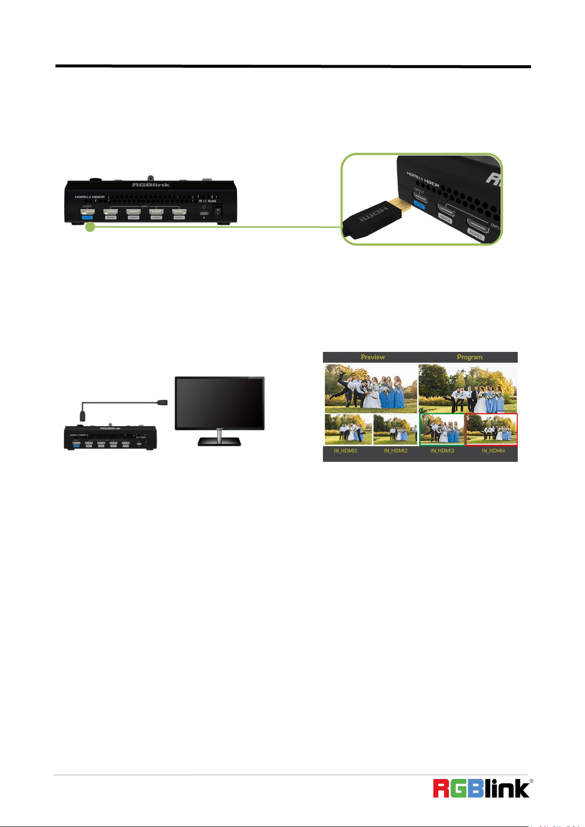
2.2 Input HDMI Signal Source
You can use any camera, computer or other HDMI device as the input source of the mini-pro. It
supports up to 4 sources of different formats and resolutions at the same time via 4 HDMI ports,
and 4 HDMI inputs support up to 4K@60Hz. If you are using interlaced signal, mini-pro supports
de-interlacement through HDMI 1 automatically. You can see the resolution of the input signal on
the mini-pro screen when there is active signal plug in.
Connect mini-pro to power plug by the link cable
Note: The HDMI cable is not included in the mini-pro package and needs to be purchased separately. Some camcorders
use a mini HDMI port, you need to buy a mini HDMI-HDMI cable separately when you use these camcorders.
Note:
The Power Supply included with mini-pro is the recommended power supply for use with the device.In the
event the power supply is mislaid or otherwise not available, a USB-C power supply may be used provided
that the power supply :
1. meet s the USB Power Delivery (PD3.0) specification
2.has a "Fast Charge" capability
3.is rated for a minimum of 20W
and if a replacement USB-C cable is also needed,
4.a only a certified PD aware USB cable should be used
© Xiamen RGBlink Science & Technology Co., Ltd.
Ph: +86 592 5771197
12
2.3 Connecting HDMI Output
You can use an HDMI cable to connect the HDMI output to a monitor with an HDMI input
interface, so that you can monitor the input, output and audio display in real time.
The default output of HDMI output is multi-screen PVW (Preview) monitoring screen, so you
can see the audio and video conditions of all input signal sources, you can see the current status of
each function of mini-pro, and you can also see the PST (Preset) and current PGM (program)output.
In addition to supporting multi-screen monitoring, HDMI output also supports single screen
display of any one of the four inputs. You can switch between PVW and PGM In【Video Output】
menu.
HDMI output supports resolution setting . After pressing the【 M】button, tap the OUTPUT
setting on the menu to select the output resolution format. HDMI output supports resolution up to
1080p60.
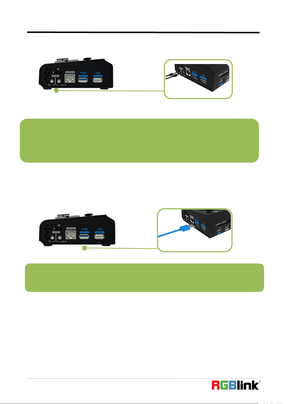
2.4 Connecting Microphone and External
Monitoring Devices
On the right panel of mini-pro,there is a 3.5mm standard microphone interface which can be
directly connect to the microphone or wireless MIC, or LINE output from the external audio console
to do audio mixing of multiple external audio inputs.
The mini-pro supports 3.5mm analog audio and 4-channel HDMI digital audio for
multi-channel simultaneous mix in to make sure sound of the computer and the sound of the MIC
can be output at the same time.
You can use external speakers or headphones to monitor the main output audio signal in real
© Xiamen RGBlink Science & Technology Co., Ltd.
Ph: +86 592 5771197
13
time.
2.5 Connect USB and Webcam
Connect the USB 3.0 port on mini-pro to computer by USB 3.0 cable (blue) and computer will
capture mini-pro USB output as a webcam source which can be pushed to Facebook,YouTube,Zoom,
Twitter and other streaming media platform.
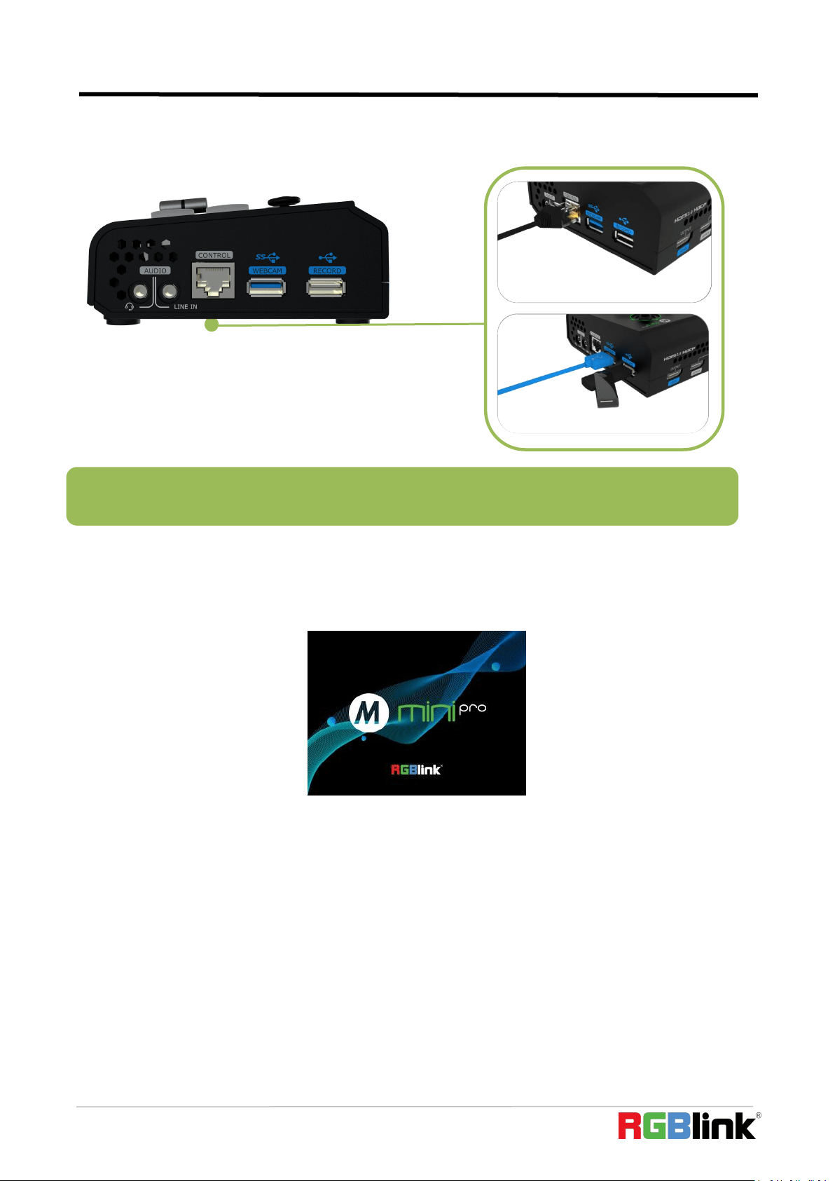
2.6 Connect Computer
Software control:connect computer and mini-pro with CAT6 cable
Record and Stream:connect mini-pro’s USB-A and mini-pro’s USB 3.0 port with USB3.0 cable
(Note:the color of USB3.0 port is blue)
Minimum System Requirements for macOS
● macOS 11.0 Big Sur or later
● macOS 10.15 Catalina
Minimum System Requirements for Windows
Note:If your computer only has a Type-C port, you can use a USB-A to Type-C cable to transmit the webcam
signal. Please note that the Type-C cable you choose needs to support data transmission. The signal is
recognized in Windows and MAC system as「RGBlink USB 3.0 Capture」.
Note: For general camera, there usually is a certain delay due to the processing of light-to-electricity conversion
during the filming process but the processing of MIC is relatively simple,so there will be video picture failing to
keep up with MIC audio, which is synchronization problem. Therefore, it is necessary to do audio delay setting
for the MIC audio to ensure the synchronization of the picture and the sound, which will be explained in the
introduction of "Audio Control" later.
© Xiamen RGBlink Science & Technology Co., Ltd.
Ph: +86 592 5771197
14
● Microsoft Windows 10 64-bit
2.7 Turn on Your mini-pro
After mini-pro is connected to power supply, push the Power button on the rear panel,the
device will enter to the boot interface and enter operation interface within 10S.
Note:The IP address of the mini-pro must be in the same LAN segment as the computer. Refer to 5.1 for IP
address manually changing IP address.
© Xiamen RGBlink Science & Technology Co., Ltd.
Ph: +86 592 5771197
15
Chapter 3 Use Your Product
After system connection of mini-pro to power supply, input source devices(computer,
MIC(camera) and output to HDMI display and USB 3.0 streaming which is recognized as webcam
source on computer.
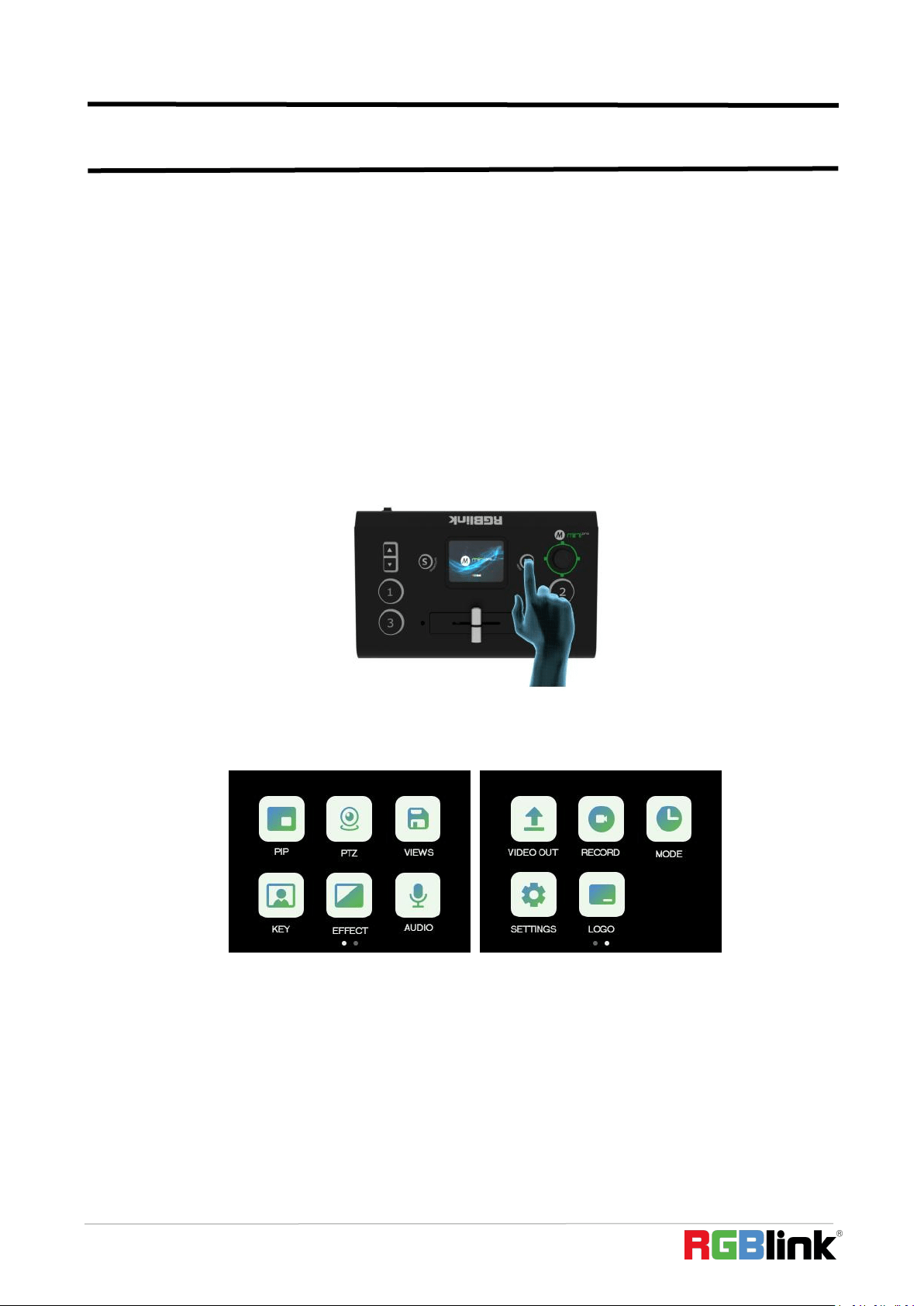
3.1 Touch Screen Operation
Touch Screen Introduction
There is a 2” touch screen on mini-pro operation board, through which most operation can be
done, so let’s introduce this touch screen first.
Before introducing the operation of the touch screen, we need to introduce the button
【M】,the MENU and back key. Push the button and the 2-inch LCD screen will quickly return to the
main menu interface.
As shown in the figure below, the UI style on the touch screen is similar to current smart phone
operating interface. The first-level menu is in icon. You can quickly enter the corresponding function
management interface by tapping the corresponding icon.
Swipe Shortcut
Similarly, the mini-pro's touch screen also has some simple swipe shortcut functions:
© Xiamen RGBlink Science & Technology Co., Ltd.
Ph: +86 592 5771197
16
(1) you can quickly return to the main menu by swiping from bottom to top (same as the【M】
key);
(2) back to last menu by swiping from left to right;
(3) enter the preset Load menu by swiping from top to bottom(same as the【S】key);
(4) enter more settings of current function by swiping from right to left.
When entering an operation item, such as adjusting the transition time, you can adjust it by
sliding the time bar on the screen, or by pushing the up and down keys on the left of the operation
board.
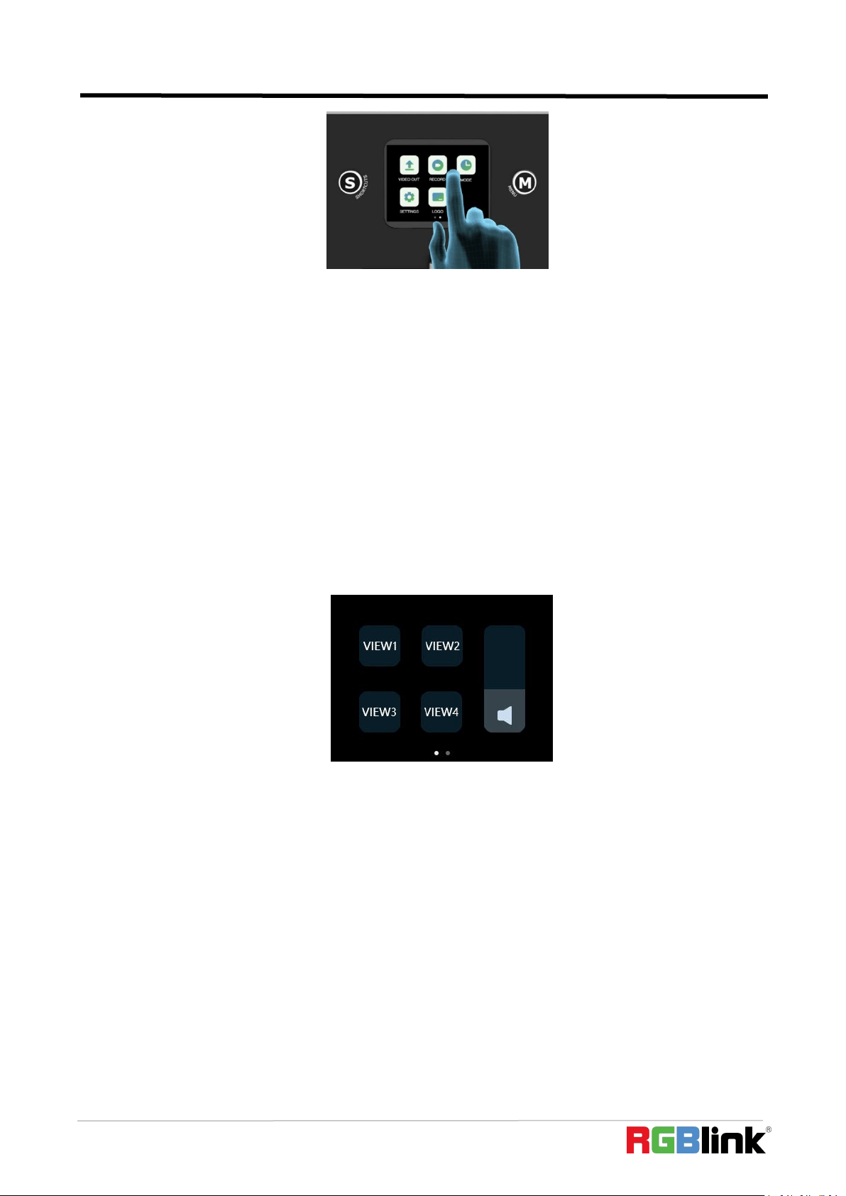
Preset Menu
In the preset menu (by pressing the【S】button or swiping from the top to the bottom of the
screen), the icons on the LCD screen default to the dark off state. Tap the icon to turn to the bright
color to get it selected and open preset (View), Chroma Key switch, Black switch , Record switch,
Mute switch, volume adjustment switch, etc.
The function of the icon button in the shortcut menu can be customized according to user’s needs.
3.2 Switch Source
The buttons ①②③④ on the operation board corresponds to the 4 HDMI inputs one-to-one.
When four signal source plug in, the lights on the signal source buttons will appear in four
states:
Steady green: The signal is recognized and no operation is performed;
Flashing green: The currently selected signal is ready to be switched;
Steady red: The current signal is in PGM output;
Unlit: No signal source is connected or the resolution of the signal source connected is not
accepted.
Switch Effect Setting
mini-pro is default 0.5S Fast Fade mode, by pushing ①②③④ signal buttons, 4 input signals
© Xiamen RGBlink Science & Technology Co., Ltd.
Ph: +86 592 5771197
17
can be switched in fast fade mode.
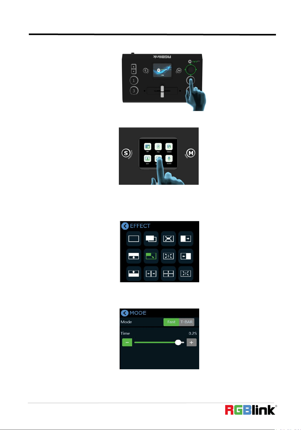
If you want to use more transition effects, tap【EFFECT】icon on the touch screen.
You can enter the【 Effects】 selection interface, where fade in, fade out and various other
transition effects can be selected. The inside icons on the menu can be dragged and sorted
according to your preferences. When the selection is completed, the root directory icon will be
replaced with the last selected icon.
Switch Mode Setting
Tap the icon【MODE】to customized by sliding the time bar.
© Xiamen RGBlink Science & Technology Co., Ltd.
Ph: +86 592 5771197
18
3.3 T-Bar Switch and Multi-screen Preview
mini-pro defaults to Fast Switching Mode, but on some important occasions, you may need to
preview and preset the next scene to ensure the accuracy and stability of the screen.mini-pro
provides T-Bar mode to allow switch after editing and confirmation.
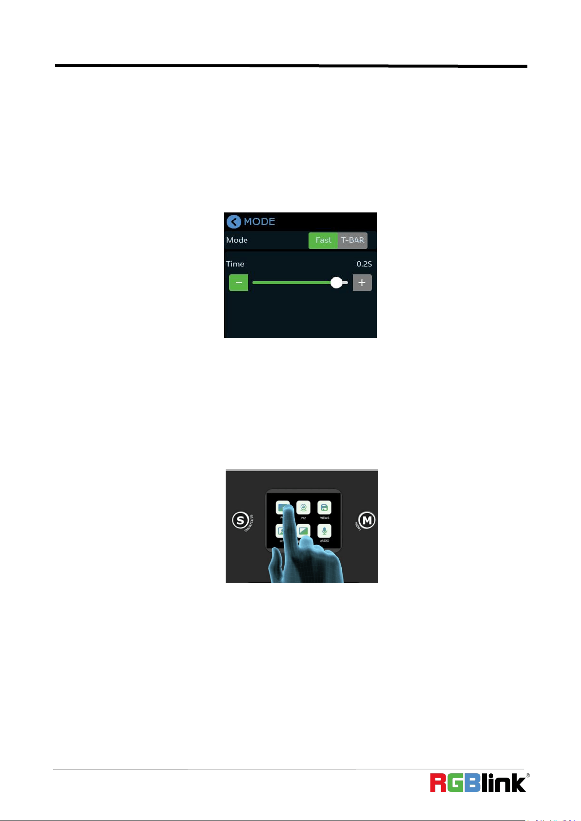
Return to the main menu interface by pushing the button【M】,find the【MODE】icon by swiping
the screen left right, and then tap the icon to enter the menu and you can see【Mode】in which
there options of Fast and T-Bar mode, as follows
When T-Bar is enabled, all operation could be checked on PST window. Slide T-Bar to switch
between PST and PGM.
3.4 PIP
mini-pro defaults to single-screen switching. If you need to use PIP, push button【M】to return
to the main menu, then find【PIP】, and tap the icon to enter the PIP setting interface.
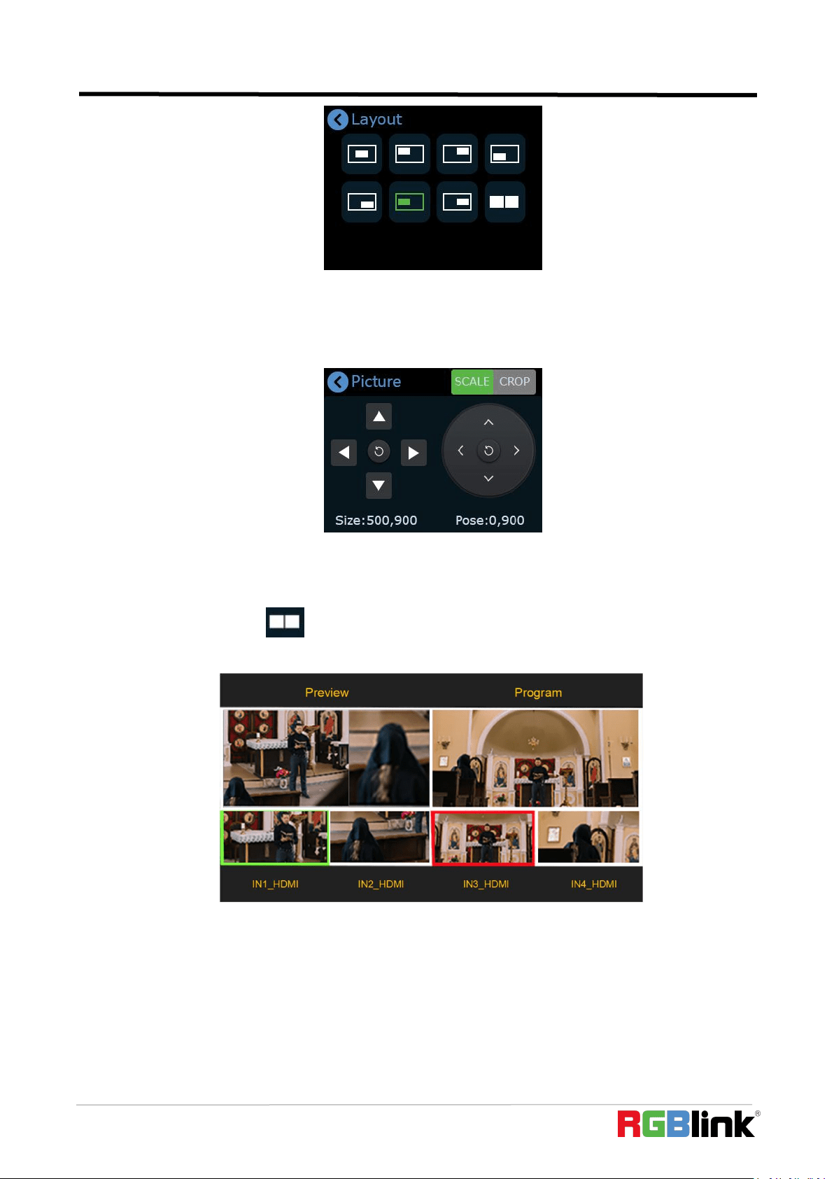
PIP Layout Setting
Layout offers 8 layout options for picture-in-picture. Click the arrow on the right to enter layout
interface and choose the layout needed.
© Xiamen RGBlink Science & Technology Co., Ltd.
Ph: +86 592 5771197
19
PIP Layer Setting
If detailed adjustment is required, return to PIP【Picture】menu,adjust the size and position via
the up/down/left/right keys,as shown below.
In addition to adjustment by moving the slide rail, you can also use the toggle to quickly adjust
the size of the sub-picture, and use the joystick to quickly adjust the position of the sub screen. If
you need to quickly switch to the PGM, you can press the joystick.
If you select the layout ,then press the toggle to adjust the picture ratio and get a better
view.
3.4 Views
mini-pro save preset to View in real time. If you want to quickly load current preset next time,
just save it to corresponding View. The View will save all the currently set parameters including PIP
layout, Chroma Key setting, PTZ presets, therefore when you need to load any preset, just push
corresponding View button in Shortcut interface.
(1) After setting the effect, please tap the button【M】and find the VIEWS.
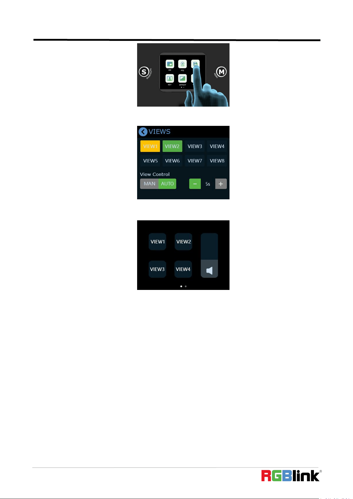
© Xiamen RGBlink Science & Technology Co., Ltd.
Ph: +86 592 5771197
20
(2) By tapping the icon VIEW , you can save the preset to the corresponding View 1-8.
Yellow icon indicates the view that being used,green one is saved views,gray one in the blank view.
(3) Push button【S】to enter the Shortcut menu where there are buttons of View 1~4 which can
loaded directly.
(4) After loading View, if PIP layout needs to change, users can select main screen or sub
screen by pushing the middle button on joystick which default selects sub screen. After selecting
sub screen or main screen, select input source for them by pushing the signal source button, adjust
sub screen size by pushing button Up/Down and position by joystick. All the setting is saved to in
real time to make sure it can be used next time the device is turned on.
(5) If you want the modified preset to be loaded from the View, you need to re-save it to the
current View or a new View. Please repeat the above save operation.
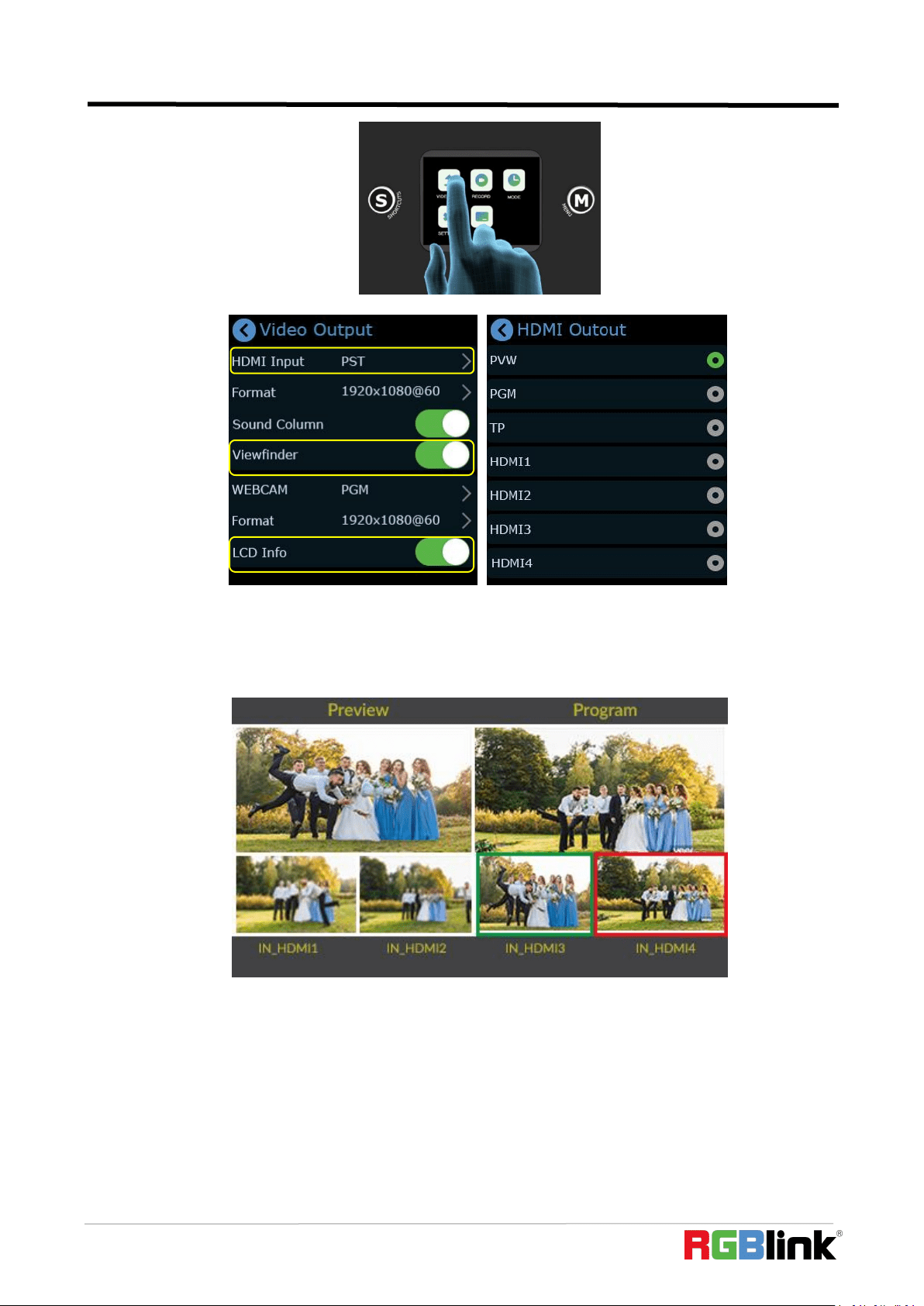
3.5 Video Output
mini-pro offers output through HDMI and USB.
HDMI Output
HDMI output defaults multi-screen preview,which can be switched to PGM or the 4 input
content in field application.
Push button【M】to return to main menu and find【Video Output】to set parameters for the
HDMI output.
© Xiamen RGBlink Science & Technology Co., Ltd.
Ph: +86 592 5771197
21
Push button【M】again when the touch screen is in main menu interface and touch screen will
enter 4-screen input source preview.
Turn on【Viewfinder】, you can see a white rectangle in the PST as shown in the picture,helping
users frame the camera view.
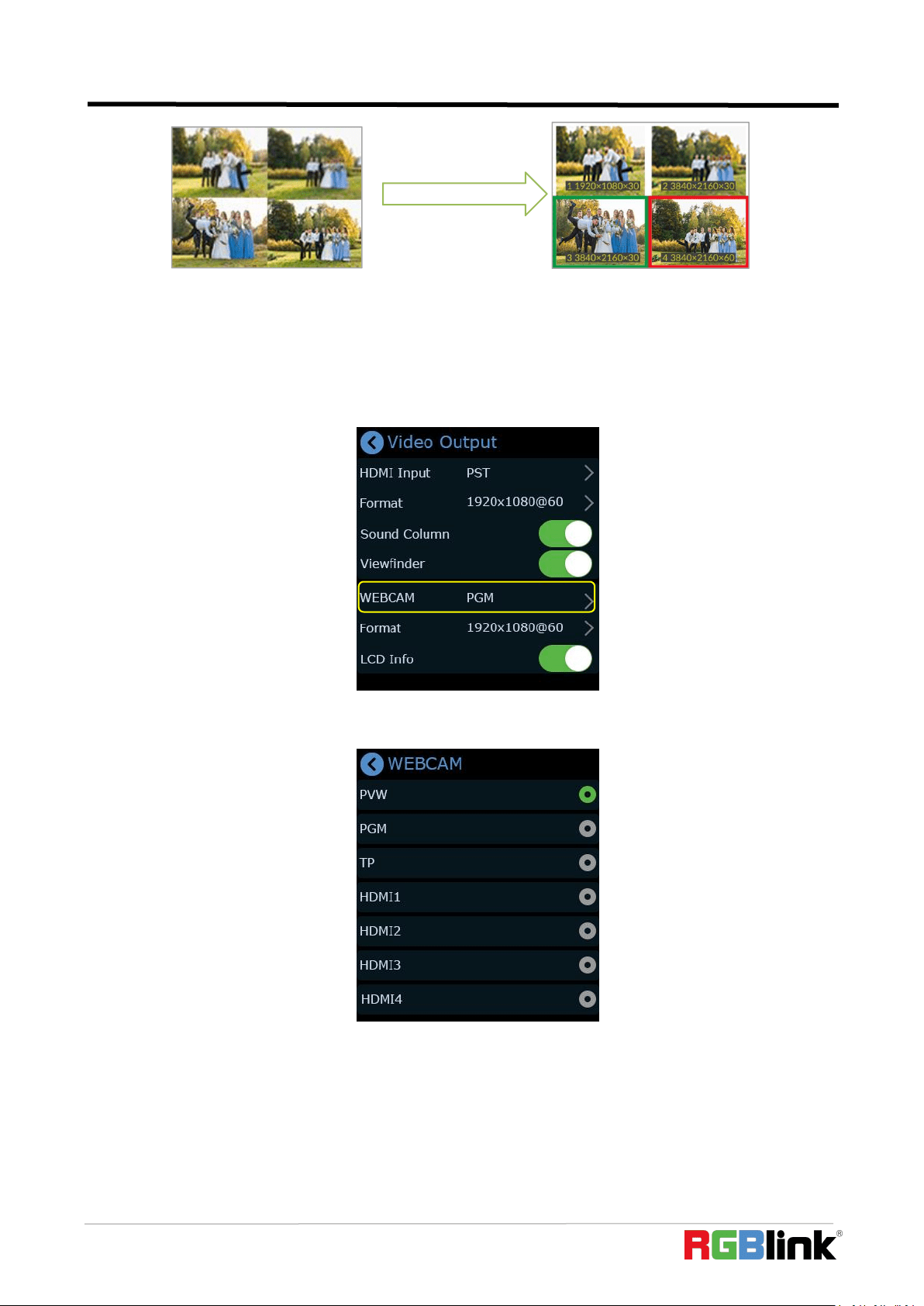
The【LCD Info】is LCD display setting, which controls whether the 2x2 video preview is【simple】
or as 【standard(PVW)】,turn on【LCD Info】to check the resolution of four inputs as shown in the
picture below:
© Xiamen RGBlink Science & Technology Co., Ltd.
Ph: +86 592 5771197
22
USB 3.0 Output
USB 3.0 output recognized as WEBCAM on computer defaults to be PGM which can be changed
to multi-screen PST or TP (Test Pattern).
Push button【M】to return main menu and find【Output】to do WEBCAM setting.
It is default to be PGM and tap “>”on the right to change to PST or TP. Choose format for the
output setting by tapping “>”on the right.
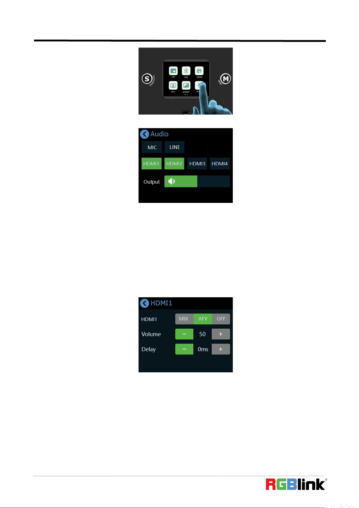
3.6 Audio
mini-pro supports mixed output of multiple channels, and also supports audio delay.
Tap the button【M】to return to the main menu, find and tap【Audio】to enter the sound setting
interface.
Turn on
Simple
Standard
© Xiamen RGBlink Science & Technology Co., Ltd.
Ph: +86 592 5771197
23
The audio output can be turned on or off, and the volume can be adjusted by sliding the bar.
The audio input can be selected as MIC passive microphone input, or LINE input audio console
or active microphone signal input according to needs.
The four HDMI input ports all support embedded audio. Turn on the MIX to always add the
audio to PGM.
Turn on AFV, the audio follows the video switch to perform a soft gradual transition when video
is switched.
If the sound and the video are not synchronous, increase or reduce the Delay value under AFV .
Generally speaking, the sound of the MIC is about 100ms faster than the HDMI picture, so the delay
of the MIC can be adjusted between 80-115ms.(External and HDMI input audio support delay up to
160ms)
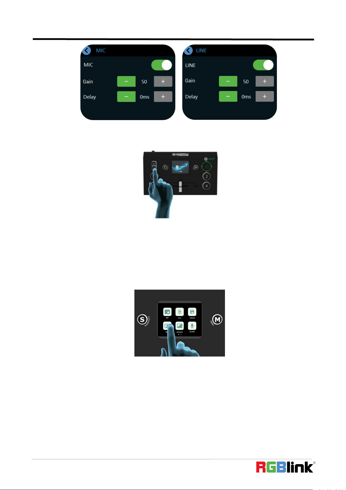
Users can also click【MIC】/【LINE】in 【AUDIO】interface to do the follwoing setting.
MIC / LINE: ON/OFF
Gain: 0-100
Delay: 0-160ms
© Xiamen RGBlink Science & Technology Co., Ltd.
Ph: +86 592 5771197
24
When the touch screen is in the main interface or preview interface (4-screen of the 4 inputs)
or Shortcut interface, the PGM audio volume can be adjusted by the toggle.
3.7 Chroma Key
mini-pro supports matting, the Chroma Key in the menu, removing the pure color background
and overlaying it on another signal to realize the application of virtual reality. Matting can be done
on XPOSE mini or simple settings and adjustments can be made on the Chroma Key in the menu.
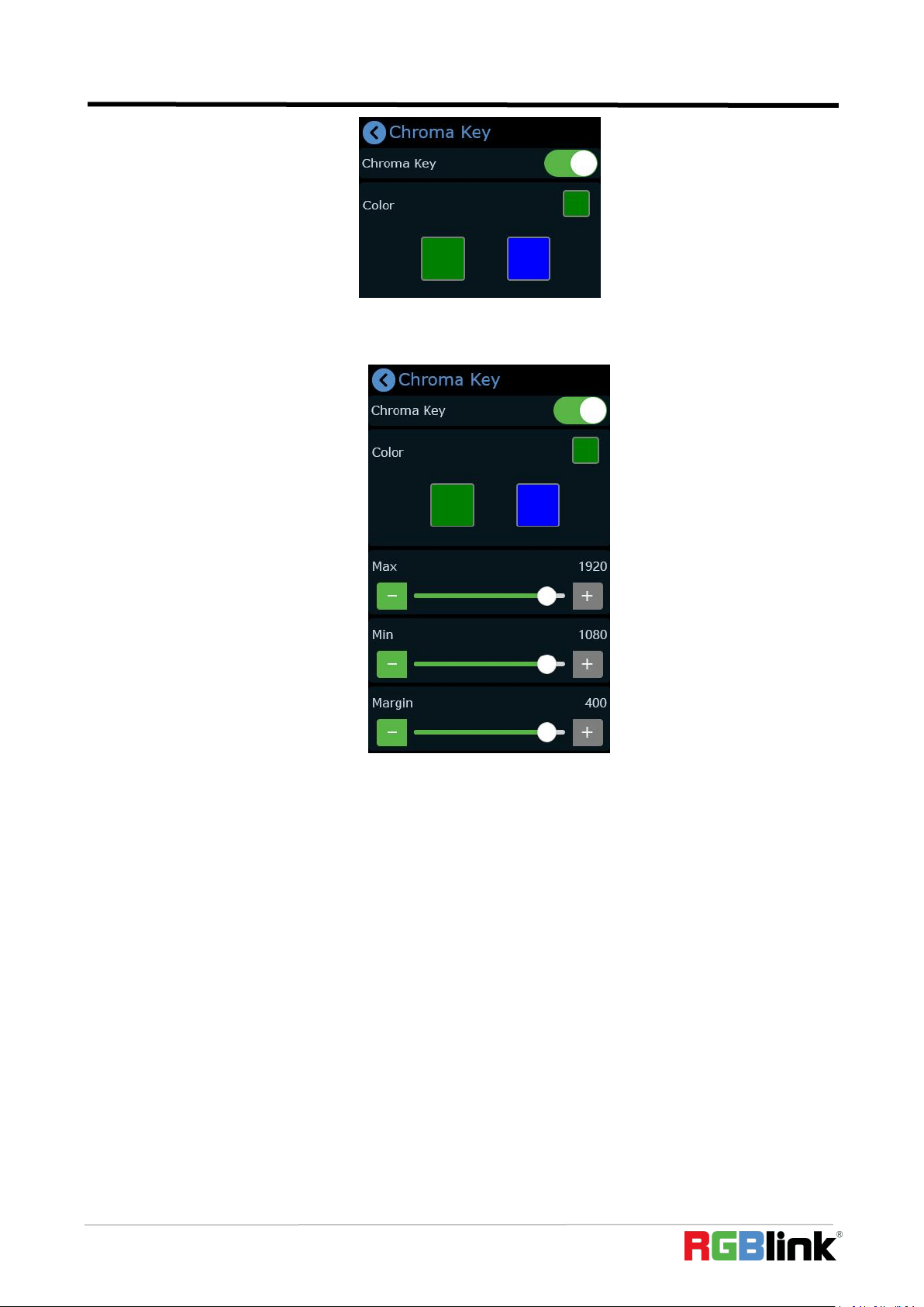
(1) Push button【M】to return to the main menu interface, find【Chroma Key】, tap this icon to
enter the setting menu.
(2) You can choose on or off to enable/disable the function. The sub-screen defaults to input 4,
and the main screen defaults to input 1, which can both be changed to other source according to
field application.
© Xiamen RGBlink Science & Technology Co., Ltd.
Ph: +86 592 5771197
25
(3) Select the background color which is default in green to be removed and make adjustments.
Similar to PIP, the size, position and cropping of the main/sub-screen can be set.
(4) After the Chroma Key is set, the parameters can be saved directly on the device. Next time
when the the device is on no matter on the dominant software XPOSE mini or the touch screen
itself, users can directly load the preset. And the layer selection stays at main screen, that is, directly
press the signal key, the main screen is switched.
(5) After loading the Chroma Key preset, you can use the joystick to switch the selection of the
main/sub-screen, push the signal source to switch between different signals, adjust the size of the
screen through the toggle, adjust the position of the screen through the joystick, and all the
re-adjusted settings will be Saved to the current View in real time.
3.8 PTZ
mini-pro can control cameras supporting VISCA protocol. Mini-pro can control the camera’s
lens moving horizontally and vertically, focus and zoom. Not only that, the mini-pro can also save
the position and zoom information of the camera, so that you can quickly retrieve it the next time
you use it.
The PTZ preset of mini-pro not only saves the parameters of the PTZ, but also includes calling
the camera, that is, when the View of the PTZ is loaded, the input is switched to the camera signal
© Xiamen RGBlink Science & Technology Co., Ltd.
Ph: +86 592 5771197
26
source at the same time.
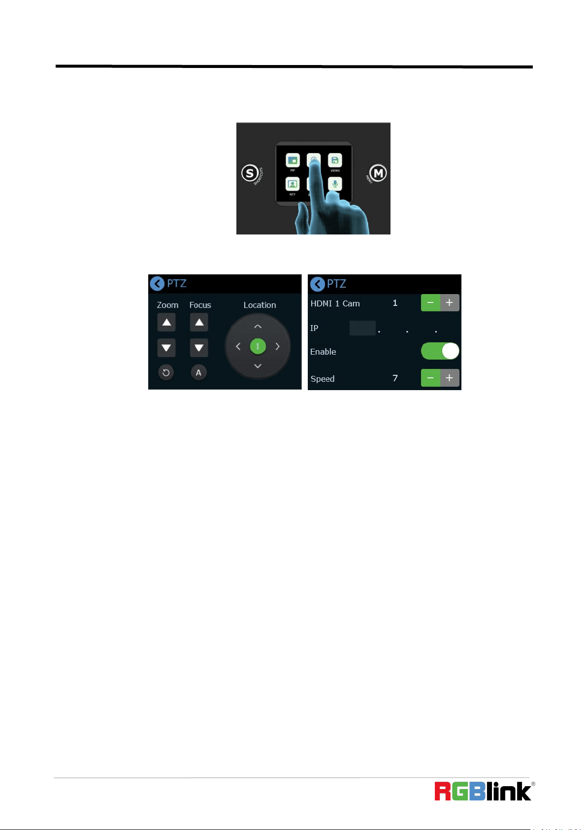
Tap the button【M】to return to the main menu, find the【PTZ】icon and tap the icon to enter
the menu.
When you want to control PTZ camera,the IP address of mini-pro and camera should be in the
same network segment.You can adjust the IP address in the menu below.
When setting PTZ, use the signal key ①②③④ to select the corresponding PTZ camera
signal to preview.
On the PTZ menu interface , when the PTZ function is enabled, the rotation angle of the PTZ
can be adjusted by the joystick, and the focal length adjusted by the toggle. Pushing signal keys can
switch the signal source between different PTZ cameras.
3.9 Record
The mini-pro supports recording streaming media content to an external SSD or USB storage
through the USB2.0 interface. The SSD storage can reach up to 2T, and the USB storage can support
up to 64G. The supported formats include exFAT. he supported SSD can reach up to 2T and USB
storage 64G and recording format is in exFAT .
Before recording, format the SSD or U-disk first.The steps of format as below:
1. Connect the SSD or U-disk to your computer
2. Open“my computer”
3. Right-click your computer and select“format”
4. Set the file system to exFAT and the size of allocation unit to 128kb
5. Select “quick format”and start
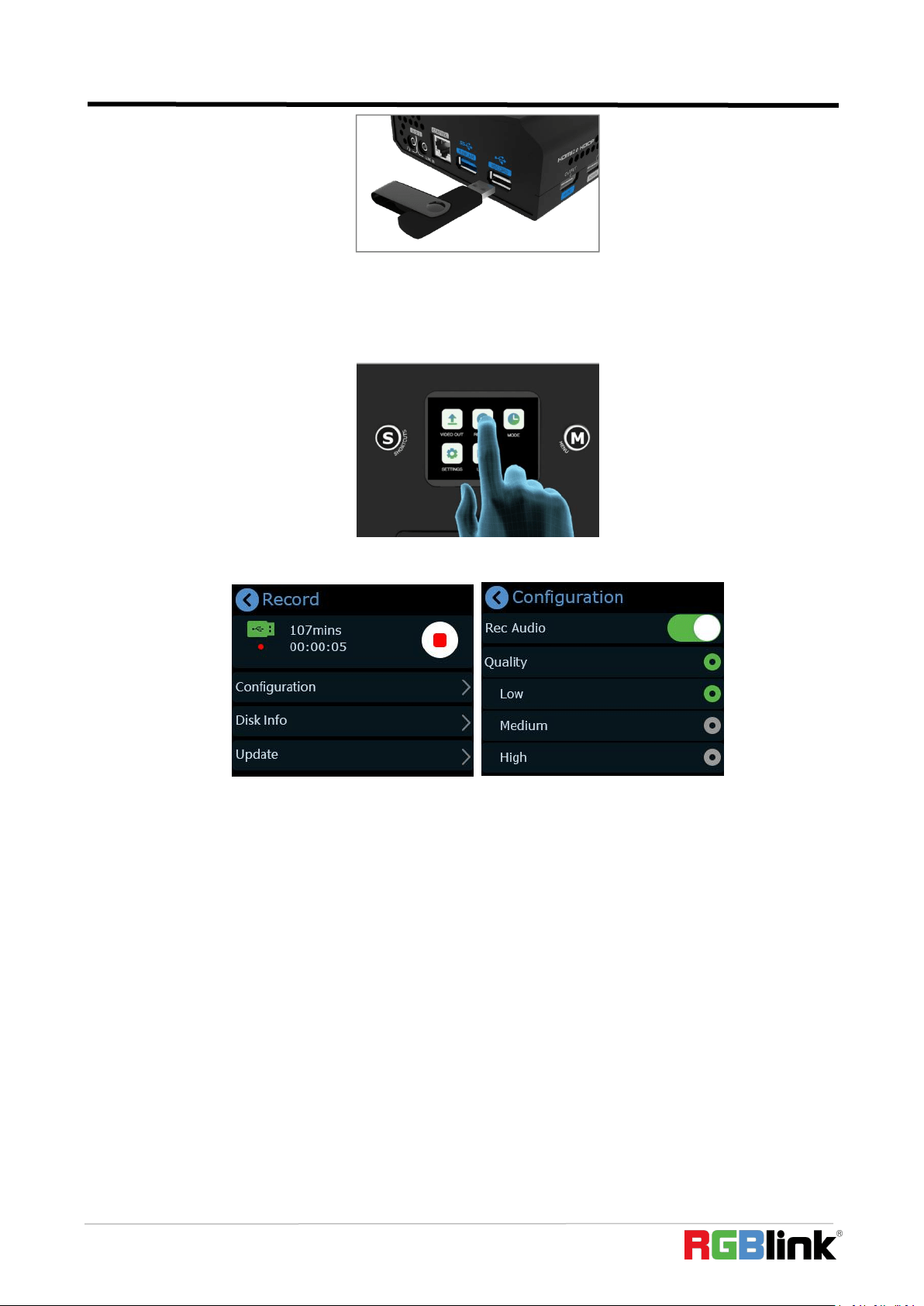
Insert the SSD or USB storage into the USB2.0 interface RECORD.
Note:If the SSD could not be recognized when inserting into mini-pro,then use a dual USB cable to power the
SSD
© Xiamen RGBlink Science & Technology Co., Ltd.
Ph: +86 592 5771197
27
mini-pro will automatically recognize the hard disk or U disk and display the relevant
information on the recording window of multi-screen PVW .
After inserting the SSD or USB storage, push button【M】to return to the main menu, and then
tap【Record】to enter the interface to switch on Record and view the status of the SSD.
Press the button to start/stop record and turn ON/OFF to record audio and set the quality.
© Xiamen RGBlink Science & Technology Co., Ltd.
Ph: +86 592 5771197
28
Chapter 4 Streaming
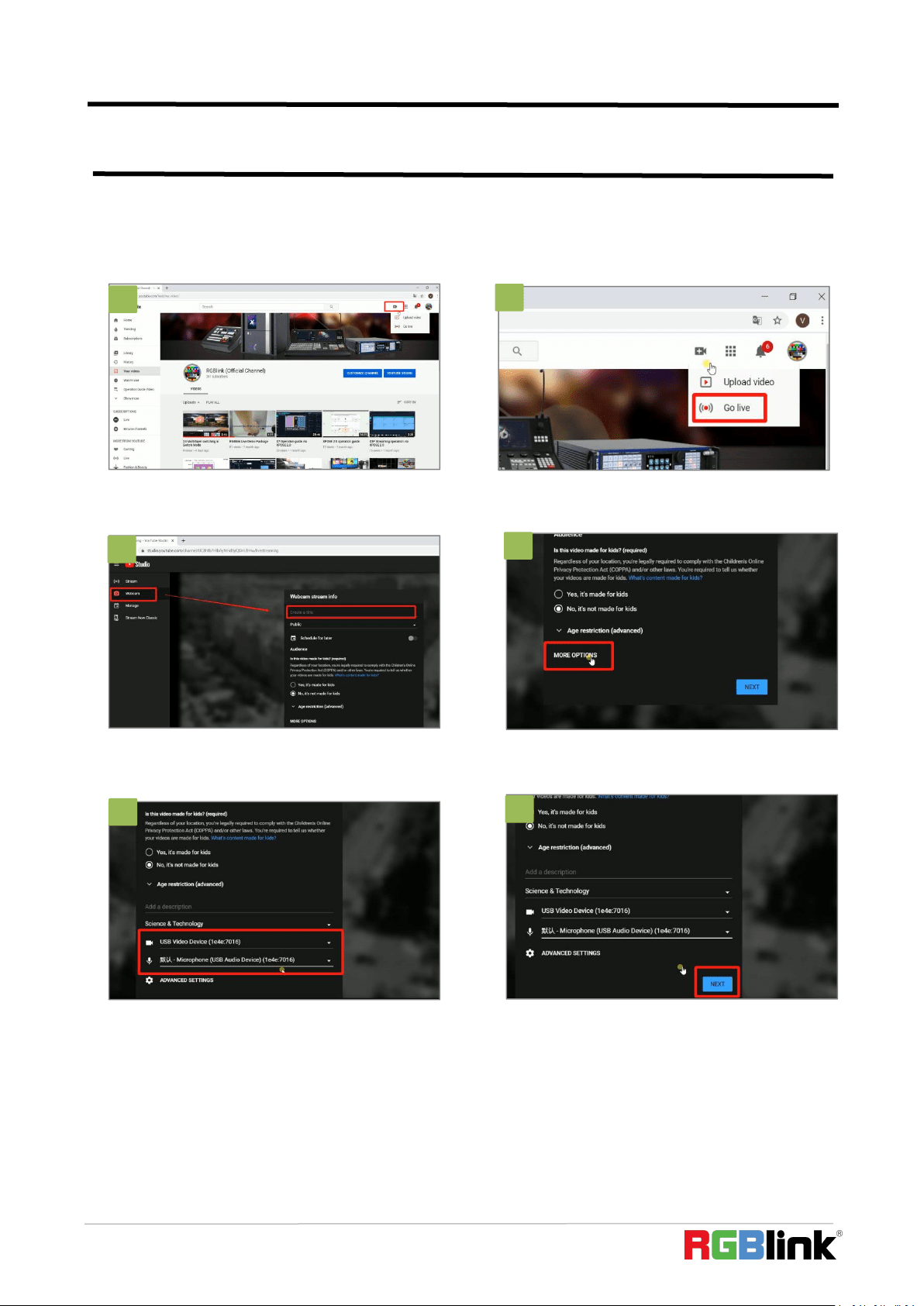
4.1 YouTube Streaming
6
6
4
4. Click “More option”.
5. Set video and audio as USB 3.0
Video/Audio device.
6. After finished all setting, click “NEXT”.
5
3
2
3. Enter Live streaming interface. And then
create a title.
1
1. Create a video or post.
2. Then click “Go live”.
6
© Xiamen RGBlink Science & Technology Co., Ltd.
Ph: +86 592 5771197
29
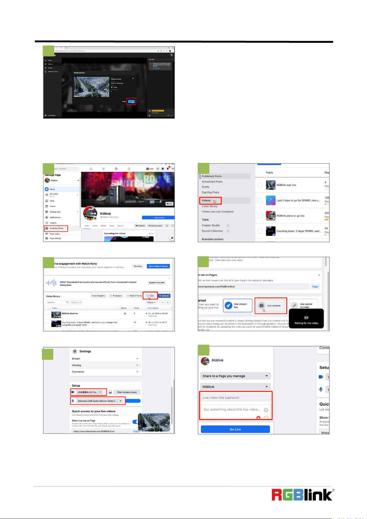
4.2 Facebook Streaming
7. Go live.
7
1. Enter “Publishing Tools”.
2. Click ”Video”
3. Click ”+Live”
4. Choose ”Use Camera”
5. Set video and audio as USB 3.0 Video/Audio
device.
6. Add a title and description.
1
2
3
4
5
6
© Xiamen RGBlink Science & Technology Co., Ltd.
Ph: +86 592 5771197
30
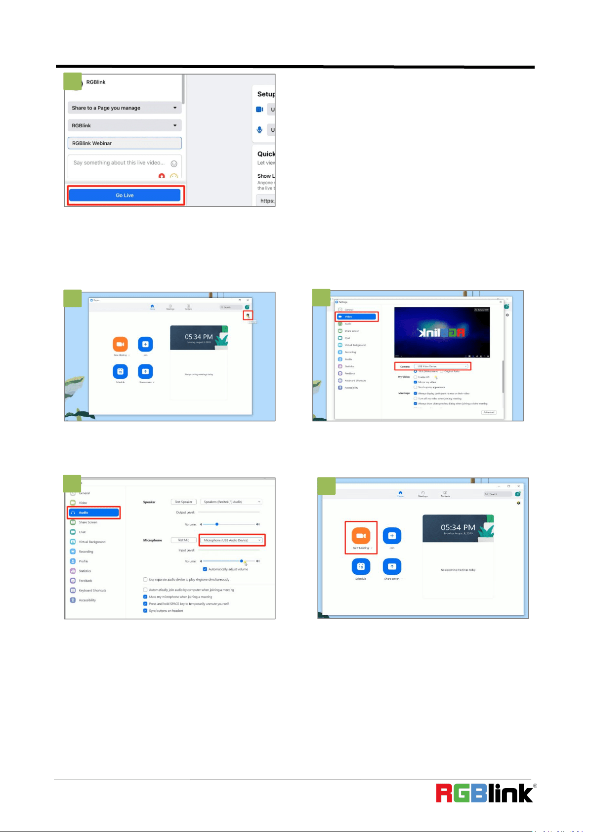
4.3 Zoom Streaming
3
2
3
4
2
7. Go Live.
7
1. Enter Zoom, click “Setting” icon.
2. Click “Video”, set Camera as “USB Video
Device”.
3. Click “Audio”, set Microphone as “USB Audio
Device”.
4. Finished all setting, Start meeting/Live.
1
3
© Xiamen RGBlink Science & Technology Co., Ltd.
Ph: +86 592 5771197
31
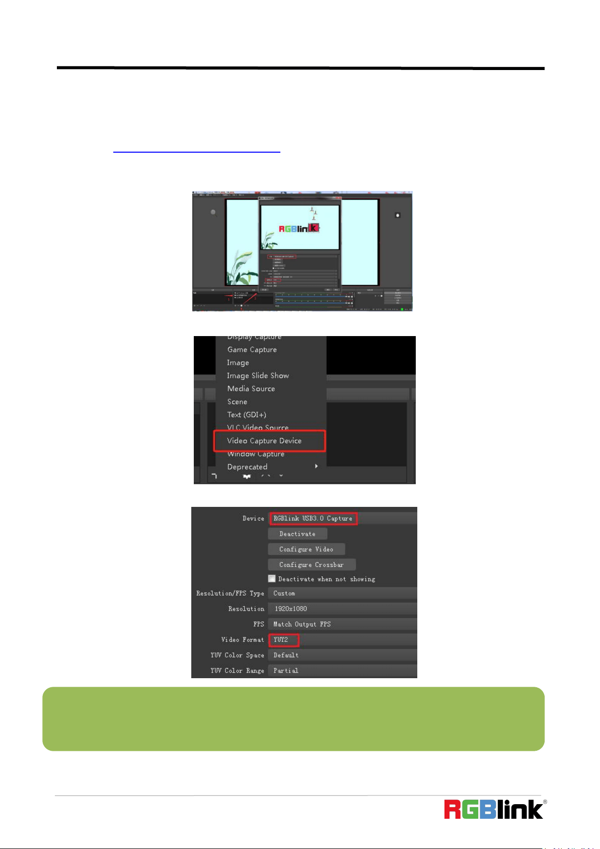
4.4 OBS Streaming
Video Capture
mini-pro is compatible with many third party steaming software, we recommend OBS, which is available to
download on https://obsproject.com/download. Download the software and update to the latest version.
1. Click”+”icon
2. choose video capture device
3. Choose :RGBlink USB 3.0 Capture and Choose Video Format YUY2
Note:If there is no video format YUY 2 after setting above, check the USB 3.0 port connection. Make sure it is
linked to USB 3.0 port on PC by USB 3.0 cable. (USB 3.0 cable or port is standard in blue while USB 2.0 is in
black).If the captured , change the video format to YUY2.
© Xiamen RGBlink Science & Technology Co., Ltd.
Ph: +86 592 5771197
32
Audio Setting
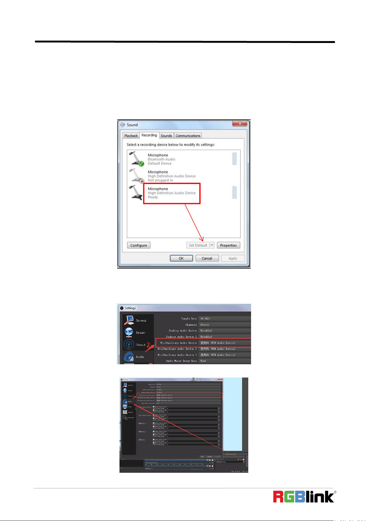
When there is no audio playing first check the video source see if the it is set in default value and then check the
audio setting on OBS.
1. Set Default for the audio source.
2. Audio setting on OBS.
Choose Audio, click Setting and choose audio device (Mic/Auxiliary Audio Device)
Synchronize Video with External Audio
When the video itself doesn’t have embedded audio and need insert external audio.Here are the steps.
1. Set the audio source: Setting→Audio→Mic/Auxiliary Audio Devices
© Xiamen RGBlink Science & Technology Co., Ltd.
Ph: +86 592 5771197
33
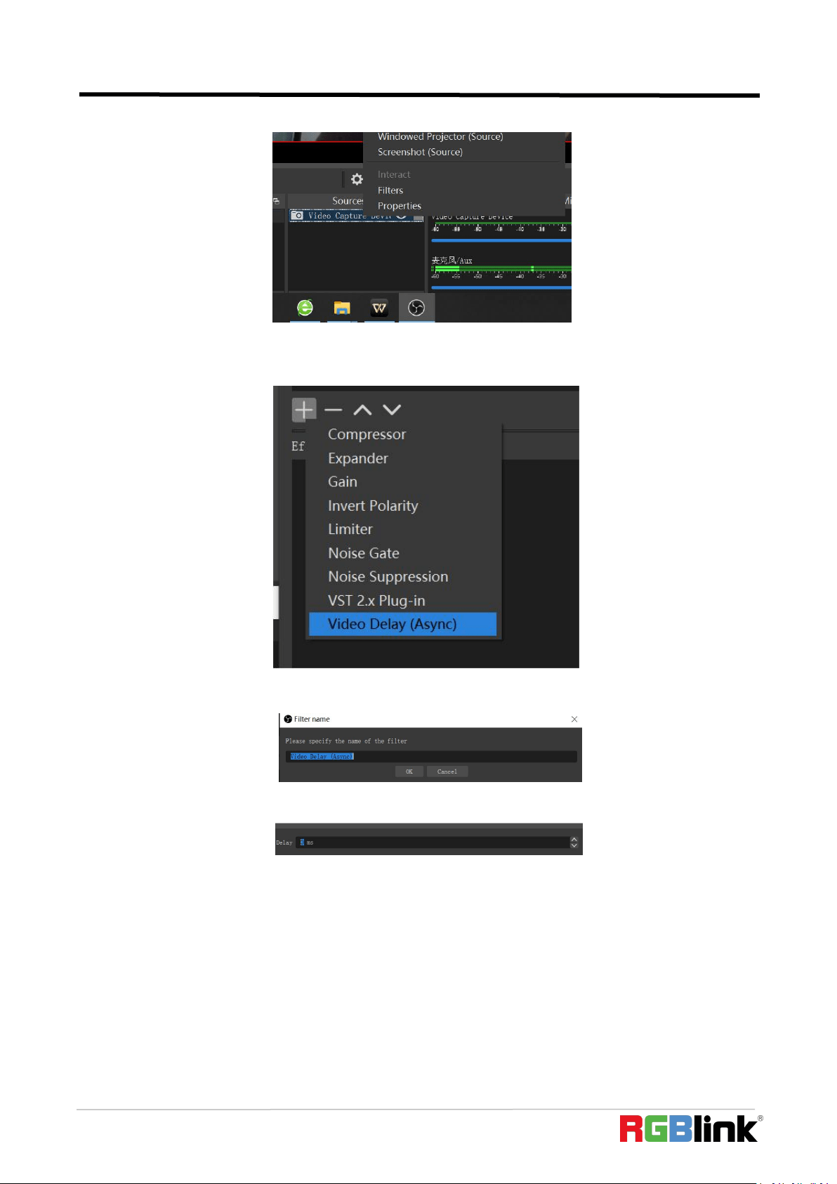
2.Right click the Video Capture Device in Source and choose Filter
3. Click “+”under Audio/Video Filters and choose Video Delay (Async)
4.You can custom the filter name in the pop-up window. Click OK to confirm the filter name.
5.Input delay value in ms, the value need to adjusted until the video and audio is synchronous.
© Xiamen RGBlink Science & Technology Co., Ltd.
Ph: +86 592 5771197
34
Streaming Setting
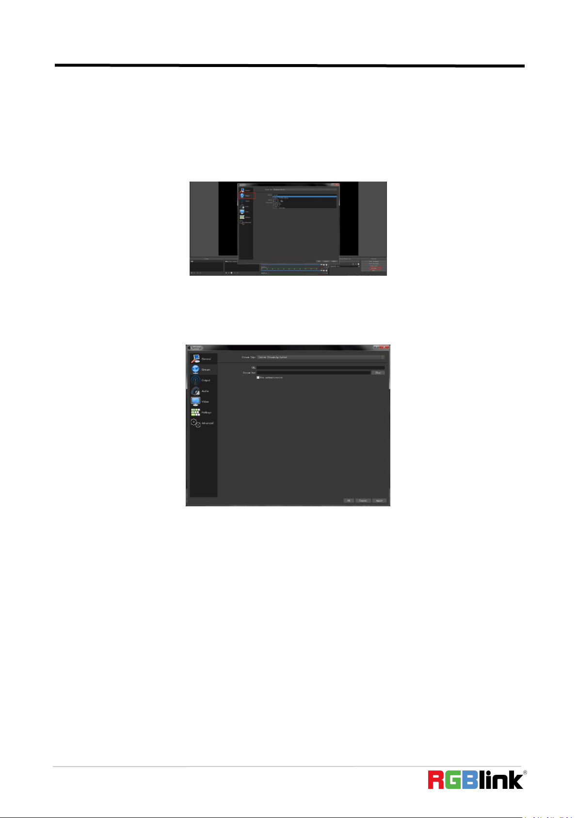
1. Find the RTMP URL and Stream Key provided by streaming broadcast website.
2. Copy URL and Stream Key
3. Back to OBS, click Setting in the lower right corner and click “Stream”. Choose Stream Type as “Streaming
Service” or “Custom Streaming Server” . If choose “Streaming Service”, there is a list of streaming service name
available in the drop down list of Service. If the streaming service is in the list, choose it from the list.
If choose Custom Service, just fill in URL and Stream Key.
4. Paste the RMTP URL to Server or URL and Stream Key to Stream Key.
5. Click “Start Streaming”.
6. Go back to live broadcast website and check the broadcasting.
© Xiamen RGBlink Science & Technology Co., Ltd.
Ph: +86 592 5771197
35
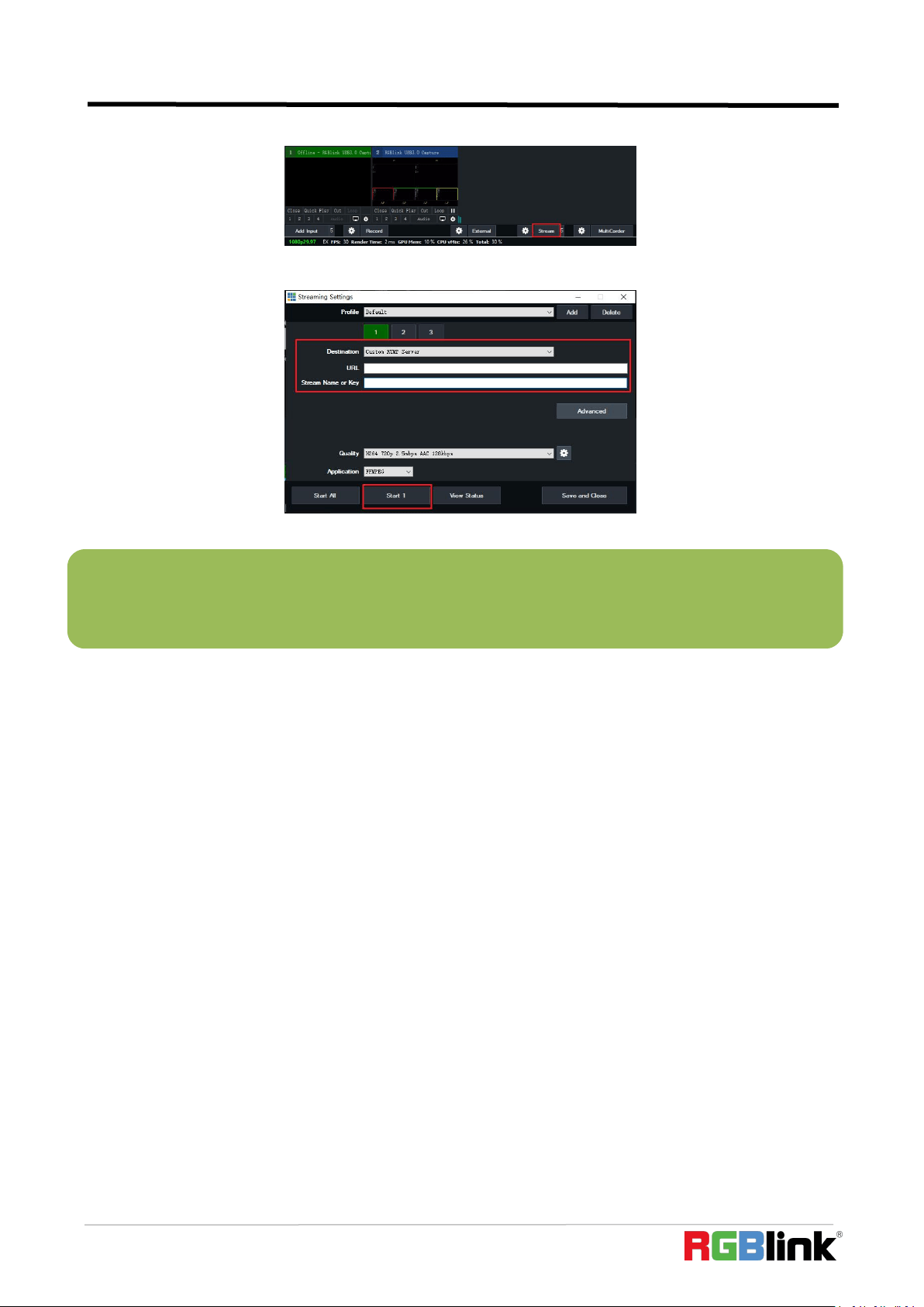
4.5 vMix Streaming
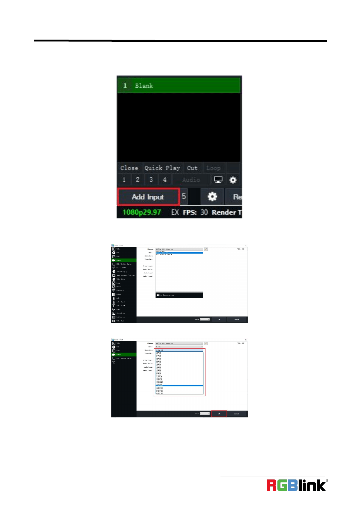
1. Click a new blank, then click the “Add Input” button.
2. Select Camera-Camera-RGBlink USB3.0 Capture.
3. Select the same resolution as the mini output. Then click “OK”.
© Xiamen RGBlink Science & Technology Co., Ltd.
Ph: +86 592 5771197
36
4. Click Stream setting button.
5. Complete the URL and Key information. Click “Start 1”,vMix will begin streaming.
Note: vMix does not support automatic recognition of the output resolution of mini-pro. Every time the output
resolution of mini-pro is modified, the picture on vMix will pause. The user needs to re-select RGBlink USB3.0
Capture and manually input the current output resolution of mini-pro.

© Xiamen RGBlink Science & Technology Co., Ltd.
Ph: +86 592 5771197
37
Chapter 5 XPOSE mini Operation
XPOSE mini is a software that allows you to control your mini-pro, RGBlink is available for all
platforms including Android, iOS, MacOS, Windows.
Minimum System Requirements for macOS
Windows:
● CPU:i5 and above
● Memory:8 GB or more
● Operating System: Windows 10 64 bit processor or above
● Graphics: Support Direct X9 128M or above (open AERO effect)
● Hard disk space: Above 16G (primary partitions, NTFS format)
● Connector: USB 3.0 or type c
● Others: do not run multiple video capture or editing software simultaneously
MAC:
●
CPU:i5 and above
● Connector: USB 3.0 or type c
● Operating System: macOS 11.0 Big Sur or later
macOS 10.15 Catalina
● Others: do not run multiple video capture or editing software simultaneously
You can either connect the mini-pro directly to your computer via the LAN port provided by the
mini-pro, or link the mini-pro to your router and the computer to the Wi-Fi emitted by your wireless
router.
5.1 Connect mini-pro and computer
Direct Link via a Network Cable
(1)Modify mini-pro’s IP Address
The mini-pro is connected to a computer via TCP/IP protocol for data transfer. Therefore, you need
to keep the mini-pro on the same IP network segment as your PC or mobile device. If the mini-pro is
connected directly to a computer, you need to change the mini-pro's IP manually to avoid IP
conflicts on the same network segment.
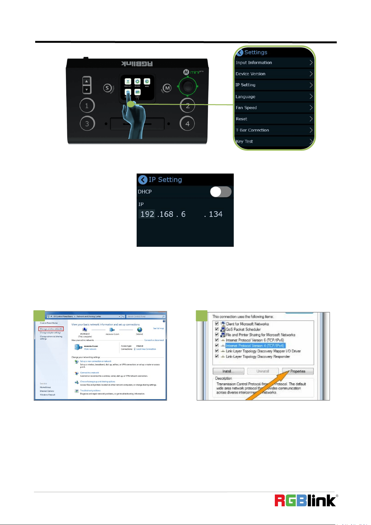
Steps to modify mini-pro’s IP address:
1. Push【M】button,enter【Settings】--【IP Setting】menu;
Note:The IP address of the mini-pro must be in the same WLAN segment as the computer or the mobile
control device you choose.
© Xiamen RGBlink Science & Technology Co., Ltd.
Ph: +86 592 5771197
38
2. Change value of IP via touch screen and toggle
(2) Change the PC’s IP Address
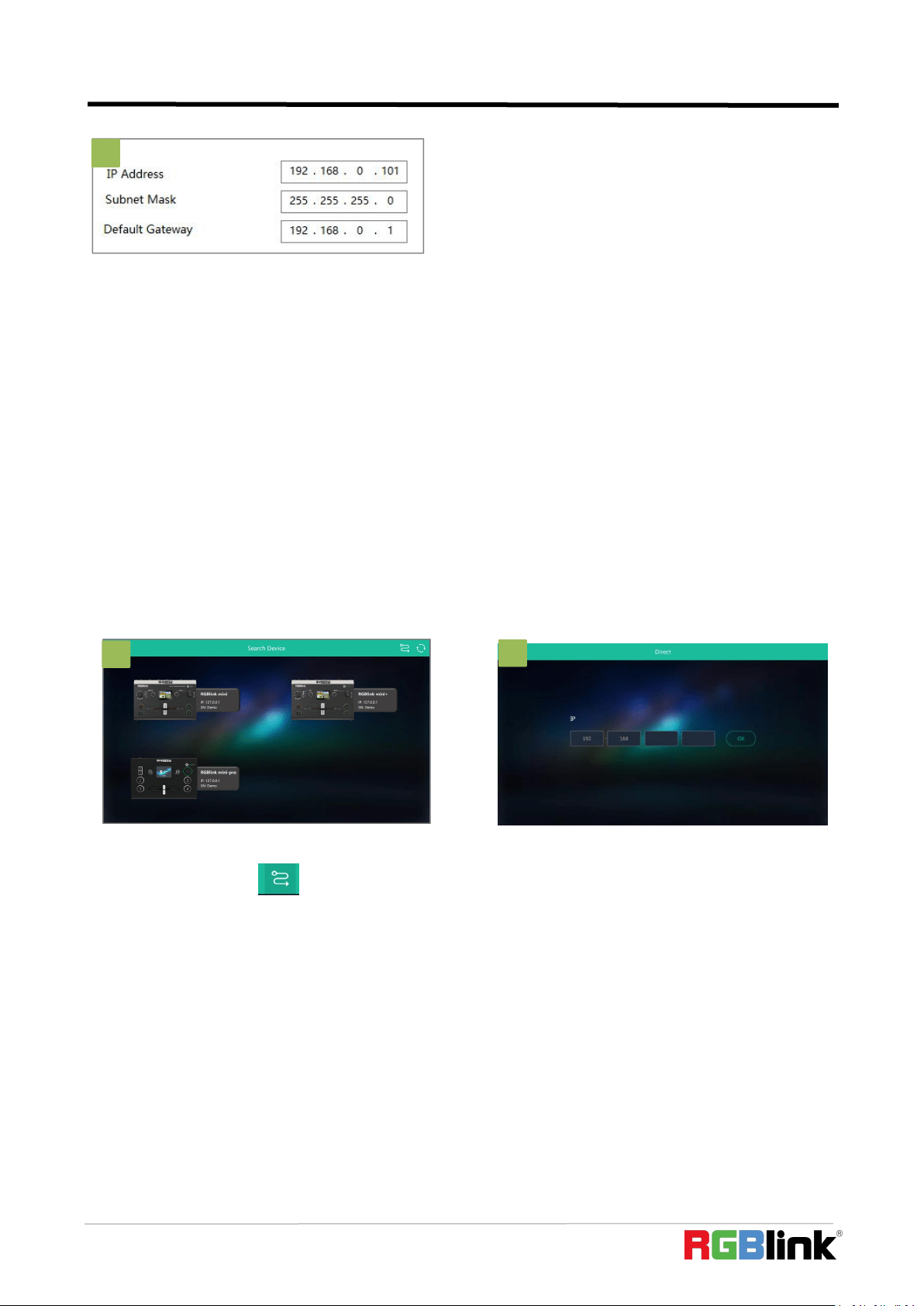
To ensure that the mini-pro and the PC can communicate smoothly, the IP address of the computer
needs to be verified.
Steps to modify the IP address of the Ethernet port (windows).
1
1. Open the Network Sharing Center;
Click on "Ethernet";
2.
2. Access to Properties may require administrator
privileges;
Under "This connection uses the following
items", find "Internet Protocol version 4
(TCP/IPv4)";
1
2
© Xiamen RGBlink Science & Technology Co., Ltd.
Ph: +86 592 5771197
39
Static Direct Connection
To ensure that XPOSE mini can connect in different classes of subnet masks, if you find that you
cannot connect to the mini series by searching, please try to use the direct connection method. The
direct connection feature was added after XPOSE mini was updated to version V1.0.0.9.
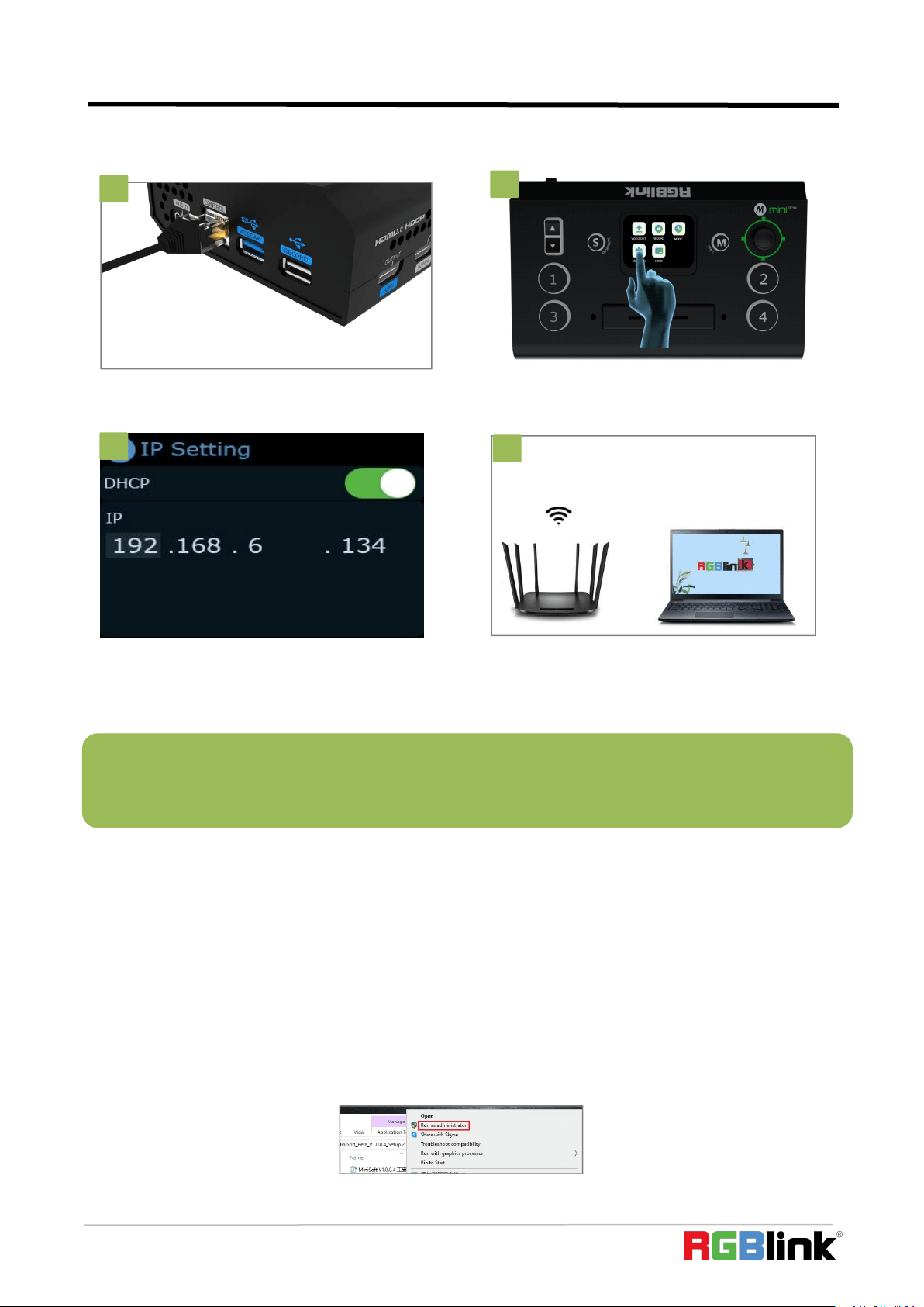
Connect Wirelessly with Your Router
The mini-pro provides wireless control, so you can control it from a greater distance when the
mini-pro is not in your immediate vicinity. A wireless router is required to use this feature. The
computer receives the WIFI signal from the wireless router you connect the mini-pro to.
1. Open XPOSE mini and click on the icon in
the upper right corner .
2. Enter the IP address of the currently
connected mini-pro.
3. Select "Use the following IP address" and
change the IP address to the same network
segment as mini-pro
eg: mini-pro's IP address is 192.168.0.99, then the
computer's IP address can be set to
192.168.0.1-255. Please make sure that the IP
addresses do not conflict.
3
1
2
© Xiamen RGBlink Science & Technology Co., Ltd.
Ph: +86 592 5771197
40
Steps of wireless connection:
5.2 Using XPOSE mini
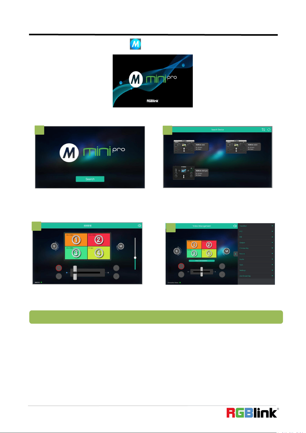
XPOSE mini simulates the mini-pro's real world appearance and the operations you can control with
XPOSE mini are very similar to those you can do with the mini-pro's hardware. XPOSE mini has put
all the functions in the "M" button. You can use this button for functions that are not possible with
the mini-pro hardware.
Install dedicated software named XPOSE to control mini-pro.
Right click the setup exe file .
Choose Run as administrator to open the exe and install the software.
2
4
1
4
4
1
3
Note:The Android and IOS versions can only connect wirelessly. Regardless of whether you are using wireless or
wired, you need to make sure that the IP addresses are on the same network segment and that they do not
conflict.
2
1
3
1. Connect the mini-pro to the router's LAN port.
2. Press the【M】button to enter【Settings】
--【IP Setting】menu.
3. Turn on the DHCP switch.
4.Computer connects to Wi-Fi from the
router,and then Open XPOSE mini search
1
4
3
© Xiamen RGBlink Science & Technology Co., Ltd.
Ph: +86 592 5771197
41
After software is installed, click the icon XPOSE and login the software
Search Device
Following sections are dedicated to the additional features of XPOSE mini.
2
3
4
1. Click Search to search mini-pro device.
2. After searching, all available mini-pro
devices in the sub-net can be found, up to 128
devices can found if there are.
3. Select the desired device by SN and IP and
enter the management interface.
4. The software interface is a simulation of
operation panel on real mini-pro device.
Note:If it is the first time for you to use XPOSE mini, we suggest you watch our User Guide video.
1
© Xiamen RGBlink Science & Technology Co., Ltd.
Ph: +86 592 5771197
42
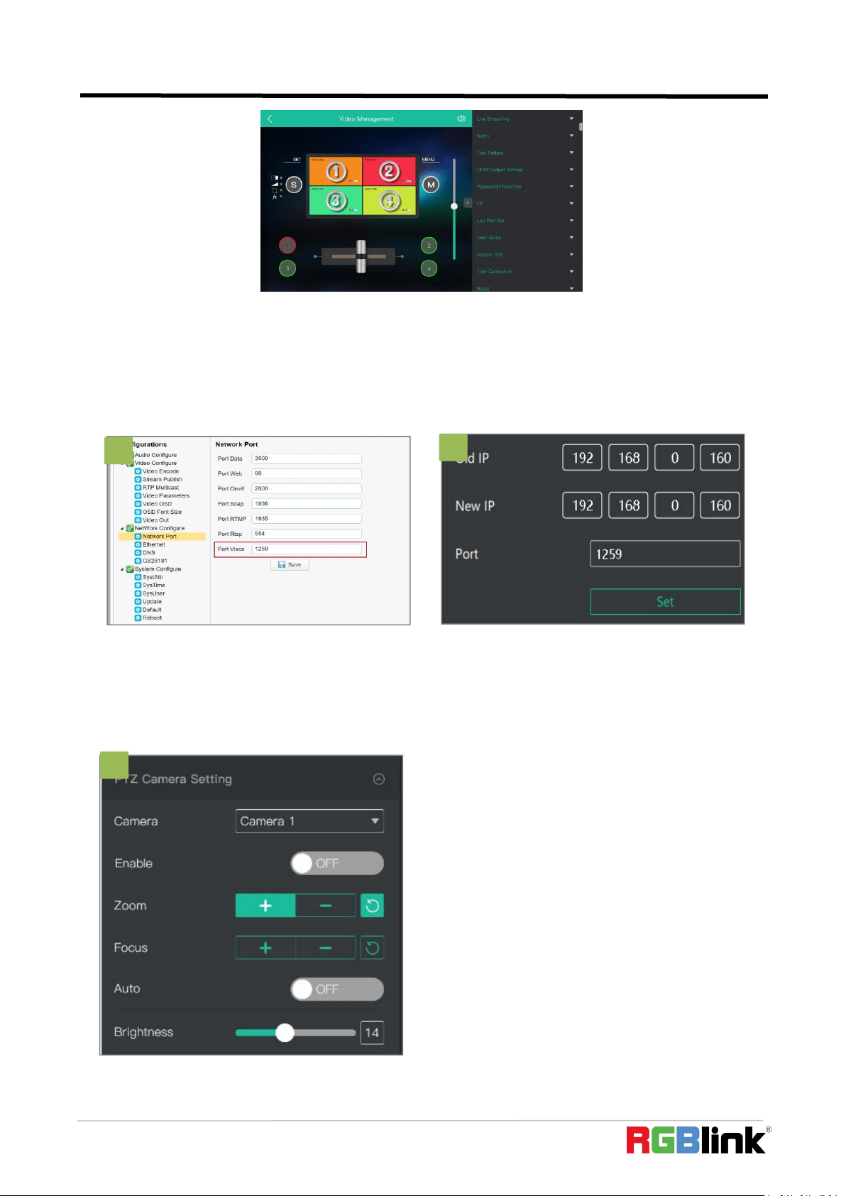
PTZ Camera Setting
When controlling the PTZ camera, the computer, mini -pro and PTZ camera should be in the same
network segment.
2
1
2
3
1
1. Set the corresponding communication port
on the PTZ camera, such as VISCA or UDP port
1259.
2. Set both old IP and new IP to the camera IP address you
want to control,the corresponding communication port to
1259 on mini-pro, configuration path: M(Menu) → FX →
PTZ Camera Setting Port on the control software of
mini-pro.
3. After IP address setting,turn on “Enable” and
you can control PTZ camera.
© Xiamen RGBlink Science & Technology Co., Ltd.
Ph: +86 592 5771197
43
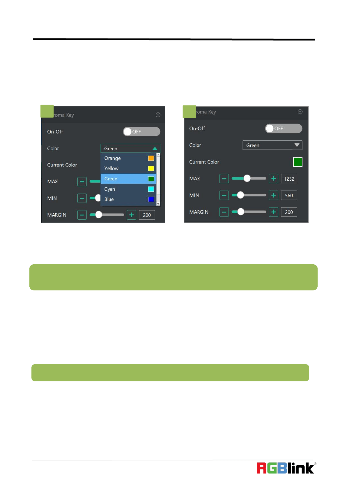
Chroma Key
mini-pro also provides chroma key of sub-screens. Sub-screen keying is possible with PIP turned
on,which helps you to combine characters with the virtual background.
Make sure to use XPOSE mini V1.0.0.9 or higher before using the latest program, and make sure to
use mini-pro V1.23 and higher.
Live Streaming
Device Capture:choose RGBlink USB3.0 Capture
H.265: When it is ON, users can watch 4 inputs streaming back on XPOSE software.
Import the related OBS application if users need to do live streaming, click Relate to confirm.
OBS: slide ON to start streaming.
1. Select the base color you want to remove,
there are 6 kinds of colors you can select:
orange, yellow, green, cyan,blue and purple.
Note:H.265 and OBS cannot work at the same time. User choose either H.265 or OBS, not both.
2. You can click in the MAX MIN MARGIN data
input box to achieve a more precise keying
effect.
Note: When using chroma key, make sure that the layer you want to edit is on the top layer, which is the B layer
in the PIP setting, otherwise you may not see the chromakey effect.
1
2
© Xiamen RGBlink Science & Technology Co., Ltd.
Ph: +86 592 5771197
44
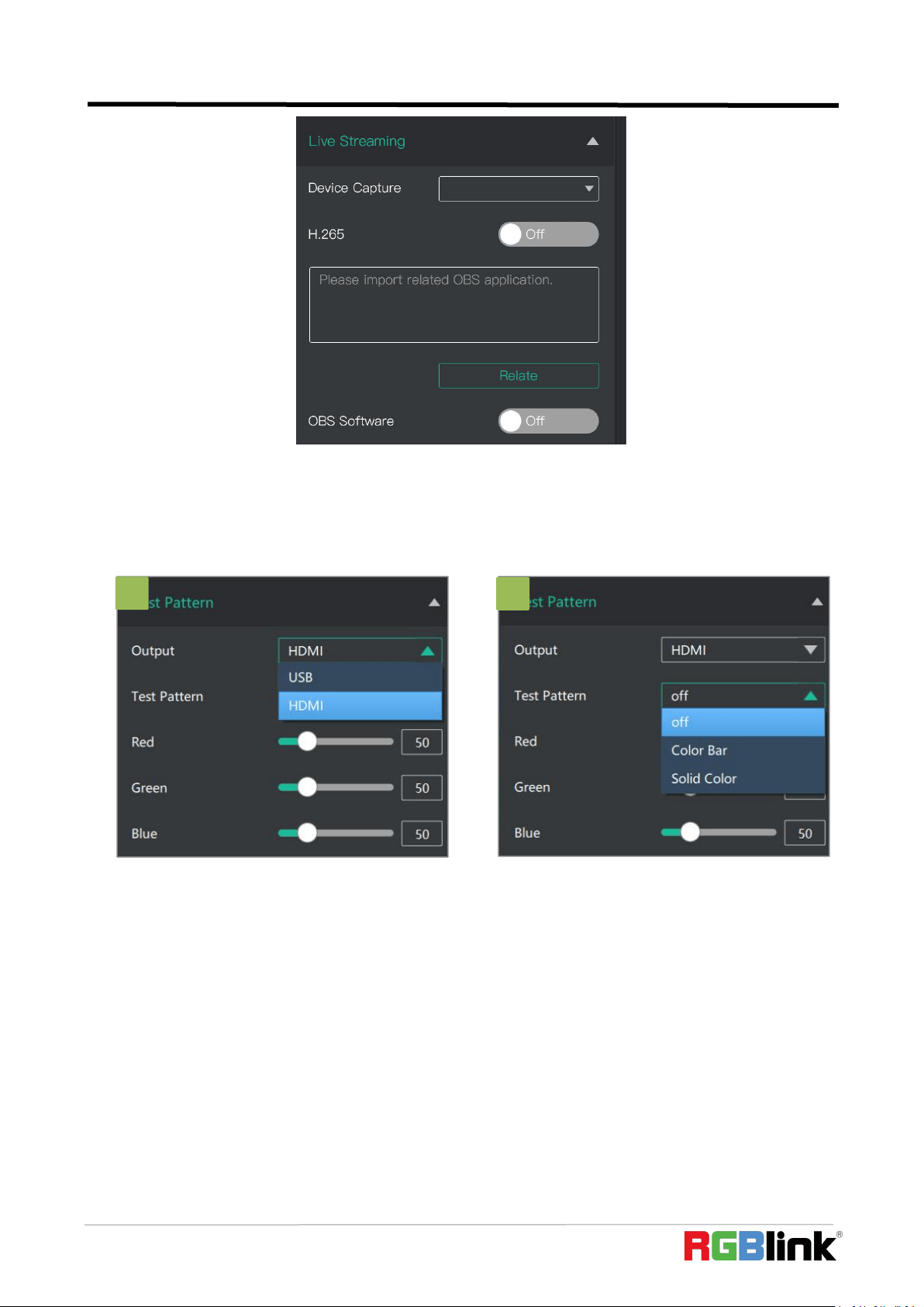
1. Select the USB/HDMI interface to be tested.
Test Pattern
To facilitate troubleshooting, XPOSE mini provides a test signal output, which can be used to
troubleshoot the USB or HDMI output interface when there is no output signal from USB or HDMI.
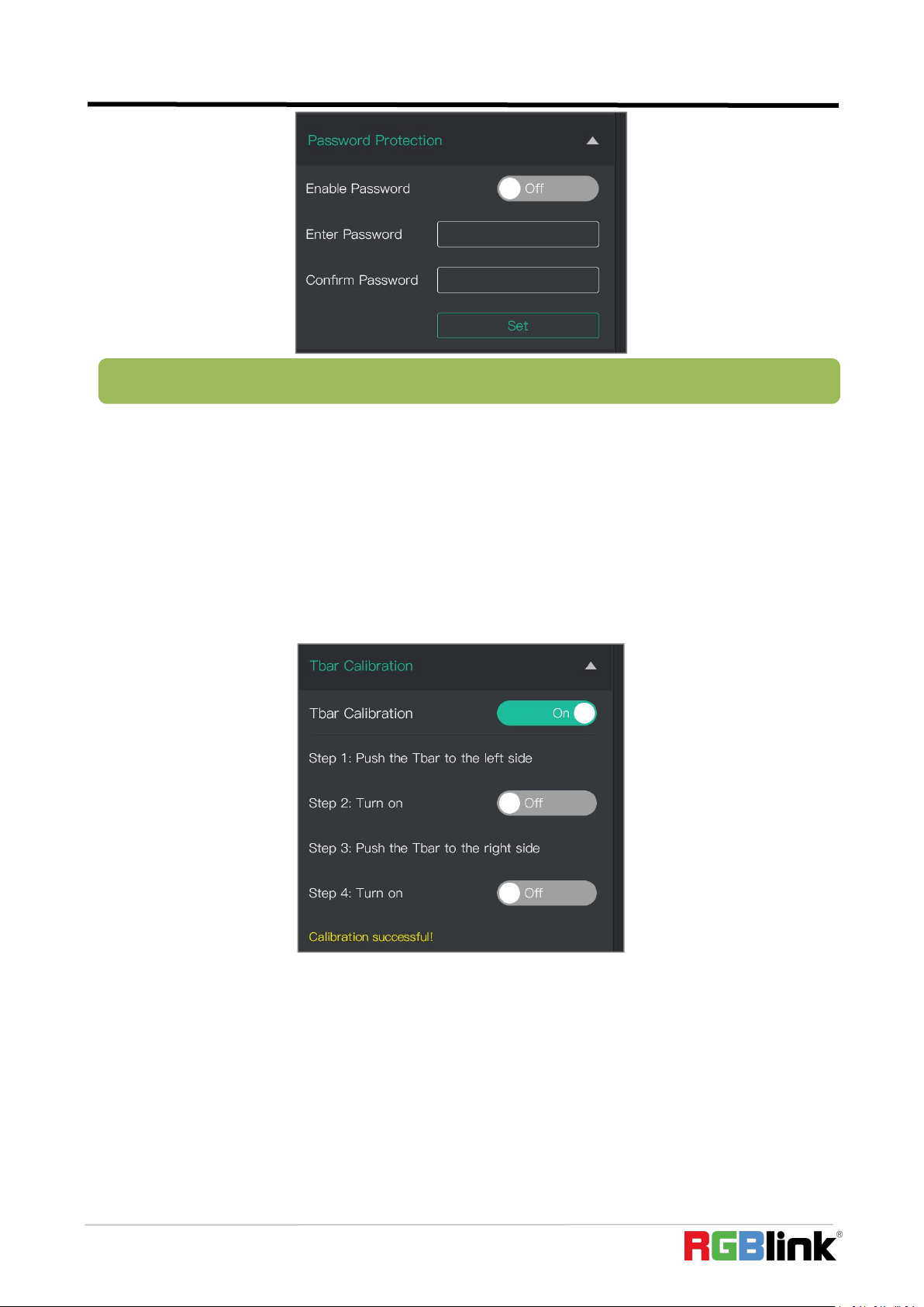
Password Protection
In order to solve the problem of control conflicts caused by different devices controlling the same
mini-pro in the same LAN, XPOSE mini provides a password protection function, as an administrator,
you can set a password for the device controlling XPOSE mini, and when you control the interface
again, you need to enter the password to control it.
2
2. Select the mode of the test pattern.
1
© Xiamen RGBlink Science & Technology Co., Ltd.
Ph: +86 592 5771197
45
T-Bar Calibration
If the T-Bar is not in the correct position, no other operation is possible. t-Bar correction is available
in XPOSE mini.
The steps are as follow:
1. Turn on the T-Bar Calibration switch.
2. Push the T-Bar to the far right on the mini-pro.
3. Turn on the "On" switch
4. Push the T-Bar to the far left on the mini-pro.
5. Turn on the "On" switch
5.3 Upgrade
1.Tools:
Firmware ZIP upgrade package
XTOOL (V1.0.1.10 or higher) -packaged in the ZIP
Computer with network connection
o Windows (minimum Win 7, Win 10 recommended)
o macOS (minimum 10.13 High Sierra)
Note: If you have forgotten your password, please restore the factory settings on the mini-pro.
© Xiamen RGBlink Science & Technology Co., Ltd.
Ph: +86 592 5771197
46
2.Upgrade
2.1 Power on the device and connect LAN ports between PC and device by Cat6 cable;
2.2xEnsure that your computer is on the same network as the mini-pro. The default IP address of
mini-pro is 192.168.0.99, in which case your computers IP address should be in the range 192.168.0.xxx (xxx cann
ot be the same as mini-pro or other device on the network) to enable connection between the mini-pro and your
computer.
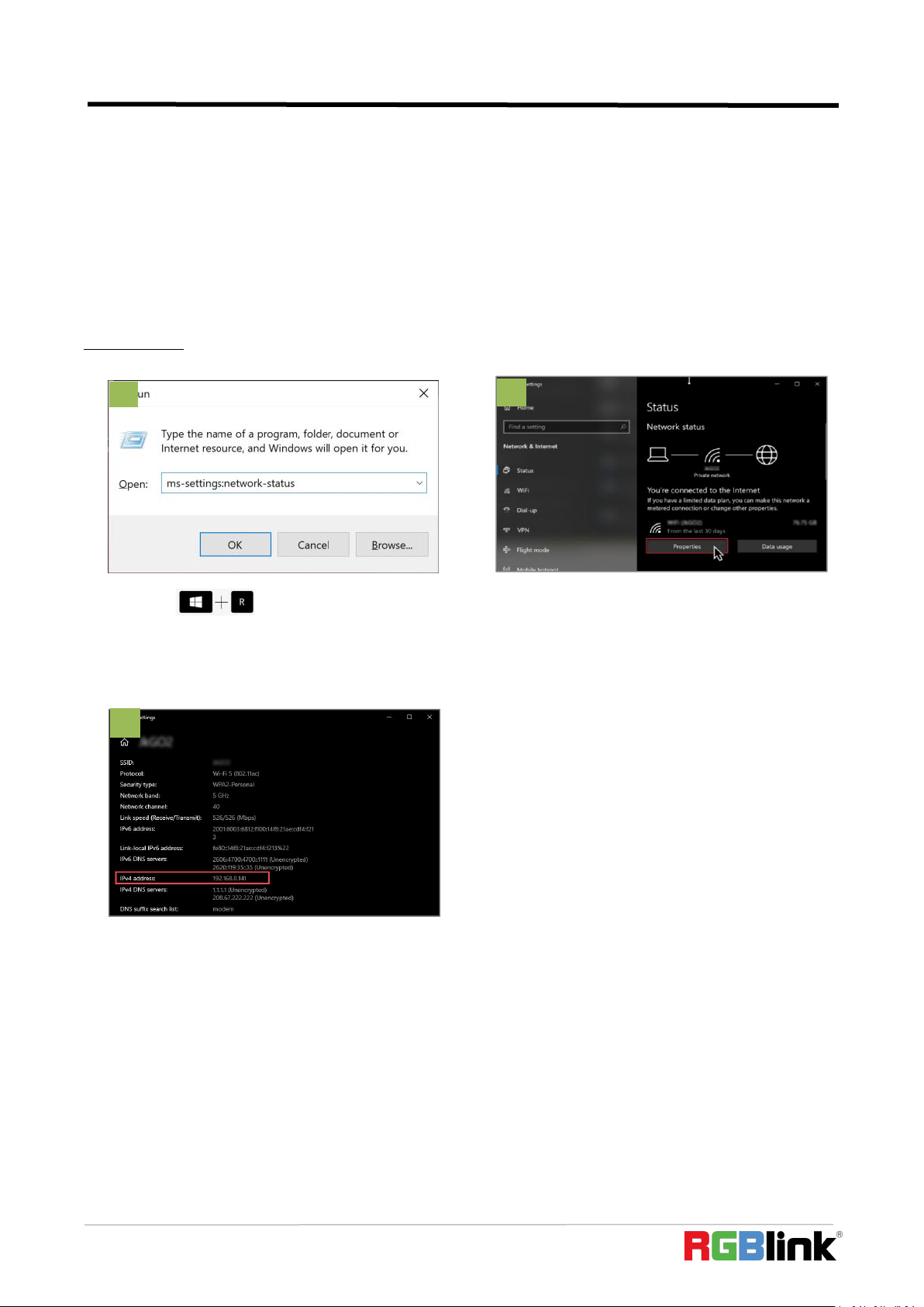
Check IP of PC:
If the IP address is not in the same section, manual change of IP address is required. Here are the steps:
Step 1. Click Start menu, click “Setting”
Step 2. Open Network and Internet > Network and Sharing Center.
Step 3. On the left pane of the new window, click Change adapter settings.
Step 4. You will be displayed with Network Connections of the PC.
Important note: Right click on “Ethernet” or “Local Area Connection” if you want to change IP of any
physical connection. And right click on “WLAN” in case you wish to change IP of any wireless connections.
1. Press keys together
to open the Command Prompt; In the dialog type:
ms-settings:network-status
2. Click on the “Properties” button
3. Scroll down to find your IP address
1
2
3
© Xiamen RGBlink Science & Technology Co., Ltd.
Ph: +86 592 5771197
47
Step 5. Choose Properties after right clicking on the network name.
Step 6. Select the Internet Protocol Version 4 (TCP/IPv4), then click Properties.
Step 7. Obtain an IP Address automatically should be selected by default, but please choose the Use the
Following IP Address.
Step 8. Now put your desired IP Address according to your wish its correct format. Change Subnet mask
and default gateway if you want to.
Install XTOOL App
Step 1. Extract the Firmware ZIP package into a folder
Step 2. Navigate to the /Upgrade Tool/XTOOL folder
Step 3. Right mouse-click the XTOOL Soft Setup and Run as Administrator [Windows]
Step 3. Follow the Setup Wizard to install all the components. There will be multiple Dialog windows pop-up for
installing the necessary components (refer XTOOL Installation Guide)
If the XTOOL app has been installed previously, use the Modify option to complete the setup.
XTOOL is a universal updater application for RGBlink products, as such has a number of features in support of
the full range of RGBlink devices that are not utilized for mini-pro updates in this guide.
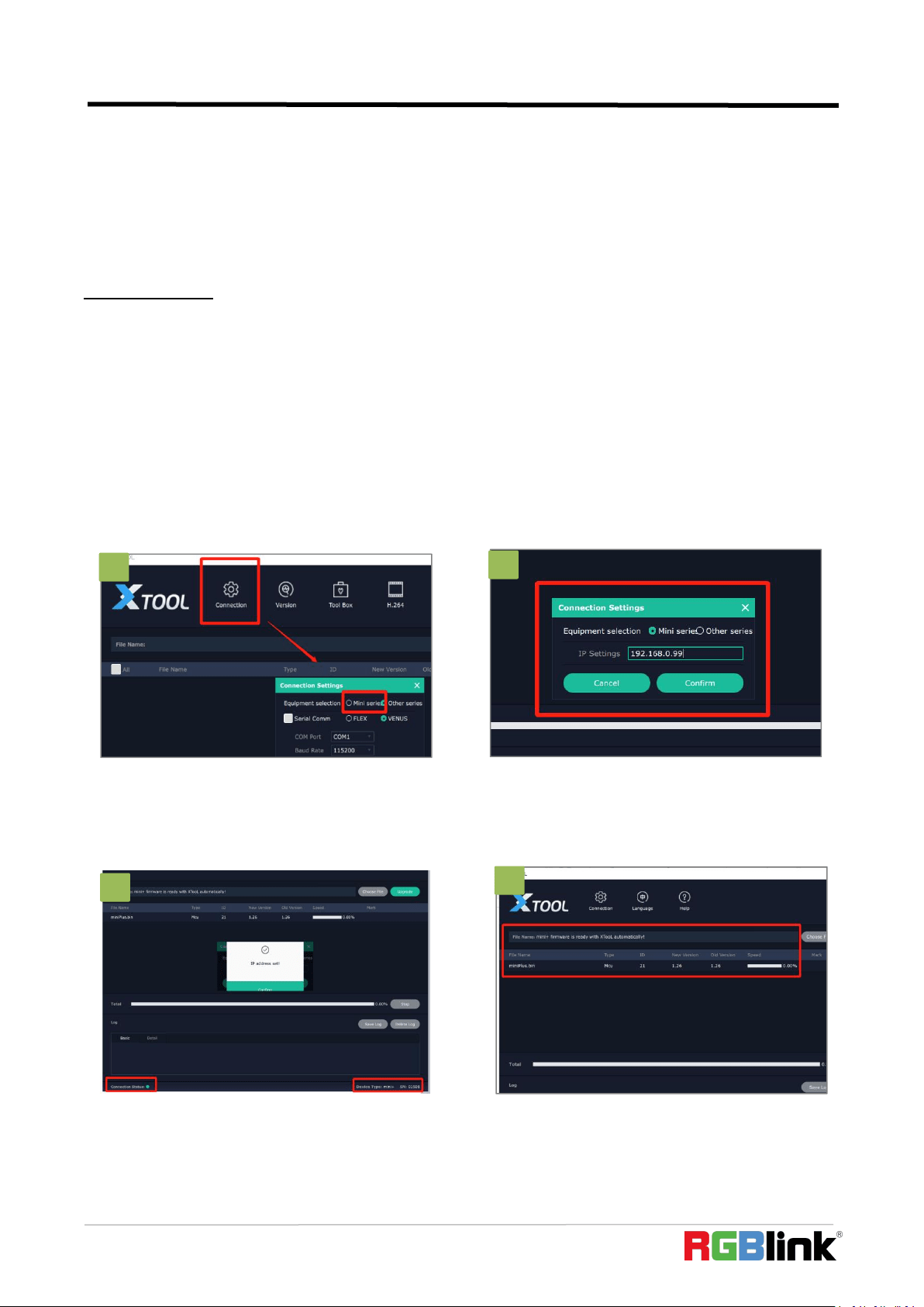
1. Upgrade
Open the XTOOL app with Run as Administrator [Windows]
1. Click”Connection”and select “mini series”
2. Fill in the IP Address of the mini-pro(as
example above, default mini-pro IP is
192.168.0.99),and click “Confirm”.
3. Review Connection Status at bottom left, to
confirm indicator light is green and there is
device information showing at bottom right.
4. The firmware package will be ready with
XTOOL automatically.
1
2
3
4
2
4
3
© Xiamen RGBlink Science & Technology Co., Ltd.
Ph: +86 592 5771197
48
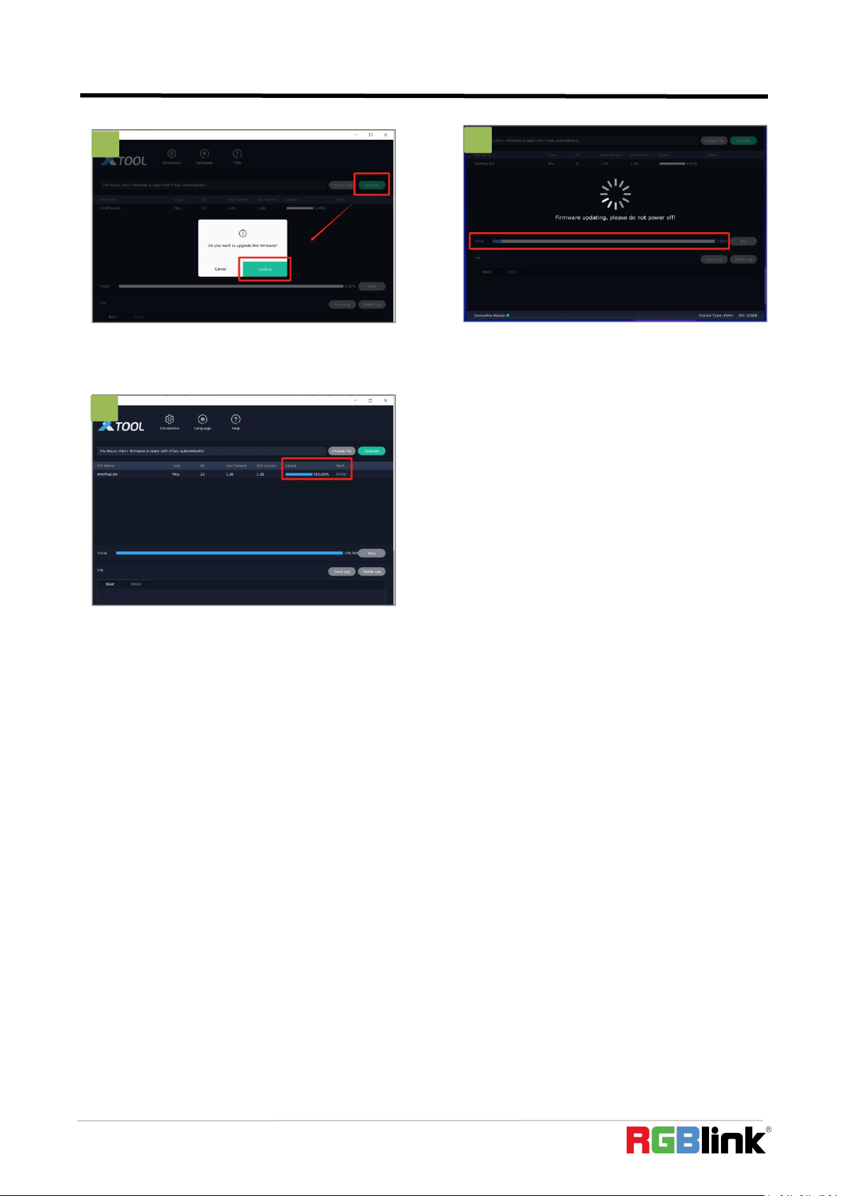
5. Click”Upgrade”and click “Confirm”in the
pop-up windows.
6. Firmware is upgrading and you can monitor the
progress.Please do not power off while upgrading.
7. mini-pro is now upgraded and ready to use.
5
6
7
6
5
7
7

© Xiamen RGBlink Science & Technology Co., Ltd.
Ph: +86 592 5771197
49
Chapter 6 Ordering Codes
6.1 Product Code
230-0003-02-0 mini-pro
© Xiamen RGBlink Science & Technology Co., Ltd.
Ph: +86 592 5771197
50
Chapter 7 Appendix
7.1 Specification
Connectors
Input
HDMI 4K
4×HDMI-A
Output
HDMI 2K
1×HDMI-A
Streaming
1×USB Type-A
Recording
1×USB Type-A
Audio
In
2×3.5mm Stereo Jack
Out
1×3.5mm Stereo Jack
Communication
LAN
1×RJ45
Power
1×PD Type-C
Performance
Input Resolutions
HDMI
SMPTE
VESA
720p@50/60 |1080i@50 | 1080p@24/30/50/60 |2160p@60
1024×768@60 | 1280×720@60 | 1280×768@60 | 1280×800@60 |
1280×1024@60 | 1360×768@60 | 1366×768@60 | 1440×900@60 |
1600×1200@60 | 1680×1050@60 | 1920×1080@60 |
1920×1200@60 | 3840×2160@60 | 4096×2160@60
Output Resolutions
HDMI
SMPTE
VESA
USB |H.265
SMPTE
720p@50/60 | 1080p@24/25/30/50/60
1024×768@60 | 1280×720@50/60 | 1280×768@60 |
1280×1024@60 | 1360×768@60 |1920×1080@24/25/30/50/60
720p@60 | 1080p@60
Supported Standards
HDMI
2.0
USB
3.0
H.265
ITU-T H.265/ ISO/IEC 23008-2
Supported Protocol
PTZ
VISCA
Color Space
RGB
Video Sampling
4:4:4 YUV
Latency
﹤
4 frames
Line In Delay
Up to 8 frames
Power
Input Voltage
PD 12V/1.5A(via plug pack supplied)
Contact Power
13.2W
Max Power
20W

© Xiamen RGBlink Science & Technology Co., Ltd.
Ph: +86 592 5771197
51
7.2 FAQ
1. When there is a problem with mini-pro.
A:We recommend you to upgrade to the latest version of firmware first, then reset and restart the device.
2. If there is a power supply problem with the mini-pro.
A:Please try to change the power adapter (support 20W).
3. mini-pro upgrade notes.
A
:
Please disable the other adapters(except mini-pro LAN adapter) on Network and Internet, turn off the DHCP on
setting of mini-pro, after upgrading successfully, remember to reset and restart the device.
4. mini-pro cannot control PTZ.
A:Please make sure that the IP address of mini-pro and PTZ are in the same network segment. For example, the IP
address of PTZ is 192.168.5.163. Please also set the IP address of mini-pro to 192.168.5.X ( (2~254) except163
Outside), confirm on mini XPOSE whether the Visca port number in the PTZ settings is the corresponding port
number, for example, the Visca port number of the PTZ of RGBlink is 1259.
5. mini-pro USB2.0 RECORD cannot recognize U disk.
A
:
Please format the U disk (exFAT, FAT32).
6. mini-pro USB3.0 WEBCAM cannot be recognized/recognized without picture(black picture).
A
:
Please confirm whether the computer configuration meets the following conditions, if not, please select one of
the following methods 6.1)-6.5) for testing:
Windows:
CPU:i5 and above
Memory:8 GB or more
Operating System: Windows 10 64 bit processor or above
Graphics: Support Direct X9 128M or above (open AERO effect)
Hard disk space: Above 16G (primary partitions, NTFS format)
Connector: USB 3.0 or type c
Environment
Temperature
0
℃
~60
℃
Humidity
10%~85%
Physical
Weight
Net
0.42kg
Package
1.20kg
Dimension
Net
180mm×118.3mm×58.4mm
Package
255mm×145mm×85mm

© Xiamen RGBlink Science & Technology Co., Ltd.
Ph: +86 592 5771197
52
Others: do not run multiple video capture or editing software simultaneously
MAC:
CPU:i5 and above
Connector: USB 3.0 or type c
Operating System: macOS 11.0 Big Sur or later macOS 10.15 Catalina
Others: do not run multiple video capture or editing software simultaneously
6.1)Or use typeC to USB3.0 hub to connect the computer and mini-pro
6.2)Or use USB software->ProcessControl_1.0.0.2 to improve performance of computer(in the attachment)
6.3)Lower the output resolution
6.4)Unplug and plug the USB3.0 cable and re-enter the streaming software.
6.5)Change the USB2.0 cable to do streaming (note that the picture quality is lower than the USB3.0 cable, and
the USB2.0 cable is not recommended to use the PVW output)
7. Does mini-pro support HDCP?
A
:
The HDMI input supports the HDCP protocol, HDMI input 1 port supports HDCP2.X, the other input ports
support HDCP1.X, and the output does not support HDCP protocol encryption
8. mini-pro HDMI input what kind of YUV.
A
:
mini-pro supports 4:4:4
,
not supports 4:2:0.
9. When mini-pro input is i format signal will be half-screened or cut with the P format signal, the height of the
P format will be cut.
A:At present, the latest program can automatically determine the i/P signal source and automatically adjust the
cropping value.
10. Can mini-pro be controlled by mobile phone?
A : At present, the Android version has been uploaded on the official website, the IOS version is still being
uploaded, and the version in the APP Store does not control the mini-pro.
11. When the mini-pro switch is turned on and power on, plug in the USB cable to USB2.0 RECORD port, and
the LCD screen will sometimes flicker.
A
:
Hardware repair has been done, if this situation occurs, please try to turn off the switch, unplug the power, and
power on again.
12. Can mini-pro recording be paused, If you stop recording and then start recording again, will it be saved in a
new file?
A:Currently there is no pause function. Restarting recording will save a new file.
13. Can mini-pro control PTZ of Pelco protocol?

© Xiamen RGBlink Science & Technology Co., Ltd.
Ph: +86 592 5771197
53
A
:
Currently, the PTZ controlling this protocol is not supported, mini-pro supports to control Visca protocol PTZ.
7.3 Terms & Definitions
●RCA:
Connector used primarily in consumer AV equipment for both audio and video. The RCA connector
was developed by the Radio Corporation of America.
●
BNC:
Stands for Bayonet Neill-Concelman. A cable connector used extensively in television (named for its inventors). A
cylindrical bayonet connector that operates with a twist-locking motion .
●CVBS: C
VBS or Composite video, is an analog video signal without audio. Most commonly CVBS is used for
transmission of standard definition signals. In consumer applications the connector is typically RCA type, while in
professional applications the connector is BNC type.
●YPbPr: Used to describe the colour space for progressive-scan. Otherwise known ascomponent video.
●VGA: Video Graphics Array. VGA is an analog signal typically used on earlier computers. The signal is non-interlaced in
modes 1, 2, and 3 and interlaced when using in mode.
●DVI:
Digital Visual Interface. The digital video connectivity standard that was developed by DDWG (Digital Display
Work Group). This connection standard offers two different connectors: one with 24 pins that handles digital
video signals only, and one with 29 pins that handles both digital and analog video.
●SDI: Serial Digital Interface. Standard definition video is carried on this 270 Mbps data transfer rate. Video pixels are
characterized with a 10-bit depth and 4:2:2 color quantization. Ancillary data is included on this interface and typically
includes audio or other metadata. Up to sixteen audio channels can be transmitted. Audio is organised into blocks of 4
stereo pairs. Connector is BNC.
●HD-SDI: High-definition serial digital interface (HD-SDI), is standardized in SMPTE 292M this provides a nominal data
rate of 1.485 Gbit/s.
●3G-SDI: Standardized in SMPTE 424M, consists of a single 2.970 Gbit/s serial link that allows replacing dual link
HD-SDI.
●6G-SDI: Standardized in SMPTE ST-2081 released in 2015, 6Gbit/s bitrate and able to support 2160p@30.
●12G-SDI: Standardized in SMPTE ST-2082 released in 2015, 12Gbit/s bitrate and able to support 2160p@60.
●U-SDI: Technology for transmitting large-volume 8K signals over a single cable. a signal interface called the ultra high
definition signal/data interface (U-SDI) for transmitting 4K and 8K signals using a single optical cable. The interface was
standardized as the SMPTE ST 2036-4.
●HDMI: H
igh Definition Multimedia Interface: An interface used for the transmission of uncompressed high

© Xiamen RGBlink Science & Technology Co., Ltd.
Ph: +86 592 5771197
54
definition video, up to 8 channels of audio, and control signals, over a single cable.
●HDMI 1.3: Released on June 22 2006, and increased the maximum TMDS clock to 340 MHz (10.2 Gbit/s). Support
resolution 1920 × 1080 at 120 Hz or 2560 × 1440 at 60 Hz). It added support for 10 bpc, 12 bpc, and 16 bpc color depth
(30, 36, and 48 bit/px), called deep color.
●HDMI 1.4: Released on June 5, 2009, added support for 4096 × 2160 at 24 Hz, 3840 × 2160 at 24, 25, and 30 Hz, and
1920 × 1080 at 120 Hz. Compared to HDMI 1.3, 3 more features added which are HDMI Ethernet Channel (HEC) , audio
return channel (ARC),3D Over HDMI, a new Micro HDMI Connector, an expanded set of color spaces.
●HDMI 2.0: Released on September 4, 2013 increases the maximum bandwidth to 18.0 Gbit/s. Other features of HDMI
2.0 include up to 32 audio channels, up to 1536 kHz audio sample frequency, the HE-AAC and DRA audio standards,
improved 3D capability, and additional CEC functions.
●HDMI 2.0a: Was released on April 8, 2015, and added support for High Dynamic Range (HDR) video with static
metadata.
●HDMI 2.0b: Was released March, 2016, support for HDR Video transport and extends the static metadata signaling to
include Hybrid Log-Gamma (HLG).
●HDMI 2.1: Released on November 28, 2017. It adds support for higher resolutions and higher refresh rates, Dynamic
HDR including 4K 120 Hz and 8K 120 Hz.
●DisplayPort: A VESA standard interface primarily for video, but also for audio, USB and other data. DisplayPort (orDP)
is backwards compatible with HDMI, DVI and VGA.
●DP 1.1: Was ratified on 2 April 2007, and version 1.1a was ratified on 11 January 2008. DisplayPort 1.1 allow a
maximum bandwidth of 10.8 Gbit/s (8.64 Gbit/s data rate) over a standard 4-lane main link, enough to support
1920x1080@60Hz
●DP 1.2: Introduced on 7 January 2010, effective bandwidth to 17.28 Gbit/s support increased resolutions, higher
refresh rates, and greater color depth, maximum resolution 3840 × 2160@60Hz
●DP 1.4: Publish on 1 Mar, 2016.overall transmission bandwidth 32.4 Gbit/s ,DisplayPort 1.4 adds support for Display
Stream Compression 1.2 (DSC), DSC is a "visually lossless" encoding technique with up to a 3:1 compression ratio. Using
DSC with HBR3 transmission rates, DisplayPort 1.4 can support 8K UHD (7680 × 4320) at 60 Hz or 4K UHD (3840 × 2160)
at 120 Hz with 30 bit/px RGB color and HDR. 4K at 60 Hz 30 bit/px RGB/HDR can be achieved without the need for DSC.
●Multi-mode Fiber: Fibers that support many propagation paths or transverse modes are called multi-mode fibers,
generally have a wider core diameter and are used for short-distance communication links and for applications where
high power must be transmitted.
●Single-mode Fiber: Fiber that support a single mode are called single-mode fibers. Single-mode fibers are used for
most communication links longer than 1,000 meters (3,300 ft).
●SFP: Small form-factor pluggable , is a compact, hot-pluggable network interface module used for
both telecommunication and data communications applications.
© Xiamen RGBlink Science & Technology Co., Ltd.
Ph: +86 592 5771197
55
●Optical Fiber Connector: Terminates the end of an optical fiber, and enables quicker connection and disconnection
than splicing. The connectors mechanically couple and align the cores of fibers so light can pass. 4 most common types
of optical fiber connectors are SC, FC, LC,ST.
●SC: (Subscriber Connector), also known as the square connector was also created by the Japanese company – Nippon
Telegraph and Telephone. SC is a push-pull coupling type of connector and has a 2.5mm diameter. Nowadays, it is used
mostly in single mode fiber optic patch cords, analog, GBIC, and CATV. SC is one of the most popular options, as its
simplicity in design comes along with great durability and affordable prices.
●LC
:
(Lucent Connector) is a small factor connector (uses only a 1.25mm ferrule diameter) that has a snap coupling
mechanism. Because of its small dimensions, it is the perfect fit for high-density connections, XFP, SFP, and SFP+
transceivers.
●FC: (Ferrule Connector) is a screw type connector with a 2.5mm ferrule. FC is a round shaped threaded fiber optic
connector,mostly used on Datacom, telecom, measurement equipment, single-mode laser.
●ST: (Straight Tip) was invented by AT&T and uses a bayonet mount along with a long spring-loaded ferrule to support
the fiber.
●USB: Universal Serial Bus is a standard that was developed in the mid-1990s that defines cables, connectors and
communication protocols. This technology is designed to allow a connection, communication and power supply for
peripheral devices and computers.
●USB 1.1: Full–Bandwidth USB, specification was the first release to be widely adopted by the consumer market. This
specification allowed for a maximum bandwidth of 12Mbps.
●USB 2.0: or Hi–Speed USB, specification made many improvements over USB 1.1. The main improvement was an
increase in bandwidth to a maximum of 480Mbps.
● USB 3.2: Super Speed USB with 3 varieties of 3.2 Gen 1(original name USB 3.0), 3.2Gen 2(original name USB 3.1), 3.2
Gen 2x2 (original name USB 3.2) with speed up to 5Gbps,10Gbps,20Gbps respectively.
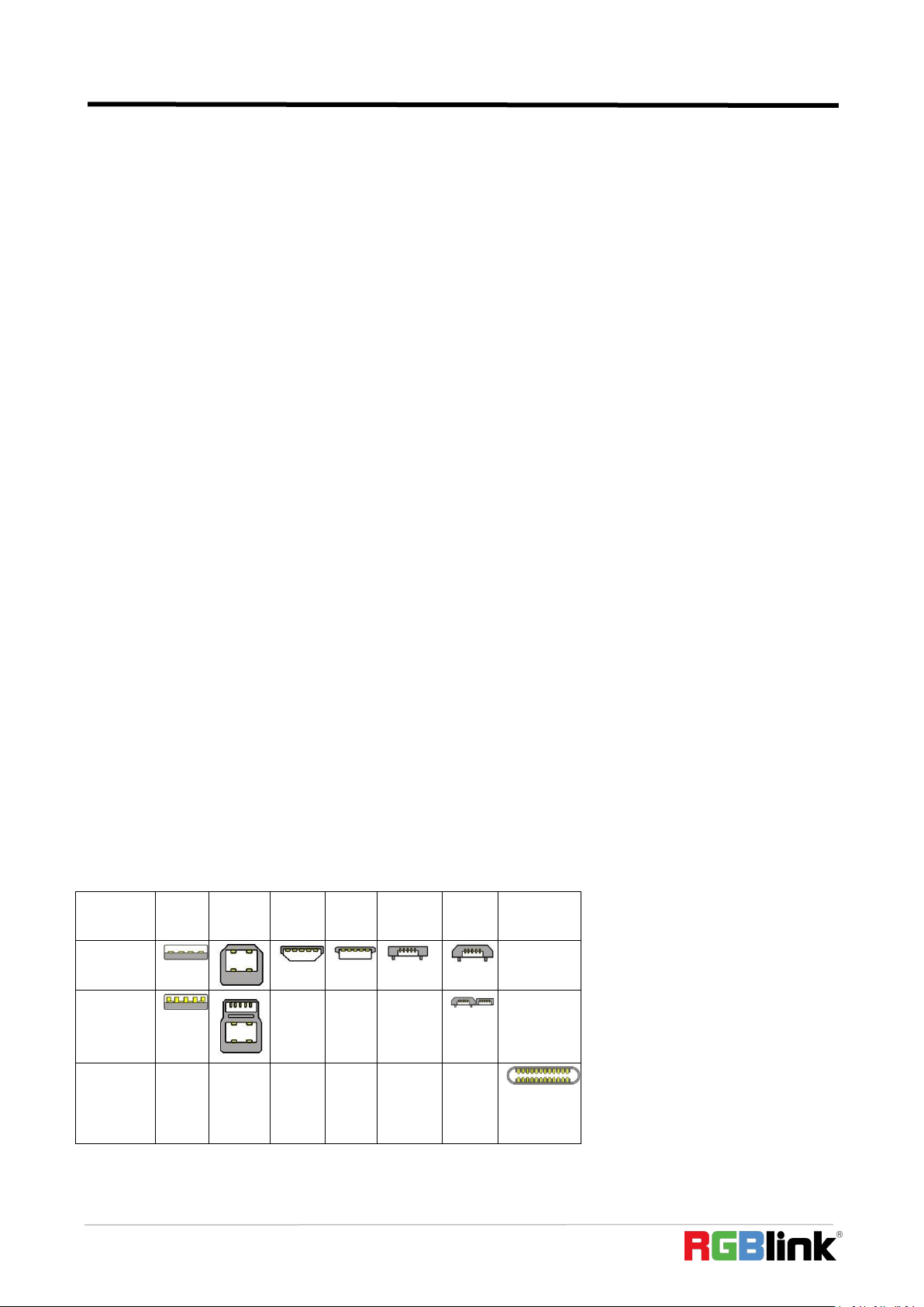
USB version and connectors figure:
Type
A
Type B
Mini
A
Mini
B
Micro-
A
Micro
-B
Type C
USB 2.0
USB 3.0
USB
3.1&3.2

© Xiamen RGBlink Science & Technology Co., Ltd.
Ph: +86 592 5771197
56
●
NTSC:
The colour video standard used in North America and some other parts of the world created by the
NationalTelevisionStandards Committee in the 1950s. NTSC utilizes an interlaced video signals.
●
PAL:
Phase Alternate Line. A television standard in which the phase of the colour carrier is alternated from line to line. It
takes four full images (8 fields) for the colour-to-horizontalimages (8 fields) for the colour-to-horizontal phase
relationship to return to the reference point. This alternation helps cancel out phase errors. For this reason, the hue
control is not needed on a PAL TV set. PAL, is widely used in needed on a PAL TV set. PAL, is widely used in Western
Europe, Australia, Africa, the Middle East, and Micronesia. PAL uses 625-line, 50-field (25 fps) composite colour
transmission system.
●
SMPTE:
Society of Motion image and Television Engineers. A global organization, based in the United States, that sets
standards for baseband visual communications. This includes film as well as video and television standards.
●
VESA:
Video Electronics Standards Association. An organization facilitating computer graphics through standards.
●
HDCP:
High-bandwidth Digital Content Protection (HDCP) was developed by Intel Corporation an is in wide use for
protection of video during transmission betweendevices.
●
HDBaseT:
A video standard for the transmission of uncompressed video (HDMI signals) and related features using Cat
5e/Cat6 cabling infrastructure.
●ST2110: A SMPTE developed standard, ST2110 describes how to send digital video over and IP networks. Video is
transmitteduncompressed with audio and other data in a separate streams.
SMPTE2110 is intended principally for broadcast
production and distribution facilities where quality and flexibility are
more important.
●
SDVoE:
Software Defined Video over Ethernet (SDVoE) is a method for transmission, distribution and management AV
signals using a TCP/IP Ethernet infrastructure for transport with low latency. SDVoE is commonly used in integration
applications.
●
Dante AV:
The Dante protocol was developed for and widely adopted in audio systems for
the transmission of
uncompressed digital
audio on IP based networks. The more recent Dante AV specification includes support for digital
video.
●
NDI:
Network Device interface (NDI) is a software standard developed by NewTek to enable
video-compatible
products to communicate,
deliver, and receive broadcast quality video in a high quality, low latency manner that is
frame-accurate and suitable for switching in
a live production environment over TCP (UDP) Ethernet based networks.
NDI is
commonly found in broadcastapplications.
●RTMP: Real-Time Messaging Protocol (RTMP) was initially a proprietary protocol developed by Macromedia (now
Adobe) for streaming audio, video and data over the Internet, between a Flash player and a server.
●RTSP:
The Real Time Streaming Protocol (RTSP) is
a network control protocol designed for use in entertainment and
communications systems to control streaming media servers. The protocol is used for establishing and controlling media

© Xiamen RGBlink Science & Technology Co., Ltd.
Ph: +86 592 5771197
57
sessions between end points.
●MPEG: Moving Picture Experts Group is a working group formed from ISO and IEC developing standards that allow
audio/video digital compression and Transmission.
●H.264: Also known as AVC (Advanced Video Coding) or MPEG-4i is a common video
compression standard. H.264 was
standard
ized by the ITU-T Video Coding Experts Group (VCEG) together with the ISO/IEC JTC1 Moving Picture Experts
Group (MPEG).
●H.265: Also known asHEVC (High Efficiency Video Coding )H.265 is the successor to the widely used H.264/AVC
digital video coding standard.Developedundertheauspices of ITU,resolutions upto8192x4320may be compressed.
●
API:
An Application Programming Interface (API) provides a predefined function which allows accesscapabilities
andfeaturesorroutinesviaa
software or hardware, without accessing source
code or understanding the details of inner
workingmechanism. AnAPI call mayexecute a
function and/or provide datafeedback/report.
●
DMX512:
The communication standard developed by USITT forentertainment anddigital lighting systems.The wide
adoption of the Digital Multiplex (DMX) protocol has seen the protocol used for a wide
range of other devices including
video controllers.
DMX512 is delivered over cable of 2 twisted pairs with 5pin XLR cables for connection.
●ArtNet: An ethernet protocol based on TCP/IP protocol stack, mainly used in entertainment/events applications. Built
on the DMX512 data format, ArtNet enables multiple “universes” of DMX512 to be transmitted using ethernet
networks for transport.
●
MIDI:
MIDI is the abbreviation of Musical Instrument Digital Interface. As the name indicates the protocol was
developed for
communication between electronical musical
instruments and latterly computers. MIDI instructions are
triggers or commands sent over twisted pair cables, typically using 5pin DIN connectors.
●OSC:
The principle of Open Sound Control
(OSC) protocol is for networking sound
synthesizers, computers, and
multimedia
devices for musical performance or show control. As with XML and JSON, the OSC protocol allows sharing
data. OSC is transported via UDP packets between devices connected on an Ethernet.
●Brightness:
Usually refers to the amount or intensity
of video light produced on a screen without regard to colour.
Sometimes called black level.
●
Contrast
Ratio:
The ratio of the high light output level divided by the low light output level. In theory, the
contrast ratio of the television system should be at least 100:1, if not 300:1. In reality, there are several limitations.
Well-controlled viewing conditions should yield a practical contrast ratio of 30:1 to 50:1.
●
Colour
Temperature: The colour quality, expressed in degrees Kelvin (K), of a light source. The higher the
colour
temperature, the bluer the light. The lower the temperature, the redder the light. Benchmark colour temperature
for the A/V industryinclude5000°K,6500°K,and9000°K.
●
Saturation:
Chroma, Chroma gain. The intensity of the colour, or the extent to which a given colour in any image is free

© Xiamen RGBlink Science & Technology Co., Ltd.
Ph: +86 592 5771197
58
from white. The less white in a colour, the truer the colour or the greater its saturation. Saturation is the amount of
pigment in a colour, and not the intensity.
●
Gamma:
The light output of a CRT is not linear with respect to the voltage input. The difference between what
you should have and what is actually output is known as gamma.
●Frame: In interlaced video, a frame is one complete image.A video frame is made up of two fields, or two sets of
interlaced lines. In a film, a frame is one still image of a series that makes up a motion image.
●
Genlock:
Allows synchronisation of otherwise video devices. A signal generator provides a signal pulses which
connected devices can reference. Also see Black Burst and Color Burst.
●Blackburst:
The video waveform without the video elements.It includes the vertical sync, horizontal sync, and
the Chroma burst information. Blackburst is used to synchronize video equipment to align the video output.
●ColourBurst: In colour TV systems, a burst of subcarrier frequency located on the back part of the composite video
signal. This serves as a colour synchronizing signal to establish a frequency and phase reference for the Chroma signal.
Colour burst is 3.58 MHz for NTSC and 4.43 MHz for PAL.
●Colour Bars:
A standard test pattern of several basic
colours (white, yellow, cyan, green, magenta, red, blue, and black)
as a reference for system alignment and testing. In NTSC video, the most commonly used colour bars are the SMPTE
standard colour bars. In PAL video, the most commonly used colour bars are eight full field bars. On computer
monitors the most commonly used colour bars are two rows of reversed colour bars
●Seamless Switching: A feature found on many video switchers. This feature causes the switcher to wait until the
vertical interval to switch. This avoids a glitch (temporary scrambling) which often is seen when switching between
sources.
●Scaling: A conversion of a video or computer graphic signal from a starting resolution to a new resolution. Scaling from
one resolution to another is typically done to optimize the signal for input to an image processor, transmission path or
to improve its quality when presented on a particular display.
●
PIP:
Picture-In-Picture. A small image within a larger image created by scaling down one of image to make it smaller.
Other forms of PIP displays include Picture-By-Picture (PBP) and Picture- With-Picture (PWP), which are commonly used
with 16:9 aspect display devices. PBP and PWP image formats require a separate scaler for each video window .
●HDR: is a high dynamic range (HDR) technique used in imaging and photography to reproduce a greater dynamic
range of luminosity than what is possible with standard digital imaging or photographic techniques. The aim is to
present a similar range of luminance to that experienced through the human visual system.
●UHD:
Standing for Ultra High Definition andcomprising
4Kand 8Ktelevision standardswith a16:9 ratio, UHD follows
the 2K HDTV standard. A UHD 4K displayhasaphysical resolution of3840x2160 which is four times the area and twice
both the widthandheightofaHDTV/FullHD(1920x1080) video signal.
●EDID: Extended Display Identification Data. EDID is a data structure used to communicate
video display information,
© Xiamen RGBlink Science & Technology Co., Ltd.
Ph: +86 592 5771197
59
including native resolution and vertical interval refresh rate
requirements, to a source device. The source device will then
output the provided EDID data, ensuring proper video image quality.
7.4 Revision History
The table below lists the changes to the User Manual.
Format
Time
ECO#
Description
Principal
V1.0
2022-08-29
0000#
Release
Aster
All information herein is Xiamen RGBlink Science & Technology Co Ltd. excepting noted.
is a registered trademark of Xiamen RGBlink Science & Technology Co Ltd.
While all efforts are made for accuracy at time of printing, we reserve the right to alter
otherwise make change without notice.
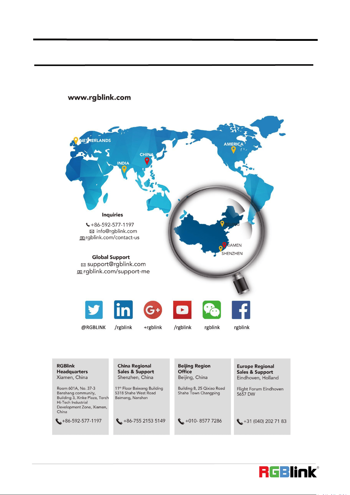
© Xiamen RGBlink Science & Technology Co., Ltd.
Ph: +86 592 5771197
60
Chapter 8 Support