VACUUM/FUEL PUMP TESTER MANUAL
W80594
PURPOSE OF THE VACUUM AND FUEL PUMP TESTER
This vacuum and fuel pump tester is designed for:
1. Quick accurate testing and setting of the carburetor.
2. Checking sticky valves.
3. Checking valve timing.
4. Detecting burnt valves or insufficient valve tappet clearance.
5.
Detecting weak valve springs, worn valve stem guides or leaking head gasket.
6. Testi
ng carburetor choke.
7. Fuel pump suction testing.
8. Fuel pump pressure testing.
WARNING: Not for use with Fuel Injection Systems. Damage to gauge will occur.
Note: Vacuum gauge readings are dependent on altitude and the gauge is calibrated
by the factory for sea level operation. For every 1,000 ft. above sea level, the vacuum
gauge will read low by one inch of vacuum or one division
on the dial.
Example: A reading of 20 inches vacuum at sea level would read only 19 inches at
1,000 ft. above sea level and 18 inches at 2,000 ft. above sea level.
CONNECTION FOR MANIFOLD VACUUM TEST: 1 thru 6
On some 4 and 6 cylinder engines, the intake manifold has a pipe plug that may be
removed and a adaptor may be used (See Fig. A). Make sure the connection is tight,
with no leaks, and there is suction.
On late model cars that are equipped with vacuum operated accessories, connect the
vacuum gauge in place of the accessory fitting on the intake manifold. (See Fig. B)
CAUTION: Before starting engine be sure gauge and hose are located away from
moving parts or hot manifold.
TEST 1: Testing and setting of the carburetor
Start the engine and allow sufficient time to reach normal operating temperature. With
the engine at normal idle speed(See your service manual specifications for idle speed)
the vacuum gauge should read in the range of 17-22 in. and should hold steady (See
chart, Fig. 1 and Fig. 2).
In making carburetor adjustments it is important that the engine speed be in the proper
range for slow and fast idle. While these speeds may be estimated by ear, the tests
are best performed using an Idle Tachometer which provides an accurate measure of
engine speed. If the vacuum is low and floating (See Chart, Fig. 3), adjust the idle
mixture screw either richer or leaner to give the highest vacuum reading without
appreciable vibration.
To make the high speed carburetor adjustment, set carburetor throttle on high idle
cam. Adjust the high speed mixture screw to give the highest vacuum reading without
appreciable vibration.
Note: Not all carburetors are equipped with a high speed mixture screw (See your
service manual).
TEST 2: Checking sticking valves
With engine running at idle speed; observe the vacuum gauge; if the pointer drops
intermittently about four divisions, the valves are sticking. (See Chart, Fig. 4). To
confirm this condition, inject penetrating oil into the intake manifold for temporary
relief. If the intermittent drop stops temporarily, the valves are sticking.
TEST 3: Valve timing
If valve timing is off any appreciable amount, the vacuum reading will be steady but
slow (See Chart, Fig. 5) and a high reading cannot be obtained. If the ignition timing is
off, the vacuum reading will also be steady but low (See Chart, Fig. 6).
TEST 4: Burnt valves or insufficient valve tappet clearance
If the valves are burnt, the vacuum reading will constantly drop whenever burnt valves
come into operation (See Chart, Fig. 7),
TEST 5: Weak valve springs, worn valve guides or
leaking head gasket
If the vacuum reading is normal and steady at idle speeds but the pointer vibrates
excessively at higher speeds, the valve springs are weak (See Chart, Fig. 8). If the
vacuum reading vibrates excessively at idling speeds, but the pointer steadies with the
increasing speed of the engine, the valve stem guides are worn (See Chart, Fig. 9). If
the pointer vibrates excessively at all speeds, look for a leaking head gasket (See
Chart, Fig. 10).
TEST 6: Choke test
Remove the high tension wire from the distributor and ground it. With the throttle
closed, crank the engine. A REMOTE STARTER SWITCH permits one person to
crank the engine from under the hood. If the pointer stays around 3-6 in. (See Chart,
Fig. 11), the choke valve is failing to close, the riser tube is burned or there are air
leaks in the manifold.
TEST 7: Fuel pump test
Disconnect the gasoline line from the tank to the fuel pump. Connect the vacuum
gauge to this point on the fuel pump. Start the engine (the gasoline in the carburetor
will generally run the engine for a few minutes before the engine will stop), the vacuum
gauge will build up to 10 in. vacuum if the fuel pump is in good condition.
FUEL PUMP PRESSURE TEST
Disconnect the gasoline line from the carburetor between the carburetor and the fuel
pump. Connect the vacuum gauge to the line connected to the fuel pump. Start the
engine and run it at idling speed. See manufacturers specifications for recommended
operating fuel pump pressure. The fuel pump pressure should hold for several minutes
after the engine is stopped before gradually dropping to zero. If the pressure drops
rapidly look for a worn pump valve, broken diaphragm or leaks around the diaphragm.
NOTE: The vacuum gauge is equipped with an impulse damper. This impulse damper
is located in the gauge fitting to which the hose is connected. This prevents excessive
pulsations of the pointer when making vacuum tests. This restriction or impulse
damper may become clogged after considerable use. It can be cleaned by pulling the
rubber hose from the gauge and using a stiff piece of wire of 0.043” dia. pushing it
through orifice.
NOTE: A bourbon tube vacuum gauge is a very delicate instrument and should be
handled and stored in the same manner as any expensive automotive test instrument.
In the event your gauge pointer shifts off “zero” the gauge can be corrected by:
1. Removing the chrome ring that holds the lens.
2. With needle nose pliers lift the pointer off the pivot. Use caution to avoid bending.
3. Reposition pointer to indicate “zero”. Press pointer down with fingers only. Caution:
Do not strike pointer with any object. Check pointer by trying to lift with fingers lightly.
4. Replace the lens and chrome ring by snapping into place.
Your gauge is now ready for use once again.
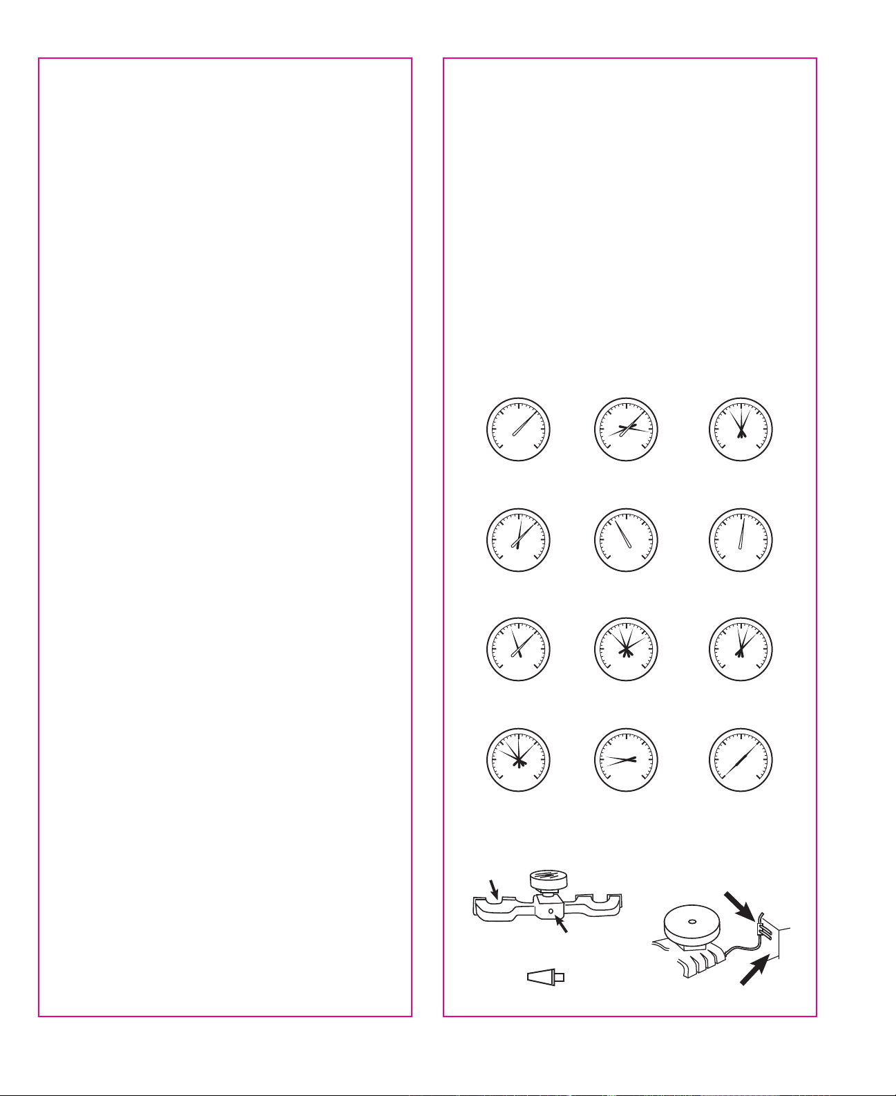
VACUUM DIAGNOSIS CHART
WHITE POINTER INDICATES STEADY HAND
BLACK POINTER INDICATES FLUCTUATING HAND
0
30
25
20
15
10
5
0
30
25
20
15
10
5
0
30
25
20
15
10
5
0
30
25
20
15
10
5
0
30
25
20
15
10
5
0
30
25
20
15
10
5
0
30
25
20
15
10
5
0
30
25
20
15
10
5
0
30
25
20
15
10
5
0
30
25
20
15
10
5
0
30
25
20
15
10
5
0
30
25
20
15
10
5
FIG. 1
FIG. 2
FIG. 3
FIG. 4
FIG. 5
FIG. 6
FIG. 7
FIG. 8
FIG. 9
FIG. 10
FIG. 11
FIG. 12
NORMAL MOTOR NORMAL MOTOR
(Opened & closed throttle,
rings & valves OK)
FAULTY CARBURETOR
ADJUSTMENT
STICKING VALVES LATE VALVE TIMING
LATE IGNITION TIMING
BURNT OR LEAKING
VALVES
WEAK VALVE SPRINGS
WORN VALVE GUIDES
LEAKING HEAD GASKET STUCK CHOKE VALVE,
LEAKING INTAKE OR
CARBURETOR GASKETS
CHOKED MUFFLER
FIG. A
FIG. B
FIG. C
VACUUM MANIFOLD
FIREWALL
INTAKE MANIFOLD
ADAPTOR
MANIFOLD
PIPE PLUG