PERFORMANCE TOOL extends only the following warranties, and only to original retail purchasers.
These warranties give specic legal rights. Except where prohibited by local law, the law of the State
of Washington governs all warranties and all exclusions and limitations of warranties and remedies.
There may be other rights which vary from state to state.
PERFORMANCE TOOL warrants the product to be free from defects in materials and workmanship
under normal use and service. A defective product may be returned for a free replacement within 90
days from the date of purchase, provided that product is returned to place of purchase immediately
after discovery of defect. After 90 days and up to 1 year from date of purchase, PERFORMANCE
TOOL will replace at no charge any parts which our examination shall disclose to be defective
and under warranty. These warranties shall be valid only when a sales receipt showing the date of
purchase accompanies the defective product or defective part(s) being returned. For part(s) after 90
days, please remit your request, postage prepaid to:
PERFORMANCE TOOL, P.O. Box 88259 Tukwila, WA 98138
These warranties exclude blades, bits, punches, dies, bulbs, fuses, and other consumables which
must be replaced under normal use and service. These warranties shall not apply to any product or
part which is used for a purpose for which it is not design or which has been repaired or altered in
any way so as to aect adversely its performance or reliability, nor shall these warranties apply to
any product or part which has been subject to misuse, neglect, accident or wear and tear incident
to normal use and service.
PERFORMANCE TOOL does not authorize any other person to make any warranty or to assume any
liability in connection with its products.
Except for warranties of title and the limited express warranties set forth above, PERFORMANCE
TOOL makes no express or implied warranties of any kind with respect to its products. In particular,
PERFORMANCE TOOL makes no implied warranty of merchantability and no implied warranty of
tness for any particular purpose, except that for goods purchased primarily for personal, family
or household use and not for commercial or business use, PERFORMANCE TOOL makes an
implied warranty of merchantability (and, if otherwise applicable, an implied warranty of tness for
a particular purpose), but only for the particular qualities or characteristics, and for the duration,
expressly warranted above. The laws on limitation of implied warranties may dier from state to
state, so the above limitations may not apply in all cases.
PERFORMANCE TOOL shall not be liable for consequential, incidental or special damages resulting
from or in any manner related to any product, or to the design, use, or any inability to use the product.
The sole and exclusive remedy for a defective product or part shall be the repair, or replacement
thereof as provided above. The laws on limitation of remedies or on consequential, incidental or
special damages may vary from state to state, so the above limitations may not apply in all cases.
P.O. Box 88259 • Tukwila, WA 98138 • 1-800-497-0552 • Made in China • © Copyright 2017 • www.wilmarcorp.com
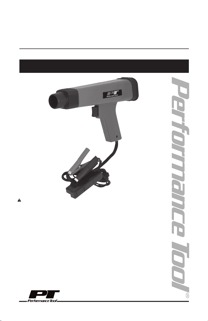
OWNER’S MANUAL
Item Number W80587
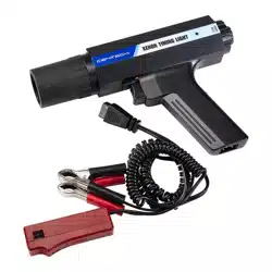
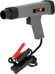
SELF POWERED
TIMING LIGHT
If you encounter any problems or difficulties, please contact our
customer service department at:
1-800-426-1262 between 6:30 a.m. and 4:30 p.m. Pacific time.
WARNING:
It is the owner and/or operators’ responsibility to study all WARNINGS, operating, and
maintenance instructions contained on the product label and instruction manual prior to
operation of this product. The owner/operator shall retain product instructions for future reference.
The owner and/or operator are responsible for maintenance, maintaining all decals or warning
labels and while in use, maintaining the unit in good working order. If the owner and/or operator
are not fluent in English, the product warnings and instructions shall be read and discussed with
the operators’ native language by the purchaser/owner or his designee. Make sure that the
operator comprehends its contents. Safety information shall be emphasized and understood prior
to usage. The product shall be inspected per the operating instructions.
Users of this product must fully understand these instructions. Each person operating this product
must also be of sound mind and body and must not be under the influence of any substance that
might impair their vision, dexterity or judgment.
Protect yourself and others by observing all safety information.
Failure to comply with instructions could result in personal injury and/or property damage!
If you encounter any problems or difficulties, please contact our customer service department at:
1-800-426-1262 between 6:30 a.m. and 4:30 p.m. Pacific time.
WARNING: This product and its packaging contain a chemical known to the State of California to
cause cancer, birth defects, or other reproductive harm.
WARNING: The warnings, cautions, and instructions discussed in this instruction manual cannot
cover all possible conditions and situations that may occur. It must be understood by the operator
that common sense and caution are factors which cannot be built into this product, but must be
supplied by the operator. Read and understand all of the instructions provided in the instruction
manual of this product, as well as, any other tool(s) used with this product.
LIMITED WARRANTY

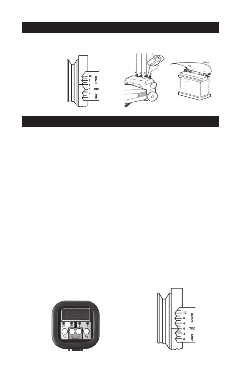
1.
Locate engine‐timing mark, see figure 1. Us a rag to clean all grease and dirt from the mark and
the pointer. It may help to use chalk or white paint on the marks to make them more easily seen.
2. Check manufacturer’s specifications for correct timing for engine being serviced.
3. Start and run engine until normal operating temperature is reached. Approximately 15 minutes.
Stop engine.
4.
If specifications require, locate the vacuum line going to the ignition distributor vacuum
advance and disconnect and plug the line. A golf tee or small pencil may be used to seal the line.
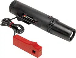
5. Connect the timing light as shown in figure 2.
6. Start engine and operate at normal idle speed. Aim the timing light at the timing mark, be
cautious of moving parts.
7. Trigger the timing light and observe the reading from timing mark.
CAUTION: Use care when working around moving engine. The stroboscopic action will make
moving parts appear to be in slow motion. Keep hands, tools and timing light clear of moving
fan, belts or other moving parts.
GENERAL OPERATING PROCEDURES CONT.
WHAT IS TIMING?
In order for an automobile engine to function, three things are necessary: air, fuel, and a spark to
ignite the air/fuel mixture and create an explosion. The precise instant of that explosion must be
such that the maximum power is delivered to the engine piston. This is “Timing.” Each engine
manufacturer determines at the factory the exact timing necessary for various engines so that each
ounce of power is obtained from every gallon of fuel. Due to normal engine and ignition system wear,
the timing can change and will reduce both power and mileage. With the Xenon timing light, the car
owner can reset the timing to the new car standards and regain lost power and increase mileage.
Timing is given in degrees Before Top Dead Center (BTDC) or After Top Dead Center (ATDC) in the
manufacturer’s specications. In order to completely burn the air/fuel mixture in the car’s engine cyl-
inders, most timing is such that the spark occurs at a point several degrees before top dead center
(for example, 4 BTDC) to assure that full power of the explosion is obtained. Two additional terms
that manufacturers use when describing timing are; “Advanced” and “Retarded.” When the timing is
advanced, the spark will occur before the piston reaches the top of the engine cylinder (BTDC). On
some late model cars equipped with various emission control devices, the timing is retarded so that
the spark occurs after the piston has started down in the cylinder (ATDC). Engine timing is changed
by adjustment of the ignition distributor.
In order to allow setting and adjustment of the engine timing, special “Timing Marks” are provided on
each engine during assembly. In most cases, these marks appear on the engine harmonic balancer
attached to the crank pulley at the lower front of the engine.
WHEN TO CHECK TIMING
The instant of spark plug ring is determined by the opening of the distributor ignition breaker points
and will change any time the point gap or dwell angle is changed. In addition, normal wear on the
breaker point‐rubbing block will have the same aect on the point gap or dwell angle. While cars
equipped with the new “breaker less Electronic ignition Systems” will not normally change timing
since there are no breaker points, the timing light can still be used to note changes in timing caused
by troubles in the ignition system as well as for resetting timing when components are changed or
the vehicle is tuned.
8. Compare reading obtained in step 7 with manufacturers specifications. If timing is not as
specified readjust as described in the following procedure
9. Stop engine.
TIMING SPECIFICATIONS
As noted in earlier paragraphs, timing requirements vary from engine to engine and for this reason
the engine manufacturer’s specification‐should always be referred to before making and adjustment.
These specifications are contained in the car owner’s manual, and typically on the under hood decal
specifications.
GENERAL OPERATING PROCEDURES
INSTRUCTIONS
Adjusting Timing to Specification
1. Loosen distributor hold down locking bolt located at base of distributor enough so that
distributor may be rotated back and forth, Do not over loosen or remove bolt but leave tight
enough to prevent distributor from turning by itself.
2. Start and warm engine to normal operating temperature
3. Direct timing light flash at timing marks and slowly rotate distributor right and left until timing
marks re aligned with pointer to factory spec., see figure 1 above.
4. Stop engine.
5. Tighten distributor hold down bolt‐using care not.
6. Start engine and recheck timing.
To use an advance timing light for checking the “Idle Timing”
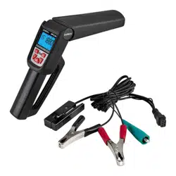
Adjust the advance to 0 (zero) on the timing light with the + an – buttons located on the back of the
timing light, see figure 3.
Follows the “Operating Procedures In General” from above.
1. Pull the trigger on the timing light, point the light at the timing mark on the vehicle.
2. Use the + or – buttons on the timing light see fig. 3, to move the mark to the 0 (zero) line on the
harmonic balancer in fig. 4
3. Look at the figure on the back of the timing light, this is your Idle Timing.
Checking the Centrifugal Advance and Vacuum Advance
1. Follows the “Operating Procedures In General” from above, except increase the engine speed
to 2000 rpm. Refer to factory owner’s manual for the recommended rpm.
2. Trigger the timing light and use the + an – buttons located on the back of the timing light. Stop
when the timing mark moves to TDC or O position.
3. Look at the figure on the back of the timing light, add this to your idle timing figure. This is
your Total Timing.
4. Compare the reading with manufacturer’s specification.
Fig. 1
Fig. 2
Fig. 3
Fig. 4
1.
Locate engine‐timing mark, see figure 1. Us a rag to clean all grease and dirt from the mark and
the pointer. It may help to use chalk or white paint on the marks to make them more easily seen.
2. Check manufacturer’s specifications for correct timing for engine being serviced.
3. Start and run engine until normal operating temperature is reached. Approximately 15 minutes.
Stop engine.
4.
If specifications require, locate the vacuum line going to the ignition distributor vacuum
advance and disconnect and plug the line. A golf tee or small pencil may be used to seal the line.
5. Connect the timing light as shown in figure 2.
6. Start engine and operate at normal idle speed. Aim the timing light at the timing mark, be
cautious of moving parts.
7. Trigger the timing light and observe the reading from timing mark.
CAUTION: Use care when working around moving engine. The stroboscopic action will make
moving parts appear to be in slow motion. Keep hands, tools and timing light clear of moving
fan, belts or other moving parts.
GENERAL OPERATING PROCEDURES CONT.
WHAT IS TIMING?
In order for an automobile engine to function, three things are necessary: air, fuel, and a spark to
ignite the air/fuel mixture and create an explosion. The precise instant of that explosion must be
such that the maximum power is delivered to the engine piston. This is “Timing.” Each engine
manufacturer determines at the factory the exact timing necessary for various engines so that each
ounce of power is obtained from every gallon of fuel. Due to normal engine and ignition system wear,
the timing can change and will reduce both power and mileage. With the Xenon timing light, the car
owner can reset the timing to the new car standards and regain lost power and increase mileage.
Timing is given in degrees Before Top Dead Center (BTDC) or After Top Dead Center (ATDC) in the
manufacturer’s specications. In order to completely burn the air/fuel mixture in the car’s engine cyl-
inders, most timing is such that the spark occurs at a point several degrees before top dead center
(for example, 4 BTDC) to assure that full power of the explosion is obtained. Two additional terms
that manufacturers use when describing timing are; “Advanced” and “Retarded.” When the timing is
advanced, the spark will occur before the piston reaches the top of the engine cylinder (BTDC). On
some late model cars equipped with various emission control devices, the timing is retarded so that
the spark occurs after the piston has started down in the cylinder (ATDC). Engine timing is changed
by adjustment of the ignition distributor.
In order to allow setting and adjustment of the engine timing, special “Timing Marks” are provided on
each engine during assembly. In most cases, these marks appear on the engine harmonic balancer
attached to the crank pulley at the lower front of the engine.
WHEN TO CHECK TIMING
The instant of spark plug ring is determined by the opening of the distributor ignition breaker points
and will change any time the point gap or dwell angle is changed. In addition, normal wear on the
breaker point‐rubbing block will have the same aect on the point gap or dwell angle. While cars
equipped with the new “breaker less Electronic ignition Systems” will not normally change timing
since there are no breaker points, the timing light can still be used to note changes in timing caused
by troubles in the ignition system as well as for resetting timing when components are changed or
the vehicle is tuned.
8. Compare reading obtained in step 7 with manufacturers specifications. If timing is not as
specified readjust as described in the following procedure
9. Stop engine.
TIMING SPECIFICATIONS
As noted in earlier paragraphs, timing requirements vary from engine to engine and for this reason
the engine manufacturer’s specification‐should always be referred to before making and adjustment.
These specifications are contained in the car owner’s manual, and typically on the under hood decal
specifications.
GENERAL OPERATING PROCEDURES
INSTRUCTIONS
Adjusting Timing to Specification
1. Loosen distributor hold down locking bolt located at base of distributor enough so that
distributor may be rotated back and forth, Do not over loosen or remove bolt but leave tight
enough to prevent distributor from turning by itself.
2. Start and warm engine to normal operating temperature
3. Direct timing light flash at timing marks and slowly rotate distributor right and left until timing
marks re aligned with pointer to factory spec., see figure 1 above.
4. Stop engine.
5. Tighten distributor hold down bolt‐using care not.
6. Start engine and recheck timing.
To use an advance timing light for checking the “Idle Timing”
Adjust the advance to 0 (zero) on the timing light with the + an – buttons located on the back of the
timing light, see figure 3.
Follows the “Operating Procedures In General” from above.
1. Pull the trigger on the timing light, point the light at the timing mark on the vehicle.
2. Use the + or – buttons on the timing light see fig. 3, to move the mark to the 0 (zero) line on the
harmonic balancer in fig. 4
3. Look at the figure on the back of the timing light, this is your Idle Timing.
Checking the Centrifugal Advance and Vacuum Advance
1. Follows the “Operating Procedures In General” from above, except increase the engine speed
to 2000 rpm. Refer to factory owner’s manual for the recommended rpm.
2. Trigger the timing light and use the + an – buttons located on the back of the timing light. Stop
when the timing mark moves to TDC or O position.
3. Look at the figure on the back of the timing light, add this to your idle timing figure. This is
your Total Timing.
4. Compare the reading with manufacturer’s specification.
Fig. 1
Fig. 2
Fig. 3
Fig. 4
INSTRUCTIONS CONT.
Rotary Engine
The timing Light can be used on rotary engines. Follow the manufacture’s specific instructions and
specifications. Below is a typical procedure for the Mazda twin rotor engine.
1. Connect the Red and Black power leads clamps to the battery. Connect wire with the spark
plug adaptor to the leading spark plug on the front rotor housing.
2. Start the engine and run at idle speed.
3. Aim the timing light at the timing indicator pin on the front cover
4. Loosen the distributor locking nuts and rotate the leading side distributor body until the timing
mark on the eccentric shaft pulley are in line with the timing indicator pin.
5. Tighten the locking nuts and recheck the timing.
6. Repeat the above step for setting the trailing side distributor timing with the timing light
connected to the trailing spark plug.
Ail timing lights are tested 100% before they are shipped from the factory and improper operation is
usually caused by incorrect hook‐up. Please observe the above trouble shooting procedure if the
timing light fails to perform satisfactorily.
INSTRUCTIONS CONT.
Testing Centrifugal Advance
1. With the timing light still connected and with the vacuum line disconnected:
2. Speed the engine up slowly and watch the timing mark.
3. The timing mark should remain stationary until the engine reaches the manufactures specified
speed. The timing mark should then move steadily and without jerking.
4. If the mark does not move, or if it moves erratically, the centrifugal (automatic) advance should
be serviced as necessary.
5. To check the maximum advance stop the engine.
6. It’s necessary to mark the harmonic balance with the maximum degree per manufacturer’s
specifications and follow manufacture’ procedures.
Testing Vacuum Advance
1. The vacuum line to the distributor must be connected to make this test.
2. Set engine speed to 800 R.P.M or speed necessary to apply vacuum to distributor.
3. Aim the timing light and note position of the timing Mark.
4. Disconnect vacuum line.
5. If the timing mark does not move, the trouble could be a plugged line. A leaky diaphragm or a
frozen distributor Plate, and the distributor should be serviced as required.
Checking Distributor Cam Wear
1. This check is done after the timing has been set and the timing mark lines up with the
reference pointer for #1 cylinder.
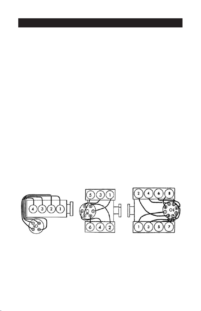
2. Connect the timing light to the wire directly opposite (180) #1 cylinder on the distributor cap,
see figure 5.
3. Start engine and aim the timing light towards the timing mark. The reading should be the same
as when connected to #1 cylinder.
4. If reading is not the same, probable cause is worm out distributor cam or bent distributor shaft.
Repair as required.
4-Cyl move from #1 to #4 6-Cyl move from #1 to #4 8-Cyl move from #1 to #6
Small Engines
The DC power Timing Light can be used on any combustion engine with impulse ignition, magneto
ignition, such as motorcycle, lawn mowers, outboard motors, or any time there is a high voltage
spark used for ignition.
When 12 Volt DC voltage is not available from the engine being tested, an external battery of 12V
must be used. Connect a ground from the negative post of the external battery to the engine.
Connect the red clip to the (+) positive terminal and the black clip to the (‐) negative terminal of the
battery. Connect the adaptor lead of the timing light to proper spark plug.
TROUBLE SHOOTING
SYMPTOM PROBABLE CAUSE SOLUTION
No Flash Switch in “OFF” position.
Move switch to “ON” position.
Battery clips connected Reverse the battery clip
backwards. connection.
Poor connection of clips. Make sure the clip is
connected to a clean
battery post.
No Flash but double Wrong direction of Toward the arrow on
check indictor is “ON” inductive clamp. clamp to #1 plug.
Weak ignition or spark plug. Connect to other plugs or
The gap is too close. spark plug wires. If ashes
then repair the plug gap.
Fault Lamp Replace it.
Light Flashes Intermittently Timing light high-tension Place the high tension wire
wire lying on or too close in good order so it is routed
to the other spark plug wires.
away from the other spark
plug wires.

INSTRUCTIONS CONT.
Rotary Engine
The timing Light can be used on rotary engines. Follow the manufacture’s specific instructions and
specifications. Below is a typical procedure for the Mazda twin rotor engine.
1. Connect the Red and Black power leads clamps to the battery. Connect wire with the spark
plug adaptor to the leading spark plug on the front rotor housing.
2. Start the engine and run at idle speed.
3. Aim the timing light at the timing indicator pin on the front cover
4. Loosen the distributor locking nuts and rotate the leading side distributor body until the timing
mark on the eccentric shaft pulley are in line with the timing indicator pin.
5. Tighten the locking nuts and recheck the timing.
6. Repeat the above step for setting the trailing side distributor timing with the timing light
connected to the trailing spark plug.
Ail timing lights are tested 100% before they are shipped from the factory and improper operation is
usually caused by incorrect hook‐up. Please observe the above trouble shooting procedure if the
timing light fails to perform satisfactorily.
INSTRUCTIONS CONT.
Testing Centrifugal Advance
1. With the timing light still connected and with the vacuum line disconnected:
2. Speed the engine up slowly and watch the timing mark.
3. The timing mark should remain stationary until the engine reaches the manufactures specified
speed. The timing mark should then move steadily and without jerking.
4. If the mark does not move, or if it moves erratically, the centrifugal (automatic) advance should
be serviced as necessary.
5. To check the maximum advance stop the engine.
6. It’s necessary to mark the harmonic balance with the maximum degree per manufacturer’s
specifications and follow manufacture’ procedures.
Testing Vacuum Advance
1. The vacuum line to the distributor must be connected to make this test.
2. Set engine speed to 800 R.P.M or speed necessary to apply vacuum to distributor.
3. Aim the timing light and note position of the timing Mark.
4. Disconnect vacuum line.
5. If the timing mark does not move, the trouble could be a plugged line. A leaky diaphragm or a
frozen distributor Plate, and the distributor should be serviced as required.
Checking Distributor Cam Wear
1. This check is done after the timing has been set and the timing mark lines up with the
reference pointer for #1 cylinder.
2. Connect the timing light to the wire directly opposite (180) #1 cylinder on the distributor cap,
see figure 5.
3. Start engine and aim the timing light towards the timing mark. The reading should be the same
as when connected to #1 cylinder.
4. If reading is not the same, probable cause is worm out distributor cam or bent distributor shaft.
Repair as required.
4-Cyl move from #1 to #4 6-Cyl move from #1 to #4 8-Cyl move from #1 to #6
Small Engines
The DC power Timing Light can be used on any combustion engine with impulse ignition, magneto
ignition, such as motorcycle, lawn mowers, outboard motors, or any time there is a high voltage
spark used for ignition.
When 12 Volt DC voltage is not available from the engine being tested, an external battery of 12V
must be used. Connect a ground from the negative post of the external battery to the engine.
Connect the red clip to the (+) positive terminal and the black clip to the (‐) negative terminal of the
battery. Connect the adaptor lead of the timing light to proper spark plug.
TROUBLE SHOOTING
SYMPTOM PROBABLE CAUSE SOLUTION
No Flash Switch in “OFF” position.
Move switch to “ON” position.
Battery clips connected Reverse the battery clip
backwards. connection.
Poor connection of clips. Make sure the clip is
connected to a clean
battery post.
No Flash but double Wrong direction of Toward the arrow on
check indictor is “ON” inductive clamp. clamp to #1 plug.
Weak ignition or spark plug. Connect to other plugs or
The gap is too close. spark plug wires. If ashes
then repair the plug gap.
Fault Lamp Replace it.
Light Flashes Intermittently Timing light high-tension Place the high tension wire
wire lying on or too close in good order so it is routed
to the other spark plug wires.
away from the other spark
plug wires.

PERFORMANCE TOOL extends only the following warranties, and only to original retail purchasers.
These warranties give specic legal rights. Except where prohibited by local law, the law of the State
of Washington governs all warranties and all exclusions and limitations of warranties and remedies.
There may be other rights which vary from state to state.
PERFORMANCE TOOL warrants the product to be free from defects in materials and workmanship
under normal use and service. A defective product may be returned for a free replacement within 90
days from the date of purchase, provided that product is returned to place of purchase immediately
after discovery of defect. After 90 days and up to 1 year from date of purchase, PERFORMANCE
TOOL will replace at no charge any parts which our examination shall disclose to be defective
and under warranty. These warranties shall be valid only when a sales receipt showing the date of
purchase accompanies the defective product or defective part(s) being returned. For part(s) after 90
days, please remit your request, postage prepaid to:
PERFORMANCE TOOL, P.O. Box 88259 Tukwila, WA 98138
These warranties exclude blades, bits, punches, dies, bulbs, fuses, and other consumables which
must be replaced under normal use and service. These warranties shall not apply to any product or
part which is used for a purpose for which it is not design or which has been repaired or altered in
any way so as to aect adversely its performance or reliability, nor shall these warranties apply to
any product or part which has been subject to misuse, neglect, accident or wear and tear incident
to normal use and service.
PERFORMANCE TOOL does not authorize any other person to make any warranty or to assume any
liability in connection with its products.
Except for warranties of title and the limited express warranties set forth above, PERFORMANCE
TOOL makes no express or implied warranties of any kind with respect to its products. In particular,
PERFORMANCE TOOL makes no implied warranty of merchantability and no implied warranty of
tness for any particular purpose, except that for goods purchased primarily for personal, family
or household use and not for commercial or business use, PERFORMANCE TOOL makes an
implied warranty of merchantability (and, if otherwise applicable, an implied warranty of tness for
a particular purpose), but only for the particular qualities or characteristics, and for the duration,
expressly warranted above. The laws on limitation of implied warranties may dier from state to
state, so the above limitations may not apply in all cases.
PERFORMANCE TOOL shall not be liable for consequential, incidental or special damages resulting
from or in any manner related to any product, or to the design, use, or any inability to use the product.
The sole and exclusive remedy for a defective product or part shall be the repair, or replacement
thereof as provided above. The laws on limitation of remedies or on consequential, incidental or
special damages may vary from state to state, so the above limitations may not apply in all cases.
P.O. Box 88259 • Tukwila, WA 98138 • 1-800-497-0552 • Made in China • © Copyright 2017 • www.wilmarcorp.com
OWNER’S MANUAL
Item Number W80587
SELF POWERED
TIMING LIGHT
If you encounter any problems or difficulties, please contact our
customer service department at:
1-800-426-1262 between 6:30 a.m. and 4:30 p.m. Pacific time.
WARNING:
It is the owner and/or operators’ responsibility to study all WARNINGS, operating, and
maintenance instructions contained on the product label and instruction manual prior to
operation of this product. The owner/operator shall retain product instructions for future reference.
The owner and/or operator are responsible for maintenance, maintaining all decals or warning
labels and while in use, maintaining the unit in good working order. If the owner and/or operator
are not fluent in English, the product warnings and instructions shall be read and discussed with
the operators’ native language by the purchaser/owner or his designee. Make sure that the
operator comprehends its contents. Safety information shall be emphasized and understood prior
to usage. The product shall be inspected per the operating instructions.
Users of this product must fully understand these instructions. Each person operating this product
must also be of sound mind and body and must not be under the influence of any substance that
might impair their vision, dexterity or judgment.
Protect yourself and others by observing all safety information.
Failure to comply with instructions could result in personal injury and/or property damage!
If you encounter any problems or difficulties, please contact our customer service department at:
1-800-426-1262 between 6:30 a.m. and 4:30 p.m. Pacific time.
WARNING: This product and its packaging contain a chemical known to the State of California to
cause cancer, birth defects, or other reproductive harm.
WARNING: The warnings, cautions, and instructions discussed in this instruction manual cannot
cover all possible conditions and situations that may occur. It must be understood by the operator
that common sense and caution are factors which cannot be built into this product, but must be
supplied by the operator. Read and understand all of the instructions provided in the instruction
manual of this product, as well as, any other tool(s) used with this product.
LIMITED WARRANTY