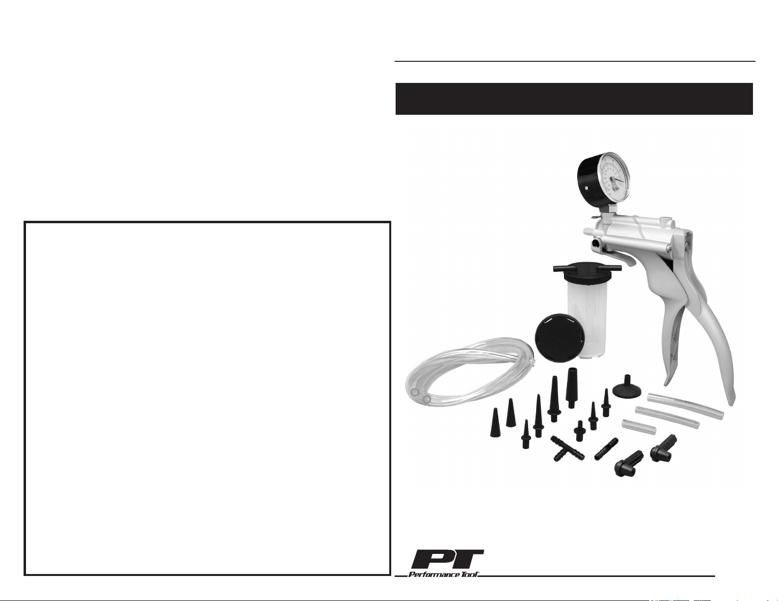
Vacuum Pump
OWNER'S MANUAL
Stock Number W87030
FOR YOUR SAFETY,
please read these instructions carefully and retain them for future use.
LIMITED WARRANTY
PERFORMANCE TOOL extends only the following warranties, and only to original retail purchasers.
These warranties give specific legal rights. Except where prohibited by local law, the law of the State of
Washington governs all warranties and all exclusions and limitations of warranties and remedies. There
may be other rights which vary from state to state.
PERFORMANCE TOOL warrants the product to be free from defects in materials and workmanship
under normal use and service. A defective product may be returned for a free replacement within 90
days from the date of purchase, provided that product is returned to place of purchase immediately
after discovery of defect. After 90 days and up to 1 year from date of purchase, PERFORMANCE
TOOL will replace at no charge any parts which our examination shall disclose to be defective
and under warranty. These warranties shall be valid only when a sales receipt showing the date of
purchase accompanies the defective product or defective part(s) being returned. For part(s) after 90
days, please remit your request, postage prepaid to: PERFORMANCE TOOL, P.O. Box 24086 Seattle,
WA 98124
These warranties exclude blades, bits, punches, dies, bulbs, fuses, and other consumables which
must be replaced under normal use and service. These warranties shall not apply to any product or
part which is used for a purpose for which it is not designed, or which has been repaired or altered in
any way so as to affect adversely its performance or reliability, nor shall these warranties apply to any
product or part which has been subject to misuse, neglect, accident or wear and tear incident to normal
use and service.
PERFORMANCE TOOL does not authorize any other person to make any warranty or to assume any
liability in connection with its products.
Except for warranties of title and the limited express warranties set forth above, PERFORMANCE
TOOL makes no express or implied warranties of any kind with respect to its products. In particular,
PERFORMANCE TOOL makes no implied warranty of merchantability and no implied warranty of
fitness for any particular purpose, except that for goods purchased primarily for personal, family or
household use and not for commercial or business use, PERFORMANCE TOOL makes an implied
warranty of merchantability (and, if otherwise applicable, an implied warranty of fitness for a particular
purpose), but only for the particular qualities or characteristics, and for the duration, expressly
warranted above. The laws on limitation of implied warranties may differ from state to state, so the
above limitations may not apply in all cases.
PERFORMANCE TOOL shall not be liable for consequential, incidental or special damages resulting
from or in any manner related to any product, or to the design, use, or any inability to use the product.
The sole and exclusive remedy for a defective product or part shall be the repair, or replacement
thereof as provided above. The laws on limitation of remedies or on consequential, incidental or special
damages may vary from state to state, so the above limitations may not apply in all cases.
Copyright © 2017 PERFORMANCE TOOL – All rights reserved
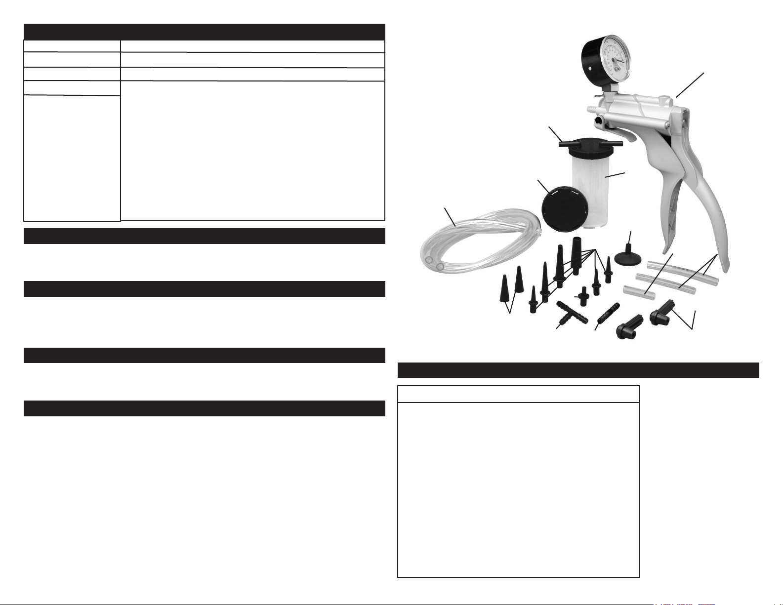
PARTS LIST
PRODUCT SPECIFICATIONS
Item Description
Gauge Size 2 in. Diameter
Gauge Scale 0,-.30 in/Hg (0<->76 cm/Hg) Vacuum
Accessories 1/4 in. I.D. X 23" Long Vacuum Hoses (Qty. 2)
1/4 in. I.D. X 3" Long Vacuum Hoses (Qty. 2)
1/4 in. I.D. X 2" Long Vacuum Hoses (Qty. 1)
Tapered Hose Adapters (Qty. 6)
”T” Hose Connector, Straight Hose Connector
Brake Bleeder Valve Adapters (Qty. 2)
Universal Cup Adapter
Vacuum Hose Adapter, Plugs (Qty.2)
4 oz. Reservoir Jar, Jar Lids (Qty. 2)
Net Weight 1.8 Lbs
When unpacking, check to make sure all the parts shown on the parts list on pg. are in-
cluded. If any parts are missing or broken, please call customer support at 1-800-497-0552
You will need this manual for the safety warnings and precautions, assembly, operating,
inspection, maintenance and cleaning procedures, parts list and assembly diagram. Keep
your invoice with this manual. Write the invoice number on the inside of the front cover.
Keep this manual and invoice in a safe and dry place for future reference.
Keep bystanders, children, and visitors away while operating the Brake Bleeder/Vacuum
Pump. Distractions can cause you to lose control. Protect others in the work area from
injury. Provide barriers or shields as needed.
PERSONAL SAFETY
1. Stay alert. Watch what you are doing, and use common sense when operating the Brake
Bleeder/Vacuum Pump. Do not use the tool while tired or under the inuence of drugs,
alcohol, or medication. A moment of inattention while operating the tool may result in
serious personal injury.
2. Dress properly. Do not wear loose clothing or jewelry. Contain long hair. Keep your hair,
clothing, and jewelry away from moving parts. Loose clothes, jewelry, or long hair can be
caught in moving parts.
3. Do not overreach. Keep proper footing and balance at all times. Proper footing and
balance enables better control of the power tool in unexpected situations.
4. Use safety equipment. Always wear ANSI approved safety glasses underneath a full
face safety shield. Nonskid safety shoes, hard hat, or hearing protection must be used for
appropriate conditions.
UNPACKING
SAVE THIS MANUAL
GENERAL SAFETY RULES
PERSONAL SAFETY
2
7
2a
3
4
56
7
11
9
1
8
Part Description Qty.
1 Brake Bleeder/Vacuum Pump 1
2a Jar Lid (for operation) 1
2b Jar Lid (for transport) 1
3 Reservoir Jar 1
4 23" Vacuum Hose 2
5 3" Vacuum Hose 2
6 2" Vacuum Hose 1
7 Tapered Hose Adapter 6
8 “T” Hose Connector 1
9 Straight Hose Connector 1
10 Brake Bleeder Screw Adapter 2
11 Universal Cup Adapter 1
12 Plug 2
13 Vacuum Hose Adapter 2
2b
10
12
13
NOTE: Some parts are listed and
shown for illustration purposes only,
and are not available individually as
replacement parts.

INSPECTION, MAINTENANCE AND CLEANING
1. WARNING! Always release the vacuum in the Brake Bleeder/Vacuum Pump before
performing any inspection, maintenance, or cleaning.
2.
Before each use: Inspect the general condition of the Brake Bleeder/Vacuum Pump.
Check for misalignment or binding of moving parts, cracked or broken parts, damaged Hoses,
loose connections, and any other condition that may affect its safe operation. If a problem
occurs, have the problem corrected before further use. Do not use damaged equipment.
3.
When cleaning: Do not clean the Brake Bleeder/Vacuum Pump with cleaners or other
solvents not intended for use with plastic components. Use a clean cloth and, if necessary, a
mild detergent. Do not immerse the Brake Bleeder/Vacuum Pump (1) component in any liquid.
4. When storing: Never store uid in the Reservoir Jar (3) of the Brake Bleeder/Vacuum
Pump. Always dispose of excess uid properly, according to federal, Pump (1) component
in any liquid.
5. WARNING! All maintenance, service, or repairs not listed in this manual are only to be
attempted by a qualied service technician.
Tool service must be performed only by qualied repair personnel. Service or maintenance
performed by unqualied personnel could result in a risk of injury.
When servicing a tool, use only identical replacement parts. Follow instructions in the
“Inspection, Maintenance, And Cleaning” section of this manual. Use of unauthorized parts
or failure to follow maintenance instructions may create a risk of injury.
Item Description
1. Do not force the tool. Use the correct tool for your application. The correct tool will do
the job better and safer at the rate for which it is designed.
2. Store idle tools out of reach of children and other untrained persons. Tools are danger-
ous in the hands of untrained users.
3. Maintain tools with care. Keep tools dry and clean. Properly maintained tools are less
likely to bind and are easier to control. Do not use a damaged tool. Tag damaged tools “Do
not use” until repaired.
4. Check for misalignment or binding of moving parts, breakage of parts, and any other
condition that may affect the tool’s operation. If damaged, have the tool serviced before
using. Many accidents are caused by poorly maintained tools.
5. Use only accessories that are recommended by the manufacturer for your model. Acces-
sories that may be suitable for one tool may become hazardous when used on another tool.
SPECIFIC SAFETY RULES
1. Maintain a safe working environment. Keep the work area well lit. Make sure there is
adequate surrounding workspace. Always keep the work area free of obstructions, grease, oil,
trash, and other debris. Do not use the Brake Bleeder/Vacuum Pump in areas near ammable
chemicals, dusts, and vapors. Do not use this product in a damp or wet location.
2. Maintain labels and nameplates on this product. These carry important information. If
unreadable or missing, contact Performance Tool for a replacement.
3. Keep the Handles of the Brake Bleeder dry, clean, and free from brake uid, oil, and grease.
4.
Prior to using the Brake Bleeder/Vacuum Pump make sure to read and understand all warnings,
safety precautions, and instructions as outlined in the vehicle manufacturer’s instruction manual.
Every vehicle has specic measurement values for vacuum related readings. It is beyond the
scope of this manual to properly describe the correct procedure and test data for each vehicle.
5. WARNING! Carbon monoxide is produced while a vehicle’s engine is operating and is deadly
in a closed environment. Early signs of carbon monoxide poisoning resemble the u, with
headaches, dizziness, or nausea. If you have these signs, the work area may not be vented
properly. Get fresh air immediately.
6. Prior to using the Brake Bleeder/Vacuum Pump, make sure to place the vehicle’s transmission
in “PARK” (if automatic) or “NEUTRAL” (if manual). Then, block the tires with chocks.
7. Be alert for hot engine parts to avoid accidental burns.
8.
Avoid accidental re and/or explosion. Do not smoke near engine fuel and battery components.
9.
Use the Brake Bleeder only with brake uid. Do not attempt to use the tool to siphon any other
liquids. Damage to the internal chamber and seal, or future brake uid contamination may result.
10. Follow guidelines for proper brake uid disposal. Used brake uid should be removed from
the vehicle and properly recycled. Many states require recycling. Contact your local solid/liquid
waste authority for information on recycling. Do not reuse old brake uid.
11.
Brake uid is corrosive. Avoid spilling it on the vehicle’s exterior, it can harm automobile paint.
12.
WARNING! People with pacemakers should consult their physician(s) before using this product
on a running engine. Electromagnetic elds in close proximity to a heart pacemaker could cause
interference or failure of the pacemaker. In addition, people with pacemakers should adhere to the
following: Caution is necessary when near the coil, spark plug cables, or distributor of a running
engine. The engine should always be off if adjustments are to be made to the distributor.
13. WARNING! The brass components of this product contain lead, a chemical known to the
State of California to cause cancer and birth defects (or other reproductive harm). (California
Health & Safety Code § 25249, et seq.)
14. WARNING! The warnings, precautions, and instructions discussed in this manual cannot
cover all possible conditions and situations that may occur. The operator must understand that
common sense and caution are factors which can not be built into this product, but must be
supplied by the operator.
TOOL USE AND CARE
SPECIFIC SAFETY RULES
3
INSPECTION, MAINTENANCE AND CLEANING
6
SERVICE
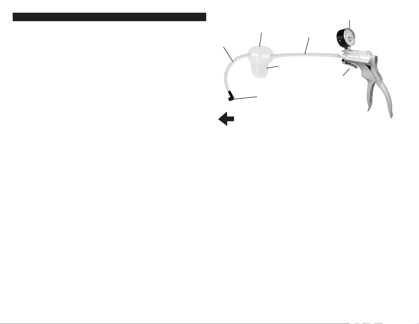
1. Attach a 3” Vacuum Hose (5) to the bottom of the Jar Lid (2a). (See Figure A.)
2. Attach a 23” Vacuum Hose (4) to the top of the Jar Lid (2a) marked “TO PUMP”. Then, attach the
other end of the 23” Vacuum Hose to the Brake Bleeder/Vacuum Pump (1). (See Figure A.)
3. Firmly attach the Jar Lid (2a) to the Reservoir Jar (3). (See Figure A.)
4. Remove the cap from the vehicle’s master cylinder, and check to make sure the master cylinder is
full of brake uid. If not full, ll the master cylinder to capacity with clean, new brake uid. (Use only
the kind of brake uid recommended by the vehicle manufacturer.)
5. NOTE: Determine the proper brake bleeding sequence from your vehicle service manual (i.e., right
rear wheel, left rear wheel, right front wheel, left front wheel).
6. Connect the 23” Vacuum Hose (4) to the remaining port on the Jar Lid (2a) and then connect the
other end to the Brake Bleeder Screw Adapter (9).
7.Squeeze the Handle of the Brake Bleeder/Vacuum Pump (1) a few times to create a vacuum
in its Reservoir Jar (3). NOTE: The Gauge on the Brake Bleeder/Vacuum Pump should read at
approximately 10 in/Hg. Do not exceed 20 in/Hg. A greater vacuum could damage the vehicle’s
brake system.
8. Once the Brake Bleeder/Vacuum Pump (1) is ready, check for leaks at the Reservoir Jar (3) and
at all Vacuum Hose (4, 5) connections. If there is a leak, release the vacuum in the Brake Bleeder/
Vacuum Pump with the Vacuum Release Control. CAUTION! NEVER remove the Jar Lid (2a) before
releasing the vacuum in the Brake Bleeder/Vacuum Pump. Correct the leak, and once again create a
vacuum in the Brake Bleeder/Vacuum Pump to approximately 10 in/Hg.
9. Open the vehicle’s wheel caliper bleeder screw, and allow brake uid to ow into the Reservoir Jar
(3). Then, retighten the wheel caliper bleeder screw after bleeding.
10. Release the vacuum in the Brake Bleeder/Vacuum Pump (1) with the Vacuum Release Control.
Then, disconnect the Brake Bleeder Screw Adapter (9) from the vehicle’s wheel caliper bleeder screw.
11. NOTE: When necessary, release the vacuum in the tool and empty its Reservoir Jar (3) of old
brake uid. To assist in transport, this set includes a leak-resistant Lid (2b) without hose connections.
After the brake uid is disposed of properly, resume bleeding the brakes.
12. Remove the cap from the vehicle’s master cylinder, and rell the master cylinder back to its normal
capacity with clean, new brake uid. Then, replace the cap on the master cylinder.
13. Proceed to the vehicle’s next wheel, and perform the same steps as above.
14. When nished using the Brake Bleeder/Vacuum Pump, clean the tool and store it in a clean, dry
location out of reach of children.
15.
WARNING! Before driving the vehicle, carefully check for leaks and test for proper
brake operation.
ASSEMBLY AND OPERATING INSTRUCTIONS
Figure A
3"
VACUUM
HOSE (5)
JAR LID (2a)
23" VACUUM
HOSE (4)
GAUGE
VACUUM
RELEASE
CONTROL
BRAKE BLEEDER
SCREW ADAPTER (9)
TO WHEEL CALIPER
BLEEDER SCREW
RESERVOIR
JAR (3)
4
5