Loading ...
Loading ...
Loading ...

English 5
For the operation of this system the fol-
lowing regulations and directives are
applicable in the Federal Republic of
Germany (available from Carl Hey-
manns Verlag KG, Luxemburger
Straße 449, 50939 Cologne):
– BGV D 26 Spray jet tasks
– Executing instructions for BGV D 26
– BGR 117 Working in closed rooms
– BGR 189 Using safety gear
– BGR 195 Using of safety gloves
– BGI 534 Working in closed rooms
– BGI 836 Gas warner
Î Release the trigger of the jet pistol.
Î Press emergency-stop button.
The dry ice dosing is topped and the air
flow from the nozzle is interrupted.
Î Interrupt the compressed air supply.
The machine is used to remove dirt us-
ing dry ice pellets that are speeded up
using an air jet.
The machine should not be operated in
explosive environments.
Use only dry ice pellets as jet medium.
Using any other jet medium can cause
damage to the machine.
The air pressure reaches the jet pistol
via a pressure regulation valve. The
valve opens when the trigger of the jet
pistol is pressed and the air flow comes
out from the jet pistol. Additionally, dry
ice pellets are dosaged into the air
stream via the dosing device. With the
version "IB 7/40 Advanced" the addi-
tional dosing can be switched off at the
jet pistol. The dry ice pellets hit the sur-
face to be cleaned and remove the dirt.
Additional heat currents are formed be-
tween the dirt and the object to be
cleaned by the -79 °C cold dry ice pel-
lets; this results in the dirt being loos-
ened. At the same time, dry ice
immediately gets coverted into gas-
eous carbon dioxide on contact and re-
quires 700 times the volume of dry ice.
Thus, the dirt penetrated by the dry ice
thus gets thrown off.
During the spraying operation through
the jet, a vibrator located on the dry ice
container ensures continuous sliding of
the dry ice pellets.
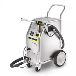
1 Push handle
2 Cover of the dry ice container
3 Holder for jet pistol
4
Storage compartment for accessories
5 Operating field
6 Coupling of the control cable
7 Earthing rope with clamp (only IB 7/
40 Advanced, option for IB 7/40
Classic)
8 Coupling spray agent hose
9 Guiding roll with fixed position brake
10 Transport handle, bumper at the rear
11
Dry ice outlet for emptying the container
1 Cable clamp
2 Mains cable with mains plug
3 Pressure relief valve, condensate
draining of the water separator
4 Compressed air connection
5 Condensate drain-out
6 Fuse F1, below the side panel
1 Statistics key, reset counter
2 Key to empty the dry ice container
3 Display
4 Key "increase jet pressure"
5 Key "decrease jet pressure"
6 Increase the dry ice dosing
7 Decrease the dry ice dosing
8 Power switch
9 Emergency-stop button
10 Key switch
1 Indicator lamp - control voltage
green: Control voltage OK
red: Control voltage too low
yellow: Emptying of dry ice contain-
er active
2 Indicator lamp emergency STOP
red: Emergency stop button activated
green: Emergency stop button not
activated
3 Indicator lamp - compressed air
green: Pressure OK
orange: selected jet pressure not
reached
red: Pressure too low (below
22 PSI/0.15 MPa)
4 Indicator lamp – dosing device
green: Drive OK
red: Error in drive
5 Indicator lamp - jet pistol
green: Jet pistol OK
orange: The trigger of the jet pistol
was activated during the switch-on
process
red: Jet pistol disconnected or con-
trol line damaged
6 Display field
Specifications and Guidelines
Switch-off in case of emergency
Proper use
Function
Control elements
Device
Operating field
Display
Loading ...
Loading ...
Loading ...