Loading ...
Loading ...
Loading ...
9
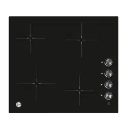
➢ The “blue” neutral wire must be connected to the terminal marked with letter (N)
- the live wire(L1) must be connected to the terminal marked with letter (L1)
(220-240V 1N~).
➢ The “blue” neutral wire must be connected to the terminal marked with letter (N)
- the live wire L1 must be connected to the terminal marked with letter (L1),. the
live wire L2 must be connected to the terminal marked with letter (L2) (380-
420V 2N~).
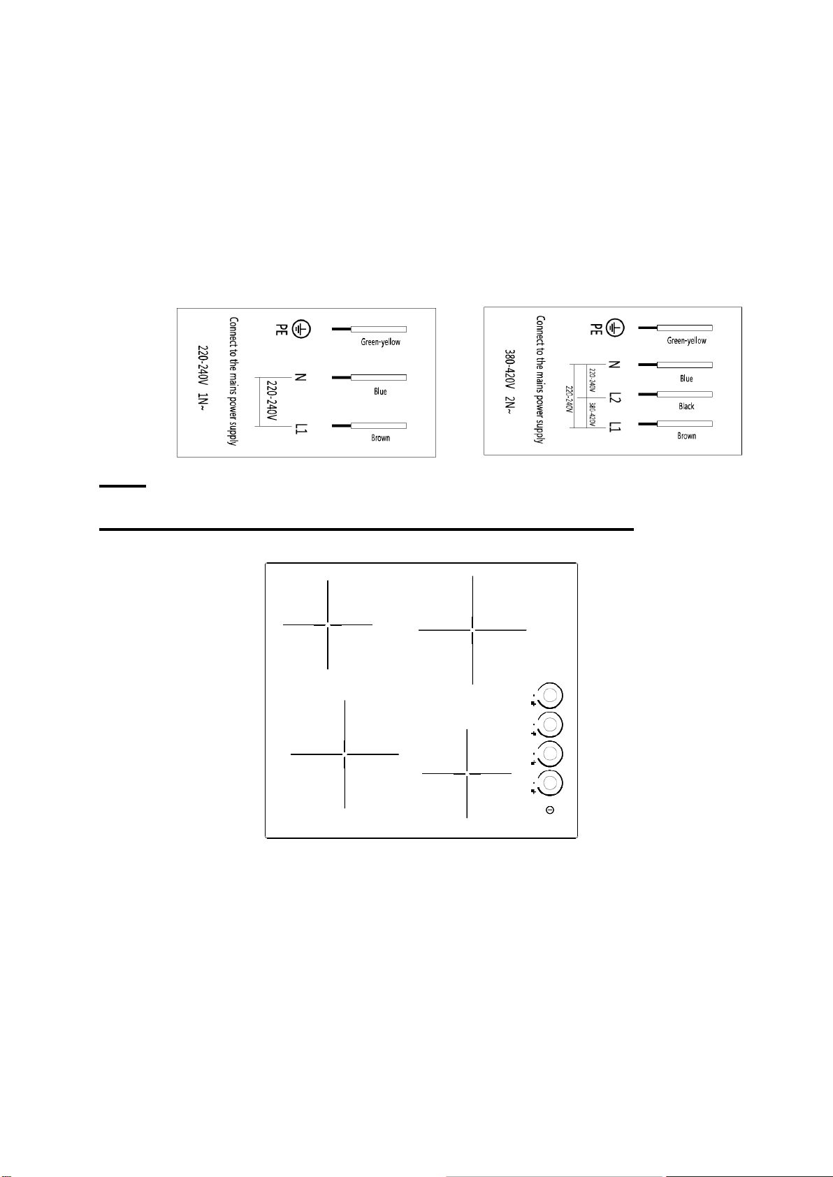
Des
cription of the Ceramic hob surface layout
4 zone ceramic hob schematic diagram
Display mode and control
1.1 Display mode
✓ Cooking zone working indicator: the corresponding indicator light display when the
cooking zone is working;
✓ Cooking zone residual heat indicator: the corresponding indicator flashes when the
cooking zone stops working (once every 1 second);
✓ The whole hob standby mode indicator: all cooking zone indicator lights alternately
turn on and off .
Loading ...
Loading ...
Loading ...