Loading ...
Loading ...
Loading ...
8 31-5000485 Rev. 4
INSTALLATION INSTRUCTIONS
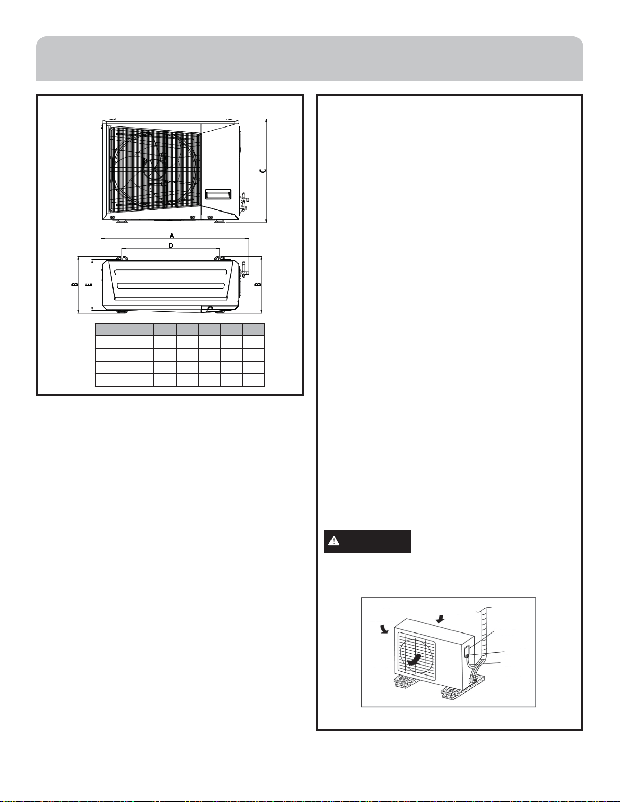
Dimensions
Model A B C D E
12K 33.5 13.6 21.9 20.0 11.0
18K 36.0 15.0 27.6 21.4 12.8
24K/30K/36K 40.0 17.5 31.9 26.4 15.2
48K 43.3 20.8 34.3 25.0 17.4
Unit Wiring
Electrical Wiring and Supply Voltage:
All wiring must comply with national, state, and local
codes.
Nameplate data indicates the operating voltage, phase,
ampacity, maximum over current protection, and
minimum voltage.
Install a field-supplied individual branch circuit with
current protection for the unit as required by code. Run
power supply wiring through a weatherproof disconnect
box in conduit to the unit connections. Disconnects are
required to be within sight and easy reach of the unit
(usually within 3 feet).
Always refer to the unit wiring diagram for the number of
conductors required. Route neatly and protect from sharp
edges and damage.
Inadequate wiring and improper power supply will likely
result in component failure and will void the warranty.
NOTE: The supply voltage must be consistent with the
rated voltage, not to exceed +/- 10%. Ensure the unit is
properly grounded.
Wiring Connections:
1. Remove the electrical control cover from the outdoor unit.
2. Connect the cables to the identified terminals on
the terminal block. 18 gauge thermostat wire is
recommended; however, national and local codes
prevail.
3. Form a loop in the cable to prevent water from entering
the outdoor unit.
4. Insulate any unused conductors with electrical tape
so that they do not touch exposed electrical or metal
parts.
CAUTION
Incorrect wiring connections may
cause electrical parts to malfunction. All wiring must
conform to national, state, and local code, and must be
installed by licensed electricians.
Loading ...
Loading ...
Loading ...