Loading ...
Loading ...
Loading ...
31-5000485 Rev. 4 5
INSTALLATION INSTRUCTIONS
General Product Information
Unpacking and Inspection:
This equipment is shipped completely assembled and
packaged. All goods are inspected at the factory and
released to the freight company in good condition. When
received at the site, a visual inspection should be made
immediately. Any evidence of rough handling or damage
should be photographed and noted on the delivery receipt
in the presence of the carrier. Claims for damage are to be
filed with the freight company.
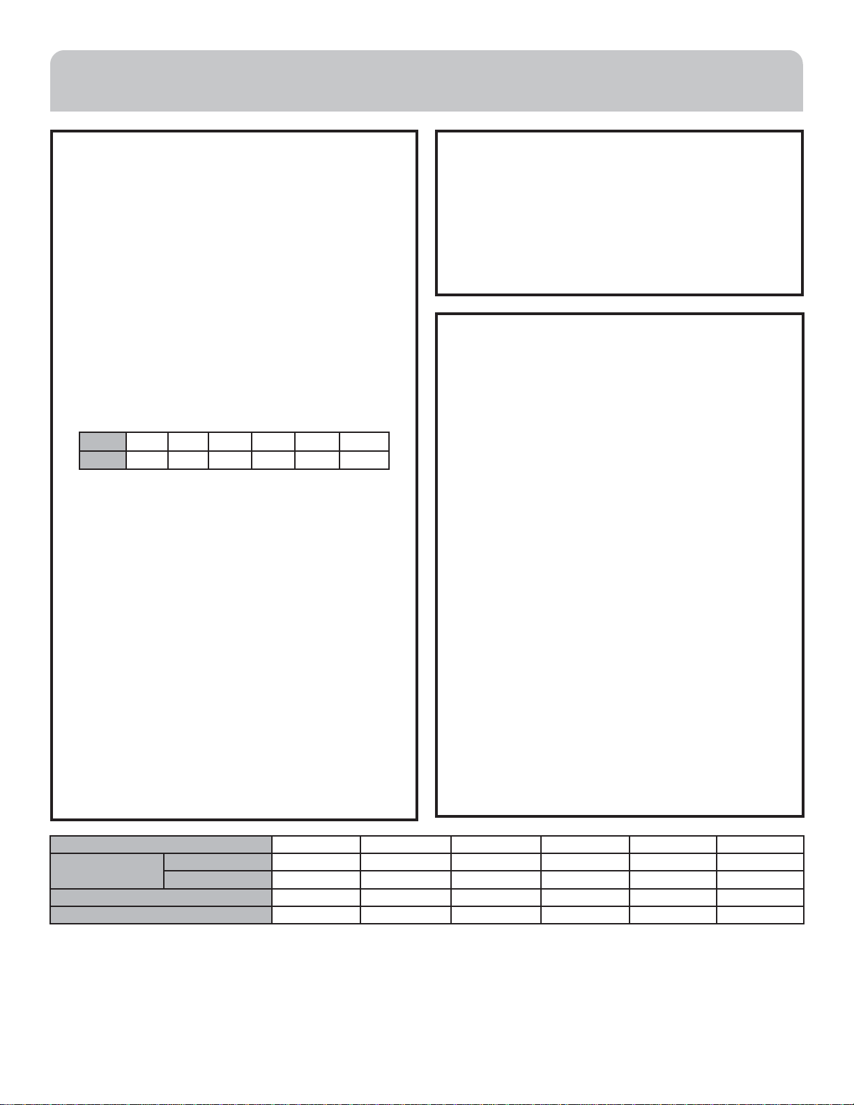
Indoor Fan Time Delay:
For maximum cooling effect, the furnace or air handler
should be equipped with a time delay. Many popular
electronic thermostats have programmable fan delays,
newer furnaces and air handlers include them, and
universal delay kits are readily available on the market.
Model 12K 18K 24K 30K 36K 48K
Delay 115s 90s 90s 90s 100s 65s
Thermostat:
Accurate temperature control and unit operation depends
on proper thermostat selection and location. Refer to
the thermostat manufacturer’s installation instructions
for specific recommendations. Avoid locating on outside
walls, in direct sunlight, in the air path of a supply register,
and in high traffic areas. Thermostats should be centrally
located, close to a return air grille.
System Protection:
A field-supplied liquid line filter-drier must be installed
to remove particulates or moisture that may collect in
the system during field work. Installations without a
filter-drier may void the warranty.
Indoor Unit:
This product is compatible with most major brands of
domestic evaporator coils and air handlers equipped with
a thermostatic expansion valve. Consult AHRI’s directory
of products for certified indoor unit matches.
Unit Location and Mounting
Avoid areas where water, snow, ice, leaves, or other
seasonal debris may fall on or accumulate against the unit.
Do not place the unit in a location where the minimum
clearances cannot be maintained.
For multiple unit installations, the clearance distances
shown below must be maintained.
Required Tools for Installation
• Drill
• 2 1/4” hole saw
• Vacuum pump and oil
• Leak solution or tester
• Tubing cutter
• Pipe reamer
• Razor knife
• Measuring tape
• Level
• Micron gauge
• Dry nitrogen and regulator
• Mini-Split AD-87 Adapter (1/4” to 5/16”)
• Customary HVAC hand tools
• Core removal tool with micron gauge port
• Power and control wiring
• Drain hose (Included)
• Refrigerant scale
• Interior and exterior wall sealant
• 18 Gauge Thermostat Wire
• Brazing materials
Model 12K 18K 24K 30K 36K 48K
Power (outdoor) PHASE 1PHASE 1PHASE 1PHASE 1PHASE 1PHASE 1PHASE
Volt 115 V 208/230V 208/230V 208/230V 208/230V 208/230V
CIRCUIT BREAKER/FUSE (A) 15 15 15 20 25 40
MINIMUM CIRCUIT AMPACITY (A) 11 10 12 15 16 26
Loading ...
Loading ...
Loading ...