Loading ...
Loading ...
Loading ...
16 31-5000485 Rev. 4
INSTALLATION INSTRUCTIONS
Start-up
Operation of the unit is automatic and will provide cooling
depending on the setting of the thermostat.
IMPORTANT
All panels must be installed, the main power turned on,
and the termostat properly connected before operating
the unit.
1. Set thermostat system switch to “Off” position and
fan switch to “Auto” position, Turn the power supply
breaker on.
2. Set the fan switch to “On” and make sure the blower
operates.
3. Return the fan switch to “Auto” and wait until the
blower stops. Set the system switch to “Cool” and
lower thermostat set point to coldest setting. The
compressor, condenser fan, and evaporator blower will
start. Cool air will be supplied after several minutes of
run time.
4. Proceed to the “Fine Tuning” section of these
instructions.
Leak Testing Evacuation, and Charging
The condensing unit is supplied with an R-410A charge
sufficient for most matching evaporator units. Charge
must be added for interconnecting tubing.
R=T X (L-25)ft
R (oz): Additional refrigerant to be charged
L (ft): The length of the liquid pipe
T (oz): The quantity of the charged refrigerant per
additional foot
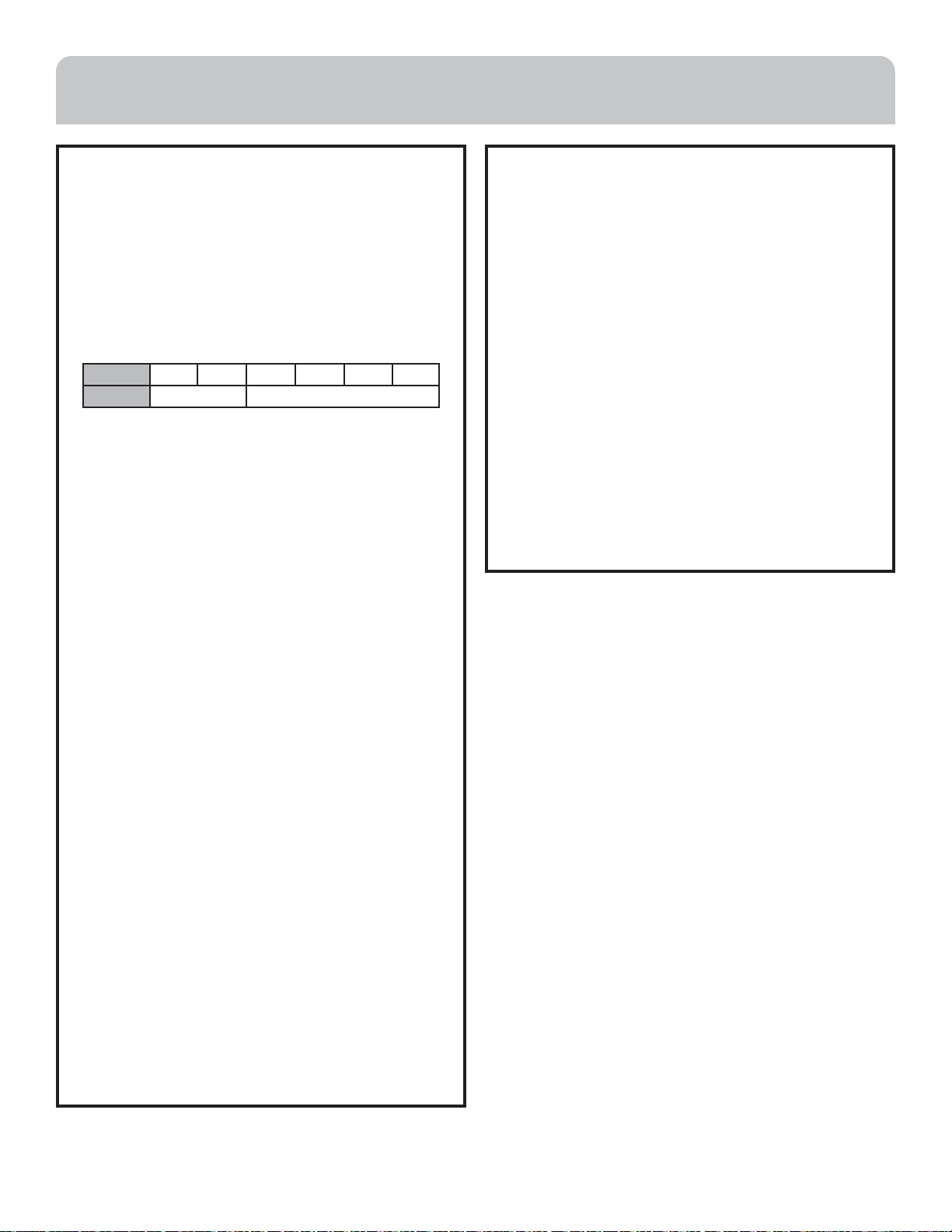
Model 12K 18K 24K 30K 36K 48K
oz/ft 0.16 0.32
The service valves are shipped in the closed position and
should not be opened until final connections, evacuation,
and additional charging are completed.
The recommended procedure for leak test, evacuation,
and charging is outlined below:
1. Complete the final piping connections to the indoor
and outdoor units.
2. Remove the service core from both lines, and connect
a charging manifold to the service ports on the service
valves.
3. Pressurize the lines and evaporator with 500 PSI of
dry nitrogen. Leak check all connections with either
an electronic detector or specialized liquids. Maintain
pressure for at least 30 minutes.
4. Release the nitrogen and connect a vacuum pump to
the manifold center connection. Start the pump and
open the manifold valves.
5. Evacuate to 350 microns or less. Close the manifold
valves and shut off the pump. If the vacuum level
does not rise more than 150 microns in one minute,
the evacuation is considered complete. Otherwise,
the system is indicating either a leak or there is still
moisture present.
6. If a leak is found, repair as necessary and repeat steps 3,
4, and 5. If there are no leaks, continue with Step 5 until
at least 350 microns is attained.
7. Close the manifold valves and disconnect the vacuum
pump. Reinstall the valve cores and add refrigerant
in the amount shown in the charging section of this
manual.
8. Remove the caps from the services valves. Open the
valves to the fully ‘back-seated’ position. Replace
service valve caps and tighten securely.
Loading ...
Loading ...
Loading ...