INSTALLATION INSTRUCTIONS
READ & SAVE THESE INSTRUCTIONS!
TO REGISTER THIS PRODUCT, VISIT WWW.NUTONE.COM
Recess-Mounted
Door Chime
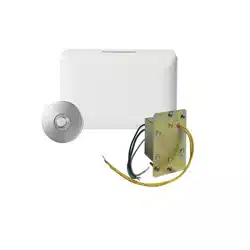
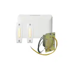
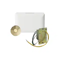
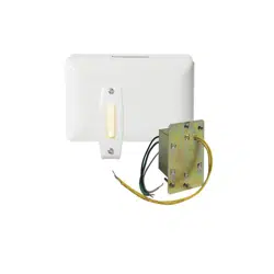
• Your NuTone Door Chime is designed for two-door
operation. For best results, use NuTone Model C905
Transformer.
• Handle the door chime carefully as you would any
precision instrument.
• Comply with local wiring codes when installing the
door chime.
• If upon completion of the installation the chime does not
operate, check your installation against these instructions.
If the chime still does not operate, check the pushbutton(s)
for poor contact or loose connections and wiring for
short circuits.
• If chime plungers should ever become sluggish in their
movement, clean the plungers with a nonflammable
cleaning fluid and wipe dry. CAUTION: NEVER OIL
CHIME PLUNGERS.
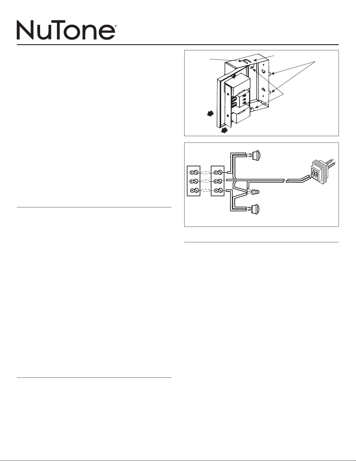
MOUNTING THE FRAME
Refer to Figure 1. The chime mechanism is shipped
mounted in the metal mounting frame. Remove the
cardboard plaster shield and remove the chime mechanism
from the frame by freeing one side and sliding to the side.
NEW CONSTRUCTION
1. Bend or break off the four mounting tabs. Do not bend
tabs inward.
2. Nail the chime mounting frame to a wall stud in the
required location. Position the mounting frame so the
front edge will be flush to the finished wall surface.
3. Complete the wiring connections.
EXISTING CONSTRUCTION
1. In the desired location between wall studs, mark around
the mounting frame and prepare a 4
7
/8” wide by 7” high
cutout.
2. Insert the frame into the cutout until the mounting tabs are
positioned against the wall.
3. Bend the recessed mounting tabs out until they contact the
inside of the wall. The mounting frame should be secured
firmly in position.
4. Complete the wiring connections.
MOUNTING THE DOOR CHIME
1. Install chime to mounting frame after finished wall is
in place.
2. Feed wires through the wiring entrance in the chime’s base
plate and make wire connections to the terminal board.
3. Slide the chime mechanism under the cover mounting
brackets and snap chime into frame.
4. Mount chime cover to mounting brackets by using
supplied screws.
WIRING
• Be certain the power has been disconnected at the main
source before making the connections.
• Comply with local electrical code.
• When stapling wires to studs or joists, do not allow staples
to cut through wire insulation.
1. Mount the transformer to a convenient junction box (attic
location not recommended) or circuit breaker box.
2. Connect house power leads to transformer leads: black to
black, white to white.
3. Run 2-conductor, 18 gauge cable from the transformer
screw terminals and from the pushbutton screw terminals
to the chime location.
4. Refer to Figure 2. Bring wires into the mounting frame.
Connect the transformer and pushbutton wires to the
terminal board on the chime base plate.
FIGURE 1
FIGURE 2
COVER
MOUNTING
BRACKET
SLIDE
CHIME
MECHANISM
FRONT DOOR
PUSHBUTTON
120v AC
WIRING
NUTONE C905
TRANSFORMER -
USE NUTONE MODEL
C907 OR C909 FOR
TWO OR
MORE CHIMES
COMMON
WIRES
REAR DOOR
PUSHBUTTON
TERMINAL
BOARD
CHIME No. 1
TERMINAL
BOARD
CHIME No. 2
18 GAUGE INSULATED
2-CONDUCTOR WIRE
FRONT FRONT
TRANS
TRANS
REAR
REAR
MOUNTING
TABS
RECESS
MOUNTING
TABS
MOUNTING
FRAME

INSTRUCCIONES DE INSTALACIÓN
¡LÉA Y GUARDE ESTAS INSTRUCCIONES¡
PARA REGISTRAR ESTE PRODUCTO, VISITE A WWW.NUTONE.COM
Carillón de Puerta
de Montaje Apartado
• Su Carillón de Puerta NuTone está dise–ado para
operación de dos puertas. Para mejor resultado, use un
Transformador Nutone Modelo C905.
• Maneje el carillón de puerta con cuidado como haría con
cualquier instrumento de precisión.
• Cumpla con todos los códigos locales de alambrado
cuando esté instalando el carillón de puerta
• Si al terminar la instalación el carillón no funciona, verifique
su instalación con estas instrucciones. Si el carillón aun
no funciona, verifique que el(los) botón(es) no tenga
contactos deficientes o conexiones o alambrado sueltos o
cortocircuitos.
• Si los émbolos de carillón llegan a ser lentos en su
movimiento, limpie los émbolos con un líquido limpiador
inflamable y séquelos. ATENCIÓN: NUNCA PONGA
ACEITE EN LOS ÉMBOLOS
MONTAJE DEL MARCO
Vea la Figura 1. El mecanismo del carillón se despacha
montado en el marco de montaje metálico. Remueva la
cubierta de cartón de yeso y remueva el mecanismo del
carillón del marco al soltar un lado y deslizar al otro lado.
NUEVA CONSTRUCCIÓN
1. Doble o rompa las 4 lengüetas de montaje. No doble las
lengüetas hacia adentro.
2. Fije el marco de montaje del carillón a un entramado en el
lugar requerido. Coloque el marco de montaje para que
el lado frontal esté empotrado con la superficie terminada
de la pared.
3. Termine las conexiones de los alambres
CONSTRUCCIÓN EXISTENTE
1. En el lugar deseado entre los entramados de la pared,
marque alrededor del marco de montura y prepare el
corte de hoyo de 4
7
/8” pulgadas (12,4 cm) de ancho por 7
pulgadas (17,8 cm) de alto.
2. Inserte el marco en el hoyo hasta que las lengüetas estén
posicionadas contra la pared.
3. las lengüetas de montaje apartados hacia afuera hasta
que contacten la parte interior de la pared. El marco de
montaje debe estar ajustado firmemente en su posición.
4. Termine las conexiones de los alambres.
ALAMBRADO
• Asegure que la potencia de la fuente de energía esté
desconectada antes de hacer las conexiones.
• Cumpla con el código eléctrico locale.
• Cuando se usen grapas para fijar los alambres a los
entramados o a las vigas, no permita a las grapas penetrar
el aislamiento de los alambres.
1. Monte el transformador en una caja de distribución (no se
recomienda en el ático) o caja del interruptor de circuito.
2. Conecte los alambres de la corriente de la casa: negro a
negro y blanco a blanco.
3. Extienda un alambre de 2 conductores de cable calibre
18 de los terminales de tornillo del transformador y de los
terminales de tornillo del botón al lugar de carillón.
4. Vea la Figura 2. Traiga los alambres dentro del marco
de montaje. Conecte los alambres del transformador y
del botón a la placa terminal en la placa de la base del
carillón.
FIGURA 1
FIGURA 2
SUPPORTE DE
MOMTAJE PARA
LA CUBIERTA
DESLICE
MECANISMO DEL
CARILLÓN
BOTÓN
DE PUERTA DELANTERA
ALAMBRADO
DE 120v CA
TRANSFORMADOR
NUTONE C905
USE EL MODELO
NUTONE C907 O
C909 PARA DOS O
MÁS CARILLONES
ALAMBRES
COMUNES
BOTÓN DE
PUERTA
TRASERA
PLACA
TERMINAL
CARILLÓN No. 1
PLACA
TERMINAL
CARILLÓN No. 2
ALAMBRA DE 2 CONDUCTORES
DE CABLE CALIBRE 18
FRONT FRONT
TRANS
TRANS
REAR
REAR
LENÜETAS
DE
MONTAJE
MONTAJE DEL CARILLÓN DE PUERTA
1. Instale el carillón en el marco de montaje después de que
la pared esté terminada.
2. Meta los alambres por la entrada del alambrado en
la base del carillón y haga las conexiones a la placa
terminal.
3. Deslice el mecanismo del carillón debajo de los soportes
de montaje de la cubierta y meta con chasquido el carillón
en el marco.
4. Monte la cubierta del carillón a los soportes usando los
tornillos provistos.
LENÜETAS DE
MONTAJE
APARTADOS
MARCO DE
MONTAJE

INSTRUCTIONS POUR L’INSTALLATION
LISEZ CES INSTRUCTIONS ET CONSERVES-LES!
POUR ENREGISTRER CE PRODUIT, VISITEZ WWW.NUTONE.COM
Carillon de porte
encastré
• Votre carillon de porte encastré est conçu pour un
fonctionne,ent à deux portes. Pour de meilleurs résultats,
utilisez le modèle de transformateur C905.
• Il faut manipuler le carillon de porte avec beaucoup de soin
comme avec n’importe quel instrument de précision.
• Lorsque vous installez le carillon, veuillez vous conformer
aux normes locales de câblage.
• Si aprés l’installation votre carillon ne fonctionne pas,
référez-vous aux directives. Contrôles, dans ce cas, si le
bouton poussoir(s) a un mauvais contact, si les connexions
sont lâches, et vérifiez s’il n’y a pas de court-circuit au
câblage.
• Si le mouvement des poussoirs du carillon devient
médiocre, nettoyez-les avec un liquide non
flammable et séchez-les. PRUDENCE: NE HUILEZ
JAMAIS LES POUSSOIRS.
MONTAGE DU CHÂSSIS
Référez-vous à la Figure 1. Le mécanisme du carillon est
monté dans un châssis en métal. Enlevez l’écran de plâtre en
carton et le mécanisme du carillon de son châssis en libérant
un côté et en glissant l’autre côté.
NOUVELLES CONSTRUCTION
1. Pliez pu brisez les quatre onglets de montage. Ne pliez
pas les onglets vers l’intérieur.
2. Clouez le châssis de montage du carillon à un poteau
mural à l’endroit requis. Placez le châssis de montage
pour que la partie antérieure soit bein encastrée avec la
surface finie du mur.
3. Complétez les connexions de câblage.
CONSTRUCTION EXISTANTE
1. À l’endroit désiré entre les poteaux muraux, marquez le
tour du châssis de montage et préparez une découpe de
4
7
/8” large par 7” de haut.
2. Insérez le châssis dans la forme obtenue par le
découpage jusqu’à ce que les onglets de montage soient
placés contre le mur.
3. Pliez les onglets de montage encastrés vers l’extérieur
jusqu’à ce qu’ils entrent en contact avec l’intérieur du mur.
Le châssis de montage doit être bein calé en place.
4. Complétez les connexions de câblage.
MONTAGE DE LA PORTE DU CARILLON
1. Installez le carillon au châssis de montage après que le
mur fini est en place.
2. Faites passer les fils à travers l’entrée du câblage dans
la plaque de base du carillon et faites des liasions vers la
plaque à bornes.
3. Glissen le mécanisme du carillon en dessous des plaques
de fixation du couvercle et enclenchez le carillon dans le
châssis.
CÂBLAGE
• Assurez-vous que l’alimentation a été débranchée à la
source principale avante de faire les connexions.
• Conformez-vous au code électrique local.
• Lorsque vous agrafez les fils aux poteaux ou aux poutrelles,
ne permettez pas aux agrafes de couper l’isolement de fils.
1. Montez le transformateur à une boîte à bornes convenable
(l’emplacement dans un grenier n’est pas recommandé)
ou un boîter de disjoncteur.
2. Branchez les fils de sortie d’alimentation de la maison aux
fils de sortie du transformateur: noir à noir, blanc à blanc.
3. Se branche sur un cnducteur isolé calibre 18, à deux
âmes, des bornes à vis du transformateur et des bornes à
vis du bouton poussoir à l’emplacement du carillon.
4. Se réfère à la Figure 2. Faites passer les fils dans le
châssis de montage. Branchez les fils du transformateur et
du bouton poussoir à la plaque à borne dans la plaque de
base du carillon.
FIGURE 1
FIGURE 2
PLAQUE DE
FIXATION DU
COUVERCLE
MÉCANISME DU
GLISSEMENT DU
CARILLON
BOUTON DE PORT
D AVANT
CONEXION
DE 120v CA
NUTONE C905
TRANSFORMATEUR
UTILISEZ MODÈLE
NUTONE C907 OU
C909 POUR DEUX
CARILLONS OU PLUS
FILS
COMMUNS
BOUTON
PORTE
ARRIÈRE
TABLEAU
BORNE
CARILLON NO. 1
TABLEAU
BORNE
CARILLON NO. 2
FIL DE 2 CONDUCTEURS ISOLE
DE 18 JAUGE
FRONT FRONT
TRANS
TRANS
REAR
REAR
ONGLETS
DE
MONTAGE
CHÂSSIS
DE
MONTAGE
4. Assemblez le couvercle du carillon aux plaques de fixation
du couvercle en utilisant les vis spéciales.
ONGLETS DE
MONTAGE
ENCASTRÉAS

99526158B
One Year Limited Warranty
WARRANTY OWNER: Broan-NuTone warrants to the original consumer purchaser of its products that such products will be free from defects in materials or
workmanship for a period of one (1) year from the date of original purchase. THERE ARE NO OTHER WARRANTIES, EXPRESS OR IMPLIED, INCLUDING,
BUT NOT LIMITED TO, IMPLIED WARRANTIES OF MERCHANTABILITY OR FITNESS FOR A PARTICULAR PURPOSE.
During this one year period, Broan-NuTone will, at its option, repair or replace, without charge, any product or part which is found to be defective under
normal use and service. THIS WARRANTY DOES NOT EXTEND TO FLUORESCENT LAMP STARTERS OR TUBES, FILTERS, DUCT, ROOF CAPS,
WALL CAPS AND OTHER ACCESSORIES FOR DUCTING. This warranty does not cover (a) normal maintenance and service or (b) any products or parts
which have been subject to misuse, negligence, accident, improper maintenance or repair (other than by Broan-NuTone), faulty installation or installation
contrary to recommended installation instructions.
The duration of any implied warranty is limited to the one year period as specified for the express warranty. Some states do not allow limitation on how long an
implied warranty lasts, so the above limitation may not apply to you.
BROAN-NUTONE’S OBLIGATION TO REPAIR OR REPLACE, AT BROAN-NUTONE’S OPTION, SHALL BE THE PURCHASER’S SOLE AND
EXCLUSIVE REMEDY UNDER THIS WARRANTY. BROAN-NUTONE SHALL NOT BE LIABLE FOR INCIDENTAL, CONSEQUENTIAL OR SPECIAL
DAMAGES ARISING OUT OF OR IN CONNECTION WITH PRODUCT USE OR PERFORMANCE. Some states do not allow the exclusion or limitation of
incidental or consequential damages, so the above limitation or exclusion may not apply to you. This warranty gives you specific legal rights, and you may also
have other rights, which vary from state to state. This warranty supersedes all prior warranties.
WARRANTY SERVICE: To qualify for warranty service, you must (a) notify Broan-NuTone at the address or telephone number below, (b) give the
model number and part identification and (c) describe the nature of any defect in the product or part. At the time of requesting warranty service,
you must present evidence of the original purchase date.
Date of Installation
Builder or Installer
Model No. and Product Description
IF YOU NEED ASSISTANCE OR SERVICE - CONTACT:
Broan-NuTone LLC Hartford, Wisconsin www.nutone.com 888-336-3948
Broan-NuTone Canada Mississauga, Ontario www.nutone.ca 877-896-1119
Rev. 08/2007
Garantie limitée d’un an
GARANTIE DU PROPRIÉTAIRE: Broan-NuTone garantie à l’acheteur original de ses produits que ces derniers seront exmpts de tout défaut de matériaux
et de fabrication pour une période d’un (1) an à compter de la date d’acha. AUCUNE AUTRE GARANTIE, IMPLICITE OU EXPRESSE, N’EST DONNÉE, Y
COMPRIS, MAIS SANS S’Y LIMITER, GARANTIE DE MARCHANDIBILITÉ OU D’ADAPTATION À UN USAGE PARTICULIER.
Pendant cette période d’un an, Broan-NuTone procédera au remplacement ou à la réparation sans aucuns frais, mais à sa propre discrétion, de tout produit
ou pièce jugé défectueux dans le cadre d’une utilisation normale. CETTE GARANATIE NE VISE PAS LES DISPOSITIFS D’AMORCAGE NI LES TUBES DES
LUMINAIRES FLUORESCENTS. Cette garantie ne couvre pas (a) l’entretien et le service courants ni (b) les produits et les pièces ayant fait l’objet du’n usage
abusif, de négligence, d’un accident, d’un entretien ou d’une réparation non appropriée (par du personnel non autorisé par Broan-NuTone) d’une mauvaise
installation ou d’une installation non conforme aux directives d’installation fournies.
La durée de toute garantie implicite est limitée à la période de deux ans précisée pour la garantie expresse. Certains états ne reconnaissent pas les restrictions
relatives à la durée des garanties implicites; il se pourrait donc que cette restriction ne s’applique pas dans votre cas.
LE REMPLACEMENT OU LA RÉPARATION PAR BROAN-NUTONE, À SA PROPRE DISCRÉTION, DE TOUT PRODUIT OU PIÈCE DÉFECTUEUX
CONSTITUE LE SEUL REMÈDE DE L’ACHETEUR EN VERTU DE CETTE GARANTIE. BROAN-NUTONE NE PEUT ÊTRE TENUE RESPONSABLE
DES DOMMAGES INDIRECTS, CONSÉCUTIFS OU SPÉCIAUX ATTRIBUABLES À UTILISATION OU AU RENDEMENT DU PRODUIT. Certains états
ne reconnaissent pas les restrictions ni les exclusions relatives aux dommages indirects, consécutifs ou spéciaux; il se pourrait donc que cette restriction ne
s’applique pas dans votre cas. La présente garantie vous accorde des droits spécifiques, mais vous pourriez aussi avoir d’autres droits en fonction de l’état
dans lequel vous résidez. Cette garantie remplace toute autre garantie donnée précédement.
SERVICE SOUS GRANTIE: Pour être admissible au service sous garantie, vous devez (a) aviser Broan-NuTone, à l’adresse ou au numéro de
téléphone ci-dessous, (b) fournir le numéro du modèle et la description de la pièce et (c) décrire la nature défaut de la pièce ou du produit. Au
moment de la demande de service sous garantie, vous devez fournir une preuve de la date d’achat originale.
Date d’installation
Entrepeneur ou installateur
N° de modèle et description du produit
POUR OBTENIR DE L’ASSITANCE OU DU SERVICE - CONTACTEZ:
Broan-NuTone LLC Hartford, Wisconsin www.nutone.com 888-336-3948
Broan-NuTone Canada Mississauga, Ontario www.nutone.ca 877-896-1119
Rev. 08/2007
Garantia Limitada de un Año
GARANTÍA DEL PROPIETARIO: Broan-NuTone garantiza al comprador consumidor original de sus productos, por el período de un (1) año desde la
fecha original de compra, que tales productos están libres de defectos en material y mano de obra. NO HAY OTRAS GRANTÍAS, EXPRESADOS O
SOBREENTENDIDAS, INCLUYENDO, PERO NO LIMITADAS A, GRANTÍAS NO EXPRESADAS DE MERCHNTIBILIDAD O ADAPTABLES A UN
PROPÓSITO EN PARTICULAR.
Durante este período de un año, Broan-NuTone reparará o reemplazará a su opción y sin costo, cualquier producto o parte que se encuentre defectuoso
bajo condiciones normales de uso y servicio. ESTA GARANTÍA NO CUBRE A LOS ARRANCADORES PARA LÁMPARAS FLUORESCENTES O A LOS
TUBOS FLUORESCENTES, FILTROS, DUCTOS, TAPAS DE TECHO, TAPAS DE PARED Y OTROS ACCESORIOS PARA CANALIZACIÓN. Esta granatía
no cubre (a) Mantenimiento y servicios normales (b) Productos o partes sujetos al mal uso, negligencia, accidente, mantenimiento inadecuado o reparaciones
(port otros ajenos a Broan-NuTone), instalación defectusoa o a una instalación contraria a las instrucciones de instalación recomendadas.
La duración de cualquier garantia no expresada está limitada a un periodo de un año según se especifica en la garantia expresada. Algunos estados no
permiten limitación en cuanto a la duración de una grantia no expresada, por lo que la limitación arriba indicada puede que no se apliqué a Ud.
LA OBLIGACIÓN DE BROAN-NUTONE DE REPARAR O REEMPLAZAR A SU OPCIÓN, SERÁ EL ÚNICO Y EXCLUSIVO RECURSO QUE TENDRÁ
EL COMPRADOR BAJO ESTA GARANTÍA. BROAN-NUTONE NO SERÁ RESPONSABLE POR DAÑOS INCIDENTALES, CONSECUENTES O
ESPECIALES QUE RESULTEN A CONSECUENCIA O SEAN INDEPENDIENTE DEL USO O DESEMPEÑO DEL PRODUCTO. Algunos estados no
permiten la exclusión o limitación de daños incidentals o consecuentes, de modo que la limitación o exclusión arriba indicada pueda que no se aplique a Ud.
Esta garantia le proporciona derechos legales especificos, y Ud.puede tener otros derechos, los cuales varían de estado a estado. Esta garantias reemplaza
a todas las garantías anteriores..
SERVICO DE GARANTÍA: Para tener derecho al servicio de garantía, Ud. debe (a) Notificar a Broan-NuTone a la dirección o el número de teléfono
abajo, (b) indicar el número de modelo y la identifación de la party y (c) describir la naturaleza de cualquier defecto en la producto o parte. Al
momento de solicitor el servicio por la garantía, Ud. debe presentar la evidencia de la fecha original de compra.
Fecha de la instalación
Constructor o instalador
Número de modelo y descripción del producto
SI NECESITA ASISTENCIA O SERIVIVIO - CONTACTO:
Broan-NuTone LLC Hartford, Wisconsin www.nutone.com 888-336-3948
Broan-NuTone Canada Mississauga, Ontario www.nutone.ca 877-896-1119
Rev. 08/2007