Store this manual for future reference
1030-110-01
®
Non-Programmable Thermostats
User Manual
Read all instructions before proceeding.
ECONOMY
SERIES
1030
1 Heat / 1 Cool Conventional
or Heat Pump
Up to 2 Heat / 1 Cool
Conventional or Heat Pump
1230
This manual covers the following thermostat models:
Contents
1 About Your Thermostat
Quick Reference - Thermostat and Display ............... 3
2 User Settings
User Settings ............................................................5
Table of User Settings ...............................................6
Resetting Service Reminders ....................................6
Service Reminders ................................................... 6
Resetting Thermostat ............................................... 6
3 Operating Your Thermostat
Setting the System Control Mode ............................. 7
Setting the Fan Control Mode ................................... 7
Temperature Adjustment .......................................... 8
System Status and Maintenance Indicators .............. 8
4 Additional Operation Features
Compressor Protection ........................................ 10
5 Thermostat Maintenance
Battery Replacement ........................................... 11
Thermostat Cleaning ........................................... 11
User Manual 2
3 User Manual
1
About Your Thermostat
1
3
2
4
5
6
7
10
9
8
User Manual 4
SYSTEM Switch ..................... Selects the system you want to control
FAN Switch ............................ Selects the system fan mode
Up / Down Arrow Buttons ..... Increases or decreases settings
MENU Button ......................... Used to access thermostat User setting mode
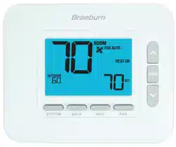
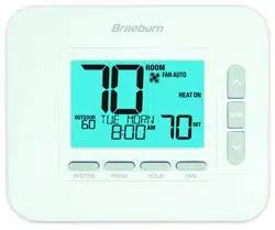
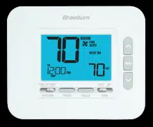
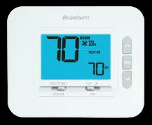
Room Temperature .............. Displays the current room temperature
Set Temperature .................. Displays the current setpoint temperature
System Mode .......................Displays the system mode and current system status
Fan Status Indicator ............ Indicates that the system fan is running
Fan Mode Indicator ..............Indicates the current system fan mode
Low Battery Indicator ......... Indicates when the batteries need to be replaced
Battery Compartment .......... Located on the back side of thermostat
1
2
3
4
Thermostat and Display
5
6
7
8
9
10
5 User Manual
2
User Settings
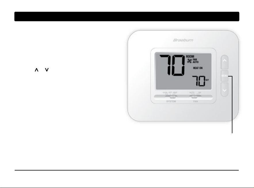
User Settings allow you set and customize
various thermostat features.
To access the User Settings, press and release the
MENU button to display the first User Setting.
Press the or buttons to change the value for the
displayed User Setting. After your desired setting is
displayed, press MENU to advance to the next
User Setting.
You will exit the user settings after the last setting.
MENU
User Manual 6
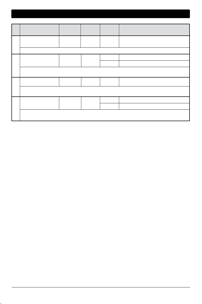
Table of User Settings
No.
User Setting
Displayed
Default
Available
Description of
Setting Settings Available Settings
1 Reset SERVICE CLR N0
FILTER Message
[Only appears if the service filter time interval has expired] If a service filter time interval was selected in setting 2,
the thermostat will display a SERVICE FILTER message once that time interval is reached. Select NO to keep the message
displayed or select Y (YES) to clear the message and reset the timer.
.
2 Service Filter Timer
SERVICE OFF
FILTER
Select the number of days before receiving a reminder to change your system filter (if equipped). When the timer interval has
expired, the thermostat will display the message SERVICE FILTER. To reset this reminder, see setting 1. To disable, select OFF.
3 User Reset CLR NO
Selecting (Y) YES will reset all user settings.
N0 Select to keep message displayed
Y Select to remove message and reset timer
OFF Service filter timer is disabled
30, 60, 90,
Select number of days for service filter timer
120, 180, 365
NO Reset disabled - no changes made
Y
Reset enabled - resets thermostat
7 User Manual
3
Operating Your Thermostat
Setting the SYSTEM Control Mode
The System Control has 4 modes of operation – COOL, OFF, HEAT, and EMER (1230 only). The mode can be
selected by moving the SYSTEM switch to the appropriate mode.
COOL Only your cooling system will operate.
OFF Heating and cooling systems are off.
HEAT Only your heating system will operate
EMER Operates a backup heat source (Emergency Heat) for
heat pump systems only (model 1230 only).
Setting the FAN Control Mode
The Fan Control has 2 modes of operation – AUTO and ON. The mode can be selected by moving the FAN
switch to the appropriate mode.
AUTO The system fan will run only when your heating or cooling system is running.
ON The system fan stays on.
User Manual 8
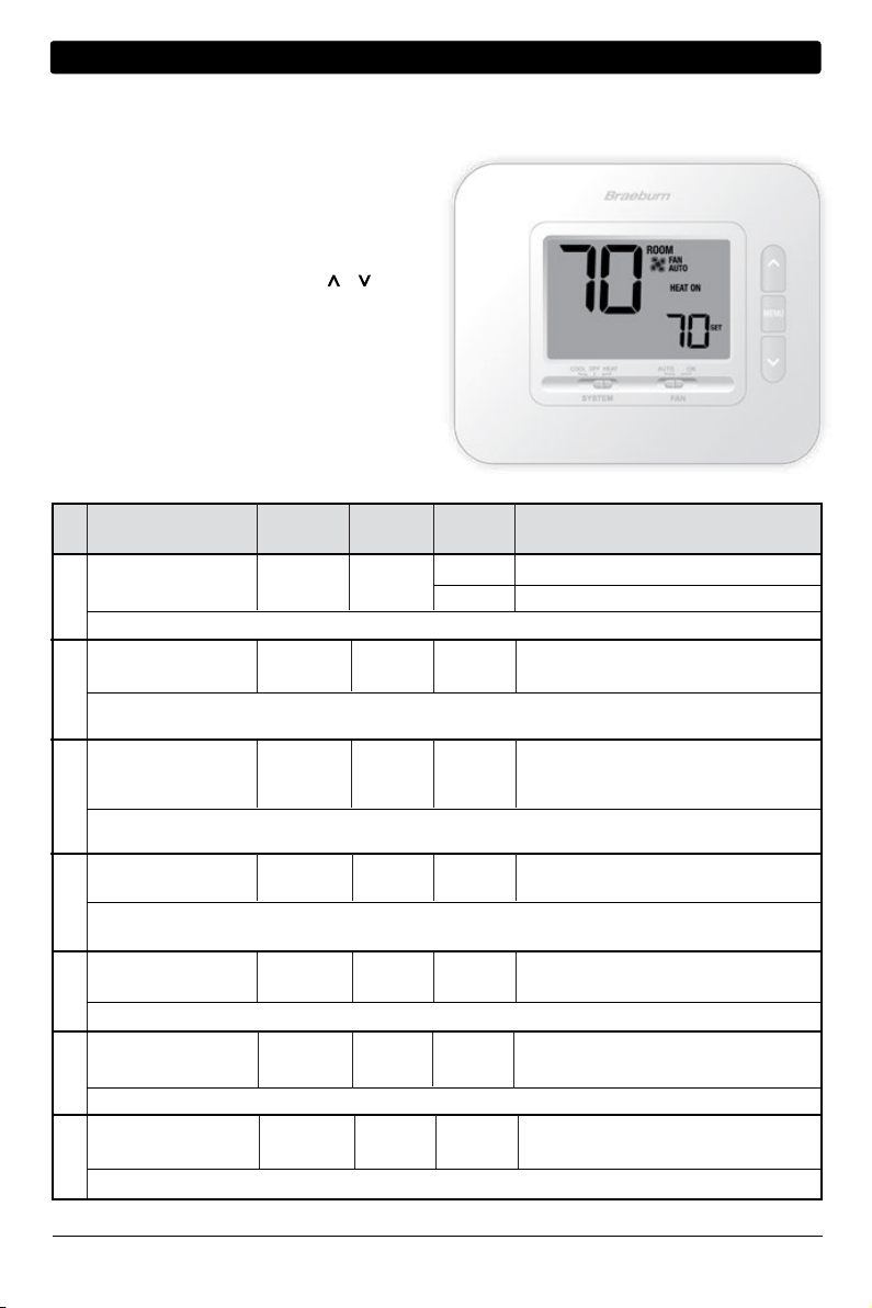
Temperature Adjustment
Press or to adjust the current set temperature.
System Status and Maintenance Indicators
Status indicators are messages or symbols that appear in the display to let you know what function your system
is currently performing. They are also used to inform you of various service and maintenance functions.
HEAT ON The heating system is running.
COOL ON The cooling system is running.
HEAT ON AUX The auxiliary stage of heating is running
(model 1230 only).
EMERGENCY
The emergency heating system is
HEAT ON running (model 1230 only).
Indicates that the system fan is running.
SERVICE A user selectable filter service reminder for changing
FILTER the filter has been triggered. To set or reset this
reminder, see User Settings in section 2.
AUTO
FAN
ROOM
SET
HEAT ON
AUTO
FAN
ROOM
SET
HEAT
SERVICE
FILTER
9 User Manual
System Status and Maintenance Indicators (continued)
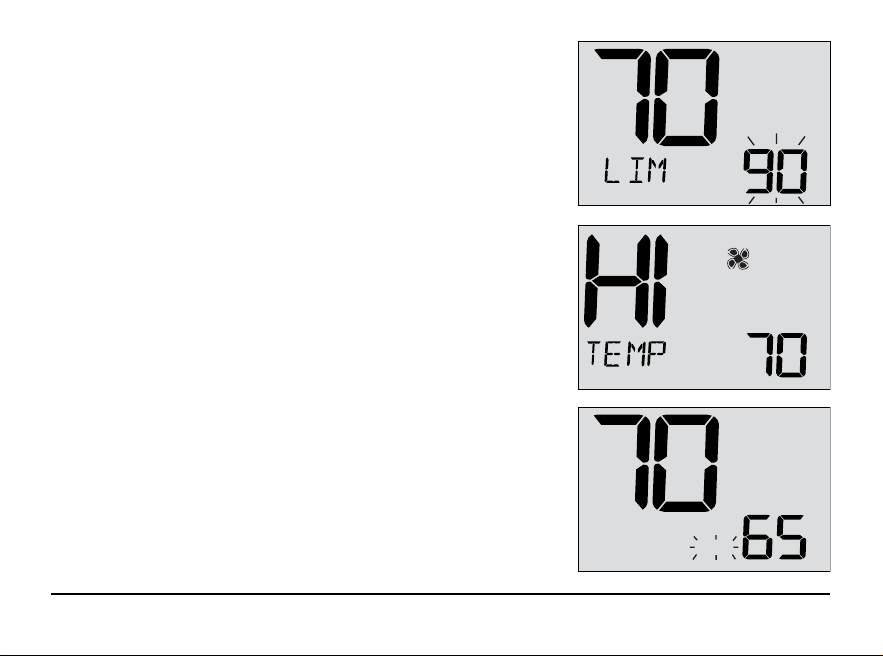
LIM Setpoint temperature has reached its
upper or lower limit maximum.
HI TEMP Room temperature has risen above the
display range. Cooling will still operate to
help lower temperature.
LO TEMP Room temperature has fallen below the
display range. Heat will still operate to help
raise temperature.
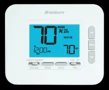
CHECK Indicates that there is a potential problem with
your system. Contact a local service technician.
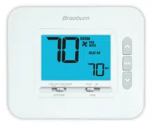
AUTO
FAN
COOL
ROOM
SET
ROOM
SET
FAN
AUTO
COOL ON
AUTO
FAN
ROOM
SET
HEAT
CHECK
User Manual 10
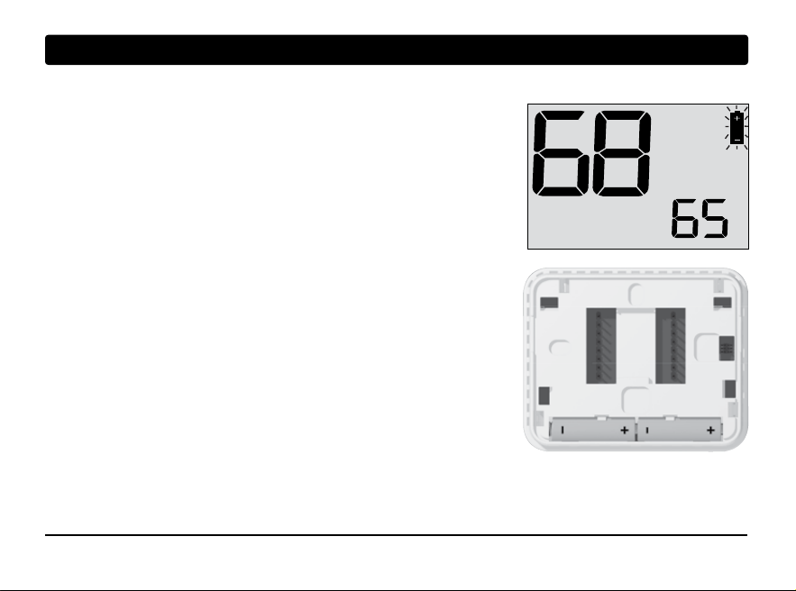
System Status and Maintenance Indicators (continued)
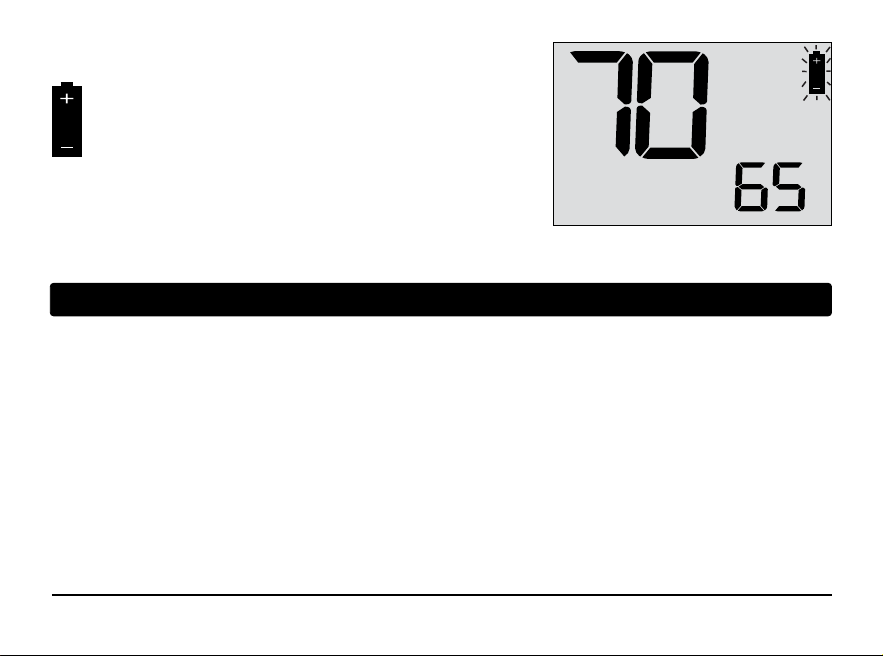
If batteries are installed and they become
low, the battery symbol appears in the display.
When the batteries become critically low, the
battery symbol will flash (see “Changing the
Batteries” in section 5).
AUTO
FAN
ROOM
SET
HEAT
4
Additional Operating Features
Compressor Protection
This thermostat includes an automatic compressor protection delay to avoid potential damage to your system
from short cycling. This feature activates a short delay after turning off the system compressor.
11 User Manual
5
Thermostat Maintenance
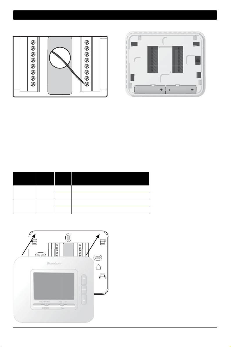
Changing the Batteries
Depending on your installation, this thermostat may be equipped with
two (2) “AA” type alkaline batteries.
If batteries are installed and they become low, the battery symbol appears
in the display. When the batteries become critically low, the battery symbol
will flash.
To change your batteries:
1. Remove thermostat body by gently pulling it from base.
2. Remove old batteries and replace with new batteries.
3. Make sure to correctly position the (+) and (-) symbols.
4. Gently push thermostat body back onto base.
NOTE: We recommend replacing the thermostat batteries
annually or if the thermostat will be unattended for
an extended period of time.
Thermostat Cleaning
Never spray any liquid directly on the thermostat. Spray
your
cleaning liquid on a soft cloth and then proceed to
clean the screen
with the damp cloth. Only use water or
household glass cleaner. Never use any abrasive cleansers
to clean your thermostat.
AUTO
FAN
ROOM
SET
HEAT

For more information, visit www.braeburnonline.com
Limited Warranty
When installed by a professional contractor, this product is backed by a 5 year limited warranty. Limitations apply.
For limitations, terms and conditions, you may obtain a full copy of this warranty.
• Visit us online: www.braeburnonline.com/warranty
• Phone us: 866.268.5599
• Or write us: Braeburn Systems LLC
2215 Cornell Avenue
Montgomery, IL 60538
Braeburn Systems LLC
2215 Cornell Avenue • Montgomery, IL 60538
Technical Assistance: www.braeburnonline.com
Call us toll-free: 866-268-5599 (U.S.)
630-844-1968 (Outside the U.S.)
©2022 Braeburn Systems LLC • All Rights Reserved.
1030-110-01