Loading ...
Loading ...
Loading ...
20
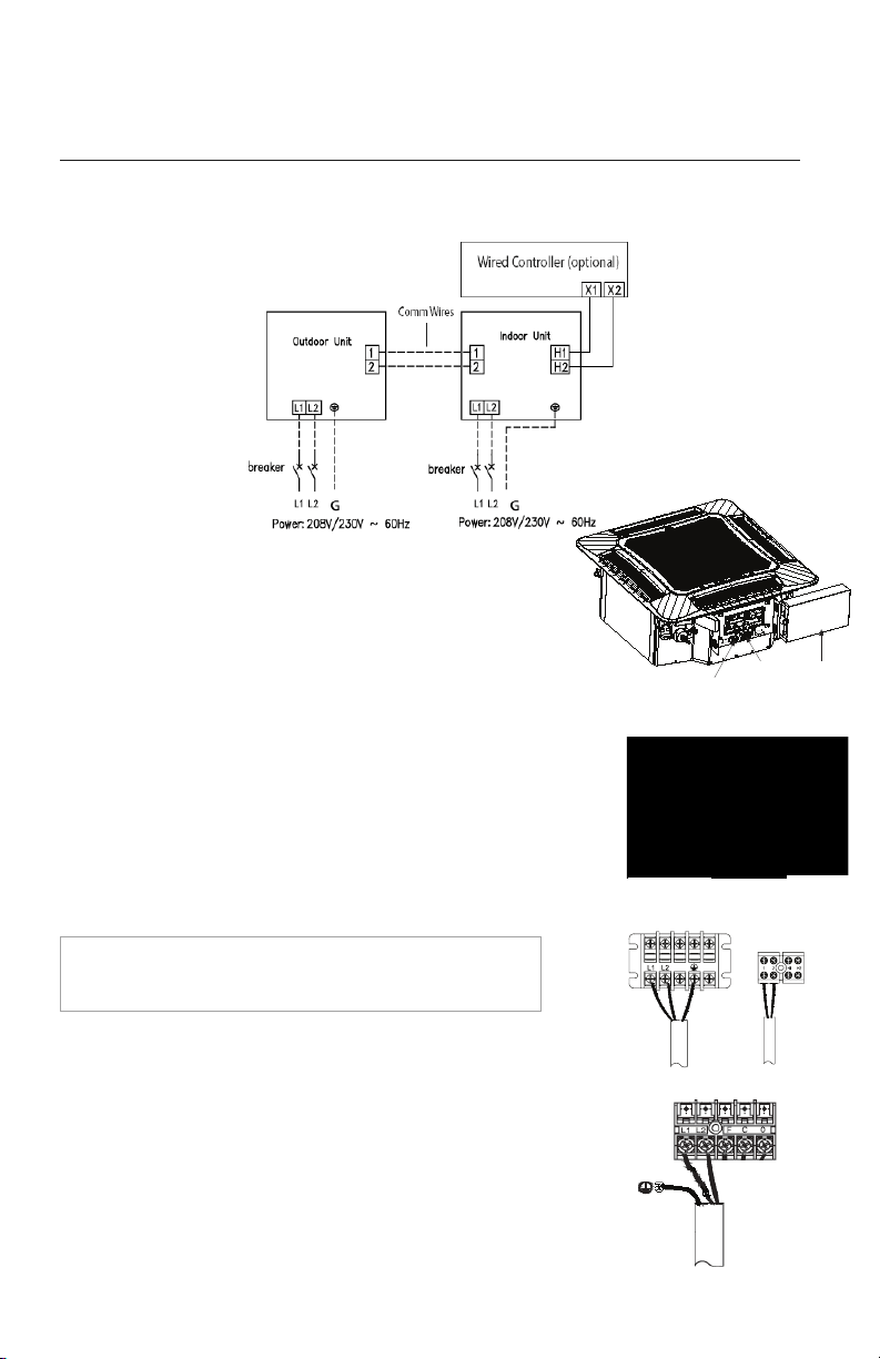
Electric Wiring Between Indoor Unit and Outdoor Unit
Indoor Unit Electrical Wiring
Locate and remove the electrical box cover to access wire terminals.
Single-phase units
(18K~48K)
POWER AND WIRING INSTALLATION
Indoor Communication Wiring
The recommended communication cable size is a minimum 18/2
AWG stranded bare copper conductors THHN 300V unshielded
wire. Use shielded cable if installation is in close proximity of RF
and EMI transmitting devices. Locate wire terminals #1 and #2.
Connect communication cable from outdoor unit to terminals #1
and #2. Secure cable inside wire clamp/strain relief. Verify cable
is secure, not loose and no external force on wires affects the
connections at the terminals.
Indoor Unit Power Wiring
Locate wire terminals L1 and L2. Connect main electrical power
outdoor unit to terminals L1 and L2. Connect ground wire to
grounding screw. Secure electrical wires inside wire clamp/strain
relief. Verify wires are secure, not loose and no external force on
wires affects the connections at the terminals.
NOTE: Record wire colors and terminal references for use
with Outdoor Unit wire connections.
Typical Wiring Diagram
48K
Communication
terminal board
Communication
terminal board
Power supply
terminal board
Electric
box cover
Electric
box cover
18K~42K
Loading ...
Loading ...
Loading ...