U-MATCH SERIES DC INVERTER AIR
CONDITIONERS SERVICE MANUAL
T3/R410A/60Hz
(GC201605 - І )

CONTENTS
PRODUCT .............................................................................................................................................. 2
1 MODELS LIST...............................................................................................................................................2
1.1 Outdoor Unit ........................................................................................................................................................... 2
1.2 Indoor Unit .............................................................................................................................................................. 3
2 NOMENCLATURE ........................................................................................................................................4
2.1 Outdoor Unit ........................................................................................................................................................... 4
2.2 Indoor Unit .............................................................................................................................................................. 4
3 PRODUCT DATA ..........................................................................................................................................5
3.1 Product Data of Indoor Unit ................................................................................................................................. 5
3.2 Operation Range ................................................................................................................................................. 11
3.3 Electrical Data ...................................................................................................................................................... 11
4 PIPING DIAGRAM ..................................................................................................................................... 12
CONTROL ............................................................................................................................................ 14
1 OPERATION FLOWCHART .................................................................................................................... 14
1.1 Cooling/Dry Operation ........................................................................................................................................ 14
1.2 Heating Operation ............................................................................................................................................... 15
2 WIRELESS REMOTE CONTROLLER ................................................................................................... 16
3 WIRED CONTROLLER ............................................................................................................................ 18
3.1 Display View ......................................................................................................................................................... 18
3.2 Operation View .................................................................................................................................................... 20
4 OPERATION INSTRUCTION OF SPECIAL FUNCTIONS .................................................................. 23
4.1 Setting of Filter Clean Reminder Function....................................................................................................... 23
4.2 Low Temperature Drying Function .................................................................................................................... 25
4.3 Lock Function ....................................................................................................................................................... 25
4.4 Memory Function ................................................................................................................................................. 26
4.5 Door Control Function/Human Sensitive Function ......................................................................................... 26
4.6 Switch between Fahrenheit and Centigrade ................................................................................................... 26
4.7 Enquiry of Ambient Temperature ....................................................................................................................... 26
4.8 Enquiry of Historical Malfunction ....................................................................................................................... 27
4.9 Debugging Function ............................................................................................................................................ 27
5 INSTALLATION OF WIRED CONTROLLER ......................................................................................... 31
5.1 Standard Accessories ......................................................................................................................................... 31
5.2 Installation Position and Requirement .............................................................................................................. 31
5.3 Installation of Wired Controller .......................................................................................................................... 32
5.4 Removal of Wired Controller.............................................................................................................................. 32
6 TROUBLESHOOTING .............................................................................................................................. 33

7 CENTRALIZED CONTROLLER .............................................................................................................. 34
7.1 Smart Zone Controller ........................................................................................................................................ 34
7.2 Additional Special Functions .............................................................................................................................. 38
INSTALLATION .................................................................................................................................... 53
1 INDOOR UNIT INSTALLATION ............................................................................................................... 53
1.1 Installation of Duct Type ..................................................................................................................................... 53
1.2 Installation of Floor Ceiling Type ....................................................................................................................... 62
1.3 Installation of Cassette Type.............................................................................................................................. 69
2 OUTDOOR UNIT INSTALLATION .......................................................................................................... 79
2.1 Before Installation ................................................................................................................................................ 79
2.2 Installation Site .................................................................................................................................................... 79
2.3 Caution for Installation ........................................................................................................................................ 80
2.4 Dimension Data ................................................................................................................................................... 80
3 REFRIGERATION PIPING WORK ......................................................................................................... 81
3.1 Refrigeration Piping Work Procedures and Caution in Connecting ............................................................. 81
3.2 Specification of Connection Pipe ...................................................................................................................... 86
4 ELECTRIC WIRING WORK ..................................................................................................................... 86
4.1 Wiring Precautions .............................................................................................................................................. 86
4.2 Electrical Wiring ................................................................................................................................................... 87
MAINTENANCE .................................................................................................................................. 94
1 TROUBLE TABLE ...................................................................................................................................... 94
1.1 Main Control Malfunction ................................................................................................................................... 94
1.2 Description of Drive Malfunction ....................................................................................................................... 97
2 FLOW CHART OF TROUBLESHOOTING ............................................................................................ 98
2.1 Troubleshooting Flow Chart of Main Control Malfunction ............................................................................. 98
2.2 Troubleshooting Flow Chart of Drive Malfunction ......................................................................................... 105
2.3 Interface .............................................................................................................................................................. 110
2.4 IPM, PFC Testing Method ................................................................................................................................ 116
3 WIRING DIADRAM .................................................................................................................................. 117
3.1 Outdoor unit ....................................................................................................................................................... 117
3.2 Indoor unit ........................................................................................................................................................... 120
4 DISASSEMBLY AND ASSEMBLY PROCEDURE OF MAIN PARTS .............................................. 124
4.1 Outdoor Unit ....................................................................................................................................................... 124
4.2 Indoor Unit .......................................................................................................................................................... 128
5 EXPLODED VIEWS AND SPARE PART LIST .................................................................................... 142
5.1 Outdoor Unit ....................................................................................................................................................... 142
5.2 Indoor Unit .......................................................................................................................................................... 154

U-Match Series DC Inverter Service Manual
1
PRODUCT
U-Match Series DC Inverter Service Manual
2
PRODUCT
1 MODELS LIST
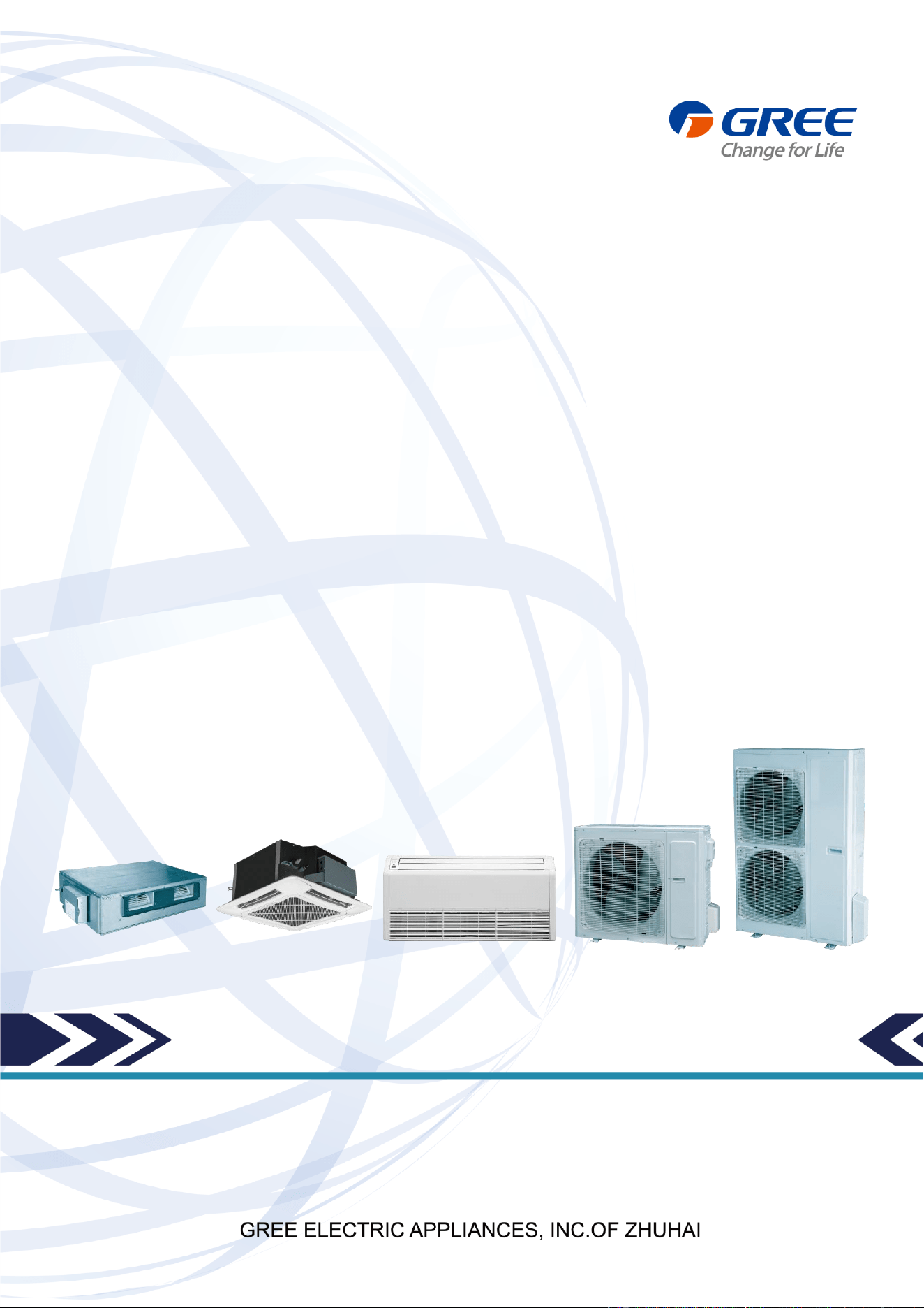
1.1 Outdoor Unit
Model Name
Product Code
Power Supply
(V, Ph, Hz)
Appearance
UMAT18HP230V1AO
CF090W0751
208/230V~60Hz
UMAT24HP230V1AO
CF090W0761
208/230V~60Hz
UMAT30HP230V1AO
CF090W0830
208/230V~60Hz
UMAT36HP230V1AO
CF090W0771
208/230V~60Hz
UMAT42HP230V1AO
CF090W0840
208/230V~60Hz
UMAT48HP230V1AO
CF090W0781
208/230V~60Hz
U-Match Series DC Inverter Service Manual
3
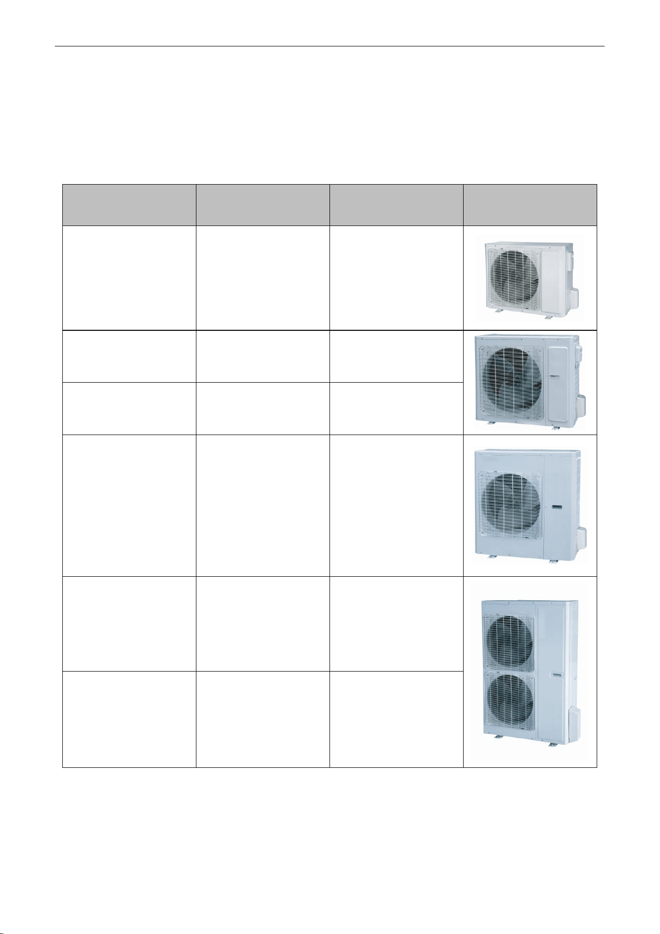
1.2 Indoor Unit
Type
Model Name
Product Code
Nominal Capacity
Cooling/Heating
(Btu/h)
Power Supply
(V, Ph, Hz)
Appearance
Duct
Type
UMAT18HP230V1AD
CF060N0512
CF060N0513
17100/18800
208/230V~60Hz
UMAT24HP230V1AD
CF060N0522
CF060N0523
23800/27200
208/230V~60Hz
UMAT30HP230V1AD
CF060N0580
CF060N0590
28200/31200
208/230V~60Hz
UMAT36HP230V1AD
CF060N0532
CF060N0533
34000/41000
208/230V~60Hz
UMAT42HP230V1AD
CF060N0600
CF060N0610
39500/44000
208/230V~60Hz
UMAT48HP230V1AD
CF060N0542
CF060N0543
48000/54500
208/230V~60Hz
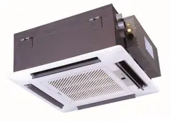
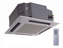
Cassette
Type
UMAT18HP230V1AC
ET010N0801
17100/18400
208/230V~60Hz
UMAT24HP230V1AC
ET010N0811
23800/27200
208/230V~60Hz
UMAT30HP230V1AC
ET010N0840
28200/31200
208/230V~60Hz
UMAT36HP230V1AC
ET010N0821
34000/41000
208/230V~60Hz
UMAT42HP230V1AC
ET010N0850
39500/44000
208/230V~60Hz
UMAT48HP230V1AC
ET010N0831
48000/54500
208/230V~60Hz
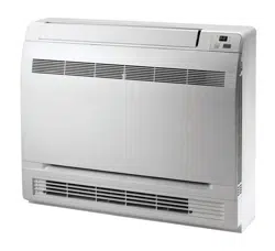
Floor/Ceiling
Type
UMAT18HP230V1AF
ED020N1081
17100/19100
208/230V~60Hz
UMAT24HP230V1AF
ED020N1091
23800/27200
208/230V~60Hz
UMAT30HP230V1AF
ED020N1120
28200/31200
208/230V~60Hz
UMAT36HP230V1AF
ED020N1101
34000/41000
208/230V~60Hz
UMAT42HP230V1AF
ED020N1130
39500/44000
208/230V~60Hz
UMAT48HP230V1AF
ED020N1111
48000/54500
208/230V~60Hz
Note: 1 Ton =12000Btu/h = 3.517kW
Note: The universal outdoor units means that the customer can choose any of three kind of indoor unit to
match the outdoor unit without any change with it.
U-Match Series DC Inverter Service Manual
4
2 NOMENCLATURE
2.1 Outdoor Unit
G
U
H
D
18
N
D
3
F
O
1
2
3
4
5
6
7
8
9
10
NO.
Description
Options
1
Gree Electric Appliances Inc
Capital Letter :G
2
Unit Type
U=U-Match Outdoor Unit
3
Product Type
C=Cool Only
H=Heat Pump without Aux Electric Heaters
4
Compressor Power Supply
Type Code
N=Constant Frequency
D=DC Inverter
A=AC Inverter
5
Nominal Cooling Capacity
Nominal Cooling Capacity=Number×1000Btu/h
6
Climate Type
N=Climate T1 Condition
T= Climate T3 Condition
7
Power Supply Code
K= 220-240V~ 50Hz
M=380-415V 3N~ 50Hz
D=208/230V ~ 60Hz
8
Refrigerant
1 =R22; 2=R407C; 3=R410A
9
Design Code
Design Code: A, B, C, D……
Design Change Code=0 (default)
1,2,3......
10
Unit Code
O=Outdoor unit
2.2 Indoor Unit
G
F
H
18
T
D
3
F
I
1
2
3
4
5
6
7
8
9
NO.
Description
Options
1
Gree Electric Appliances Inc
Capital Letter: G
2
Unit Type
F=Duct Type; K=Cassette Type; T=Floor-ceiling Type
3
Product Type
C=Cool Only; H=Heat Pump without Aux Electric Heaters
4
Nominal Cooling Capacity
Nominal Cooling Capacity=Number×1000Btu/h
5
Climate Type
Omit=Climate T1 Condition;
T=Climate T3 Condition
6
Power Supply Code
K=220-240V~ 50Hz
M=380-415V 3N~ 50Hz
D=208/230V ~ 60Hz
7
Refrigerant
1=R22; 2=R407C; 3=R410A
8
Design Code
Design Code: A, B, C, D……
Design Change Code=0 (default)
1,2,3......
9
Unit Code
I=indoor unite
U-Match Series DC Inverter Service Manual
5
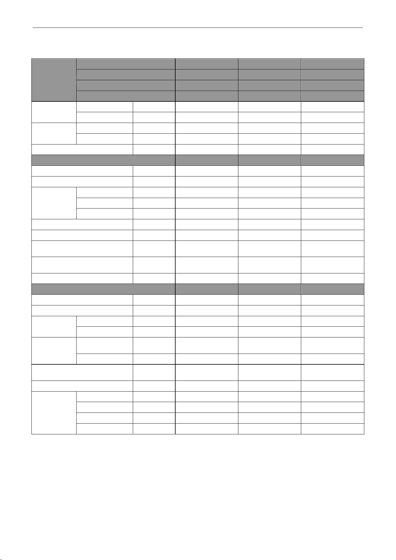
3 PRODUCT DATA
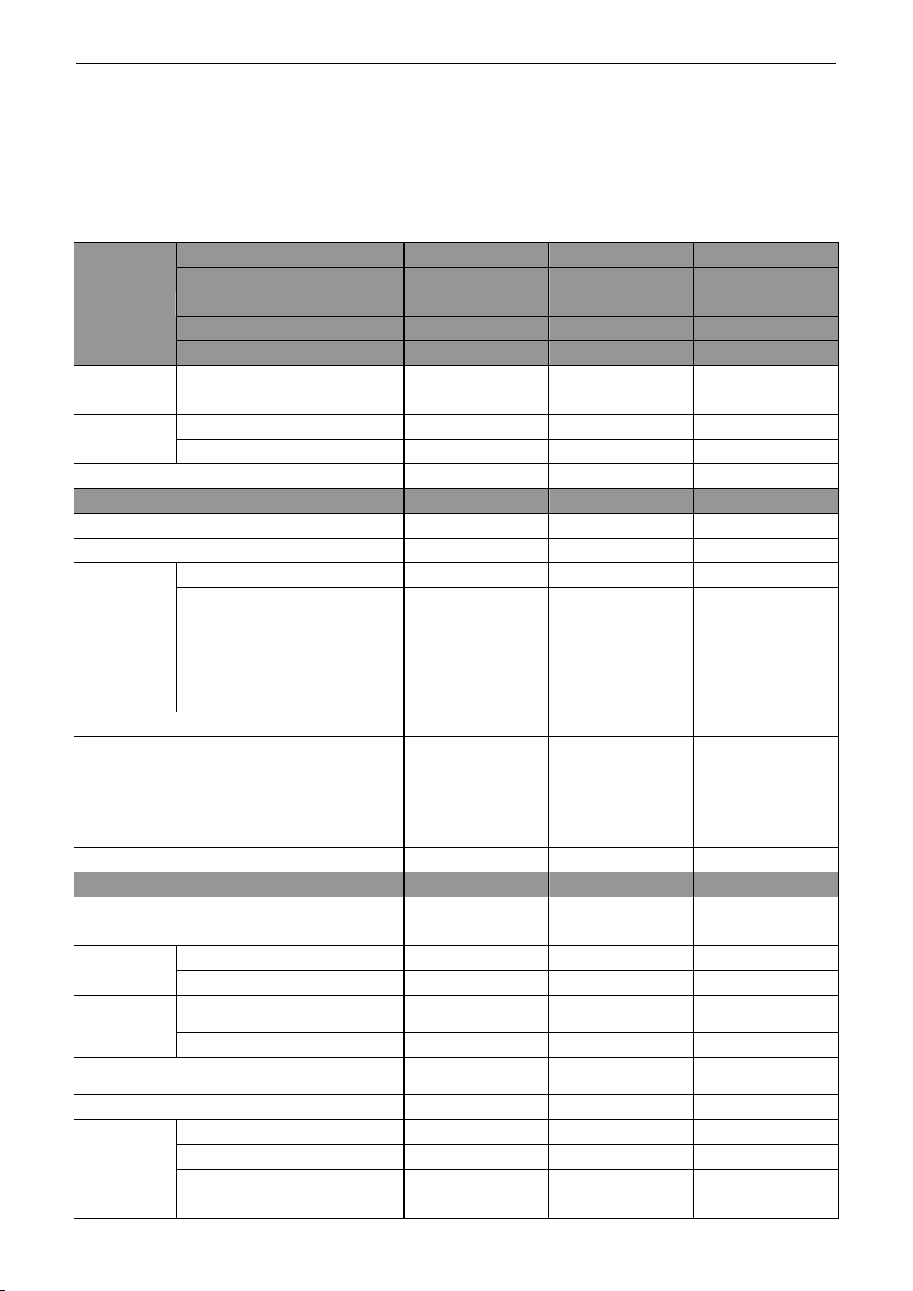
3.1 Product Data of Indoor Unit
3.1.1 Duct Type
Model
Indoor unit
UMAT18HP230V1AD UMAT24HP230V1AD UMAT30HP230V1AD
Product Code
CF060N0512
CF060N0513
CF060N0522
CF060N0523
CF060N0580
CF060N0590
Outdoor unit
UMAT18HP230V1AO UMAT24HP230V1AO UMAT30HP230V1AO
Product Code
CF090W0751
CF090W0761
CF090W0830
Capacity
Cooling Capacity
Btu/h
17100(5400~19800)
23800(7400~29000)
28200(8200~29600)
Heating Capacity
Btu/h
18800(4700~23200)
27200(8200~32400)
31200(8200~33600)
Power Input
Cooling
kW
1.55(0.55~1.75)
2.23(0.85~2.50)
3.30(0.85~3.70)
Heating
kW
1.65(0.50~1.90)
2.36(0.80~2.75)
3.10(0.80~3.50)
SEER / HSPF
(Btu/h)/W
16.00/9.50
16.00/10.00
16.00/9.00
Indoor Unit
UMAT18HP230V1AD UMAT24HP230V1AD UMAT30HP230V1AD
Power Supply
V/Ph/Hz
208/230V~60Hz
208/230V~60Hz
208/230V~60Hz
Heat Exchange
-
Cross Fin Coil
Cross Fin Coil
Cross Fin Coil
Fan
Drive
-
Direct
Direct
Direct
Motor Output
kW
0.06×1
0.15×1
0.15×1
Air Flow
m
3
/h(CFM)
1000(585)
1400(820)
1400(820)
Rated Ext. Static
Pressure
Pa(InWg)
25(0.1)
25(0.1)
37(0.15)
Ext. Static Pressure
Range
Pa(InWg)
0~30(0~0.12)
0~75(0~0.3)
0~75(0~0.3)
Sound Pressure Level(SS/H/M/L)
dB(A)
40/39/36/28
47/46/44/40
47/46/44/40
Air Filter
-
PP
PPKZ
PPKZ
Drain Piping
mm(inch)
Φ30×1.5
(Φ1.18×0.06)
Φ20×1.2
(Φ0.79×0.05)
Φ20×1.2
(Φ0.79×0.05)
Outline Dimensions (W×H×D)
mm
(inch)
1035×265×720
(40.8×10.5×28.4)
1280×2 70×5 60
(50.4×10.6×22.0)
1280×2 70×5 60
(50.4×10.6×22.0)
Net Weight
kg(lb)
33.0(72.8)
34.0(75.0)
35.0(77.2)
Outdoor Unit
UMAT18HP230V1AO UMAT24HP230V1AO UMAT30HP230V1AO
Power Supply
V/Ph/Hz
208/230V~60Hz
208/230V~60Hz
208/230V~60Hz
Heat Exchange
-
Cross Fin Coil
Cross Fin Coil
Cross Fin Coil
Compressor
Type
-
Rotary
Rotary
Rotary
Power Input
W
1440
2550
2550
Refrigerant
Control
-
Electronic Expansion
Valve
Electronic Expansion
Valve
Electronic Expansion
Valve
Charge
kg(oz)
1.4(49.4)
2.2(77.6)
2.4(84.7)
Outline Dimensions (W×H×D)
mm(inch)
955×700×395
(37.6×27.6×15.6)
980×790×425
(38.6×31.1×16.8)
980×790×425
(38.6×31.1×16.8)
Net Weight
kg(lb)
48.0(105.8)
69.0(152.1)
72.0(158.8)
Piping
Connections
Liquid
Inch
Φ1/4
Φ3/8
Φ3/8
Gas
Inch
Φ1/2
Φ5/8
Φ5/8
Max. Length
m(ft)
50(164.0)
50(164.0)
50(164.0)
Max. Height
m(ft)
15(49.2)
15(49.2)
15(49.2)
U-Match Series DC Inverter Service Manual
6
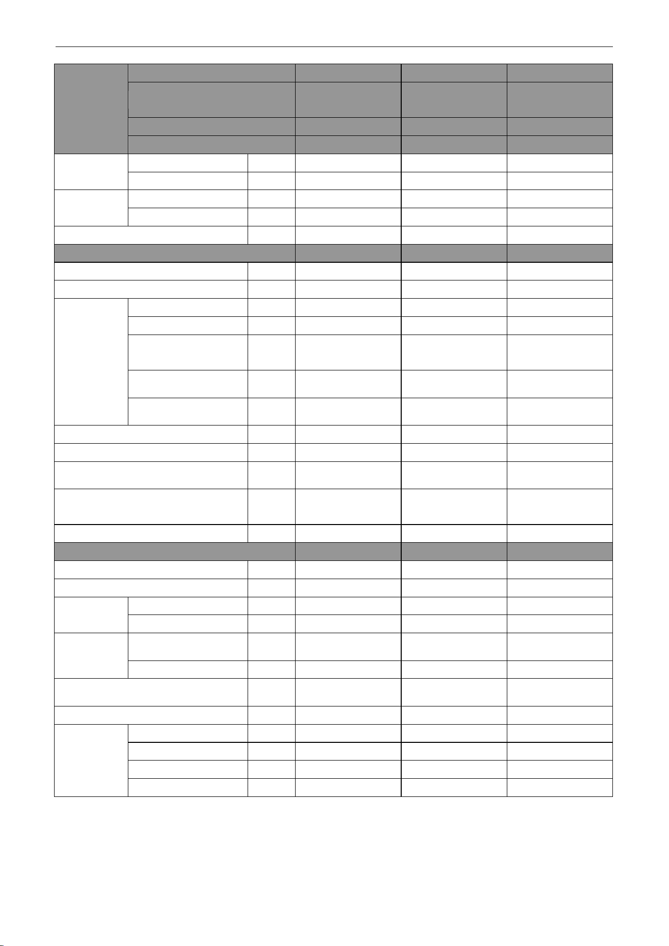
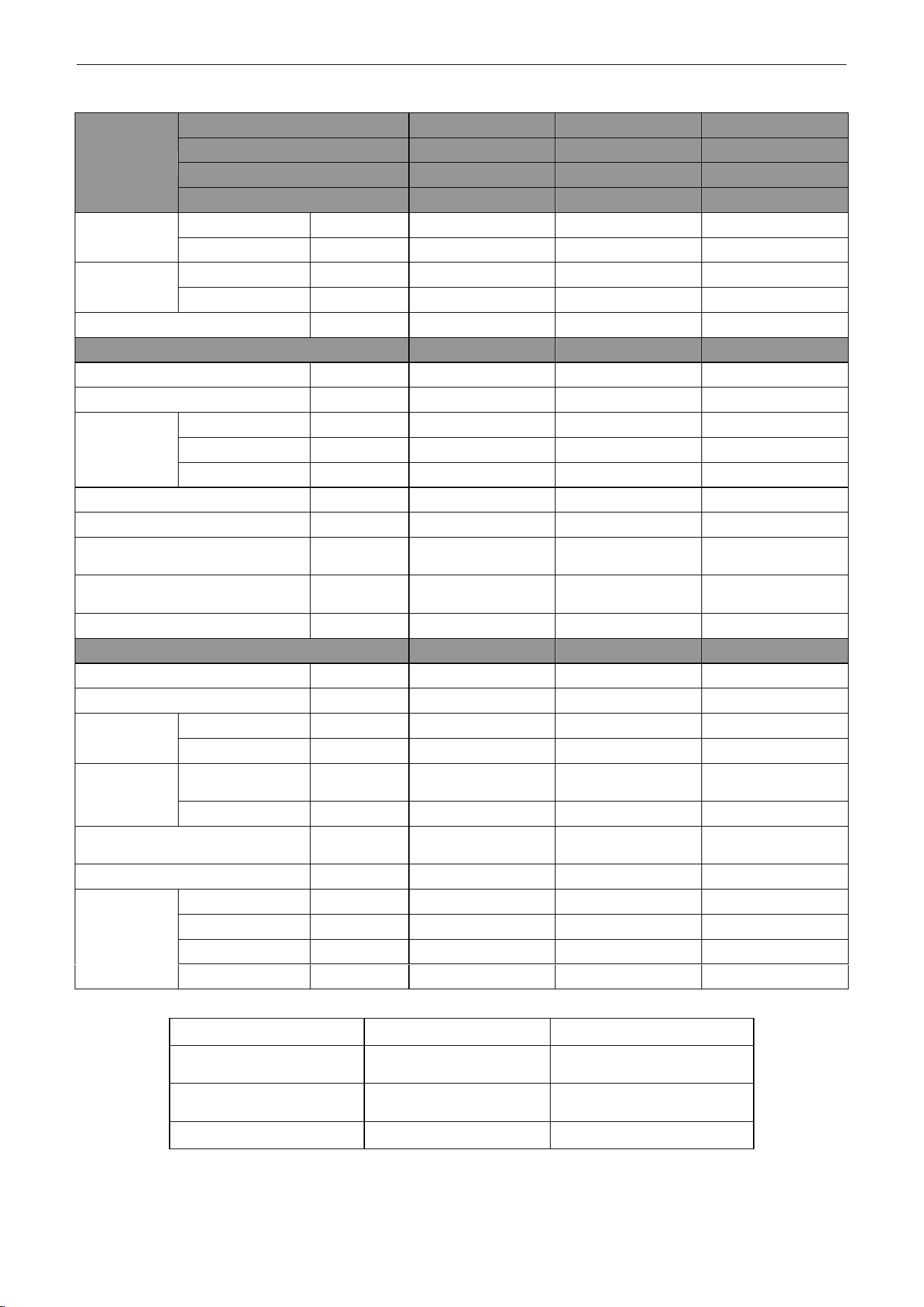
Model
Indoor unit
UMAT36HP230V1AD UMAT42HP230V1AD UMAT48HP230V1AD
Product Code
CF060N0532
CF060N0533
CF060N0600
CF060N0610
CF060N0542
CF060N0543
Outdoor unit
UMAT36HP230V1AO UMAT42HP230V1AO UMAT48HP230V1AO
Product Code
CF090W0771
CF090W0840
CF090W0781
Capacity
Cooling Capacity
Btu/h
34000(10800~39000)
39500(12000~42500)
48000(20400~49500)
Heating Capacity
Btu/h
41000(9800~49500)
44000(13000~52500)
54500(17500~58000)
Power Input
Cooling
kW
3.28(0.70~4.50)
4.15(0.65~4.70)
5.15(1.40~5.60)
Heating
kW
3.75(0.70~4.60)
3.90(0.76~4.75)
5.15(1.30~5.50)
SEER / HSPF
(Btu/h)/W
16.00/9.00
16.00/9.00
16.00/9.00
Indoor Unit
UMAT36HP230V1AD UMAT42HP230V1AD UMAT48HP230V1AD
Power Supply
V/Ph/Hz
208/230V~60Hz
208/230V~60Hz
208/230V~60Hz
Heat Exchange
-
Cross Fin Coil
Cross Fin Coil
Cross Fin Coil
Fan
Drive
-
Direct
Direct
Direct
Motor Output
kW
0.25×1
0.25×1
0.56×1
Air Flow
m
3
/h(CF
M)
2000(1175)
2000(1175)
2500(1470)
Rated Ext. Static
Pressure
Pa(InWg)
37(0.15)
37(0.15)
50(0.2)
Ext. Static Pressure
Range
Pa(InWg)
0~100(0~0.4)
0~100(0~0.4)
0~125(0~0.5)
Sound Pressure Level(SS/H/M/L)
dB(A)
53/52/48/44
53/52/48/44
55/53/49/45
Air Filter
-
PPKZ
PPKZ
PPKZ
Drain Piping
mm(inch)
Φ20×1.2
(Φ0.79×0.05)
Φ20×1.2
(Φ0.79×0.05)
Φ20×1.2
(Φ0.79×0.05)
Outline Dimensions (W×H×D)
mm
(inch)
1225×290×775
(48.3×11.4×30.5)
1225×290×775
(48.3×11.4×30.5)
1340×350×750
(52.8×13.8×29.5)
Net Weight
kg(lb)
46.0(101.4)
46.0(101.4)
56.0(123.5)
Outdoor Unit
UMAT36HP230V1AO UMAT42HP230V1AO UMAT48HP230V1AO
Power Supply
V/Ph/Hz
208/230V~60Hz
208/230V~60Hz
208/230V~60Hz
Heat Exchange
-
Cross Fin Coil
Cross Fin Coil
Cross Fin Coil
Compressor
Type
-
Rotary
Rotary
Rotary
Power Input
W
4150
4150
4580
Refrigerant
Control
-
Electronic Expansion
Valve
Electronic Expansion
Valve
Electronic Expansion
Valve
Charge
kg(oz)
3.5(123.5)
3.7(130.5)
4.0(141.1)
Outline Dimensions (W×H×D)
mm(inch)
1105×1100×440
(43.6×43.3×17.3)
960×1350×410
(37.7×53.1×16.2)
960×1350×410
(37.7×53.1×16.2)
Net Weight
kg(lb)
93.0(205.1)
95.0(209.5)
105.0(231.5)
Piping
Connections
Liquid
Inch
Φ3/8
Φ3/8
Φ3/8
Gas
Inch
Φ5/8
Φ5/8
Φ5/8
Max. Length
m(ft)
50(164.0)
50(164.0)
70(229.7)
Max. Height
m(ft)
15(49.2)
15(49.2)
15(49.2)
U-Match Series DC Inverter Service Manual
7
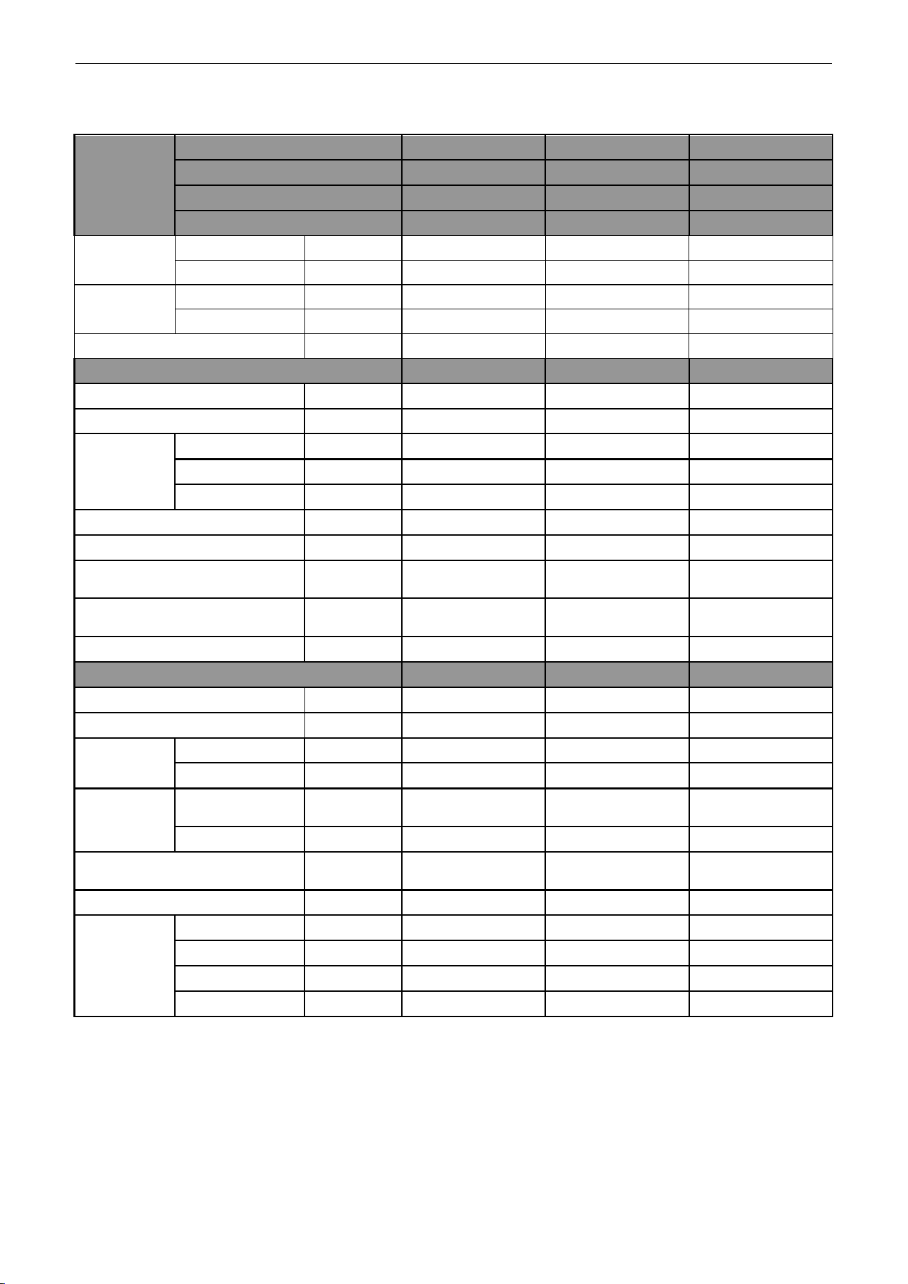
3.1.2 Cassette Type
Model
Indoor unit
UMAT18HP230V1AC UMAT24HP230V1AC UMAT30HP230V1AC
Product Code
ET010N0801
ET010N0811
ET010N0840
Outdoor unit
UMAT18HP230V1AO UMAT24HP230V1AO UMAT30HP230V1AO
Product Code
CF090W0751
CF090W0761
CF090W0830
Capacity
Cooling Capacity
Btu/h
17100(5400~18700)
23800(8200~29000)
28200(8800~31400)
Heating Capacity
Btu/h
18400(4700~22200)
27200(8200~32400)
31200(8200~33600)
Power Input
Cooling
kW
1.70(0.55~1.75)
2.23(0.85~2.50)
2.70(0.85~3.70)
Heating
kW
2.00(0.50~2.10)
2.36(0.80~2.75)
2.70(0.80~3.50)
SEER / HSPF
(Btu/h)/W
16.00/9.00
18.00/10.00
20.00/9.00
Indoor Unit
UMAT18HP230V1AC UMAT24HP230V1AC UMAT30HP230V1AC
Power Supply
V/Ph/Hz
208/230V~ 60Hz
208/230V~ 60Hz
208/230V~ 60Hz
Heat Exchange
-
Cross Fin Coil
Cross Fin Coil
Cross Fin Coil
Fan
Drive
-
Direct
Direct
Direct
Motor Output
kW
0.045×1
0.045×1
0.075×1
Air Flow
m
3
/h(CFM)
760(445)
1300(765)
1500(880)
Sound Pressure Level(SS/H/M/L)
dB(A)
47/46/44/37
47/46/42/38
49/48/45/40
Air Filter
-
PP
ABS+PP
ABS+PP
Drain Piping
mm(inch)
Φ25×1.5
(Φ0.98×0.06)
Φ25×1.5
(Φ0.98×0.06)
Φ25×1.5
(Φ0.98×0.06)
Outline Dimensions (W×H×D)
mm(inch)
665×240×595
(26.2×9.4×23.5)
915×240×840
(36.1×9.4×33.1)
915×320×840
(36.1×12.6×33.1)
Net Weight
kg(lb)
20.0(44.1)
27.0(59.5)
32.0(70.6)
Outdoor Unit
UMAT18HP230V1AO UMAT24HP230V1AO UMAT30HP230V1AO
Power Supply
V/Ph/Hz
208/230V~ 60Hz
208/230V~ 60Hz
208/230V~ 60Hz
Heat Exchange
-
Cross Fin Coil
Cross Fin Coil
Cross Fin Coil
Compressor
Type
-
Rotary
Rotary
Rotary
Power Input
W
1440
2550
2550
Refrigerant
Control
-
Electronic
Expansion Valve
Electronic
Expansion Valve
Electronic
Expansion Valve
Charge
kg(oz)
1.4(49.4)
2.2(77.6)
2.4(84.7)
Outline Dimensions (W×H×D)
mm(inch)
955×700×395
(37.6×27.6×15.6)
980×790×425
(38.6×31.1×16.8)
980×790×425
(38.6×31.1×16.8)
Net Weight
kg(lb)
48.0(105.8)
69.0(152.1)
72.0(158.8)
Piping
Connections
Liquid
Inch
Φ1/4
Φ3/8
Φ3/8
Gas
Inch
Φ1/2
Φ5/8
Φ5/8
Max. Length
m(ft)
50(164.0)
50(164.0)
50(164.0)
Max. Height
m(ft)
15(49.2)
15(49.2)
15(49.2)
U-Match Series DC Inverter Service Manual
8
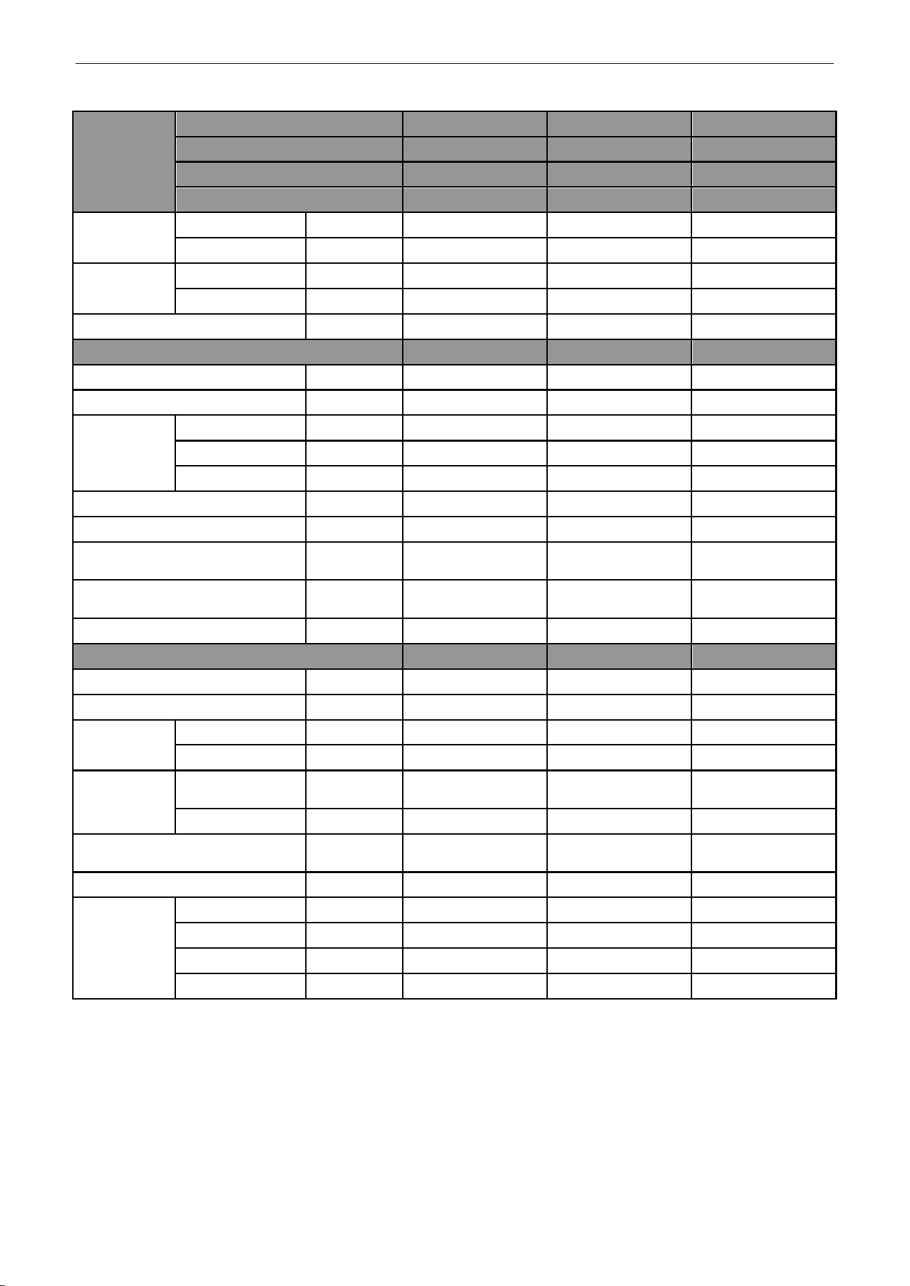
Model
Indoor unit
UMAT36HP230V1AC UMAT42HP230V1AC UMAT48HP230V1AC
Product Code
ET010N0821
ET010N0850
ET010N0831
Outdoor unit
UMAT36HP230V1AO
UMAT42HP230V1AO UMAT48HP230V1AO
Product Code
CF090W0771
CF090W0840
CF090W0781
Capacity
Cooling Capacity
Btu/h
34000(10800~39000)
39500(11000~41000)
48000(20400~50500)
Heating Capacity
Btu/h
41000(9800~49500)
44000(12000~51000)
54500(17500~61500)
Power Input
Cooling
kW
3.28(0.75~4.50)
4.40(0.53~4.65)
5.50(1.30~5.70)
Heating
kW
3.75(0.60~4.80)
4.45(0.64~4.80)
5.10 (1.20~5.40)
SEER / HSPF
(Btu/h)/W
16.00/9.00
16.00/9.00
16.00/9.00
Indoor Unit
UMAT36HP230V1AC UMAT42HP230V1AC UMAT48HP230V1AC
Power Supply
V/Ph/Hz
208/230V~ 60Hz
208/230V~ 60Hz
208/230V~ 60Hz
Heat Exchange
-
Cross Fin Coil
Cross Fin Coil
Cross Fin Coil
Fan
Drive
-
Direct
Direct
Direct
Motor Output
kW
0.075×1
0.075×1
0.1×1
Air Flow
m
3
/h(CFM)
1860(1095)
1860(1095)
2300(1350)
Sound Pressure Level(SS/H/M/L)
dB(A)
51/49/46/43
51/49/46/43
53/52/47/41
Air Filter
-
ABS+PP
ABS+PP
ABS+PP
Drain Piping
mm(inch)
Φ25×1.5
(Φ0.98×0.06)
Φ25×1.5
(Φ0.98×0.06)
Φ25×1.5
(Φ0.98×0.06)
Outline Dimensions (W×H×D)
mm(inch)
915×320×840
(36.1×12.6×33.1)
915×320×840
(36.1×12.6×33.1)
910×290×910
(35.8×11.4×35.8)
Net Weight
kg(lb)
32.0(70.6)
32.0(70.6)
43.0(94.8)
Outdoor Unit
UMAT36HP230V1AO UMAT42HP230V1AO UMAT48HP230V1AO
Power Supply
V/Ph/Hz
208/230V~ 60Hz
208/230V~ 60Hz
208/230V~ 60Hz
Heat Exchange
-
Cross Fin Coil
Cross Fin Coil
Cross Fin Coil
Compressor
Type
-
Rotary
Rotary
Rotary
Power Input
W
4150
4150
4580
Refrigerant
Control
-
Electronic
Expansion Valve
Electronic
Expansion Valve
Electronic
Expansion Valve
Charge
kg(oz)
3.5(123.5)
3.7(130.5)
4.0(141.1)
Outline Dimensions (W×H×D)
mm(inch)
1105×1100×440
(43.6×43.3×17.3)
960×1350×410
(37.7×53.1×16.2)
960×1350×410
(37.7×53.1×16.2)
Net Weight
kg(lb)
93.0(205.1)
95.0(209.5)
105.0(231.5)
Piping
Connections
Liquid
Inch
Φ3/8
Φ3/8
Φ3/8
Gas
Inch
Φ5/8
Φ5/8
Φ5/8
Max. Length
m(ft)
50(164.0)
50(164.0)
70(229.7)
Max. Height
m(ft)
15(49.2)
15(49.2)
15(49.2)
U-Match Series DC Inverter Service Manual
9
3.1.3 Floor-ceiling Type
Model
Indoor unit
UMAT18HP230V1AF UMAT24HP230V1AF UMAT30HP230V1AF
Product Code
ED020N1081
ED020N1091
ED020N1120
Outdoor unit
UMAT18HP230V1AO UMAT24HP230V1AO UMAT30HP230V1AO
Product Code
CF090W0751
CF090W0761
CF090W0830
Capacity
Cooling Capacity
Btu/h
17100(5400~19800)
23800(8200~27800)
28200(8800~31400)
Heating Capacity
Btu/h
19100(4700~23200)
27200(8200~30600)
31200(8200~33600)
Power Input
Cooling
kW
1.55(0.55~1.75)
2.23(0.85~2.50)
2.70(0.85~3.70)
Heating
kW
1.70(0.50~1.90)
2.36(0.80~2.75)
2.60(0.80~3.50)
SEER / HSPF
(Btu/h)/W
17.00/9.50
16.00/10.00
17.00/9.00
Indoor Unit
UMAT18HP230V1AF UMAT24HP230V1AF UMAT30HP230V1AF
Power Supply
V/Ph/Hz
208/230V~ 60Hz
208/230V~ 60Hz
208/230V~ 60Hz
Heat Exchange
-
Cross Fin Coil
Cross Fin Coil
Cross Fin Coil
Fan
Drive
-
Direct
Direct
Direct
Motor Output
kW
0.06×1
0.06×1
0.15×1
Air Flow
m
3
/h(CFM)
1000(585)
1200(705)
1500(880)
Sound Pressure Level(SS/H/M/L)
dB(A)
44/42/38/32
49/48/46/40
49/46/44/38
Air Filter
-
PP
PP
PP
Drain Piping
mm(inch)
Φ17×1.75
(Φ0.67×0.07)
Φ17×1.75
(Φ0.67×0.07)
Φ17×1.75
(Φ0.67×0.07)
Outline Dimensions (W×H×D)
mm(inch)
1220×225×700
(48.0×8.9×27.6)
1220×225×700
(48.0×8.9×27.6)
1420×245×700
(55.9×9.6×27.6)
Net Weight
kg(lb)
39.0(86.0)
40.0(88.2)
48.0(105.8)
Outdoor Unit
UMAT18HP230V1AO UMAT24HP230V1AO UMAT30HP230V1AO
Power Supply
V/Ph/Hz
208/230V~ 60Hz
208/230V~ 60Hz
208/230V~ 60Hz
Heat Exchange
-
Cross Fin Coil
Cross Fin Coil
Cross Fin Coil
Compressor
Type
-
Rotary
Rotary
Rotary
Power Input
W
1440
2550
2550
Refrigerant
Control
-
Electronic Expansion
Valve
Electronic Expansion
Valve
Electronic Expansion
Valve
Charge
kg(oz)
1.4(49.4)
2.2(77.6)
2.4(84.7)
Outline Dimensions (W×H×D)
mm(inch)
955×700×395
(37.6×27.6×15.6)
980×790×425
(38.6×31.1×16.8)
980×790×425
(38.6×31.1×16.8)
Net Weight
kg(lb)
48.0(105.8)
69.0(152.1)
72.0(158.8)
Piping
Connections
Liquid
Inch
Φ1/4
Φ3/8
Φ3/8
Gas
Inch
Φ1/2
Φ5/8
Φ5/8
Max. Length
m(ft)
50(164.0)
50(164.0)
50(164.0)
Max. Height
m(ft)
15(49.2)
15(49.2)
15(49.2)
U-Match Series DC Inverter Service Manual
10
Model
Indoor unit
UMAT36HP230V1AF UMAT42HP230V1AF UMAT48HP230V1AF
Product Code
ED020N1101
ED020N1130
ED020N1111
Outdoor unit
UMAT36HP230V1AO UMAT42HP230V1AO UMAT48HP230V1AO
Product Code
CF090W0771
CF090W0840
CF090W0781
Capacity
Cooling Capacity
Btu/h
34000(10800~39000)
39500(12000~42500)
48000(20400~50500)
Heating Capacity
Btu/h
41000(9800~49500)
44000(13000~52500)
54500(17500~61500)
Power Input
Cooling
kW
3.28(0.80~4.60)
4.05(0.60~4.70)
5.50(1.30~5. 70)
Heating
kW
3.75(0.65~4.80)
4.05(0.69~4.80)
4.60(1.20~5.40)
SEER / HSPF
(Btu/h)/W
16.00/9.00
16.00/9.00
16.00/9.00
Indoor Unit
UMAT36HP230V1AF UMAT42HP230V1AF UMAT48HP230V1AF
Power Supply
V/Ph/Hz
208/230V~ 60Hz
208/230V~ 60Hz
208/230V~ 60Hz
Heat Exchange
-
Cross Fin Coil
Cross Fin Coil
Cross Fin Coil
Fan
Drive
-
Direct
Direct
Direct
Motor Output
kW
0.15×1
0.15×1
0.25×1
Air Flow
m
3
/h(CFM)
1900(1115)
1900(1115)
2300(1350)
Sound Pressure Level(SS/H/M/L)
dB(A)
54/53/51/46
55/54/52/47
56/55/50/46
Air Filter
-
PP
PP
PP
Drain Piping
mm(inch)
Φ17×1.75
(φ0.67×0.07)
Φ17×1.75
(φ0.67×0.07)
Φ17×1.75
(φ0.67×0.07)
Outline Dimensions (W×H×D)
mm(inch)
1420×245×700
(55.9×9.6×27.6)
1420×245×700
(55.9×9.6×27.6)
1700×245×700
(66.9×9.6×27.6)
Net Weight
kg(lb)
48.0(105.8)
50.0(110.3)
59.0(130.1)
Outdoor Unit
UMAT36HP230V1AO UMAT42HP230V1AO UMAT48HP230V1AO
Power Supply
V/Ph/Hz
208/230V~ 60Hz
208/230V~ 60Hz
208/230V~ 60Hz
Heat Exchange
-
Cross Fin Coil
Cross Fin Coil
Cross Fin Coil
Compressor
Type
-
Rotary
Rotary
Rotary
Power Input
W
4150
4150
4580
Refrigerant
Control
-
Electronic Expansion
Valve
Electronic Expansion
Valve
Electronic Expansion
Valve
Charge
kg(oz)
3.5(123.5)
3.7(130.5)
4.0(141.1)
Outline Dimensions (W×H×D)
mm(inch)
1105×1100×440
(43.6×43.3×17.3)
960×1350×410
(37.7×53.1×16.2)
960×1350×410
(37.7×53.1×16.2)
Net Weight
kg(lb)
93.0(205.1)
95.0(209.5)
105.0(231.5)
Piping
Connections
Liquid
Inch
Φ3/8
Φ3/8
Φ3/8
Gas
Inch
Φ5/8
Φ5/8
Φ5/8
Max. Length
m(ft)
50(164.0)
50(164.0)
70(229.7)
Max. Height
m(ft)
15(49.2)
15(49.2)
15(49.2)
Note:
Nominal capacities are based on the follow conditions.
Indoor
Outdoor
Cooling
DB: 26.7℃(80.0℉)
WB: 19.4℃(67.0℉)
DB: 35.0℃(95.0℉)
WB: 23.9℃(75.0℉)
Heating
DB: 21.1℃(70.0℉)
WB: 15.6℃(60.0℉)
DB: 8.33℃(47.0℉)
WB: 6.11℃(43.0℉)
Piping Length
18k~48k units
7.6m(25.0ft)
The air volume is measured at the relevant standard external static pressure.
Noise is tested in the Semi anechoic room, so it should be slightly higher in the actual operation due to
environmental change.
U-Match Series DC Inverter Service Manual
11
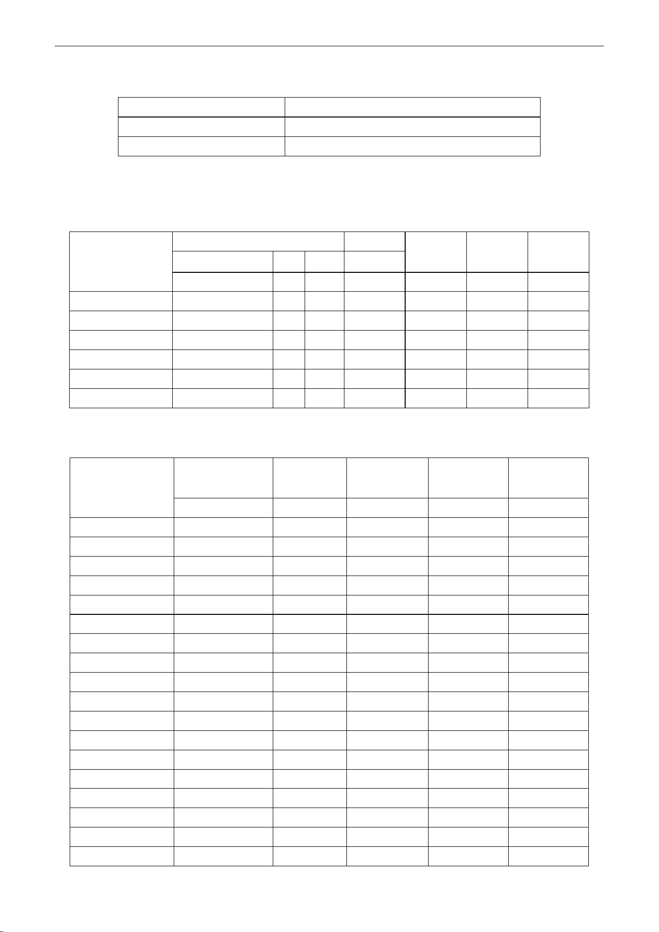
3.2 Operation Range
Mode
Range of Outdoor Temperature
Cooling
-18.0℃(0℉)~48.0℃(118.4℉)
Heating
-18.0℃(0℉)~24.0℃(75.2℉)
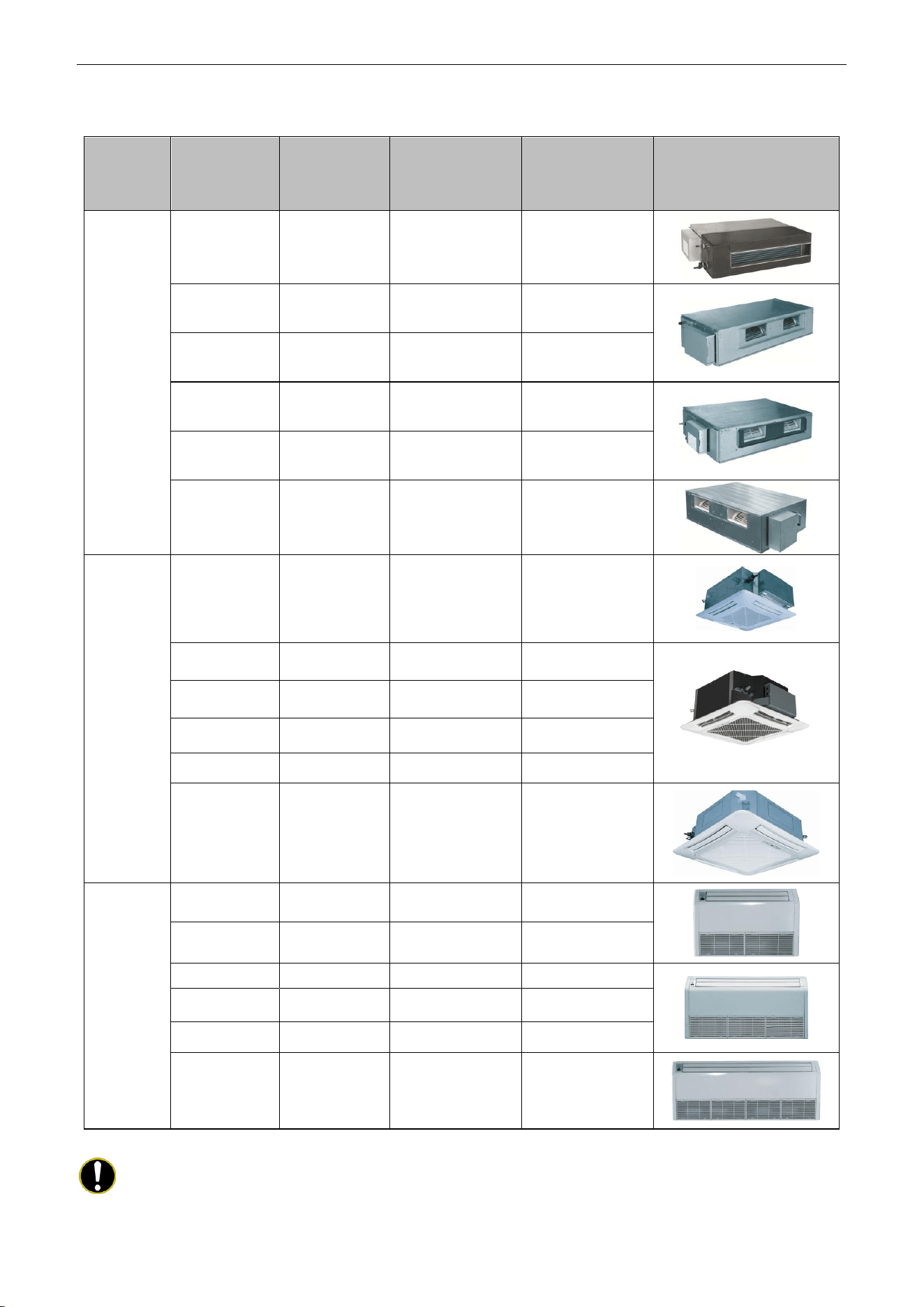
3.3 Electrical Data
3.3.1 Outdoor unit
Table 1-3-1 Electrical Data of Outdoor Unit
Model
Compressor
Fan Motor
Fuse/Breaker
Capacity
Minimum
Circuit
Ampacity
Maximum
Overcurrent
Protection
Power Supply
Qty.
RLA
FLA
V/Ph/Hz
−
A
A
A
A
A
UMAT18HP230V1AO
208/230V ~ 60Hz
1
12.0
1.5
5/25
17
25
UMAT24HP230V1AO
208/230V ~ 60Hz
1
18.0
1.5
5/40
24
40
UMAT30HP230V1AO
208/230V ~ 60Hz
1
18.0
1.5
5/40
24
40
UMAT36HP230V1AO
208/230V ~ 60Hz
1
21.2
2.0
5/45
29
45
UMAT42HP230V1AO
208/230V ~ 60Hz
1
21.2
2*2.0
5/50
31
50
UMAT48HP230V1AO
208/230V ~ 60Hz
1
32.5
2*2.0
5/70
45
70
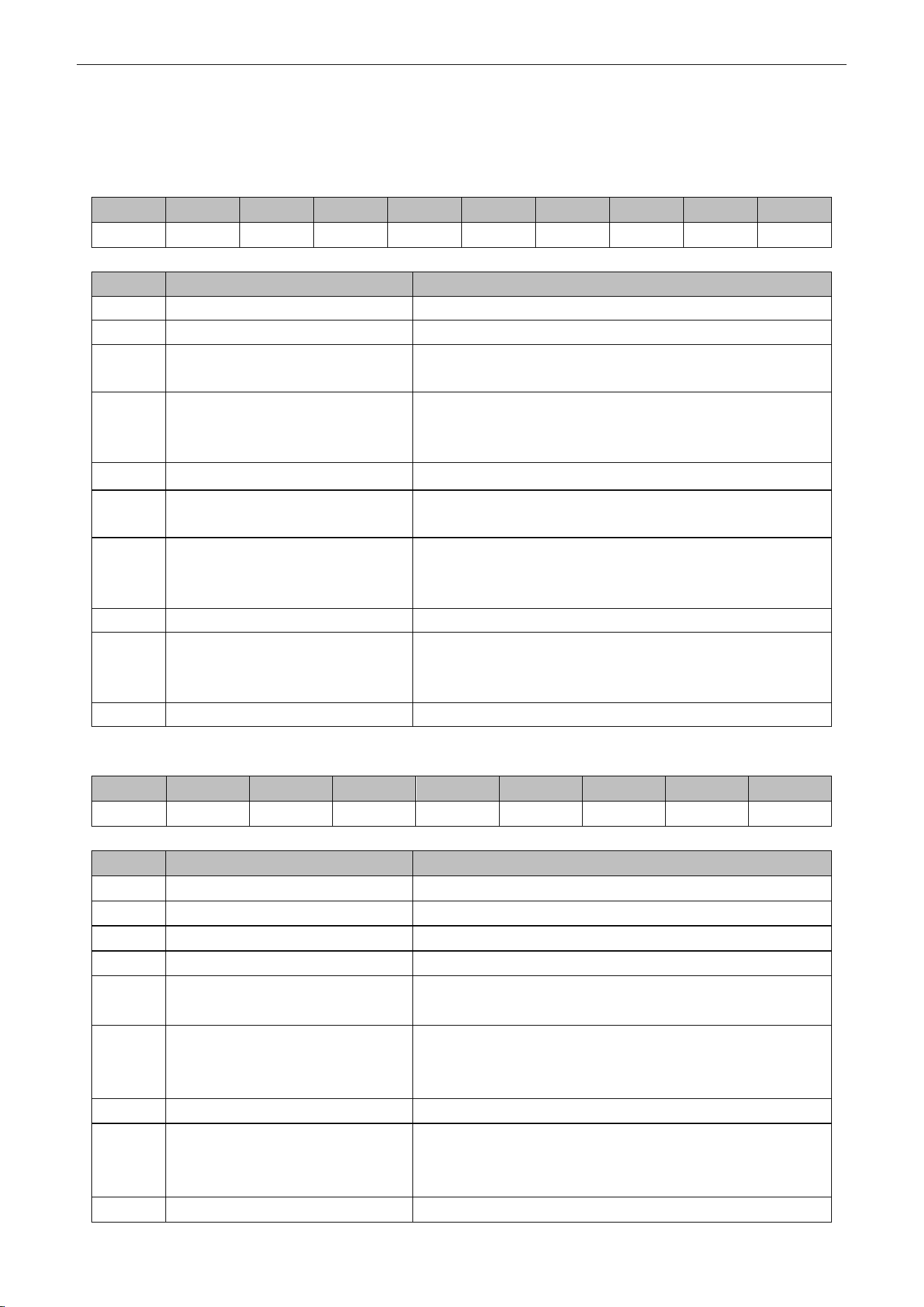
3.3.2 Indoor unit
Table 1-3-2 Electrical Data of Indoor Unit
Model
Power Supply
Fan Motor FLA
Fuse/Breaker
Capacity
Minimum Circuit
Ampacity
Maximum
Overcurrent
Protection
V/Ph/Hz
A
A
A
A
UMAT18HP230V1AD
208V/230V ~ 60Hz
0.6
5/15
1
15
UMAT24HP230V1AD
208V/230V ~ 60Hz
1.3
5/15
2
15
UMAT30HP230V1AD
208V/230V ~ 60Hz
1.3
5/15
2
15
UMAT36HP230V1AD
208V/230V ~ 60Hz
2.1
5/15
3
15
UMAT42HP230V1AD
208V/230V ~ 60Hz
2.1
5/15
3
15
UMAT48HP230V1AD
208V/230V ~ 60Hz
4.0
5/15
5
15
UMAT18HP230V1AC
208V/230V ~ 60Hz
0.5
5/15
1
15
UMAT24HP230V1AC
208V/230V ~ 60Hz
0.5
5/15
1
15
UMAT30HP230V1AC
208V/230V ~ 60Hz
0.9
5/15
1.5
15
UMAT36HP230V1AC
208V/230V ~ 60Hz
0.9
5/15
1.5
15
UMAT42HP230V1AC
208V/230V ~ 60Hz
0.9
5/15
1.5
15
UMAT48HP230V1AC
208V/230V ~ 60Hz
1.5
5/15
2
15
UMAT18HP230V1AF
208V/230V ~ 60Hz
0.6
5/15
1
15
UMAT24HP230V1AF
208V/230V ~ 60Hz
0.6
5/15
1
15
UMAT30HP230V1AF
208V/230V ~ 60Hz
1.4
5/15
2
15
UMAT36HP230V1AF
208V/230V ~ 60Hz
1.4
5/15
2
15
UMAT42HP230V1AF
208V/230V ~ 60Hz
1.4
5/15
2
15
UMAT48HP230V1AF
208V/230V ~ 60Hz
2.1
5/15
3
15
U-Match Series DC Inverter Service Manual
12
Notes:
RLA: Rated load amperes (marked in the nameplate of the outdoor unit)
FLA: Full load current
① The fuse is located on the main board.
② Install the disconnect device with a contact gap of at least 3mm (1/8inch) in all poles nearby
the units (Both indoor unit and outdoor unit).The appliance must be positioned so that the
plug is accessible.
③ Take 2 pieces of power cord of 0.75mm
2
(AWG18) as the communication lines between
indoor and outdoor unit, with their longest lengths of 50m (164feet). Please select the
appropriate line length as per the actual installation conditions. The communication lines can
not be twisted together. For the unit (
≤
30k), it’s recommended to use 8m (26-1/4feet) long
communication line.
④ Take 2 pieces of power cord of 0.75mm
2
(AWG18) as the communication lines between the
wired controller and the indoor unit, with their longest lengths of 30m (98-2/5feet). Please
select the appropriate line length as per the actual installation conditions. The
communication lines can not be twisted together. It’s recommended to use 8m (26-1/4feet)
long communication line.
⑤ The wire size of the communication line should be no less than 0.75mm
2
(AWG18). It’s
recommended to take 0.75mm
2
(AWG18) power cords as the communication line.
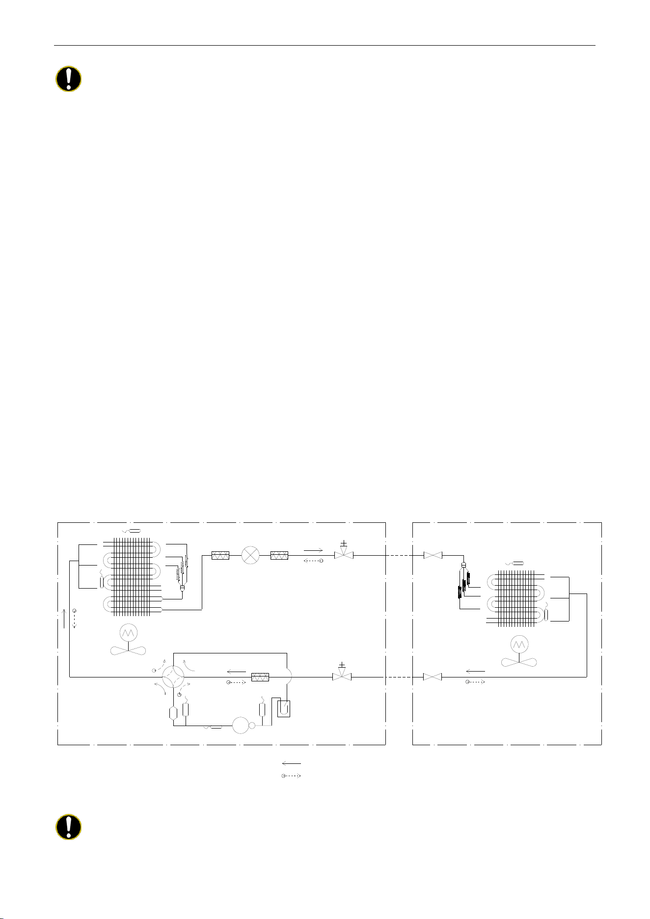
4 PIPING DIAGRAM
Indoor Unit
Outdoor Unit
TH-OE
TH-D
Condenser
Filter
Electronic Expansion Valve
Liquid Solid Valve
with Service Port
Liquid Solid
Valve
4-Way Valve
Muffler
TH-C
Low Pressure Switch
Accumulator
High Pressure
Switch
Compressor
Gas Stop Valve
with Service Port
Gas Stop
Valve
TH-IE
Evaporator
TH-E
Cooling
Heating
TH-OE: Outdoor Environment Thermal Bulb
TH-C: Outdoor Condenser Thermal Bulb
TH-D: Compressor Discharge Thermal Bulb
TH-IE: Indoor Environment Thermal Bulb
TH-E: Indoor Evaporator Thermal Bulb
Filter
Filter
Notes:
It is just a schematic diagram and some parts may differ from the real objects inside the unit.

U-Match Series DC Inverter Service Manual
13
CONTROL
U-Match Series DC Inverter Service Manual
14
CONTROL
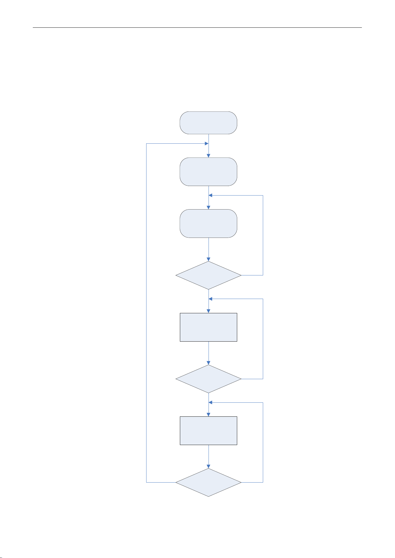
1 OPERATION FLOWCHART
1.1 Cooling/Dry Operation
Satisfying open
Comp. condition
Temp of indoor
≤Set temp
Comp. stop
for 3 min
NY
N
Y
Y
N
Open unit running at
cool or dry mode
Indoor fan run
Comp. and outdoor
fan run
Comp. and
outdoor fan stop
Power
On
U-Match Series DC Inverter Service Manual
15
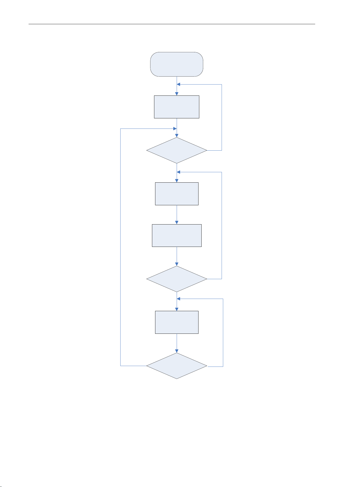
1.2 Heating Operation
Satisfying open
comp. condition
N
Y
N
Y
Y
N
Power
On
Comp. and
outdoor
fan run
Avoid cool wind
(only when comp.
start)
Temp of indoor
≥Set temp
Comp. and
outdoor fan stop
Comp. stop
for 3 min
Open unit running
at heat mode
U-Match Series DC Inverter Service Manual
16
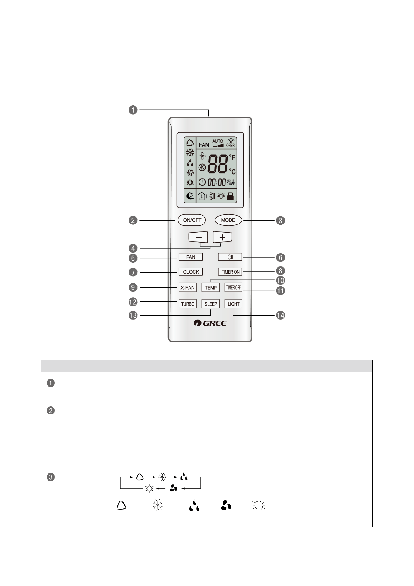
2 WIRELESS REMOTE CONTROLLER
2.1 Operation and Display View
Table 2-2-1 Operation instruction of wireless remote controller
No.
Name
Function Description
Signal
transmitter
Signal transmitter
ON/OFF
button
Press this button and the unit will be turned on; press it once more and the unit will be
turned off. When turning off the unit, the Sleep function will be canceled, but the
presetting time is still remained.
MODE
button
By pressing this button, Auto, Cool, Dry, Fan, Heat mode can be selected circularly.
Auto mode is default after power on. Under the Auto mode, the setting temperature will
not be displayed; Under the Heat mode, the initial value is 28°C (82°F); under other
modes, the initial value is 25°C (77°F).
AUTO; COOL; DRY; FAN; HEAT (only for cooling and heating
unit)
U-Match Series DC Inverter Service Manual
17
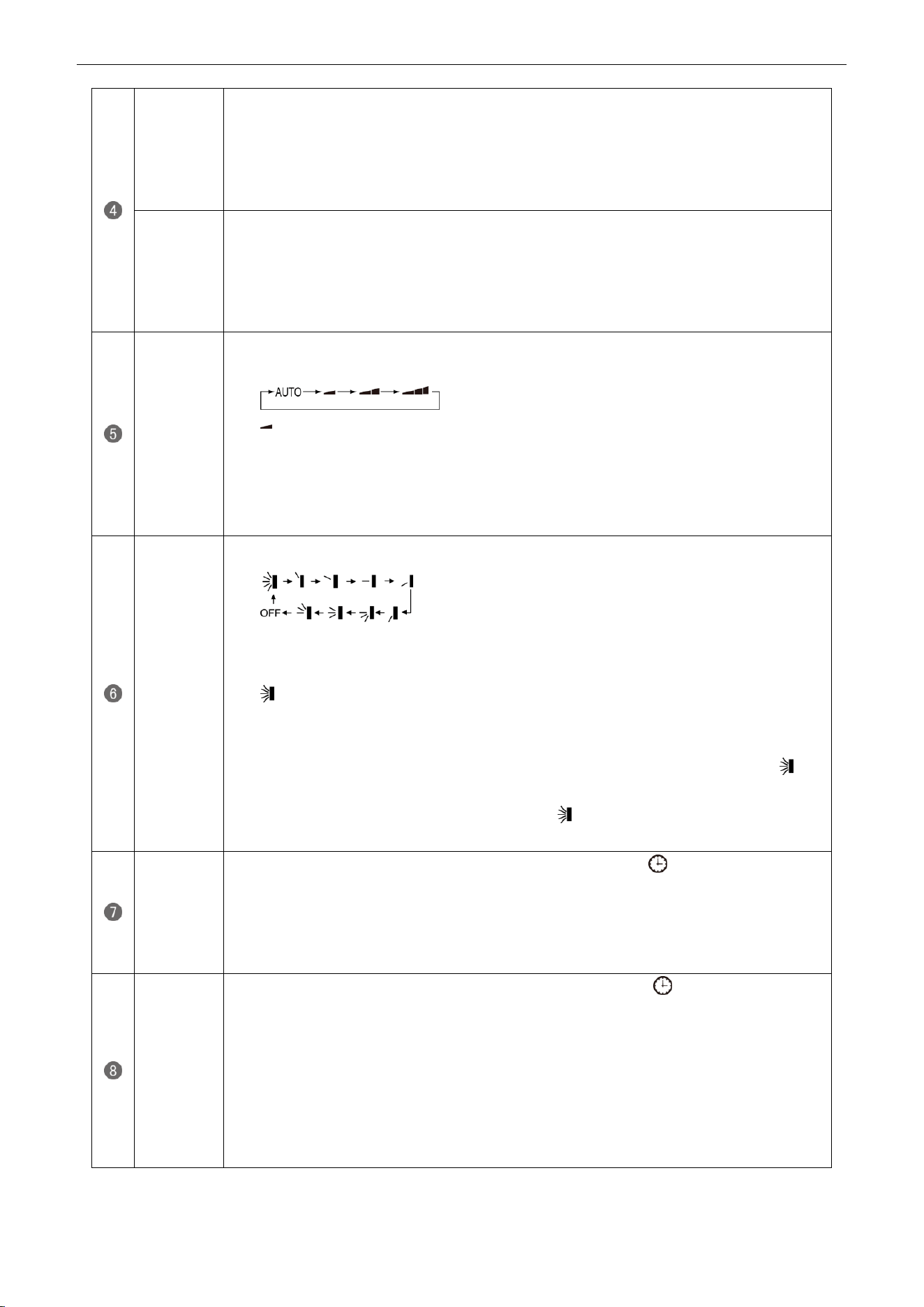
- button
Preset temperature can be decreased by pressing this button. Pressing and holding this
button for more than 2 seconds can make the temperature changed quickly until release
this button and then transmit this order. The temperature adjustment is unavailable under
the Auto mode, but the order can be sent by pressing this button. Centigrade setting
range: 16~30; Fahrenheit scale setting range 61~86.
+ button
Preset temperature can be increased by pressing this button. Pressing and holding this
button for more than 2 seconds can make the temperature changed quickly until release
the button and then transmit this order. The temperature adjustment is unavailable under
the Auto mode, but the order can be sent by pressing this button. Centigrade setting
range: 16~30; Fahrenheit scale setting range 61~86.
FAN button
By pressing this button, Auto, Low, Middle, High speed can be circularly selected. After
power on, Auto fan speed is default.
Low speed
Middle speed
High speed
Note: Under the DRY mode, the fan will be kept running at the low speed and the fan speed
isn't adjustable.
SWING
UP/DOWN
button
Press this button to set up the swing angle, which circularly changes as below:
When the guide louver starts to swing up and down, if SWING functions are canceled, the
air guide louver will stop and remains at the current position.
Indicates the guide louver swings up and down among those five directions
(Simplified SWING function applicable for some Fan Coil Units: When the wireless
remote controller is energized initially with the unit under the OFF status, it should be set
by pressing the + button and the SWING button simultaneously, with the symbol
blinking twice. Then, after the unit is turned on, this function can be activated by pressing
the SWING button, with the displayed symbol indicating swing function is on and
without this displayed symbol indicating swing function is off).
CLOCK
button
By pressing this button, the clock is allowed to be set, with blinking, and then press
the +/- button to adjust the clock within 5 seconds. If the +/-button is pressed down
constantly for more than 2 seconds, the clock setting will be increased or decreased 10
minutes every 0.5 seconds. After that, another press on the CLOCK button accepts the
setting. 12:00 is the default, when the wireless remote controller is energized.
TIMER ON
button
When TIMER ON is activated, ON will blink while the symbol will disappear. Within 5
seconds it is allowed to set the ON time by pressing the +/- button. Each press will make
the time increase or decrease one minute. Besides, the time can also be set by pressing
the +/- button constantly. That is, in the early 2.5 seconds, the time will
increase/decrease quickly per single minute, and in the late 2.5, the time will
increase/decrease per ten minutes. After the desired time value is set, press TIENE ON
again to conform the setting within five seconds. After that, another press on TIMER ON
will cancel the setting. Prior to this setting, the clock shall be set to the actual time.
U-Match Series DC Inverter Service Manual
18
X-FAN
button
Pressing this button can activate or deactivate the X-FAN function. In Cool or Dry mode,
by pressing this button, if " " is displayed, it indicates the X-FAN function is activated.
By repressing this button, if " " disappears, it indicates the X-FAN function is
deactivated. After energizing, X-FAN OFF is defaulted. If the unit is turned off, X-FAN can
be deactivated but can't be activated.
TEMP
button
By pressing this button it is allowed to select displaying the indoor setting temperature or
the indoor ambient temperature.
Indoor setting temperature is default after the indoor unit is energized initially.
By pressing the TEMP button, when the temperature symbol is displayed, the indoor
displayer will show the indoor setting temperature; when is displayed, it will show the
indoor ambient temperature; when is invalidation, If current displays indoor ambient
temperature, if received the other remote control signal, it will display presetting
temperature, 5s later, will back to display the ambient temperature (This function is
applicable to partial of models).
TIMER
OFF button
By pressing this button it is available to go to the TIMER OFF setting state with the same
setting method as that of the TIMER ON, in which case the OFF symbol blinks.
TURBO
button
In the Cool or Heat mode, pressing this button can activate or deactivate the TURBO
function. When the TURBO function is activated, its symbol will be displayed; when
the running mode or the fan speed is changed, this function will be canceled
automatically (This function is applicable to partial of models).
SLEEP
button
By pressing this button, Sleep On and Sleep Off can be selected. After powered on,
Sleep Off is defaulted. Once the unit is turned off, the Sleep function is canceled. When
Sleep is set to On, the symbol of SLEEP will display. Under the Fan and Auto
modes, this function is not available.
LIGHT
button
Press this button to select LIGHT on or off in the displayer. When the LIGHT is set to on,
the icon will be displayed and the indicating light in the displayer will be on. When
the LIGHT is set to off, the icon will be disappeared and the indicating light in the
displayer will be off.
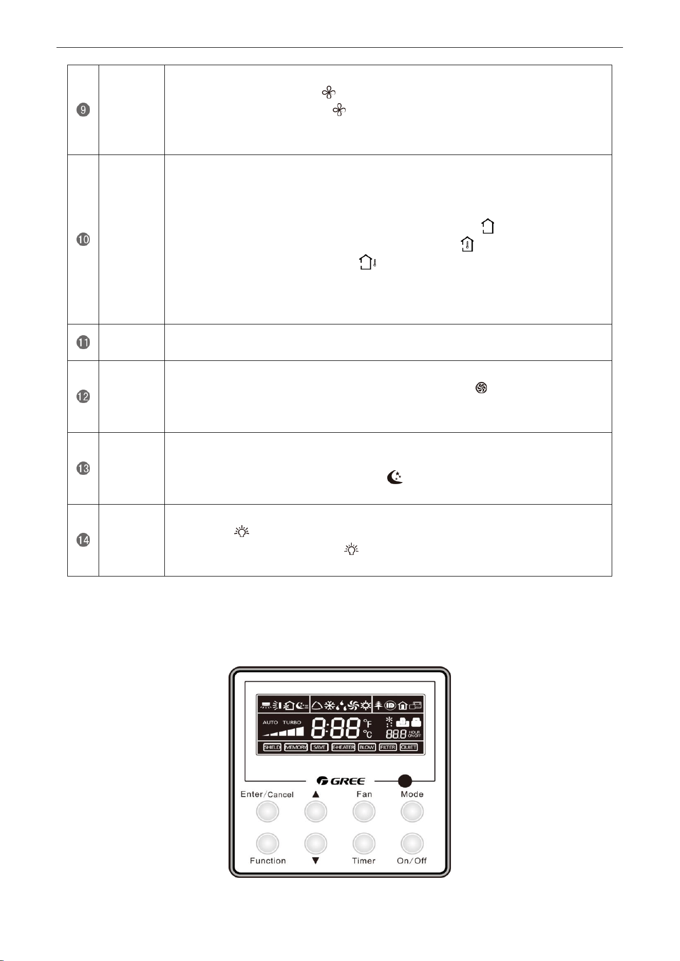
3 WIRED CONTROLLER
3.1 Display View
Figure 2-3-1 Appearance of wired controller
U-Match Series DC Inverter Service Manual
19
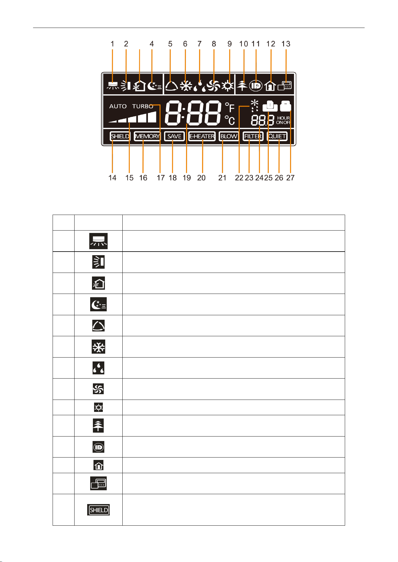
Figure 2-3-2 LCD display of wired controller
Table 2-3-1 Instruction to LCD Display
No.
Icons
Introduction
1
Left and right swing function
2
Up and down swing function
3
Air exchange function
4
Sleep function
5
Auto mode
6
COOL mode
7
DRY mode
8
FAN mode
9
HEAT mode
10
Health function
11
I-Demand function
12
Vacation function
13
Status display of master and slave wired controller
14
Shield function
The button operation, temperature setting, "On/Off" operation, "Mode" setting,
and "Save" setting are disabled.
U-Match Series DC Inverter Service Manual
20
15
Fan speed
16
Memory function
The unit will resume the original setting state after power recovery.
17
Turbo function
18
Energy-saving function
19
Ambient/setting temperature
20
Electric heater
21
Blow function
22
Defrosting function
23
Filter cleaning
24
Timer Setting
25
Keycard control / Detected status sensed by human body
26
Quiet function
27
Lock function
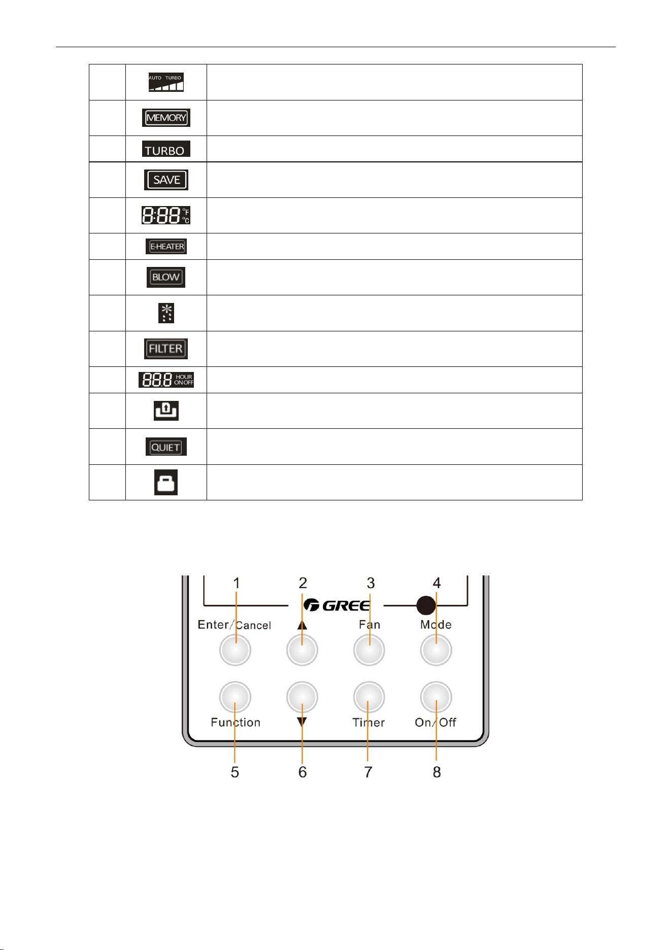
3.2 Operation View
3.2.1 Silk Screen of Buttons
Figure 2-3-3 Silk screen of buttons
U-Match Series DC Inverter Service Manual
21
3.2.2 Instruction to Function of Buttons
Table 2-3-2 Instruction to buttons of wired controller
No.
Description
Functions
1
Enter/Cancel
①. Function selection and canceling;
②. Press it for 5s to view the ambient temperature; press Mode button
to select viewing outdoor ambient temperature or indoor ambient
temperature.
2
▲
①. Running temperature setting range of indoor unit:
16~30℃(61~86℉);
②. Timer setting range: 0.5~24hr;
③. Setting of air function level;
④. Setting of energy-saving temperature;
⑤. Setting of cleaning class.
6
▼
3
Fan
Setting of high/medium high/medium/medium low/low/auto fan speed.
4
Mode
Setting of auto/cooling/heating/fan/dry mode of indoor unit.
5
Function
Switch over among these functions of swing/air/sleep/health/
I-Demand/out/turbo/save/e-heater/X-fan/clean/quiet.
7
Timer
Timer setting.
8
On/Off
Turn on/off indoor unit.
4 Mode
and
2 ▲
Memory function
Press Mode and ▲ buttons at the same time for 5s under off state of the
unit to enter/cancel memory function (If memory function is set, indoor
unit will resume original setting state after power failure and then power
recovery. If not, indoor unit is defaulted to be off after power recovery.
Ex-factory setting of memory function is on).
2 ▲
and
6 ▼
Lock
Upon startup of the unit without malfunction or under off state of the unit,
press ▲ and ▼ buttons at the same time for 5s to enter lock state. In this
case, any other buttons won‟t respond when pressing. Repress ▲ and ▼
buttons for 5s to quit lock state.
4 Mode
and
5 Function
Enquiry and
setting of address
of wired
controller
Under off state of the unit, press Mode and Function buttons at the same
time for 5s to set the address. (More details please refer to project
debugging)
5 Function
and
7 Timer
Setting of project
parameters
(More details
please refer to
the Notes)
Under off state of the unit, press Function and Timer buttons at the same
time for 5s to go to the debugging menu. Press Mode button to adjust the
setting items and press ▲ or ▼ buttons to set the actual value.
4 Mode
and
6 ▼
Switch between
Fahrenheit and
Centigrade
Under off state of the unit, press Mode and ▼ buttons at the same time
for 5s to switch between Fahrenheit and Centigrade.
5 Function
and
6 ▼
Viewing historical
malfunction
Continuously press Function and ▼ buttons for 5s to view historical
malfunction. Then press ▲ and ▼ buttons to adjust displayed content s.
The timer displaying position displays the sequence of malfunction and
the detailed error code. The 5th displayed malfunction is the last
malfunction.
1 Enter/Cancel
and
4 Mode
Setting of master
and slave wired
controller
Under off state of the unit, press Enter/Cancel and Mode buttons at the
same time for 5s to set master and slave wired controller. Press ▲ or ▼
button to adjust. (More details please refer to project debugging)
U-Match Series DC Inverter Service Manual
22
Note:
The following functions can be set through Function and Timer buttons: setting of ambient
temperature sensor, selecting three speeds in high speed and three speeds in low speed of indoor fan
motor, display setting of freeze protection error code, setting of cold air prevention and hot air hot
prevention function, setting of refrigerant-lacking protection function, selecting of blowing residual heat of
indoor unit, selecting of compressor electric heater mode, selecting of low-power consumption mode,
selecting door control function, selecting human sensitive function, long-distance monitoring, temperature
compensation value at the air return port.
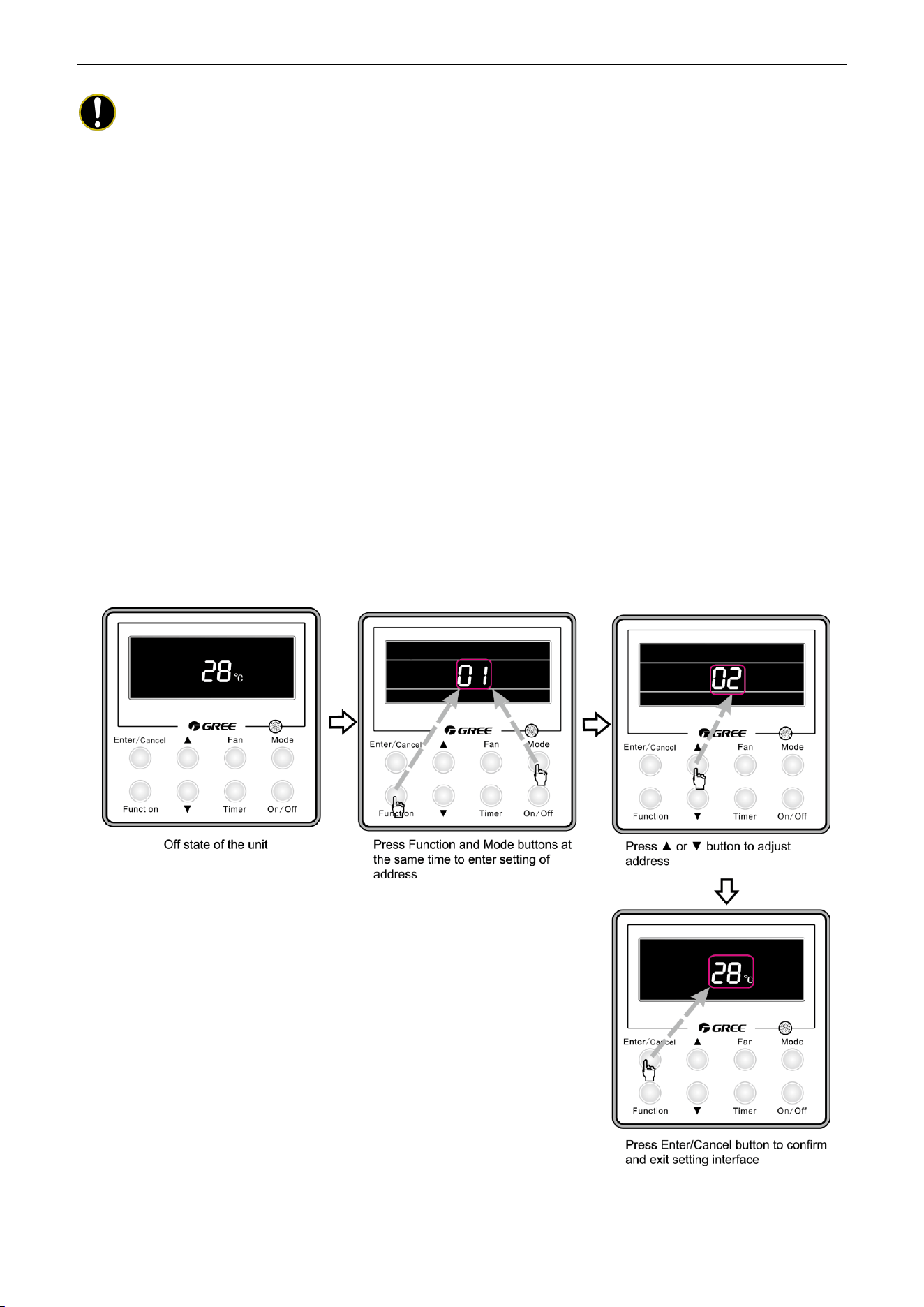
3.2.3 Setting of Wired Controller’s Address
3.2.3.1 Enquiry and Setting of Wired Controller’s Address
Under off state of the unit, press Function and Mode buttons at the same time for 5s to enter setting
interface of wired controller‟s address. In this case, LCD displays address number. Then press▲ or ▼
button to adjust address and then press Enter/Cancel button to confirm. The address setting is related to
the setting of Debugging Function 4.9.10. When the selection in 4.9.10 is 00, address of centralized
controller is to be set and the address setting range is 01~16; when the selection in 4.9.10 is 01, address of
long-distance monitor is to be set and the address setting range is 01~255.
Enquiry and setting of wired controller‟s address is shown as Figure 2-3-4 below:
Figure 2-3-4 Enquiry and setting of wired controller‟s address
U-Match Series DC Inverter Service Manual
23
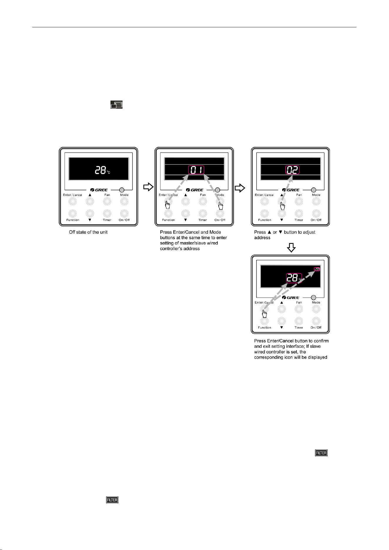
3.2.3.2 Setting of Master/Slave Wired Controller’s Address
Under off status of the unit, press Enter/Cancel and Mode buttons at the same time for 5s to go to the
enquiry and setting interface of master/slave wired controller. In this case, LCD displays wired controller‟s
address (01 for master wired controller and 02 for slave wired controller). Press ▲ or ▼ button to adjust
address of master/slave wired controller and then press Enter/Cancel button to confirm. If slave wired
controller is set, the icon will be displayed.
Note: If there is only one wired controller, it only can be set as the master; if there are two wired
controllers, one should be the master and the other should be the slave.
Setting of master/slave wired controller‟s address is shown as Figure 2-3-5 below:
Figure 2-3-5 Enquiry and setting of master/slave wired controller‟s address
4 OPERATION INSTRUCTION OF SPECIAL
FUNCTIONS
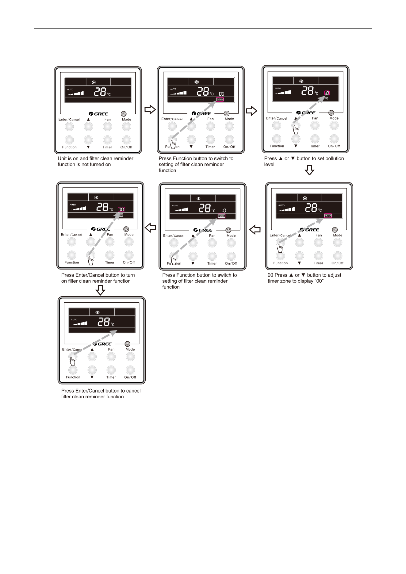
4.1 Setting of Filter Clean Reminder Function
When unit is on, press Function button to switch to filter clean reminder function. The icon will
blink and then enter setting of filter clean reminder function. Timer zone displays the set pollution level and
you can press ▲ or ▼ button to adjust the level. Then press Enter/Cancel button to turn on this function.
When filter clean reminder function is turned on, press Function button to switch to filter clean
reminder function. The icon will blink and press ▲ or ▼ button to adjust timer zone to display “00”.
Then press Enter/Cancel button to cancel this function.
U-Match Series DC Inverter Service Manual
24
Setting of filter clean reminder function is shown as Figure 2-4-1 below:
Figure 2-4-1 Setting of filter clean reminder function
When setting the filter clean reminder function, timer zone will display 2 digits, of which the former
indicates the pollution degree of operating place and the latter indicates the accumulated operating time of
indoor unit. There are 4 types of situations:
(1) Clean Reminder is off (Timer zone shows “00“);
(2) Slight pollution: the former digit in timer zone shows 1 while the latter one shows 0, which
indicates the accumulated operating time is 5500hr. Each time the latter digit increases 1, the
accumulated operating time increases 500hr. When it reaches 9, it means the accumulated
operating time is 10000hr;
(3) Medium pollution: the former digit in timer zone shows 2 while the latter one shows 0, which
indicates the accumulated operating time is 1400hr. Each time the latter digit increases 1, the
U-Match Series DC Inverter Service Manual
25
accumulated operating time increases 400hr. When it reaches 9, it means the accumulated
operating time is 5000hr;
(4) Heavy pollution: the former digit in timer zone shows 3 while the latter one shows 0, which
indicates the accumulated operating time is 100hr. Each time the latter digit increases 1, the
accumulated operating time increases 100hr. When it reaches 9, it means the accumulated
operating time is 1000hr;
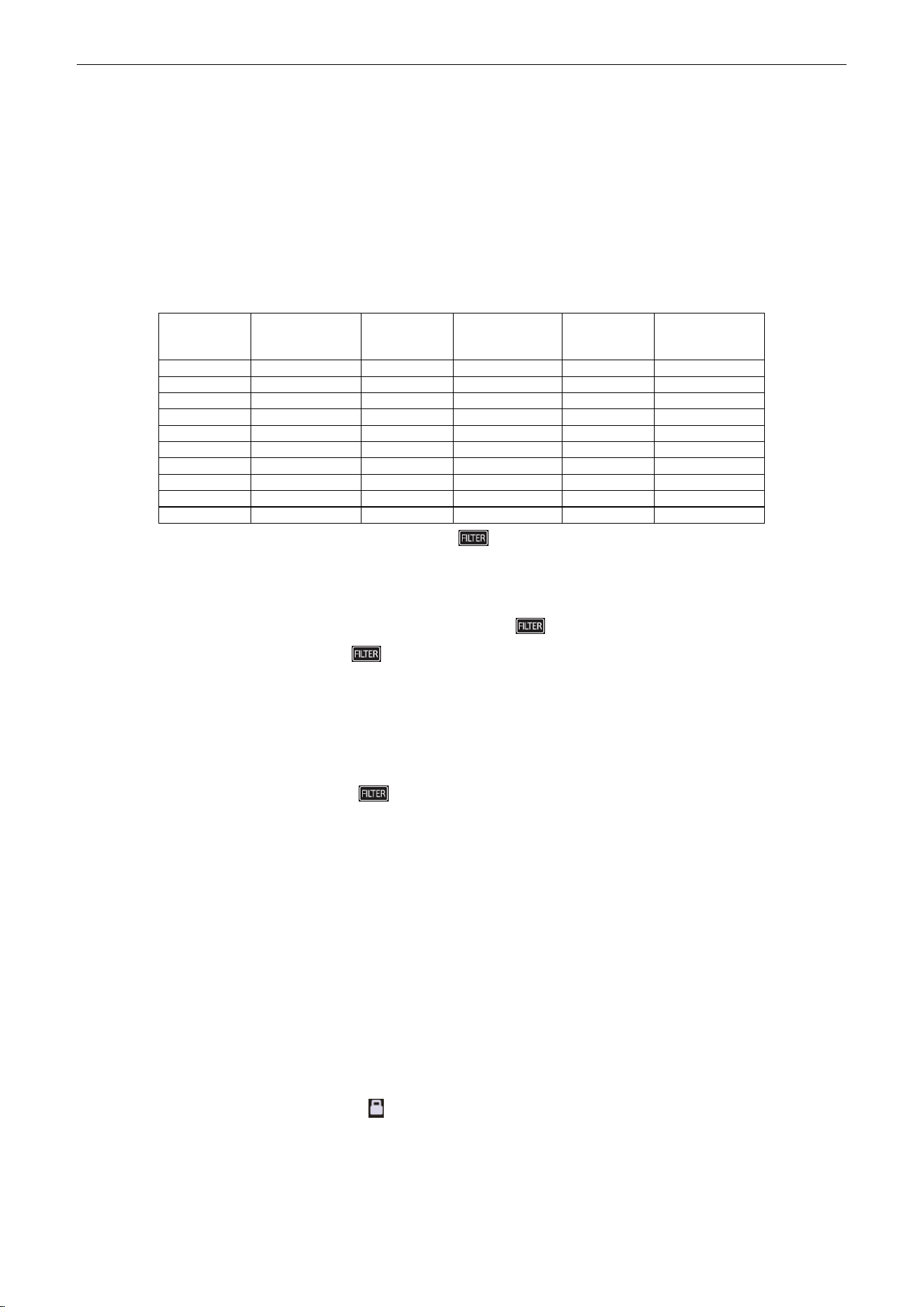
The detailed pollution level and the corresponding time is as shown in Table 2-4-1 below:
Table 2-4-1 Pollution level and corresponding time
Pollution
level
Accumulated
operating time
(hour)
Pollution
level
Accumulated
operating time
(hour)
Pollution
level
Accumulated
operating time
(hour)
10
5500
20
1400
30
100
11
6000
21
1800
31
200
12
6500
22
2200
32
300
13
7000
23
2600
33
400
14
7500
24
3000
34
500
15
8000
25
3400
35
600
16
8500
26
3800
36
700
17
9000
27
4200
37
800
18
9500
28
4600
38
900
19
10000
29
5000
39
1000
If filter clean reminder function is turned on, the icon will be on.
(1) If cleaning time is not reached, no mater the setting is changed or not, the accumulated operating
time won‟t be recalculated when pressing Enter/Cancel button;
(2) If cleaning time is reached, in unit on or off state, will blink every 0.5s for reminder. Press
Function button to switch to icon and press ▲ and ▼ button to adjust the level. Then press
Enter/Cancel button, so the accumulated operating time won‟t be cleared (If the adjusted level is
higher than the present accumulated operating time, the icon won‟t blink any more; if the adjusted
level is lower than the present accumulated operating time, the icon will go on blinking).
(3) The only way to cancel filter clean reminder function is to press Function button to switch to filter
clean reminder function. The icon will blink and press ▲ or ▼ button to adjust timer zone to
display “00”. In this case, the accumulated operating time will be cleared.
4.2 Low Temperature Drying Function
Under dry mode and when set temperature is 16℃(61℉), continuously press ▼ button for twice and
then the set temperature will be 12℃ (54℉). In this case, the unit will enter low temperature drying
function.
When low temperature drying function is turned on, press ▲ button or Mode button to exit low
temperature drying function.
4.3 Lock Function
When unit is turned on normally or turned off, pressing ▲ and ▼ buttons at the same time for 5s will
turn on Lock function. LCD will display . Pressing ▲ and ▼ buttons at the same time for 5s to turn off
this function.
When Lock function is turned on, any other buttons won‟t respond when pressing. The function can be
memorized after power failure and then power recovery.
U-Match Series DC Inverter Service Manual
26
4.4 Memory Function
Press Mode and ▲ buttons at the same time for 5s under off state of the unit to turn on or cancel
memory function. If memory function is set, is displayed. If not, indoor unit is defaulted to be off
after power recovery.
If memory function is set, indoor unit will resume original setting state after power failure and then
power recovery.
Note:
If cut off power with 5s after memorized content is changed, the memorized content may be
abnormal. Do not cut off power within 5s after memorized content is changed.
4.5 Door Control Function/Human Sensitive Function
Door control function or human sensitive function can be selected (More details please refer to
Debugging Function). These two functions can‟t be turned on at the same time.
When door control function is selected, the wired controller will work when the room card is inserted
and stop working when the room card is not inserted; when human sensitive function is selected, the wired
controller will work when it senses there is somebody in the room and stop working when it senses there is
nobody in the room. When the door control function senses the room card is not inserted or human
sensitive function senses there is nobody in the room, the wired controller will display icon.
Notes:
① In long-distance monitoring or centralized control, no matter the room card is inserted or not,
the ON/OFF of unit can be controlled. If long-distance monitoring or centralized control
information is received when the room card is not inserted, icon is cleared. When the
card is reinserted, door control function is judged to be turned on. If long-distance monitoring
or centralized control information is received when the room card is inserted, it will keep the
original status.
② The unit can not be controlled by buttons when the card is not inserted.
③ When door control function and human sensitive function have been set at the same time, it
is defaulted that door control function is valid and human sensitive function is invalid.
4.6 Switch between Fahrenheit and Centigrade
Under off state of the unit, press Mode and ▼ buttons at the same time for 5s to switch between
Fahrenheit and Centigrade.
4.7 Enquiry of Ambient Temperature
Under off or on state of the unit, press it for 5s to view the ambient temperature. In this case, timer
zone displays ambient temperature type 01 or 02. Ambient temperature zone displays the corresponding
temperature of that type. 01 stands for outdoor ambient temperature and 02 stands for the indoor ambient
temperature after compensation. Press Mode button to switch between 01 and 02. Pressing other buttons
except Mode button or receiving remote control signal will exit enquiry state. If there is no operation within
20s will also exit enquiry state.

U-Match Series DC Inverter Service Manual
27
Notes:
① If the unit is not connected to outdoor ambient temperature sensor, display of outdoor
ambient temperature will be shielding after energizing for 12hr.
② If there is malfunction of outdoor ambient temperature sensor, display of outdoor ambient
temperature will be shielding after energizing for 12hr.
4.8 Enquiry of Historical Malfunction
Under off or on state of the unit, continuously press Function and ▼ buttons for 5s to view historical
malfunction.
In enquiry state, set temperature displaying zone displays “00”. Press ▲ and ▼ buttons to view the 5
malfunctions happened recently. The timer displaying position displays the detailed error code. The 5th
displayed malfunction is the last malfunction.
4.9 Debugging Function
Under off state of the unit, press Function and Timer buttons at the same time for 5s to go to the
debugging menu. Press Mode button to adjust the setting items and press ▲ or ▼ button to set the actual
value.
4.9.1 Setting ambient temperature sensor (dual ambient temperature
sensors function)
Under debugging state, press Mode button to adjust to “00” in temperature displaying zone. Timer
zone displays setting state and press ▲ or ▼ button to adjust. There are 3 selections:
(1) The ambient temperature at air return is set as indoor ambient temperature (timer zone displays
01).
(2) The temperature at wired controller is set as indoor ambient temperature (timer zone displays 02).
(3) Select the temperature sensor at air return in cooling, dry and fan mode; select the temperature
sensor at wired controller in heating and auto mode.
4.9.2 Selecting three speeds in high speed and three speeds in low speed
of indoor fan motor
Under debugging state, press Mode button to adjust to “01” in temperature displaying zone. Timer
zone displays setting state and press ▲ or ▼ button to adjust. There are 2 selections:
(1) Three speeds in low speed (LCD displays 01)
(2) Three speeds in high speed (LCD displays 02)
Three speeds in low speed include high, medium and low speeds; three speeds in high speed include
super high, high and medium speed.
Note:
For this series, this function is invalid.
U-Match Series DC Inverter Service Manual
28
4.9.3 Displaying setting of freeze protection error code
Under debugging state, press Mode button to adjust to “02” in temperature displaying zone. Timer
zone displays setting state and press ▲ or ▼ button to adjust. There are 2 selections:
(1) Displayed (LCD displays 01)
(2) Not displayed (LCD displays 02)
It is defaulted to be not displayed for export unit and be displayed for domestic unit.
4.9.4 Setting refrigerant lacking protection function
Under debugging state, press Mode button to adjust to “04” in temperature displaying zone. Timer
zone displays setting state and press ▲ or ▼ button to adjust. There are 2 selections:
(1) With refrigerant lacking protection function (LCD displays 01)
(2) Without refrigerant lacking protection function (LCD displays 02)
4.9.5 Selecting blowing residual heating of indoor unit
Under debugging state, press Mode button to adjust to “05” in temperature displaying zone. Timer
zone displays setting state and press ▲ or ▼ button to adjust. There are 2 selections:
(1) Mode 1 (LCD displays 00)
(2) Mode 2 (LCD displays 01)
Note:
Blowing residual heating of indoor unit
Mode 1: Unit stops when reaching temperature point and indoor fan motor does not stop in cooling
mode; after unit stops when reaching temperature point in heating mode, duct type unit and floor ceiling
unit blow residual heat for 60s and then stop indoor unit, while cassette type unit always operates in low fan
speed and blows residual heat for 60s when there is malfunction.
Mode 2: After unit stops when reaching temperature point, the indoor fan motor stops operation with a
10s delay no matter in cooling mode or in heating mode.
4.9.6 Mode selecting of compressor electric heating belt
Under debugging state, press Mode button to adjust to “06” in temperature displaying zone. Timer
zone displays setting state and press ▲ or ▼ button to adjust. There are 2 selections:
(1) Mode 1 (LCD displays 00)
(2) Mode 2 (LCD displays 01)
Notes:
① Mode 1: Compressor electric heating belt starts when outdoor ambient temperature is below
35
℃
(95
℉
) and stops when outdoor ambient temperature is above 37
℃
(99
℉
). When
outdoor ambient temperature is within 35
℃
(95
℉
)~ 37
℃
(99
℉
), the belt will keep its
previous operation state.
② Mode 2: Compressor electric heating belt starts when outdoor ambient temperature is below
-2 (28
℉
) and stops when outdoor ambient temperature is above 0
℃
(32
℉
). When outdoor
ambient temperature is within -2
℃
(28
℉
)~0
℃
(32
℉
), the belt will keep its previous

U-Match Series DC Inverter Service Manual
29
operation state.
4.9.7 Selecting low-power consumption mode
Under debugging state, press Mode button to adjust to “07” in temperature displaying zone. Timer
zone displays setting state and press ▲ or ▼ button to adjust. There are 2 selections:
(1) With low-power consumption mode (LCD displays 00)
(2) Without low-power consumption mode (LCD displays 01)
4.9.8 Selecting door control function
Under debugging state, press Mode button to adjust to “08” in temperature displaying zone. Timer
zone displays setting state and press ▲ or ▼ button to adjust. There are 2 selections:
(1) Without door control function (LCD displays 00)
(2) With door control function (LCD displays 01)
4.9.9 Selecting human sensitive function
Under debugging state, press Mode button to adjust to “09” in temperature displaying zone. Timer
zone displays setting state and press ▲ or ▼ button to adjust. There are 2 selections:
(1) Without human sensitive function (LCD displays 00)
(2) With human sensitive function (LCD displays 00)
4.9.10 Selecting long-distance monitoring or centralized controller
Under debugging state, press Mode button to adjust to “10” in temperature displaying zone. Timer
zone displays setting state and press ▲ or ▼ button to adjust. There are 2 selections:
(1) Centralized controller (LCD displays 00)
(2) Long-distance monitoring (LCD displays 01)
4.9.11 Selecting fan mode of indoor fan motor
Under debugging state, press Mode button to adjust to “11” in temperature displaying zone. Timer
zone displays setting state and press ▲ or ▼ button to adjust. There are 4 selections:
(1) P3 (LCD displays 03)
(2) P4 (LCD displays 04)
(3) P5 (LCD displays 05)
(4) P6 (LCD displays 06)
(5) P7 (LCD displays 07)
Note:
You can select P03, P04, P05, P06, P07 in fan mode of indoor fan motor, which means
different fan mode combinations are corresponding to different static pressure. Ex-factory defaulted mode
is P05. You can set the mode through wired controller. S01, S02, S03……S12, S13 means the rotation
speed of indoor unit is from low to high.
U-Match Series DC Inverter Service Manual
30
Table 2-4-2 Combination relationship of P03, P04, P05, P06, P07
Static
pressure
selection
Super
high
speed
High
speed
Medium
high speed
Mediu
m
speed
Medium
low speed
Low
speed
Quiet
R1
speed
Quiet
R2
speed
Quiet
R3
speed
P03
S09
S08
S07
S06
S05
S04
S03
S02
S01
P04
S10
S09
S08
S07
S06
S05
S04
S03
S02
P05
S11
S10
S09
S08
S07
S06
S05
S04
S03
P06
S12
S11
S10
S09
S08
S07
S06
S05
S04
P07
S13
S12
S11
S10
S09
S08
S07
S06
S05
4.9.12 Selecting compensation of temperature sensor at air return
Under debugging state, press Mode button to adjust to “12” in temperature displaying zone. Timer
zone displays setting state and press ▲ or ▼ button to adjust. There are 16 selections:
(1) Compensate 0
℃
(32
℉
) (LCD displays 00)
(2) Compensate 1
℃
(34
℉
) (LCD displays 01)
(3) Compensate 2
℃
(36
℉
) (LCD displays 02)
(4) Compensate 3
℃
(37
℉
) (LCD displays 03)
(5) Compensate 4
℃
(39
℉
) (LCD displays 04)
(6) Compensate 5
℃
(41
℉
) (LCD displays 05)
(7) Compensate 6
℃
(43
℉
) (LCD displays 06)
(8) Compensate 7
℃
(45
℉
) (LCD displays 07)
(9) Compensate 8
℃
(46
℉
) (LCD displays 08)
(10) Compensate 9
℃
(48
℉
) (LCD displays 09)
(11) Compensate 10
℃
(50
℉
) (LCD displays 10)
(12) Compensate 11
℃
(52
℉
) (LCD displays 11)
(13) Compensate 12
℃
(54
℉
) (LCD displays 12)
(14) Compensate 13
℃
(55
℉
) (LCD displays 13)
(15) Compensate 14
℃
(57
℉
) (LCD displays 14)
(16) Compensate 15
℃
(59
℉
) (LCD displays 15)
Note:
Indoor ambient temperature compensation can be set through wired controller (E.g. If 02 is
selected, it indicates the compensation temperature is 2℃ (36℉). If the indoor ambient temperature
detected by the temperature sensor at air return is 29℃ (84℉), the ambient temperature after
compensation is 29℃ (84℉)-2℃ (36℉)=27℃ (81℉)).
After finishing setting, press Enter/Cancel button to save and exit setting. After entering this interface,
the system will exit this menu if there is no operation on the button within 20s. Normal off state interface will
be displayed and present setting will not be saved.
U-Match Series DC Inverter Service Manual
31
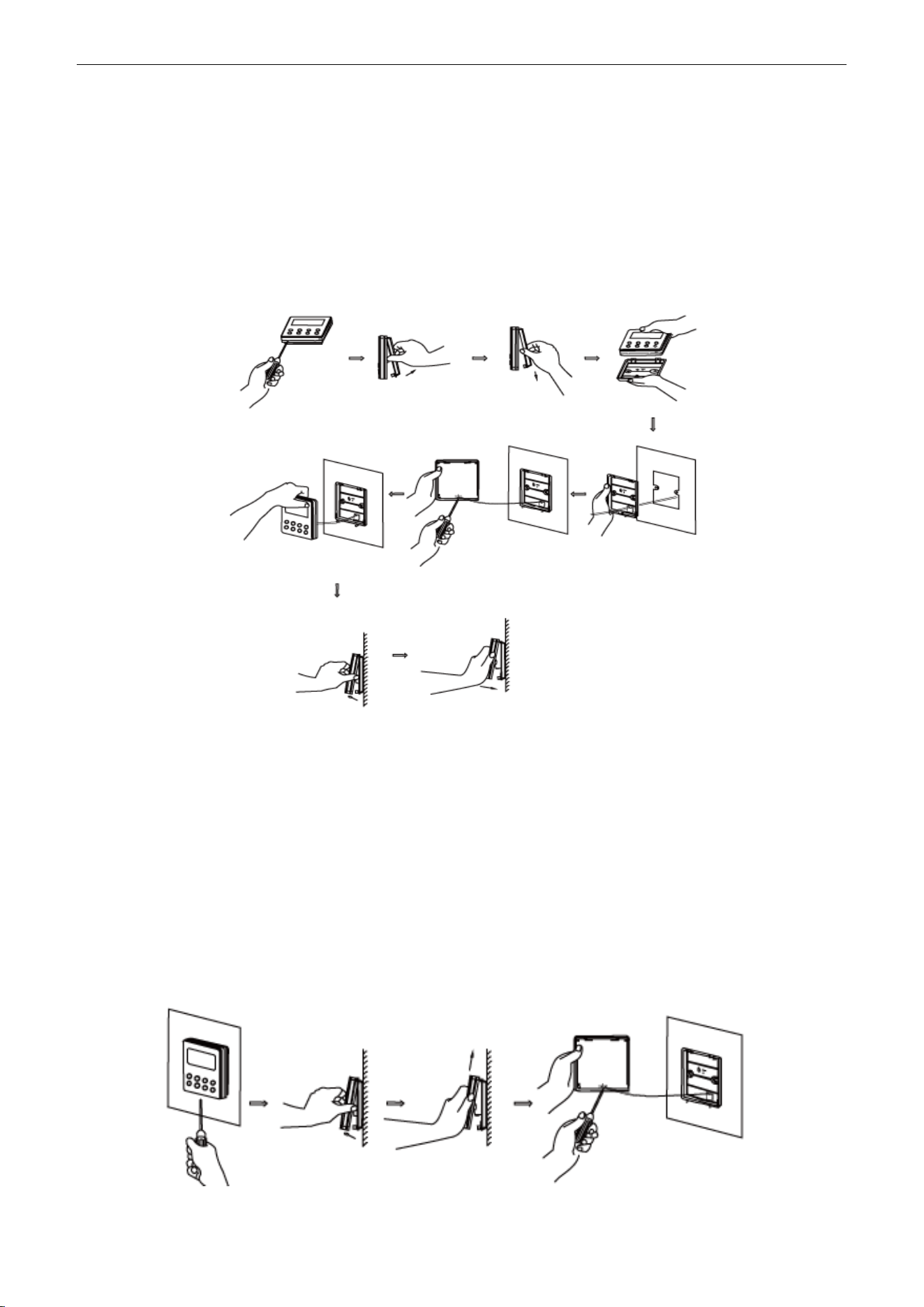
5 INSTALLATION OF WIRED CONTROLLER
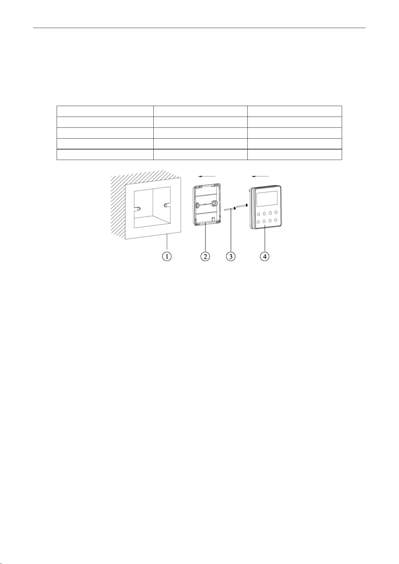
5.1 Standard Accessories
Table 2-5-1 Standard Accessories of Wired Controller
Description
Quantity
Note
Socket base box installed in the wall
1
No.1 in Figure 2-5-1
Base plate of wired controller
1
No.2 in Figure 2-5-1
Screw M4×25
2
No.3 in Figure 2-5-1
Panel of wired controller
1
No.4 in Figure 2-5-1
Figure 2-5-1
5.2 Installation Position and Requirement
(1) Prohibit installing the wired controller at the misty place or the place with direct sunlight.
(2) Prohibit installing the wired controller at the place near high temperature objects or
water-splashing places.
(3) Prohibit installing the wired controller at the place where faces forward to the window, to avoid
interference of another remote controller from neighborhood.
(4) Cut off the power of heavy current wire in the installation hole of the wall. All power should be cut
off during installation.
(5) In order to avoid abnormal operation due to electromagnetic interference, etc., pay attention to the
following notes during connecting wires:
1) Make sure the tie-in interface of communication wire is correct, otherwise it may lead to
communication malfunction.
2) The signal wires and communication wires of wired controller should be separated from power
cord and connection wire between indoor unit and outdoor unit.
3) If the air conditioner is installed at the strong electromagnetic interference place, signal wire
and communication wire of wired controller must use shielding twisted wire.
U-Match Series DC Inverter Service Manual
32
5.3 Installation of Wired Controller
Firstly, the selection and connection way of wired controller‟s signal wire are as below:
(1) Choose suitable signal wire: 2-core signal wire (wire diameter
≥
0.75mm2 (AWG18), wire
length<30m (98-2/5ft) and the recommended length is 8m (26-1/4ft).
(2) Make sure the power of indoor unit is cut off; fix the signal wire of wired controller on the wiring
board for wired controller of indoor unit with screws; make sure the signal wire is solid.
Then, the detailed installation procedures of wired controller are as shown in Figure 2-5-2:
Figure 2-5-2 Installation of wired controller
Brief instructions of installation procedure:
(1) Pull out the 2-core signal wire in the installation hole of the wall and then let this wire go through
the hole at the back of wired controller‟s base plate.
(2) Fix the base plate and installation hole of the wall together with screw M4×25mm (3/16×1inch).
(3) Fix the above mentioned 2-core signal wire on the copper insert X1 and X2 with the equipped
screws of wired controller.
(4) Fasten the wired controller‟s panel with its base plate together.
5.4 Removal of Wired Controller
Figure 2-5-3 Removal of wired controller
U-Match Series DC Inverter Service Manual
33
6 TROUBLESHOOTING
6.1 Display of Error Code
Table 2-6-1 Error Code List
Error Code
Error
E1
Compressor high pressure protection
E2
Freeze protection
E3
Compressor low pressure protection, refrigerant lacking protection, refrigerant
recycling mode
E4
Compressor high discharge temperature protection
E6
Communication malfunction
E8
Malfunction of indoor fan motor
E9
Full water protection
F0
Malfunction of indoor ambient temperature sensor
F1
Malfunction of evaporator temperature sensor
F2
Malfunction of condenser temperature sensor
F3
Malfunction of outdoor ambient temperature sensor
F4
Malfunction of discharge temperature sensor
F5
Malfunction wired controller temperature sensor
C5
Wong dial switch of capacity
EE
Malfunction of outdoor main control memory chip
PF
Malfunction of electric box sensor
H3
Compressor overload protection
H4
Overload protection
H5
IPM protection
H6
Malfunction of DC fan motor
H7
Drive desynchronizing protection
HC
PFC protection
L1
Malfunction of humidity sensor
Lc
Start-up failure
Ld
Compressor phase protection
LF
Power protection
Lp
Models of indoor unit and outdoor unit do not match with each other
U7
Direction changing malfunction of 4-way valve
P0
Drive reset protection
P5
Overcurrent protection
P6
Communication malfunction between main control and drive
P7
Malfunction of drive module sensor
P8
High temperature protection of drive module
P9
Zero-cross protection
PA
AC current protection
PC
Malfunction of drive current
Pd
Sensor connection protection
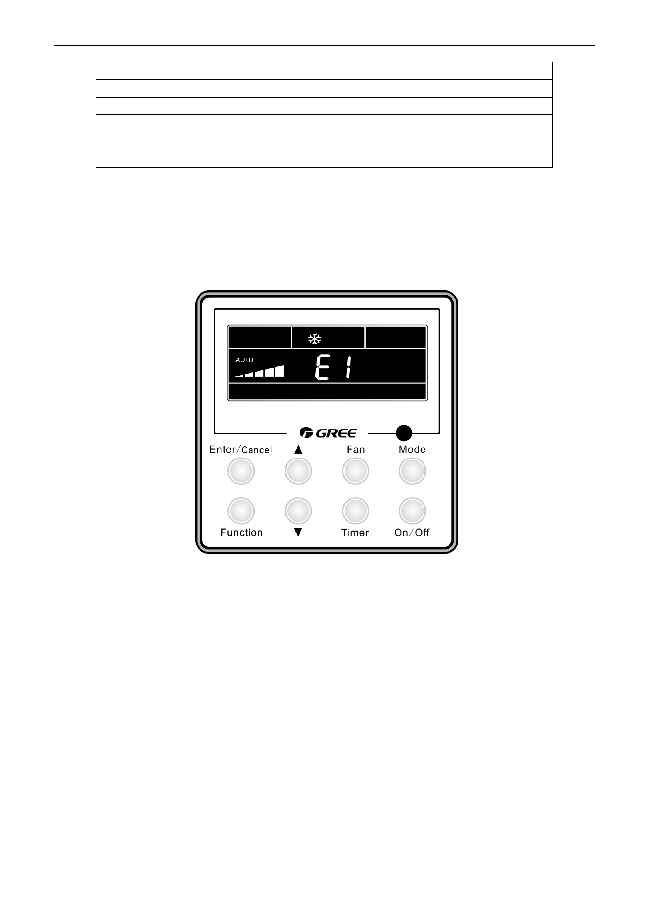
U-Match Series DC Inverter Service Manual
34
When there is a malfunction during operation, error will be displayed on the temperature displaying
zone of LCD. When several malfunctions occur at the same time, these error codes will be displayed
circularly.
When there is a malfunction, please turn off the unit and ask the professional for maintenance.
For example, E1 means high pressure protection during operation.
Figure 2-6-1
7 CENTRALIZED CONTROLLER
7.1 Smart Zone Controller
7.1.1 Function
The smart zone controller can directly control up to 16 sets of indoor units in a control network and is
available to check the running status of any unit through the LCD, including running mode, timer, fan speed,
centralized control and shielding setting etc.
PE
Temperature excursion protection
PL
Low voltage protection of bus bar
PH
High voltage protection of bus bar
PU
Charging circuit malfunction
PP
Abnormity of input voltage
ee
Malfunction of outdoor drive memory chip
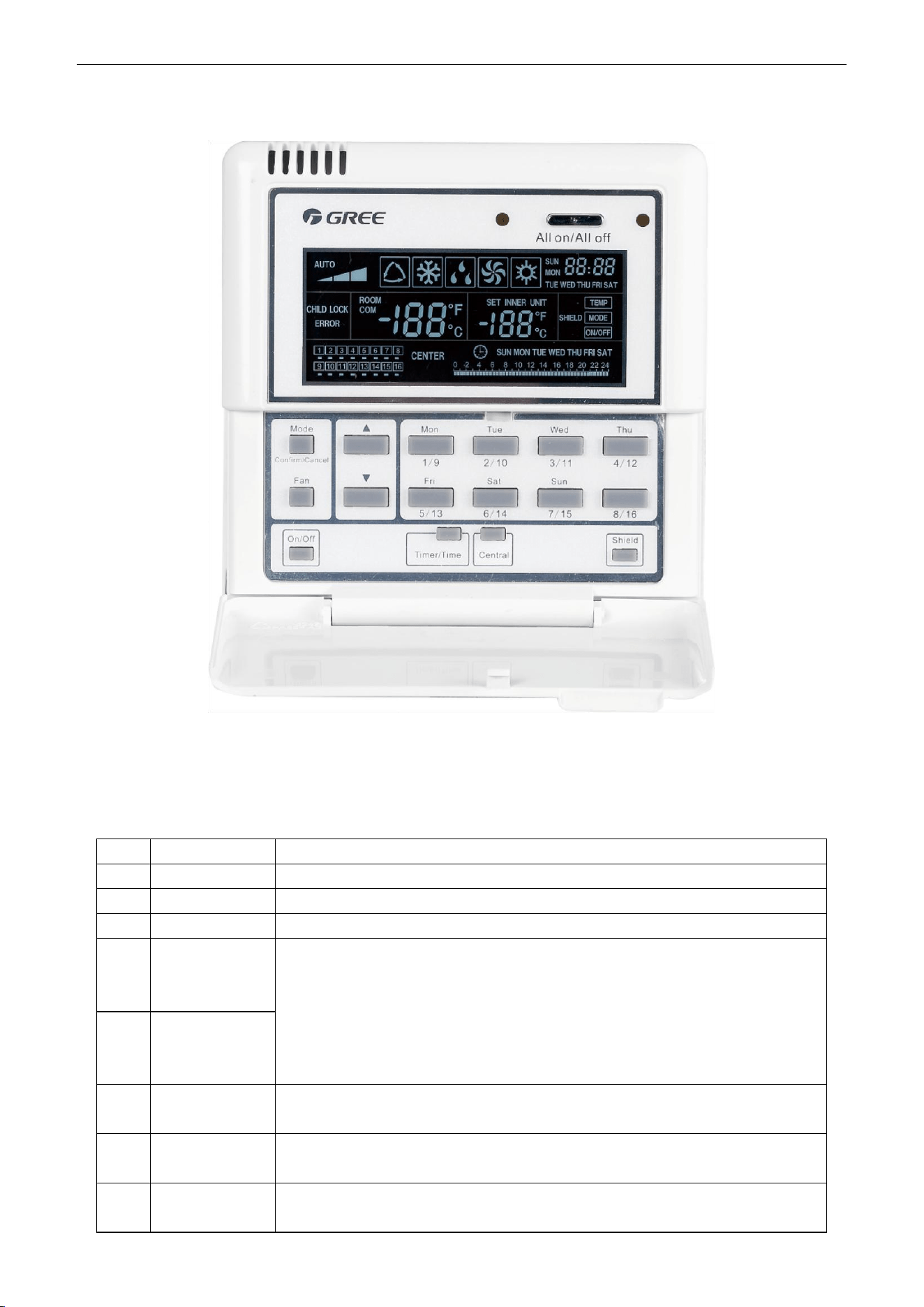
U-Match Series DC Inverter Service Manual
35
7.1.2 Outline Drawing of Press Buttons
Figure 2-7-1
7.1.3 Functions of Press Buttons
Table 2-7-1 Functions of Press Buttons
No.
Name
Function Description
1
Mode
It is used for the switchover among different modes.
2
Fan
It is used to set the fan speed, high, medium, low or auto.
3
On/Off
It is used to set the on/off status of the indoor unit.
4
▲
①. Under the single/centralized control status: It is used to set the running
temperature of the indoor unit with max.30°C (86℉) anmin.16°C (61℉);
②. Under the timing setting status: It is used to set the timing period with max.24
hours and min.0 hour;
③. Under the clock setting status: it is used to set the hour (max.:23, min.: 0) and
minute (max.:59, min.: 0) of the clock.
5
▼
6
Mon
1/9
It is used for the switchover between unit 1 and unit 9;
Under the timing or clock setting status, it indicates Monday.
7
Tue
2/10
It is used for the switchover between unit 2 and unit 10;
Under the timing or clock setting status, it indicates Tuesday.
8
Wed
3/11
It is used for the switchover between unit 3 and unit 11;
Under the timing or clock setting status, it indicates Wednesday.
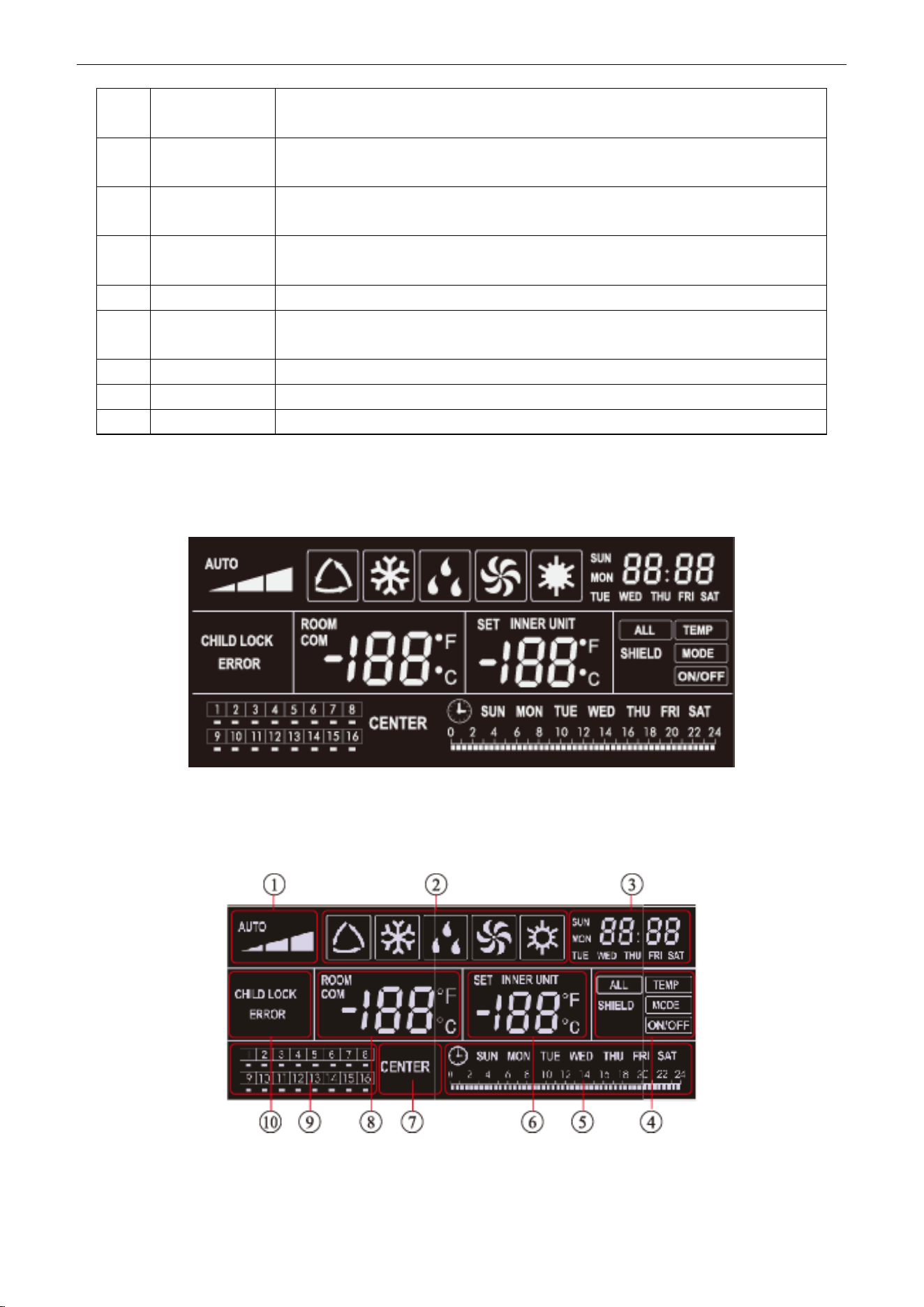
U-Match Series DC Inverter Service Manual
36
9
Thu
4/12
It is used for the switchover between unit 4and unit 12;
Under the timing or clock setting status, it indicates Thursday.
10
Fri
5/13
It is used for the switchover between unit 5and unit 13;
Under the timing or clock setting status, it indicates Friday.
11
Sat
6/14
It is used for the switchover between unit 6 and unit 14;
Under the timing or clock setting status, it indicates Saturday.
12
Sun
7/15
It is used for the switchover between unit 7 and unit 15;
Under the timing or clock setting status, it indicates Sunday.
13
8/16
It is used for the switchover between unit 8 and unit 16.
14
Timer/Time
It is used to set the timing or on/off time of the selected indoor unit as well as to set
the clock of the system.
15
Central
It is used for the switchover between single and centralized control modes.
16
Shield
It is used to deactivate some or all functions of a single or a group the indoor unit(s).
17
All on/off
It is used to start/stop all indoor units.
7.1.4 LCD of the Controller
7.1.4.1 Outline Drawing of the LCD
Figure 2-7-2
7.1.4.2 Introduction to Symbols on the LCD
Figure 2-7-3
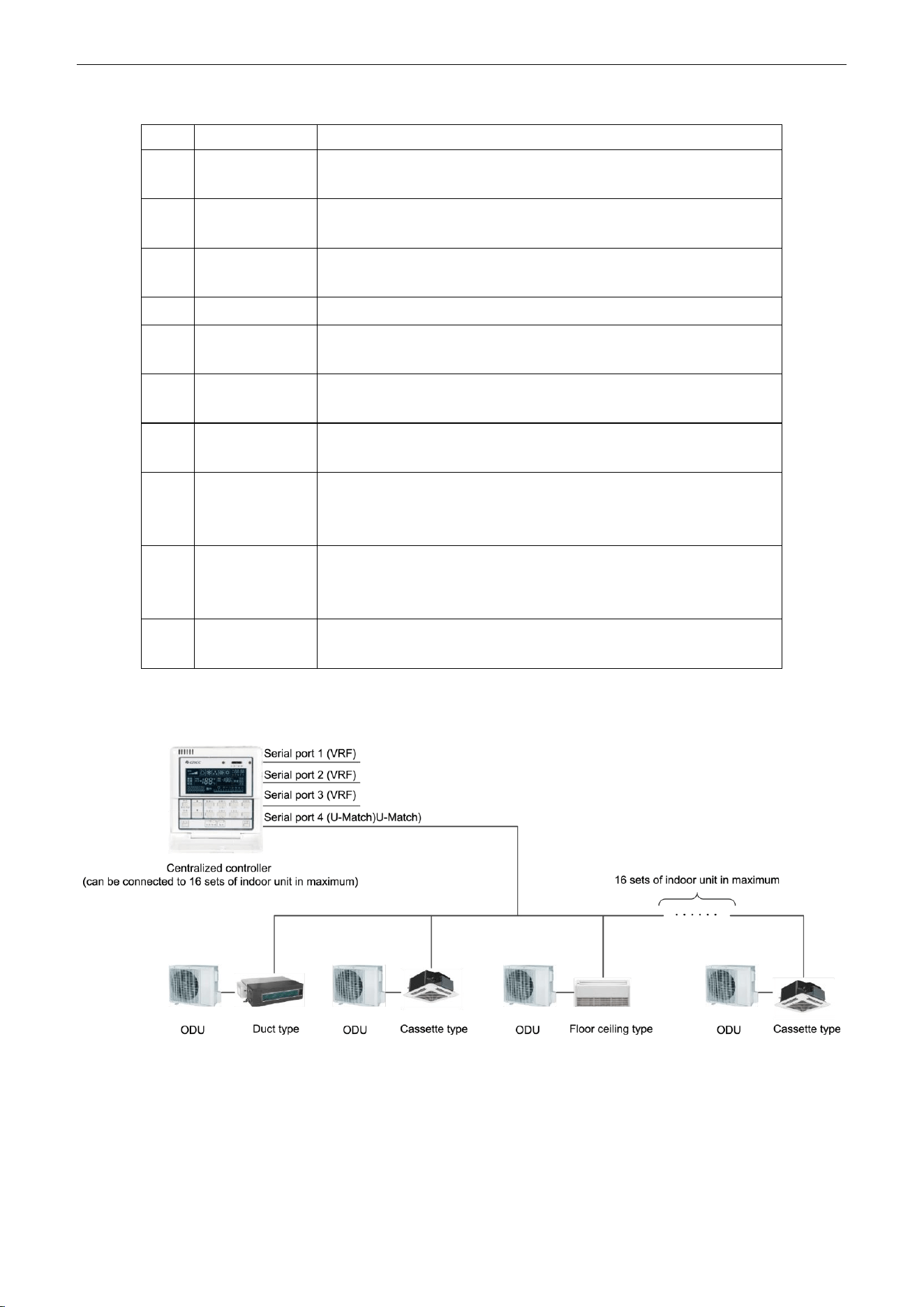
U-Match Series DC Inverter Service Manual
37
Table 2-7-2 Introduction to the Symbols on the LCD
No.
Name
Description
1
Fan speed
It displays the fan speed of the indoor unit, high, medium, low and
auto.
2
Running mode
It displays the running mode of the indoor unit, auto, cool, dry, fan and
heat.
3
System clock
It displays the current time (hour and minute) in 24-hour time system
and also the week day.
4
Shield
It displays the shield status, “ALL‟, “TEMP”, “MODE” and „ On/Off”.
5
Weekly timer
It displays the timing period (unit: 0.5 hour) which will circulate every
week.
6
Set temperature
Indoor unit code
It displays the set temperature, indoor unit code (01-16), and symbols
of Celsius and Fahrenheit scale.
7
Control mode
It displays “CENTER” under the centralized control mode and no
display under the single control mode.
8
Ambient
temperature
Serial port
It displays the ambient temperature, serial port as well as symbols of
Celsius and Fahrenheit scale.
9
Indoor unit code
On/off status
Numbers indicate the indoor unit codes which will be displayed when
the corresponding indoor unit is online; “” indicates the on/off status of
the indoor unit, its flashing for “on” or else for “off”
10
Error
Child lock
It displays the error codes when some error(s) arises and also “CHILD
LOCK” when this function is activated.
7.1.4.3 Network Topology
Network Connection of the Smart Zone Controller
Figure 2-7-4
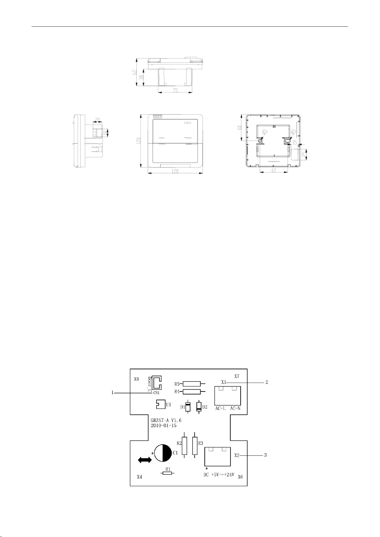
U-Match Series DC Inverter Service Manual
38
7.1.4.4 Dimensions
Figure 2-7-5
7.2 Additional Special Functions
7.2.1 Door control function
Door control function is available for this series. In order to achieve this function, please select the
door control accessories from Gree.
(1) Interface instructions
1) The interface printing is DOOR-C and the type is B2B-XH-B. The wires of door control
accessories must be connected to this interface;
2) Electrical characteristic: none;
3) Working principle: when the card is inserted, this interface is short-circuited; when the card is
not inserted, this interface is cut off;
Connect the door control detection port of indoor main board with the interface of door control board
(CN1 in the following Figure); connect the door control signal to the door control signal input port (X1 and
X2 in the following Figure). X1 is AC 220V signal input and X2 is DC +5V to 24V. You can only choose X1
or X2. Definition of interface is as shown in Figure below:
Figure 2-7-6 Illustration of door control port
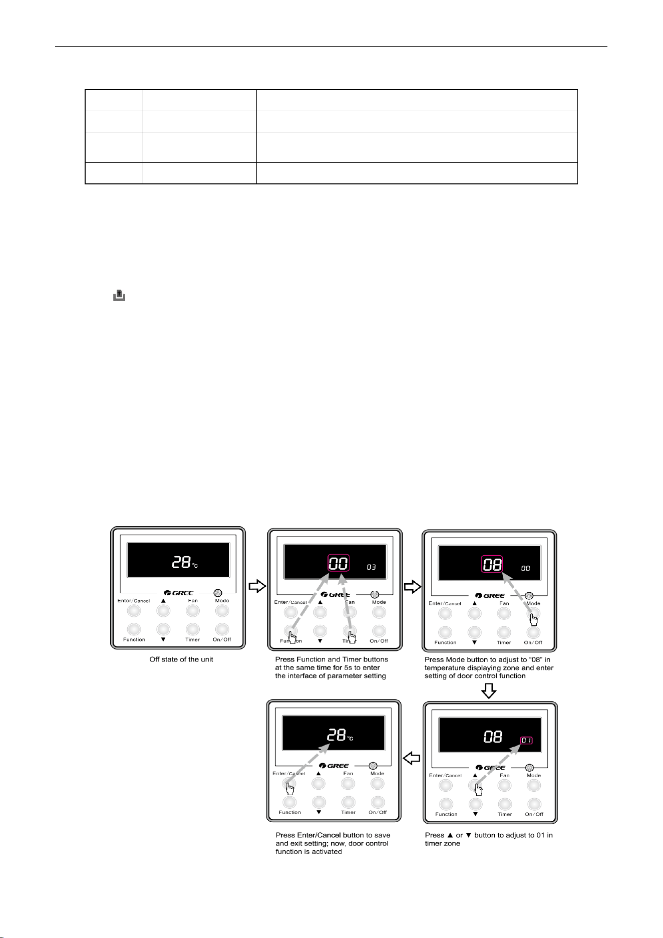
U-Match Series DC Inverter Service Manual
39
Table 2-7-3 Door control wiring port
No.
Terminal name
Terminal instruction
1
CN1
CN1 wiring terminal and door control interface of indoor main board
2
X1(AC-L, AC-N)
X1(AC-L, AC-N) wiring terminal, connected to door control input
signal, rated voltage 220V.
3
X2
X2 wiring terminal, connected to door control input signal
(2) Function instructions:
In order to achieve this function, set it through wired controller and refer to the following operation
method. It is defaulted that this function is not activated; if this function is set and door control accessories
are connected, the unit will control the ON/OFF of unit according to the card state detected by door control
detection board. When the card is not connected, the unit will turn to standby state. If the unit is with wired
controller, icon will be displayed on the wired controller.
If the unit is without wired controller, there will be no display. The unit will control the ON/OFF of unit
according to the detected information.
(3) Setting method:
Under off state of the unit, press Function and Timer buttons at the same time for 5s to go to the
debugging menu. Press Mode button to adjust to “08” in temperature displaying zone. Timer zone displays
setting state and press ▲ or ▼ button to adjust. There are 2 selections:
1) Without door control function (LCD displays 00)
2) With door control function (LCD displays 01)
Choose the second selection and then press Enter/Cancel button to save and exit setting. Now, door
control function is activated. The unit will memorize this setting status. The setting value will be memorized
after power failure. The detailed setting is as shown in the Figure below:
Figure 2-7-7
U-Match Series DC Inverter Service Manual
40
Note:
You can purchase the accessory from Gree. The information is as below:
Name
Product code
Remark
Controller for door control function
(MK03)
MC207022
One controller for one unit
7.2.2 Human sensitive function
You can purchase the module of human sensitive function for this series. An interface for this module
is reserved on the main board of indoor unit.
(1) Interface instruction:
1) The printing is CN23 and the interface type is JST B3B-PH-K-S;
2) Electrical characteristic: 1-pin: +12V; 2-pin: detection port; 3-pin: GND; current: 150mA;
3) Working principle: when the module detects there is nobody in the room, 2-pin and 3-pin are
short-circuited and they are low electrical level; when there are somebody in the room, 2-pin
output is high electrical level.
(2) Function instructions:
In order to achieve this function, set it through wired controller and refer to the following operation
method. It is defaulted that this function is not activated; if this function is set and human sensitive module
is connected, the unit will control the ON/OFF of unit according to the signal detected by human sensitive
module. When there is nobody in the room and the unit is with wired controller, icon will be displayed on
the wired controller; if the unit is without wired controller, there will be no display. The unit will control the
ON/OFF of unit according to the detected information.
(3) Setting method:
Under off state of the unit, press Function and Timer buttons at the same time for 5s to go to the
debugging menu. Press Mode button to adjust to “09” in temperature displaying zone. Timer zone displays
setting state and press ▲ or ▼ button to adjust. There are 2 selections:
1) Without human sensitive function (LCD displays 00)
2) With human sensitive function (LCD displays 01)
Choose the second selection and then press Enter/Cancel button to save and exit setting. Now,
human sensitive function is activated. The unit will memorize this setting status. The setting value will be
memorized after power failure. The detailed setting is as shown in the Figure below:
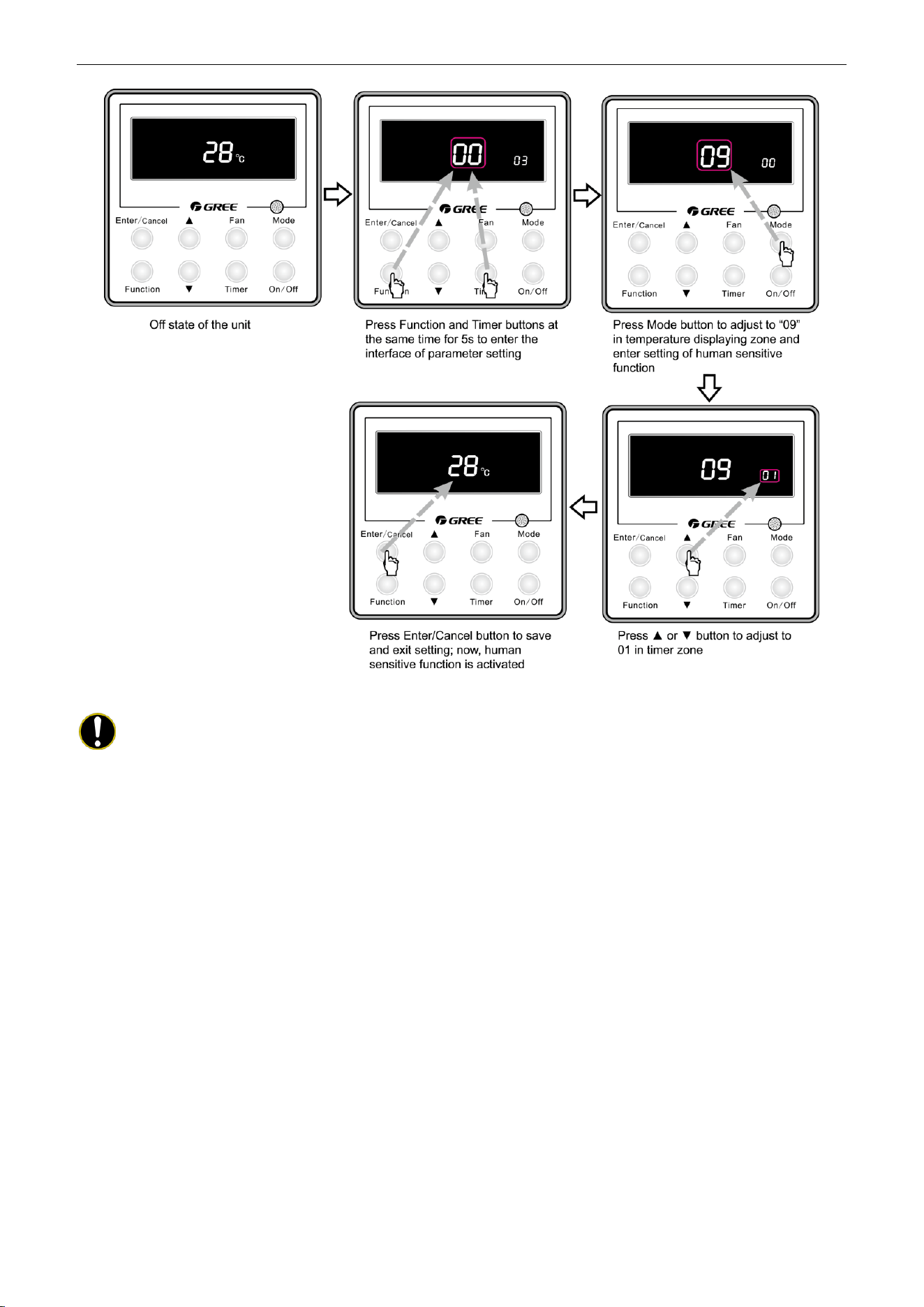
U-Match Series DC Inverter Service Manual
41
Figure 2-7-8
Note:
When door control function and human sensitive function have been set at the same time, it is
defaulted that door control function is valid and human sensitive function is invalid.
The user can purchase the human sensitive module by himself. Please pay attention to the following
notes:
① There is the needle stand interface on the main board. The interface model inserted into this
needle stand must be PH-3P-K;
② The current consumption of module can not exceed the current capacity provided by this
interface.
7.2.3 MODBUS interface
The indoor unit of this series has MODBUS interface. If the user needs to connect the unit to the
management system of the building, please enquire Gree for the MODBUS protocol.
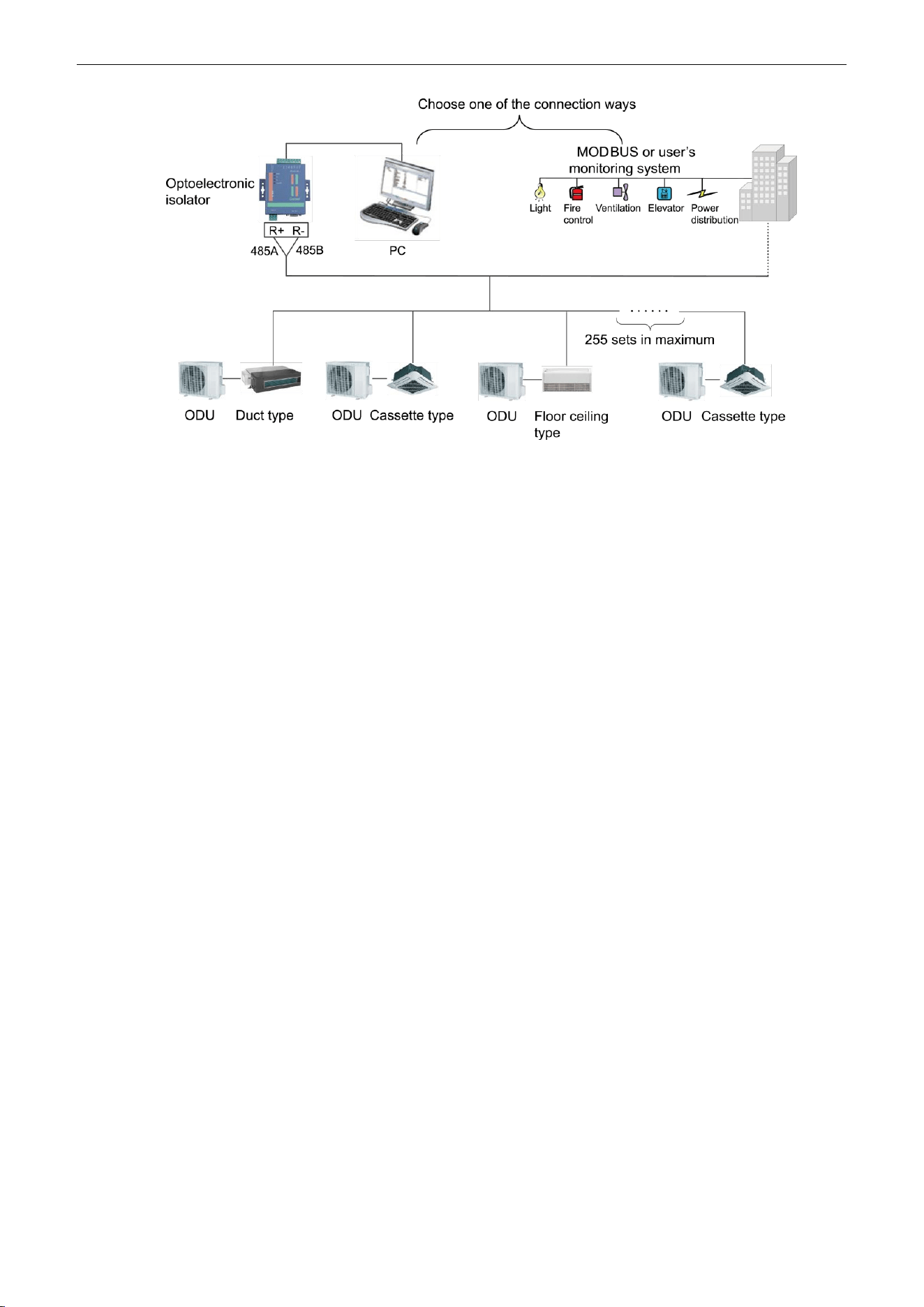
U-Match Series DC Inverter Service Manual
42
Figure 2-7-9
(1) Interface instruction:
1) The printing is COM-BMS1 and the interface type is B4B-XH-K3;
2) Electrical characteristic: baud rate: 9600bps; standard: RS485;
3) Working principle:
The indoor main board can send out the unit operation state through this interface and receive logical
control information to realize control and monitor of the unit.
(2) Function instructions:
In order to achieve this function, set the address mode and address through wired controller. Please
refer to Point 3 for the setting method. You must set the address mode into long-distance control address
mode.
The address mode is defaulted to be connecting to centralized controller mode and the defaulted
address is 1.
(3) Setting method:
1) Firstly, set the address mode of wired controller into centralized controller address mode. The
setting method is:
Under off state of the unit, press Function and Timer buttons at the same time for 5s to go to the
debugging menu. Press Mode button to adjust to “10” in temperature displaying zone. Timer zone displays
setting state and press ▲ or ▼ button to adjust. There are 2 selections:
① Centralized controller address mode (LCD displays 00)
② Long-distance control address mode (LCD displays 01)
Choose the second selection and then press Enter/Cancel button to save and exit setting. Now, the
address of wired controller is set to match the address of long-distance control. The unit will memorize this
setting status. The setting value will be memorized after power failure. The detailed setting is as shown in
the Figure below:
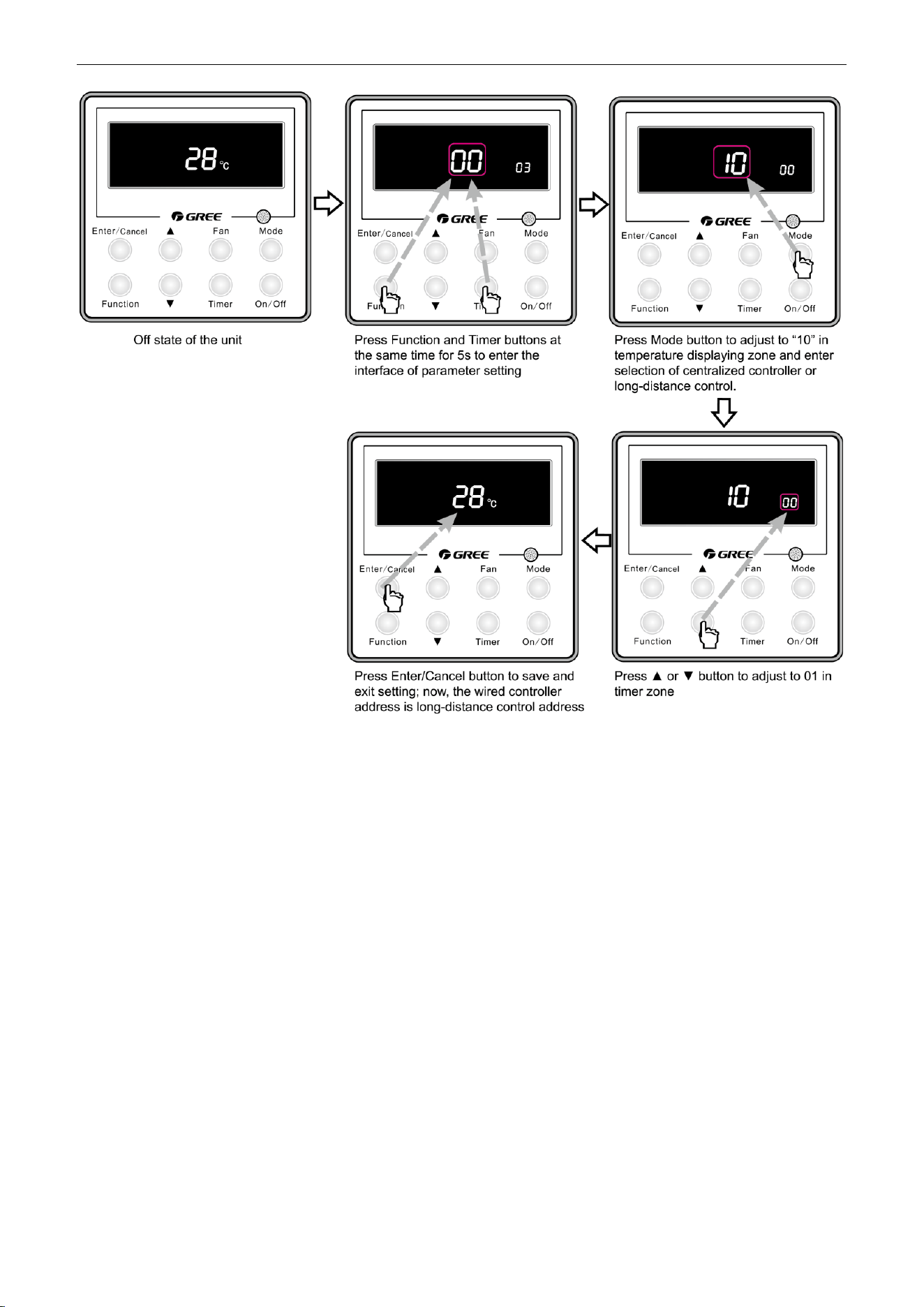
U-Match Series DC Inverter Service Manual
43
Figure 2-7-10
2) Address setting of each unit: when the address mode is set to be long-distance control address
mode. The address setting value range is 01~255. The setting method is:
Under off state of the unit, press Function and Mode buttons at the same time for 5s to enter setting
interface of wired controller address. LCD displays address sequence. Press ▲ or ▼ button to adjust the
address sequence and then press Enter/Cancel button to confirm. The setting value will be memorized
after power failure. The detailed setting is as shown in the Figure below:
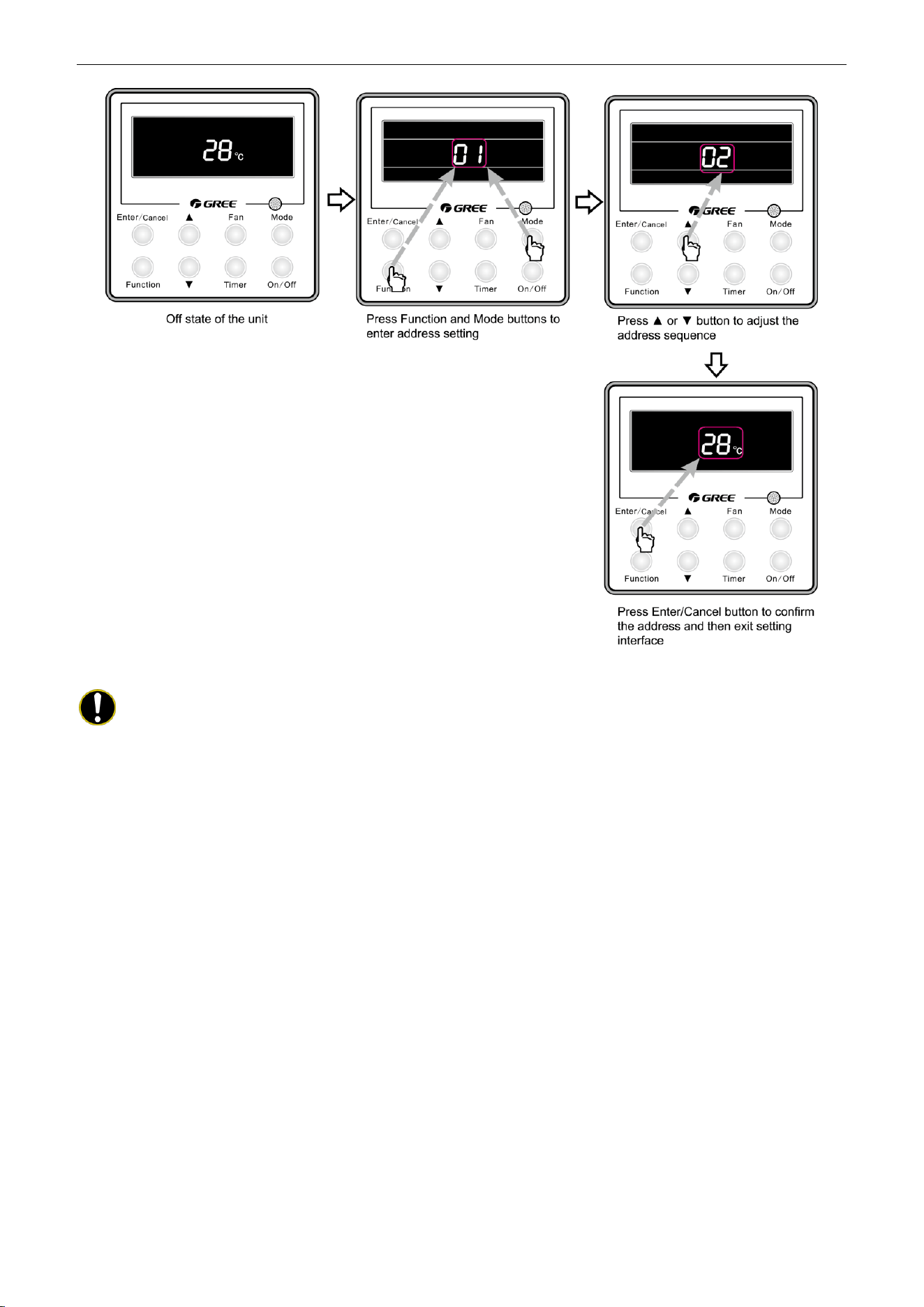
U-Match Series DC Inverter Service Manual
44
Figure 2-7-11
Notes:
① In order to realize the MODBUS interface function, the address mode of the unit must be set
into long-distance control address mode; you can not set it into centralized control address
mode, otherwise, this function can not be realized;
② The unit can not be connected to MODBUS and centralized controller at the same time; only
one of them can be selected;
③ 255 sets of unit in maximum can be connected in the same network; the unit addresses in the
same network must be different, otherwise, the unit control will be affected;
④ Perform wiring when the unit power is cut off.
7.2.4 Connect to interface of centralized controller:
The indoor unit is with the interface of centralized controller. When centralized controller is connected,
centralized control of unit can be realized when the wired controller is not connected;
(1) Interface instruction:
1) The printing is COM-BMS2, COM-BMS3 and the interface type is B2B-XH-K3;
2) Electrical characteristic: none;
3) Working principle: centralized control the communication of indoor main board and realize the
unit control;
(2) Function instructions:
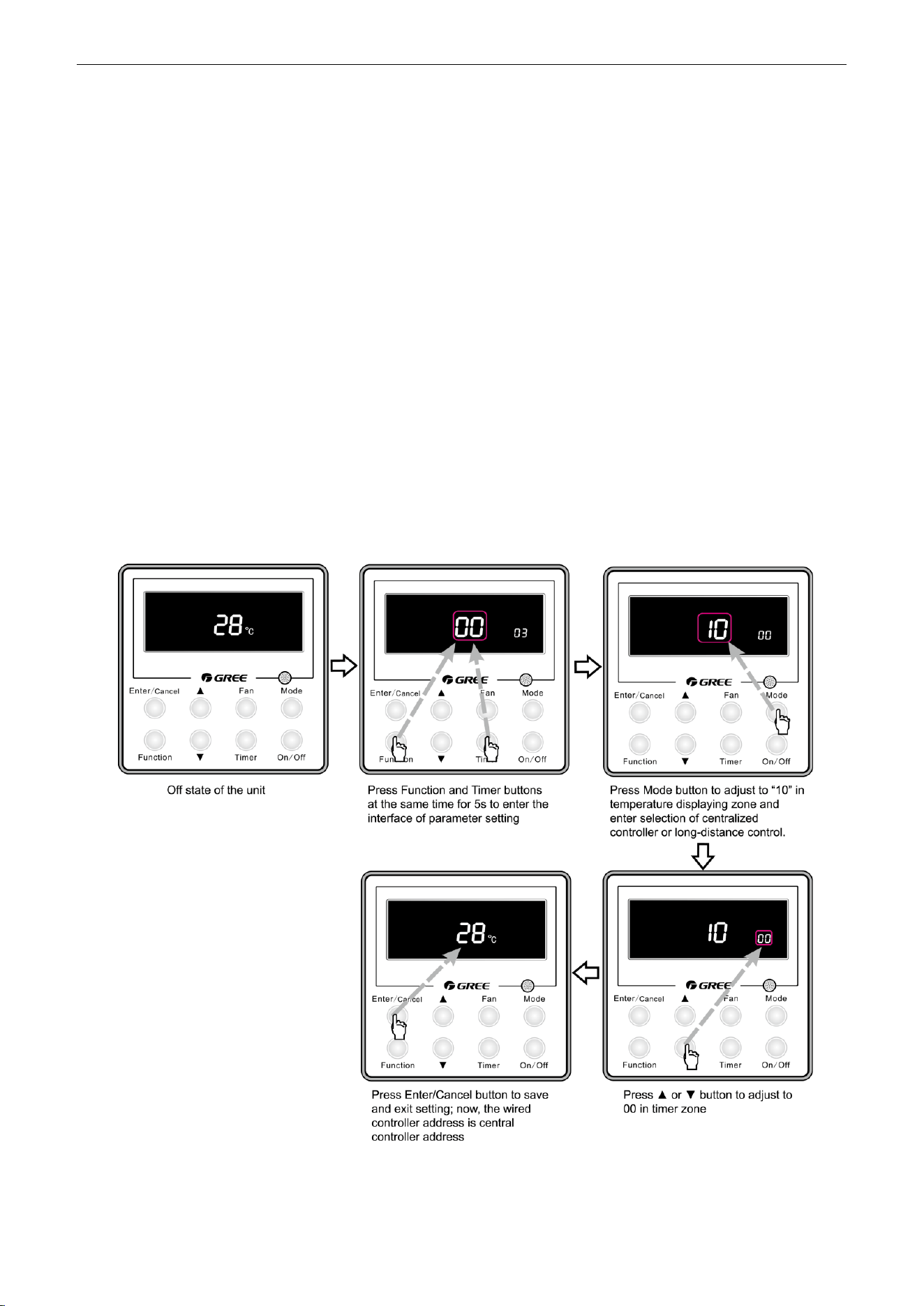
U-Match Series DC Inverter Service Manual
45
In order to achieve this function, set the address mode and address through wired controller. Please
refer to Point 3 for the setting method. The address mode is defaulted to be connecting to centralized
controller mode and the defaulted address is 1;
When the centralized controller is connected, centralized control of the unit can be realized to control
unit ON/OFF, operation mode, set fan speed/temperature and weekly timer.
(3) Setting method:
Firstly, set the address mode of wired controller into centralized controller address mode. The setting
method is:
1) Under off state of the unit, press Function and Timer buttons at the same time for 5s to go to
the debugging menu. Press Mode button to adjust to “10” in temperature displaying zone.
Timer zone displays setting state and press ▲ or ▼ button to adjust. There are 2 selections:
① Centralized controller address mode (LCD displays 00)
② Long-distance control address mode (LCD displays 01)
Choose the first selection and then press Enter/Cancel button to save and exit setting. Now, the
address of wired controller is set to match the address of centralized controller. The unit will memorize this
setting status. The setting value will be memorized after power failure. The detailed setting is as shown in
the Figure below:
Figure 2-7-12
2) Address setting of each unit: when the address mode is set to be centralized controller address
mode. The address setting value range is 01~16. The setting method is:
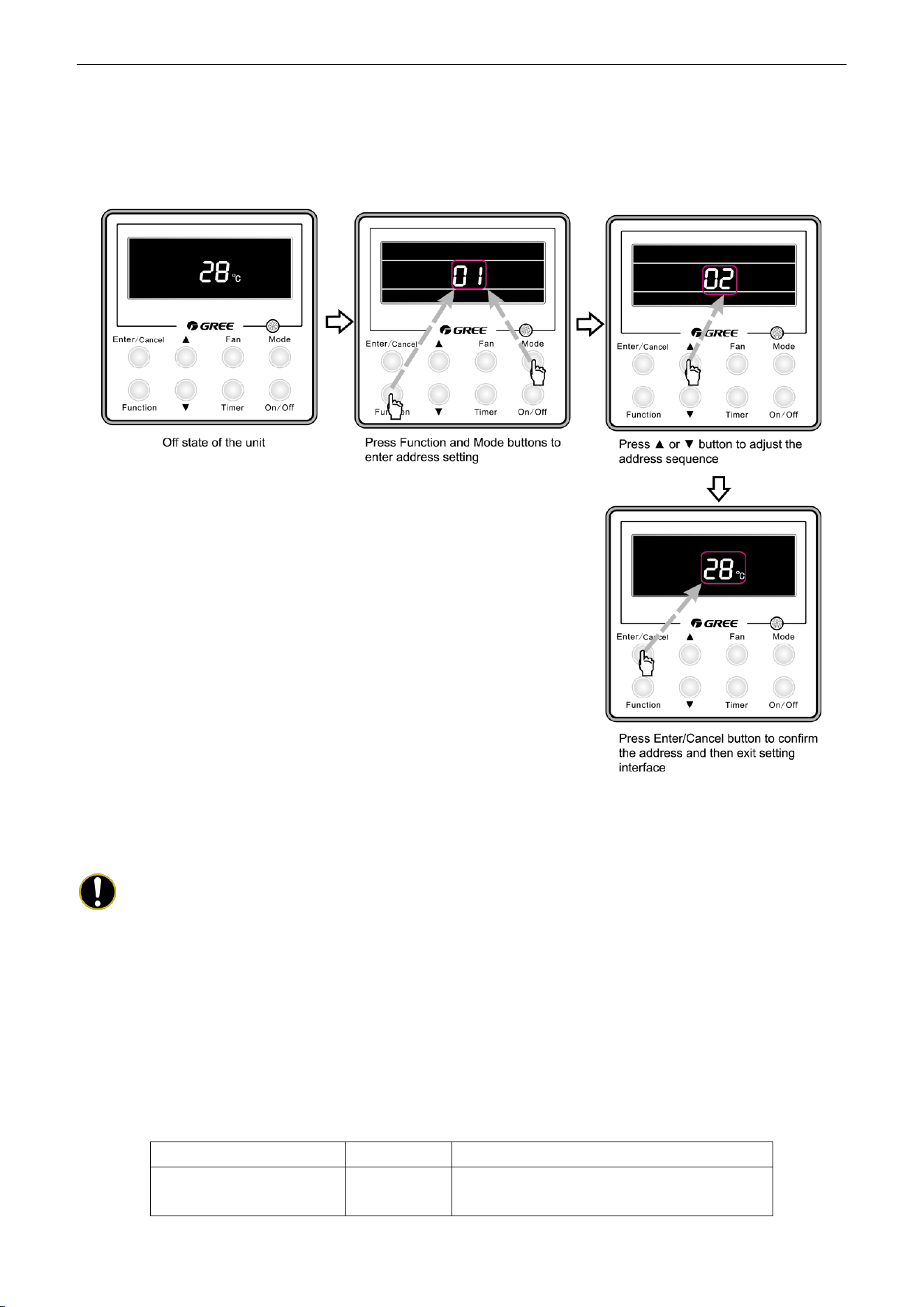
U-Match Series DC Inverter Service Manual
46
Under off state of the unit, press Function and Mode buttons at the same time for 5s to enter setting
interface of wired controller address. LCD displays address sequence. Press ▲ or ▼ button to adjust the
address sequence and then press Enter/Cancel button to confirm. The setting value will be memorized
after power failure. The detailed setting is as shown in the Figure below:
Figure 2-7-13
When the address is set, the wired controller can be removed and connect the centralized controller to
the indoor main board. Then connect the required units to realize centralized control of these units;
Notes:
① When centralized controller is to be connected, set the address mode into centralized
controller address mode through wired controller. Long-distance control address mode can
not be set;
② The unit addresses in the same network must be different, otherwise, communication
malfunction will occur and the unit can not work normally;
③ When centralized controller is to be connected, the unit address range is 1-16. Only 16 sets
of unit in maximum can be connected
④ The code and model of wired controller is as below:
Name
Product code
Remark
Centralized controller
CE50-24/E
MC207025
Only 16 sets of unit in maximum can be connected to
this controller
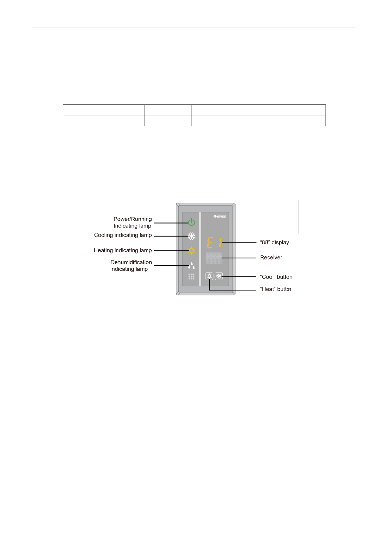
U-Match Series DC Inverter Service Manual
47
7.2.5 Light board control:
Light board interface is reserved on the main board of duct type unit. You can purchase Gree light
board to realize control of the unit. When wired control is also connected, you can realize control of the unit
through light board and wired controller.
Light board information:
Name
Product code
Remark
Receiving board Z6L
30260000001
Only for duct type unit
There are two buttons on the light board to control ON/OFF of cooling and heating. There are also
other indicators and nixie tube display.
Cooling: set temperature 26°(79℉), low fan speed; heating: set temperature 20°(68℉), low fan speed
Function instructions: under OFF state, pressing Cool/Heat button can turn on cooling/heating mode.
Under unit ON state, pressing Cool/Heat button can turn off the unit. When the unit is in cooling/heating
mode, pressing any button can turn off the unit.
Figure 2-7-14
7.2.6 Malfunction output of relay:
There is malfunction outlet signal on the main board of indoor unit; when the unit occurs unrecovered
malfunction, this signal will be output.
(1) Interface instruction:
1) Printing: X5, ERROR
2) Electrical characteristic OF malfunction indicator or electric bell: 220V~AC, power≤10W
3) Working principle: when the unit occurs unrecovered malfunction, the relay will suck and 220V
AC signal will be output.
(2) Function instructions:
When the user needs centralized control over several units, malfunction signals can be connected to
control room through this malfunction output interface. The user can indicate the unit malfunction through
malfunction indicator or electric bell, so the management people can go to check the malfunction unit
directly.
If dry contact detection of unit malfunction is needed, please connect this interface into the monitoring
system. When the closed signal is detected when malfunction occurs, this signal can be seen in monitoring
system.
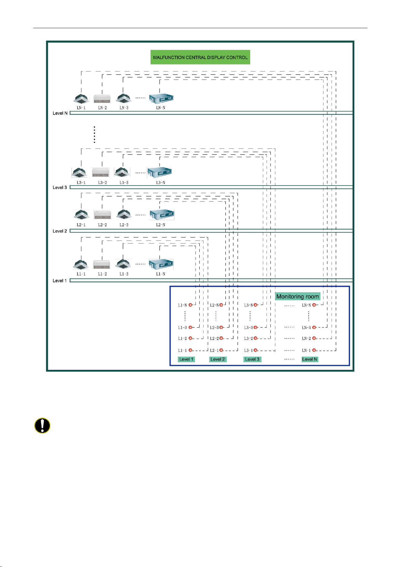
U-Match Series DC Inverter Service Manual
48
Figure 2-7-15 Malfunction output
(3) Setting method:
Do not need to set this function
Notes:
① The interface voltage should be 220V AC intense current;
② If malfunction light is connected, please make sure its power is not too big (it should be within
10W), otherwise, the relay on main board will be burnt.
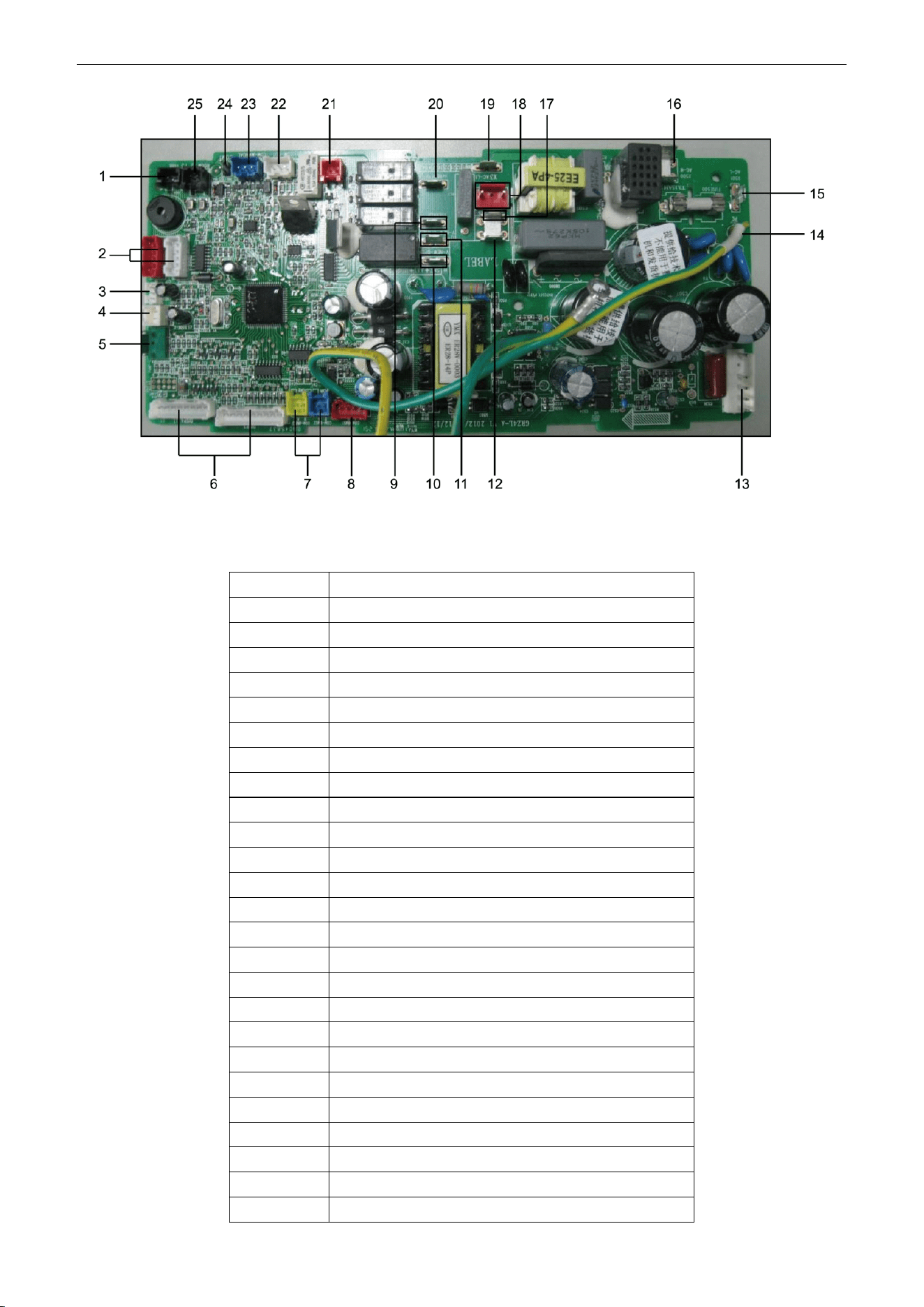
U-Match Series DC Inverter Service Manual
49
Figure 2-7-16
Table 2-7-4 Corresponding interfaces of main board
No.
Interface
1
Evaporator temperature sensor
2
Swing motor
3
Human sensitive
4
Door control
5
Full water detection
6
Interface of light board
7
Communication port of centralized controller
8
MODBUS interface
9
Interface of annunciator live wire
10
ON interface of fresh air valve
11
OFF interface of fresh air valve
12
Interface of annunciator neutral wire
13
Interface of DC motor
14
Main board grounding wire
15
Power live wire
16
Power neutral wire
17
Neutral wire of fresh air valve
18
Water pump interface
19
Live wire of fresh air valve
20
Interface of anion generator
21
Interface of auxiliary heating board
22
Interface of outdoor unit
23
Interface of wired controller
24
Monitor interface
25
Ambient temperature sensor
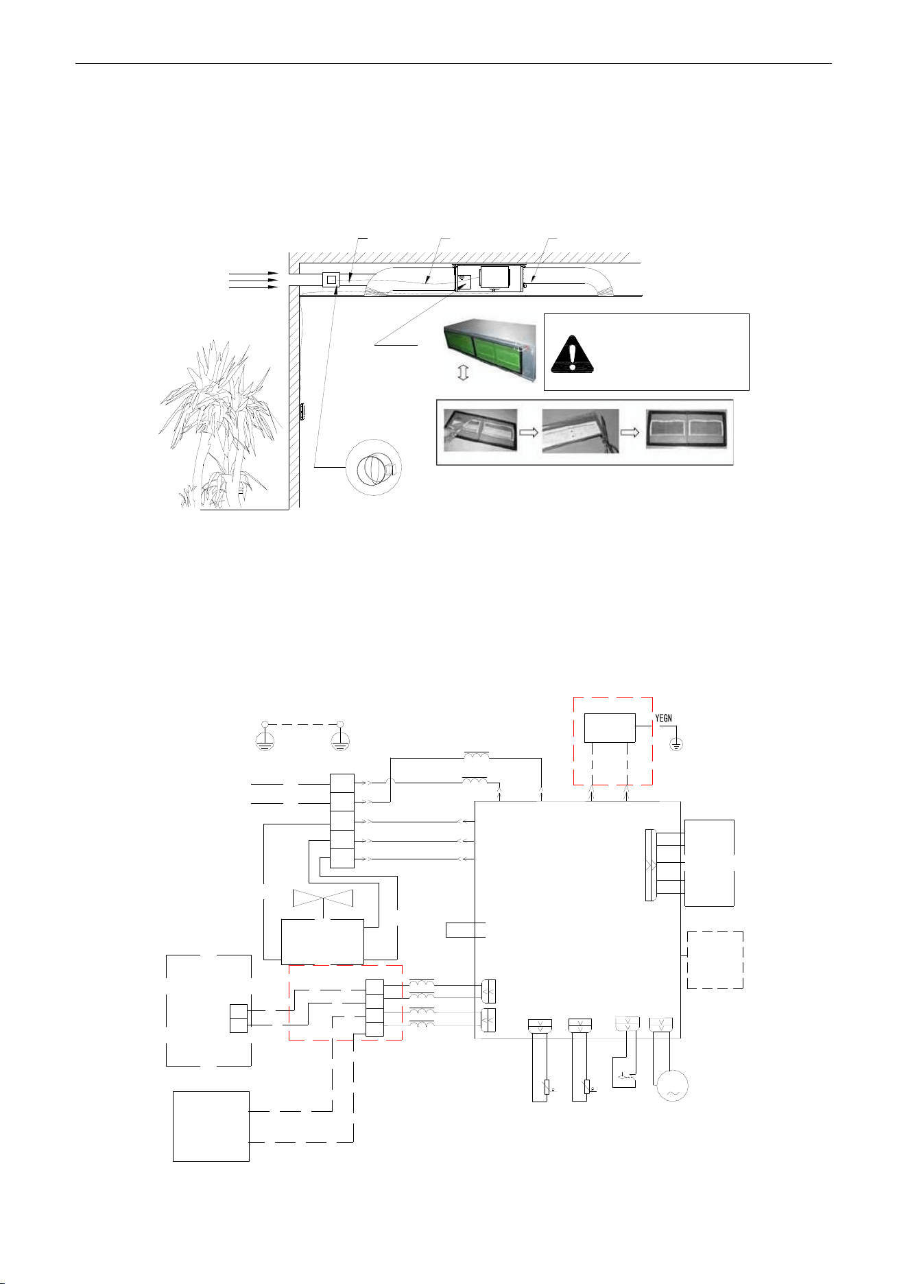
U-Match Series DC Inverter Service Manual
50
7.2.7 Reserved fresh air valve interface for duct type unit
For the reserved connection way of air valve performer, connect it to F, C, O of wiring board according
to the wiring diagram. Connect the public port of air valve to F, connect CLOSE to C and connect OPEN to
O.
Outdoor
fresh air
Fresh air
Air valve
Indoor
side
Air intake pipe
Air supply pipe
Before starting up the
unit, make sure remove
all the sealing film on
the healthy filter block.
Figure 2-7-17
7.2.8 Interface of anion generator
For the cold plasma anion generator, connect the red line to HEALTH(X4) and the blue line to N2(X6)
according to the principle circuit. The detector of cold plasma anion generator should be places at the air
return. The distance between two detectors should be 10mm (3/8inch) ≤ L ≤ 25mm (1inch).
MOTOR
WIRING
DIAGRAM
EARTH
WIRING
DIAGRAM
M
G
G
G
POWER
L1
L2
L1
L2
F
C
O
2BU
1RD
5WH
8BN
COOL PLASMA
GENERATOR
9RD
L1
L1
RD
BU
AP1
15WH
XT1
OUTDOOR
UNIT
1
2
WIRE
CONTROL
XT2
AP2
X1
X2
CLOSE
Fresh Air Valve
Common
OPEN
1
2
H1
H2
L2
L4
11RD
12BK
13BN
14OG
COM6
COM7
T2
T3
PUMP-C
PUMP
SA
15K
20K
LIQUID SWITCH
Environment
Temp. Sensor
Pipe
Temp. Sensor
Pump Motor
E500
N2(X6)
AC-L
(X501)
V-NEW-CLOSE(X2)
V-NEW-OPEN(X1)
AC-N
(X500)
HEALTH
(X4)
N2
(X6)
DC-MOTOR1
Figure 2-7-18
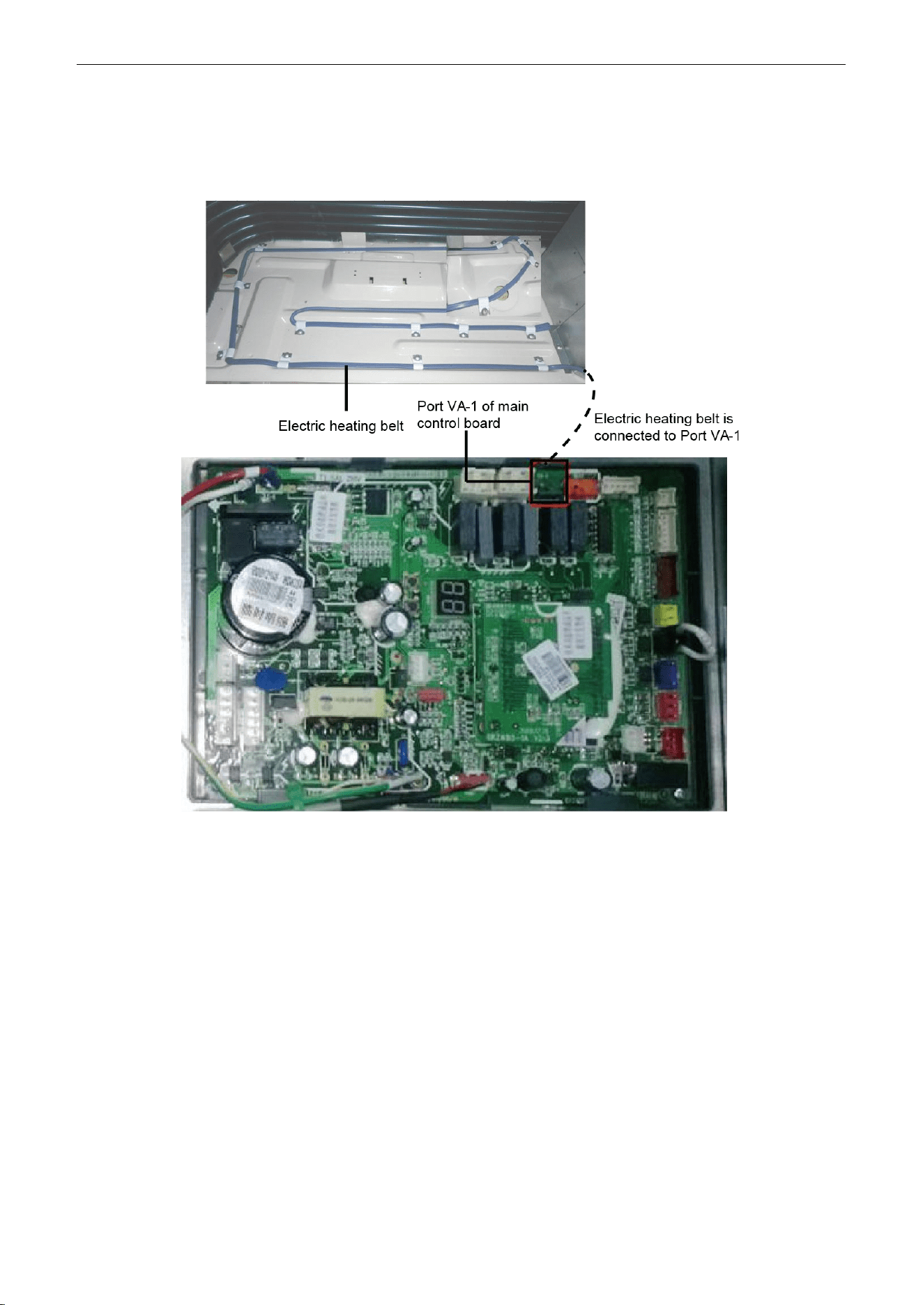
U-Match Series DC Inverter Service Manual
51
7.2.9 Chassis electric heating belt of outdoor unit is optional
When outdoor ambient temperature is very low, electric heating belt can be equipped on the chassis to
prevent freezing of the chassis.
Figure 2-7-19

U-Match Series DC Inverter Service Manual
52
INSTALLATION

U-Match Series DC Inverter Service Manual
53
INSTALLATION
1 INDOOR UNIT INSTALLATION
1.1 Installation of Duct Type
1.1.1 Before Installation
After receiving the machine, please check for any transport damage. If finding any surface or internal
damage, please immediately report to the transport company or equipment company in writing.
After receiving the machine, please check the unit and accessories in reference to the packing list.
Ensure that the model is correct and the machine is in good condition. Please also check if the specification
and quantity of accessory parts are correct.
Determine the correct handling route and methods, thus to avoid damaging the unit or causing
possible hazard. For the sake of protection and safety, it is suggested to move the unit with the packaging
box. Even though it is not permitted to do like this under special occasions, do not remove the packaging
box, thus to avoid loosening or falling during handling.
Confirm if the installing foundation is solid. When this unit is to be installed on the metal section of the
building, make sure that the electrical insulation must comply with applicable standards.
Ensure that the place of installation is far from the area where the inflammable or explosive
substances are stored, thus to avoid possible explosion or fire due to leakage.
1.1.2 Installation Site
Ensure the top hanging piece has strong strength to withstand the weight of the unit.
The drainage pipe has convenient flow of water.
There is no obstacle blocking the return air inlet and exhaust outlet, so as to ensure sound air
circulation.
The installation spaces required by the drawing must be ensured, so as to provide enough space for
the service and maintenance.
The installation site must be far away from heat source, leakage of inflammable gas or smoke.
The indoor unit is of ceiling mount (indoor unit is hidden inside the ceiling).
The indoor and outdoor units, the power cable and the connecting electrical lines must be at least 1
meter from any TV set or radio. This is to avoid image interference or noise of the TV set or radio. (Even if
the distance is 1 meter, noise can also exist if there is strong electric wave.)
1.1.3 Caution for Installation
Generally, the unit is installed indoor on ceiling. For ceiling mounting, ensure that the hangers on
ceiling have adequate strength to support the weight of the unit.
To meet the noise and vibration requirements, the unit shall be installed by using rubber pad (thickness
≥20mm (13/16inch)) and rubber connector.
Insert a M10 expansion bolt into the hole. Drive a nail into the bolt. Refer to the profile dimensions
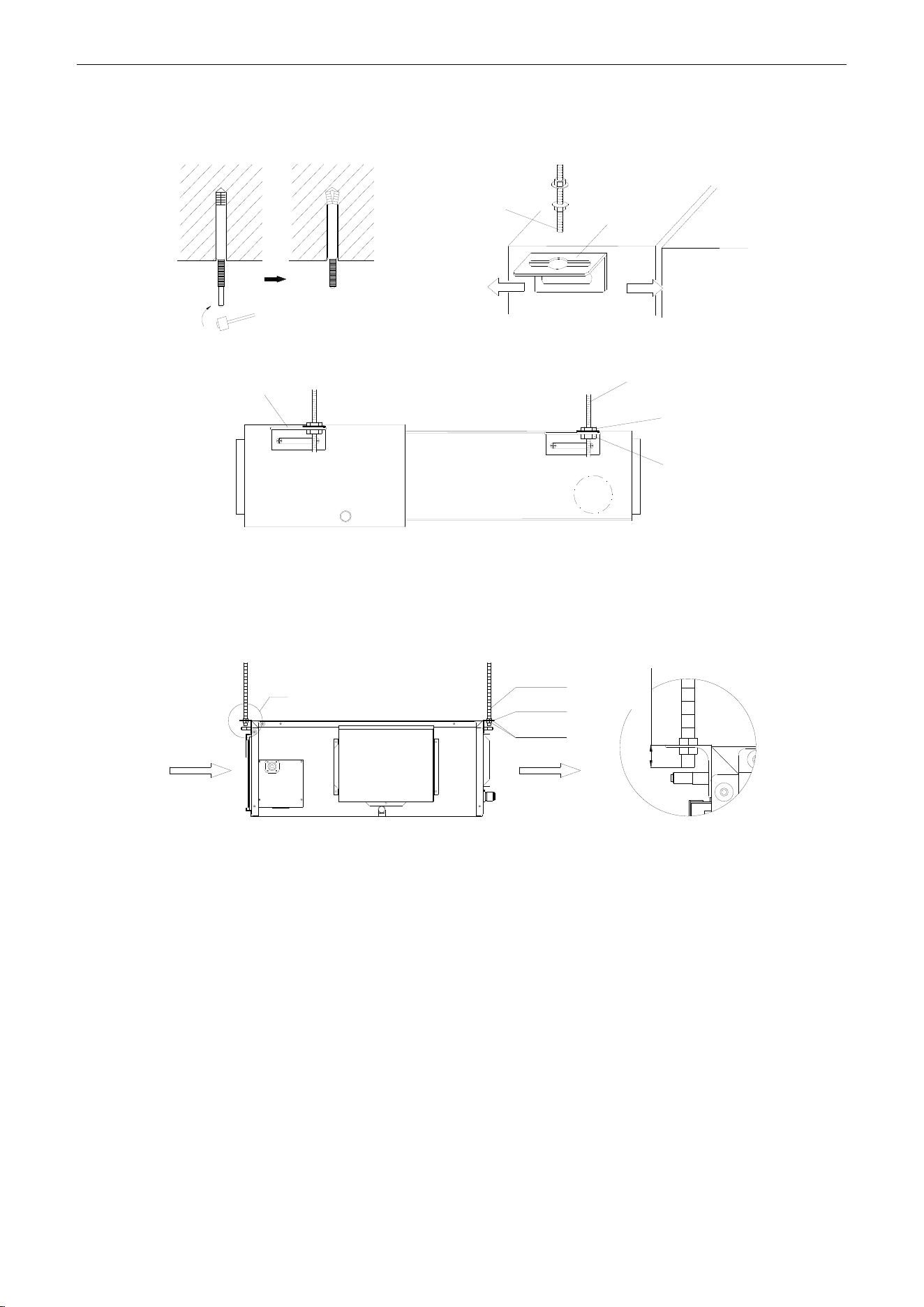
U-Match Series DC Inverter Service Manual
54
drawing of the indoor unit for the distance between the holes. Refer to Figure 3-1-1 for the installation of the
expansion bolt.
Ceiling-mount
Screw
Air-conditioning Unit
Hanger
Figure 3-1-1 Figure 3-1-2
Hook
Screw
Nut
Nut
Figure 3-1-3
Install the hanger onto the indoor unit as Figure 3-1-2 and Figure 3-1-3 shows.
Install the indoor unit at the ceiling as Figure 3-1-4 shows.
I
Air Intake
Air Supply
Screw
Hanger
Nut
≤48mm(1-7/8inch)
I Detail
Figure 3-1-4
Precautions for unfavorable installation:
The preparation of all pipes (connecting pipes and drainage pipes) and cables (connecting lines of
wire controller, indoor unit and outdoor unit) must be ready before the installation, so as to achieve smooth
installation.
Drill an opening on the ceiling. Maybe it is required to support the ceiling to ensure the evenness of it
and avoid the vibration of it. Consult with the user or a construction company for details.
In case the strength of ceiling is not enough, use angle iron sections to set up a beam support. Place
the unit at the beam and fix it.
Level inspection of the indoor unit
After the indoor unit is installed, it is required to check the level of the whole unit. The unit must be
placed horizontally, but the condensate pipe shall be installed obliquely, so as to facilitate the drainage of
condensate.
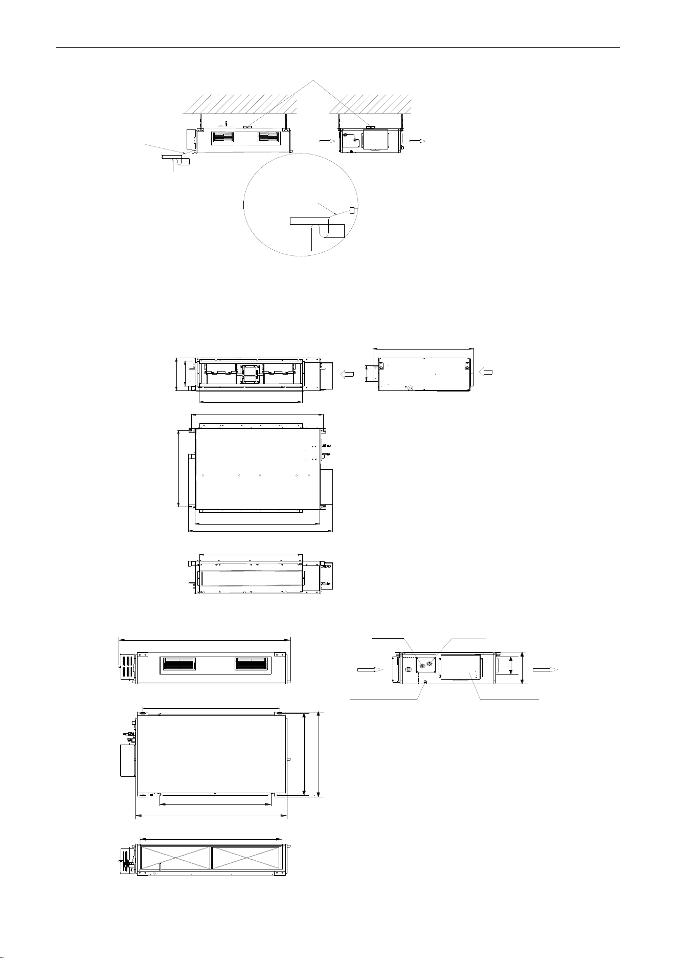
U-Match Series DC Inverter Service Manual
55
Condensate
Drainpipes
Level Instrument
Air Intake
Air Supply
B
A
B
Enlarged View
Condensate Drainpipe
As the inside of the unit is in the negative
pressure status, it is required to set up a
backwater elbow. The requirements is:
A=B≥(0.145P/10000+20)/25.4(inch)
P is the absolute pressure inside the unit.
The unit of the pressure is psig.
Figure 3-1-5
1.1.4 Dimension Data
For the units: 18k
Air intake
A
Max
Max
B
C
D
E
F
G
H
I
J
For the units: 24k~42k
E
Max
A
C
D
B
F
Max
G
I
H
J
Gas Pipe Liquid Pipe
Air Intake
Drainage Pipe
Electric Box
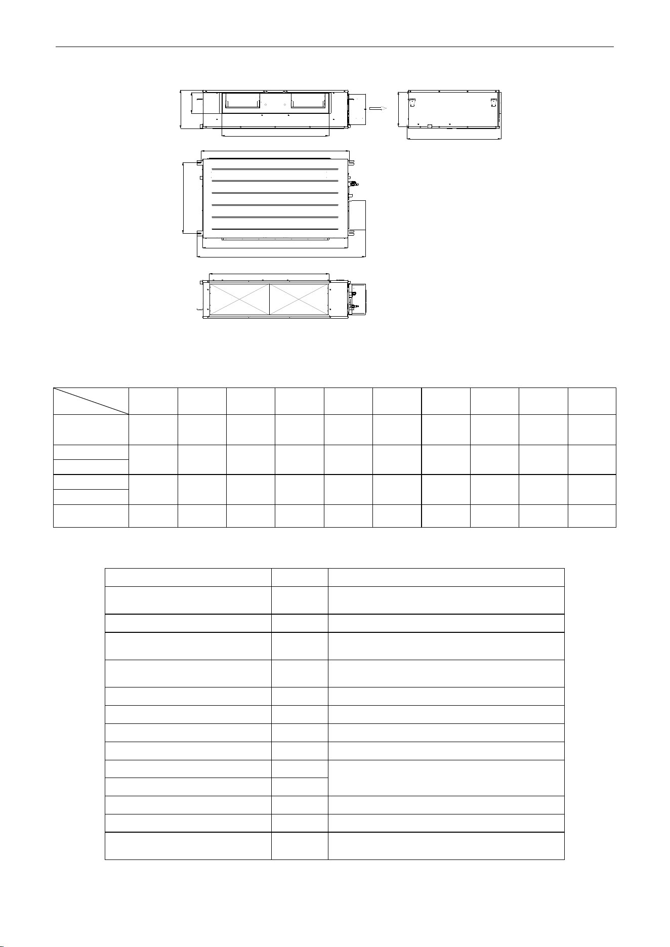
U-Match Series DC Inverter Service Manual
56
For the units: 48k
A
B
C
D
E
F
G
H
I
J
Figure 3-1-6
Table 3-1-1
Unit: mm (inch)
Item
Model
A
B
C
D
E
F
G
H
I
J
UMAT18HP230V1AD
945
(37-1/4)
620
(24-3/8)
740
(29)
890
(35-1/8)
1035
(40-7/8)
720
(28-3/8)
740
(29)
125
(4-7/8)
205
(8)
265
(10-1/2)
UMAT24HP230V1AD
1100
(43-3/8)
515
(20-3/8)
820
(32-1/4)
1160
(45-5/8)
1280
(50-3/8)
560
(22)
1000
(39-1/2)
160
(6-1/4)
235
(9-1/4)
270
(10-1/2)
UMAT30HP230V1AD
UMAT36HP230V1AD
1010
(39-3/4)
750
(29-1/2)
820
(32-1/4)
1115
(43-7/8)
1225
(48-1/4)
775
(30-1/2)
980
(38-1/2)
160
(6-1/4)
230
(9-1/8)
290
(11-3/8)
UMAT42HP230V1AD
UMAT48HP230V1AD
1170
(46-3/8)
645
(25-3/8)
850
(33-1/2)
1150
(45-1/4)
1340
(52-3/4)
750
(29-1/2)
950
(37-1/2)
190
(7-1/2)
315
(12-1/2)
350
(13-3/4)
Table 3-1-2 Installation Accessories List for Duct-type Indoor Unit
Name & Shape
QTY
Notes
Installation and Operating
Instructions
1
Insulation materials for gas pipe
1
Used for gas pipe connector on indoor unit.
Insulation materials for liquid
pipe
1
Used for liquid pipe connector on indoor unit.
Insulation materials for drainage
pipe
2
Used for wrapping the condensate pipe and
rubber plug.
Nut
1
To connect liquid pipe.
Nut
1
To connect gas pipe.
Nut M6 with gasket
8
Use for fixing the hanger hook.
Nut M10 with gasket
4
Use for fixing the hanger hook.
Nut M10
4
4 sets, used for ceiling mounting of the indoor
unit.
spring gasket
4
Hook
4
Used for ceiling mounting of the indoor unit.
Wired controller
1
Screw M4
2
To fix the base plate of wired controller and
installation hole of the wall together.
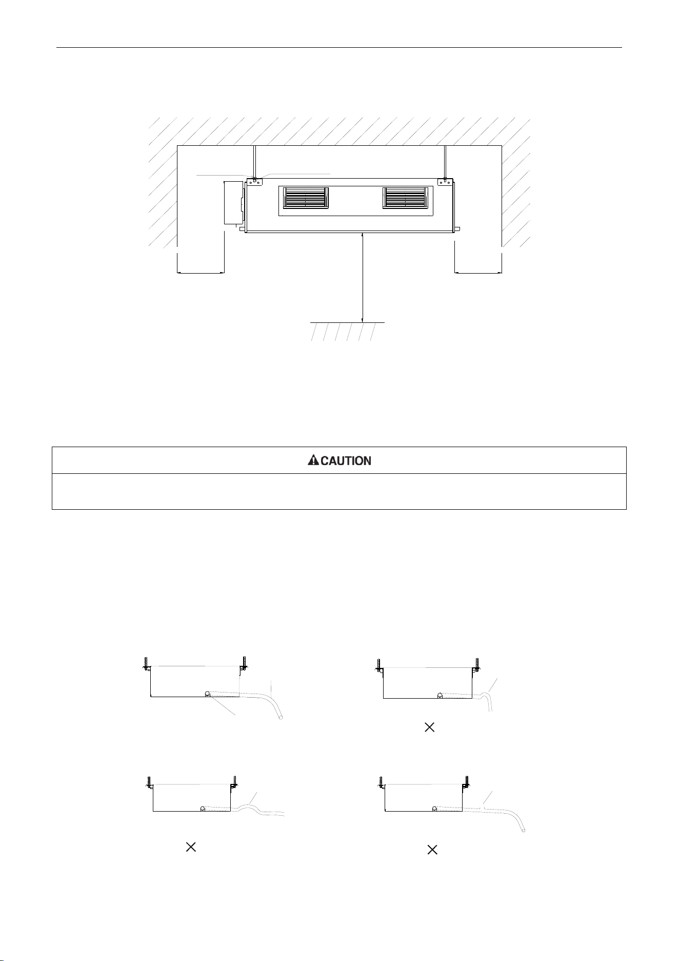
U-Match Series DC Inverter Service Manual
57
1.1.5 Installation Clearance Data
>2500mm
(98-3/8inch)
Nut with
Washer
Nut Spring
Washer
>250mm
(9-7/8inch)
>250mm
(9-7/8inch)
Figure 3-1-7
Warning! The height of installation for the indoor unit should be 2.5m (8-1/5ft) above.
1.1.6 Drain Piping Work
Installation of Drainage Pipeline:
Install the drain hose in accordance with the instructions in this installation manual and keep the area warm enough to
prevent condensation. Problems with the piping may lead to water leaks.
(1) (Install the drain hose with downward gradient (1/50 to 1/100) and no risers or traps are used for
the hose (Figure 3-1-8).
(2) Be sure there is no crack or leak on the drain hose to avoid the formation of air pocket (Figure
3-1-8).
(3) When the hose is long, install supporters (Figure 3-1-9).
(4) Always use the drain hose which has been insulated properly.
Drain hose
Arrange the drain hose
lower than this drain port
Trap
Air bleeding
Rise
√
Figure 3-1-8
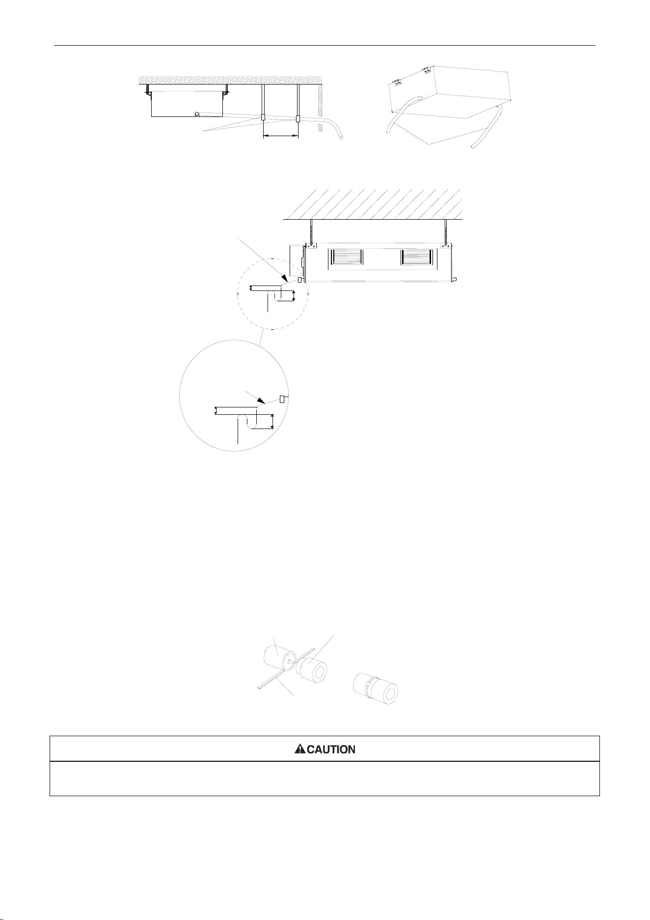
U-Match Series DC Inverter Service Manual
58
Supporter
Drain hose
1~1.5m(3-2/7~5feet)
Figure 3-1-9 Figure 3-1-10
Condensate Drainpipe
B
A
As the inside of the unit is in the
negative pressure status, it is required
to set up a backwater elbow. The
requirements is:
A=B≥(0.145P/10000+20)/25.4(inch)
P is the absolute pressure inside the
unit. The unit of the pressure is psig.
Condensate Drainpipe
Enlarged View
B
A
Figure 3-1-11
(5) Use a suitable drain hose, and see Table 3-3-3 for its size.
(6) There is a drain port on both the left and right sides. Select the drain port to match the local
conditions (Figure 3-1-10).
(7) When the unit is shipped from the factory, the drain port is defaulted to be the one on the left side
(electric box side), the port on right side has been plugged.
(8) When using the drain port on the right side of the unit, reinstall the drain cap to the left side drain
port (Figure 3-1-12).
Drain port
Fastener
Drain cap
Figure 3-1-12
Always check that the drain cap is installed to the unused drain port and is fastened with the nylon fastener. If the drain
cap is not installed, or is not sufficiently fastened by the nylon fastener, water may drip during the cooling operation.
(9) Be sure to insulate where the drain port and the drain hose is connected (Figure 3-1-13).
(10) The unused drain port also should be insulated properly (Figure 3-1-14).
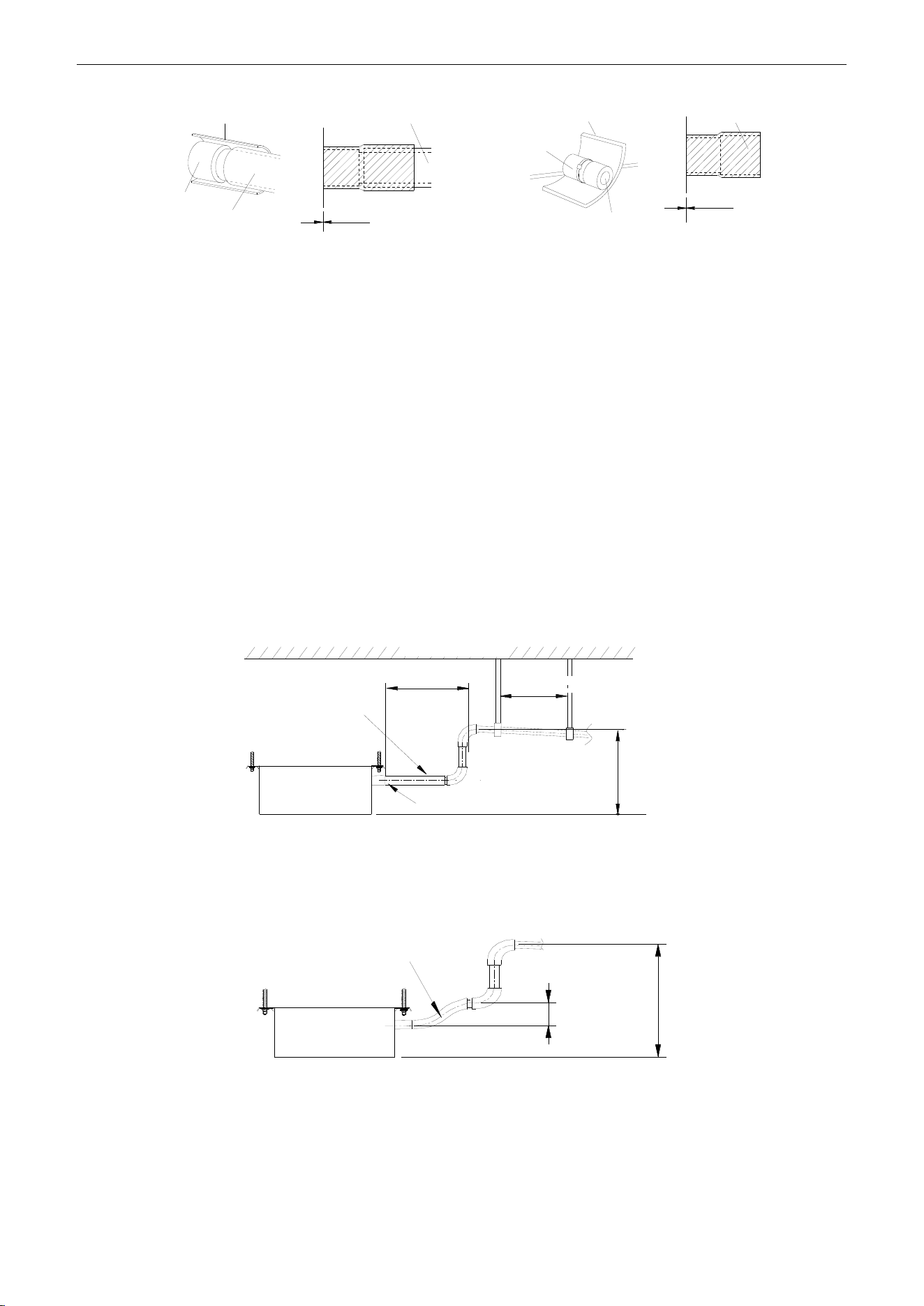
U-Match Series DC Inverter Service Manual
59
Drain hose insulation
Drain port
Insulated drain hose
Insulated drain hose
Unit
0mm(0inch)
Drain hose insulation
Drain port
Drain cap
0mm(0inch)
Unit
Drain cap
Figure 3-1-13 Figure 3-1-14
(11) There is adhesive on one side of the insulation so that after removing the protective paper over it
the insulation can be directly attached to the drain hose.
(12) Considerations for the unit with the condensate pump:
1) For the unit with the condensate pump, only one drain port at the side close to the electric box
is prepared and only through it the drain hose can be connected.
2) See table 3 for the size of the drain port of the unit with the condensate pump, which is different
from that of the unit without the condensate pump.
3) For the unit with the condensate pump, two drain ports at the bottom are defaulted to be factory
plugged with drain caps. After the installation of the drain hose, these two drain ports also need
to be insulated properly with the same way aforementioned.
4) The drain hose for the unit with the condensate pump should be arranged as shown in the
figure below.
Ceiling
Hoisting stand
Clamp(attachment)
Drain hose(attachment)
Drain raising
hose
≤300mm(11-3/4inch)
1000~1500mm(39-3/8~59inch)
≤100mm
(39-3/8inch)
Figure 3-1-15
① The vertical height of the drain hose should be 75mm (3inch) or less so that it is unnecessary
for the drain port to withstand additional force.
Drain hose(attachment)
≤75mm(3inch)
≤1000mm
(39-3/8inch)
Figure 3-1-16
② When multiple drain hoses are used, their installation should be performed as shown in the
figure below.
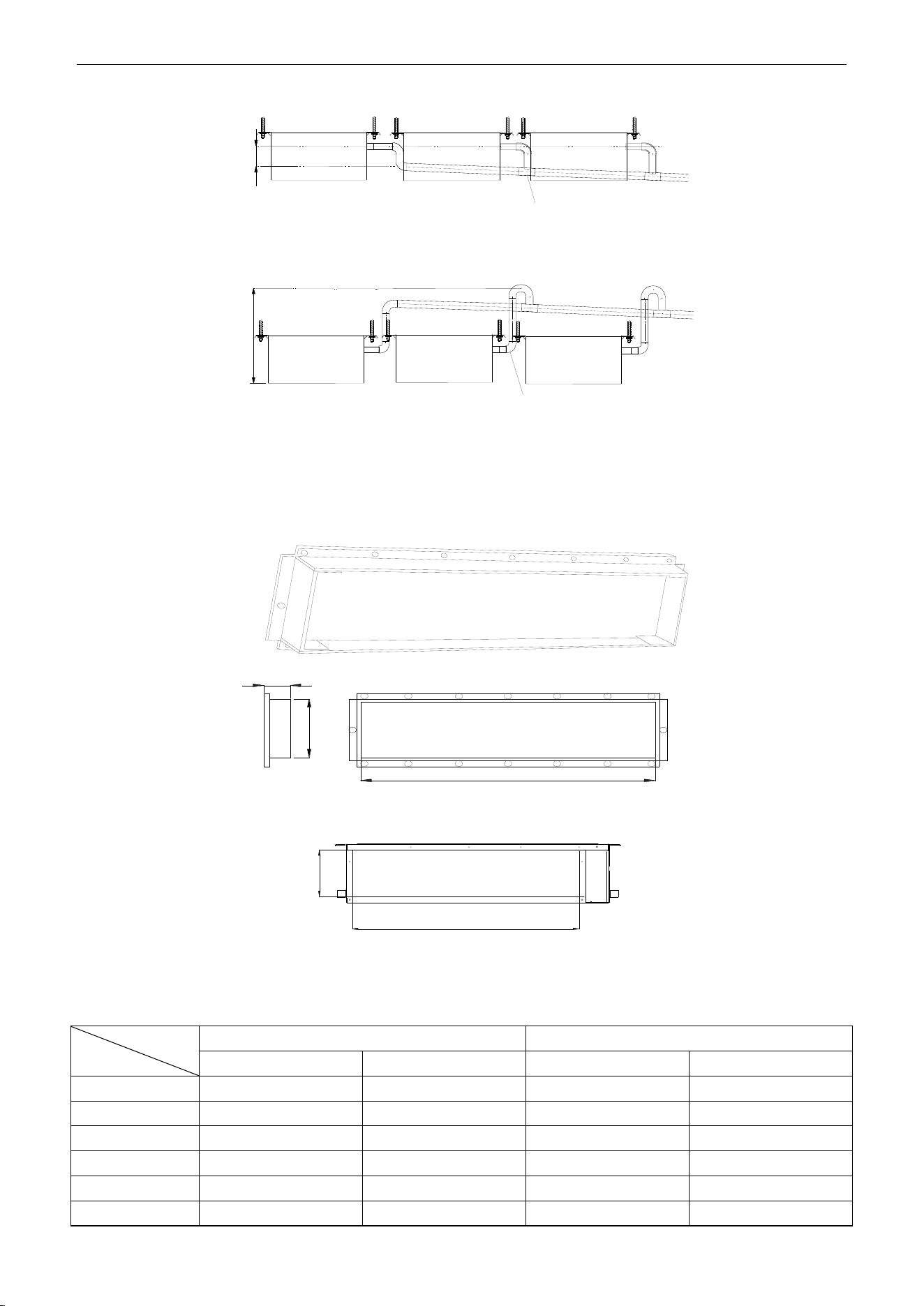
U-Match Series DC Inverter Service Manual
60
0~1000mm(0~39-3/8inch) ≥100mm(3-7/8inch)
T-joint converging drain pipes
T-joint converging drain pipes
Figure 3-1-17
1.1.7 Installation of air duct
Dimensions of the Supply Air Outlet/Return Air Inlet
B
A
21mm(7/8inch)
Figure 3-1-18 Supply Air Outlet
C
D
Figure 3-1-19 Return Air Inlet
Table 3-1-3
Unit: mm (inch)
Item
Model
Supply Air Outlet
Return Air Inlet
A
B
C
D
UMAT18HP230V1AD
123(4-7/8)
736(29)
710(28)
166(6-1/2)
UMAT24HP230V1AD
158(6-1/4)
818(32-1/4)
994(39-1/8)
195(7-5/8)
UMAT30HP230V1AD
158(6-1/4)
818(32-1/4)
994(39-1/8)
195(7-5/8)
UMAT36HP230V1AD
158(6-1/4)
818(32-1/4)
1000(39-3/8)
206(8-1/8)
UMAT42HP230V1AD
158(6-1/4)
818(32-1/4)
1000(39-3/8)
206(8-1/8)
UMAT48HP230V1AD
190(7-1/2)
850(33-1/2)
940(37)
286(11-1/4)
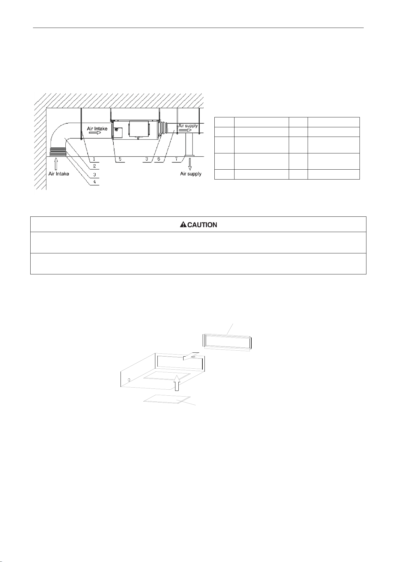
U-Match Series DC Inverter Service Manual
61
1.1.8 Installation of the Supply Air Duct
(1) Installation of the Rectangular Duct.
Figure 3-1-20
①. The maximum length of the duct means the maximum length of the supply air duct plus the maximum length of the
return air duct.
②. The duct is rectangular and connected with the air inlet/outlet of the indoor unit. Among all supply air outlets, at
least one should be kept open.
Bottom Return Air Installation only for Units 18k
(2) The default installation location of the rectangular flange is at the back and the return air cover
plate is at the bottom, as shown in Figure 3-1-21.
Rear Return Air
Rectangular Flange
Bottom Return Air
Return Air Cover Plate
Figure 3-1-21
(3) If the bottom return air is desired, just change the place of the rectangular flange and the return air
cover plate.
(4) Connect one end of the return air duct to the return air outlet of the unit by rivets and the other to
the return air louver. For the sake of the convenience to freely adjust the height, a cutting of
canvas duct will be helpful, which can be reinforced and folded by 8# iron wire.
(5) More noise is likely to be produced in the bottom return air mode than the backward return air
mode, so it is suggested to install a silencer and a static pressure box to minimize the noise.
(6) The installation method can be chosen with considering the conditions of the building and
Table 3-1-4 Installation of the rectangular duct
No.
Name
No.
Name
1
Hanger
5
Filter
2
Air Intake Pipe
6
Main Air
Supply Pipe
3
Canvas Air Pipe
7
Air Supply
Outlet
4
Air Intake
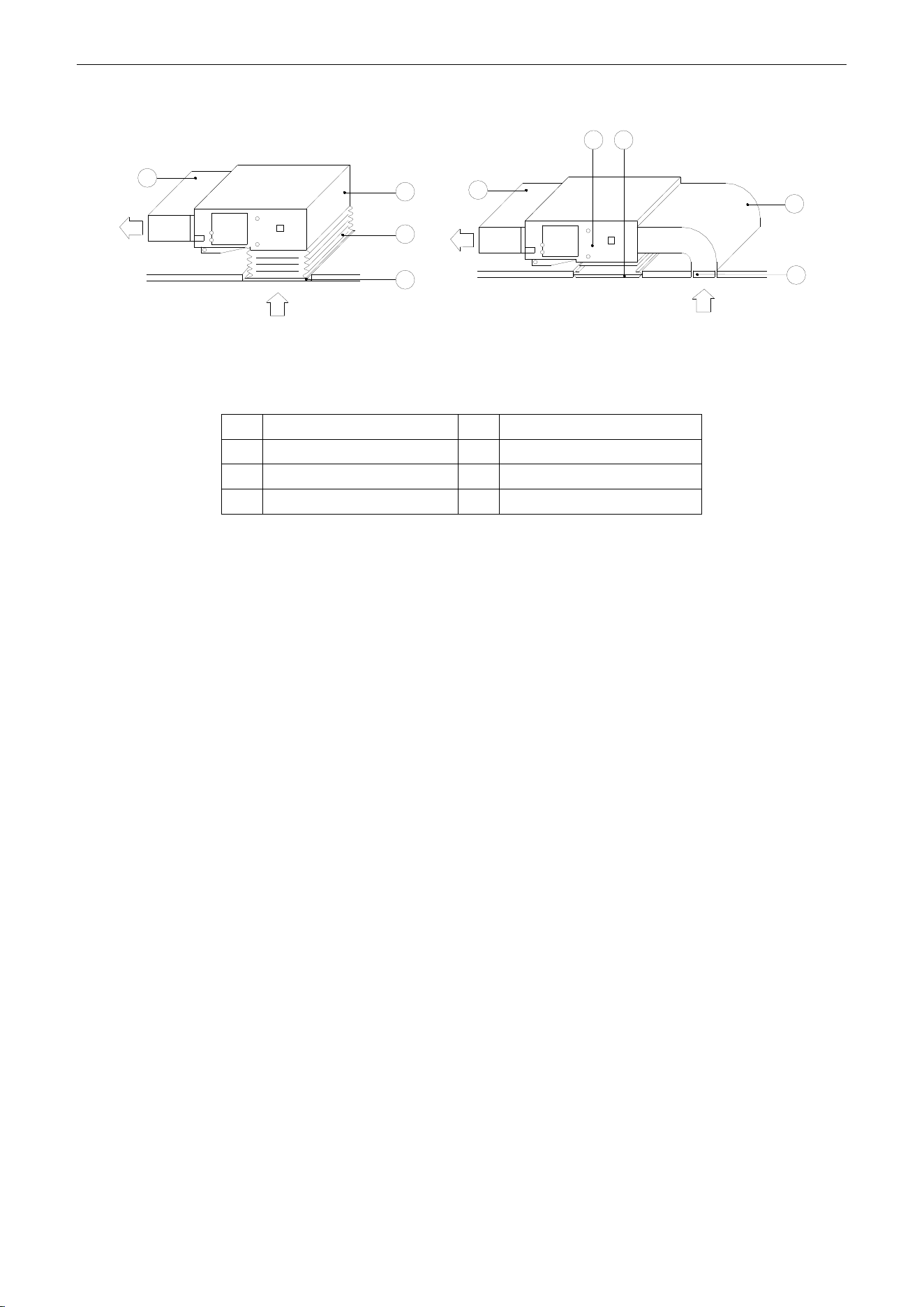
U-Match Series DC Inverter Service Manual
62
maintenance etc., as shown in Figure 3-1-22.
Supply air
Return air
1
Supply air
Return air
Install the return air duct(a) Install the return air duct(b)
2
4
5
5
4
6
3
1
Figure 3-1-22
Table 3-1-5 Installation of the return air duct
No.
Name
No.
Name
1
Return Air Inlet (with filter)
4
Indoor unit
2
Canvas Duct
5
Supply Air Duct
3
Return Air Duct
6
Grille
1.2 Installation of Floor Ceiling Type
1.2.1 Before Installation
After receiving the machine, please check for any transport damage. If finding any surface or internal
damage, please immediately report to the transport company or equipment company in writing.
After receiving the machine, please check the unit and accessories in reference to the packing list.
Ensure that the model is correct and the machine is in good condition. Please also check if the specification
and quantity of accessory parts are correct.
Determine the correct handling route and methods, thus to avoid damaging the unit or causing
possible hazard. For the sake of protection and safety, it is suggested to move the unit with the packaging
box. Even though it is not permitted to do like this under special occasions, do not remove the packaging
box, thus to avoid loosening or falling during handling.
Confirm if the installing foundation is solid. When this unit is to be installed on the metal section of the
building, make sure that the electrical insulation must comply with applicable standards.
Ensure that the place of installation is far from the area where the inflammable or explosive
substances are stored, thus to avoid possible explosion or fire due to leakage.
1.2.2 Installation Site
(1) Install the unit at a place where is strong enough to withstand the weight of the unit.
(2) The air inlet and outlet of the unit should never be clogged so that the airflow can reach every
corner of the room.
(3) Leave service space around the unit as required in Figure 3-1-23.
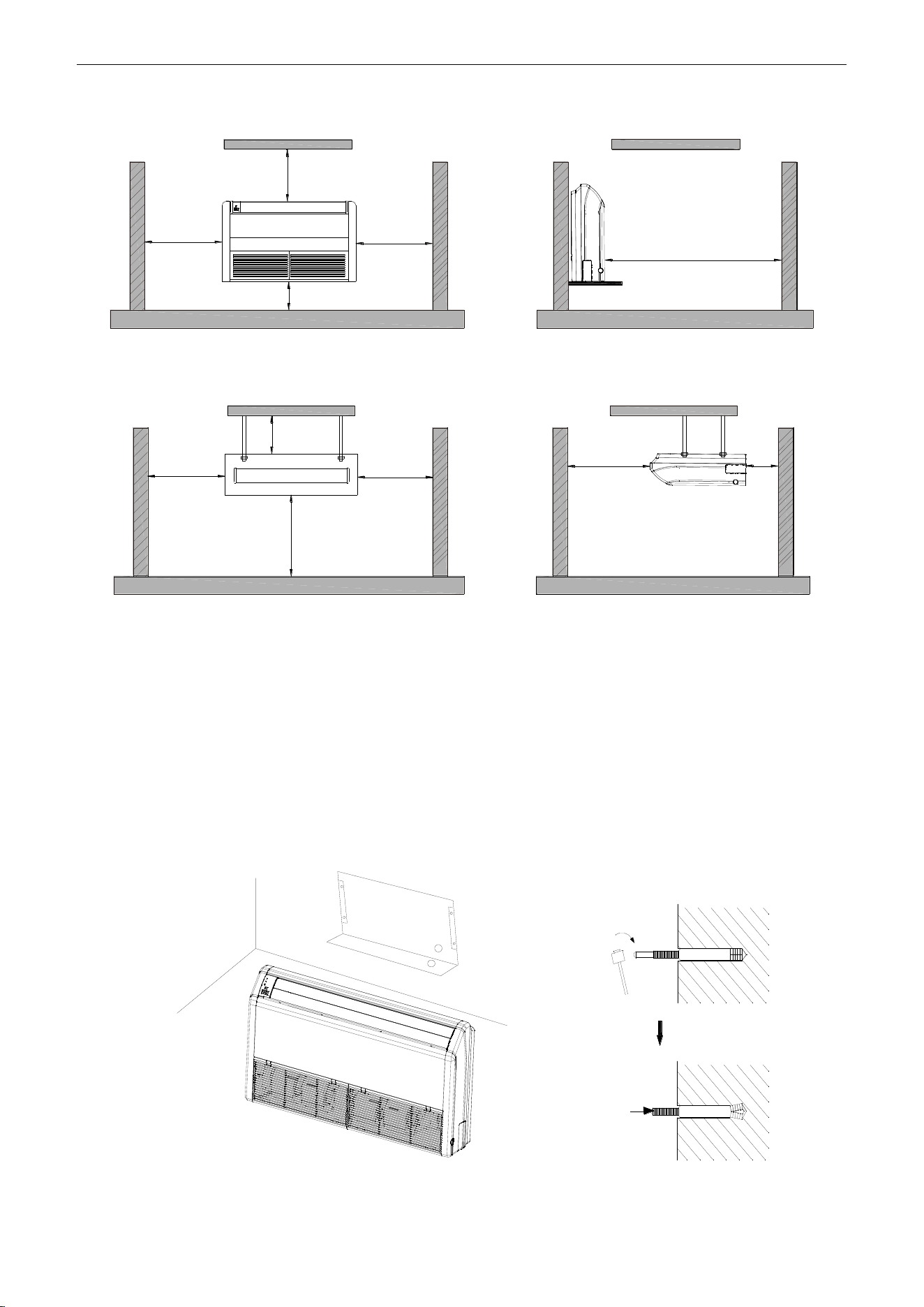
U-Match Series DC Inverter Service Manual
63
Floor type
>600mm
(23-5/8inch)
>300mm(11-3/4inch)
>1000mm(39-3/8inch)
>1500mm(59inch)
>600mm
(23-5/8inch)
Ceiling type
>600mm
(23-5/8inch)
>600mm
(23-5/8inch)
>200mm
(7-7/8inch)
>2300mm
(90-1/2inch)
>1500mm
(59inch)
>300mm
(11-3/4inch)
Figure 3-1-23
(4) Install the unit where the drain pipe can be easily installed.
(5) The space from the unit to the ceiling should be kept as much as possible so as for more
convenient service.
1.2.3 Indoor Unit Installation
(1) Determine the location of the hanger through the paper template, and then remove the paper
template.
Paper template
Anchor bolt
Figure 3-1-24
(2) Insert the anchor bolts into the drilled holes, and drive the pins completely into the anchor bolts
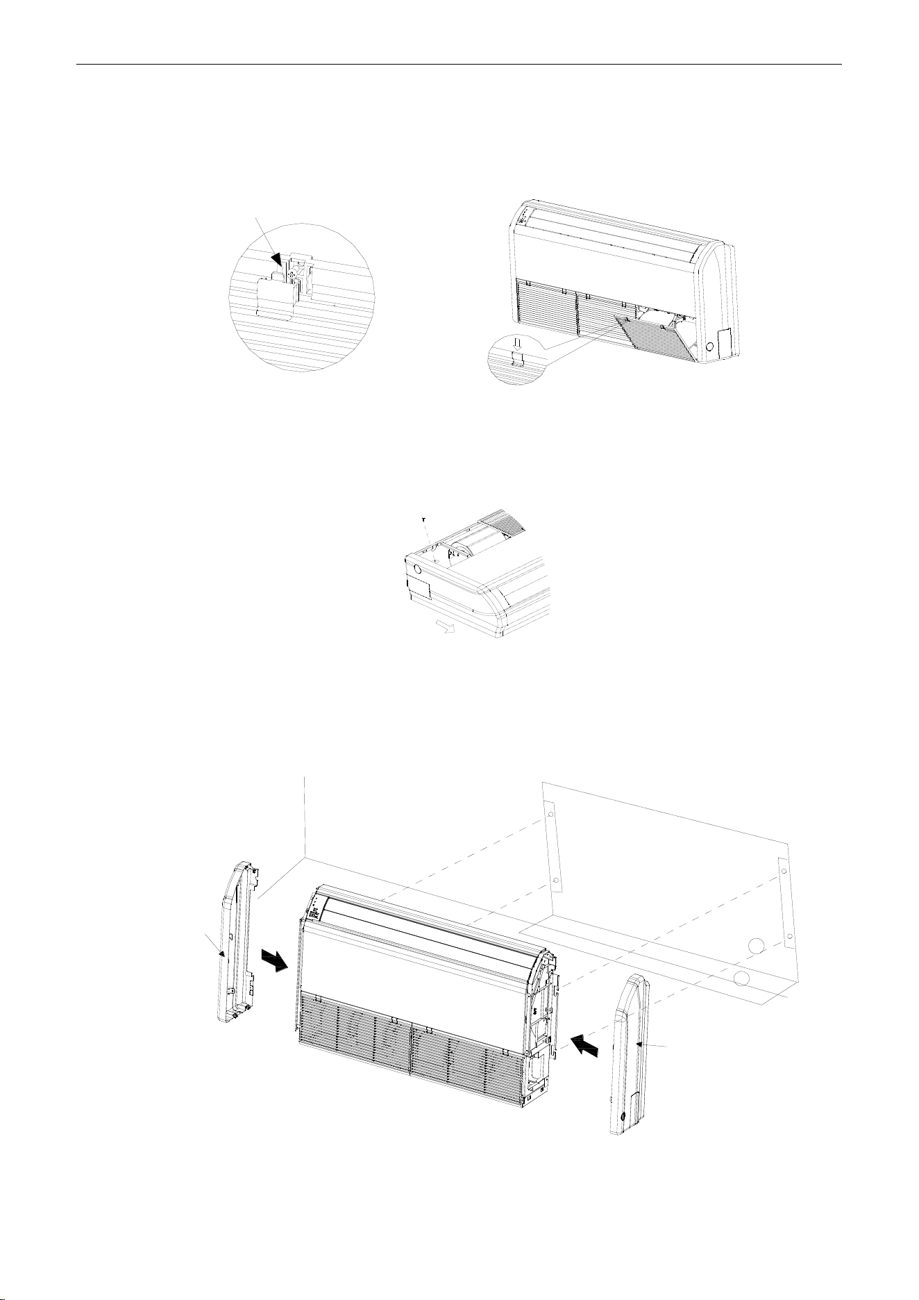
U-Match Series DC Inverter Service Manual
64
with a hammer.
(3) Firstly unfix two buckles on the grille as shown on the picture. Remove the screws under the
buckles by a screwdriver and then open the inlet grille.
Remove the screw
Figure 3-1-25
(4) Remove the screws shown on the picture. Push the side plate as per the arrowed direction and
take it down.
Remove the screw
Figure 3-1-26
(5) Put the hanger bolt into the clasp of the indoor unit and tighten screws on the hanger to prevent
the indoor unit from moving.
(6) Reinstall and tighten the right and left side panels.
Floor type
Left side panel
Wall
Paper template
Right side panel
Figure 3-1-27
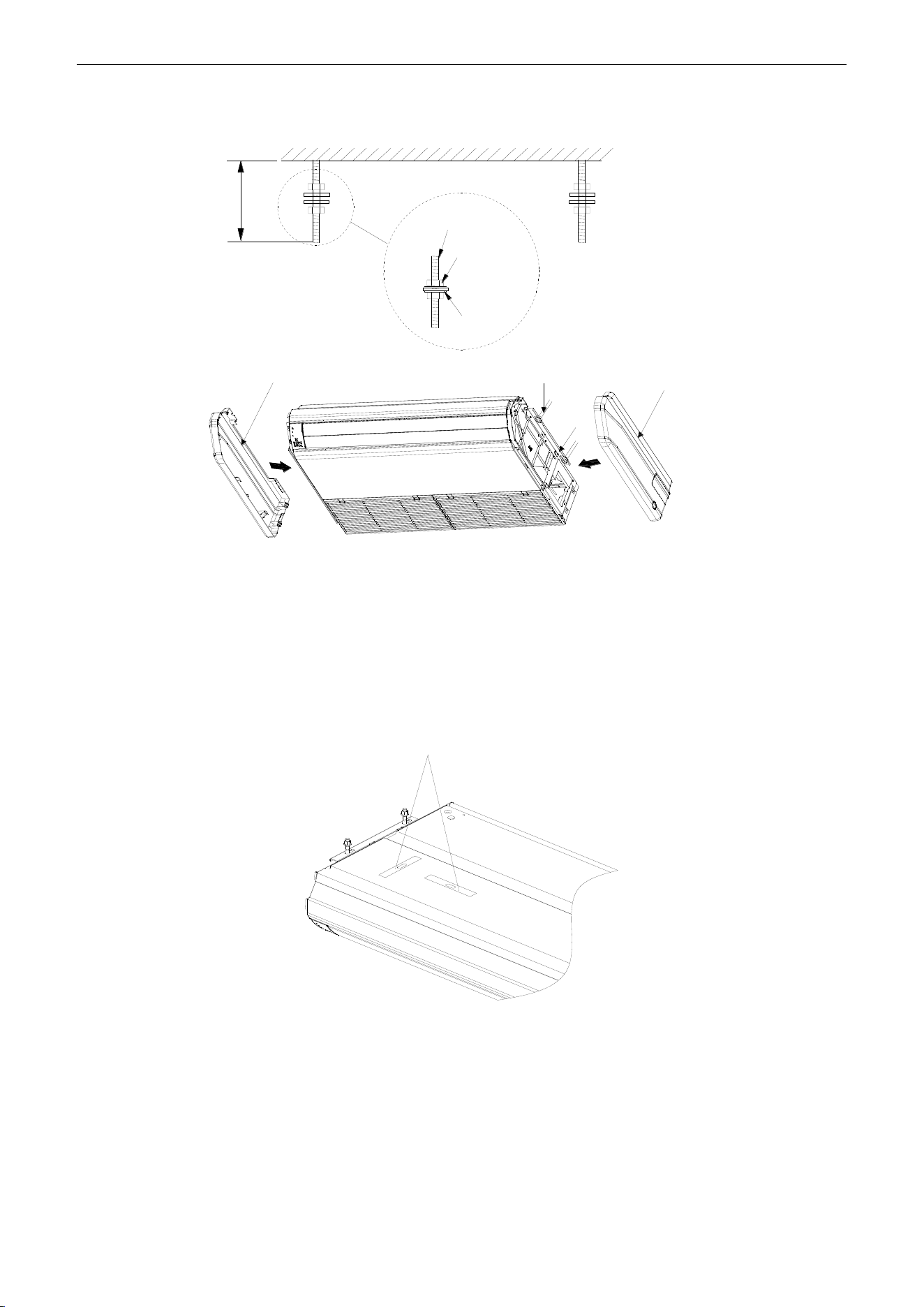
U-Match Series DC Inverter Service Manual
65
Ceiling type
≥40(1-5/8inch)
Ceiling
Suspension
bolt
Nut
Spring
washer
Left side panel
Nut
Hanger
Right side panel
Figure 3-1-28
(7) Adjust the height of the unit to make the drain pipe slant slightly downward so that the drainage
will become much smoother.
1.2.4 Leveling
The water level test must be done after installing the indoor unit to make the unit is horizontal, as
shown below.
Horizontal tester
Figure 3-1-29
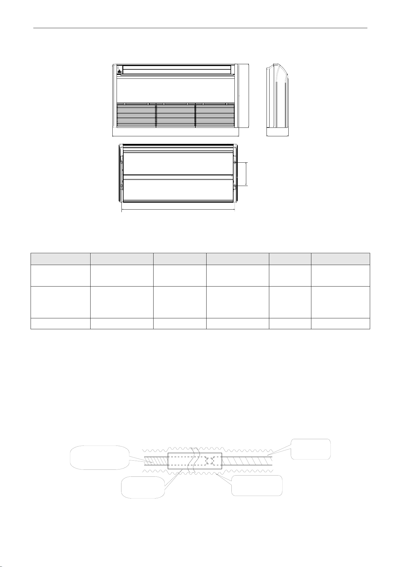
U-Match Series DC Inverter Service Manual
66
1.2.5 Dimension Data
A
H
B
C
D
Figure 3-1-30
Table 3-1-6
Unit: mm (inch)
Model
A
B
C
D
H
UMAT18HP230V1AF
UMAT24HP230V1AF
1220(48)
225(8-7/8)
1160(45-5/8)
280(11)
700(27-1/2)
UMAT30HP230V1AF
UMAT36HP230V1AF
UMAT42HP230V1AF
1420(55-7/8)
245(9-5/8)
1355(53-1/4)
280(11)
700(27-1/2)
UMAT48HP230V1AF
1700(66-7/8)
245(9-5/8)
1635(64-3/8)
280(11)
700(27-1/2)
1.2.6 Drain Piping Work
1.2.6.1 Precautions When Doing the Piping Work
(1) Keep piping as short as possible and slope it downwards at a gradient of at least 1/100 so that air
may not remain trapped inside the pipe.
(2) Keep pipe size equal to or greater than that of the connecting pipe.
(3) Install the drain piping as shown and take measures against condensation. Improperly rigged
piping could lead to leaks and eventually wet furniture and belongings.
Extension drain piping
(commercially
available)
Insulating tube
(commercially
available)
Insulating tape
(accessory)
Indoor unit
drain hose
Figure 3-1-31
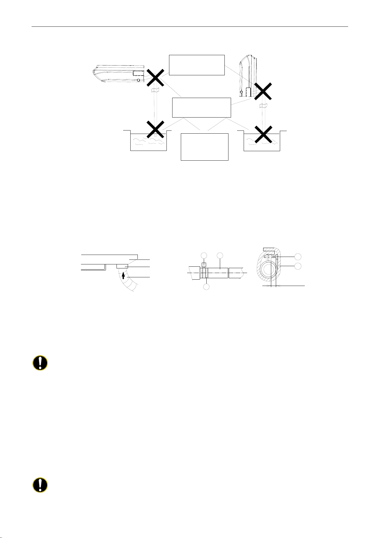
U-Match Series DC Inverter Service Manual
67
(4) Connect the drain hose (Figure 3-1-32).
Drain hose must
slope downward.
Allow no trap to
form in the piping
Do not allow end
of hose to touch
water
Figure 3-1-32
1.2.6.2 Installing the Drain Pipes
(1) For determining the position of the drain hose, perform the following procedures.
(2) Insert the drain pipe to the drain outlet of the unit and then tighten the clamp securely with tape
(Figure 3-1-33).
(3) Connect the extension drain pipe to the drain pipe and then tighten the clamp with tape.
1
2
3
1
2
Drain pan
≤4mm(1/8inch)
Seal
Drain hose
Figure 3-1-33 Figure 3-1-34 Figure 3-1-35
Tighten the clamp until the screw head is less than 4mm (1/8inch) from the hose (Figure 3-1-34).
①- Metal clamp ②- Drain hose ③- Grey tape
Insulate the pipe clamp and the drain hose using heat insulation sponge ( Figure 3-1-35).
①- Metal clamp ②- Insulation sponge
Note:
Step 1 to Step 3 have been finished by the manufacturer.
(4) When drain hose requires extension, obtain an extension hose commercially available.
(5) After connecting the local drain hose, tape the slits of the heat insulation tube.
(6) Connect the drain hose to the local drain pipe. Position the inter connecting wire in the same
direction as the piping.
1.2.6.3 Connecting the Drain Hose
(1) Connect the extension auxiliary pipe to the local piping.
(2) Prepare the local piping at the connection point for the drain pipe, as shown in the installation
drawings.
Note:
Be sure to place the drain hose as shown in the diagram below, in a downward sloping
direction.
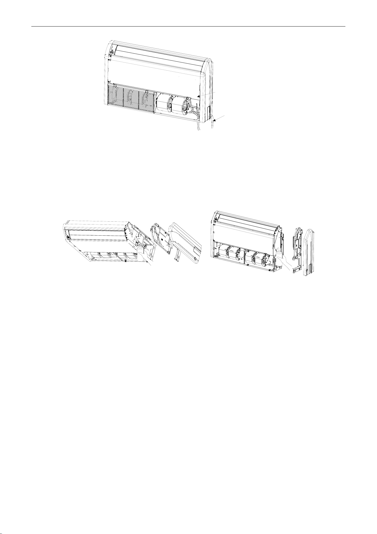
U-Match Series DC Inverter Service Manual
68
Drain pan
Drain hose
①Right side piping②Bottom-right piping
Figure 3-1-36
1.2.6.4 Testing of Drain Piping
(1) After piping work is finished, check if drainage flows smoothly.
(2) As shown in the figure, pour water into the drain pan from the right side to check that water flows
smoothly from the drain hose.
Ceiling type Floor type
Figure 3-1-37
1.3 Installation of Cassette Type
1.3.1 Before Installation
After receiving the machine, please check for any transport damage. If finding any surface or internal
damage, please immediately report to the transport company or equipment company in writing.
After receiving the machine, please check the unit and accessories in reference to the packing list.
Ensure that the model is correct and the machine is in good condition. Please also check if the specification
and quantity of accessory parts are correct.
Determine the correct handling route and methods, thus to avoid damaging the unit or causing
possible hazard. For the sake of protection and safety, it is suggested to move the unit with the packaging
box. Even though it is not permitted to do like this under special occasions, do not remove the packaging
box, thus to avoid loosening or falling during handling.
Confirm if the installing foundation is solid. When this unit is to be installed on the metal section of the
building, make sure that the electrical insulation must comply with applicable standards.
Ensure that the place of installation is far from the area where the inflammable or explosive
substances are stored, thus to avoid possible explosion or fire due to leakage.
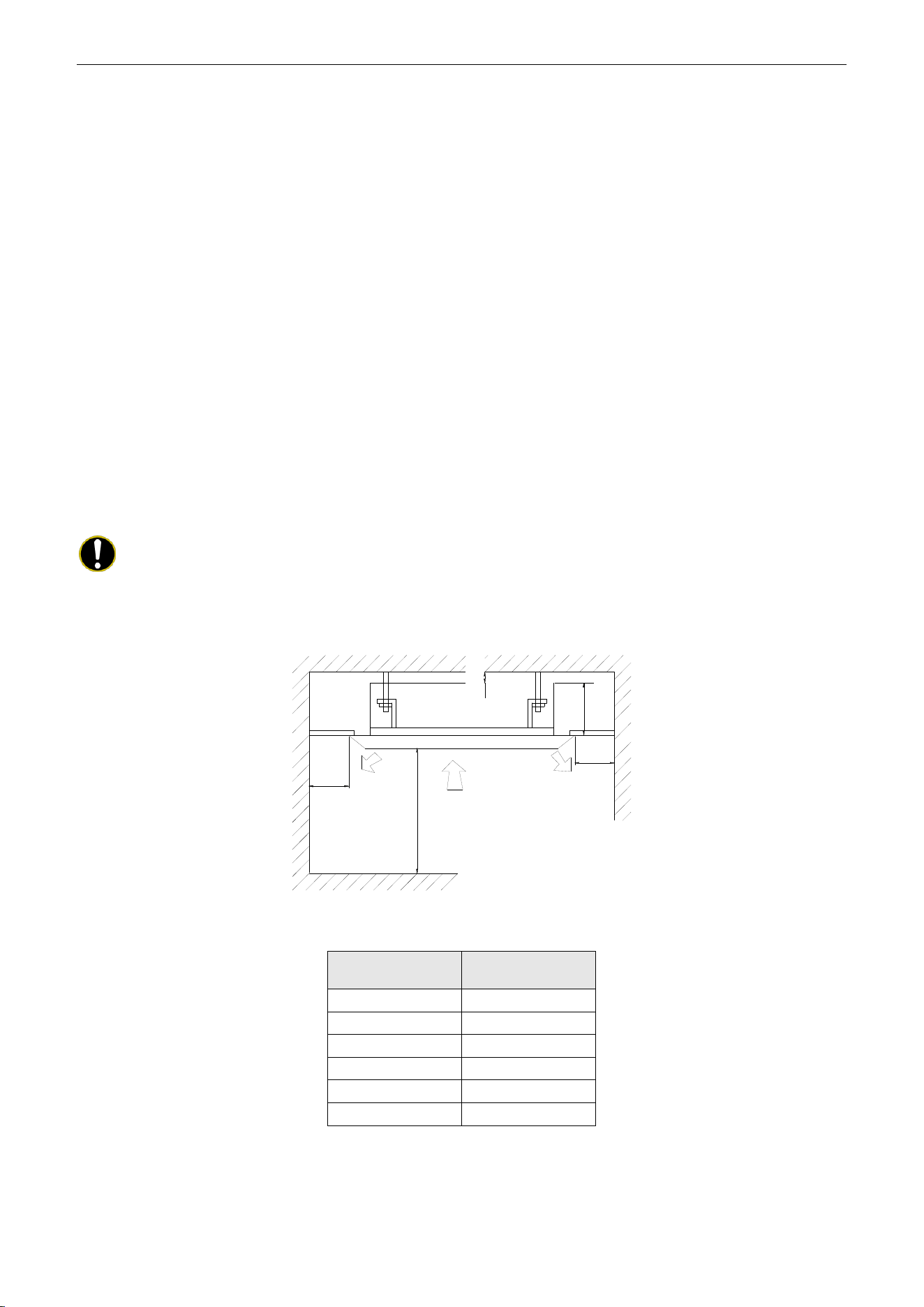
U-Match Series DC Inverter Service Manual
69
1.3.2 Installation Site
Select an installation site where the following conditions are fulfilled and that meets your customer's
approval.
(1) Obstruct should be put away from the intake or outlet vent of the indoor unit so that the airflow can
be blown through all the room.
(2) Make sure that the installation meets the requirement of the schematic diagram of installation
spaces.
(3) Select the place where can stand 4 times of the weight of the indoor unit and would not increase
the operating noise and vibration.
(4) The horizontality of the installation place should be guaranteed.
(5) Select the place where is easy to drain out the condensate water, and connect with outdoor unit.
(6) Make sure that there are enough space for care and maintenance, and the height fall between the
indoor unit and ground is above 1800mm (6ft).
(7) When installing the suspension bolt, check if the installation place can stand 4 times of the weight
of the unit. If not, reinforce it before installation.
Note:
There will be large amount of greasy dirt accumulated on the fan, heat exchanger and water
pump located in the dinning room and kitchen, which would reduce the capacity of the heater exchanger,
lead to leakage and abnormal operation of the water pump.
>20mm(3/4inch)
≥1500mm
(59inch)
≥2500mm(98-3/8inch)
H
≥1500mm
(59inch)
Figure 3-1-38
Table 3-1-7
Models
H
mm (inch)
UMAT18HP230V1AC
255(10)
UMAT24HP230V1AC
260(10-1/4)
UMAT30HP230V1AC
340(13-3/8)
UMAT36HP230V1AC
340(13-3/8)
UMAT42HP230V1AC
340(13-3/8)
UMAT48HP230V1AC
320(12-5/8)
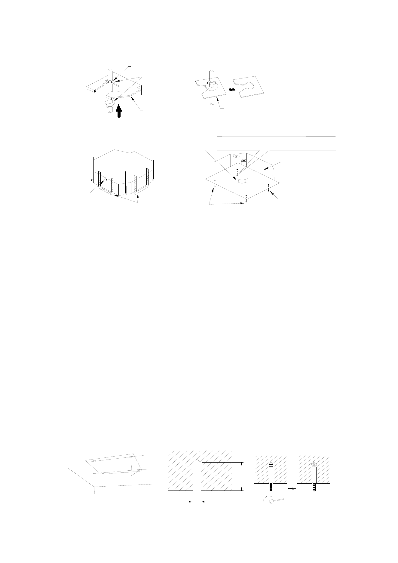
U-Match Series DC Inverter Service Manual
70
1.3.3 Installing the Main Body Unit
Nut(field supplied)
Gas(attachment)
Hoisting stand
Tighten(double nuts)
[Fix the hoisting stand firmly]
Insert
Gasket anchor board(attachment)
[Fix the gasket firmly]
Center of the ceiling
opening
Water level
Polyethylene pipe
Bolt(attachment) [Fix the paper template]
Bolt(attachment)
paper template
One bolt located at one corner of the outlet pipe
should be fixed on one corner of the drainage slot.
Figure 3-1-39
(1) Install the hoisting stand on the hoisting screw by using nuts and gaskets at both the upper and
lower sides of the hoisting stand. To prevent the gasket from breaking off, a gasket anchor board
can be helpful.
(2) Install the paper template on the unit, and fix the drain pipe at the outlet vent.
(3) Adjust the unit to the best position.
(4) Check if the unit is installed horizontally at four directions. If not, the water pump and the float
switch would function improperly and even lead to water leakage.
(5) Remove the gasket anchor board and tighten the nut remained.
(6) Remove the paper template.
1.3.4 Installing the Suspension Bolts
(1) Using the installation template, drill holes for bolts (four holes) (Figure 3-1-40).
(2) Install the bolts to the ceiling at a place strong enough to hang the unit. Mark the bolt positions
from the installation template. With a concrete drill, drill for 12.7mm (1/2inch) diameter holes
(Figure 3-1-41).
(3) Insert the anchor bolts into the drilled holes, and drive the pins completely into the anchor bolts
with a hammer (Figure 3-1-42).
60 to 70mm(2-3/8 to 2-3/4inch)
φ12.7mm(1/2inch)
Drilling position for bolts
Figure 3-1-40 Figure 3-1-41 Figure 3-1-42
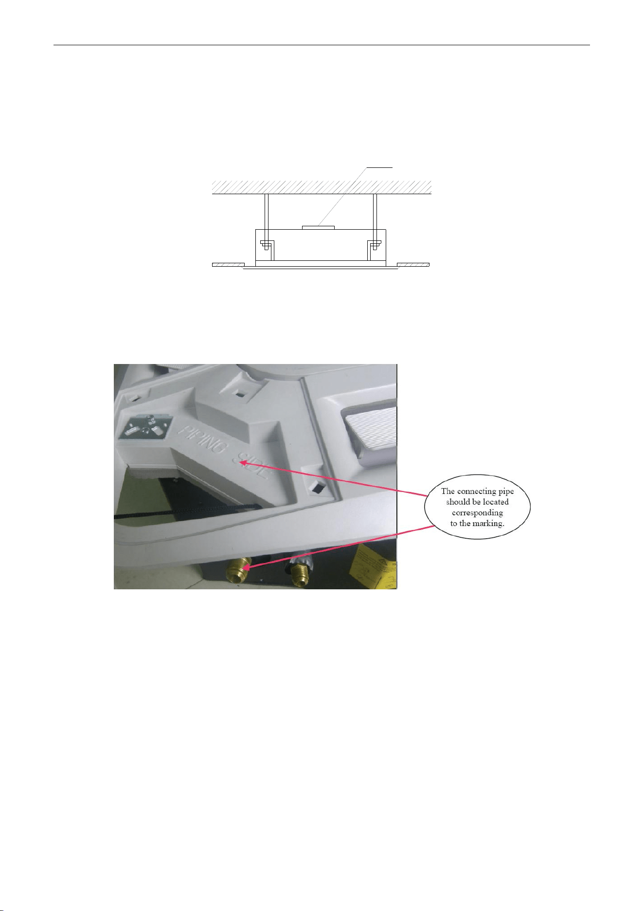
U-Match Series DC Inverter Service Manual
71
1.3.5 Leveling
The water level test must be done after installing the indoor unit to make the unit is horizontal, as
shown below.
Horizontal tester
Figure 3-1-43
1.3.6 The Panel Installation
(1) See the figure below for the relationship of the front panel and the connecting pipe.
Figure 3-1-44
(2) Place the panel at the unit, and latch the hooks beside and opposite the swing flap motor.
(3) Latch other two hooks.
(4) Tighten four hexagonal screws under the latches about 15mm (5/8inch).
(5) Adjust the panel along the direction indicated by the arrow as shown in Figure 3-1-45.
(6) Tighten the screws until the thickness of the sealing material between the panel and the indoor
unit reduces to 5-~8mm (1/4~3/8inch).
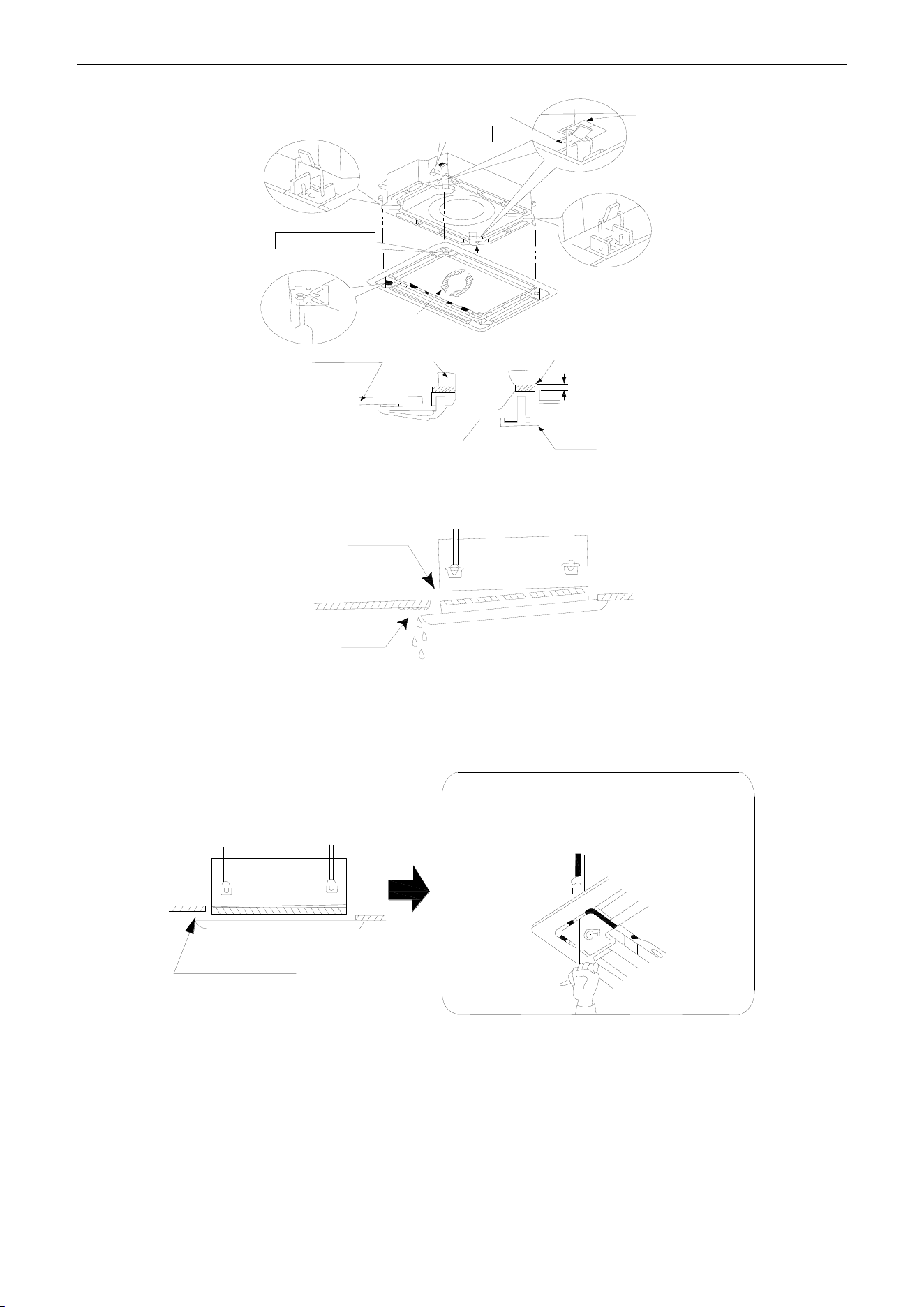
U-Match Series DC Inverter Service Manual
72
5~8mm(1/4~3/8inch)
Latch
Piping position
Hook
Swing flap motor
Indoor unit
Ceiling
Air outlet
Panel
Indoor unit
①
②
②
③
④
⑤
Figure 3-1-45
(7) Improper screwing of the screws may cause the troubles shown in Figure 3-1-46.
Air leak
Condensate
Figure 3-1-46
(8) If gap still exists between ceiling and decoration panel after tightening the screws, readjust the
height of the indoor unit (Figure 3-1-47).
No gap is allowed
Adjustment of the indoor unit body from the holes
in the corner of the panel is possible if the indoor
unit can always be kept horizontal and the drain
pipe etc. will be unaffected.
Figure 3-1-47
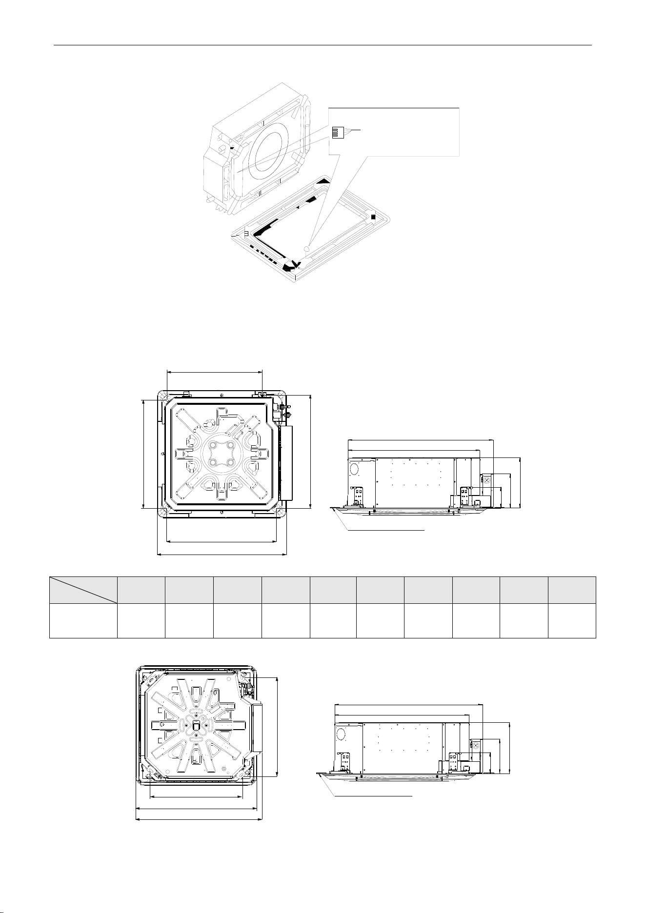
U-Match Series DC Inverter Service Manual
73
(9) Wire the swing flap motor as shown in Figure 3-1-48.
Connect them to the
main body according
to the size of terminals
Figure 3-1-48
1.3.7 Dimension Data
For the units: 18k
A
B
C
D
E
F
G
H
I
J
Bottom face of ceiling
Table 3-1-8 Unit: mm (inch)
Item
Model
A
B
C
D
E
F
G
H
I
J
UMAT18HP230V1AC
670
(26-3/8)
595
(23-1/2)
590
(23-1/4)
575
(22-5/8)
145
(5-3/4)
240
(9-1/2)
665
(26-1/8)
235
(9-1/4)
575
(22-5/8)
505
(19-7/8)
For the units: 24k~42k
A
C
D
I
G
B
E
H
F
Bottom face of ceiling
Table 3-1-9
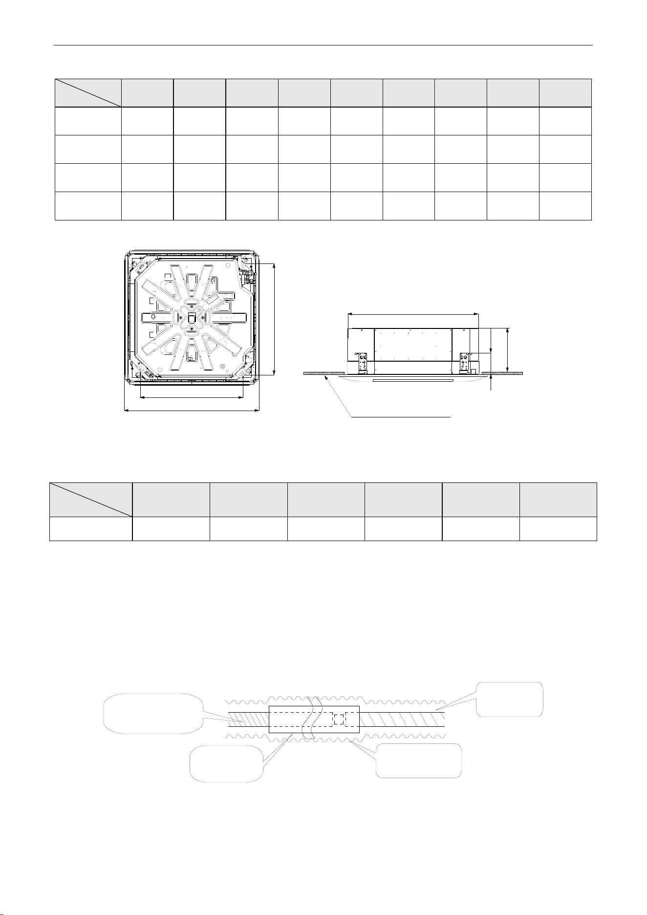
U-Match Series DC Inverter Service Manual
74
Unit: mm (inch)
Item
Model
A
B
C
D
E
F
G
H
I
UMAT24HP230V1AC
950
(37-3/8)
840
(33-1/8)
780
(30-3/4)
680
(26-3/4)
160
(6-1/4)
240
(9-1/2)
915
(36-1/8)
215
(8-1/2)
995
(39-1/8)
UMAT30HP230V1AC
950
(37-3/8)
840
(33-1/8)
780
(30-3/4)
680
(26-3/4)
160
(6-1/4)
320
(12-5/8)
915
(36-1/8)
215
(8-1/2)
995
(39-1/8)
UMAT36HP230V1AC
950
(37-3/8)
840
(33-1/8)
780
(30-3/4)
680
(26-3/4)
160
(6-1/4)
320
(12-5/8)
915
(36-1/8)
215
(8-1/2)
995
(39-1/8)
UMAT42HP230V1AC
950
(37-3/8)
840
(33-1/8)
780
(30-3/4)
680
(26-3/4)
160
(6-1/4)
320
(12-5/8))
915
(36-1/8))
215
(8-1/2)
995
(39-1/8)
For the units: 48k
Bottom face of ceiling
B
A
C
D
E
F
Figure 3-1-49
Table 3-1-10
Unit: mm (inch)
Item
Model
A
B
C
D
E
F
UMAT48HP230V1AC
1040(41)
910(35-7/8)
840(33-1/8)
790(31)
170(6-3/4)
290(11-3/8)
1.3.8 Installation of Drain Piping
(1) Keep piping as short as possible and slope it downwards at a gradient of at least 1/100 so that air
may not remain trapped inside the pipe.
(2) Keep pipe size equal to or greater than that of the connecting pipe.
(3) Install the drain piping as shown and take measures against condensation. Improperly rigged
piping could lead to leaks and eventually wet furniture and belongings.
Extension drain piping
(commercially available)
Insulating tube
(commercially
available)
Indoor unit
drain hose
Insulating tape
(accessory)
Figure 3-1-50
(For the units: 24k~42k Con't)
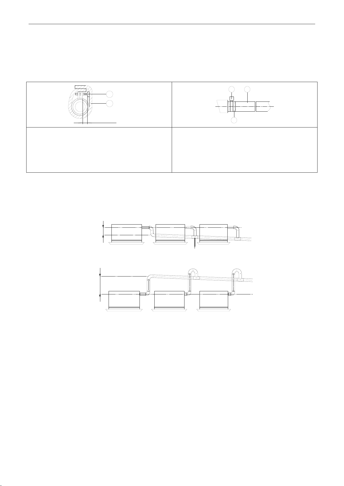
U-Match Series DC Inverter Service Manual
75
1.3.9 Installing the Drain Pipes
(1) Insert the drain pipe to the drain outlet of the unit and then tighten the clamp securely with tape.
(2) Connect the extension drain pipe to the drain pipe and then tighten the clamp with tape.
≤ 4mm(1/8inch)
1
2
1 2
3
Tighten the clamp until the screw head is less then 4mm
(1/8inch) from the hose.
① Metal clamp (accessory)
② Insulation sponge (accessory)
Insulate the pipe clamp and the drain hose using heat
insulation sponge.
① Metal clamp
② Drain hose (accessory)
③ Grey tape (accessory)
(3) When unifying multiple drain pipes, install the pipes as Figure 3-1-51. Select converging drain
pipes whose gauge is suitable for the operating capacity of the unit (take the cassette type unit for
example).
T-joint converging drain pipes
≥100mm(3-7/8inch)
T-joint converging drain pipes
0~1000mm(0~39-3/8inch)
Figure 3-1-51
(4) When the drain hose cannot keep a sufficient gradient, it is necessary to fit a riser pipe (field
supplied) to it.
(5) If the air flow of indoor unit is high, this might cause negative pressure and result in return suction
of outdoor air. Therefore, U-type water trap shall be designed on the drainage side of each indoor
unit (Figure 3-1-52).
(6) Install one water trap for each unit.
(7) Installation of water trap shall consider easy cleaning in the future.
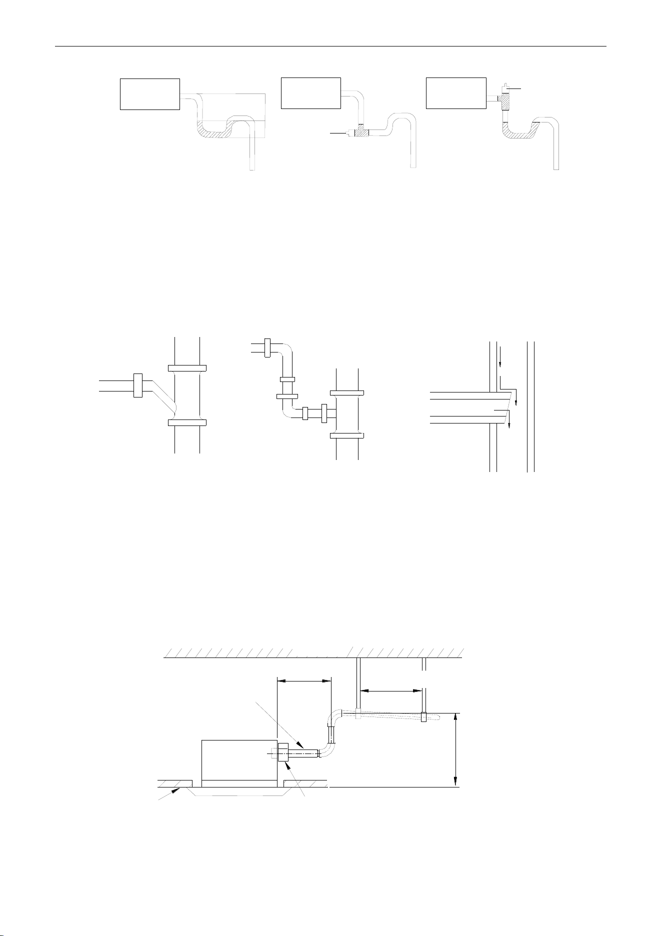
U-Match Series DC Inverter Service Manual
76
Indoor unit
Joint
Indoor unit
Indoor unit
H
H/2
Joint
Figure 3-1-52 Figure 3-1-53 Figure 3-1-54
(8) Connection of drainage branch pipe to the standpipe or horizontal pipe of drainage main pipe.
(9) The horizontal pipe cannot be connected to the vertical pipe at a same height. It can be connected
in a manner as shown below:
NO.1: Attach the 3-way connection of the drainage pipe joint as shown in Figure 3-1-55.
NO.2: Attach the drain elbow as shown in Figure 3-1-56.
NO.3: Attach the horizontal pipe as shown in Figure 3-1-57.
3-way connection of
drainage pipe joint
Connection of drain elbow
Connection of horizontal pipe
Figure 3-1-55 Figure 3-1-56 Figure 3-1-57
1.3.10 Precautions When Doing Riser Piping Work
(1) Make sure that heat insulation work is executed on the following 2 spots to prevent any possible
water leakage due to dew condensation.
1) Connect the drain hose to the drain lift pipe, and insulate them.
2) Connect the drain hose to the drain outlet on the indoor unit, and tighten it with the clamp.
Drain lift pipe
≤1000mm(39-3/8inch)
≤300mm(11-3/4inch)
1000~1500mm(39-3/8~59inch)
Drain hose (attachment)
Ceiling
Clamp (attachment)
Hoisting stand
Roof
Figure 3-1-58
(2) Make sure the lift pipe is at most 280mm (11inch).
(3) Stand the lift pipe vertically, and make sure it is not further than 300mm (11-3/4inch) from the
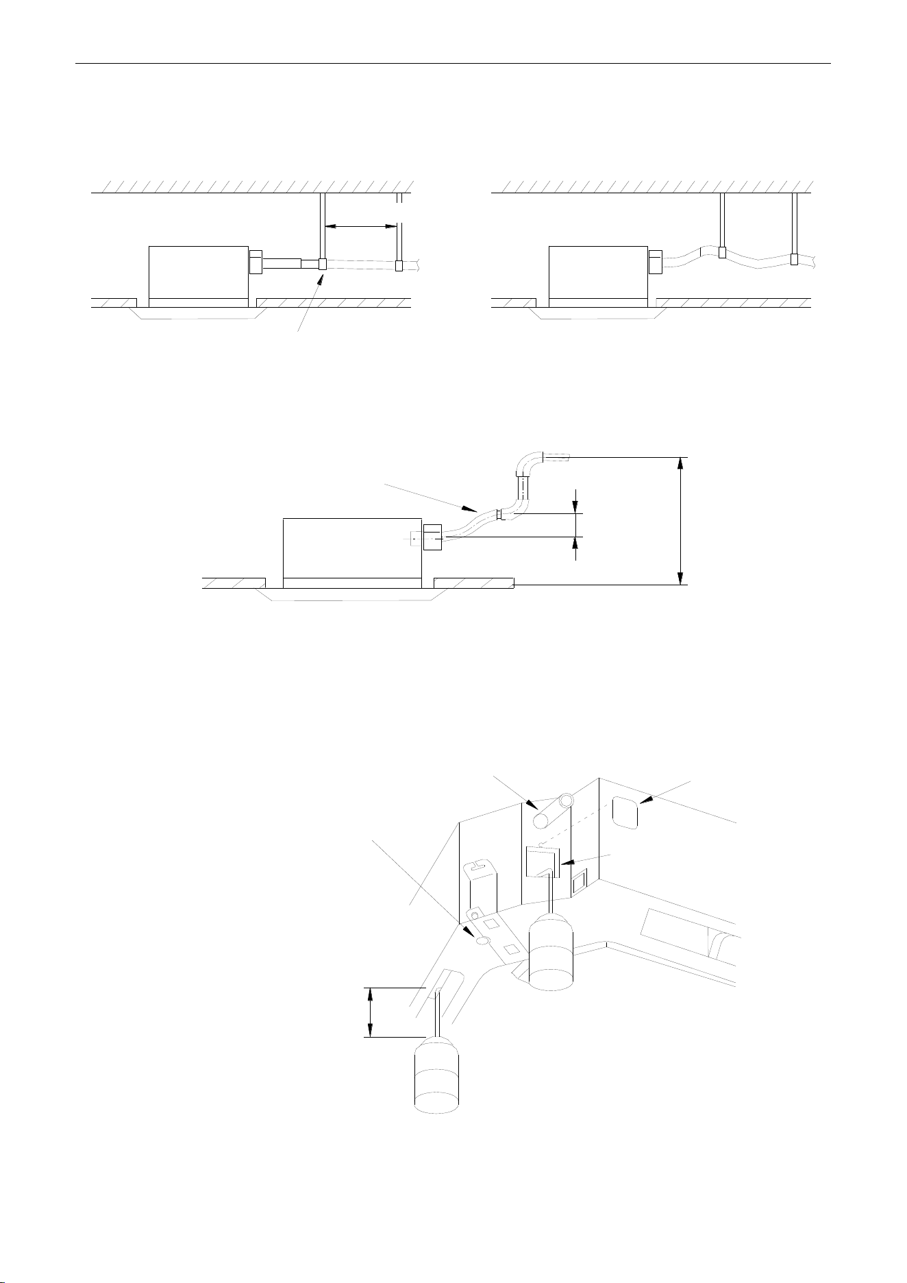
U-Match Series DC Inverter Service Manual
77
base of the drain outlet.
(4) Secure a downward gradient of 1/100 or more for the drain pipe. To accomplish this mount
supporting brackets at an interval of 1~1.5m (3-2/7~5feet).
1~1.5m(3-2/7~5feet)
× (wrong)
√ (Correct) 1/100 or more gradient
Figure 3-1-59
(5) The incline of attached drain hose should be 75mm (3inch) or less so that the drain outlet does
not have to withstand additional force.
≤75mm(3inch)
≤1000mm(39-3/8inch)
Drain hose(attachment)
Figure 3-1-60
1.3.11 Testing of Drain Piping
After piping work is finished, check if drainage flows smoothly. Shown in the Figure 3-1-61, Add
approximately 1liter of water slowly into the drain pan and check drainage flow during COOL running.
Drain hose Test hole cover
Test hole
<Immiting water from the rest hole>
Plastic water pot [The length of
the pipe should be about
100mm(3-7/8inch)].
<Immiting water from the outlet vent terminal>
Above 100mm(3-7/8inch)
Drain vent for repair use (plastic stopper
is included) (drain the water in waterspoit
by this outlet vent)
Figure 3-1-61
U-Match Series DC Inverter Service Manual
78
2 OUTDOOR UNIT INSTALLATION
2.1 Before Installation
After receiving the machine, please check for any transport damage. If finding any surface or internal
damage, please immediately report to the transport company or equipment company in writing.
After receiving the machine, please check the unit and accessories in reference to the packing list.
Ensure that the model is correct and the machine is in good condition. Please also check if the specification
and quantity of accessory parts are correct.
Determine the correct handling route and methods, thus to avoid damaging the unit or causing
possible hazard. For the sake of protection and safety, it is suggested to move the unit with the packaging
box. Even though it is not permitted to do like this under special occasions, do not remove the packaging
box, thus to avoid loosening or falling during handling.
Confirm if the installing foundation is solid. When this unit is to be installed on the metal section of the
building, make sure that the electrical insulation must comply with applicable standards.
Ensure that the place of installation is far from the area where the inflammable or explosive
substances are stored, thus to avoid possible explosion or fire due to leakage.
2.2 Installation Site
①. Install the unit where it will not be tilted by more than 5°.
②. During installation, if the outdoor unit has to be exposed to strong wind, it must be fixed securely.
If possible, do not install the unit where it will be exposed to direct sunlight. (If necessary, install a blind
that does not interfere with the air flow.)
(1) Install the outdoor unit in a place where it will be free from being dirty or getting wet by rain as
much as possible.
(2) Install the outdoor unit where it is convenient to connect with the indoor unit.
(3) Install the outdoor unit where the condensate water can be drained out freely during heating
operation.
(4) Do not place animals and plants in the path of the warm air.
(5) Take the air conditioner weight into account and select a place where noise and vibration are
small.
(6) Install the outdoor unit where is capable of withstanding the weight of the unit and generates as
less noise and vibration as possible.
(7) Provide the space shown in Figure 3-2-1, so that the air flow is not blocked. Also for efficient
operation, leave three of four directions of peripheral constructions open.
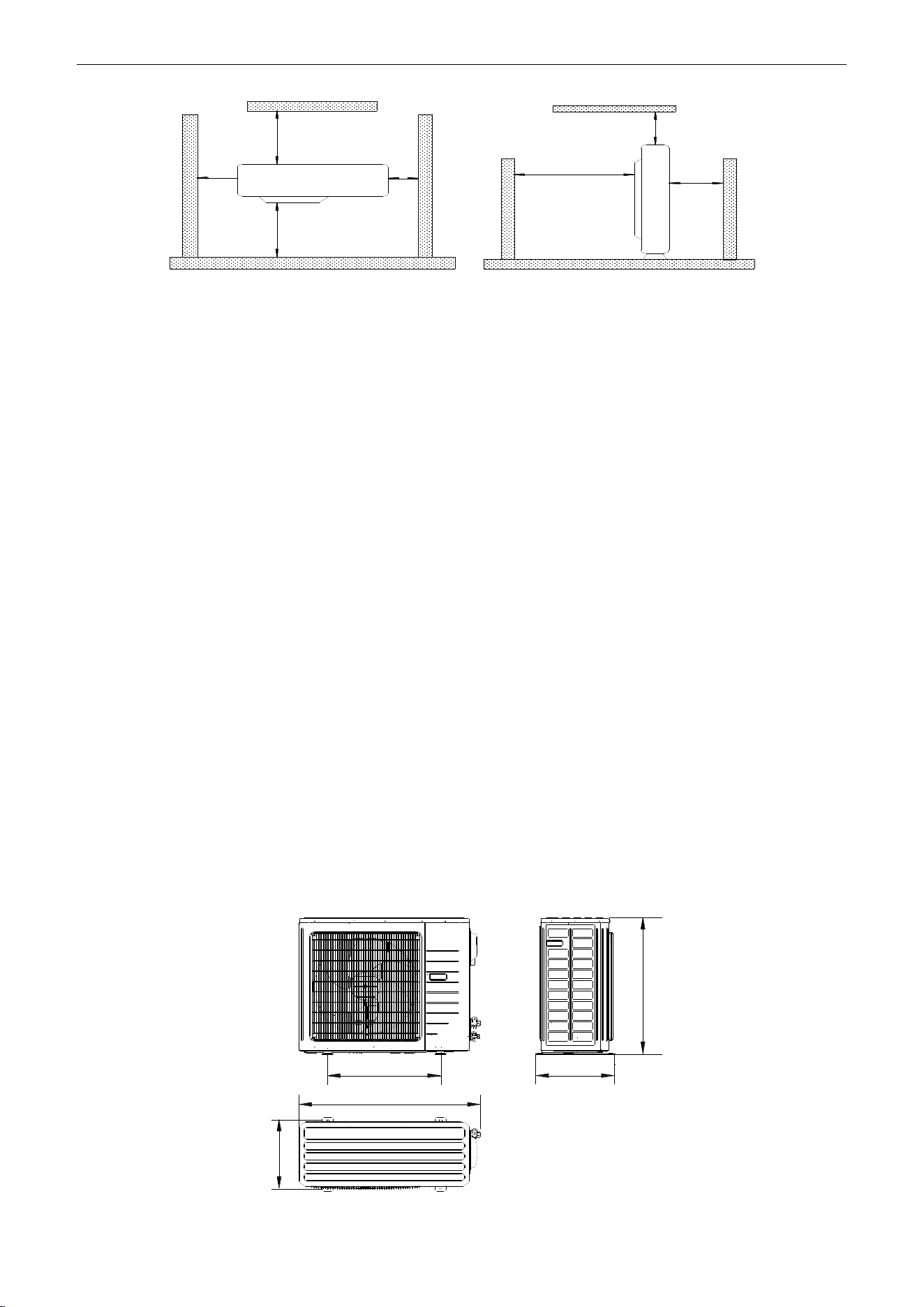
U-Match Series DC Inverter Service Manual
79
>500mm
(1-2/3feet)
>2000mm
(6-5/9feet)
>500mm
(1-2/3feet)
>500mm
(1-2/3feet)
>500mm
(1-2/3feet)
>2000mm
(6-5/9feet)
>1000mm
(3-2/7feet)
Figure 3-2-1
2.3 Caution for Installation
The outdoor unit shall be so installed that the air discharged out of the outdoor unit will not flow back
and that enough space shall be maintained around the machine for repair;
The installing position shall be in good ventilation, so that the machine can breathe and exhaust
enough air. Ensure that there is no obstruction at the inlet and outlet of the machine. If any, please remove
the obstructions blocking the air inlet and outlet.
If the outdoor unit is installed on concrete or solid ground, it shall be fixed by using M10 bolts and nuts.
And ensure that the machine is kept vertical and horizontal.
The outdoor unit must be lifted by using the designated lift hole. During lifting, take care to protect the
air conditioner and avoid knocking the metal parts, thus to prevent rusting in the future.
To meet the noise and vibration requirements, the outdoor unit shall be installed by using rubber
damping pad or spring damper.
To install the drainage pipe, please insert the drainage joint to the drainage hole on the outdoor
chassis and connect a drainage pipe on the drainage joint. (The installing height of outdoor unit shall be at
least 5cm (2inch) if drainage joint is to be used).
To insert the pipe through the wall, the wall-cross tube must be installed.
The installing dimension shall comply with the installation requirements in these instructions. The
outdoor unit must be fixed at the installing position.
The installation shall be done by specialist technicians.
2.4 Dimension Data
D
A
B
C
E
Figure 3-2-2
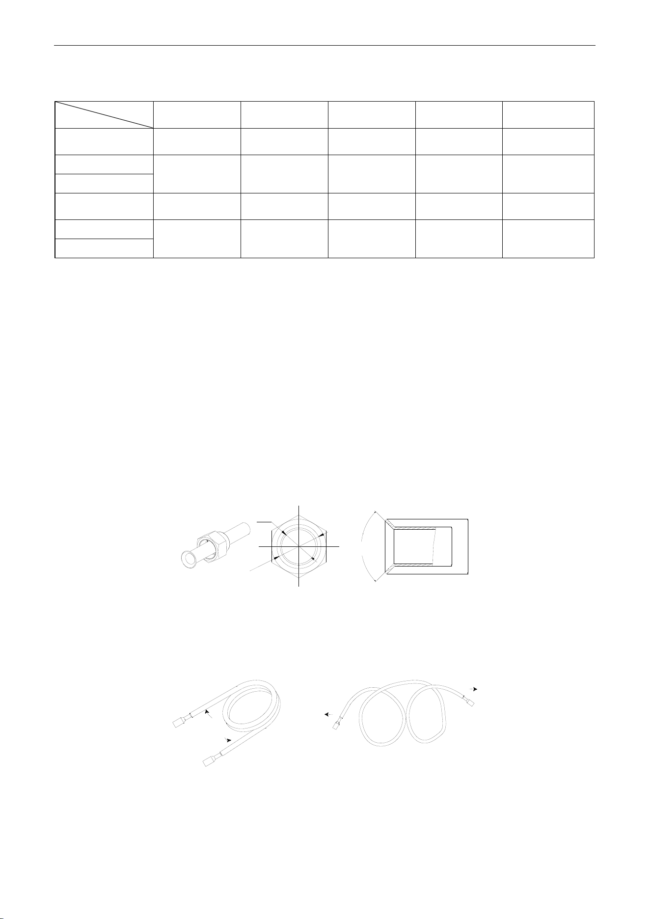
U-Match Series DC Inverter Service Manual
80
Table 3-2-1
Unit: mm (inch)
Item
Model
A
B
C
D
E
UMAT18HP230V1AO
955
(37-5/8)
395
(15-5/8)
700
(27-1/2)
560
(22)
360
(14-1/8)
UMAT24HP230V1AO
980
(38-5/8)
425
(16-3/4)
790
(31-1/8)
610
(24)
390
(15-1/2)
UMAT30HP230V1AO
UMAT36HP230V1AO
1105
(43-5/8)
440
(17-3/8)
1100
(43-1/4)
630
(24-7/8)
400
(15-3/4)
UMAT42HP230V1AO
960
(37-3/4)
410
(16-1/4)
1350
(53-1/8)
570
(22-1/2)
375
(14-3/4)
UMAT48HP230V1AO
3 REFRIGERATION PIPING WORK
3.1 Refrigeration Piping Work Procedures and Caution in Connecting
3.1.1 Flare Processing
(1) Cut the connection pipe with the pipe cutter and remove the burrs.
(2) Hold the pipe downward to prevent cuttings from entering the pipe.
(3) Remove the flare nuts at the stop valve of the outdoor unit and inside the accessory bag of the
indoor unit, then insert them to the connection pipe, after that, flare the connection pipe with a
flaring tool.
(4) Check if the flare part is spread evenly and there are no cracks (see Figure 3-3-1).
d2
d1
d1
d2
90°±1°
Figure 3-3-1
3.1.2 Bending Pipes
(1) The pipes are shaped by your hands. Be careful not to collapse them.
Extend the pipe by unwinding it
√
×
Figure 3-3-2
(2) Do not bend the pipes in an angle more than 90°.
(3) When pipes are repeatedly bent or stretched, the material will harden, making it difficult to bend or
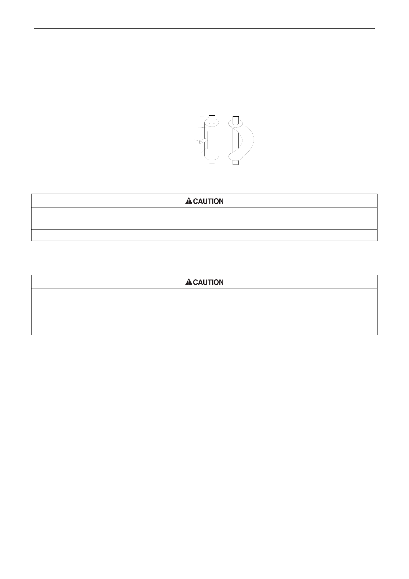
U-Match Series DC Inverter Service Manual
81
stretch them any more. Do not bend or stretch the pipes more than three times.
(4) When bending the pipe, do not bend it as is. The pipe will be collapsed. In this case, cut the heat
insulating pipe with a sharp cutter as shown in Figure 3-3-3, and bend it after exposing the pipe.
After bending the pipe as you want, be sure to put the heat insulating pipe back on the pipe, and
secure it with tape.
Pipe
Cutter
Cutt line
Heat insulating
pipe
Figure 3-3-3
①. To prevent breaking of the pipe, avoid sharp bends. Bend the pipe with a radius of curvature of 150mm (5-7/8inch)
or over.
②. If the pipe is bent repeatedly at the same place, it will break.
3.1.3 Connecting the Pipe at the Indoor Unit Side
Detach the caps and plugs from the pipes.
①. Be sure to apply the pipe against the port on the indoor unit correctly. If the centering is improper, the flare nut
cannot be tightened smoothly. If the flare nut is forced to turn, the threads will be damaged.
②. Do not remove the flare nut until the connection pipe is to be connected so as to prevent dust and impurities from
coming into the pipe system.
When connecting the pipe to the unit or removing it from the unit, please do use both the spanner and
the torque wrench (Figure 3-3-4).
When connecting, smear both inside and outside of the flare nut with refrigeration oil, screw it hand
tight and then tighten it with the spanner.
Refer to Table 3-3-1 to check if the wrench has been tightened properly (too tight would mangle the nut
and lead to leakage).
Examine the connection pipe to see if it leaks, then take the treatment of heat insulation, as shown in
the Figure 3-3-4.
Use the medium-sized sponge to insulate the coupler of the gas pipe.
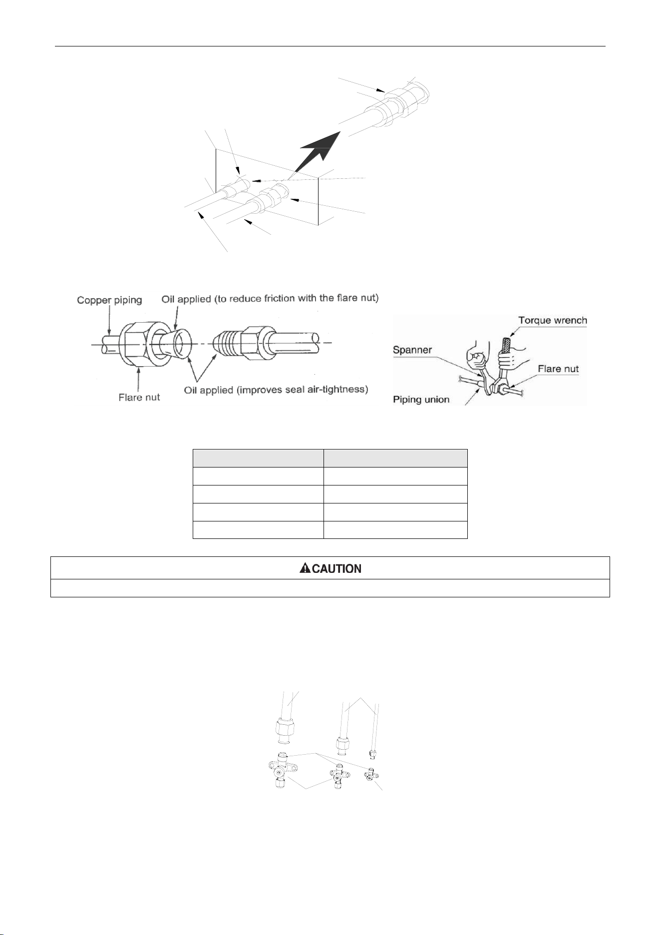
U-Match Series DC Inverter Service Manual
82
Sponge
Threaded fastener(×4)
Liquid pipe
Gas inlet pipe
Heat insulation sheath
(for the gas tube)
Heat insulation sheath
(for the liquid tube)
Figure 3-3-4
Table 3-3-1 Flare nut tightening torque
Pipe Diameter
Tightening Torque
6mm (1/4inch)
15~30N·m (11~22ft.-1b.)
9.5mm (3/8inch)
35~40N·m (26~29ft.-1b.)
12.7mm (1/2inch)
45~50N·m (33~37ft.-1b.)
16mm (5/8inch)
60~65N·m (44~48ft.-1b.)
Be sure to connect the gas pipe after connecting the liquid pipe completely.
3.1.4 Connecting the Pipe at the Outdoor Side Unit
Tighten the flare nut of the connection pipe at the outdoor unit valve connector. The tightening method
is the same as that as at the indoor side.
Gas pipe
Liquid pipe
Pipe
coupling
or
or
3-way valve 2-way valve
Figure 3-3-5
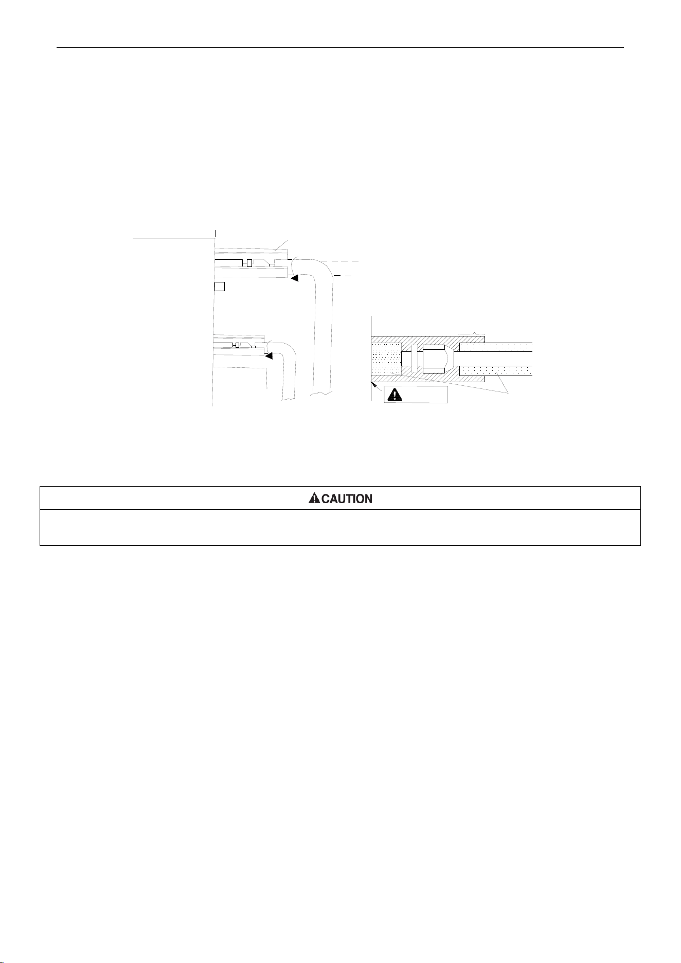
U-Match Series DC Inverter Service Manual
83
3.1.5 Checking the Pipe Connections for Gas Leaking
For both indoor and outdoor unit side, check the joints for gas leaking by the use of a gas leakage
detector without fail when the pipes are connected.
3.1.6 Heat Insulation on the Pipe Joints (Indoor Side Only)
Stick coupler heat insulation (large and small) to the place where connecting pipes.
Front outlet
Coupler heat
insulation (small)
on the pipe
Liquid pipe
Gas pipe
Reference A
Coupler heat insulation
(large) on the pipe
Heat insulation pipe
Reference A:
Cover this portion with heat
insulating material also without fail
No gap
Figure 3-3-6
3.1.7 Vacuum and Gas Leakage Inspection
Do not purge the air with refrigerants but use a vacuum pump to vacuum the installation! There is no extra refrigerant in the
outdoor unit for air purging!
3.1.7.1 Vacuum
(1) Remove the caps of the liquid valve, gas valve and also the service port.
(2) Connect the hose at the low pressure side of the manifold valve assembly to the service port of
the unit’s gas valve, and meanwhile the gas and liquid valves should be kept closed in case of
refrigerant leak.
(3) Connect the hose used for evacuation to the vacuum pump.
(4) Open the switch at the lower pressure side of the manifold valve assembly and start the vacuum
pump. Meanwhile, the switch at the high pressure side of the manifold valve assembly should be
kept closed, otherwise evacuation would fail.
(5) The evacuation duration depends on the unit’s capacity, generally, 20 minutes for the 18k units,
30 minutes for the 24k/30k/36k units, 45 minutes for the 42k/48k units. And verify if the pressure
gauge at the low pressure side of the manifold valve assembly reads -1.0MPa (145psig), if not, it
indicates there is leak somewhere. Then, close the switch fully and then stop the vacuum pump.
(6) Wait for some time to see if the system pressure can remain unchanged, 3 minutes for the
18k/24k units, 10 minutes for the 30k/36k/42k/48k units. During this time, the reading of the
pressure gauge at the low pressure side can not be larger than 0.005MPa (0.72psig).
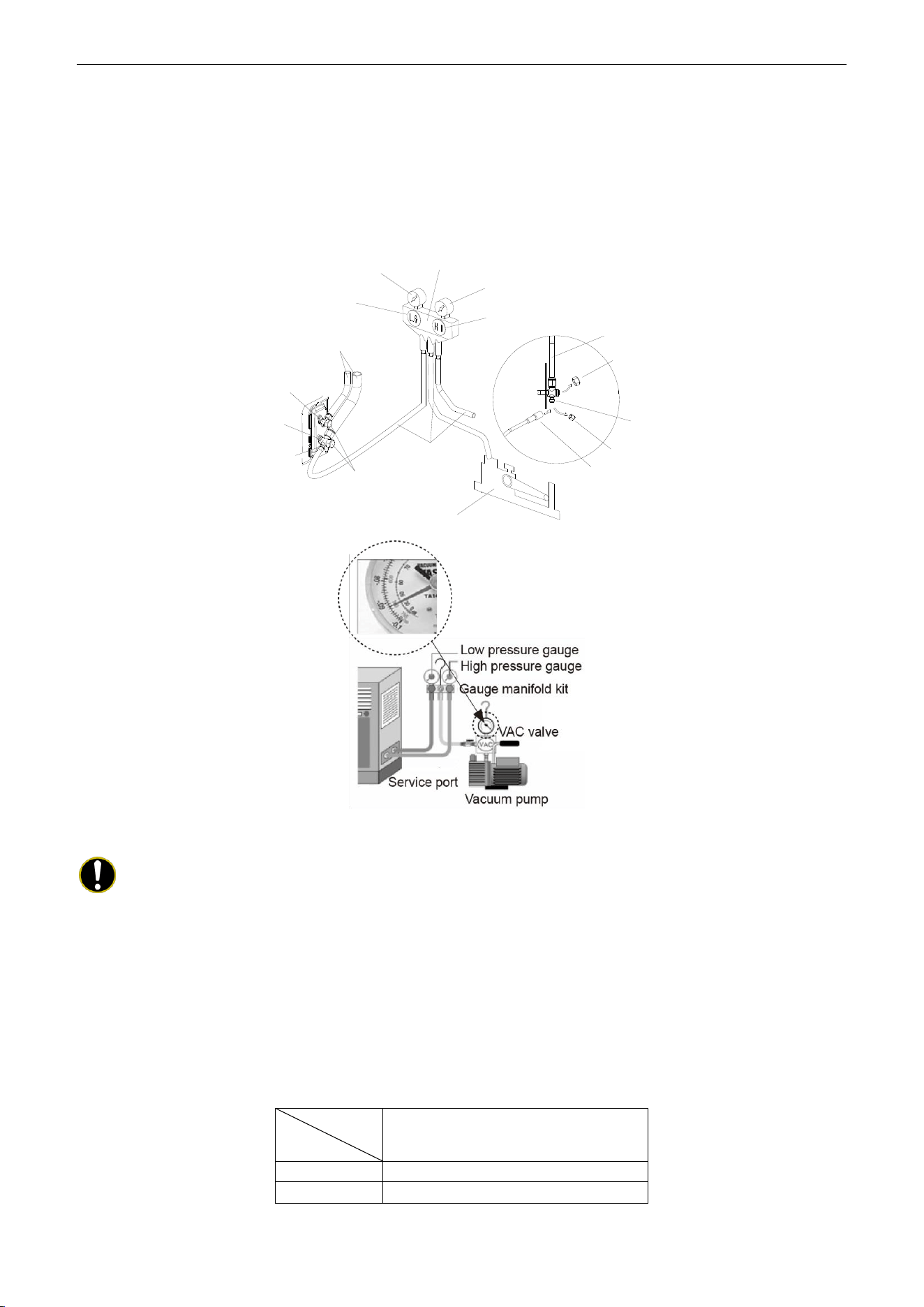
U-Match Series DC Inverter Service Manual
84
(7) Slightly open the liquid valve and let some refrigerant go to the connection pipe to balance the
pressure inside and outside of the connection pipe, so that air will not come into the connection
pipe when removing the hose. Note that the gas and liquid valve can be opened fully only after the
manifold valve assembly is removed.
(8) Place back the caps of the liquid valve, gas valve and also the service port.
Hose with the valve pin
gauge manifold
Pressure gauge (Low-pressure)
Pressure gauge (Hi-pressure)
Switch (Low-pressure)
Switch (Hi-pressure)
Connection pipe (to indoor unit)
Liquid valve
Gas valve
Service port
Cap
Hose
Vacuum pump
Cap
Service pipe
Cap
Connection pipe
Figure 3-3-7
Note:
For the large-sized unit, it has the service port for both the gas valve and the liquid valve.
During evacuation, it is available to connect two hoses of the manifold valve assembly to two service ports
to quicken the evacuating speed.
3.1.7.2 Additional Charge
Refrigerant suitable for a piping length of 7.6m (25feet) is charged in the outdoor unit at the factory.
When the piping is longer than 7.6m (25feet), additional charging is necessary.
For the additional amount, see Table 3-3-2.
Table 3-3-2
Item
Model
Additional Refrigerant Amount for
Extra Pipe
18k
45g per 1.5 m (1.6 ounce per 5 feet )
24k~48k
90g per 1.5 m (3.2 ounce per 5 feet )
When the height difference between the indoor unit and outdoor unit is larger than 10m (32-4/5feet),
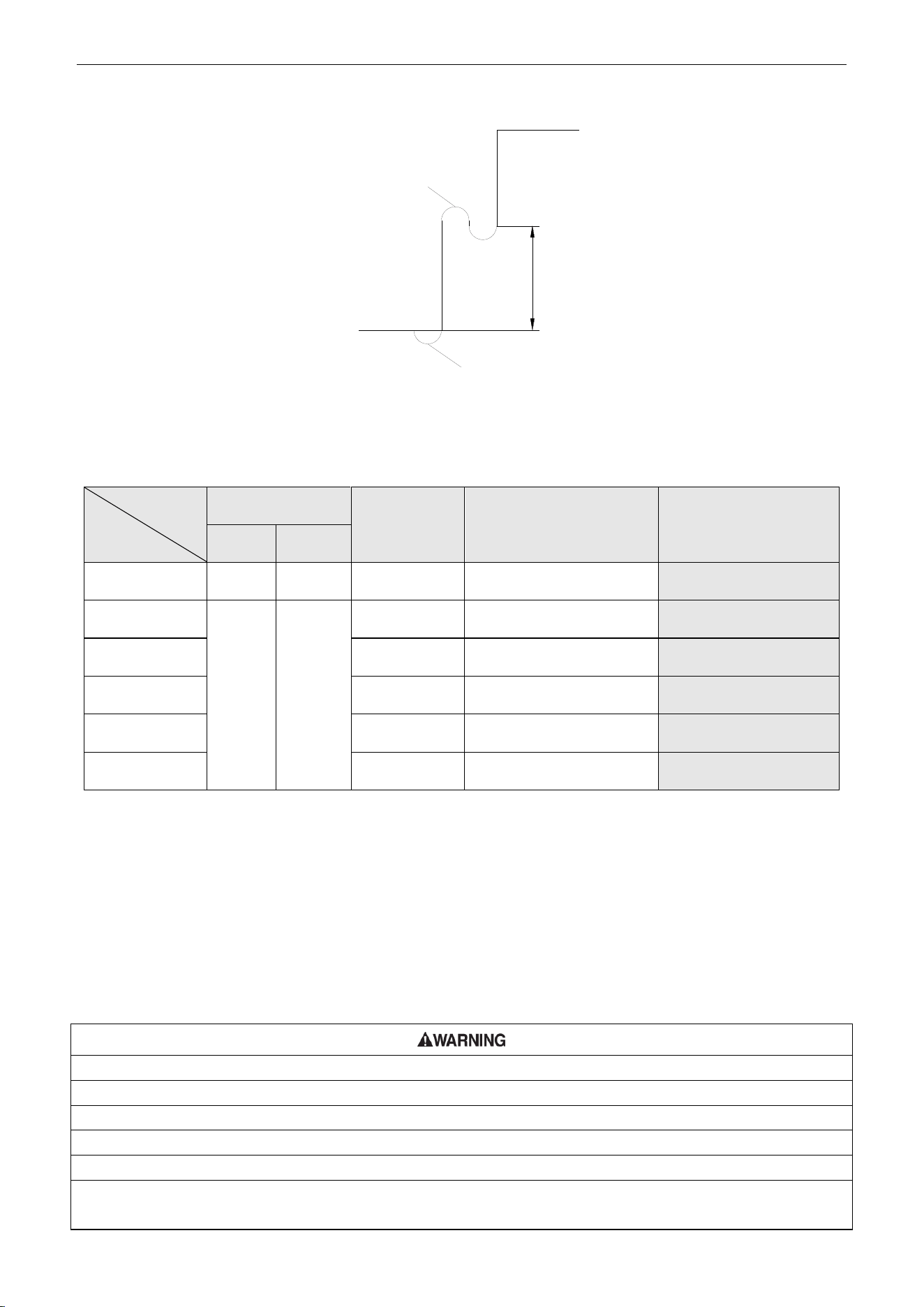
U-Match Series DC Inverter Service Manual
85
an oil bend should be employed for every 6m (19-2/3 feet).
Oil bend
Indoor
Outdoor
6m(19-2/3feet)
Oil bend
Figure 3-3-8
3.2 Specification of Connection Pipe
Table 3-3-3
Item
Model
Size of Fitting Pipe
mm (inch)
Max. Pipe
Length
m (feet)
Max. Height Difference
between Indoor Unit and
Outdoor Unit
m (feet)
Drainage pipe(Outer
Diameter × wall
thickness)
mm (inch)
Liquid
Gas
UMAT18HP230V1AO
6(1/4)
12.7(1/2)
50(164)
15(49-1/5)
Φ17X1.75
(Φ5/8 X 7/100)
UMAT24HP230V1AO
9.5(3/8)
16(5/8)
50(164)
15(49-1/5)
Φ17X1.75
(Φ5/8 X 7/100)
UMAT30HP230V1AO
50(164)
15(49-1/5)
Φ17X1.75
(Φ5/8 X 7/100)
UMAT36HP230V1AO
50(164)
15(49-1/5)
Φ17X1.75
(Φ5/8 X 7/100)
UMAT42HP230V1AO
50(164)
15(49-1/5)
Φ17X1.75
(Φ5/8 X 7/100)
UMAT48HP230V1AO
70(229.7)
15(49-1/5)
Φ17X1.75
(Φ5/8 X 7/100)
The connection pipe should be insulated with proper water-proof insulating material.
The pipe wall thickness shall be 0.5~1.0mm (1/50~1/25inch) and the pipe wall shall be able to
withstand the pressure of 6.0MPa (870psig). The longer the connecting pipe, the lower the cooling and
heating effect performs.
4 ELECTRIC WIRING WORK
4.1 Wiring Precautions
①. Before obtaining access to terminals, all supply circuits must be disconnected.
②. The rated voltage of the unit is as shown as Table 1-4-1 and Table 1-4-2
③. Before turning on, verify that the voltage is within the 187~252V range (for single phrase units).
④. Always use a special branch circuit and install a special receptacle to supply power to the air conditioner.
⑤. Use a special branch circuit breaker and receptacle matched to the capacity of the air conditioner.
⑥. The special branch circuit breaker is installed in the permanent wiring. Always use a circuit that can trip all the poles
of the wiring and has an isolation distance of at least 3mm (1/8inch) between the contacts of each pole.
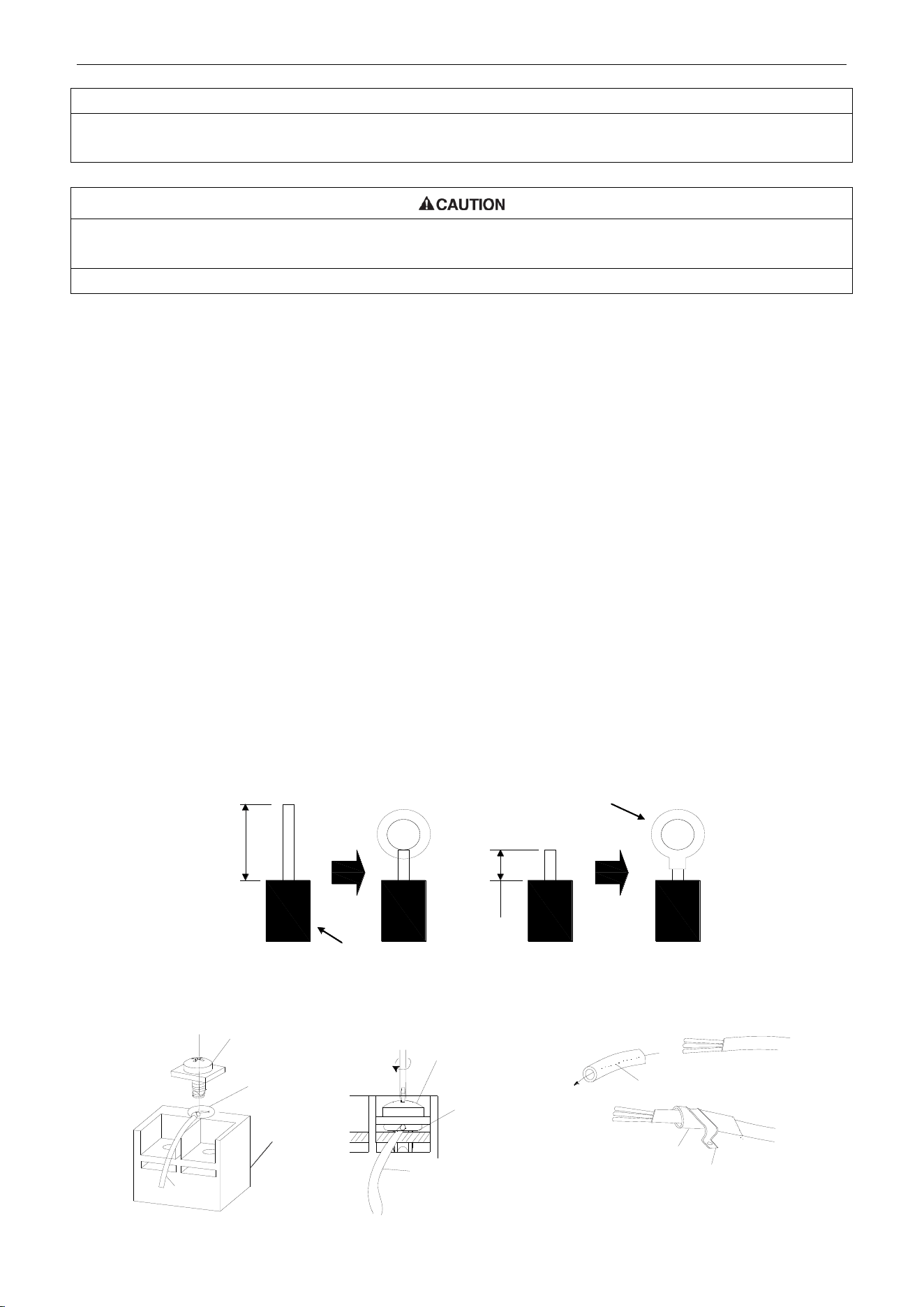
U-Match Series DC Inverter Service Manual
86
⑦. Perform wiring work in accordance with standards so that the air conditioner can be operated safely and positively.
⑧. Install a leakage special branch circuit breaker in accordance with the related laws and regulations and electric
company standards.
①. The power source capacity must be the sum of the air conditioner current and the current of other electrical
appliances. When the current contracted capacity is insufficient, change the contracted capacity.
②. When the voltage is low and the air conditioner is difficult to start, contact the power company to raise the voltage.
4.2 Electrical Wiring
(1) For solid core wiring (Figure 3-4-1)
1) Cut the wire end with a wire cutter or wire-cutting pliers, then strip the insulation about 25mm (1
inch).
2) Using a screwdriver, remove the terminal screw(s) on the terminal board.
3) Using pliers, bend the solid wire to form a loop suitable for the terminal screw.
4) Shape the loop wire properly, place it on the terminal board and tighten securely with the
terminal screw using a screwdriver.
(2) For strand wiring (Figure 3-4-1).
1) Cut the wire end with a wire cutter or wire-cutting pliers, then strip the insulation about 10mm
(3/8inch).
2) Using a screwdriver, remove the terminal screw (s) on the terminal board.
3) Using a round terminal fastener or pliers, securely clamp a round terminal to each stripped wire
end.
4) Position the round terminal wire, and replace and tighten the terminal screw with a screwdriver
(Figure 3-4-2).
10mm(3/8inch)
A Solid wire B Strand wire
Solderless
terminal
Insulation layer
25mm(1inch)
Figure 3-4-1
Screw with
special washer
Round
terminal
Terminal
board
Screw with
special washer
Round
terminal
Wire
Wire
Insulation tube
Insulation tube
Cord clamp
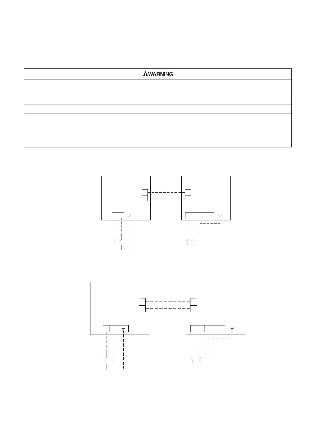
U-Match Series DC Inverter Service Manual
87
Figure 3-4-2 Figure 3-4-3
(3) How to fix connection cord and power cord by cord clamp
After passing the connection cord and power cord through the insulation tube, fasten it with the cord
clamp (Figure 3-4-3).
①. Before starting work, check that power is not being supplied to the indoor unit and outdoor unit.
②. Match the terminal block numbers and connection cord colors with those of the indoor unit side. Erroneous wiring
may cause burning of the electric parts.
③. Erroneous wiring may cause burning of the electric parts
④. Connect the connection cords firmly to the terminal block. Imperfect installation may cause a fire.
⑤. Always fasten the outside covering of the connection cord with cord clamps. (If the insulator is not clamped, electric
leakage may occur.)
⑥. Always connect the ground wire.
(4) Electric wiring between the indoor and outdoor units
Duct Type Unit:
Single-phase units (18k~30k)
Outdoor Unit
Indoor Unit
1
1
L1
2 2
L2
L1 L2
G
Breaker
Power:208/230V~60Hz
L1 L2
G
Breaker
Power:208/230V~60Hz
L1L2 F
C
O
Single-phase units (36k~48k)
L1 L2
G
Power:208/230V~60Hz
Breaker
Outdoor Unit
1
2
1
2
Indoor Unit
L1 L2
G
Breaker
Power:208/230V~60Hz
L1 L2
L1 L2
F
C
O
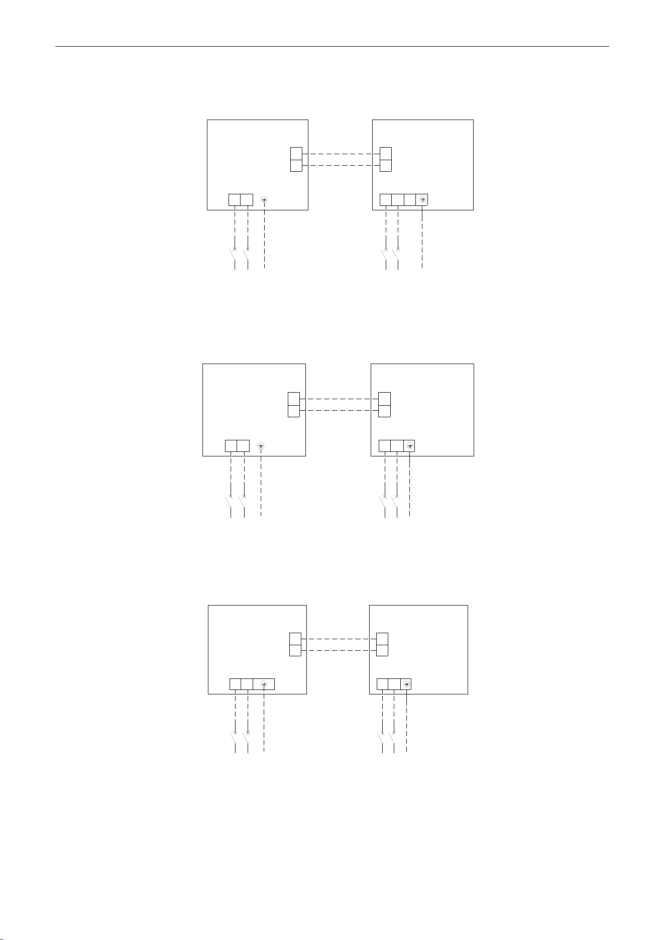
U-Match Series DC Inverter Service Manual
88
Cassette Type Unit:
Single-phase units: 18k
Outdoor unit
Indoor unit
Breaker
Breaker
Power:208/230V ~ 60Hz
Power:208/230V ~ 60Hz
1
2
1
2
L1
L2
L1
L2
L1
L2
L1
L2
G
G
Single-phase units: 24k~30k
Outdoor unit
Indoor unit
Breaker
Breaker
Power:208/230V ~ 60Hz
Power:208/230V ~ 60Hz
1
2
1
2
L1
L2
L1L2
L1
L2
L1
L2
G
G
Single-phase units: 36k~42k
Outdoor unit
Indoor unit
Breaker
Breaker
Power:208/230V ~ 60Hz
Power:208/230V ~ 60Hz
1
2
1
2
L1
L2
L1L2
L1
L2
L1
L2
G
G
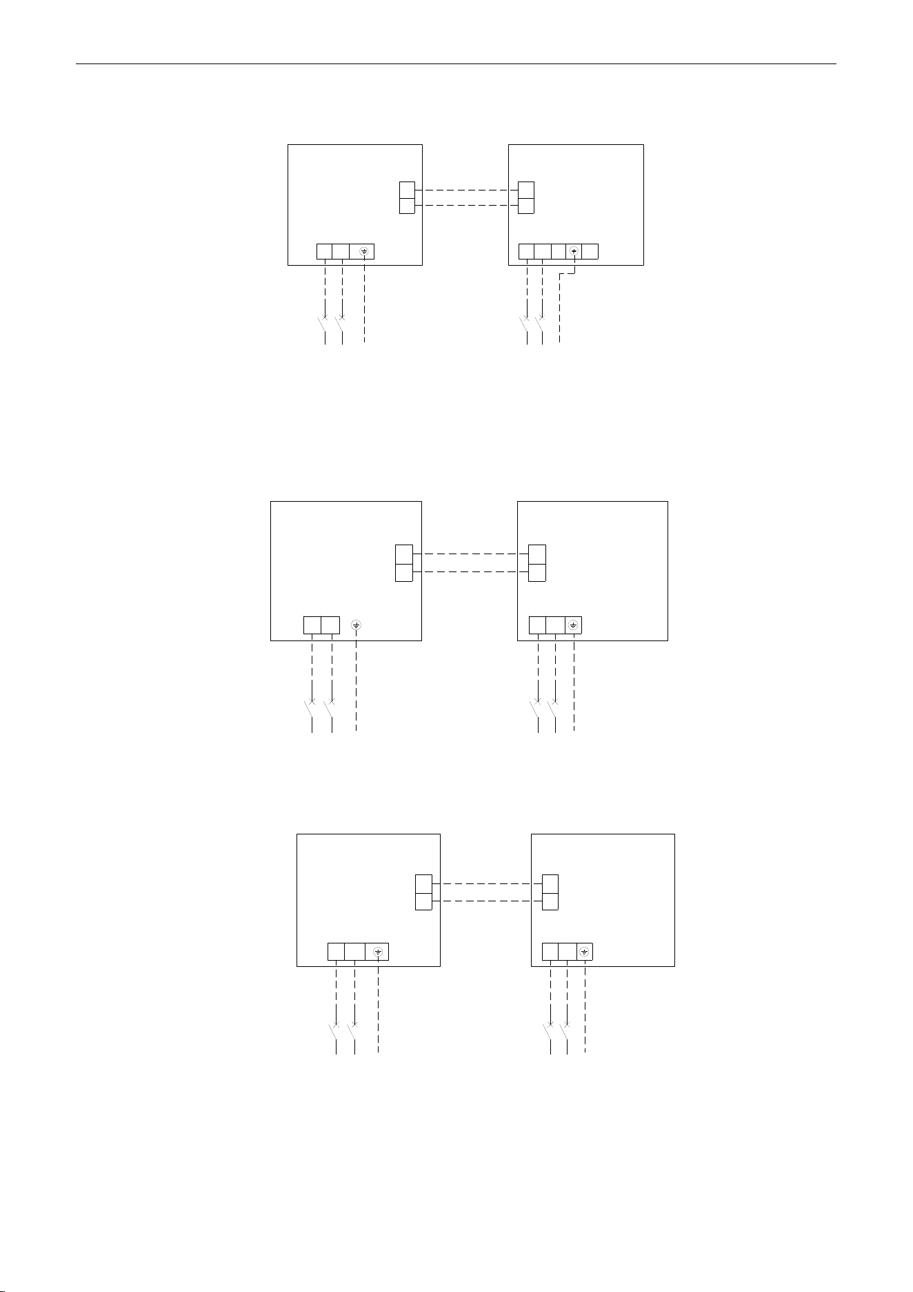
U-Match Series DC Inverter Service Manual
89
Single-phase units: 48k
Outdoor unit
Indoor unit
Breaker
Breaker
Power:208/230V ~ 60Hz
Power:208/230V ~ 60Hz
1
2
1
2
L1
L2
L1
L2
L1
L2
L1
L2
G
G
Floor ceiling Type Unit:
Single-phase units (18k~30k)
G G
Breaker
Breaker
L1
L2
L1
L2
1
2
1
2
L1
L2
L1
L2
Outdoor Unit
Indoor Unit
Power: 208/230V ~ 60Hz Power: 208/230V ~ 60Hz
Single-phase units (36k~48k)
Breaker
Breaker
L1
L2
L1
L2
1
2
1
2
G G
L1
L2
L1
L2
Outdoor Unit
Indoor Unit
Power: 208/230V ~ 60Hz Power: 208/230V ~ 60Hz
Figure 3-4-4
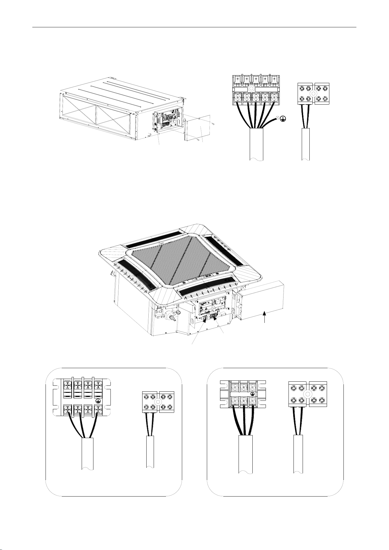
U-Match Series DC Inverter Service Manual
90
(5) Electric wiring of indoor unit side
Remove the electric box cover from the electric box sub-assy and then connect the wire.
Duct Type Unit:
Electric box
sub-assy
Electric box
cover
L1 L2
F C O
H1 H2
1 2
Figure 3-4-5
The F, C, O connect to the COMMOM, CLOSE and OPEN terminal of the fresh air valve respectively.
Cassette Type Unit:
For the units: 18k~42k
Power supply
terminal board
Electric box cover
Communication
terminal board
L1
L2
1
2
H1 H2
18k
L1 L2
H1 H2
1 2
24k~42k
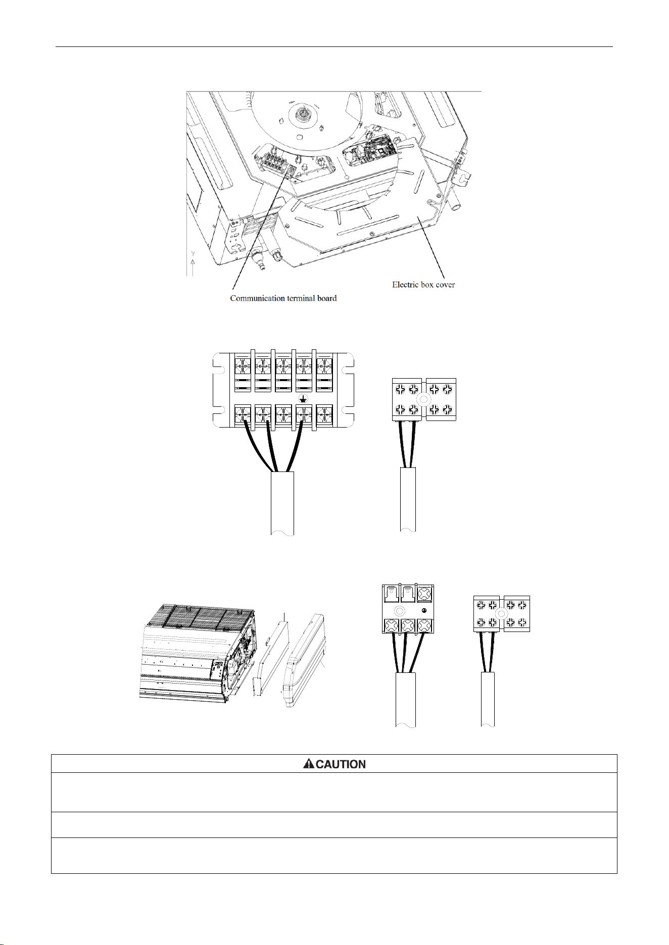
U-Match Series DC Inverter Service Manual
91
For the units: 48k
L1
L2
1
2
H1
H2
Figure 3-4-6
Floor Ceiling Type Unit:
Electric box cover
Left side panel
L1
L2
1
2
H1
H2
Figure 3-4-7
①. The power cord and the wire of the fresh air valve are high-voltage, while the communication cord and connection
wire of the wired controller are low-voltage. They should run separately against electromagnetic interference.
②. The high-voltage and low-voltage lines should pass through the rubber rings at different electric box covers.
③. Do not bundle the connection wire of the wired controller and the communication cord together, or arrange them in
parallel, otherwise improper operation would occur.
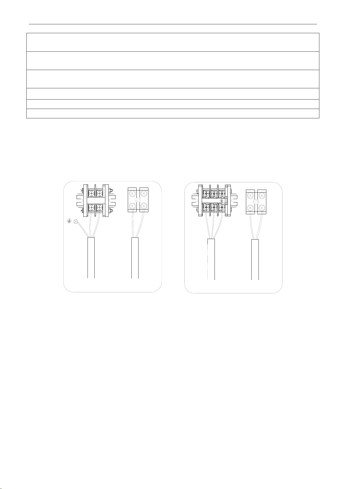
U-Match Series DC Inverter Service Manual
92
④. The high-voltage and low-voltage lines should be fixed separately and securely, with internal big clamps for the
former and small clamps for the latter.
⑤. Tighten the indoor/outdoor connection cord and power cord respectively on the terminal boards with screws. Faulty
connection may cause a fire.
⑥. If the indoor unit connection cord (to the outdoor unit) and power supply are wired incorrectly, the air conditioner
may be damaged.
⑦. Connect the indoor unit connection cord properly based on the corresponding marks as shown in Figure 3 -4-4.
⑧. Ground both the indoor and outdoor units by attaching a ground wire.
⑨. Unit shall be grounded in compliance with the applicable local and national codes.
(6) Electric wiring of outdoor unit side
NOTICE!
When connecting the power supply cord, make sure that the phase of the power supply
matches with the exact terminal board. If not, the compressor will rotate reversely and run improperly.
Remove the big handle (18k~30k) /front board (36k~48k) of the outdoor unit and insert the end of the
communication cord and the power cable into the terminal board.
Single phase:
18k~30k 36k~48k
1
2
1
2
L1 L2
L1 L2
Figure 3-4-8

U-Match Series DC Inverter Service Manual
94
MAINTENANCE
U-Match Series DC Inverter Service Manual
95
MAINTENANCE
1 TROUBLE TABLE
1.1 Main Control Malfunction
Table 4-1-1 Fault Display on Indoor Wired Controller
No.
Error code
Malfunction
name
Origin of
malfunction
signal
Control description
1
E1
High pressure
protection
High pressure
switch
When outdoor unit detects the high pressure switch is cut off for
3s successively, high pressure protection will occur. All the loads
(except the 4-way valve in heating mode) will be switched off. In
this case, all the buttons and remote control signals except
ON/OFF button will be disabled and cannot be recovered
automatically. Switch off the unit or re-energize the unit after
cutting off power to eliminate this protection.
2
E2
Freeze protection
Indoor
evaporator
temperature
sensor
If detecting that the evaporator temperature is lower than
protective temp. value after the unit has been running for a
period of time under cooling or dry mode, the unit will report this
fault, in which case the compressor and outdoor fan motor will be
stopped. The unit will not run until evaporator temperature is
higher than the protective temp. value and the compressor is
stopped for 3min.
3
E3
Low pressure
protection
Low pressure
switch
If it is detected within 30s successively that the low-pressure
switch is cut off under ON or standby state, the unit will report low
pressure protection. If the fault occurs successively 3 times
within 30min, the unit cannot be recovered automatically.
Refrigerant
lacking protection
If the unit reports system refrigerant lacking within 10min after
turning on the unit, the unit will stop operation. If the fault occurs
successively 3 times, the unit cannot be recovered automatically.
Refrigerant
recycling mode
If enter refrigerant recycling mode through special operation, E3
will be displayed. After exiting refrigerant recycling mode, the
code will disappear.
4
E4
Compressor high
discharge
temperature
protection
Compressor
discharge
temperature is
high
If outdoor unit detects that the discharge temperature is higher
than protective temp. value, the unit will report high discharge
temperature protection. If the protection occurs over 6 times, the
unit cannot be recovered automatically. Switch off the unit or
re-energize the unit after cutting off power to eliminate this
protection.
5
E6
Communication
malfunction
Communication
between indoor
and outdoor main
board
If the outdoor unit does not receive data from indoor unit,
communication malfunction will be reported. If there is
communication abnormity between display board and indoor unit,
communication malfunction will be reported too.
6
E8
Malfunction of
indoor fan motor
Indoor fan motor
If the indoor unit does not receive signal from indoor fan motor for
30s successively when the fan motor is operating, indoor fan
motor malfunction will be reported. In this case, the unit can
automatically resume operation after stopping. If the malfunction
occurs 6 times within one hour, the unit cannot be recovered
automatically. Switch off the unit or re-energize the unit after
cutting off power to eliminate this malfunction.
U-Match Series DC Inverter Service Manual
96
No.
Error code
Malfunction
name
Origin of
malfunction
signal
Control description
7
E9
Full water
protection
Water level
switch
If cut-off of water level switch is detected for 8s successively
once energized, the system will enter full water protection. In this
case, switch off the unit and then switch it on to eliminate this
malfunction.
8
F0
Malfunction of
indoor ambient
temperature
sensor at air
return port
Indoor ambient
temperature
sensor
If the indoor ambient temperature sensor is detected of open
circuit or short circuit for 5s successively, indoor ambient
temperature sensor malfunction will be reported. The unit can
automatically resume operation after the malfunction disappears.
If indoor ambient temperature sensor malfunction occurs in fan
mode, only the error code is displayed and the indoor unit can
work normally.
9
F1
Malfunction of
evaporator
temperature
sensor
Evaporator
temperature
sensor
If the indoor evaporator temperature sensor is detected of open
circuit or short circuit for 5s successively, evaporator
temperature sensor malfunction will be reported. The unit can
automatically resume operation after the malfunction disappears.
If evaporator temperature sensor malfunction occurs in fan
mode, only the error code is displayed and the indoor unit can
work normally.
10
F2
Malfunction of
condenser
temperature
sensor
Condenser
temperature
sensor
If the outdoor condenser temperature sensor is detected of open
circuit or short circuit for 5s successively, condenser temperature
sensor malfunction will be reported. The unit can automatically
resume operation after the malfunction disappears. If condenser
temperature sensor malfunction occurs in fan mode, only the
error code is displayed and the indoor unit can work normally.
11
F3
Malfunction of
outdoor ambient
temperature
sensor
Outdoor ambient
temperature
sensor
If the outdoor ambient temperature sensor is detected of open
circuit or short circuit for 5s successively, outdoor ambient
temperature sensor malfunction will be reported. The unit can
automatically resume operation after the malfunction disappears.
If outdoor ambient temperature sensor malfunction occurs in fan
mode, only the error code is displayed and the indoor unit can
work normally.
12
F4
Malfunction of
discharge
temperature
sensor
Discharge
temperature
sensor
If the outdoor discharge temperature sensor is detected of open
circuit or short circuit for 5s successively after the compressor
has been operating for 3min, outdoor discharge temperature
sensor malfunction will be reported. The unit can automatically
resume operation after the malfunction disappears.
13
F5
Malfunction wired
controller
temperature
sensor
Wired controller
If the wired controller detects open circuit or short circuit of its
temperature sensor for 5s successively, wired controller
temperature sensor malfunction will be reported.
14
ee
Malfunction of
outdoor drive
memory chip
Outdoor drive
board
If the memory chip of outdoor drive board is broken, the unit
cannot be started. The unit cannot be recovered automatically. If
the malfunction cannot be eliminated after switching off the unit
and then energizing the unit for several times, please replace the
outdoor drive board.
15
H3
Compressor
overload
protection
Compressor
overload switch
If it is detected within 3s successively that the overload switch is
cut off under ON or standby state, the unit will report overload
protection. If the fault occurs successively 3 times, the unit
cannot be recovered automatically. Switch off the unit or
re-energize the unit after cutting off power to eliminate this
protection.
U-Match Series DC Inverter Service Manual
97
No.
Error code
Malfunction
name
Origin of
malfunction
signal
Control description
16
H4
Overload
protection
Evaporator
temperature,
condenser
temperature
If outdoor unit detects that the tube temperature is higher than
protective temp. value, the unit will report overload protection.
The unit will not restart operation until tube temperature is lower
than the protective temp. value and the compressor is stopped
for 3min. If the protection occurs over 6 times, the unit cannot be
recovered automatically. Switch off the unit or re-energize the
unit after cutting off power to eliminate this protection.
17
H6
Malfunction of
outdoor fan motor
Outdoor fan
motor
If the outdoor unit does not receive signal from outdoor fan motor
for 30s successively when the fan motor is operating, outdoor fan
motor malfunction will be reported. In this case, the unit can
automatically resume operation after stopping. If the malfunction
occurs 6 times within one hour, the unit cannot be recovered
automatically. Switch off the unit or re-energize the unit after
cutting off power to eliminate this malfunction.
18
U7
Direction
changing
malfunction of
4-way valve
4-way valve
After the compressor starts operation in heating mode, if the
outdoor unit detects the difference between evaporator
temperature and indoor ambient temperature is lower than the
protective value for 10min successively, direction changing
malfunction of 4-way valve will be reported and the outdoor unit
will stop operation. The unit can automatically resume operation
in the first two malfunctions. If the malfunction occurs 3 times, the
unit cannot be recovered automatically. Switch off the unit or
re-energize the unit after cutting off power to eliminate this
malfunction.
19
P6
Communication
malfunction
between main
control and drive
Communication
between main
control board and
drive board
If the outdoor main control board does not receive data from
drive board, communication malfunction between main control
and drive will be reported. This malfunction can be eliminated
automatically.
20
EE
Malfunction of
outdoor main
control memory
chip
Outdoor main
control board
If the memory chip of outdoor main control board is broken, the
unit cannot be started. The unit cannot be recovered
automatically. If the malfunction cannot be eliminated after
switching off the unit and then energizing the unit for several
times, please replace the outdoor main control board.
U-Match Series DC Inverter Service Manual
98
1.2 Description of Drive Malfunction
Main board dual 8 numeral tube Display Codes for Outdoor Unit of 18k~48k
Malfunction Item
Indoor Unit Display
Outdoor unit display of dual 8 numeral
tube
DC busbar over-voltage protection
PH
PH
IPM or PFC over-temperature protection
P8
P8
Current sense circuit error
Pc
Pc
IPM or PFC temperature sensor error
P7
P7
Compressor current protection
P5
P5
DC busbar under-voltage protection
PL
PL
Compressor startup failure
Lc
Lc
Drive module reset
P0
P0
Compressor motor desynchronizing
H7
H7
Phase loss
Ld
Ld
Drive-to-main-control communication error
P6
P6
IPM protection
H5
H5
Compressor overload protection
H3
H3
AC current protection (input side)
PA
PA
Charging circuit error
PU
PU
PFC protection
HC (48k only)
HC (48k only)
DC fan error
H6
H6
Input AC voltage abnormality
PP
PP
Driving board memory chip error
ee
ee
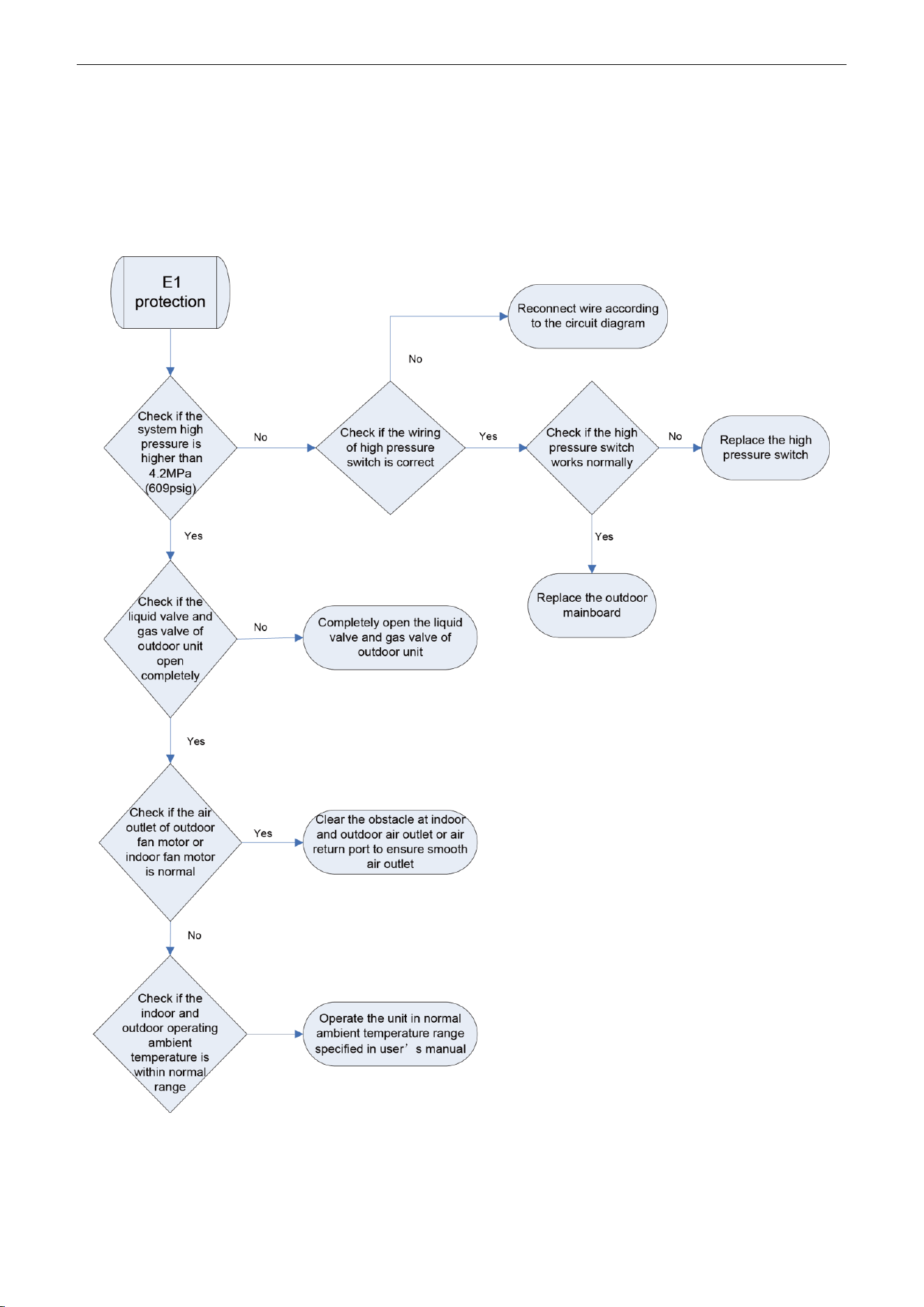
U-Match Series DC Inverter Service Manual
99
2 FLOW CHART OF TROUBLESHOOTING
2.1 Troubleshooting Flow Chart of Main Control Malfunction
E1 High Pressure Protection
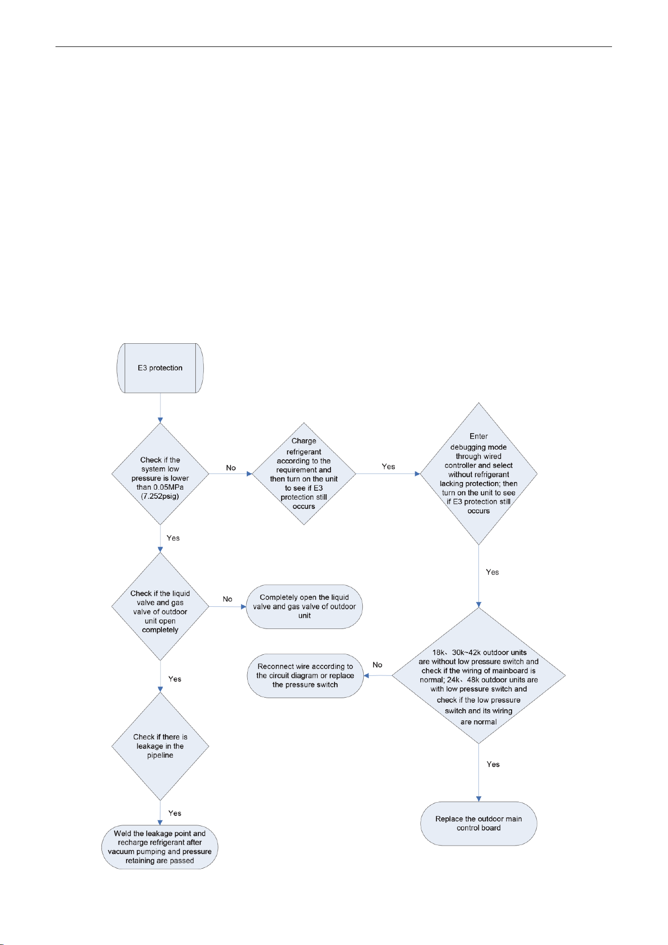
U-Match Series DC Inverter Service Manual
100
E2 Freeze Protection
Freeze protection is normal protection but not abnormal malfunction. If freeze protection occurs
frequently during operation, please check if the indoor filter is with filth blockage or if the indoor air outlet is
abnormal. The user is required to clean the filter, check the air outlet and air return pipe periodically to
ensure smooth air return and air outlet.
E3 stands for three statuses:
(1) Low pressure protection;
(2) Refrigerant lacking protection;
(3) Refrigerant recycling mode;
1) If enter refrigerant recycling mode through special operation, the displayed E3 is not an error
code. It will be eliminated when exiting refrigerant recycling mode.
2) If you do not want to have refrigerant lacking protection, you can enter the debugging mode
through wired controller and then cancel the refrigerant lacking protection mode.
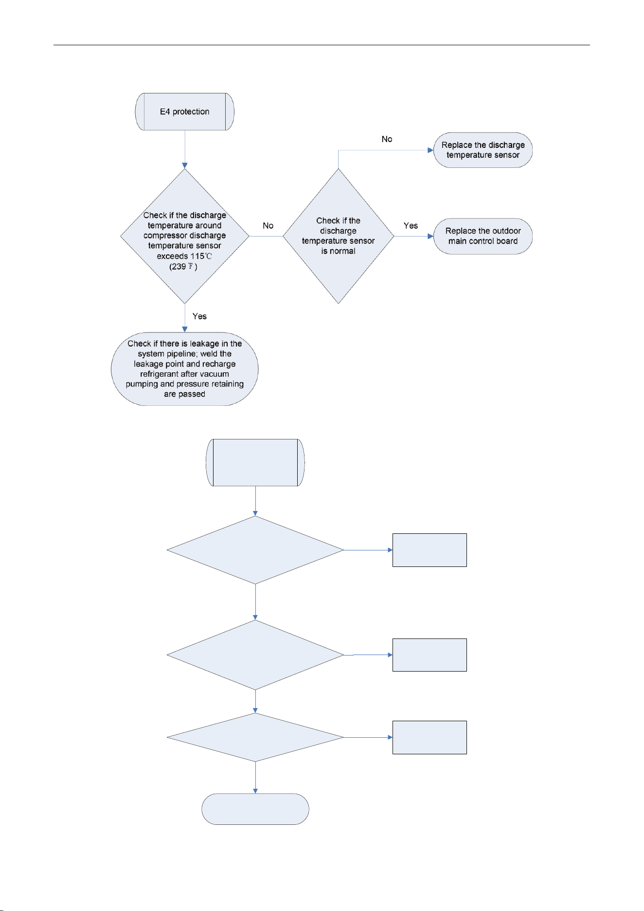
U-Match Series DC Inverter Service Manual
101
E4 Discharge Protection
E6 Communication Malfunction
Communication
malfunction
Check if the
communication wire between
indoor unit and outdoor unit is
connected well
Check if there is
open circuit in the communication
wire between indoor unit and
outdoor unit
Reconnect the
communication
wire
Replace the
communication
wire
Check if the
outdoor unit is energized
Energize the
outdoor unit
Replace the mainboard
Yes
Yes
No
No
No
Yes
U-Match Series DC Inverter Service Manual
102
E9 Full Water Protection
E9 protection
If the unit is
installed with
water pump
No
Yes
Replace the water pump
Short circuit the full water
protection interface on indoor
mainboard according to the circuit
diagram
Check if the
water pump
works normally
No
Replace the full water switch
or make sure the float of full
water switch works normally
Yes
F0 Malfunction of Indoor Ambient Temperature Sensor
Malfunction of
indoor ambient
temperature
sensor
Check if the
indoor ambient temperature
sensor on mainboard is inserted
on the needle
stand correctly
Disconnect
the temperature sensor and
measure if its resistance is
normal
Correctly insert the
temperature sensor
on the needle stand
Replace the
temperature sensor
Replace the indoor
mainboard
Yes
No
No
Yes
U-Match Series DC Inverter Service Manual
103
F1 Malfunction of Evaporator Temperature Sensor
Malfunction of
evaporator
temperature
sensor
Check if the evaporator
temperature sensor on
mainboard is inserted on the
needle stand correctly
Disconnect
the temperature sensor and
measure if its resistance is
normal
Correctly insert the
temperature
sensor on the
needle stand
Replace the
temperature
sensor
Replace the
indoor
mainboard
Yes
No
No
Yes
F2 Malfunction of Condenser Temperature Sensor
Malfunction of
condenser
temperature
sensor
Check if the condenser
temperature sensor on
mainboard is inserted on the
needle stand correctly
Disconnect
the temperature sensor and
measure if its resistance is
normal
Correctly insert the
temperature sensor
on the needle stand
Replace the
temperature sensor
Replace the
outdoor
mainboard
Yes
No
No
Yes
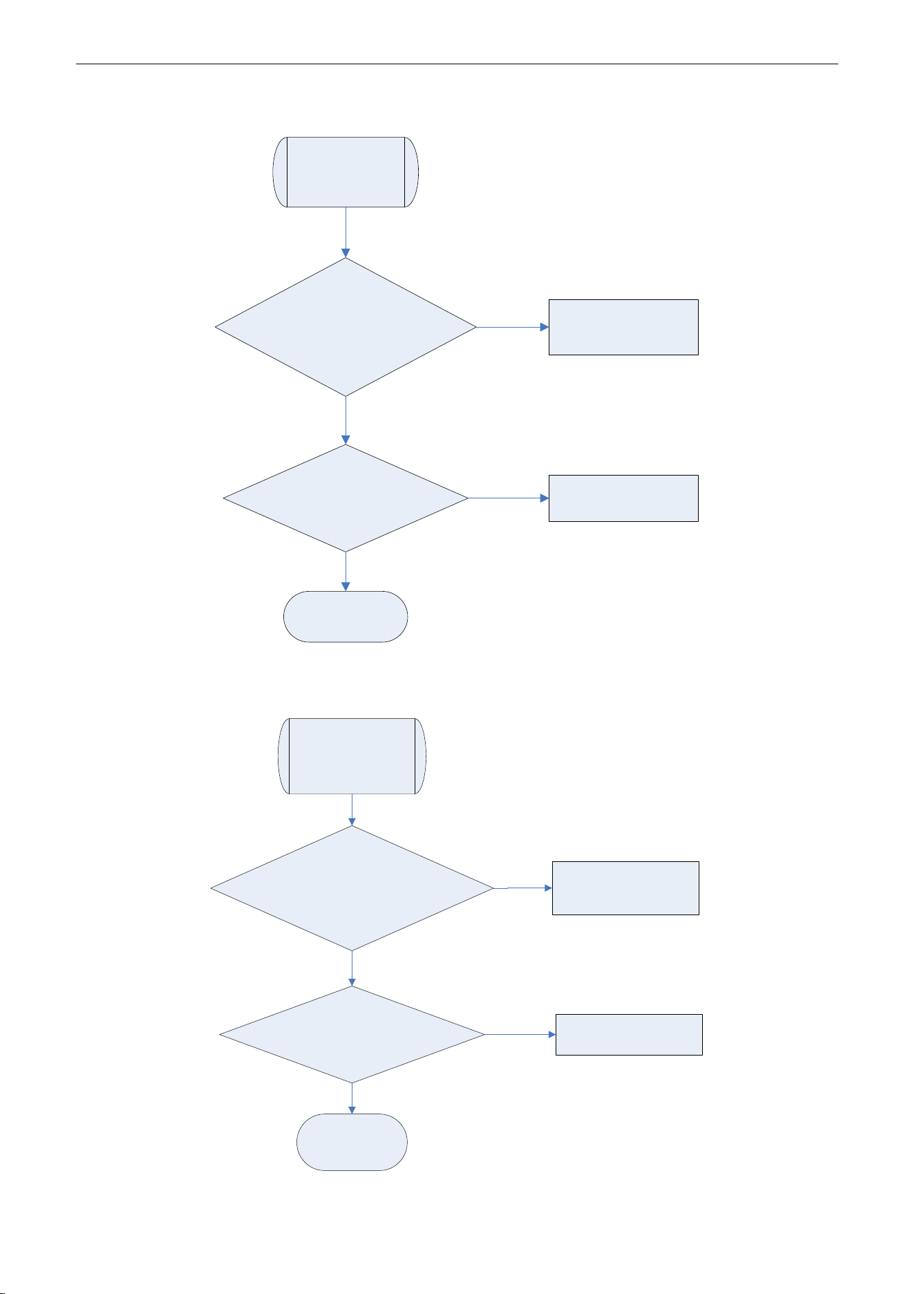
U-Match Series DC Inverter Service Manual
104
F3 Malfunction of Outdoor Ambient Temperature Sensor
Malfunction of
outdoor ambient
temperature
sensor
Check
if the outdoor ambient
temperature sensor on mainboard
is inserted on the needle stand
correctly
Disconnect
the temperature sensor and
measure if its resistance is
normal
Correctly insert the
temperature sensor on
the needle stand
Replace the
temperature sensor
Replace the
outdoor
mainboard
Yes
No
No
Yes
F4 Malfunction of Discharge Temperature Sensor
Malfunction of
discharge
temperature
sensor
Check if the
discharge temperature sensor on
mainboard is inserted on the
needle stand correctly
Disconnect
the temperature sensor and
measure if its resistance is
normal
Correctly insert the
temperature sensor
on the needle stand
Replace the
temperature sensor
Replace the
outdoor
mainboard
Yes
No
No
Yes
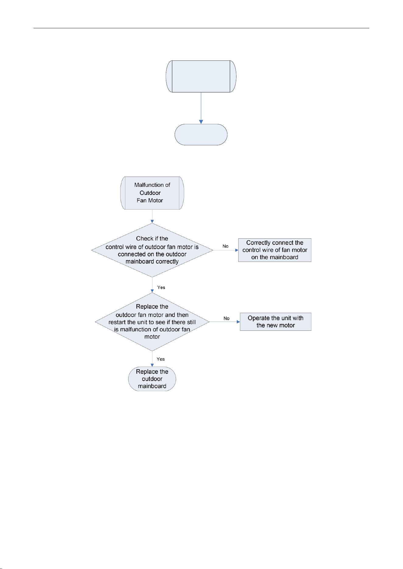
U-Match Series DC Inverter Service Manual
105
F5 Malfunction of Wired Controller Temperature Sensor
Malfunction of
wired controller
temperature
sensor
Replace the
wired controller
H6 Malfunction of Outdoor Fan Motor
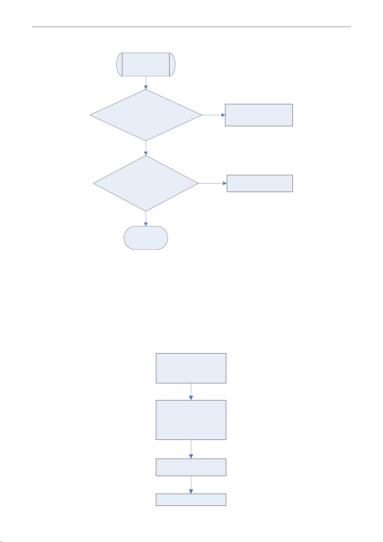
U-Match Series DC Inverter Service Manual
106
E8 Malfunction of Indoor Fan Motor
Malfunction of
indoor fan motor
Check if the
control wire of indoor fan motor is
connected on the outdoor
mainboard correctly
Replace
the indoor fan motor and then
restart the unit to see if there still
is malfunction of indoor
fan motor
Correctly connect the
control wire of fan motor
on the mainboard
Operate the unit with
the new motor
Replace the
indoor
mainboard
Yes
No
No
Yes
2.2 Troubleshooting Flow Chart of Drive Malfunction
Note: For Outdoor Unit Drive (Inverter) by Single-phase Motor
P0 Drive module reset
P7 IPM or PFC temperature sensor error
PA AC current protection (input side)
PC Current sense circuit error
HC PFC protection (48k only)
P0、P7、PA、HC or
PC is displayed on
the wired controller
P0、P7、PA、Hc or
PC is displayedin the
mainboard 88
Indicating Lamp
Replace the
mainboard
Work Normally
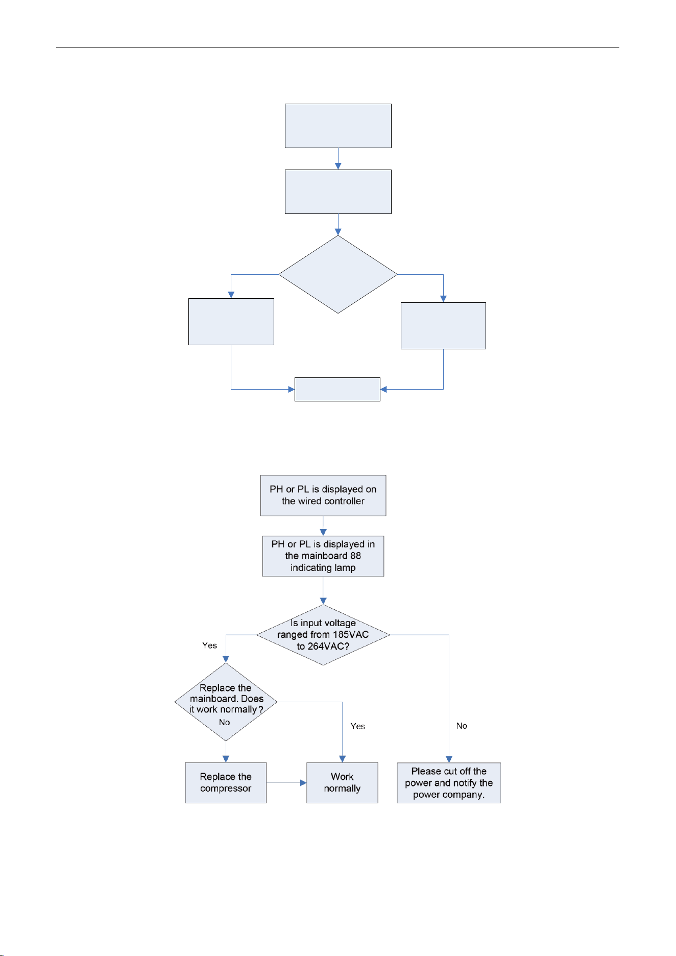
U-Match Series DC Inverter Service Manual
107
P8 IPM or PFC over-temperature protection
P8 is displayed on
the wired controller
P8 is displayed in the
mainboard 88
Indicating lamp
Is the
IPM or PFC module
of mainboard
tightened?
No
Work normally
Replace the
mainboard
Yes
Tighten the IPM
or PFC module
PH DC busbar over-voltage protection
PL DC busbar under-voltage protection
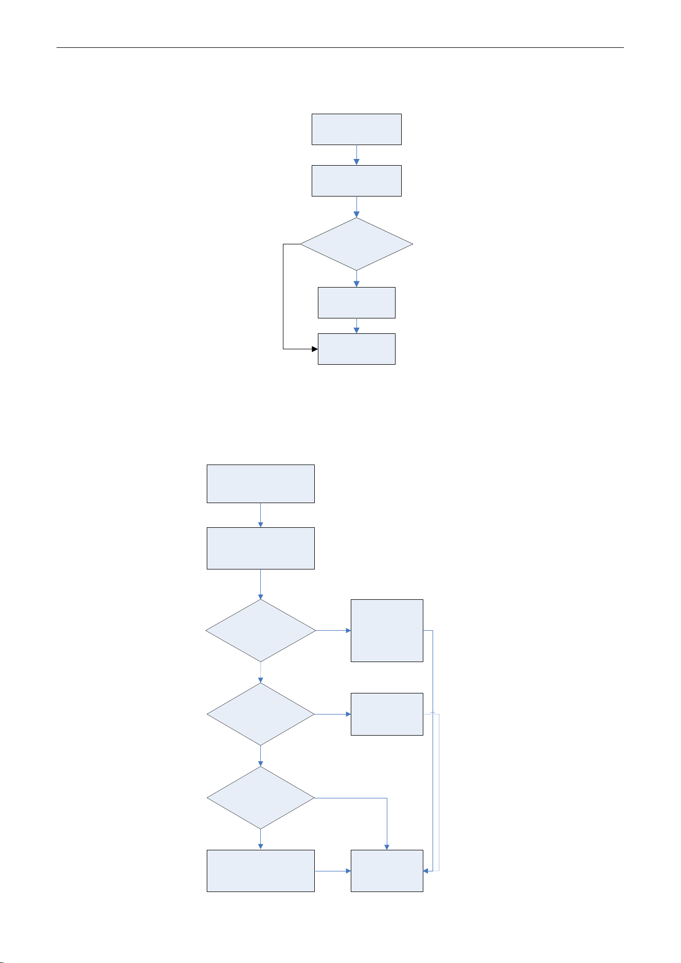
U-Match Series DC Inverter Service Manual
108
P6 Drive-to-main-control communication error
Lc Compressor Startup Failure
Lc is displayed on
the wired controller
Lc is displayed in
the mainboard 88
indicating lamp
Replace the
mainboard. Does it
work normally?
Replace the
compressor
Work normally
Yes
No
P5 Compressor current protection
H7 Compressor motor desynchronizing
H5 IPM protection
Ld Phase loss
P5, H7, H5 or Ld is displayed
in the mainboard 88
indicating lamp
Is the compressor
phase sequence right?
Yes
Replace the mainboard.
Does it work normally?
No
Replace the compressor Work normally
Yes
adjust the
compressor
phase sequence
Is the compressor wire
terminals tightened?
Tighten the
compressor wire
terminals
Yes
No
No
P5, H7, H5 or Ld is displayed
on the wired controller
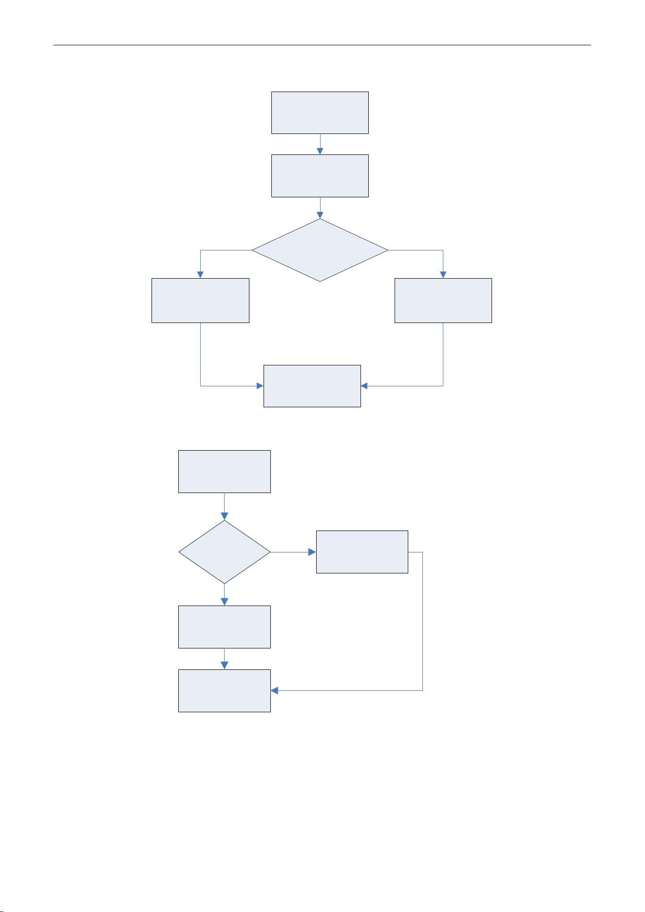
U-Match Series DC Inverter Service Manual
109
PU Charging circuit error
PU is displayed on
the wired controller
PU is displayed in
the mainboard 88
indicating lamp
Is the PFC wire
tightened or is the
sequence right?
Tighten the PFC
wire or adjust the
sequence
Replace the
mainboard
Yes
No
Work normally
ee driving board chip error
Yes
Yes
ee is displayed
on the wired
controller
Is the
jumper
loose?
Work Normally
Tighten the
jumper
Replace the
mainboard
No
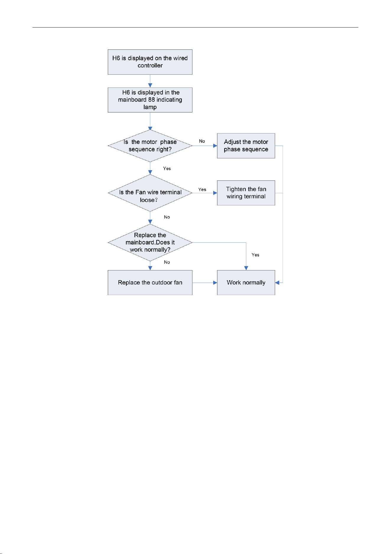
U-Match Series DC Inverter Service Manual
110
H6 DC fan error
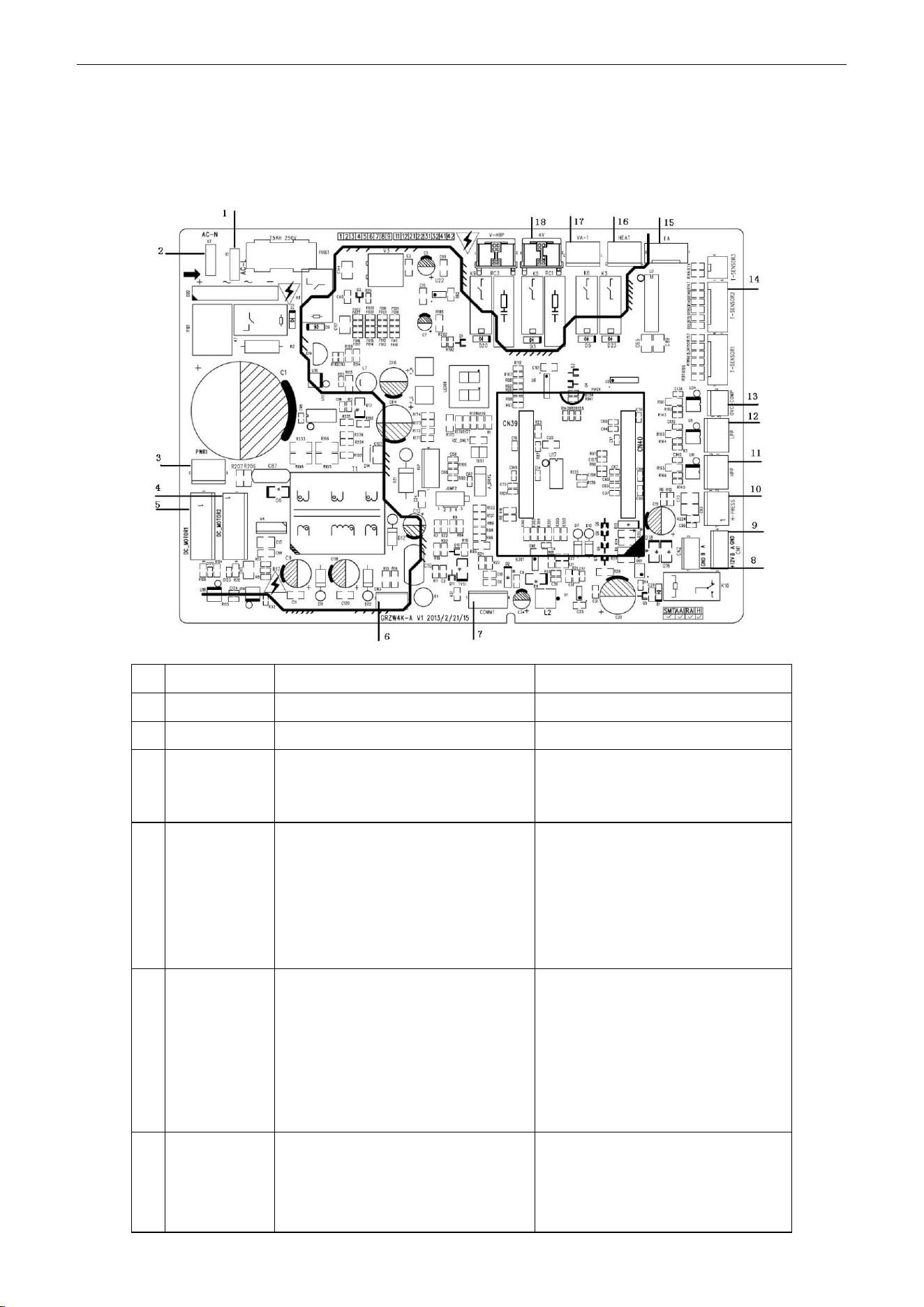
U-Match Series DC Inverter Service Manual
111
2.3 Interface
UMAT18HP230V1AO/UMAT24HP230V1AO/ UMAT30HP230V1AO/ UMAT36HP230V1AO /
UMAT42HP230V1AO /UMAT48HP230V1AO Main Control Board
NO.
SILK-SCREEN
INTERFACE
INTERFACE INSTRUCTION
1
AC-L
Live wire input
Live wire input
2
AC-N
Neutral wire input
Neutral wire input
3
PWR 1
Control power output[1- DC bus
voltage, 3- GND]
Power supply interface to the drive
1-pin: DC bus voltage
3-pin: DC bus GND
4
DC_MOTOR2
DC fan motor2
1-pin: Power supply of fan motor
3-pin: Fan GND
4-pin: +15V
5-pin: Signal control
6-pin: NC
Interface of DC fan motor
1-pin: DC bus voltage
2-pin: Suspended
3-pin: DC bus GND
4-pin: +15V
5-pin: Control signal input
6-pin: Not connected
5
DC_MOTOR1
DC fan motor1
1-pin: Power supply of fan motor
3-pin: Fan GND
4-pin: +15V
5-pin: Signal control
6-pin: Signal Feedback
Interface of DC fan motor
1-pin: DC bus voltage
2-pin: Suspended
3-pin: DC bus GND
4-pin: +15V
5-pin: Control signal input
6-pin: DC fan motor feedback
6
CN3
Control power output[1-GND
、
2-18V
、
3-15V]
Power supply interface to the drive
1-pin: GND
2-pin: +18V
3-pin: +15V
U-Match Series DC Inverter Service Manual
112
7
COMM1
Communication line [1-3.3V
、
2-TX
、
3-RX
、
4-GND]
Communication needle stand of
main control drive
1-pin: +3.3V
2-pin: TXD
3-pin: RXD
4-pin: GND
8
CN2
Communication line with1-pin
GND, 2-pin B and 3-pinA
)
Communication needle stand with
indoor unit
1-pin: GND
2-pin: B
3-pin: A
9
CN1
Communication line with 1-pin plus
12V, 2-pin B, 3-pin A and 4-pin
GND
Communication interface
(reserved):
1-pin: +12V
2-pin: B
3-pin: A
4-pin: GND
10
H-PRESS
High pressure switch for fan speed
adjustment
Pressure protection switch for fan
speed adjustment
11
HPP
High pressure switch for system
protection (obligate
)
Interface of high pressure
protection
12
LPP
Low pressure switch for system
protection (obligate
)
Interface of low pressure
protection
13
OVC-COMP
Compressor overload protection
Interface of compressor overload
protection
14
T-SENSOR2
1&2 pin: Tube sensor
3&4 pin: Ambient temperature
5&6 pin: Air discharge
1&2 pin: Case temperature sensor
3&4 pin: Ambient temperature
sensor
5&6 pin: Discharge temperature
sensor
15
FA
Electronic expansion valve line
1 to 4-pin: Drive impulse
output;5-pin: +12V;
Interface of electronic expansion
valve:
1 to 4-pin: Drive impulse output;
5-pin: +12V;
16
HEAT
Compressor electrical heater
Compressor electric heating belt
17
VA-1
Chassis electrical heater
Chassis electric heating belt
18
4V
4-way valve
4-way valve
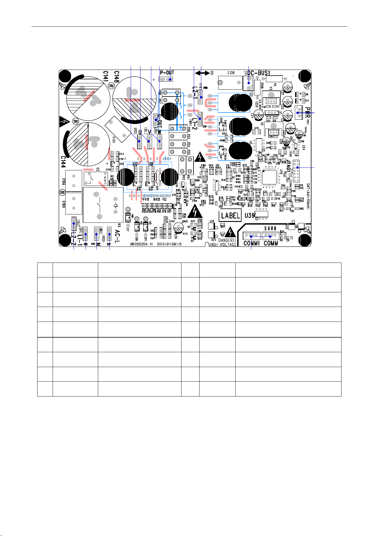
U-Match Series DC Inverter Service Manual
113
UMAT18HP230V1AO/UMAT24HP230V1AO/UMAT30HP230V1AO/
UMAT36HP230V1AOGUHD42ND3FO
(1) Driving Board
2 3 41 5
6
7
8910131415 1112
No.
Printing
Interface
No.
Printing
Interface
1
L2_2
PFC induction wire (blue)
2
L1_1
PFC induction wire (brown)
3
N
Neutral wire input (white)
4
AC-L
Live wire input (red)
5
COMM/COMM1
Communication interface
6
JTAG1
(Reserved)
7
PWR
Control power input
8
DC-BUS1
Bus electric discharging interface (for
testing)
9
L2-1
PFC induction wire (yellow)
10
L1-2
PFC induction wire (white)
11
P-OUT
(Reserved)
12
G-OUT
(Reserved)
13
W
Compressor Phase W
14
V
Compressor Phase V
15
U
Compressor Phase U
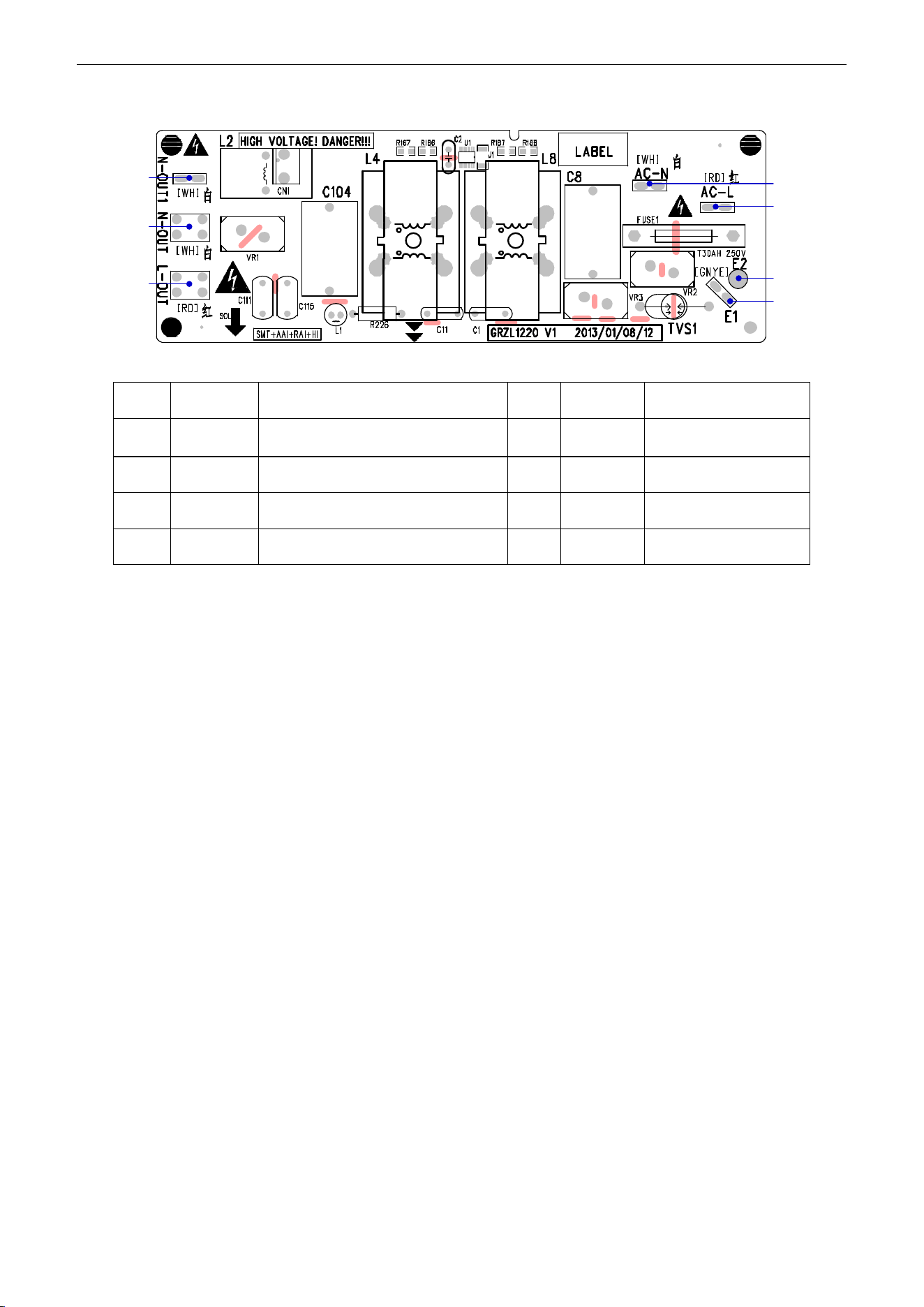
U-Match Series DC Inverter Service Manual
114
(2)
Filtering Board
1
2
3
5
4
6
7
No.
Printing
Interface
No.
Printing
Interface
1
N-OUT1
Neutral wire output 1 (white) (only for
18k)
2
N-OUT
Neutral wire output
(white)
3
L-OUT
Live wire output (red)
4
E1
Grounding wire
5
E2
(Reserved)
6
AC-L
Live wire input (red)
7
AC-N
Neutral wire input (white)

U-Match Series DC Inverter Service Manual
115
UMAT48HP230V1AO
(1) Drive Board:
11
1
8
2
3
4
5
6
7
9
10
121314
No.
Printing
Interface
No.
Printing
Interface
1
AC-L
Live wire input (red)
2
L1-1
PFC induction wire (brown)
3
N
Neutral wire input (white)
4
L2-2
PFC induction wire (blue)
5
L2-1
PFC induction wire (yellow)
6
L1-2
PFC induction wire (white)
7
PWR
Control power input
8
JTAG1
(Reserved)
9
COMM
Communication interface
10
DC-BUS1
DC bus electric discharging needle
stand (for testing)
11
DC-BUS
DC bus interface (connect to
filtering board)
12
U
Compressor Phase U
13
V
Compressor Phase V
14
W
Compressor Phase W
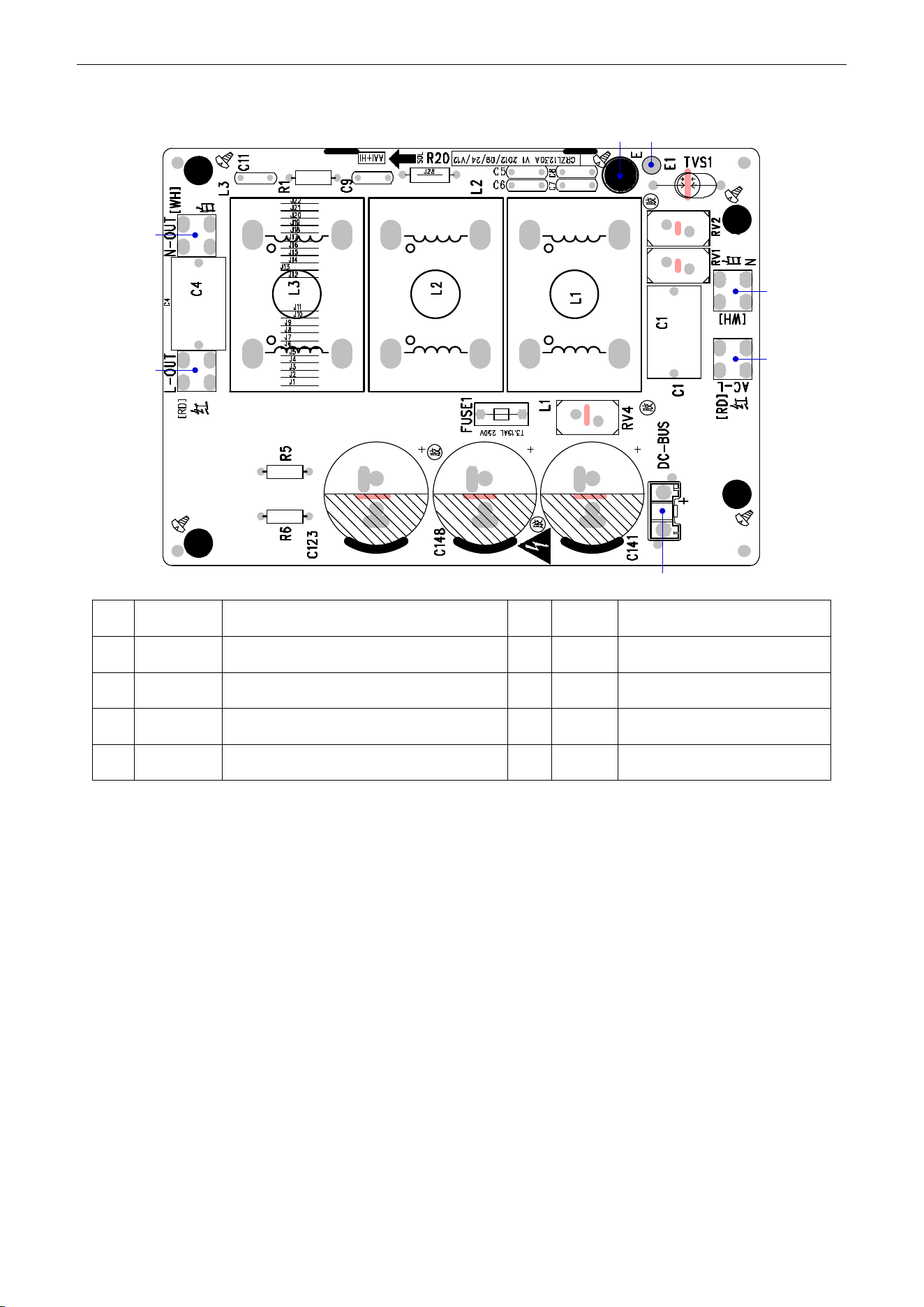
U-Match Series DC Inverter Service Manual
116
(2) Filtering Board:
3
4
5
67
1
2
No.
Printing
Interface
No.
Printing
Interface
1
N-OUT
Neutral wire output (white)
2
L-OUT
Live wire output (red)
3
DC-BUS
DC bus interface (connect to drive board)
4
AC-L
Live wire input (red)
5
N
Neutral wire input (white)
6
E1
(Reserved)
7
E
Grounding wire (screw hole)
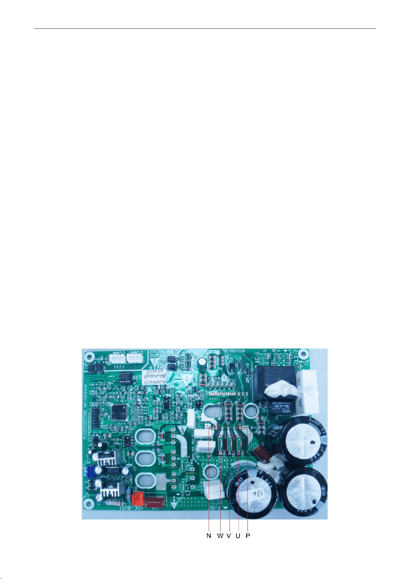
U-Match Series DC Inverter Service Manual
117
2.4 IPM, PFC Testing Method
2.4.1 Method of Testing IPM Module
(1) Preparation before test: prepare a universal meter and turn to its diode option, and then remove
the wires U, V, W of the compressor after it is powered off for one minute.
(2) Testing Steps
Step 1: put the black probe on the place P and the red one on the wiring terminal U, V, W respectively
as shown in the following figure to measure the voltage between UP, VP and WP.
Step 2: put the red probe on the place N and the black one on the wiring terminal U, V, W respectively
as shown in the following figure to measure the voltage between NU, NV and NW.
(3) If the measured voltages between UP, VP, WP, NU, NV, NV are all among 0.3V-0.7V, then it
indicates the IPM module is normal; If any measured valve is 0, it indicates the IPM is damaged.
2.4.2
Method of Testing PFC Module Short Circuit (only for UMAT48HP230V1AO):
(1) Preparation before test: prepare a universal meter and turn to its diode option, and then remove
the wires L1-2, L2-1 after it is powered off for one minute.
(2) Testing Steps
Step 1: put the black probe on the place P and the red one on the wiring terminal L1-2,
L2-1respectively as shown in the following figure to measure the voltage between L1-2P and.L2-1 P.
Step 2: put the red probe on the place N and the black one on the wiring terminal L1-2,
L2-1respectively as shown in the following figure to measure the voltage between N L1-2 and NL2-1.
(3) If the measured voltages between L1-2P ,L2-1 P, N L1-2 , NL2-1 are all among 0.3V-0.7V, then it
indicates the PFC module is normal; If any measured valve is 0, it indicates the PFC is damaged.
UMAT18HP230V1AO/UMAT24HP230V1AO/ UMAT30HP230V1AO /UMAT36HP230V1AO
UMAT42HP230V1AO
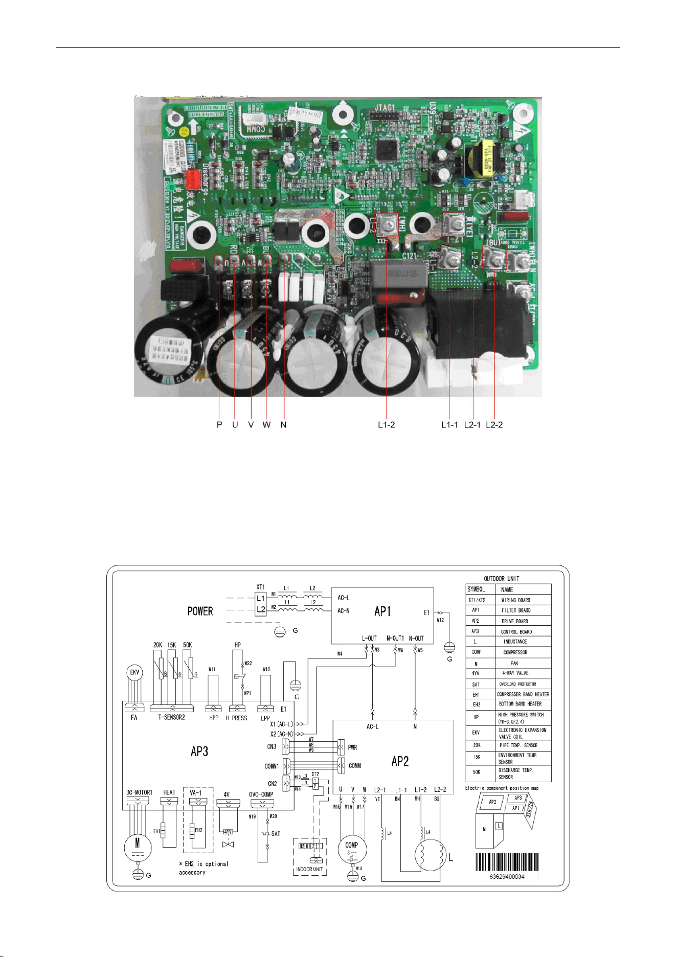
U-Match Series DC Inverter Service Manual
118
UMAT48HP230V1AO
3 WIRING DIADRAM
3.1 Outdoor unit
The actual wiring should always refer to the wiring diagram of the unit.
Model:
UMAT18HP230V1AO
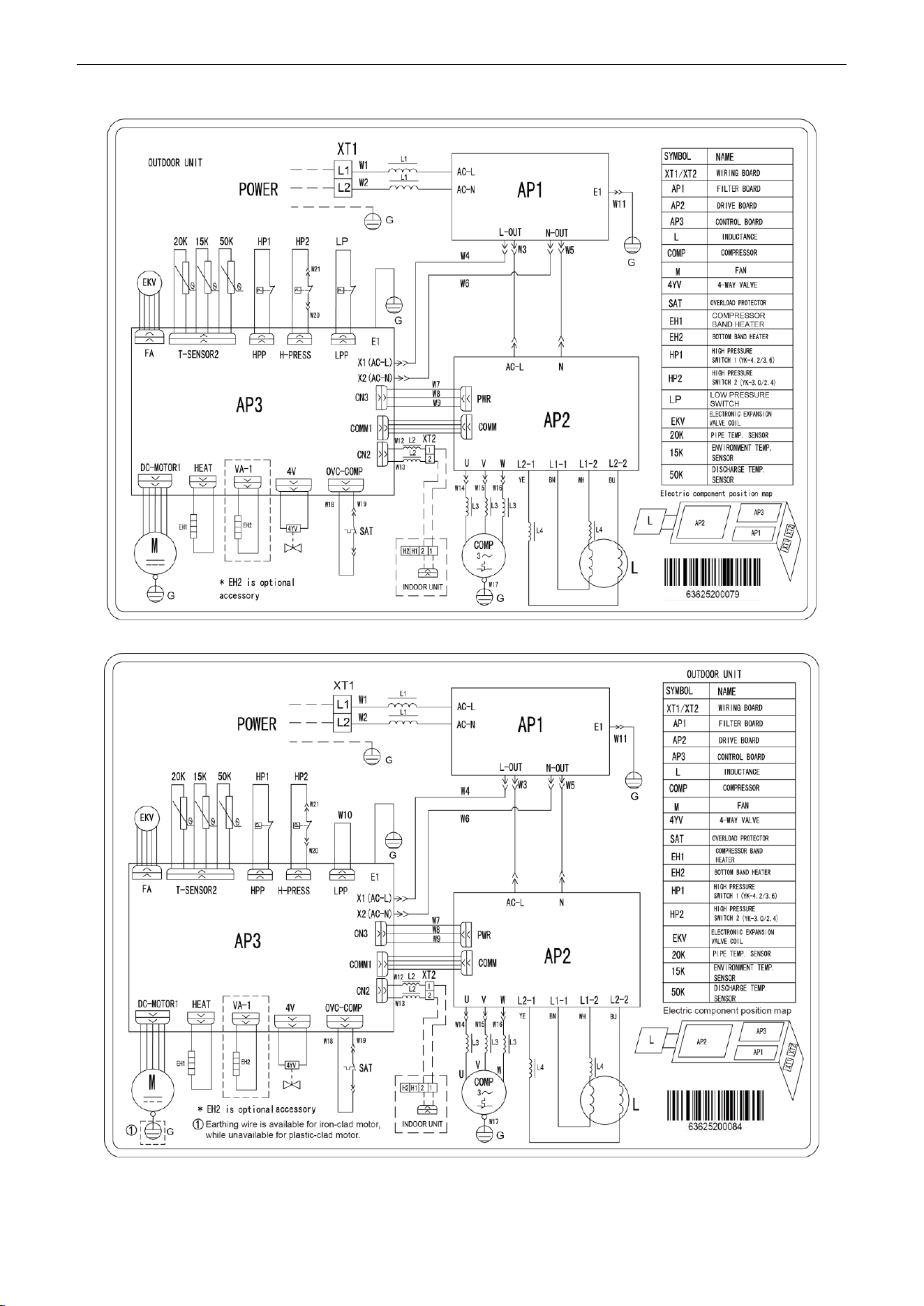
U-Match Series DC Inverter Service Manual
119
Model: UMAT24HP230V1AO
Model: UMAT30HP230V1AO
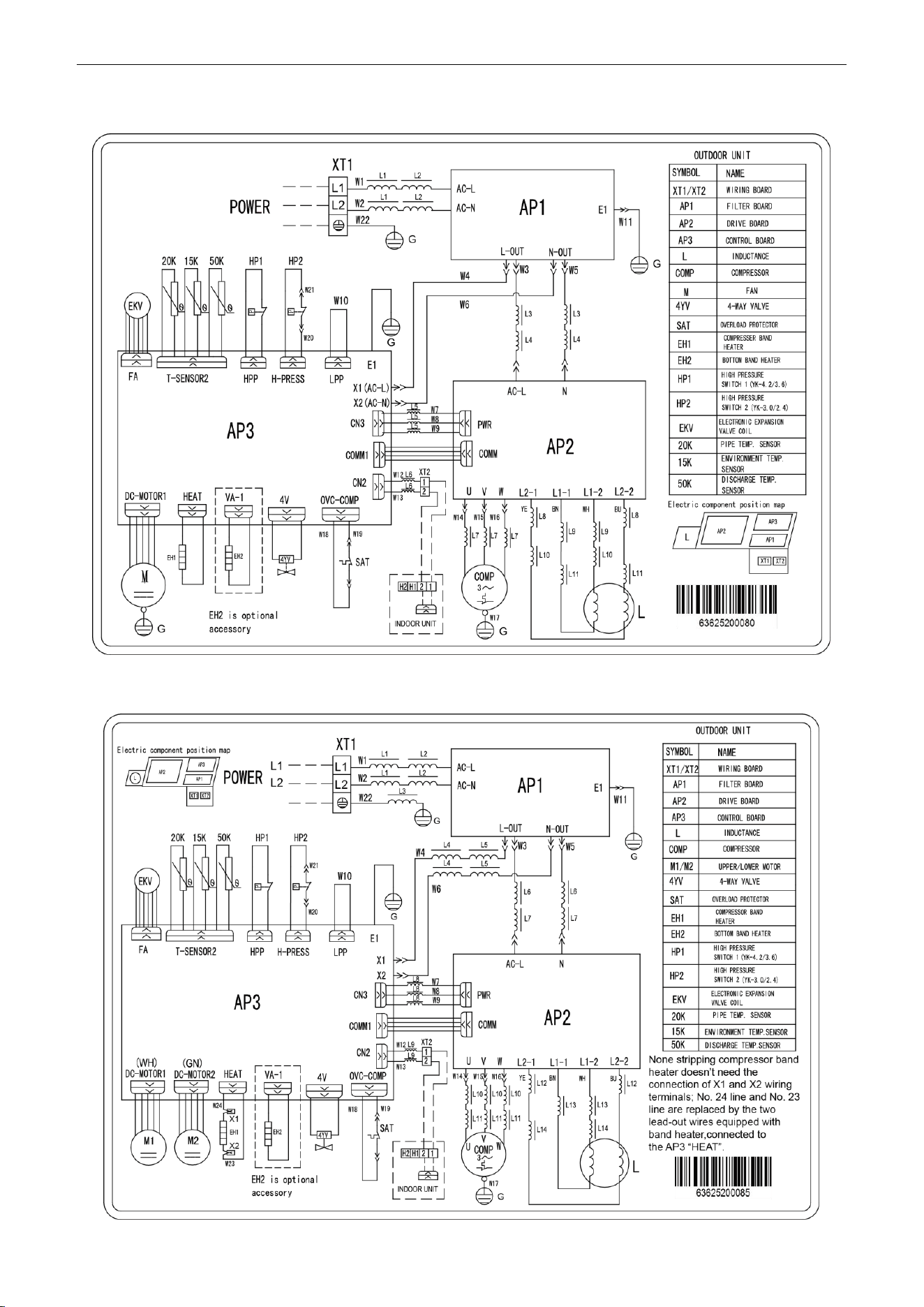
U-Match Series DC Inverter Service Manual
120
Model: UMAT36HP230V1AO
Model: UMAT42HP230V1AO
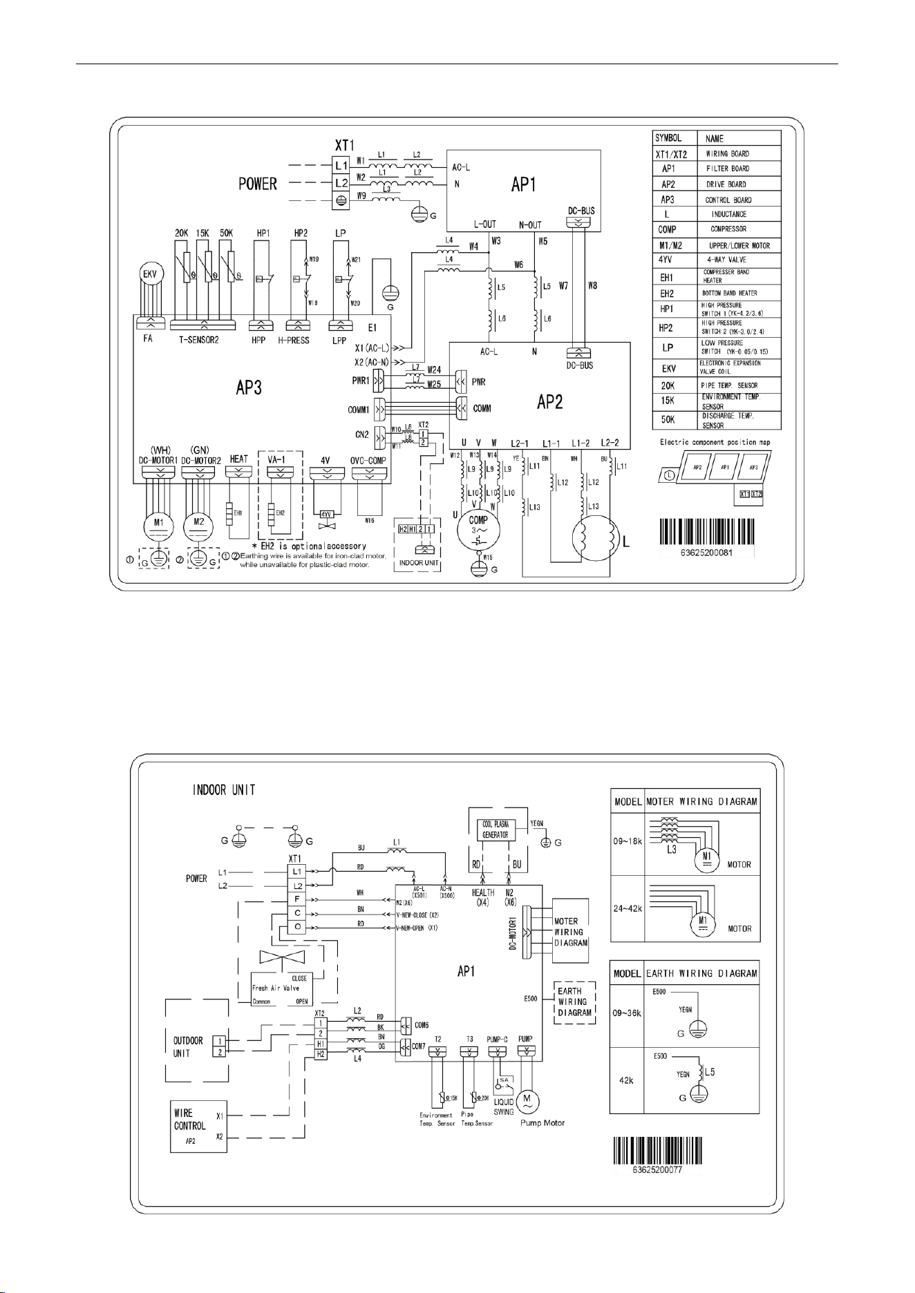
U-Match Series DC Inverter Service Manual
121
Model: UMAT48HP230V1AO
3.2 Indoor unit
The actual wiring should always refer to the wiring diagram of the unit.
3.2.1 Duct Type
Model: UMAT18HP230V1AD/UMAT24HP230V1AD/UMAT30HP230V1AD/UMAT36HP230V1AD/
UMAT42HP230V1AD
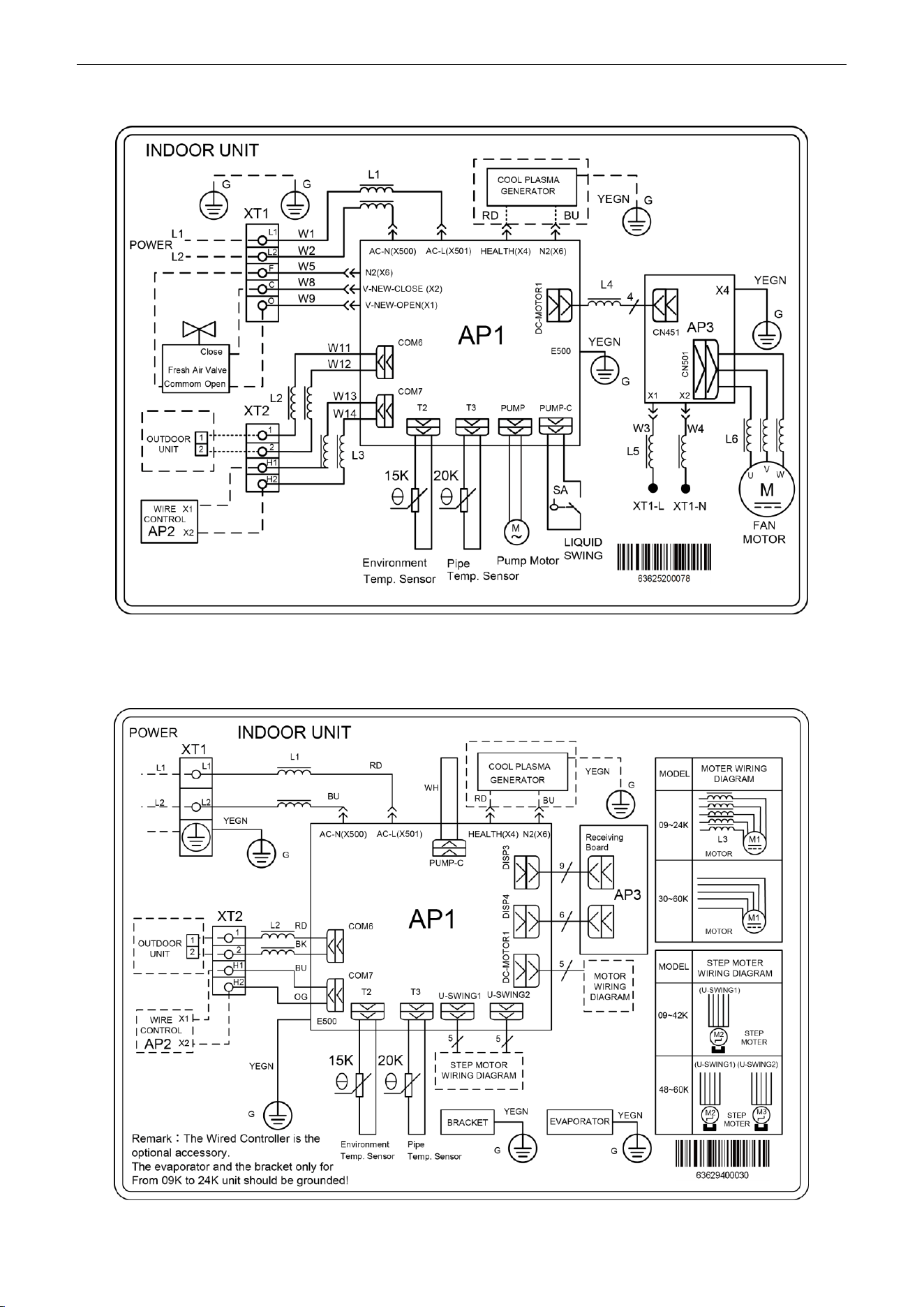
U-Match Series DC Inverter Service Manual
122
Model: UMAT48HP230V1AD
3.2.2 Floor Ceiling Type
Model: UMAT18HP230V1AF/UMAT24HP230V1AF/UMAT30HP230V1AF/UMAT36HP230V1AF/
UMAT42HP230V1AF/UMAT48HP230V1AF
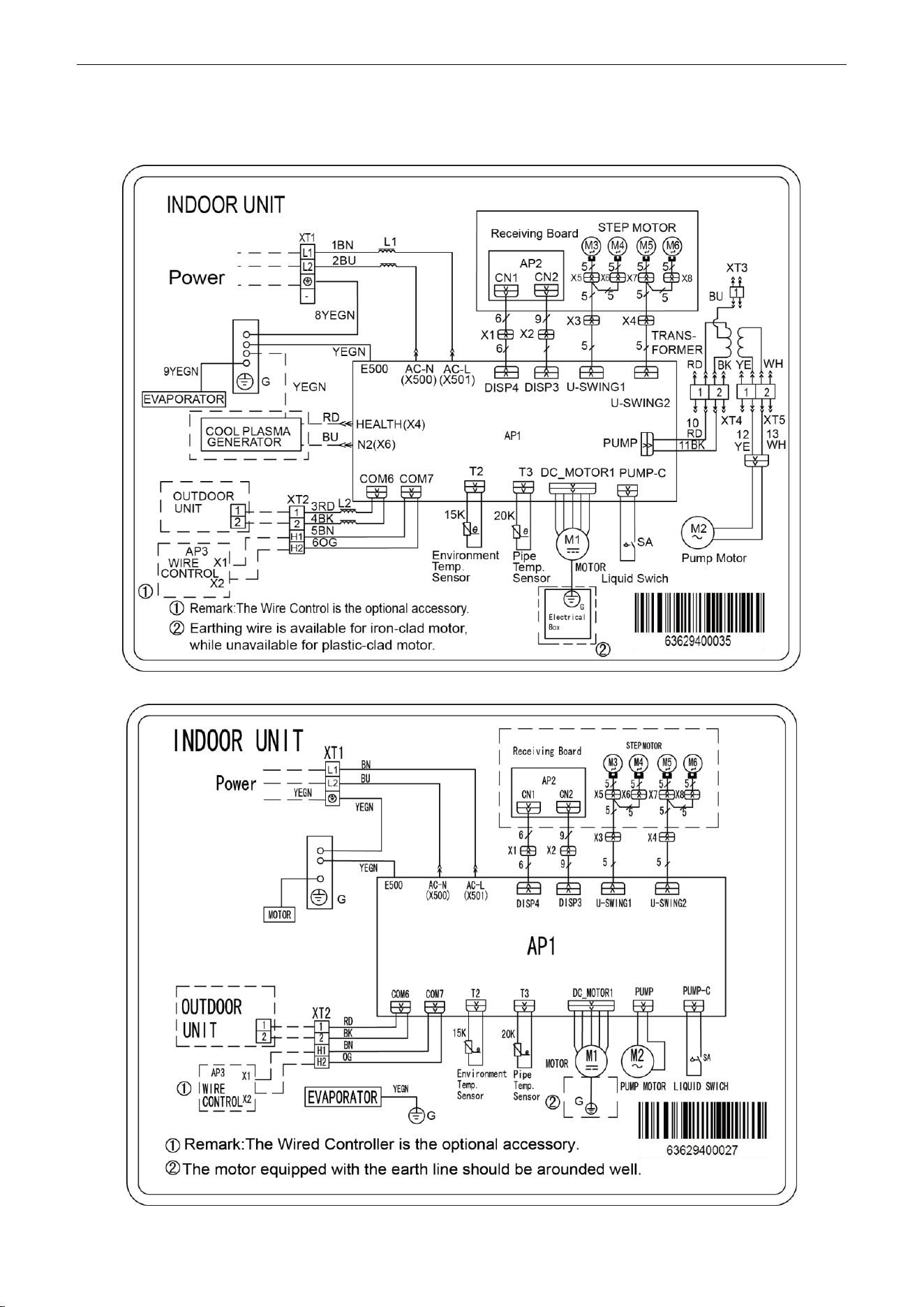
U-Match Series DC Inverter Service Manual
123
3.2.3 Cassette Type
Model: UMAT18HP230V1AC
Model: UMAT24HP230V1AC/UMAT30HP230V1AC/UMAT36HP230V1AC/UMAT42HP230V1AC
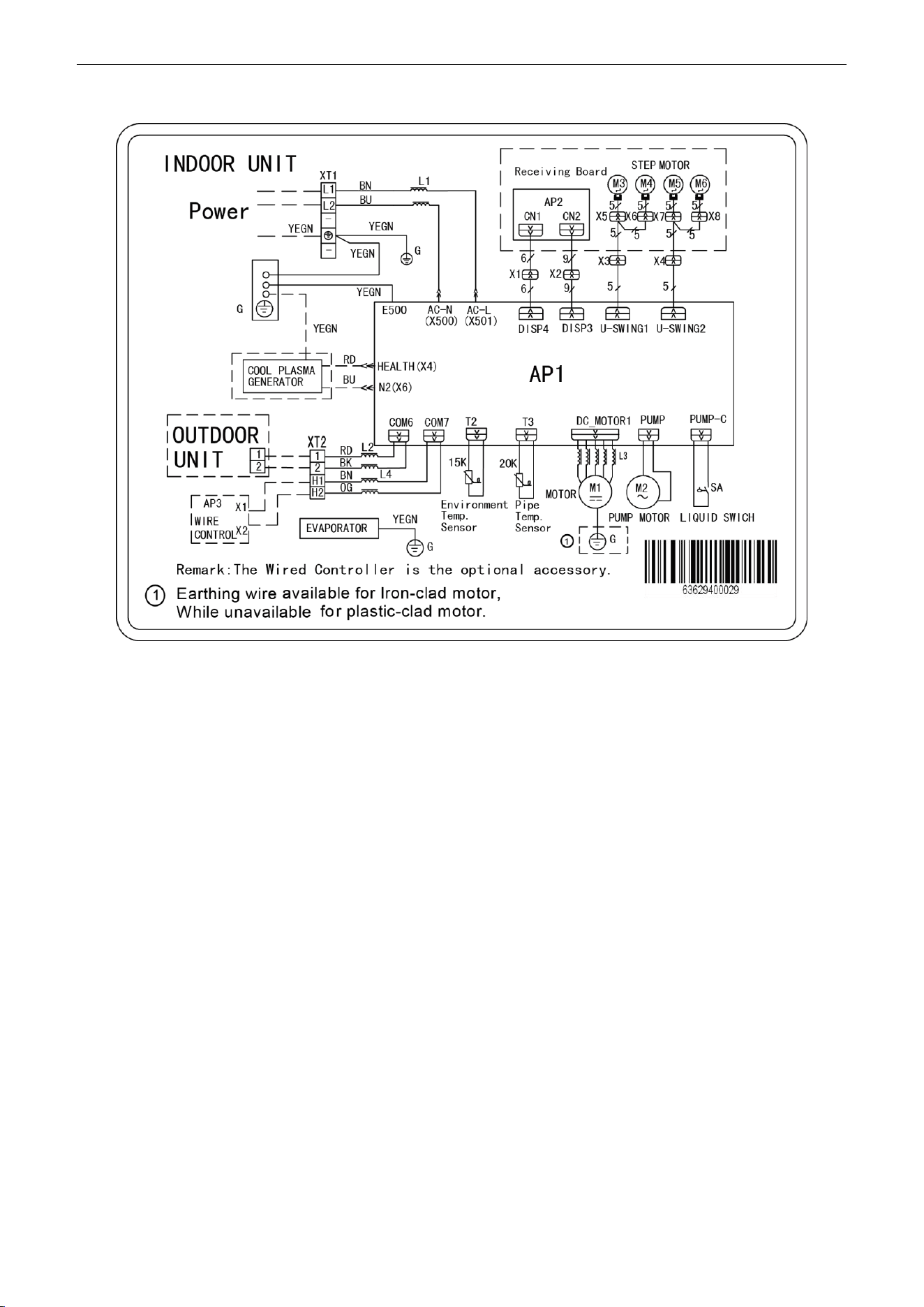
U-Match Series DC Inverter Service Manual
124
Model: UMAT48HP230V1AC
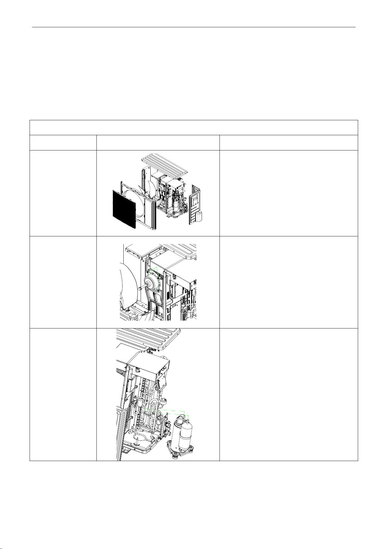
U-Match Series DC Inverter Service Manual
125
4 DISASSEMBLY AND ASSEMBLY
PROCEDURE OF MAIN PARTS
4.1 Outdoor Unit
18k:
Remark: Before disassembly and assembly, make sure that the unit has been cut off from the power supply.
Step
Illustration
Handling Instruction
1. Remove external
casing
1. Remove the top cover and handle;
2. Remove the grille, outer case and right side
plate.
2. Remove motor
1. Remove the blade nut and then remove the
blade;
2. Remove the motor from motor support.
3. Remove compressor
1. Discharge the refrigerant inside the pipeline and
recycle the refrigerant during discharging;
2. Unsolder the 4-way valve assy from
compressor;
3. Remove the nut fixing compressor;
4. Take away the compressor from chassis.
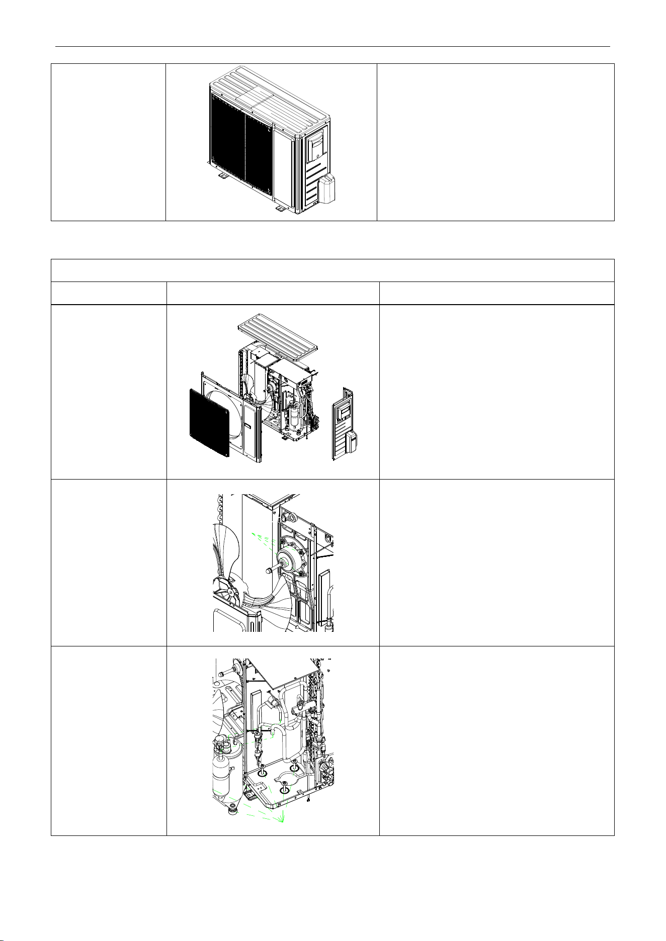
U-Match Series DC Inverter Service Manual
126
4. Assemble unit
Assemble the unit in the reverse procedures of
disassembly.
24k/30k:
Remark: Before disassembly and assembly, make sure that the unit has been cut off from the power supply.
Step
Illustration
Handling Instruction
1. Remove external
casing
1. Remove the top cover and handle;
2. Remove the grille, outer case, front side plate
and right side plate.
2. Remove motor
1. Remove the blade nut and then remove the
blade;
2. Remove the motor from motor support.
3. Remove compressor
1. Discharge the refrigerant inside the pipeline
and recycle the refrigerant during discharging;
2. Unsolder the 4-way valve assy from
compressor;
3. Remove the nut fixing compressor;
4. Take away the compressor from chassis.
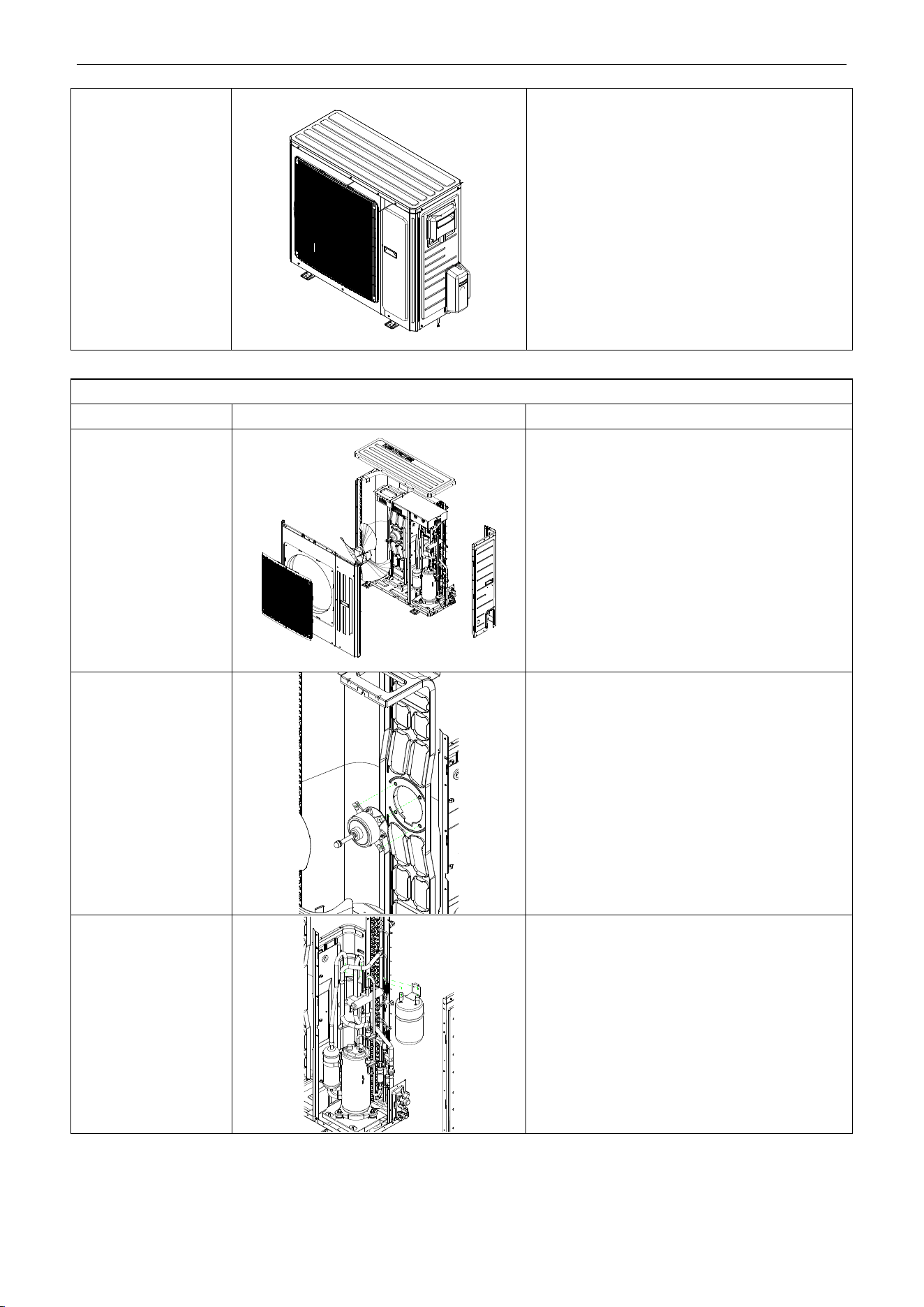
U-Match Series DC Inverter Service Manual
127
4. Assemble unit
Assemble the unit in the reverse procedures of
disassembly.
36k:
Remark: Before disassembly and assembly, make sure that the unit has been cut off from the power supply.
Step
Illustration
Handling Instruction
1. Remove external
casing
1. Remove the top cover and handle;
2. Remove the grille, outer case and right side
plate.
2. Remove motor
1. Remove the blade nut and then remove the
blade;
2. Remove the motor from motor support.
3. Remove gas liquid
separator
1. Discharge the refrigerant inside the pipeline and
recycle the refrigerant during discharging;
2. Unsolder the 4-way valve assy from gas liquid
separator;
3. Remove the gas liquid separator.
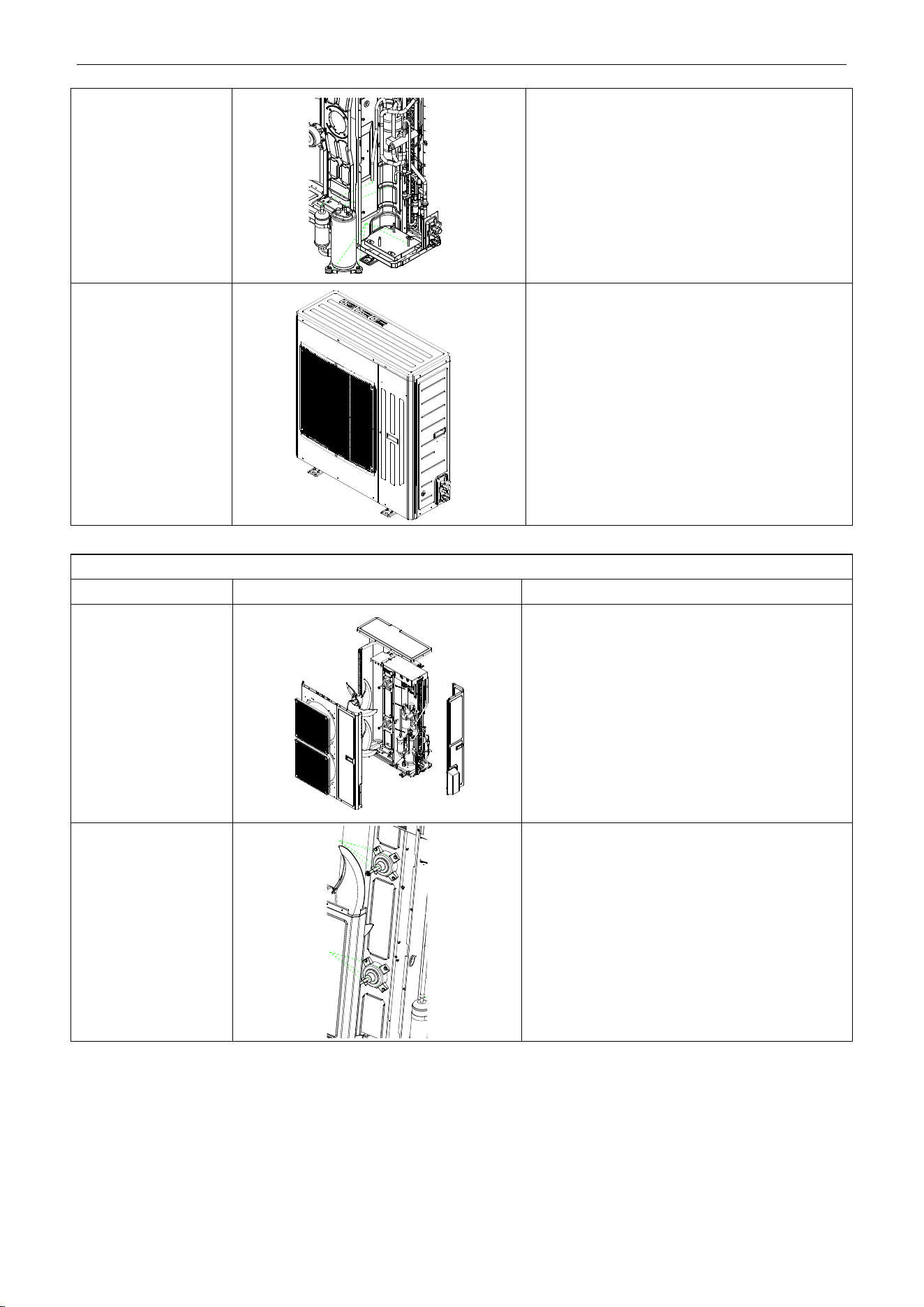
U-Match Series DC Inverter Service Manual
128
4. Remove compressor
1. Discharge the refrigerant inside the pipeline and
recycle the refrigerant during discharging;
2. Unsolder the 4-way valve assy from
compressor;
3. Remove the nut fixing compressor;
4. Take away the compressor from chassis.
5. Assemble unit
Assemble the unit in the reverse procedures of
disassembly.
42k/48k:
Remark: Before disassembly and assembly, make sure that the unit has been cut off from the power supply.
Step
Illustration
Handling Instruction
1. Remove external
casing
1. Remove the top cover and handle;
2. Remove the grille, outer case and right side
plate.
2. Remove motor
1. Remove the blade nut and then remove the
blade;
2. Remove the motor from motor support.
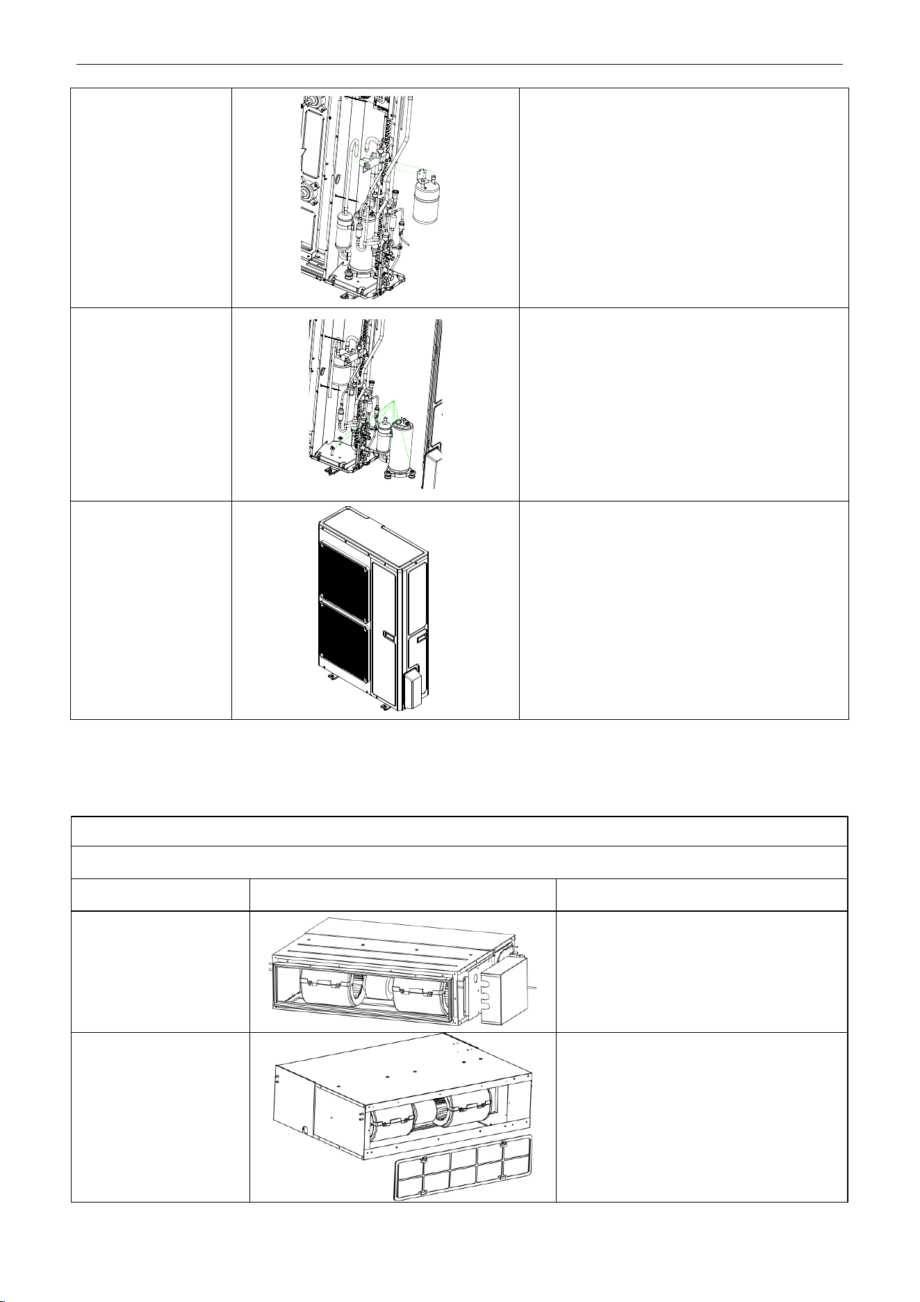
U-Match Series DC Inverter Service Manual
129
3. Remove gas liquid
separator.
1. Discharge the refrigerant inside the pipeline and
recycle the refrigerant during discharging;
2. Unsolder the 4-way valve assy from gas liquid
separator;
3. Remove the gas liquid separator.
4. Remove compressor
1. Discharge the refrigerant inside the pipeline and
recycle the refrigerant during discharging;
2. Unsolder the 4-way valve assy from
compressor;
3. Remove the nut fixing compressor;
4. Take away the compressor from chassis.
5. Assemble unit
Assemble the unit in the reverse procedures of
disassembly.
4.2 Indoor Unit
4.2.1 Duct type
Removal and Assembly of Fan Motor
Remarks: Before removing the fan, make sure to cut off the power firstly.
Step
Illustration
Handling Instruction
1. Unplug the motor
cables
Cut off the power supply of indoor unit. Use
screwdriver to remove the electric box cover
and unplug the motor cables in electric box.
2. Remove the filter
sub-assembly and air inlet
cover board
Remove the filter sub-assembly from the air
inlet frame and use screwdriver to remove
the air inlet cover board.
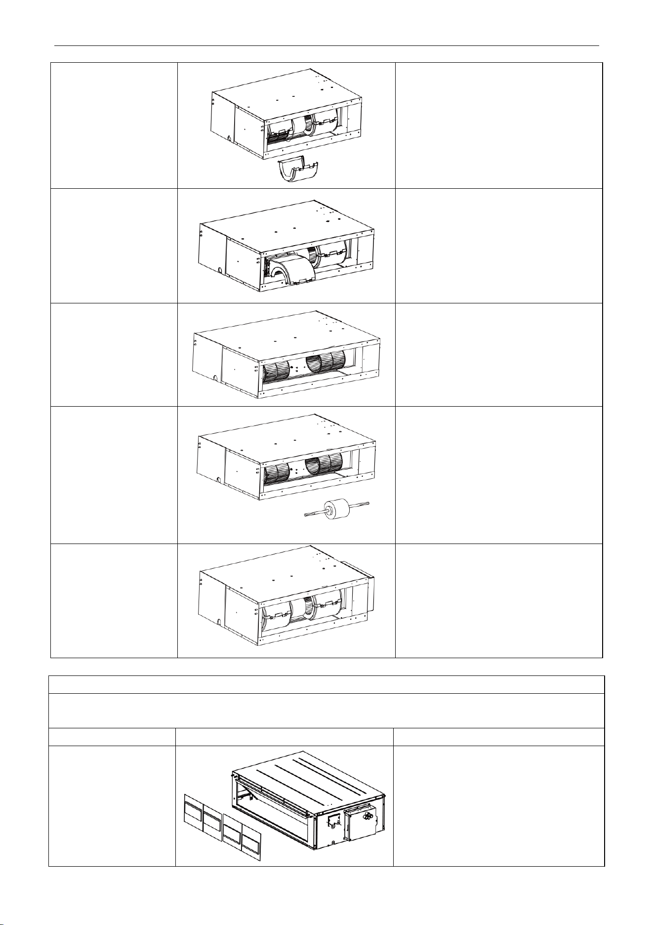
U-Match Series DC Inverter Service Manual
130
3. Remove the screws on
fan sub-assembly.
Remove the screws on fan sub-assembly.
4. Overturn the propeller
housing
Rotate the propeller housing to the air inlet
according to arrow direction.
5. Loosen the fan and
motor.
Use inner hexagonal spanner to loosen the
screws on fan and remove the clamp fixing
the motor.
6. Replace the motor
Firstly, disengage the motor from motor
support. Then, sequentially disengage the
fan sub-assembly form the motor shaft.
Remove the motor from the air inlet and
replace with new motor. In which, for the
motor with automatic motor support, the
motor support shall be removed in advance
and then changed to the unit.
7. Assemble the unit in
reverse to the
disassembly procedures
Assemble the unit in reverse to the
disassembly procedures and energize it for
testing.
Disassembly of filter screen for return air
Remark: Make sure that the power supply is cut off before disassembling and protect all the parts during disassembly. Do not
put filter screen near the high temperature heat source.
Step
Illustration
Handling Instruction
Disassembly of filter
screen for return air
Compress the filter screen for return air down
on the guide slot sponge, and remove
according to the direction shown by the
arrow. There are 2 filter screen for return air.
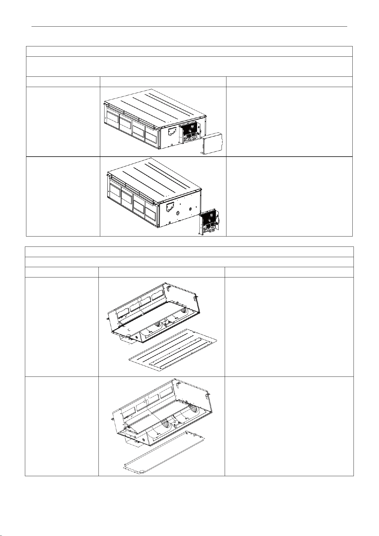
U-Match Series DC Inverter Service Manual
131
Disassembly of electrical parts box cover panel and electrical parts box
Remark: Make sure that the power supply is cut off before disassembling and protect all the parts during disassembly,
especially the electrical components. Do not dampen or hit them.
Step
Illustration
Handling Instruction
1. Disassembly of electric
box cover
Disassemble the screw according to the
position shown in the circle and the box and
remove the electric box in the direction of the
arrow.
2. Disassembly of electric
parts box
Disassemble the fastening screw and remove
the electrical parts box. (As is shown in the
graph, there are 2 fastening screws in the circle
and the screws in the direction of arrow shall
be disassembled too.)
Disassembly of water-containing plate
Remark: Make sure that the power supply is cut off before disassembling and protect all the parts during disassembly.
Step
Illustration
Handling Instruction
1.Disassembly of cover
plate
Disassemble the fastening screws on the cover
plate and remove the cover plate. (As is shown
in the graph, circle represents 6 fastening
screws under the cover plate and the box
represents two fastening screws on
water-containing plate symmetrically arranged
both on left and right.)
2.Disassembly of
water-containing plate
Disassemble the fastening screws on the
water-containing plate, pull upward and remove
the water-containing plate. Disassembled
water-containing plate is shown in the graph.
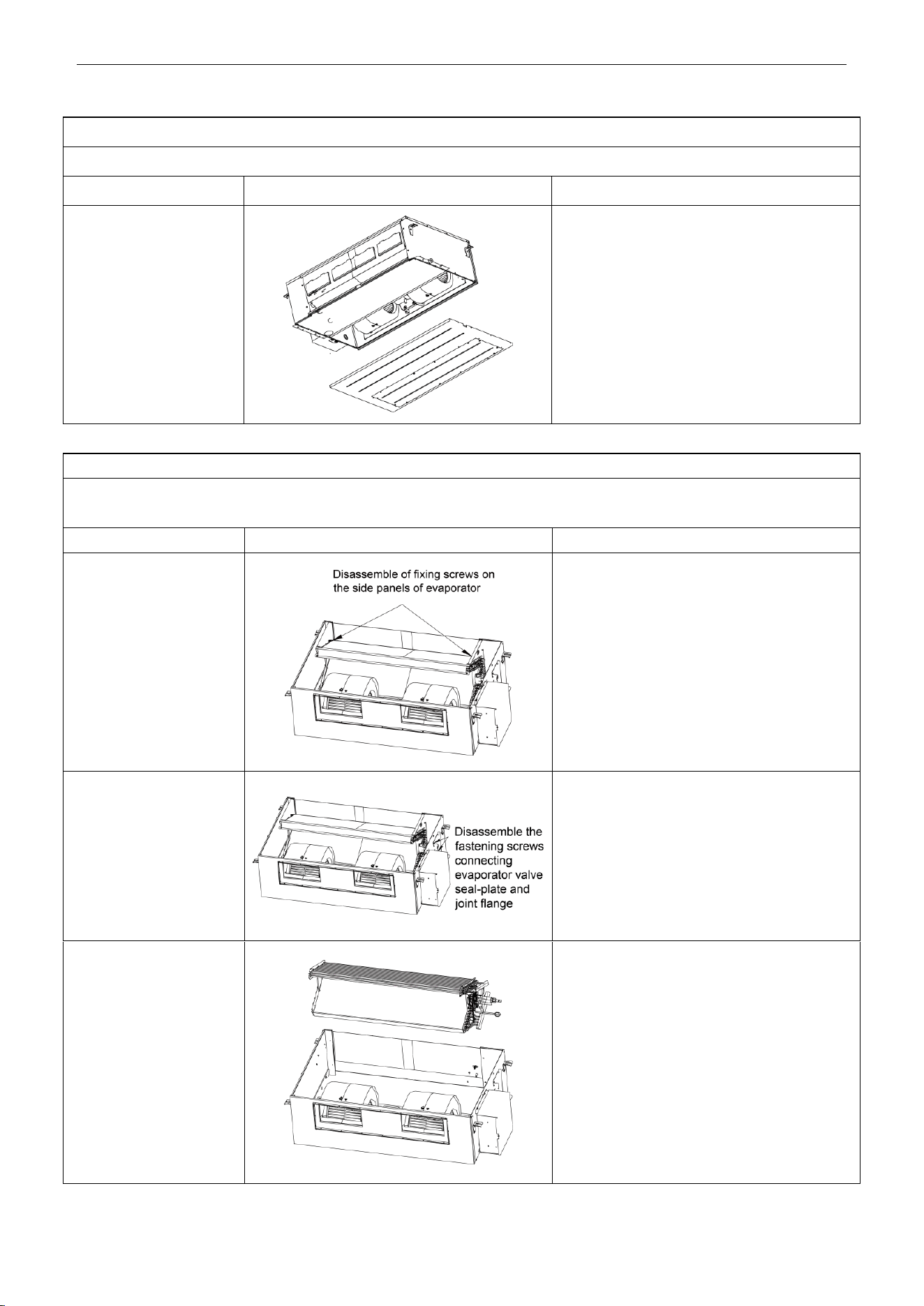
U-Match Series DC Inverter Service Manual
132
Disassembly of fan and motor
Remark: Make sure that the power supply is cut off before disassembling and protect all the parts during disassembly.
Step
Illustration
Handling Instruction
Disassembly of fan motor
Disassemble the fixing screws on the fan
components. (As is shown in graph, circle
represents 6 screws.)
Disassemble the fastening screws on the fan
and motor. Remove the fan. (As is shown in the
graph, box represents screws.)
Disassembly of evaporator
Remark: Make sure that the power supply is cut off and protect the copper tube and aluminum fin. If the time for disassembly
shall be long, put the copper tube under pressurized condition.
Step
Illustration
Handling Instruction
1. Disassembly of fixing
screws on the side panels
of evaporator
Disassemble the fastening screw connecting
left and right side panels on the evaporator and
the upper cover plate. (As is shown in the
arrows direction in graph.)
2. Disassemble fastening
screws connecting
evaporator valve
seal-plate and joint flange
Disassemble the fastening screws on the valve
seal-plate and remove the valve seal-plate.
Disassemble the fastening screws on the
evaporators’ joint flange. (As is shown in the
graph, box represents fastening screws on
seal-plates while circle the fastening screws on
joining flange.
3. Removal of evaporator
Remove the evaporator. Removed evaporator
is shown in the graph.
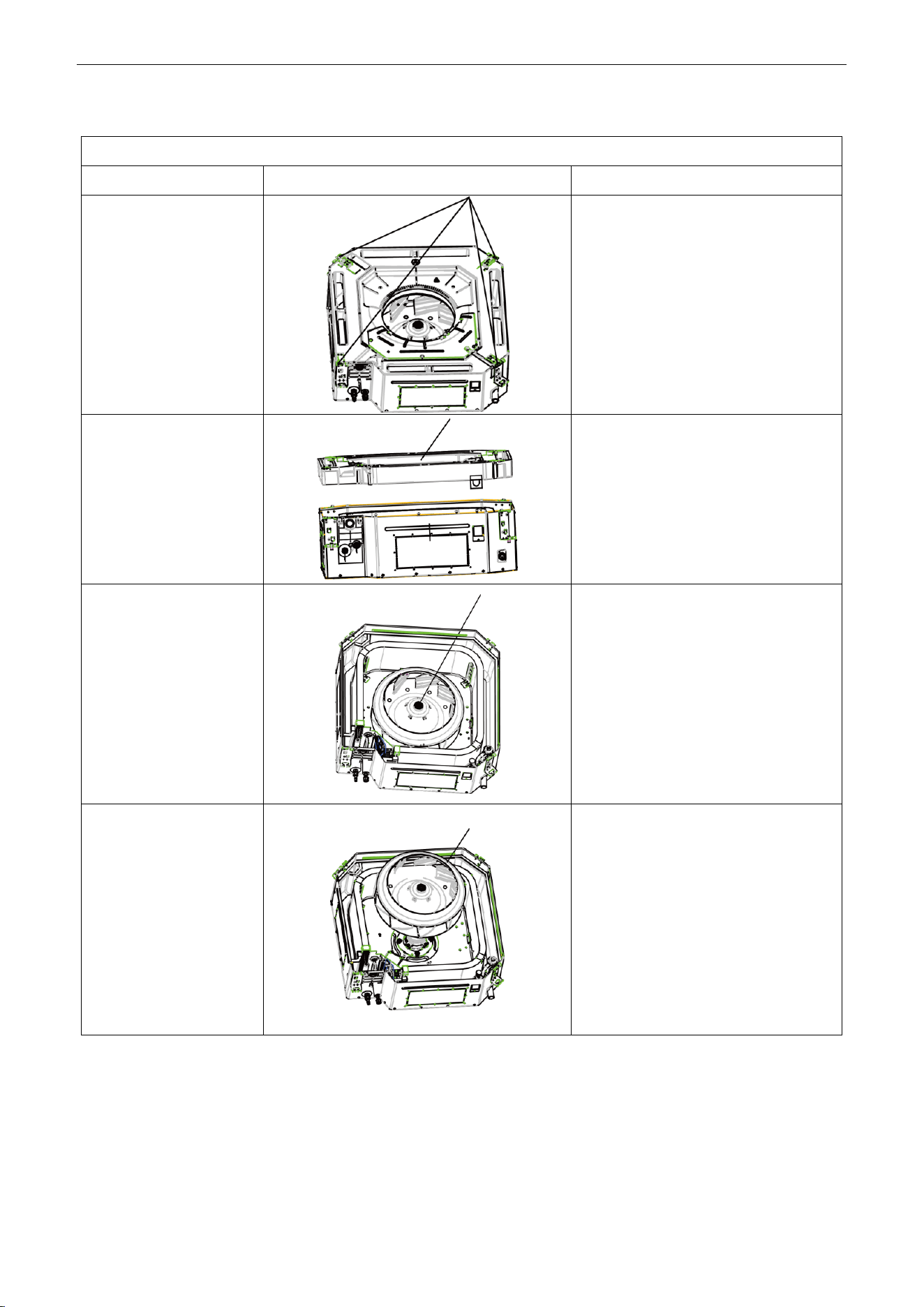
U-Match Series DC Inverter Service Manual
133
4.2.2 Cassette-type Unit
Removal and Assembly of Fan Motor
Step
Illustration
Handling Instruction
1. Loosen the screws
fixing the water tray
Use screwdriver to loosen the screws
fixing the water tray.
2. Remove the water tray
Remove the water tray.
3. Loosen the bolts fixing
the fan
Use spanner to loosen the bolts fixing the
fan.
4. Remove the fan
Remove the fan.
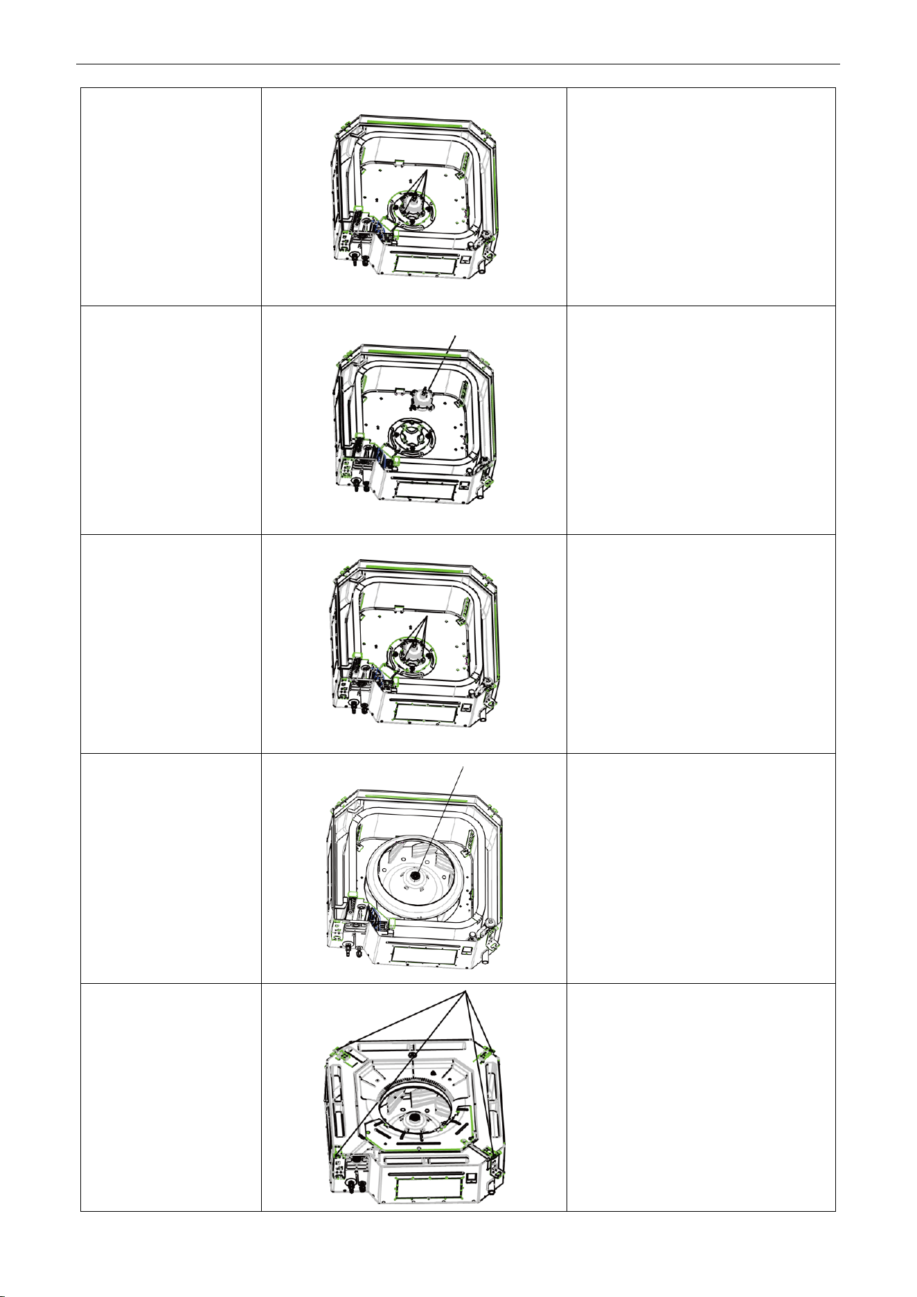
U-Match Series DC Inverter Service Manual
134
5. Loosen the screws
fixing the motor
Use screwdriver to loosen the screws
fixing the motor.
6. Remove the motor and
replace it
Remove the motor and replace it.
7. Tighten the screws
fixing the motor
Use screwdriver to tighten the screws
fixing the motor.
8. Mount the fan and
tighten the fixing bolts
Mount the fan and use spanner to tighten
the bolts fixing the fan.
9. Mount the water tray
and tighten the screws
Use screwdriver to loosen the screws
fixing the water tray.
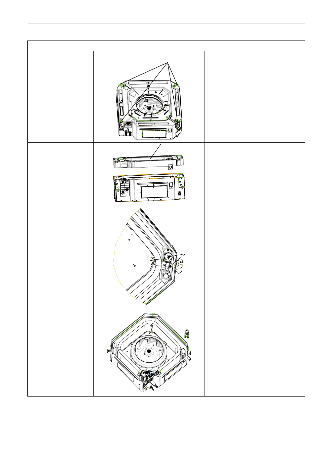
U-Match Series DC Inverter Service Manual
135
Removal and Installation of Drainage Pump
Step
Illustration
Handling Instruction
1. Loosen the screws
fixing the water tray
Use screwdriver to loosen the screws
fixing the water tray.
2. Remove the water tray
Remove the water pump and replace it.
3. Pull out the water outlet
pipe and loosen the
screws fixing the water
pump.
Pull out the water outlet pipe and use
screwdriver to loosen the screws fixing the
water pump.
4. Take out the pump and
replace it
Take out the pump and replace it
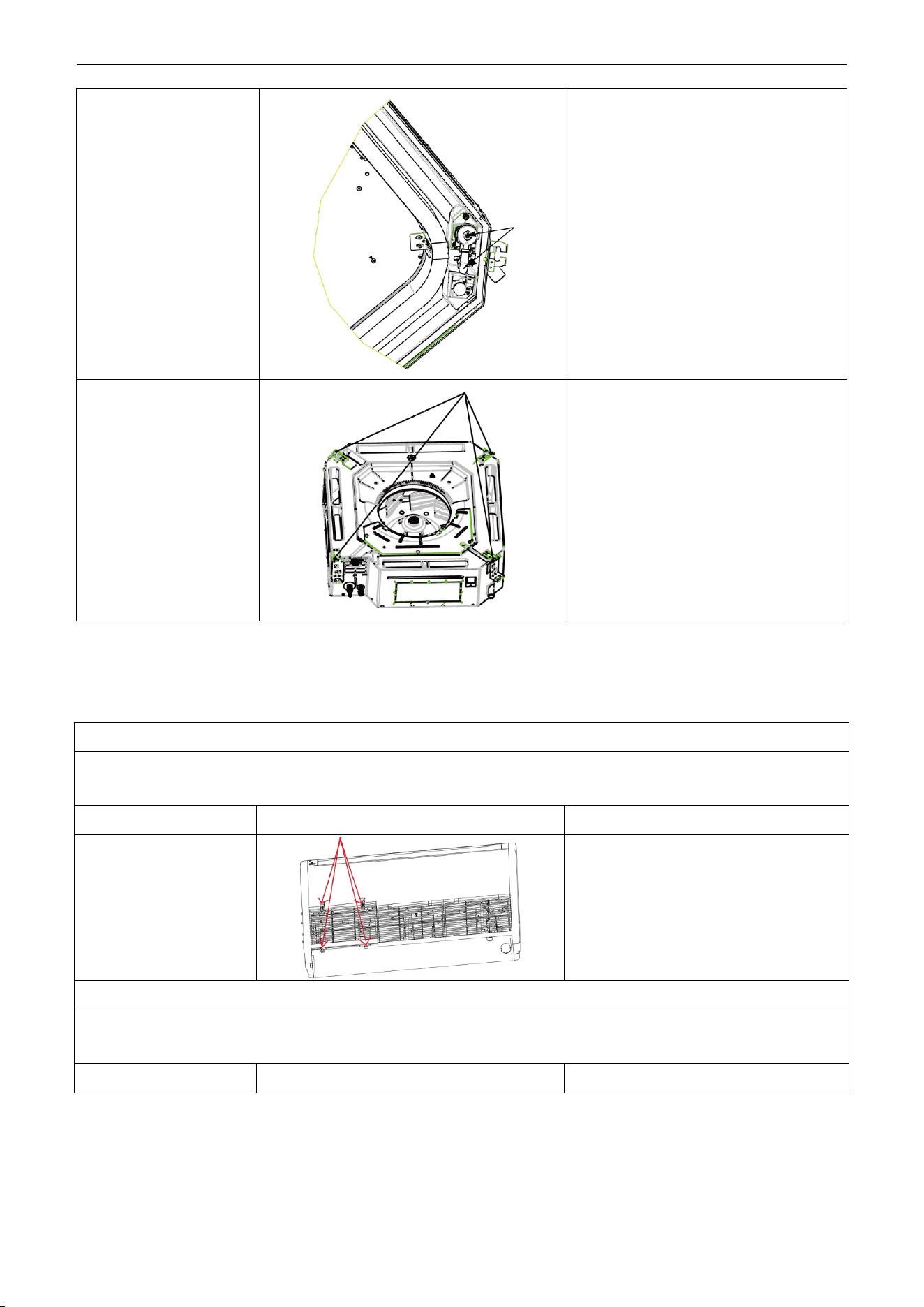
U-Match Series DC Inverter Service Manual
136
5. Connect the drainage
pipe and tighten the
screws fixing the water
pump.
Connect the drainage pipe and use
screwdriver to tighten the screws fixing the
water pump.
6. Mount the water tray
and tighten the screws
Use screwdriver to loosen the screws
fixing the water tray.
4.2.3 Floor Ceiling Type
Model: UMAT30HP230V1AF/UMAT36HP230V1AF/UMAT42HP230V1AF
Disassembly of panel grating module
Remark: Make sure that the power supply is cut off before disassembling and protect all the parts during disassembly. Do not
put filter screen near the high temperature heat source.
Step
Illustration
Handling Instruction
Disassembly of sub-assy
of front grill
1. Unscrew the 2 clasps of the upper grill
and the 2 screws of the clasps.
2. Open the grill, disassemble the 2 down
clasps to remove the grill.
Disassembly of right and left finishing plates
Remark: Make sure the power supply is cut off before disassembling and protect all the parts during disassembly. Do not
scratch the outer parts.
Step
Illustration
Handling Instruction
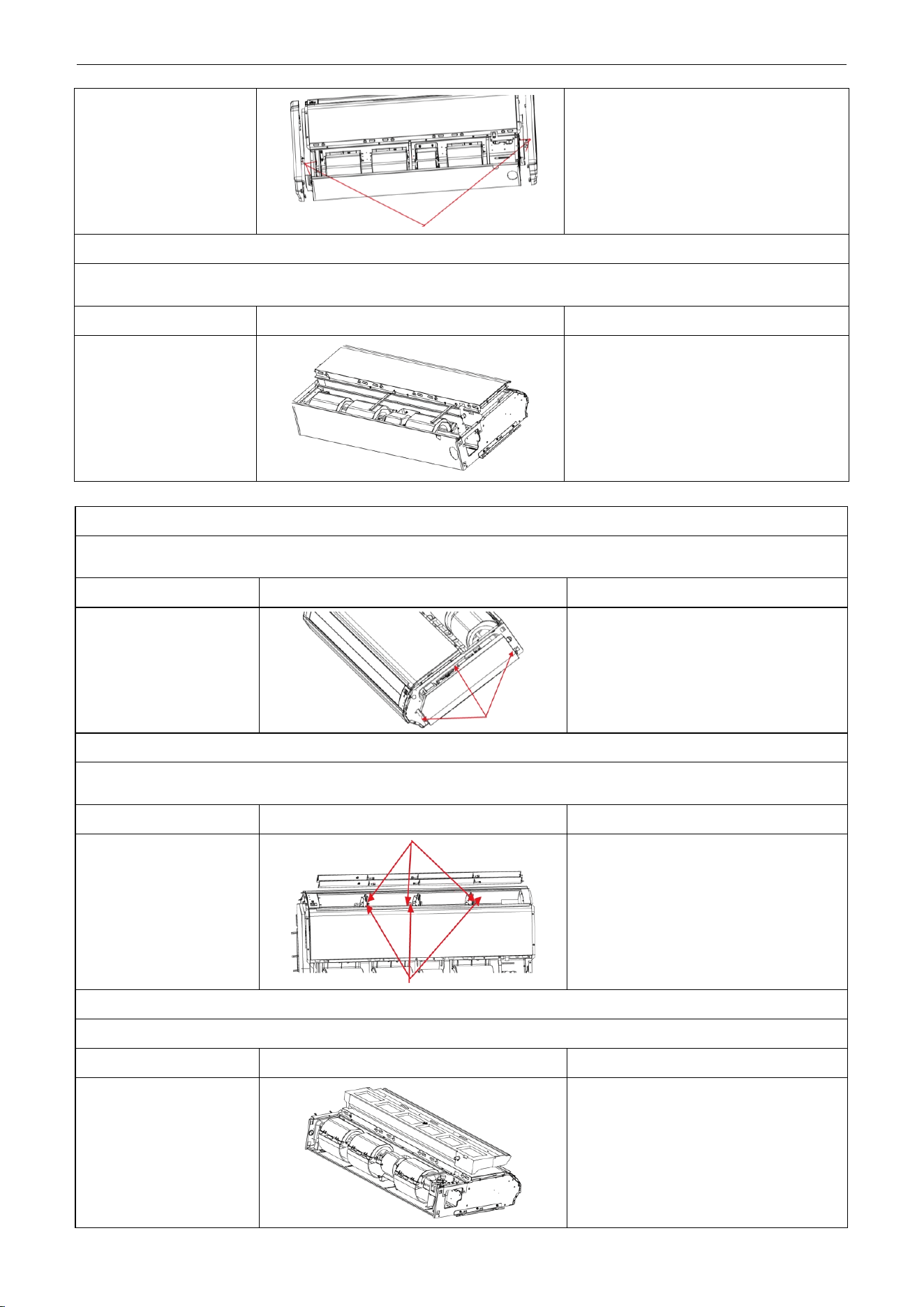
U-Match Series DC Inverter Service Manual
137
Disassembly of right and
left finishing plates
Disassemble the screws as shown in the
graph with screwdriver and then push
upward to remove the right and left finishing
plates. (As is shown in the graph, arrow
represents the position of screws.)
Disassembly of panel parts
Remark: Make sure the power supply is cut off before disassembling and protect all the parts during disassembly. Do not
scratch the outer parts.
Step
Illustration
Handling Instruction
Disassembly of panel
parts
Unscrew the 3 sides’ screws on the cover
to remove the cover.
Disassembly of sub-assy of electric box
Remark: Make sure that the power supply is cut off before disassembling and protect all the parts during disassembly,
especially the components inside the box in case of water and hit.
Step
Illustration
Handling Instruction
Disassembly of electric
box cover
Disassemble 3 screws as shown by the
arrow in the graph on left and remove the
electric box cover.
Disassembly of air deflecting plate modules
Remark: Make sure the power supply is cut off before disassembling and protect all the parts during disassembly, especially
the joints of the air deflecting plate.
Step
Illustration
Handling Instruction
Disassembly of sub-assy
of air deflecting plate
Remove the air deflecting plates from the
air deflecting plate support assembly, and
then remove both ends from the air
sweeping motor. joint (As is shown in the
graph, arrow represents the support
assembly and circle the air sweeping
motor joint.)
Disassemble of water-containing plate modules
Remark: Make sure the power supply is cut off before disassembling and protect all the parts during disassembly.
Step
Illustration
Handling Instruction
Disassemble of
water-containing plate
modules
Remove the water-containing plate modules.
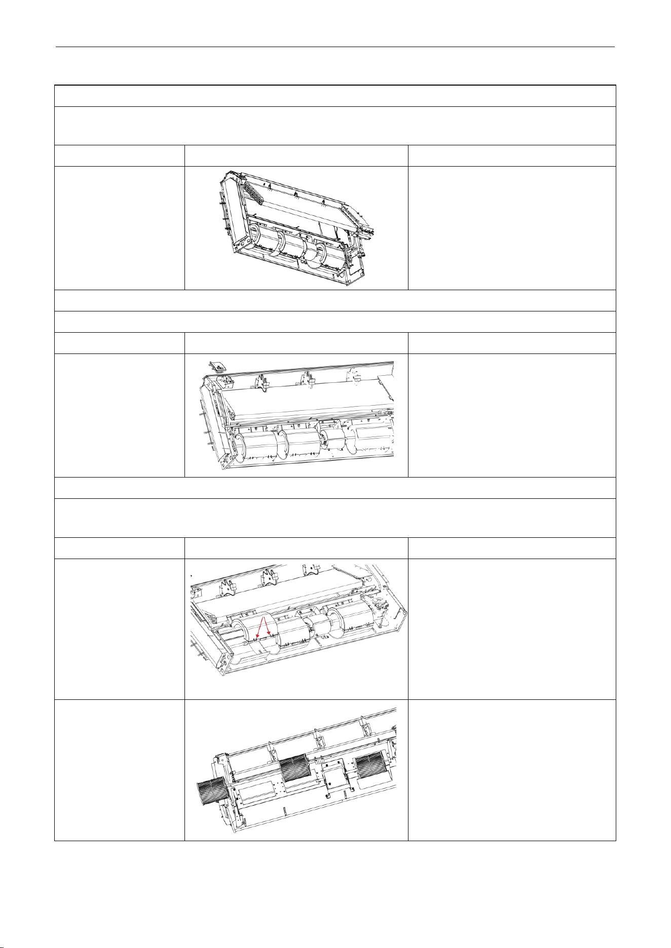
U-Match Series DC Inverter Service Manual
138
Disassembly of evaporator components
Remark: Make sure that the power supply is cut off and protect the copper tube and aluminum fin. If the time for disassembly
shall be long, seal the copper tube.
Step
Illustration
Handling Instruction
Disassembly of
evaporator components
Unscrew the 6 screws of evaporator, 3
screws of water groove press board and the
2 screws of water board to remove the
evaporator.
Disassembly of fixing plate sub-assy for air sweeping fans
Remark: Make sure that the power supply is cut off before disassembling and protect all the parts during disassembly.
Step
Illustration
Handling Instruction
Disassembly of fixing
plate sub-assy for air
sweeping fans
Remove the display board, mounting
support and mounting plate of swing motor
in turn.
Disassembly of fan and motor components
Remark: Make sure that the power supply is cut off before disassembling and protect all the parts during disassembly,
especially the fastening screws for fans.
Step
Illustration
Handling Instruction
1. Disassembly of front
and back scroll cases
Press the buckle at the joints of front and
back scroll cases with hands and pull
upward to remove the front scroll case.
Then remove the screws on the back scroll
case. Lift the buckle of back scroll case with
hands and remove it. (As is shown in the
graph, circle represents 2 screws on left
and right.)
2. Disassembly of fans
Unscrew the 2 screws of coupling, take out
the rotating shaft and louver, then loosen
the tighten screw of louver to remove the
louver.
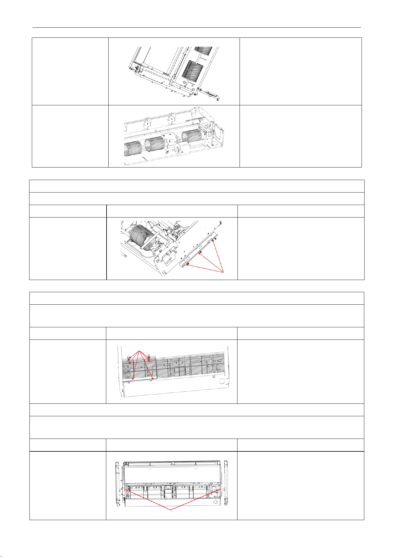
U-Match Series DC Inverter Service Manual
139
3. Disassembly of bearing
fixing plates
Unscrew the 3 screws and 2 nuts of support
to remove the mounting support.
4. Disassembly of motor
Loosen the 2 screws of the motor attaching
clamp, remove the motor attaching clamp
and motor attaching clamp subassembly to
remove the motor.
Disassembly of right and left fixing plates
Remark: Make sure that the power supply is cut off before disassembling and protect all the parts during disassembly.
Step
Illustration
Handling Instruction
Disassembly of right and
left fixing plates
Disassemble the bolts on right and left fixing
plates with tools. (As is shown by the arrow in
the graph.)
Model: UMAT18HP230V1AF/UMAT24HP230V1AF/UMAT48HP230V1AF
Disassembly of panel grating module
Remark: Make sure that the power supply is cut off before disassembling and protect all the parts during disassembly. Do not
put filter screen near the high temperature heat source.
Step
Illustration
Handling Instruction
Disassembly of sub-assy
of front grill
1. Unscrew the 2 clasps of the upper grill and
the 2 screws of the clasps.
2. Open the grill, disassemble the 2 down
clasps to remove the grill.
Disassembly of right and left finishing plates
Remark: Make sure the power supply is cut off before disassembling and protect all the parts during disassembly. Do not
scratch the outer parts.
Step
Illustration
Handling Instruction
Disassembly of right and
left finishing plates
Disassemble the screws as shown in the
graph with screwdriver and then push upward
to remove the right and left finishing
plates.(As is shown in the graph, arrow
represents the position of screws.)
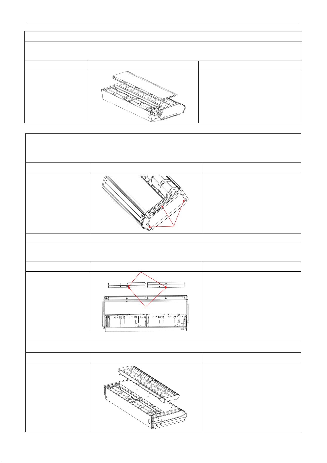
U-Match Series DC Inverter Service Manual
140
Disassembly of panel parts
Remark: Make sure the power supply is cut off before disassembling and protect all the parts during disassembly. Do not
scratch the outer parts.
Step
Illustration
Handling Instruction
Disassembly of panel
parts
Unscrew the 3 sides’ screws on the cover to
remove the cover.
Disassembly of sub-assy of electric box
Remark: Make sure that the power supply is cut off before disassembling and protect all the parts during disassembly,
especially the components inside the box in case of water and hit.
Step
Illustration
Handling Instruction
1. Disassembly of electric
box cover
Disassemble 3 screws as shown by the
arrow in the graph on left and remove the
electric box cover.
Disassembly of air deflecting plate modules
Remark: Make sure the power supply is cut off before disassembling and protect all the parts during disassembly, especially
the joints of the air deflecting plate.
Step
Illustration
Handling Instruction
Disassembly of sub-assy
of air deflecting plate
Remove the air deflecting plates from the
air deflecting plate support assembly, and
then remove both ends from the air
sweeping motor. joint (As is shown in the
graph, arrow represents the support
assembly and circle the air sweeping
motor joint.)
Disassemble of water-containing plate modules
Remark: Make sure the power supply is cut off before disassembling and protect all the parts during disassembly.
Step
Illustration
Handling Instruction
Disassemble of
water-containing plate
modules
Remove the water-containing plate
modules.
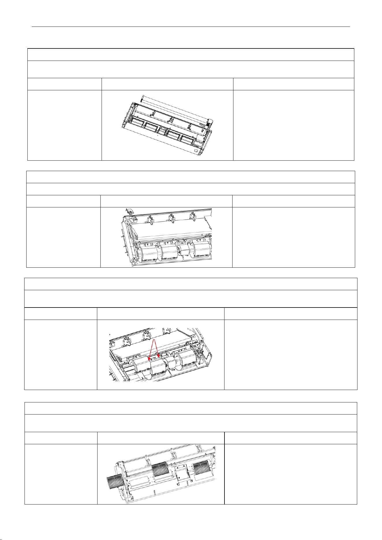
U-Match Series DC Inverter Service Manual
141
Disassembly of evaporator components
Remark: Make sure that the power supply is cut off and protect the copper tube and aluminum fin. If the time for disassembly
shall be long, seal the copper tube.
Step
Illustration
Handling Instruction
Disassembly of
evaporator components
Unscrew the 6 screws of evaporator, 3
screws of water groove press board and the
2 screws of water board to remove the
evaporator.
Disassembly of fixing plate sub-assy for air sweeping fans
Remark: Make sure that the power supply is cut off before disassembling and protect all the parts during disassembly.
Step
Illustration
Handling Instruction
Disassembly of fixing
plate sub-assy for air
sweeping fans
Remove the display board, mounting support
and mounting plate of swing motor in turn.
Disassembly of fan and motor components
Remark: Make sure that the power supply is cut off before disassembling and protect all the parts during disassembly, especially
the fastening screws for fans.
Step
Illustration
Handling Instruction
Disassembly of front and
back scroll cases
Press the buckle at the joints of front and back
scroll cases with hands and pull upward to
remove the front scroll case. Then remove the
screws on the back scroll case. Lift the buckle of
back scroll case with hands and remove it. (As is
shown in the graph, circle represents 2 screws on
left and right.)
Disassembly of fan and motor components
Remark: Make sure that the power supply is cut off before disassembling and protect all the parts during disassembly, especially
the fastening screws for fans.
Step
Illustration
Handling Instruction
1. Disassembly of fans
Unscrew the 2 screws of coupling, take out the
rotating shaft and louver, then loosen the tighten
screw of louver to remove the louver.
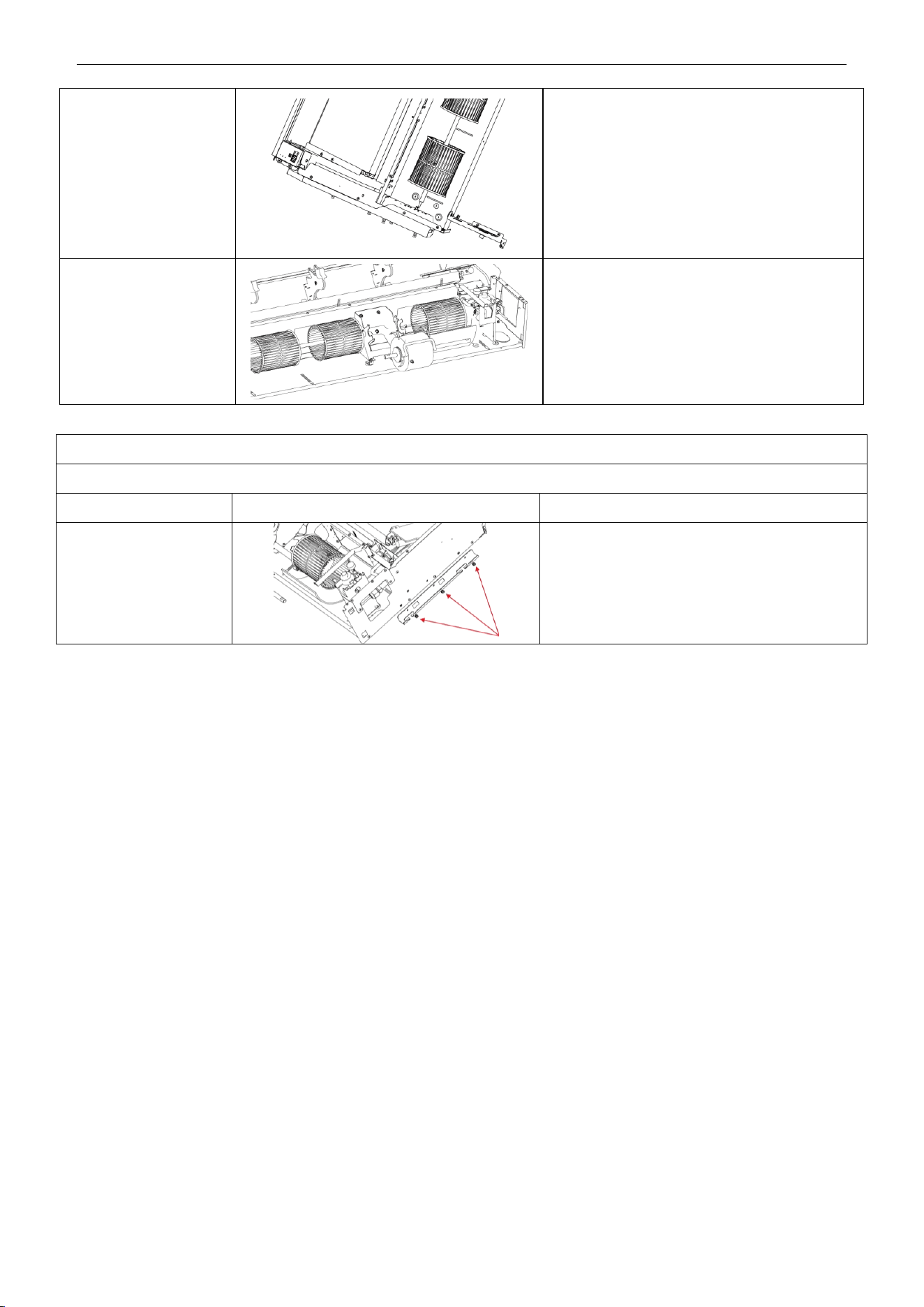
U-Match Series DC Inverter Service Manual
142
2. Disassembly of
bearing fixing plates
Unscrew the 3 screws and 2 nuts of support to
remove the mounting support
3. Disassembly of motor
Loosen the 2 screws of the motor attaching
clamp, remove the motor attaching clamp and
motor attaching clamp subassembly to remove
the motor.
Disassembly of right and left fixing plates
Remark: Make sure that the power supply is cut off before disassembling and protect all the parts during disassembly.
Step
Illustration
Handling Instruction
Disassembly of right and
left fixing plates
Disassemble the bolts on right and left fixing
plates with tools. (As is shown by the arrow in the
graph.)
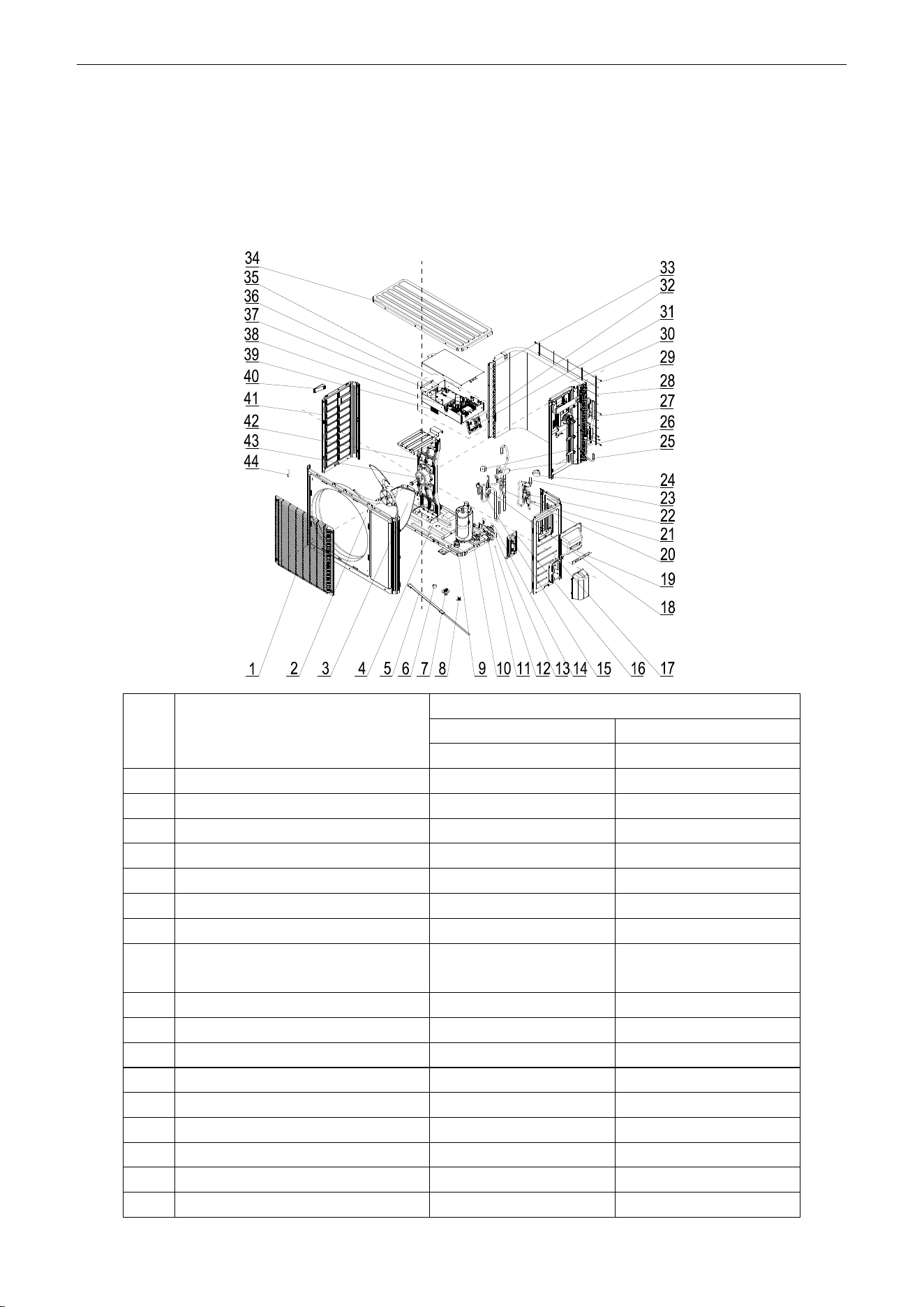
U-Match Series DC Inverter Service Manual
143
5 EXPLODED VIEWS AND SPARE PART LIST
5.1 Outdoor Unit
Model: UMAT18HP230V1AO Exploded Views and spare
parts list:
NO.
Name of Part
UMAT18HP230V1AO
Product Code
CF090W0751
Part Code
Quantity
1
Front Grill
01473049
1
2
Front Panel
01535013P
1
3
Axial Flow Fan
10335008
1
4
Chassis Sub-assy
01195200028P
1
5
Electrical Heater
7651300403
1
6
Drainage hole Cap
06813401
3
7
Drainage Connecter
06123401
1
8
Compressor Overload
Protector(External)
00180030/00183051/
00183032/00183031
1
9
Compressor Gasket
76710247
3
10
Compressor and Fittings
00105249G
1
11
Cut off Valve
071302392
1
12
Cut off Valve Sub-Assy
07133060
1
13
Cut off Valve
07130239
1
14
Cut off Valve Sub-Assy
07335200016
1
15
Pressure Protect Switch
46020003
1
16
Valve Support Assy
01715010P
1
17
Right Side Plate
0130509403P
1
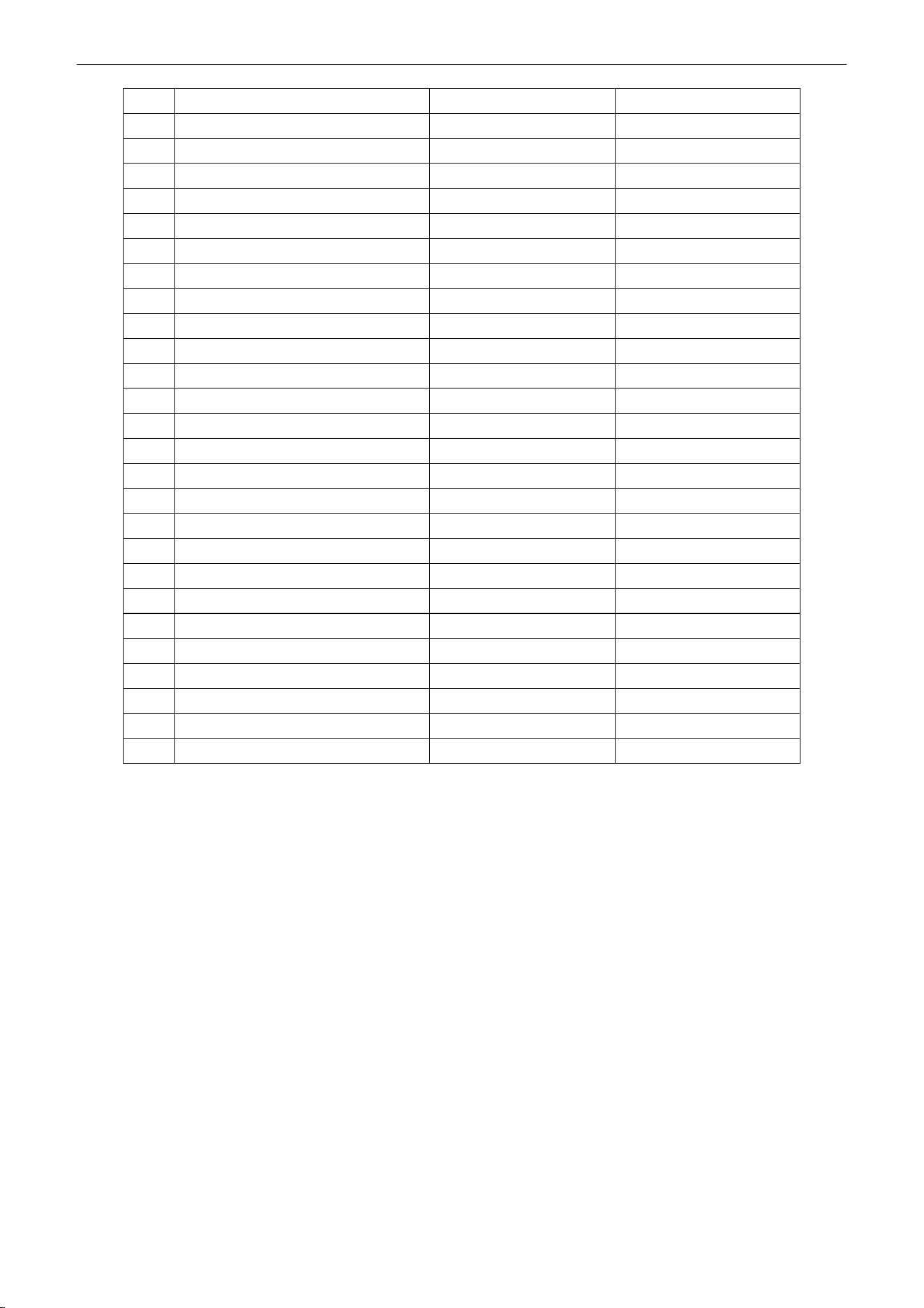
U-Match Series DC Inverter Service Manual
144
18
Silencer
07245007
1
19
Handle Assy
02113032P
1
20
Strainer
07212403
1
21
Strainer
07220019
1
22
Strainer
0721004501
1
23
Electronic Expansion Valve
07134601
1
24
Electric Expand Valve Fitting
4300876704
1
25
4-Way Valve
430004032
1
26
Magnet Coil
4300040045
1
27
Inductance
4312002001
1
28
Rear Grill
01473043
1
29
Clapboard Sub-Assy
01232902
1
30
Condenser Assy
01125200189
1
31
Terminal Board
420111451
1
32
Terminal Board
420101852
1
33
Supporting Board(Condenser)
01795010
1
34
Coping
01255005P
1
35
Electric Box Assy
01395200486
1
36
Main Board
30224000024
1
37
Main Board
30221000009
1
38
Filter Board
30221000008
1
39
Radiator
49018000044
1
40
Left Handle
26233053
1
41
Left Side Plate
01305093P
1
42
Motor Support Assy
01805200173
1
43
Fan Motor
1570280204
1
44
Temperature Sensor
3900028020G
1
Above data is subject to change without notice, pls reference the SP in global service website.
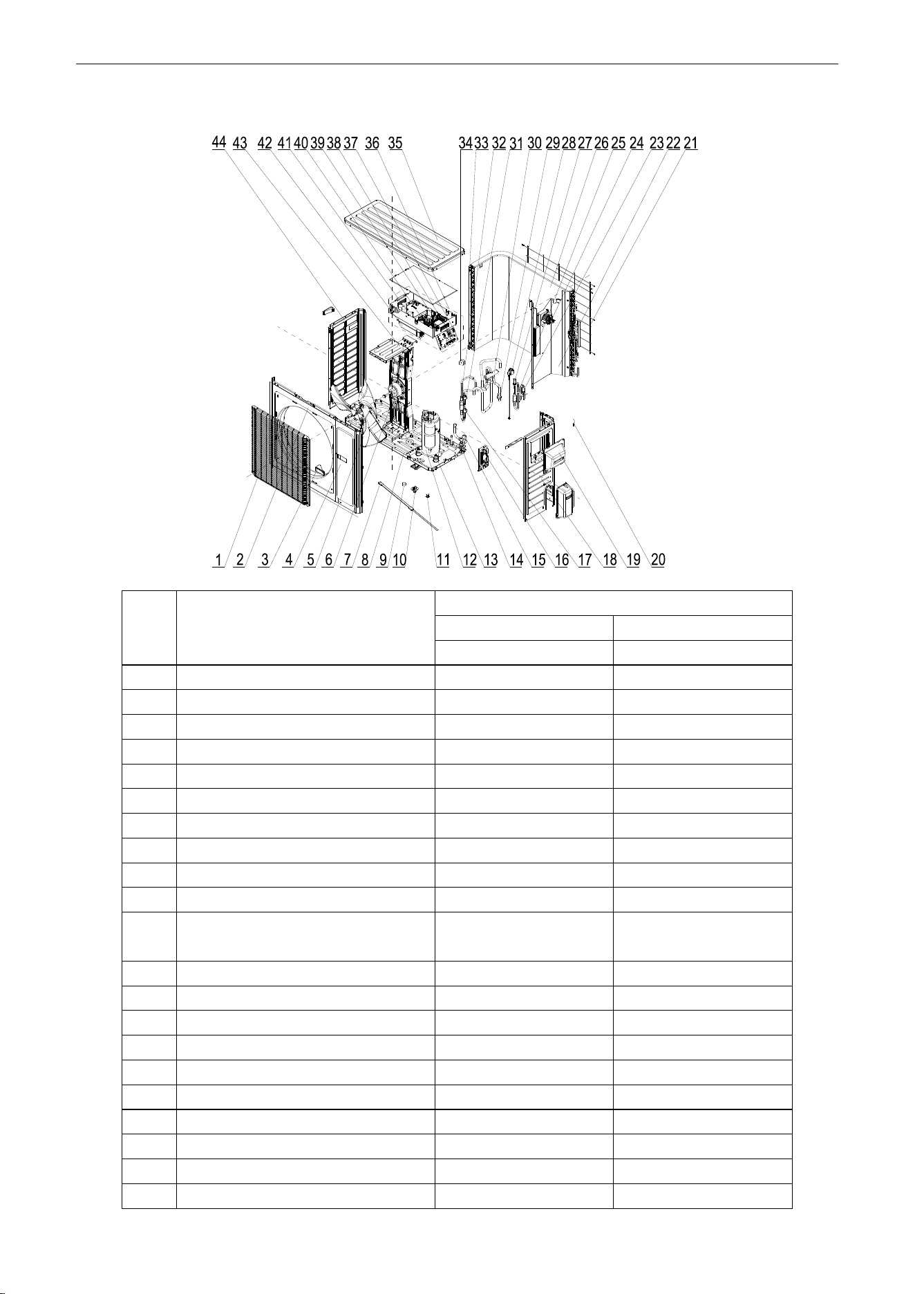
U-Match Series DC Inverter Service Manual
145
Model: UMAT24HP230V1AO Exploded Views and spare
parts list:
NO.
Name of Part
UMAT24HP230V1AO
Product Code
CF090W0761
Part Code
Quantity
1
Front Grill
01473050
1
2
Cabinet
01435004P
1
3
Left Handle
26235401
2
4
Front Side Plate
01305086P
1
5
Axial Flow Fan
10335014
1
6
Fan Motor
15702802
1
7
Electrical Heater(Compressor)
7651873209
1
8
Chassis Sub-assy
0119520001301P
1
9
Drainage hole Cap
06813401
3
10
Drainage Connecter
06123401
1
11
Compressor Overload
Protector(External)
00180030/00183051/
00183032/00183031
1
12
Compressor and Fittings
0010505701
1
13
Compressor Gasket
76713066
3
14
Valve
071302391
1
15
Cut off Valve
07133157
1
16
Valve Support Sub-Assy
0171501201P
1
17
Pressure Protect Switch
4602000902
1
18
Right Side Plate Sub-Assy
01315200069P
1
19
Handle Assy
02113032P
1
20
Temperature Sensor
3900028020G
1
21
Rear Grill
01475013
1
U-Match Series DC Inverter Service Manual
146
22
Clapboard Sub-Assy
01245200010
1
23
Strainer
07225088
1
24
PFC Inductance
43128003
1
25
Bidirection Strainer
07220016
1
26
Condenser Assy
01125200184
1
27
Electronic Expansion Valve
07334447
1
28
Electric Expand Valve Fitting
4304413208
1
29
Strainer
07215201
1
30
4-way Valve
4300008201
1
31
Pressure Protect Switch
4602001539
1
32
Silencer
07245012
1
33
Condenser Support Plate
01175092
1
34
Magnet Coil
4300040045
1
35
Top Cover Sub-Assy
01255007
1
36
Electric Box Assy
01395200487
1
38
Terminal Board
420111451
1
37
Terminal Board
420101852
1
39
Main Board
30224000026
1
40
Filter Board
30221000007
1
41
Main Board
30221000010
1
42
Radiator
49018000042
1
43
Motor Support Assy
01805200166
1
44
Left Side Plate
01305043P
1
Above data is subject to change without notice, pls reference the SP in global service website.
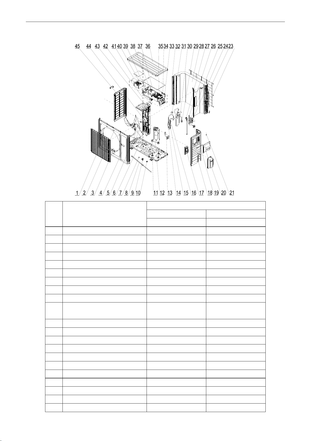
U-Match Series DC Inverter Service Manual
147
Model: UMAT30HP230V1AO Exploded Views and spare
parts list:
NO.
Name of Part
UMAT30HP230V1AO
Product Code
CF090W0830
Part Code
Quantity
1
Front Grill
01473050
1
2
Cabinet
01435004P
1
3
Left Handle
26235401
2
4
Front Side Plate
01305086P
1
5
Axial Flow Fan
10335014
1
6
Chassis Sub-assy
01195200013P
1
7
Drainage hole Cap
06813401
3
8
Electrical Heater(Compressor)
7651873209
1
9
Drainage Connecter
06123401
1
10
Compressor Overload
Protector(External)
00180030/00183051/
00183032/00183031
1
11
Compressor Gasket
76713066
3
12
Compressor and Fittings
0010505701
1
13
Cut off Valve
07133157
1
14
Silencer
07245012
1
15
Pressure Protect Switch
4602000902
1
16
Pressure Protect Switch
46020003
1
17
Valve Support Sub-Assy
0171501201P
1
18
Right Side Plate Sub-Assy
01315200069P
1
19
Cut off Valve
071302391
1
20
Handle Assy
02113032P
1
21
Temperature Sensor
3900028020G
1
U-Match Series DC Inverter Service Manual
148
22
Rear Grill
01475013
1
23
Clapboard Sub-Assy
01245200006
1
24
Strainer
07225088
1
25
Bidirection Strainer
07220016
1
26
Electronic Expansion Valve
07334447
1
27
Electric Expand Valve Fitting
4304413208
1
28
Condenser Assy
01125200182
1
29
Strainer
07215201
1
30
4-way Valve
4300008201
1
31
Magnet Coil
4300040045
1
32
Condenser Support Plate
01175092
1
33
Terminal Board
420101852
1
34
Terminal Board
420111451
1
35
Main Board
30224000038
1
36
Top Cover Sub-Assy
01255007
1
37
Main Board
30221000010
1
38
Filter Board
30221000007
1
39
Radiator
49018000042
1
40
PFC Inductance
43128003
1
41
Inductance Box Sub-assy
01395200176
1
42
Electric Box Assy
01395200488
1
43
Motor Support Assy
01805200160
1
44
Fan Motor
15702802
1
45
Left Side Plate
01305043P
1
Above data is subject to change without notice, pls reference the SP in global service website.
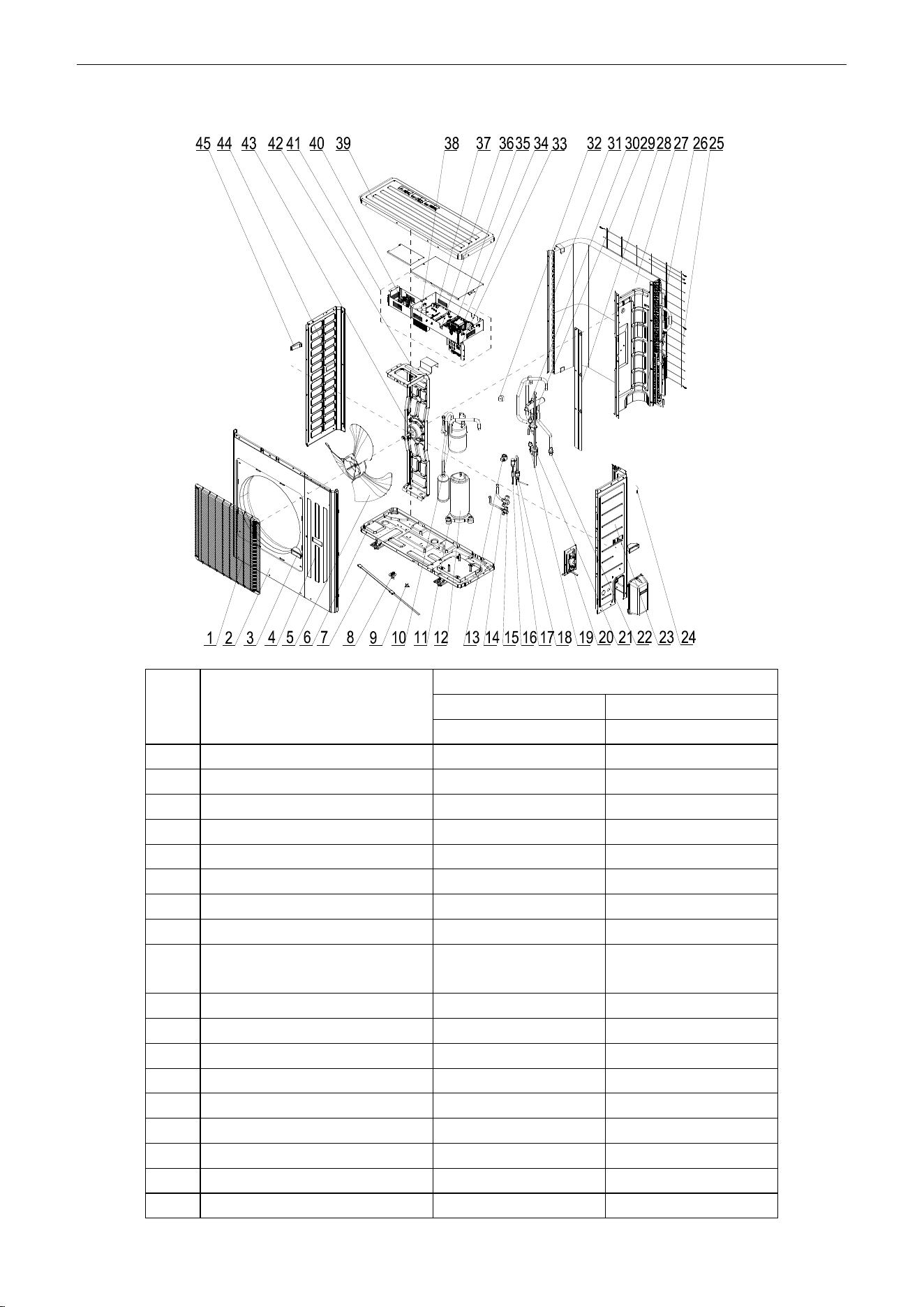
U-Match Series DC Inverter Service Manual
149
Model: UMAT36HP230V1AO Exploded Views and spare parts list:
NO.
Name of Part
UMAT36HP230V1AO
Product Code
CF090W0771
Part Code
Quantity
1
Front Grill
01574106
1
2
Cabinet
01435007P
1
3
Handle
26235253
2
4
Front Side Plate Sub-Assy
01305065P
1
5
Axial Flow Fan
10335010
1
6
Chassis Sub-assy
01195244P
1
7
Electrical Heater(Compressor)
7651873209
1
8
Drainage Joint
26113009
1
9
Compressor Overload
Protector(External)
00180030/00183051/
00183032/00183031
1
10
Gas-liquid Separator Sub-Assy
07255201
1
11
Compressor Gasket
76713066
3
12
Compressor
00205200003
1
13
Electric Expand Valve Fitting
4300010839
1
14
Cut off Valve
071302391
1
15
Cut off Valve
07133157
1
16
Strainer
07213032
1
17
Strainer
07210045
1
18
Electronic Expansion Valve
07334194
1
U-Match Series DC Inverter Service Manual
150
19
Pressure Protect Switch
46020003
1
20
Valve Support Sub-Assy
01805200222P
1
21
Silencer
07245012
1
22
Strainer
07215201
1
23
Right Side Plate Sub-Assy
0131520006801P
1
24
Temperature Sensor
39008000049G
1
25
Rear Grill
01475012
1
26
Clapboard Sub-Assy
0124525303
1
27
Condenser Assy
01125200196
1
28
Baffle Plate Sub-assy
01355200016P
1
29
Pressure Protect Switch
4602000902
1
30
4-way Valve
43000338
1
31
Condenser support plate
01895242
1
32
Magnet Coil
4300040045
1
33
Terminal Board
420101852
1
34
Terminal Board
42011242
1
35
Main Board
30224000037
1
36
Filter Board
30221000007
1
37
Main Board
30221000003
1
38
Radiator
49018000047
1
39
Top Cover
0125500901P
1
40
PFC Inductance
43120011
1
41
Electric Box Assy
01395200489
1
42
Motor Support Sub-assy
01805200190
1
43
Fan Motor
1570280201
1
44
Left Side Plate
01305064P
1
45
Left Handle
26235401
1
Above data is subject to change without notice, pls reference the SP in global service website.
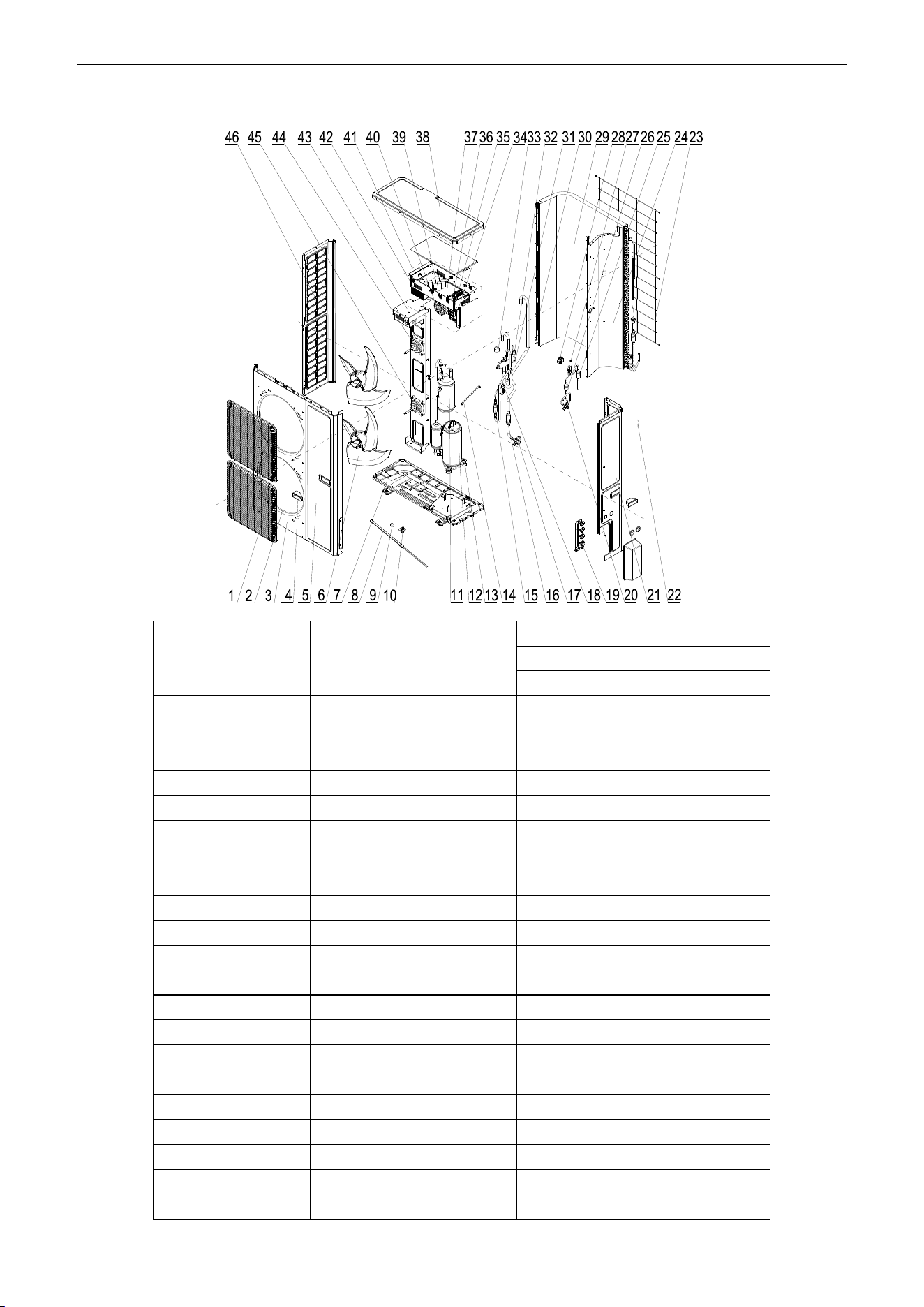
U-Match Series DC Inverter Service Manual
151
Model: UMAT42HP230V1AO Exploded Views and spare parts list:
NO.
Name of Part
UMAT42HP230V1AO
Product Code
CF090W0840
Part Code
Quantity
1
Front Grill
1574100009
2
2
Diversion Circle
10474100001
2
3
Cabinet Assy
1514100006
1
4
Handle
26235253
2
5
Front Side Plate
01314100021P
1
6
Axial Flow Fan
10434100003
2
7
Chassis Sub-assy
01195200020P
1
8
electrical heater
7651873224
1
9
Drainage hole Cap
6813401
3
10
Drainage Connecter
6123401
1
11
Gas-liquid Separator
Sub-Assy
7255201
1
12
Compressor
205200003
1
13
Compressor Gasket
76713066
3
14
Wire Clamp
2145008
1
15
Silencer
7245012
2
16
Strainer
7411100014
1
17
Cut off Valve
7133844
1
18
Pressure Protect Switch
46020003
1
19
Valve Support Sub-Assy
01805200204P
1
20
Cut off Valve
7130209
1
U-Match Series DC Inverter Service Manual
152
21
Rear Side Plate Sub-Assy
01315200088P
1
22
Temperature Sensor
3900028025G
1
23
Rear Grill
1574100004
1
24
Clapboard
1245200007
1
25
Bidirection Strainer
7220016
1
26
Strainer
7415210
1
27
Electronic Expansion Valve
7334194
1
28
Electric Expand Valve Fitting
4300010839
1
29
Condenser Assy
1125200197
1
30
Supporting Strip
1894100026
1
31
4-way Valve
43000338
1
32
Pressure Protect Switch
4602000902
1
33
Magnet Coil
4300040032
1
34
Terminal Board
420101852
1
35
Terminal Board
42011242
1
36
Main Board
30224000036
1
37
Filter Board
30221000007
1
38
Coping
01264100008P
1
39
Main Board
30221000003
1
40
PFC Inductance
43120011
1
41
Electric Box Assy
1395200490
1
42
Radiator
49018000047
1
43
Motor Support Sub-Assy
01805200185
1
44
Fan Motor
15704115
1
45
Fan Motor
1570411501
1
46
Left Side Plate
01314100013P
1
Above data is subject to change without notice, pls reference the SP in global service website.
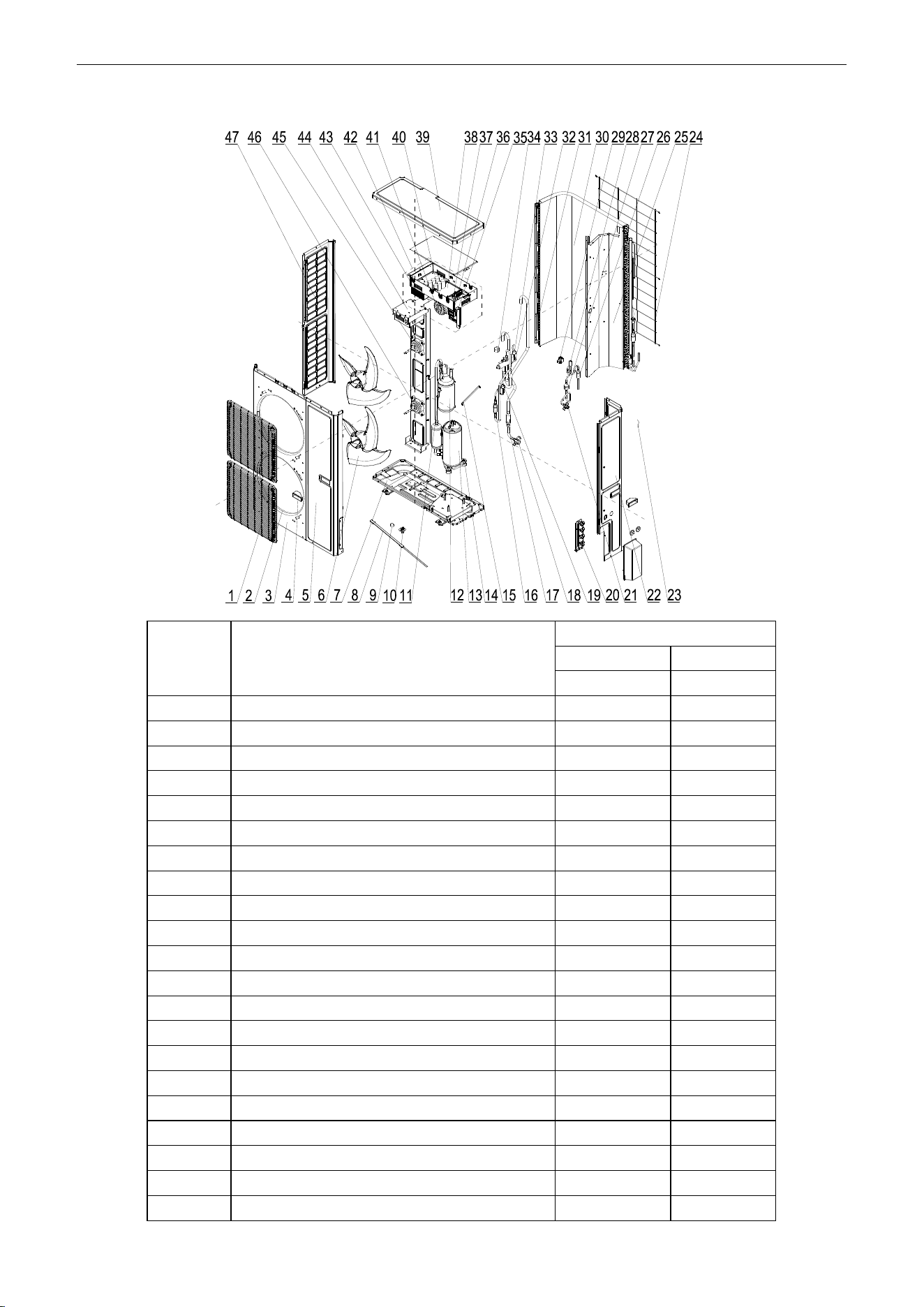
U-Match Series DC Inverter Service Manual
153
Model: UMAT48HP230V1AO Exploded Views and spare parts list:
NO.
Name of Part
UMAT48HP230V1AO
Product Code
CF090W0781
Part Code
Quantity
1
Front Grill
01574100009
2
2
Diversion Circle
10474100001
2
3
Cabinet Assy
01514100006
1
4
Handle
26235253
2
5
Front Side Plate
01314100021P
1
6
Axial Flow Fan
10434100003
2
7
Chassis Sub-assy
01195200020P
1
8
electrical heater
7651521215
1
9
Drainage hole Cap
06813401
3
10
Drainage Connecter
06123401
1
11
Pressure Protect Switch
46020007
1
12
Gas-liquid Separator Sub-Assy
0722501801
1
13
Compressor
00204100001
1
14
Compressor Gasket
76710247
3
15
Wire Clamp
02145008
1
16
Silencer
07245012
2
17
Strainer
07411100014
1
18
Cut off Valve
07133844
1
19
Pressure Protect Switch
46020003
1
20
Valve Support Sub-Assy
01805200204P
1
21
Cut off Valve
07130209
1
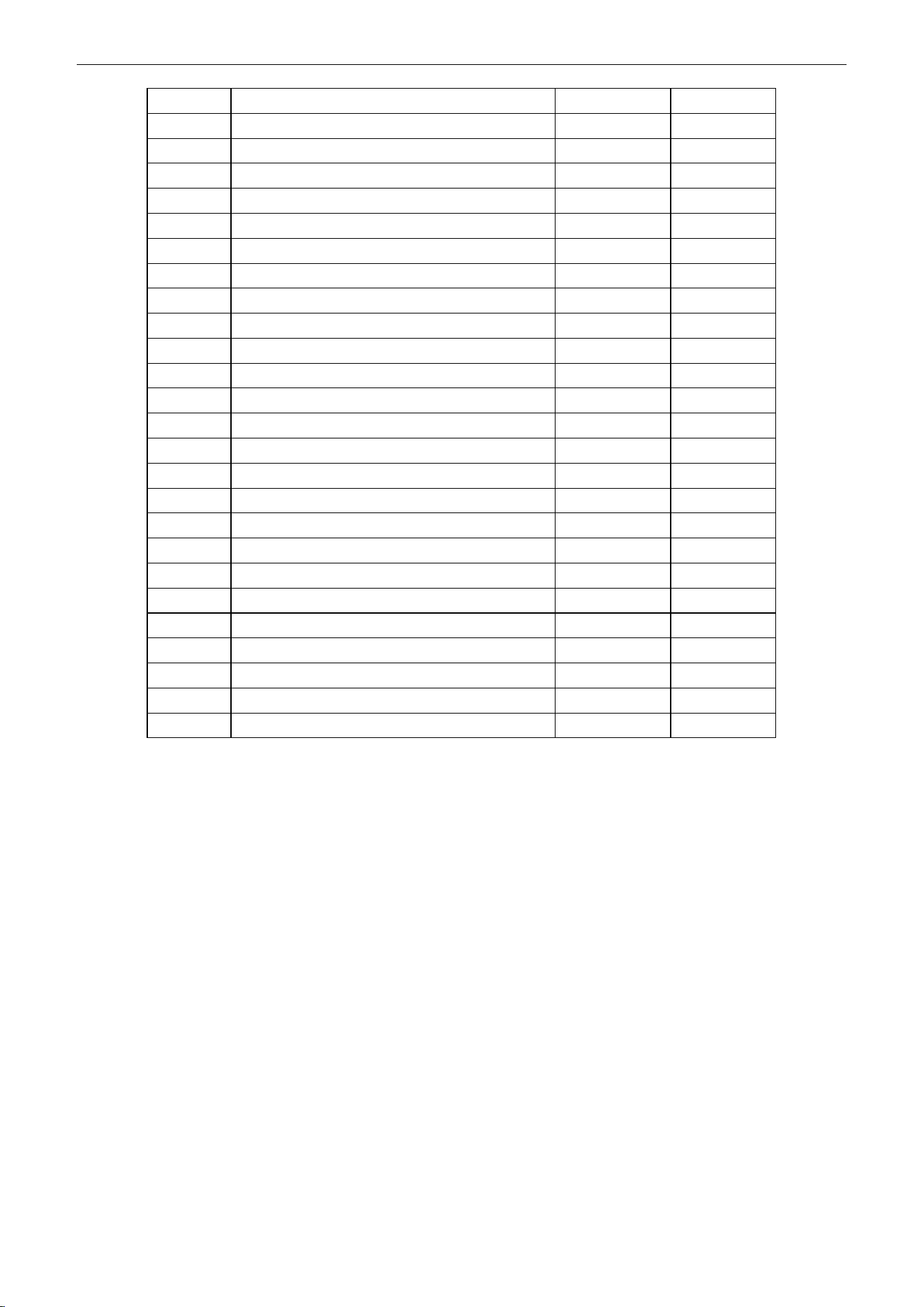
U-Match Series DC Inverter Service Manual
154
22
Rear Side Plate Sub-Assy
01315200088P
1
23
Temperature Sensor
3900028025G
1
24
Rear Grill
01574100004
1
25
Clapboard
01245200007
1
26
Bidirection Strainer
07220016
1
27
Strainer
07415210
1
28
Electronic Expansion Valve
07135176
1
29
Electric Expand Valve Fitting
43000344
1
30
Condenser Assy
1125200197
1
31
Supporting Strip
01894100026
1
32
4-way Valve
43000338
1
33
Pressure Protect Switch
4602000902
1
34
Magnet Coil
4300040032
1
35
Terminal Board
420101852
1
36
Terminal Board
42011242
1
37
Main Board
30224000035
1
38
Filter Board
30228000006
1
39
Coping
01264100008P
1
40
Main Board
30228000005
1
41
PFC Inductance
43128000015
1
42
Electric Box Assy
01395200485
1
43
Radiator
49018000052
1
44
Motor Support Sub-Assy
01805200244
1
45
Fan Motor
15704115
1
46
Fan Motor
1570411501
1
47
Left Side Plate
01314100013P
1
Above data is subject to change without notice, pls reference the SP in global service website.
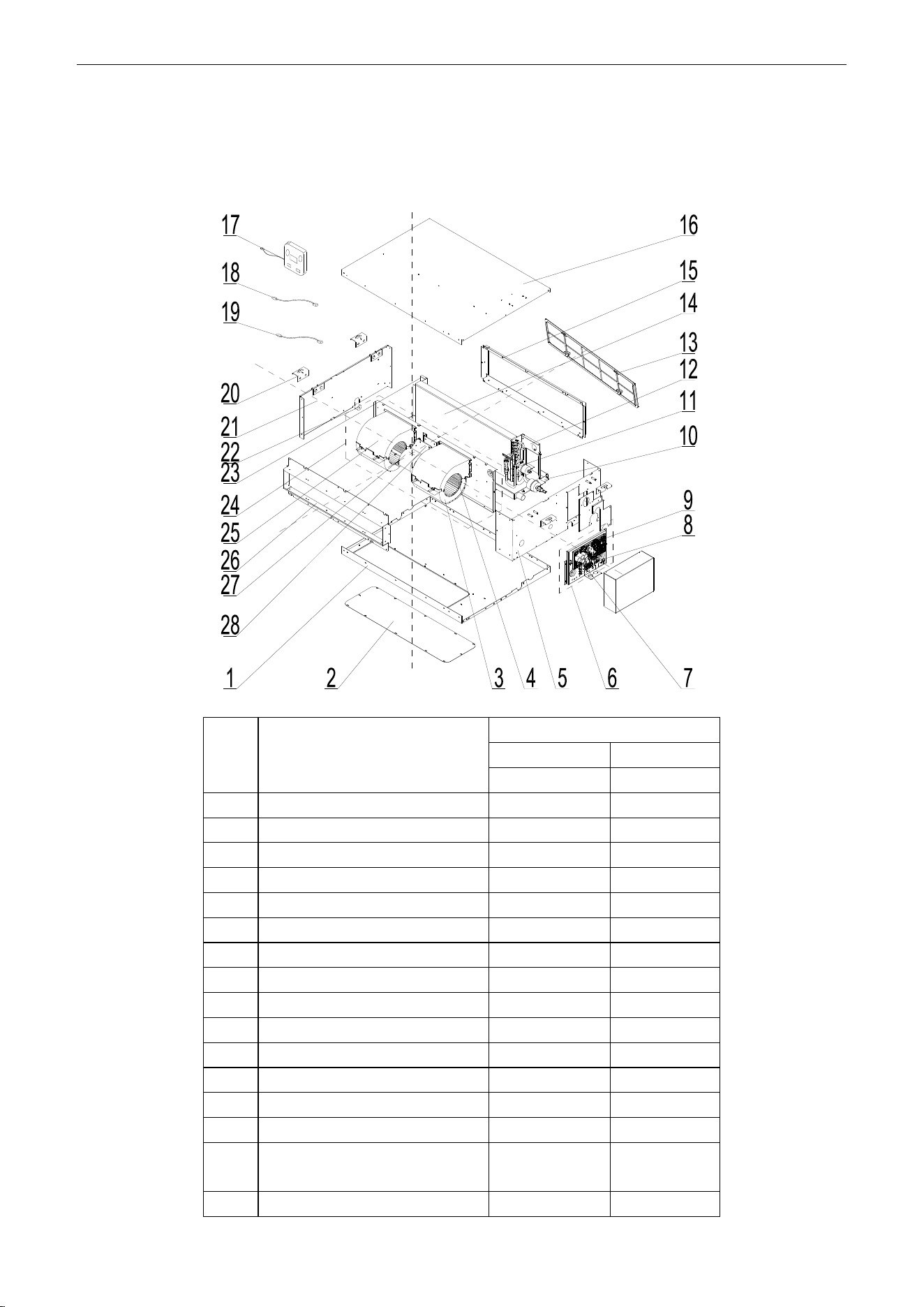
U-Match Series DC Inverter Service Manual
155
5.2 Indoor Unit
5.2.1 Duct Type
Model: UMAT18HP230V1AD exploded view and spare parts list
NO.
Name of Part
UMAT18HP230V1AD
Product Code
CF060N0513
Part Code
Quantity
1
Bottom Cover Plate
01265409
1
2
Cover Of Air-In
01258650
1
3
Propeller Housing
22202029
2
4
Centrifugal fan
10319051
2
5
Left Side Plate Sub-Assy
01315200062
1
6
Electric Box Assy
01395200452
1
7
Terminal Board
42010194
1
8
Terminal Board
4201025301
1
9
Main Board
30224000030
1
10
Water Tray Assy
01285269
1
11
Strainer
07212121
1
12
Left Support of Evaporator
01805200310
1
13
Filter
11725202
1
14
Evaporator Assy
01025394
1
15
side plate sub- assy of return air
frame
02225234
1
16
Top Cover Board Sub-assy
01265200095
1

U-Match Series DC Inverter Service Manual
156
17
Display Board
30294000007
1
18
Ambient Temperature Sensor
3900012123
1
19
Temperature Sensor
390001921G
1
20
Hook
02112446
4
21
Right Side Plate Sub-Assy
01315200077
1
22
Choke Plug of Water Pipe
76712454
1
23
Right Support of Evaporator
01078625
1
24
Centrifugal fan assy
15405200031
1
25
Front Volute Casing
22202030
2
26
Return air frame sub-assy
01498641
1
27
Fan Motor
15704100001
1
28
Supporter
01804100140
1
Above data is subject to change without notice, pls reference the SP in global service website.
U-Match Series DC Inverter Service Manual
157
Model: UMAT18HP230V1AD (with water pump) exploded view and spare parts list
NO.
Name of Part
UMAT18HP230V1AD
Product Code
CF060N0512
Part Code
Quantity
1
Main Board
30224000030
1
2
Terminal Board
42010194
1
3
Terminal Board
4201025301
1
4
Left Side Plate Assy
01315200098
1
5
Water Pump Assy
15405200075
1
6
Water Pump
43138220
1
7
Pump Drainpipe
05235301
1
8
Water Level Switch
45018012
1
9
Cover Of Air-In
01258650
1
10
Bottom Cover Plate
01265409
1
11
Seal Of Left Side Plate Sub-Assy
01494128
1
12
Choke Plug of Water Pipe
76712454
2
13
Seal Of Connection Pipe
01498640
1
14
Water Tray Assy
01284166
1
15
Strainer
07212121
1
16
Left Support of Evaporator
01805200310
1
17
Evaporator Assy
01025394
1
18
Filter
11725202
1
19
side plate sub- assy of return air
frame
02225234
1
20
Right Support of Evaporator
01078625
1
U-Match Series DC Inverter Service Manual
158
21
Right Side Plate Sub-Assy
01315200077
1
22
Ambient Temperature Sensor
3900012123
1
23
Temperature Sensor
390001921G
1
24
Display Board
30294000007
1
25
Top Cover Board Sub-assy
01265200095
1
26
Front Volute Casing
22202030
2
27
Fan Motor
15704100001
1
28
Supporter
01804100140
1
29
Return air frame sub-assy
01498641
1
30
Hook
02112446
4
31
Centrifugal fan assy
15405200031
1
32
Centrifugal fan
10319051
2
33
Propeller Housing
22202029
2
34
Motor Support Sub-Assy
01709056
2
35
Electric Box Assy
01395200452
1
Above data is subject to change without notice, pls reference the SP in global service website.
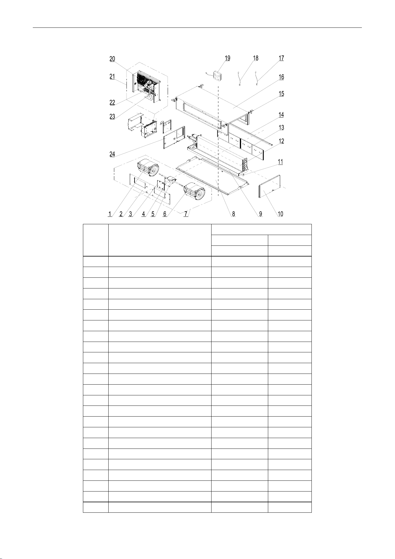
U-Match Series DC Inverter Service Manual
159
Model: UMAT24HP230V1AD exploded view and spare parts list
NO.
Name of Part
UMAT24HP230V1AD
Product Code
CF060N0523
Part Code
Quantity
1
Blower
15012454
1
2
Blower Mounting Plate Sub-Assy
01325200039
1
3
Support Sub-assy
01805200164
1
4
Supporter
01804100140
1
5
Brushless DC Motor
15705200006
1
6
Blower
15012458
1
7
Centrifugal fan assy
15405200029
1
8
Lower Cover Plate Sub-Assy
01265304
1
9
Water Tray Assy
01285317
1
10
Left Side Plate Assy
01314155
1
11
Choke Plug of Drain Pipe
76712455
1
12
Evaporator Assy
01025200050
1
13
Filter Sub-Assy
11125303
2
14
filter guide groove sub-assy
02285301
1
15
Hook
02112446
4
16
Top Cover Board Assy
01265226
1
17
Tube sensor
3900012128
1
18
Ambient Temperature Sensor
3900012123
1
19
Display Board
30294000007
1
20
Main Board
30224000030
1
21
Electric Box Assy
01395200453
1
22
Terminal Board
42010194
1
23
Terminal Board
4201025301
1
24
Right Side Plate Sub-Assy
01315200057
1
Above data is subject to change without notice, pls reference the SP in global service website.
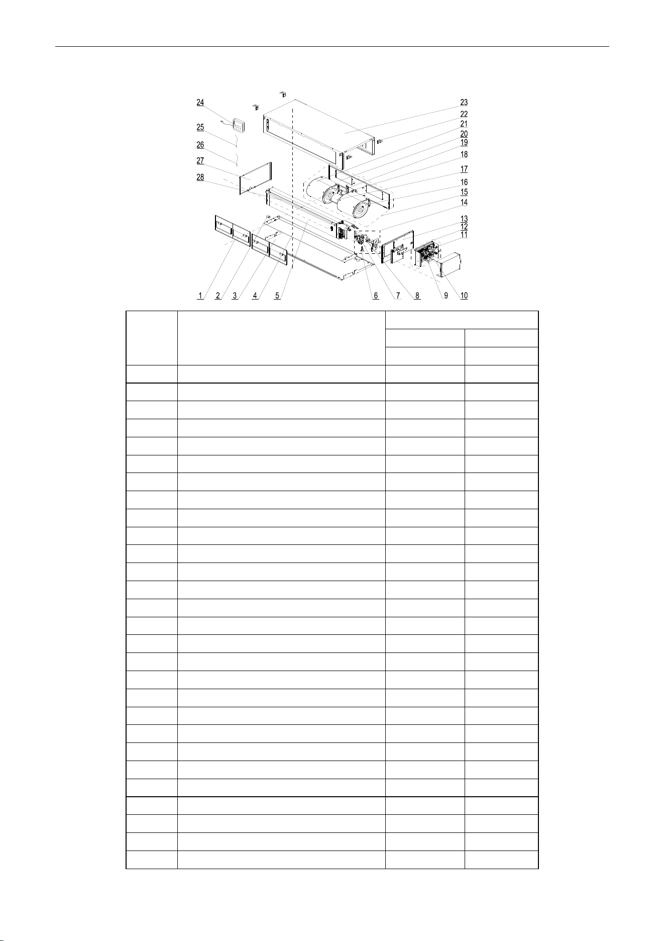
U-Match Series DC Inverter Service Manual
160
Model: UMAT24HP230V1AD (with water pump) exploded view and spare parts list
NO.
Name of Part
UMAT24HP230V1AD
Product Code
CF060N0522
Part Code
Quantity
1
Filter Sub-Assy
11125303
2
2
Choke Plug of Drain Pipe
76712455
2
3
Lower Cover Plate Sub-Assy
01265304
1
4
Water Tray Assy
01285317
1
5
Evaporator Assy
01025200050
1
6
Water Level Switch
450127011
1
7
Water Pump
43138220
1
8
Pump Drainpipe
05235301
1
9
Terminal Board
42010194
1
10
Terminal Board
4201025301
1
11
Main Board
30224000030
1
12
Electric Box Assy
01395200453
1
13
Right Side Plate Sub-Assy
01315200057
1
14
Water Pump Assy
15405392
1
15
Centrifugal fan assy
15405200029
1
16
Blower
15012458
1
17
Brushless DC Motor
15705200006
1
18
Supporter
01804100140
1
19
Support Sub-assy
01805200164
1
20
Blower Mounting Plate Sub-Assy
01325200039
1
21
Blower
15012454
1
22
Hook
02112446
4
23
Top Cover Board Assy
01265226
1
24
Display Board
30294000007
1
25
Ambient Temperature Sensor
3900012123
1
26
Tube sensor
3900012128
1
27
Left Side Plate Assy
01314155
1
28
filter guide groove sub-assy
02285301
1
Above data is subject to change without notice, pls reference the SP in global service website.
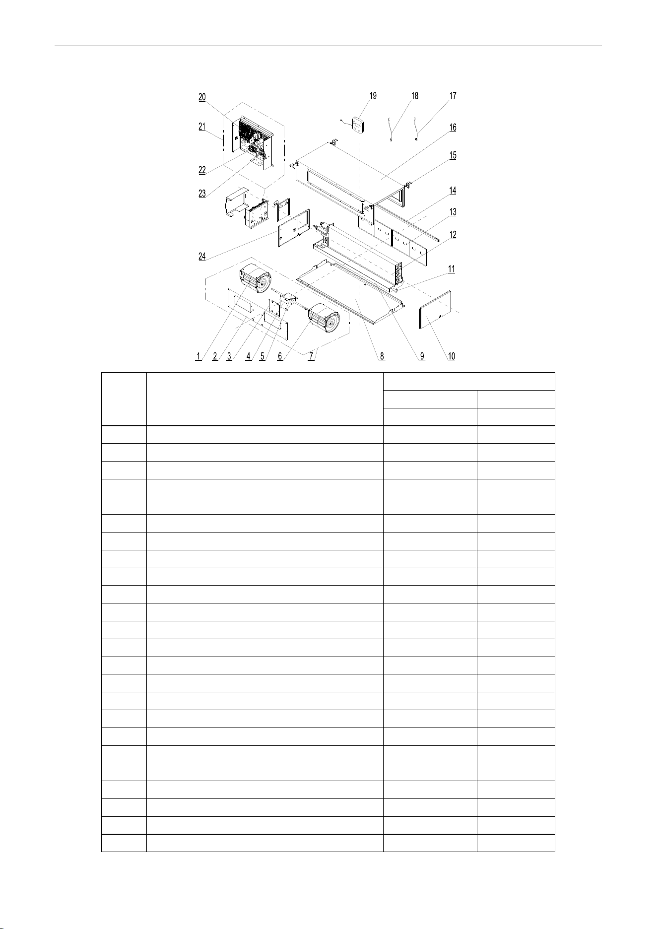
U-Match Series DC Inverter Service Manual
161
Model: UMAT30HP230V1AD exploded view and spare parts list
NO.
Name of Part
UMAT30HP230V1AD
Product Code
CF060N0580
Part Code
Quantity
1
Blower
15012454
1
2
Blower Mounting Plate Sub-Assy
01325200039
1
3
Support Sub-assy
01805200164
1
4
Supporter
01804100140
1
5
Brushless DC Motor
15705200006
1
6
Blower
15012458
1
7
Centrifugal fan assy
15405200029
1
8
Lower Cover Plate Sub-Assy
01265304
1
9
Water Tray Assy
01285317
1
10
Left Side Plate Assy
01314155
1
11
Choke Plug of Drain Pipe
76712455
1
12
Evaporator Assy
01025200050
1
13
Filter Sub-Assy
11125303
2
14
filter guide groove sub-assy
02285301
1
15
Hook
02112446
4
16
Top Cover Board Assy
01265226
1
17
Tube sensor
3900012128
1
18
Ambient Temperature Sensor
3900012123
1
19
Display Board
30294000007
1
20
Main Board
30224000030
1
21
Electric Box Assy
01395200453
1
22
Terminal Board
42010194
1
23
Terminal Board
4201025301
1
24
Right Side Plate Sub-Assy
01315200057
1
Above data is subject to change without notice, pls reference the SP in global service website.
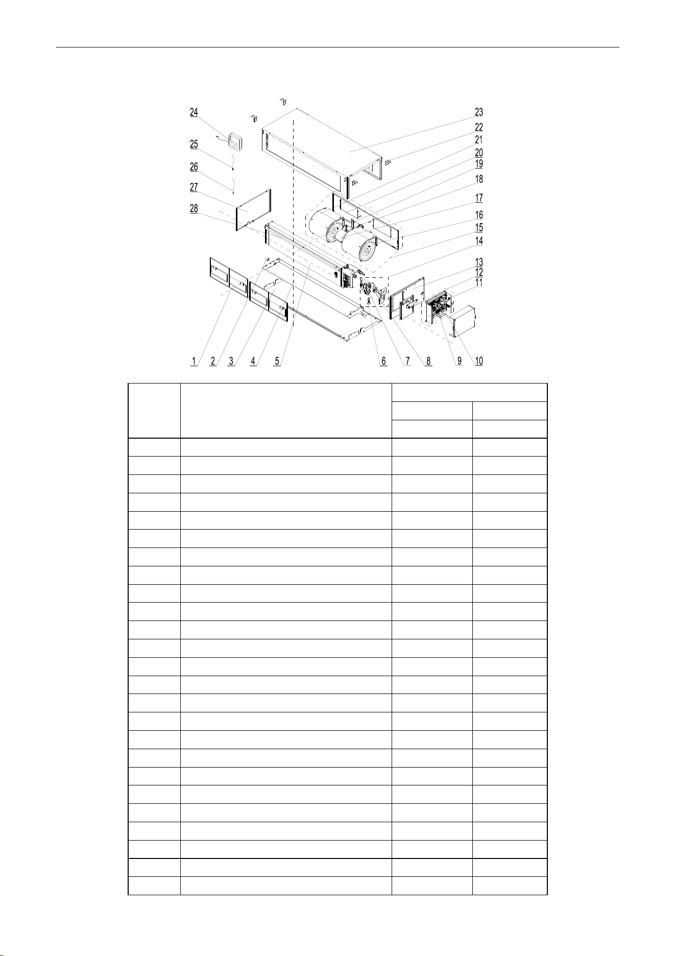
U-Match Series DC Inverter Service Manual
162
Model: UMAT30HP230V1AD (with water pump) exploded view and spare parts list
NO.
Name of Part
UMAT30HP230V1AD
Product Code
CF060N0590
Part Code
Quantity
1
Filter Sub-Assy
11125303
2
2
Choke Plug of Drain Pipe
76712455
2
3
Lower Cover Plate Sub-Assy
01265304
1
4
Water Tray Assy
01285317
1
5
Evaporator Assy
01025200050
1
6
Water Level Switch
450127011
1
7
Water Pump
43138220
1
8
Pump Drainpipe
05235301
1
9
Terminal Board
42010194
1
10
Terminal Board
4201025301
1
11
Main Board
30224000030
1
12
Electric Box Assy
01395200453
1
13
Right Side Plate Sub-Assy
01315200057
1
14
Water Pump Assy
15405392
1
15
Centrifugal fan assy
15405200029
1
16
Blower
15012458
1
17
Brushless DC Motor
15705200006
1
18
Supporter
01804100140
1
19
Support Sub-assy
01805200164
1
20
Blower Mounting Plate Sub-Assy
01325200039
1
21
Blower
15012454
1
22
Hook
02112446
4
23
Top Cover Board Assy
01265226
1
24
Display Board
30294000007
1
25
Ambient Temperature Sensor
3900012123
1
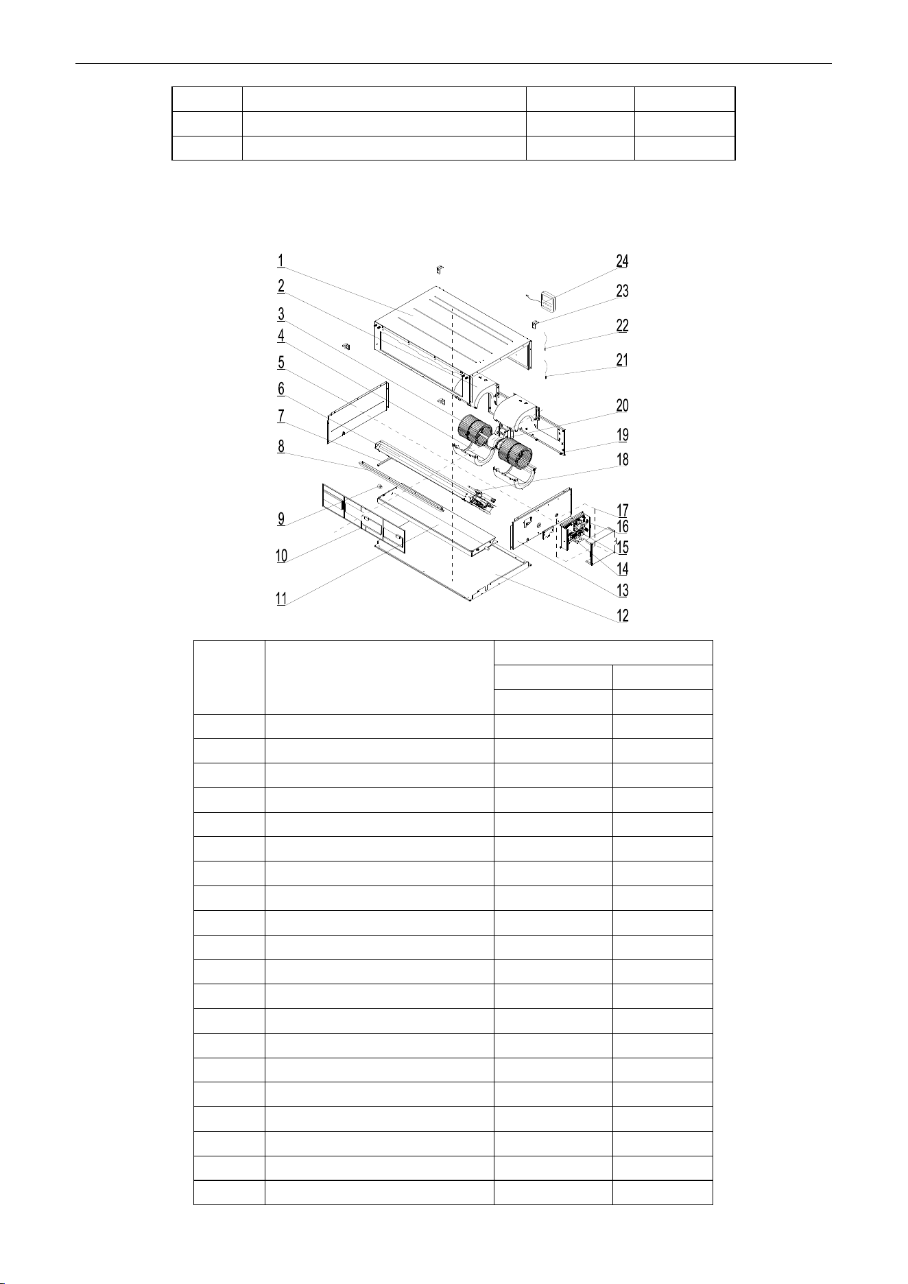
U-Match Series DC Inverter Service Manual
163
26
Tube sensor
3900012128
1
27
Left Side Plate Assy
01314155
1
28
filter guide groove sub-assy
02285301
1
Above data is subject to change without notice, pls reference the SP in global service website.
Model: UMAT36HP230V1AD exploded view and spare parts list
NO.
Name of Part
UMAT36HP230V1AD
Product Code
CF060N0533
Part Code
Quantity
1
Top Cover Board Assy
01265200086
1
2
Propeller Housing(Upper)
26904100051
2
3
Centrifugal Fan
10424100001
2
4
Propeller Housing(Lower)
26904100052
2
5
Left Side Plate Assy
01315306
1
6
Evaporator Assy
01025200052
1
7
Supporting Board of evaporator
018953022
1
8
Side Plate of Air intake
01375301
1
9
Choke Plug of Drain Pipe
76712455
1
10
Filter Sub-Assy
111253031
2
11
Water Tray Assy
01285323
1
12
Lower Cover Plate Sub-Assy
15265301
1
13
Right Side Plate Sub-Assy
01315200061
1
14
Terminal Board
42010194
1
15
Terminal Board
4201025301
1
16
Main Board
30224000030
1
17
Electric Box Assy
01395200453
1
18
Strainer
07220005
1
19
Blower Mounting Plate Sub-Assy
01325200044
1
20
Brushless DC Motor
15709400006
1
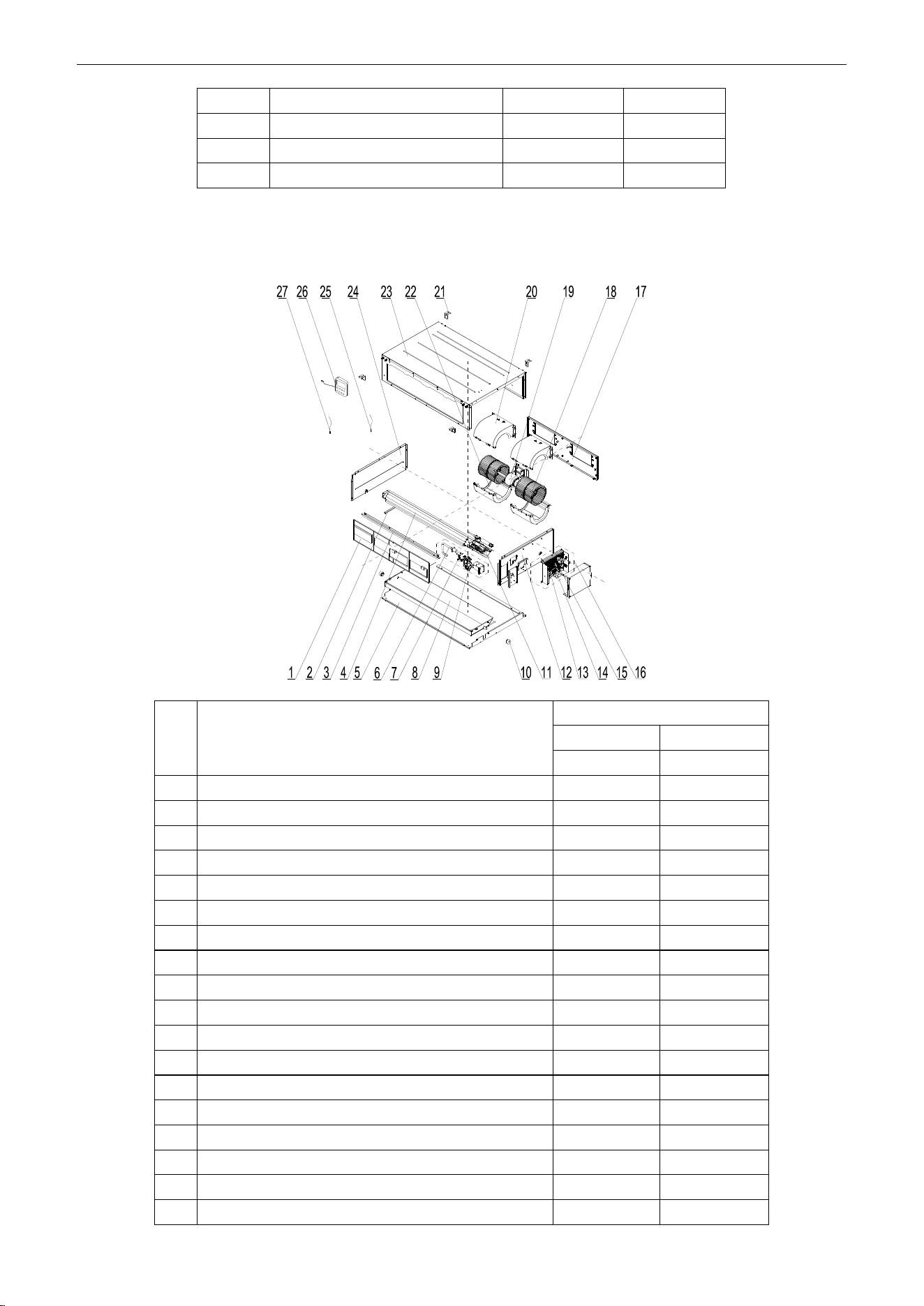
U-Match Series DC Inverter Service Manual
164
21
Ambient Temperature Sensor
3900012123
1
22
Temperature Sensor
390001921G
1
23
Hook
02112466
4
24
Display Board
30294000007
1
Above data is subject to change without notice, pls reference the SP in global service website.
Model: UMAT36HP230V1AD (with water pump) exploded view and spare parts list
NO.
Name of Part
UMAT36HP230V1AD
Product Code
CF060N0532
Part Code
Quantity
1
Filter Sub-Assy
111253031
2
2
Supporting Board of evaporator
018953022
1
3
Side Plate of Air intake
01375301
1
4
Evaporator Assy
01025200052
1
5
Lower Cover Plate Sub-Assy
15265301
1
6
Pump Drainpipe
05235301
1
7
Liquid Level Switch
4501801203
1
8
Water Tray Assy
01285323
1
9
Water Pump
43138220
1
10
Choke Plug of Drain Pipe
76712455
1
11
Strainer
07220005
1
12
Right Side Plate Sub-Assy
01315200100
1
13
Main Board
30224000030
1
14
Terminal Board
42010194
1
15
Terminal Board
4201025301
1
16
Electric Box Assy
01395200453
1
17
Blower Mounting Plate Sub-Assy
01325200044
1
18
Centrifugal Fan
10424100001
2
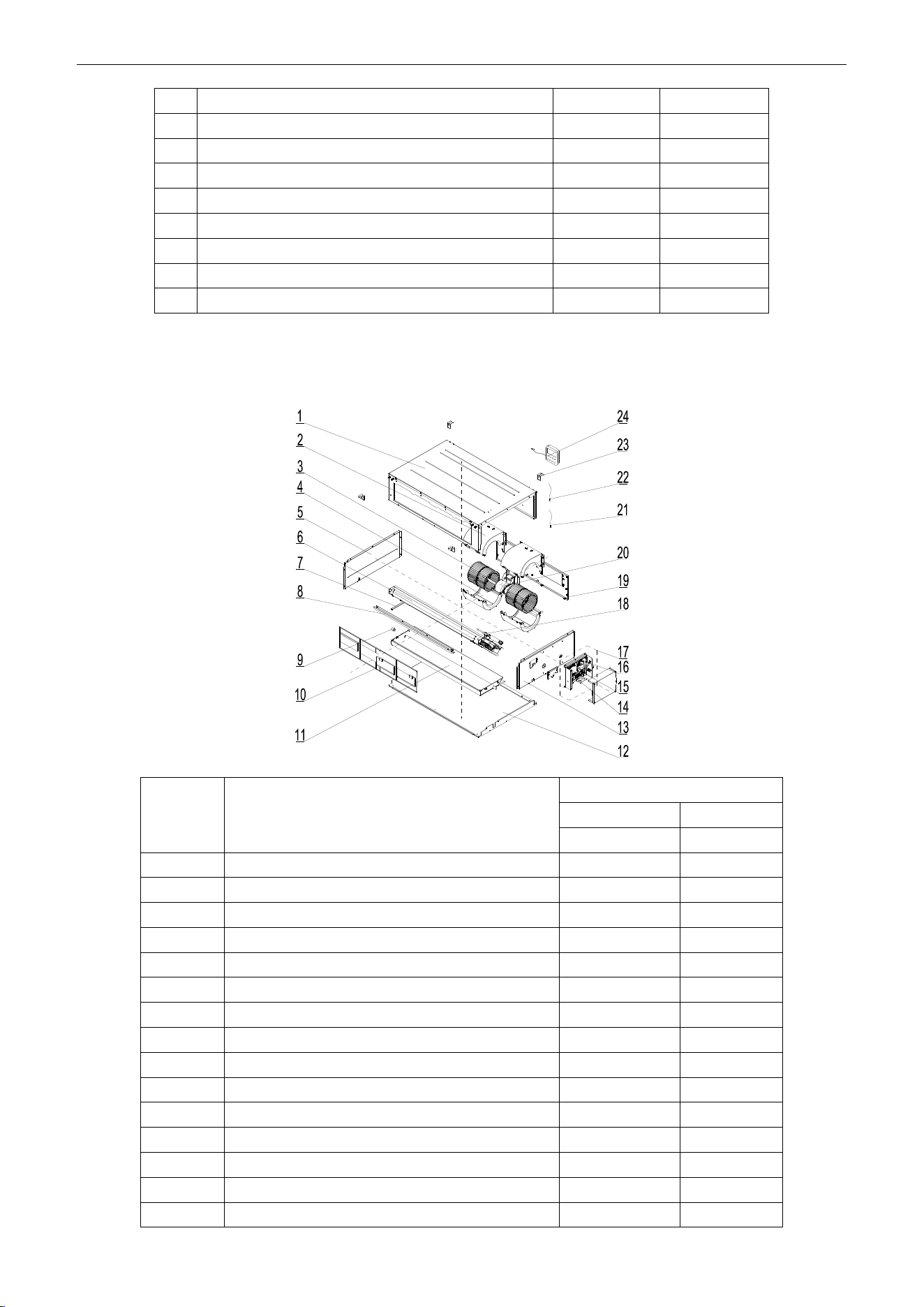
U-Match Series DC Inverter Service Manual
165
19
Brushless DC Motor
15709400006
1
20
Propeller Housing(Upper)
26904100051
2
21
Hook
02112466
4
22
Propeller Housing(Lower)
26904100052
2
23
Top Cover Board Assy
01265200086
1
24
Left Side Plate Assy
01315306
1
25
Temperature Sensor
390001921G
1
26
Display Board
30294000007
1
27
Ambient Temperature Sensor
3900012123
1
Above data is subject to change without notice, pls reference the SP in global service website.
Model: UMAT42HP230V1AD exploded view and spare parts list
NO.
Name of Part
UMAT42HP230V1AD
Product Code
CF060N0600
Part Code
Quantity
1
Top Cover Board Assy
01265200086
1
2
Propeller Housing(Upper)
26904100051
2
3
Centrifugal Fan
10424100001
2
4
Propeller Housing(Lower)
26904100052
2
5
Left Side Plate Assy
01315306
1
6
Evaporator Assy
01025200052
1
7
Supporting Board of evaporator
018953022
1
8
Side Plate of Air intake
01375301
1
9
Choke Plug of Drain Pipe
76712455
1
10
Filter Sub-Assy
111253031
2
11
Water Tray Assy
01285323
1
12
Lower Cover Plate Sub-Assy
15265301
1
13
Right Side Plate Sub-Assy
01315200061
1
14
Terminal Board
42010194
1
15
Terminal Board
4201025301
1
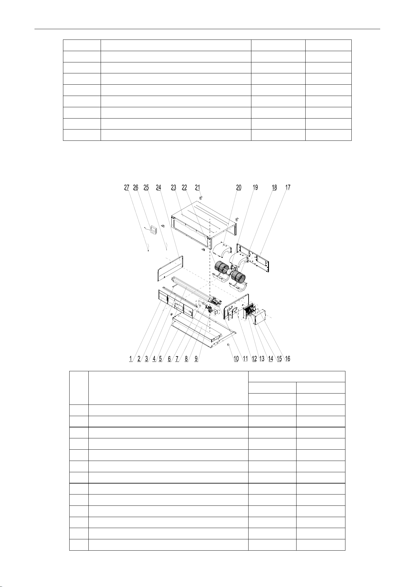
U-Match Series DC Inverter Service Manual
166
16
Main Board
30224000030
1
17
Electric Box Assy
01395200453
1
18
Strainer
07220005
1
19
Blower Mounting Plate Sub-Assy
01325200044
1
20
Brushless DC Motor
15709400006
1
21
Ambient Temperature Sensor
3900012123
1
22
Temperature Sensor
390001921G
1
23
Hook
02112466
4
24
Display Board
30294000007
1
Above data is subject to change without notice, pls reference the SP in global service website.
Model: UMAT42HP230V1AD (with water pump) exploded view and spare parts list
NO.
Name of Part
UMAT42HP230V1AD
Product Code
CF060N0610
Part Code
Quantity
1
Filter Sub-Assy
111253031
2
2
Supporting Board of evaporator
018953022
1
3
Side Plate of Air intake
01375301
1
4
Evaporator Assy
01025200052
1
5
Lower Cover Plate Sub-Assy
15265301
1
6
Pump Drainpipe
05235301
1
7
Liquid Level Switch
4501801203
1
8
Water Tray Assy
01285323
1
9
Water Pump
43138220
1
10
Choke Plug of Drain Pipe
76712455
1
11
Strainer
07220005
1
12
Right Side Plate Sub-Assy
01315200100
1
13
Main Board
30224000030
1
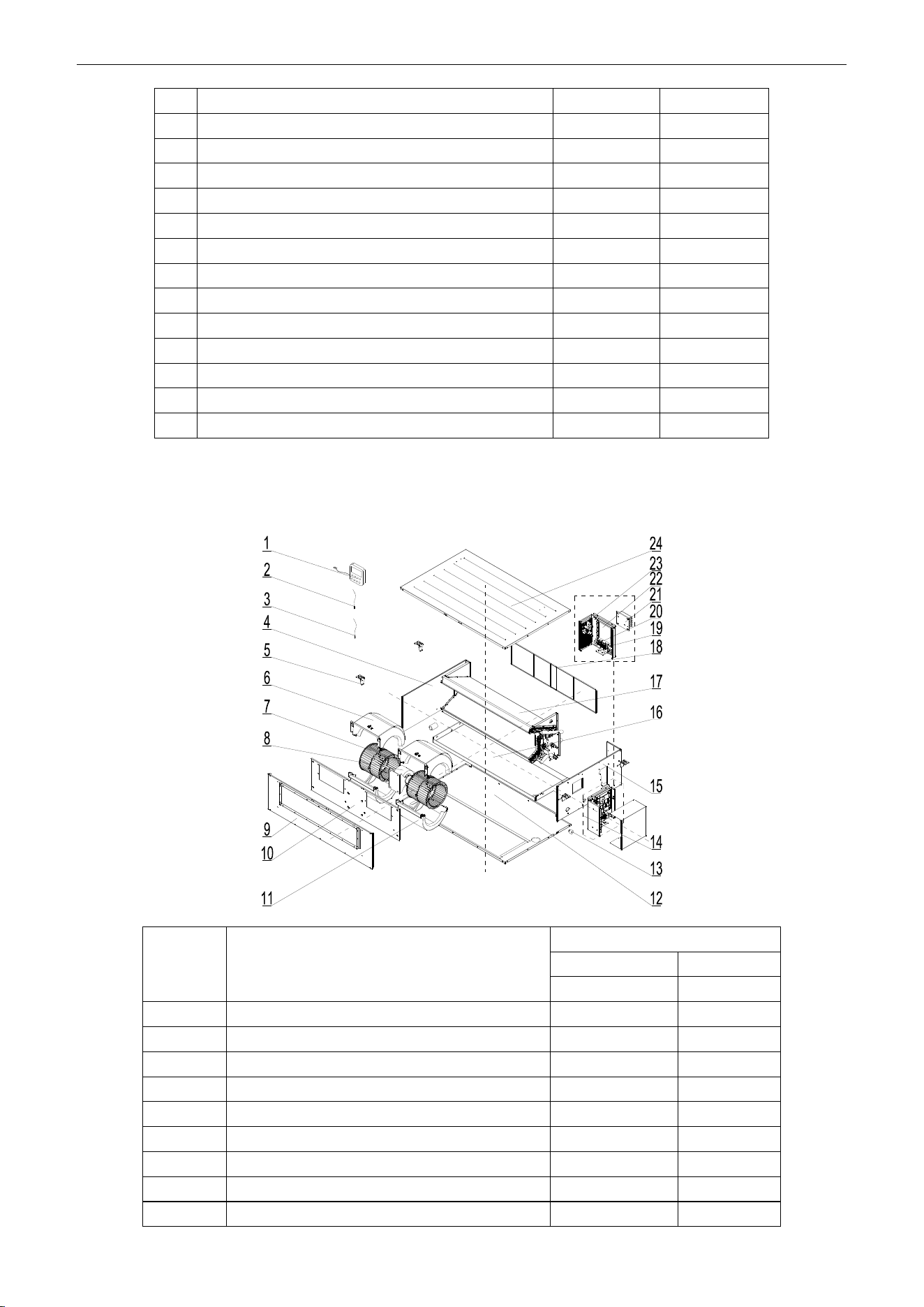
U-Match Series DC Inverter Service Manual
167
14
Terminal Board
42010194
1
15
Terminal Board
4201025301
1
16
Electric Box Assy
01395200453
1
17
Blower Mounting Plate Sub-Assy
01325200044
1
18
Centrifugal Fan
10424100001
2
19
Brushless DC Motor
15709400006
1
20
Propeller Housing(Upper)
26904100051
2
21
Hook
02112466
4
22
Propeller Housing(Lower)
26904100052
2
23
Top Cover Board Assy
01265200086
1
24
Left Side Plate Assy
01315306
1
25
Temperature Sensor
390001921G
1
26
Display Board
30294000007
1
27
Ambient Temperature Sensor
3900012123
1
Above data is subject to change without notice, pls reference the SP in global service website.
Model: UMAT48HP230V1AD exploded view and spare parts list
NO.
Name of Part
UMAT48HP230V1AD
Product Code
CF060N0542
Part Code
Quantity
1
Display Board
30294000007
1
2
Tube sensor
3900012128
1
3
Ambient Temperature Sensor
3900012123
1
4
Left Side Plate Sub-Assy
01315200064
1
5
Hook
02205209
4
6
Propeller Housing(Upper)
26905200010
2
7
Centrifugal Fan
10425200002
2
8
Brushless DC Motor
15709400008
1
9
Front Side Plate Sub-Assy
01315200091
1
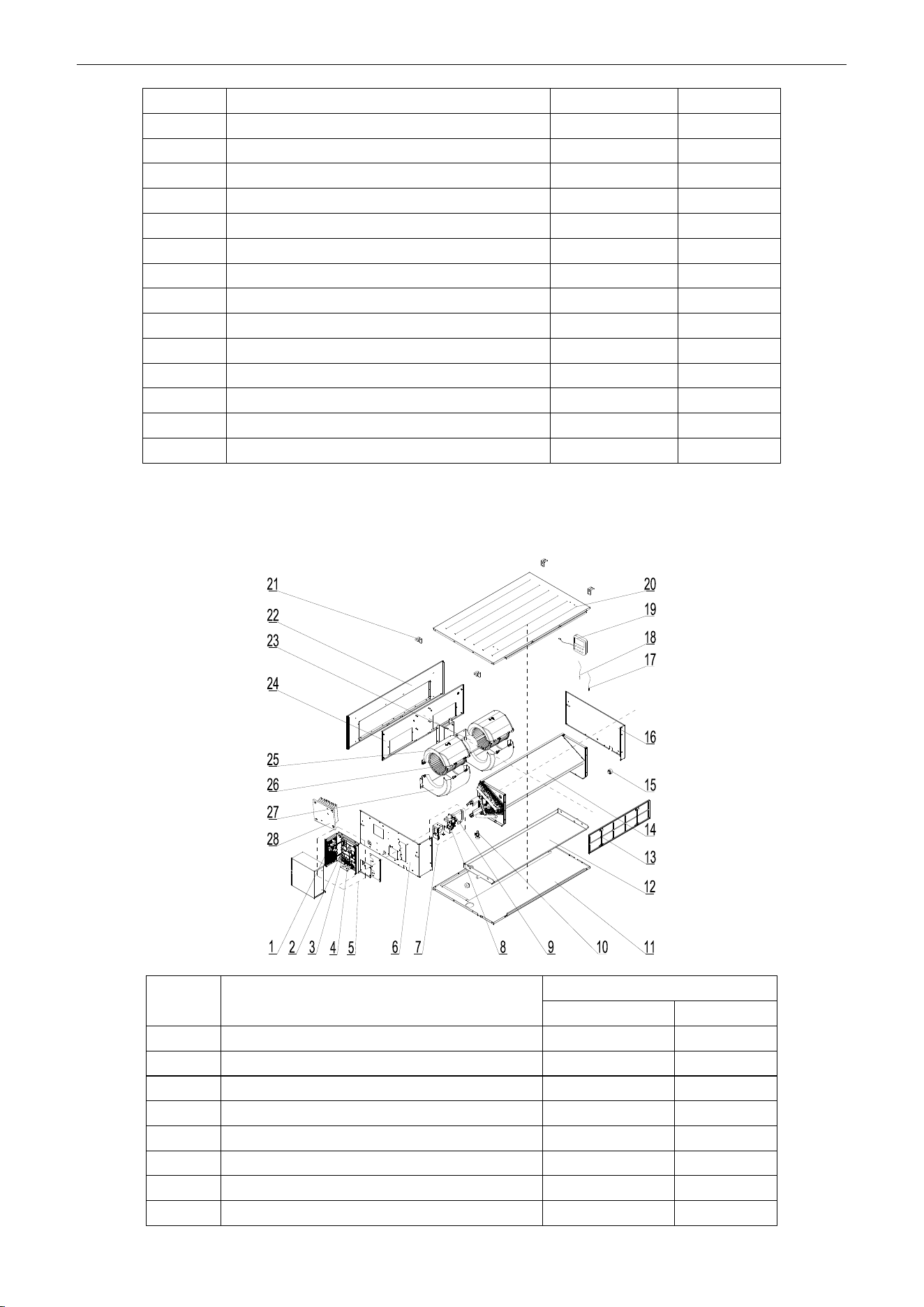
U-Match Series DC Inverter Service Manual
168
10
Blower Mounting Plate Sub-Assy
01325200057
1
11
Propeller Housing(Lower)
26905200011
2
12
Bottom Cover Plate Assy
01265200045
1
13
Choke Plug of Drain Pipe
76712455
1
14
Electric Box Assy
01395200454
1
15
Right Side Plate Assy
0131520006601
1
16
Water Tray Assy
01285200025
1
17
Evaporator Assy
01025200055
1
18
Filter Sub-Assy
111253036
2
19
Terminal Board
42010194
1
20
Terminal Board
4201025301
1
21
Radiator
49018000068
1
22
Main Board
30221000011
1
23
Main Board
30224000039
1
24
Top Cover Board Assy
01265200081
1
Above data is subject to change without notice, pls reference the SP in global service website.
Model: UMAT48HP230V1AD (with water pump) exploded view and spare parts list
NO.
Name of Part
UMAT48HP230V1AD
Product Code
CF060N0543
1
Main Board
30224000039
1
2
Main Board
30221000011
1
3
Terminal Board
4201025301
1
4
Terminal Board
42010194
1
5
Electric Box Assy
01395200471
1
6
Right Side Plate Sub-Assy
01315200078
1
7
Water Pump Assy
15405200081
1
8
Water Pump
4313822001
1
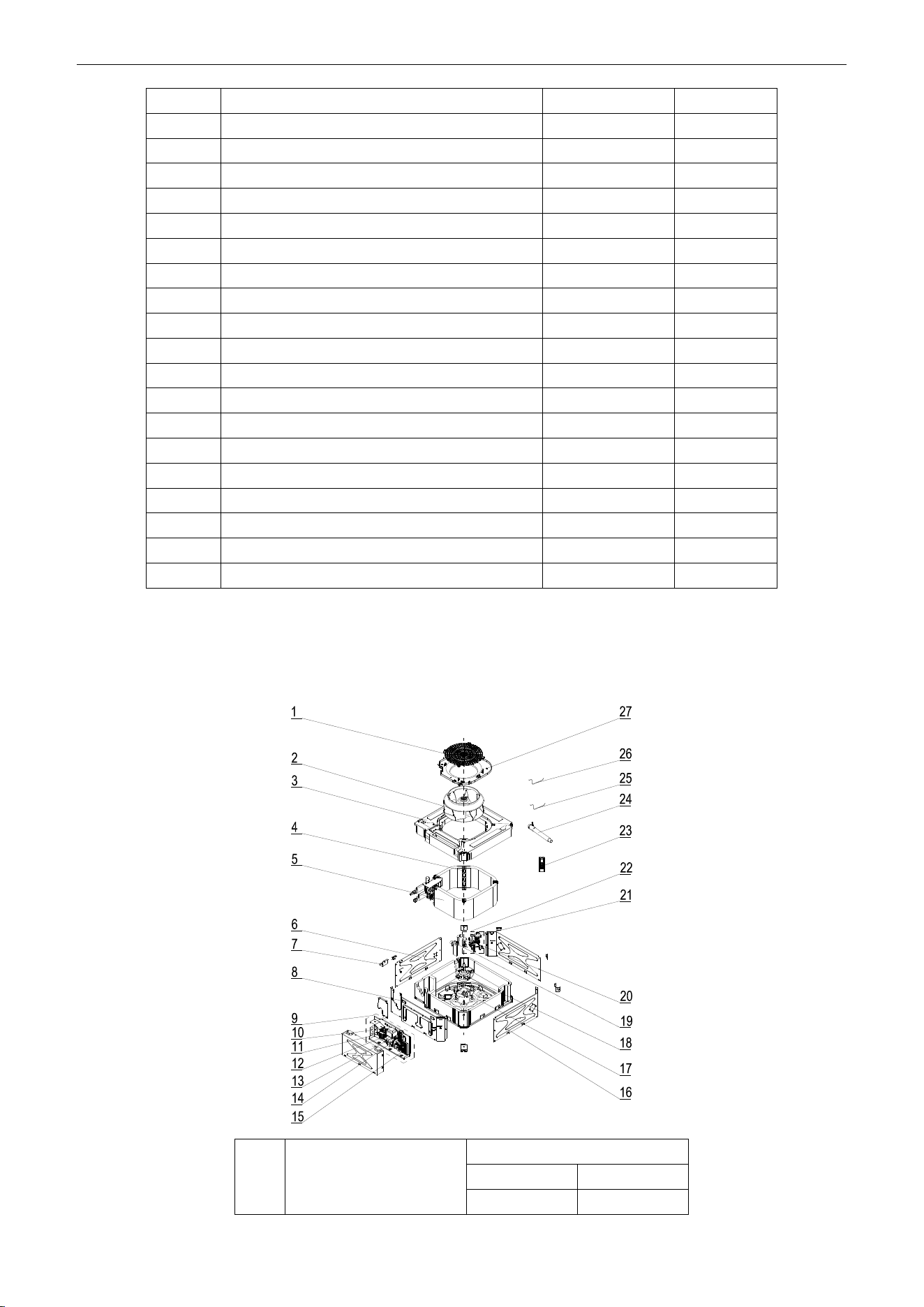
U-Match Series DC Inverter Service Manual
169
9
Pump Drainpipe
05235301
1
10
Water Level Switch
4501270301
1
11
Bottom Cover Plate Assy
01265200045
1
12
Water Tray Assy
01285200025
1
13
Filter Sub-Assy
111253036
2
14
Evaporator Assy
01025200054
1
15
Choke Plug of Drain Pipe
76712455
2
16
Left Side Plate Sub-Assy
01315200064
1
17
Ambient Temperature Sensor
3900012123
1
18
Tube sensor
3900012128
1
19
Display Board
30294000007
1
20
Top Cover Board Assy
01265200081
1
21
Hook
02205209
4
22
Front Side Plate Sub-Assy
01315200091
1
23
Brushless DC Motor
15709400008
1
24
Blower Mounting Plate Sub-Assy
01325200057
1
25
Propeller Housing(Upper)
26905200010
2
26
Centrifugal Fan
10425200002
2
27
Propeller Housing(Lower)
26905200011
2
28
Radiator
49018000068
1
Above data is subject to change without notice, pls reference the SP in global service website.
5.2.2 Cassette Type
Model: UMAT18HP230V1AC exploded view and spare parts list.
NO.
Name of Part
UMAT18HP230V1AC
Product Code
ET010N0801
Part Code
Quantity
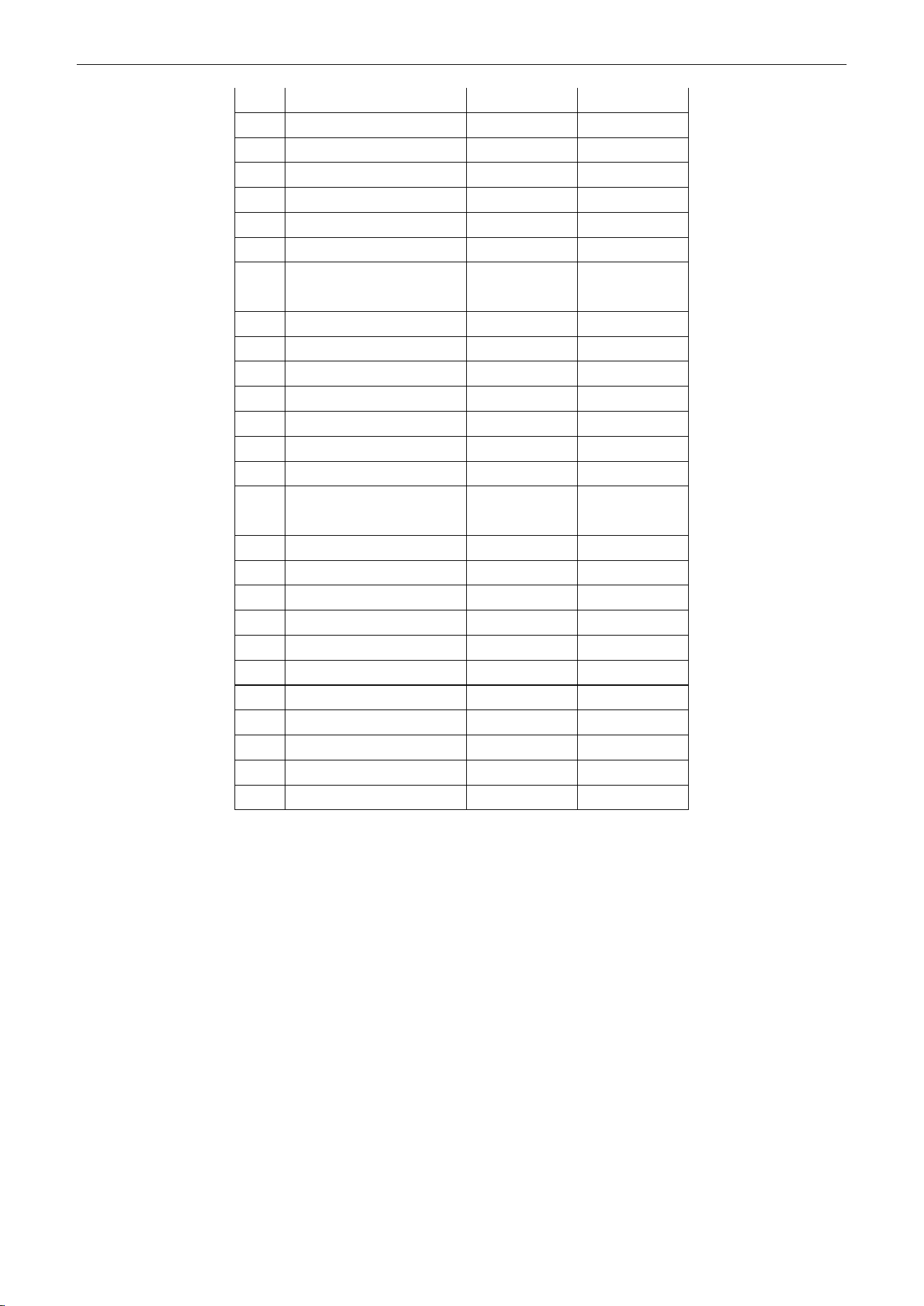
U-Match Series DC Inverter Service Manual
170
1
Rear Grill
26909400007
1
2
Centrifugal Fan
10429400001
1
3
Water Tray Assy
01289400004
1
4
Supporter
01809400007
3
5
Evaporator Assy
01029400013
1
6
Left Side Plate Sub-Assy
01319400012
1
7
Body Installing Support
01332705
4
8
Front Side Plate
Sub-Assy
01319400014
1
9
Electric Box Assy
01399400114
1
10
Terminal Board
4201025301
1
11
Transformer
43110286
1
12
Terminal Board
42010274
1
13
Terminal Board
42011147
1
14
Terminal Board
42011103
2
15
Main Board
30224000028
1
16
Right Side Plate
Sub-Assy
01319400013
2
17
Base Plate Assy
02229400007
1
18
Brushless DC Motor
15709400004
1
19
Pump Drainpipe
04269400001
1
20
Liquid Level Switch
450102013
1
21
Water Pump
43138000024
1
22
Water Pump Assy
15409400003
1
23
Remote Controller
30510516
1
24
Drain Hose Sub-Assy
05232050
1
25
Tube sensor
3900012128
1
26
Room Sensor
39000191
1
27
Diversion Circle
10479400001
1
Above data is subject to change without notice, pls reference the SP in global service website.
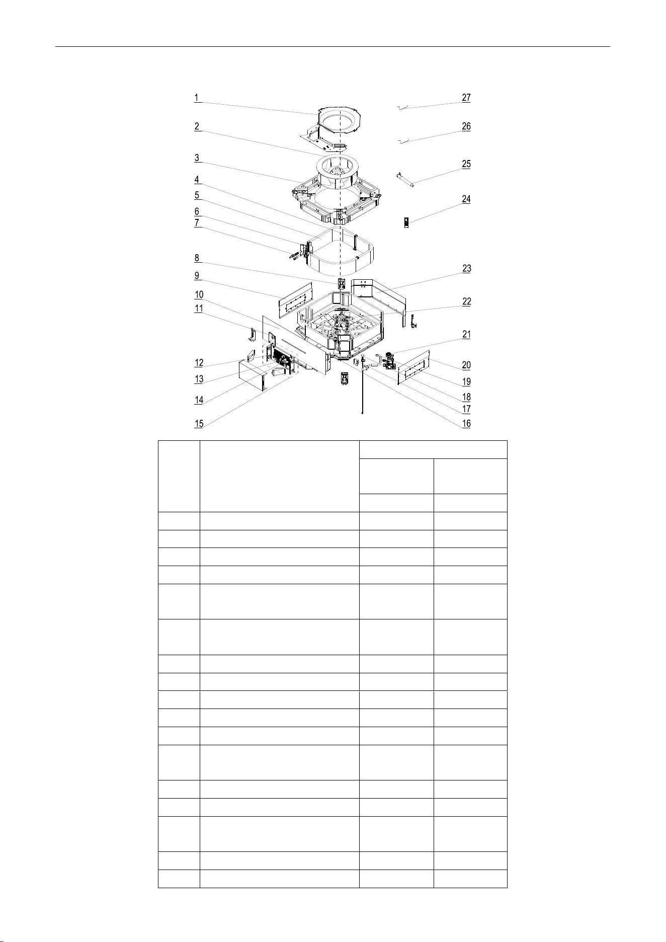
U-Match Series DC Inverter Service Manual
171
Model: UMAT24HP230V1AC exploded view and spare parts list.
NO.
Name of Part
UMAT24HP230V1AC
Product
Code
ET010N0811
Part Code
Quantity
1
Diversion Circle
10372701
1
2
Centrifugal Fan
10312705
1
3
Water Tray Assy
20182701
1
4
Evaporator Support Assy
01072703
2
5
Evaporator Assy
0102940004
5
1
6
Connected Board Assy of
Evaporator
01074042
1
7
Strainer
07212403
1
8
Body Installing Plate
01332701
4
9
Left Side Plate Assy
01302715
1
10
Front Side Plate assy
01302718
1
11
Tube Exit Plate Assy
01382715
1
12
Main Board
3022400002
8
1
13
Terminal Board
4201025301
1
14
Terminal Board
42011222
1
15
Electric Box Assy
0139940012
4
1
16
Base Plate Assy
01222701
1
17
Pump Cover Board Assy
01252713
1

U-Match Series DC Inverter Service Manual
172
18
Water Level Switch
45018012
1
19
Pump Drainpipe
05230026
1
20
Right Side Plate Assy
01302716
1
21
Water Pump
43130324
1
22
Brushless DC Motor
1570940000
4
1
23
Rear Side Plate Assy
01302714
1
24
Remote Controller
30510516
1
25
Drain Hose Sub-Assy
05232702
1
26
Temperature Sensor
390001921G
1
27
Room Sensor
390001912
1
Above data is subject to change without notice, pls reference the SP in global service website.
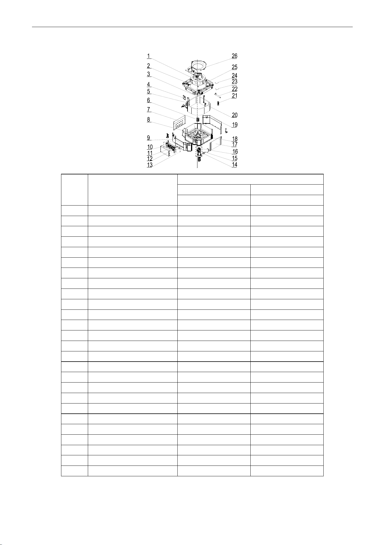
U-Match Series DC Inverter Service Manual
173
Model: UMAT30HP230V1AC exploded view and spare parts list.
NO.
Name of Part
UMAT30HP230V1AC
Product Code
ET010N0840
Part Code
Quantity
1
Centrifugal Fan
10310101
1
2
Water Tray Assy
20182701
1
3
Evaporator Assy
01029400042
1
4
Tube Exit Plate Assy
01382715
1
5
Connection Sheet Assy
01349400007
1
6
Body Installing Plate
01332701
4
7
Left Side Plate Assy
01302711
1
8
Base Plate Assy
01222701
1
9
Front Side Plate assy
0130271301
1
10
Terminal Board
42011222
1
11
Main Board
30224000028
1
12
Terminal Board
4201025301
1
13
Electric Box Assy
01399400128
1
14
Pump Drainpipe
05230026
1
15
Water Level Switch
45018012
1
16
Water Pump
43130324
1
17
Right Side Plate Assy
01302712
1
18
Brushless DC Motor
15709400003
1
19
Rear Side Plate Assy
01302709
1
20
Evaporator Support Assy
01072707
2
21
Remote Controller
30510516
1
22
Drain Hose Sub-Assy
05232702
1
23
Room Sensor
3900012123
1
24
Temperature Sensor
390001921G
1
25
Fan Fixer
10312701
1
26
Diversion Circle
10372722
1
Above data is subject to change without notice, pls reference the SP in global service website.

U-Match Series DC Inverter Service Manual
174
Model: UMAT36HP230V1AC exploded view and spare parts list.
NO.
Name of Part
UMAT36HP230V1AC
Product Code
ET010N0821
Part Code
Quantity
1
Centrifugal Fan
10310101
1
2
Water Tray Assy
20182701
1
3
Evaporator Assy
01029400042
1
4
Tube Exit Plate Assy
01382715
1
5
Connection Sheet Assy
01349400007
1
6
Body Installing Plate
01332701
4
7
Left Side Plate Assy
01302711
1
8
Base Plate Assy
01222701
1
9
Front Side Plate assy
0130271301
1
10
Terminal Board
42011222
1
11
Main Board
30224000028
1
12
Terminal Board
4201025301
1
13
Electric Box Assy
01399400128
1
14
Pump Drainpipe
05230026
1
15
Water Level Switch
45018012
1
16
Water Pump
43130324
1
17
Right Side Plate Assy
01302712
1
18
Brushless DC Motor
15709400003
1
19
Rear Side Plate Assy
01302709
1
20
Evaporator Support Assy
01072707
2
21
Remote Controller
30510516
1
22
Drain Hose Sub-Assy
05232702
1
23
Room Sensor
3900012123
1
24
Temperature Sensor
390001921G
1
25
Fan Fixer
10312701
1
26
Diversion Circle
10372722
1
Above data is subject to change without notice, pls reference the SP in global service website.

U-Match Series DC Inverter Service Manual
175
Model: UMAT42HP230V1AC exploded view and spare parts list.
NO.
Name of Part
UMAT42HP230V1AC
Product Code
ET010N0850
Part Code
Quantity
1
Centrifugal Fan
10310101
1
2
Water Tray Assy
20182701
1
3
Evaporator Assy
01029400042
1
4
Tube Exit Plate Assy
01382715
1
5
Connection Sheet Assy
01349400007
1
6
Body Installing Plate
01332701
4
7
Left Side Plate Assy
01302711
1
8
Base Plate Assy
01222701
1
9
Front Side Plate assy
0130271301
1
10
Terminal Board
42011222
1
11
Main Board
30224000028
1
12
Terminal Board
4201025301
1
13
Electric Box Assy
01399400128
1
14
Pump Drainpipe
05230026
1
15
Water Level Switch
45018012
1
16
Water Pump
43130324
1
17
Right Side Plate Assy
01302712
1
18
Brushless DC Motor
15709400003
1
19
Rear Side Plate Assy
01302709
1
20
Evaporator Support Assy
01072707
2
21
Remote Controller
30510516
1
22
Drain Hose Sub-Assy
05232702
1
23
Room Sensor
3900012123
1
24
Temperature Sensor
390001921G
1
25
Fan Fixer
10312701
1
26
Diversion Circle
10372722
1
Above data is subject to change without notice, pls reference the SP in global service website.
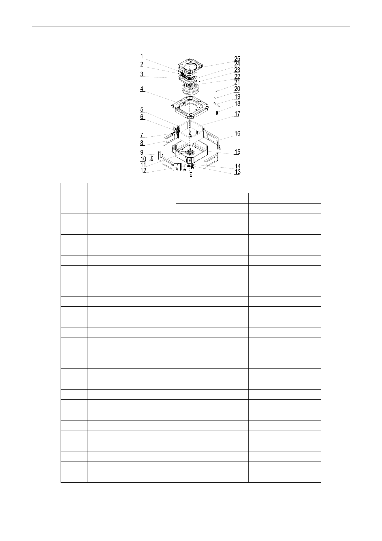
U-Match Series DC Inverter Service Manual
176
Model: UMAT48HP230V1AC exploded view and spare parts list.
NO.
Name of Part
UMAT48HP230V1AC
Product Code
ET010N0831
Part Code
Quantity
1
Terminal Board
4201025801
1
2
Terminal Board
4201025301
1
3
Main Board
30224000028
1
4
Water Tray Assy
01289400002
1
5
Connection Sheet Sub-Assy
01349400002
1
6
Tube Exit Plate Sub-assy
01344100075/01344100
076
1
7
Strainer
07212403
1
8
Right and Left Side Plate
01319448
2
9
Front Side Plate
01319447
1
10
Body Installing Plate
01329420
4
11
Brushless DC Motor
15709400002
1
12
Drainage Hose
05339401
1
13
Water Level Switch
4501801201
1
14
Water Pump
4313822001
1
15
Seat Board Sub-Assy
02229400001
1
16
Rear Side Plate
01319446
1
17
Evaporator Assy
01029400054
1
18
Remote Controller
30510516
1
19
Drain Hose Sub-Assy
05232702
1
20
Room Sensor
390001912
1
21
Temperature Sensor
390001921G
1
22
Centrifugal Fan
10429401
1
23
Fan Fixer
10312701
1
24
Electric Box Assy
01399400128
1
25
Diversion Circle
10479401
1
Above data is subject to change without notice, pls reference the SP in global service website.
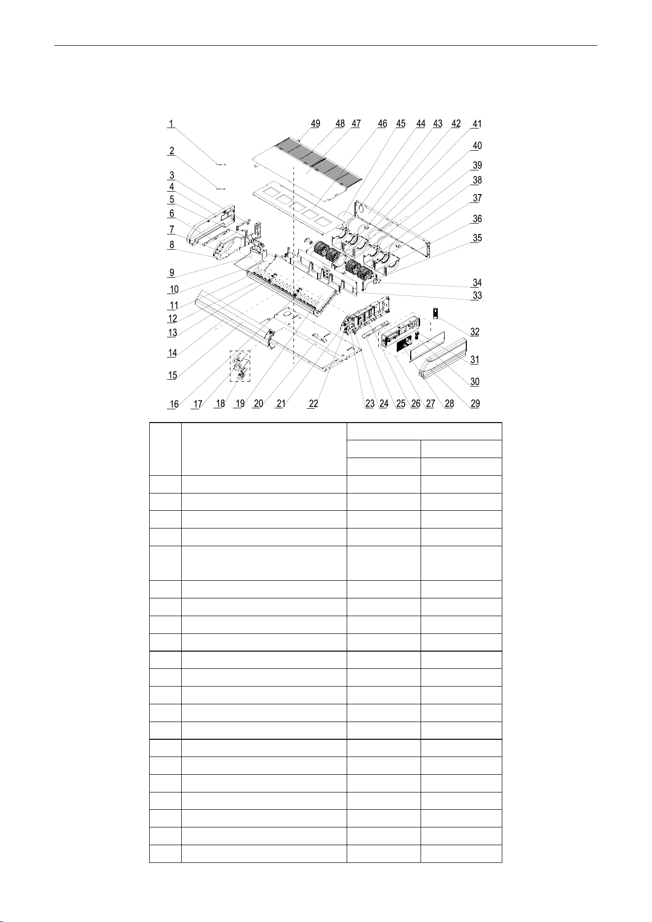
U-Match Series DC Inverter Service Manual
177
5.2.3 Floor Ceiling Type
Model: UMAT18HP230V1AF exploded view and spare parts list.
NO.
Name of Part
UMAT18HP230V1AF
Product Code
ED020N1081
Part Code
Quantity
1
Temperature Sensor
390001923
1
2
Room Sensor
39000191
1
3
Connection Board
02229406
1
4
Right Cover Plate
26909444
1
5
Plate Board of Water Releasing
Flume
26909442
1
6
Installation Supporting Frame
01809402
1
7
Axile Bush
10542704
2
8
Right Side Plate Sub-Assy
01319429
1
9
Water Releasing Flume
26909450
1
10
Connected Board (Evaporator)
01349421
1
11
Air Louver
10619404
16
12
Guide Louver Supporter Sub-assy
0180941601
1
13
Rotating Shaft
26909430
4
14
Front Connection Board
01349414P
1
15
Guide Louver
10619403
2
16
Supporter
26909449
2
17
Fixed Mount
26909426R
1
18
Display Board
30294000009
1
19
Evaporator Assy
01029468
1
20
Rear Side Plate Assy
01319400008
1
21
Rotating Shaft
26909413
1
U-Match Series DC Inverter Service Manual
178
22
Connecting Rod
26909411
1
23
Rotating Shaft
26909412
1
24
Stepping Motor
1521240206
1
25
Installation Supporting Frame
01809401
1
26
Left Side Plate Sub-Assy
0131942801
1
27
Electric Box Assy
01399400113
1
28
Main Board
30224000029
1
29
Left Cover Plate
2690944302
1
30
Terminal Board
42010178
1
31
Terminal Board
4201025301
1
32
Remote Controller
30510516
1
33
Mid-clapboard sub-assy
01249416
1
34
Support Of Motor Bearing
01792408
2
35
O-Gasket of Bearing
76512404
2
36
Rotary Axis Sub-Assy
73018000037
2
37
Centrifugal fan
10425200
4
38
Joint Slack
73018731
2
39
Supporter
01809400024
1
40
Bar Clasp sub-assy
70818000033
1
41
Fan Motor
15704100001
1
42
Supporter
01809400023
1
43
Rear Connection board
01349422
1
44
Front Volute Casing
26905205
4
45
Rear Volute Casing
26905206
4
46
Water Tray Assy
01289404
1
47
Top Cover Board Sub-assy
01269409
1
48
Front Grill sub-assy
01579403
2
49
Drainage Pipe Sub-assy
05235434
1
Above data is subject to change without notice, pls reference the SP in global service website.
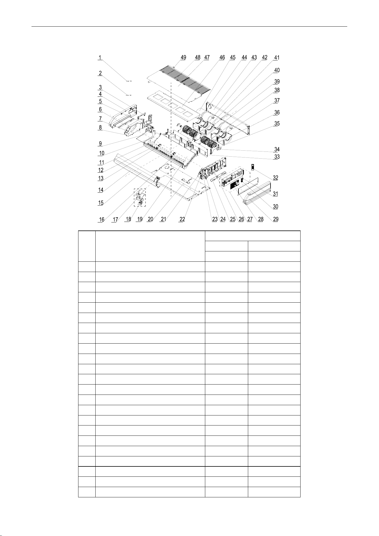
U-Match Series DC Inverter Service Manual
179
Model: UMAT24HP230V1AF Exploded Views and spare parts list:
NO.
Name of Part
UMAT24HP230V1AF
Product Code
ED020N1091
Part Code
Quantity
1
Temperature Sensor
390001923
1
2
Room Sensor
39000191
1
3
Connection Board
02229406
1
4
Right Cover Plate
26909444
1
5
Plate Board of Water Releasing Flume
26909442
1
6
Installation Supporting Frame
01809402
1
7
Axile Bush
10542704
2
8
Right Side Plate Sub-Assy
01319429
1
9
Water Releasing Flume
26909450
1
10
Connected Board (Evaporator)
01349421
1
11
Air Louver
10619404
16
12
Guide Louver Supporter Sub-assy
0180941601
1
13
Rotating Shaft
26909430
4
14
Front Connection Board
01349414P
1
15
Guide Louver
10619403
2
16
Supporter
26909449
2
17
Fixed Mount
26909426R
1
18
Display Board
30294000009
1
19
Evaporator Assy
01029400046
1
20
Rear Side Plate Assy
01319400008
1
21
Rotating Shaft
26909413
1
22
Connecting Rod
26909411
1
23
Rotating Shaft
26909412
1
U-Match Series DC Inverter Service Manual
180
24
Stepping Motor
1521240206
1
25
Installation Supporting Frame
01809401
1
26
Left Side Plate Sub-Assy
0131942801
1
27
Electric Box Assy
01399400113
1
28
Main Board
30224000029
1
29
Left Cover Plate
2690944302
1
30
Terminal Board
42010178
1
31
Terminal Board
4201025301
1
32
Remote Controller
30510516
1
33
Mid-clapboard sub-assy
01249416
1
34
Support Of Motor Bearing
01792408
2
35
O-Gasket of Bearing
76512404
2
36
Rotary Axis Sub-Assy
73018000037
2
37
Centrifugal fan
10425200
4
38
Joint Slack
73018731
2
39
Supporter
01809400024
1
40
Bar Clasp sub-assy
70818000033
1
41
Fan Motor
15704100001
1
42
Supporter
01809400023
1
43
Rear Connection board
01349422
1
44
Front Volute Casing
26905205
4
45
Rear Volute Casing
26905206
4
46
Water Tray Assy
01289404
1
47
Top Cover Board Sub-assy
01269409
1
48
Front Grill sub-assy
01579403
2
49
Drainage Pipe Sub-assy
05235434
1
Above data is subject to change without notice, pls reference the SP in global service website.

U-Match Series DC Inverter Service Manual
181
Model: UMAT30HP230V1AF Exploded Views and spare parts list:
NO.
Name of Part
UMAT30HP230V1AF
Product Code
ED020N1120
Part Code
Quantity
1
Remote Controller
30510516
1
2
Temperature Sensor
390001923
1
3
Room Sensor
39000191
1
4
Swing Lever
10582008
2
5
Air Louver
26909418
18
6
Swing Lever
10582009
2
7
Right Cover Plate
26909422
1
8
Installation Supporting Frame
01809402
1
9
Connection Board
02229406
1
10
Right Side Plate Sub-Assy
01319408
1
11
Right Foam Assy
12509425
1
12
Axile Bush
10542704
2
13
Plate Board of Water Releasing
Flume
26909442
1
14
Water Releasing Flume
26909441
1
15
Connected board (evaporator)
01349413
1
16
Guide Louver
26909432
2
17
Rotating Shaft
26909430
6
18
Front Connection Board Foam
Assy
12509424
1
U-Match Series DC Inverter Service Manual
182
19
Front Connection Board
01349408P
1
20
Supporter
26909409
3
21
Rear Side Plate Assy
01319400005
1
22
Fixed Mount
26909426R
1
23
Display Board
30294000009
1
24
Evaporator Assy
01029400041
1
25
Rotating Shaft
26909413
1
26
Connecting Rod
26909411
1
27
Rotating Shaft
26909412
1
28
Stepping Motor
1521240206
1
29
Left Foam Assy
12509408
1
30
Installation Supporting Frame
01809401
1
31
Electric Box Assy
01399400116
1
32
Main Board
30224000029
1
33
Terminal Board
4201025301
1
34
Terminal Board
42010178
1
35
Left Cover Plate
2690941601
1
36
Bracket 1
01809404
1
37
O-Gasket of Bearing
76512404
1
38
Support Of Motor Bearing
01792408
1
39
Centrifugal fan
1041410101
3
40
Clapboard Sub-Assy
01249400002
1
41
Rear Connection board
01349418
1
42
Front Volute Casing
26905208
3
43
Rotary Axis Sub-Assy
73018052
1
44
Joint Slack
73018731
1
45
Motor Support Sub-Assy
01809400029
1
46
Brushless DC Motor
15705200005
1
47
Rear Volute Casing
26909419
3
48
Water Tray Assy
01289405
1
49
Front Grill
26909434
1
50
Top Cover Board Sub-assy
01269405
1
51
Drainage Pipe Sub-assy
05235434
1
Above data is subject to change without notice, pls reference the SP in global service website.
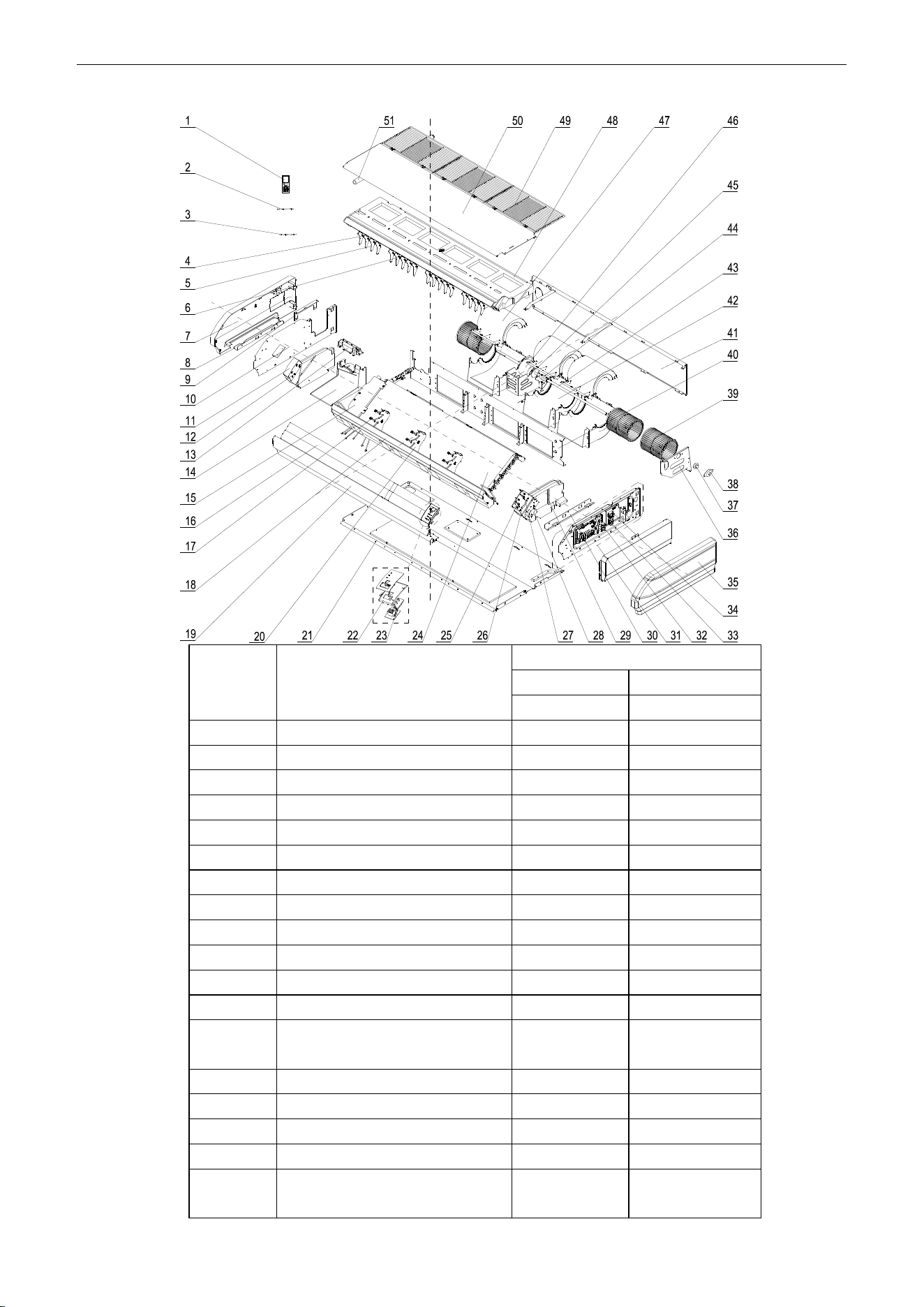
U-Match Series DC Inverter Service Manual
183
Model: UMAT36HP230V1AF exploded view and spare parts list.
NO.
Name of Part
UMAT36HP230V1AF
Product Code
ED020N1101
Part Code
Quantity
1
Remote Controller
30510516
1
2
Temperature Sensor
390001923
1
3
Room Sensor
39000191
1
4
Swing Lever
10582008
2
5
Air Louver
26909418
18
6
Swing Lever
10582009
2
7
Right Cover Plate
26909422
1
8
Installation Supporting Frame
01809402
1
9
Connection Board
02229406
1
10
Right Side Plate Sub-Assy
01319408
1
11
Right Foam Assy
12509425
1
12
Axile Bush
10542704
2
13
Plate Board of Water Releasing
Flume
26909442
1
14
Water Releasing Flume
26909441
1
15
Connected board (evaporator)
01349413
1
16
Guide Louver
26909432
2
17
Rotating Shaft
26909430
6
18
Front Connection Board Foam
Assy
12509424
1
U-Match Series DC Inverter Service Manual
184
19
Front Connection Board
01349408P
1
20
Supporter
26909409
3
21
Rear Side Plate Assy
01319400005
1
22
Fixed Mount
26909426R
1
23
Display Board
30294000009
1
24
Evaporator Assy
01029400050
1
25
Rotating Shaft
26909413
1
26
Connecting Rod
26909411
1
27
Rotating Shaft
26909412
1
28
Stepping Motor
1521240206
1
29
Left Foam Assy
12509408
1
30
Installation Supporting Frame
01809401
1
31
Electric Box Assy
01399400116
1
32
Main Board
30224000029
1
33
Terminal Board
4201025301
1
34
Terminal Board
42010178
1
35
Left Cover Plate
2690941601
1
36
Bracket 1
01809404
1
37
O-Gasket of Bearing
76512404
1
38
Support Of Motor Bearing
01792408
1
39
Centrifugal fan
1041410101
3
40
Clapboard Sub-Assy
01249400002
1
41
Rear Connection board
01349418
1
42
Front Volute Casing
26905208
3
43
Rotary Axis Sub-Assy
73018052
1
44
Joint Slack
73018731
1
45
Motor Support Sub-Assy
01809400029
1
46
Brushless DC Motor
15705200005
1
47
Rear Volute Casing
26909419
3
48
Water Tray Assy
01289405
1
49
Front Grill
26909434
1
50
Top Cover Board Sub-assy
01269405
1
51
Drainage Pipe Sub-assy
05235434
1
Above data is subject to change without notice, pls reference the SP in global service website.
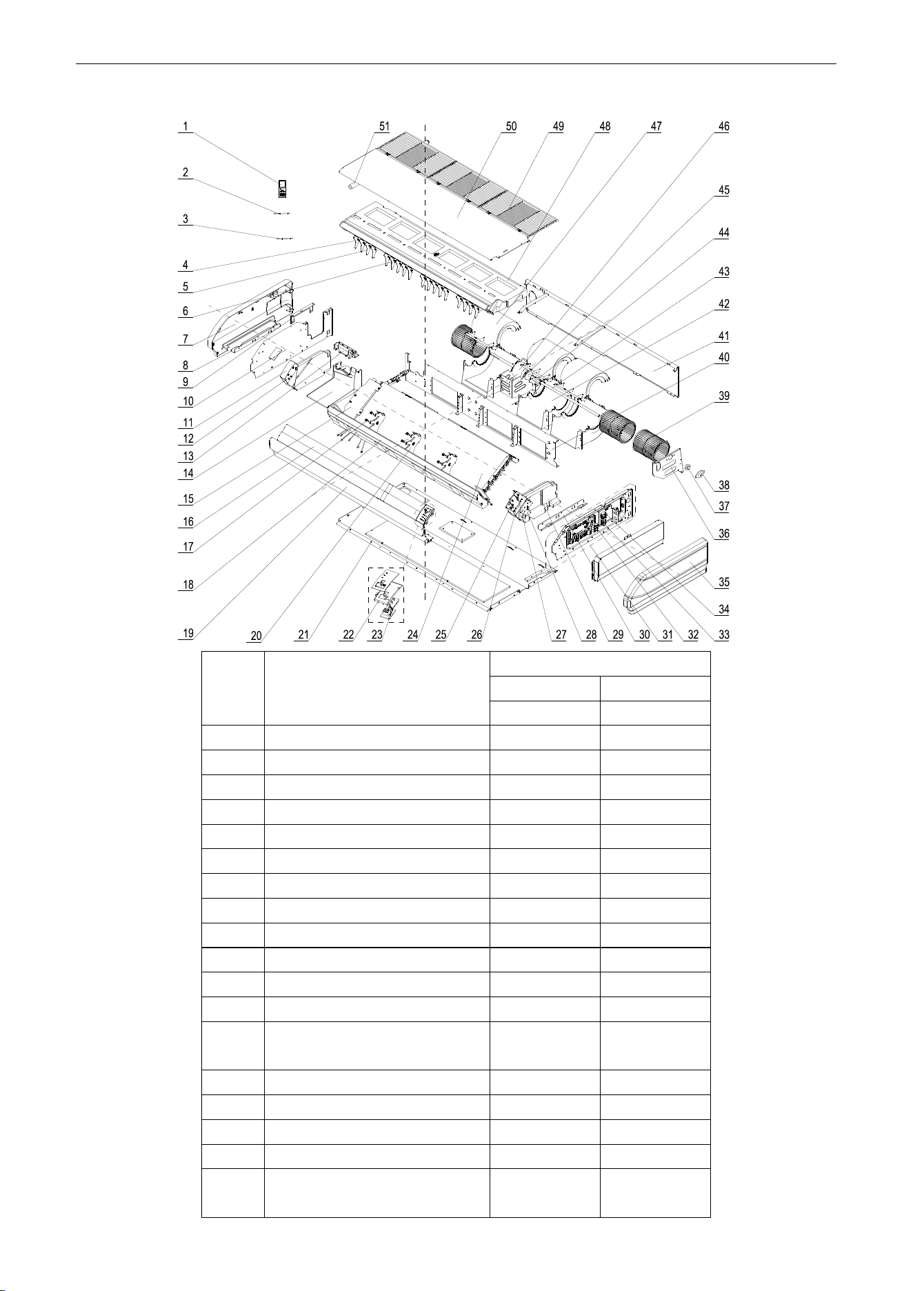
U-Match Series DC Inverter Service Manual
185
Model: UMAT42HP230V1AF exploded view and spare parts list.
NO.
Name of Part
UMAT42HP230V1AF
Product Code
ED020N1130
Part Code
Quantity
1
Remote Controller
30510516
1
2
Temperature Sensor
390001923
1
3
Room Sensor
39000191
1
4
Swing Lever
10582008
2
5
Air Louver
26909418
18
6
Swing Lever
10582009
2
7
Right Cover Plate
26909422
1
8
Installation Supporting Frame
01809402
1
9
Connection Board
02229406
1
10
Right Cover Plate
01319408
1
11
Right Foam Assy
12509425
1
12
Axile Bush
10542704
2
13
Plate Board of Water Releasing
Flume
26909442
1
14
Water Releasing Flume
26909441
1
15
Connected board (evaporator)
01349413
1
16
Guide Louver
26909432
2
17
Rotating Shaft
26909430
6
18
Front Connection Board Foam
Assy
12509424
1
U-Match Series DC Inverter Service Manual
186
19
Front Connection Board
01349408P
1
20
Supporter
26909409
3
21
Rear Side Plate Assy
01319400005
1
22
Fixed Mount
26909426R
1
23
Display Board
30294000009
1
24
Evaporator Assy
01029400049
1
25
Rotating Shaft
26909413
1
26
Connecting Rod
26909411
1
27
Rotating Shaft
26909412
1
28
Stepping Motor
1521240206
1
29
Left Foam Assy
12509408
1
30
Installation Supporting Frame
01809401
1
31
Electric Box Assy
01399400116
1
32
Main Board
30224000029
1
33
Terminal Board
4201025301
1
34
Terminal Board
42010178
1
35
Left Cover Plate
2690941601
1
36
Bracket 1
01809404
1
37
O-Gasket of Bearing
76512404
1
38
Support Of Motor Bearing
01792408
1
39
Centrifugal fan
1041410101
3
40
Clapboard Sub-Assy
01249400002
1
41
Rear Connection board
01349418
1
42
Front Volute Casing
26905208
3
43
Rotary Axis Sub-Assy
73018052
1
44
Joint Slack
73018731
1
45
Motor Support Sub-Assy
01809400029
1
46
Brushless DC Motor
15705200005
1
47
Rear Volute Casing
26909419
3
48
Water Tray Assy
01289405
1
49
Front Grill
26909434
1
50
Top Cover Board Sub-assy
01269405
1
51
Drainage Pipe Sub-assy
05235434
1
Above data is subject to change without notice, pls reference the SP in global service website.
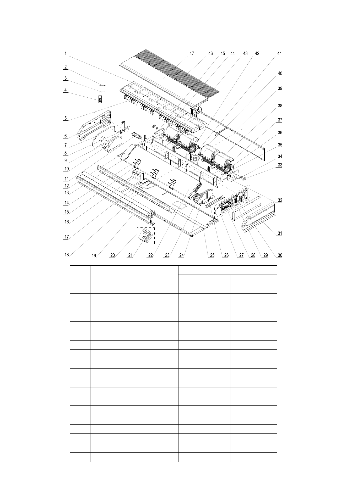
U-Match Series DC Inverter Service Manual
187
Model: UMAT48HP230V1AF exploded view and spare parts list.
NO.
Name of Part
UMAT48HP230V1AF
Product Code
ED020N1111
Part Code
Quantity
1
Water Tray Assy
01289401
1
2
Tube sensor
3900020720G
1
3
Room Sensor
39000191
1
4
Remote Controller
30510516
1
5
Air Louver
26909418
24
6
Right Cover Plate
26909422
1
7
Right Side Plate Sub-Assy
01319408
1
8
Connection Board
02229406
1
9
Right Foam Assy
12509425
1
10
Axile Bush
10542704
2
11
Plate Board of Water Releasing
Flume
26909442
1
12
Installation Supporting Frame
01809402
1
13
connected board (evaporator)
01349412
1
14
Rotating Shaft
26909430
6
15
Supporter
26909409
3
16
Water Releasing Flume
26909441
1
17
Foam Sub-assy of Front Connect
12509434
1
U-Match Series DC Inverter Service Manual
188
Board
18
Guide Louver
10619405
2
19
Front Connection Board
01349404P
1
20
Display Board
30294000009
1
21
Fixed Mount
26909426R
1
22
Evaporator Assy
0102947101
1
23
Stepping Motor
1521240206
2
24
Left Foam Assy
12509437
1
25
Rear Side Plate Sub-Assy
01319442
1
26
Installation Supporting Frame
01809421
1
27
Electric Box Assy
01399400115
1
28
Main Board
30224000029
1
29
Terminal Board
4201025301
1
30
Terminal Board
42010178
1
31
Left Cover Plate
2690941601
1
32
Bracket 1
01809404
1
33
Support Of Motor Bearing
01792408
2
34
O-Gasket of Bearing
76512404
2
35
Front volute casing
26905208
4
36
Rotary Axis Sub-Assy
73018052
2
37
Centrifugal fan
1041410101
4
38
Rear volute casing
26909419
4
39
Rear Connection board
01349419
1
40
Motor Support Sub-Assy
0180940002901
1
41
Brushless DC Motor
15709400005
1
42
Joint Slack
73018731
2
43
Clapboard Sub-Assy
01249400006
1
44
Drainage Pipe Sub-assy
05235434
1
45
Supporter
01809403
1
46
Front Grill sub-assy
01579401
4
47
Top Cover Board Sub-assy
01269400002
1
Above data is subject to change without notice, pls reference the SP in global service website.

U-Match Series DC Inverter Service Manual
189
JF00302305
GREE_U-MATCH_SERVICE_A_020620