Loading ...
Loading ...
Loading ...

110CT425A/W, 110FB425A/W 5
Installation
Before you begin
§ All dispensers must be installed level in both directions to ensure proper operation.
§ All countertop dispensers provide the option of taking utilities out the bottom or back of the dispenser.
See counter cut-out (Fig. 2) for bottom exiting utilities on units with and without drain pans. For installations
where utilities will exit through back of dispenser, refer to back view drawings.
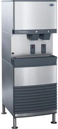
Installing freestanding dispensers
1. Position dispenser in desired location and adjust legs to level in both directions.
2. Connect water supply to 3/8" FPT tting on back of dispenser (Fig. 1).
3. Connect separate drain lines to 3/4" MPT dispenser drain tting, and 3/4" MPT ice machine drain tting
on back of dispenser.
4. Run drain lines to wall or oor drain. If ice machine drain tting is below an intended wall drain, a
condensate pump must be used.
5. If ice machine is a water-cooled unit, connect water-cooled condenser supply line to 3/8" FPT condenser
inlet tting on back of dispenser.
Note: Do not run condenser supply water through ice machine water lter system.
6. Connect condenser drain line to 3/8" FPT condenser outlet tting on back of dispenser.
Important: Do not connect condenser drain line to any other drain lines.
7. Plug dispenser into 15A rated NEMA 5-15 circuit.
8. Remove front cover of base section by removing two screws at bottom corners of cover. Allow cover to
drop approximately 3/8" (5 mm) and pull forward.
9. Turn on water supply and check for leaks.
Loading ...
Loading ...
Loading ...