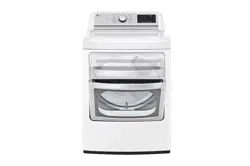

DRYER
OWNER'S MANUAL
Read this owner’s manual thoroughly before operating the appliance and keep it handy for
reference at all times.
DLEX7900*E DLGX7901*E
DLEX7800*E DLGX7801*E
DLEX7880*E DLGX7881*E
ENGLISH ESPAÑOL
MFL70442605
Rev.10_120420
www.lg.com
Copyright © 2019-2020 LG Electronics Inc. All Rights Reserved.

2
TABLE OF CONTENTS
TABLE OF CONTENTS
3
SAFETY INSTRUCTIONS
4 IMPORTANT SAFETY INSTRUCTIONS
7 GROUNDING INSTRUCTIONS
8
PRODUCT FEATURES
9
PRODUCT OVERVIEW
9 Parts
9 Accessories
9 Safety Tether Kit
9 Two-Way Reversible Door (on some models)
10
INSTALLATION
10 Installation Overview
10 Product Specifications
11 Installation Location Requirements
11 Clearances
13 Leveling the Dryer
13 Reversing the Door
21 Installing the Side Vent Kit
22 Venting the Dryer
25 Connecting Gas Dryers
27 Connecting Electric Dryers
31 Final Installation Check
32 Installation Test (Duct Check)
34
OPERATION
34 Using the Dryer
35 Check the Lint Filter Before Every Load
35 Sorting Loads
35 Loading the Dryer
36 Using the LG EasyLoad
TM
37 Control Panel
39 Cycle Guide
41 Cycle Settings and Options
43 Steam Functions (Steam Models)
44 Steam Cycle Guide
45
SMART FUNCTIONS
45 LG ThinQ Application
48 Smart Diagnosis™ Function
49
MAINTENANCE
49 Regular Cleaning
50
TROUBLESHOOTING
50 FAQs: Frequently Asked Questions
50 User Support Videos
51 Before Calling for Service
59
WARRANTY (USA)
3
SAFETY INSTRUCTIONS
IMPORTANT SAFETY INSTRUCTIONS
READ ALL INSTRUCTIONS BEFORE USE
Safety for a Dryer
WARNING
WARNING:
Fire Hazard
Failure to follow safety warnings exactly could result in serious injury,
death or property damage.
Do not install a booster fan in the exhaust duct.
Install all clothes dryer in accordance with the installation instructions of
the manufacturer of dryer.
FIRE OR EXPLOSION HAZARD
Failure to follow safety warnings exactly could result in serious injury,
death or property damage.
• Donotstoreorusegasolineorotherflammablevaporsandliquidsinthe
vicinityofthisoranyotherappliance.
• WHATTODOIFYOUSMELLGAS
- Do not try to light any appliance.
- Do not touch any electrical switch; do not use any phone in your
building.
- Clear the room, building or area of all occupants.
- Immediately call your gas supplier from a neighbor’s phone. Follow the
gas supplier’s instructions.
- If you cannot reach your gas supplier, call the fire department.
• Installationandservicemustbeperformedbyaqualifiedinstaller,service
agency or your gas supplier.
4
SAFETY INSTRUCTIONS
WARNING - RISK OF FIRE
Install the clothes dryer according to the manufacturer’s instructions and
local codes.
•Clothesdryerinstallationmustbeperformedbyaqualifiedinstaller.
• Donotinstallaclothesdryerwithflexibleplasticventingmaterials.If
flexible metal (foil type) duct is installed, it must be of a specific type
identified by the appliance manufacturer as suitable for use with clothes
dryers.Flexibleventingmaterialsareknowntocollapse,beeasily
crushed, and trap lint. These conditions will obstruct clothes dryer airflow
and increase the risk of fire.
•Toreducetheriskofsevereinjuryordeath,followallinstallation
instructions.
Yoursafetyandthesafetyofothersisveryimportant.
We have provided many important safety messages in this manual and on your appliance. Always read and
obey all safety messages.
This is the safety alert symbol.
This symbol alerts you to potential hazards that can kill or hurt you and others.
All safety messages will follow the safety alert symbol and either the word DANGER, WARNING, or
CAUTION.
These words mean:
DANGER
-
You will be killed or seriously injured if you
do not
immediately follow instructions.
WARNING
- You may be killed or seriously injured if you do not follow instructions.
CAUTION
- You may be slightly injured or cause damage to the product if you do not follow
instructions.
All safety messages will tell you what the potential hazard is, tell you how to reduce the chance of injury,
and tell you what may happen if the instructions are not followed.

5
SAFETY INSTRUCTIONS
IMPORTANT SAFETY INSTRUCTIONS
WARNING
To reduce the risk of fire, electric shock, or injury to persons when using your appliance, follow basic
precautions, including the following:
Installation
•
Keep area around the exhaust opening and adjacent
surrounding areas free from the accumulation of lint,
dust, and dirt.
•
Do not install or store this appliance where it will be
exposed to the weather.
•
Do not place items exposed to cooking oils in
your dryer.
Items contaminated with cooking oils may
contribute to a chemical reaction that could cause a
load to catch fire.
•
Properly ground the dryer to conform with all
governingcodesandordinances.
Follow the details
in the installation instructions. Electric shock may result
if the dryer is not properly grounded.
•
Before use, the dryer must be properly installed as
described in this manual.
Electric shock may result if
the dryer is not properly grounded.
•
Install and store the dryer where it will not be exposed to
temperatures below freezing or exposed to the weather.
•
Allrepairsandservicingmustbeperformedby
authorizedservicepersonnelunlessspecifically
recommended in this Owner’s Manual. Use only
authorized factory parts.
Failure to follow this warning
may result in serious injury, fire, electric shock, or death.
•
To reduce the risk of electric shock, do not install
the dryer in humid spaces.
Failure to follow this
warning may result in serious injury, fire, electric shock,
or death.
•
Connect to a properly rated, protected, and sized
powercircuittoavoidelectricaloverload.
Improper
power circuits may melt, creating electric shock and/or
fire hazard.
•
Removeallpackingitemsanddisposeofall
shipping materials properly.
Failure to do so may
result in burns, fire, explosion, or death.
•
Placethedryeratleast18-inch(45.7cm)abovethe
floor for a garage installation.
Failure to do so may
result in burns, fire, explosion, or death.
•
Keep all packaging from children.
Packaging material
can be dangerous for children. There is a risk of
suffocation.
•
Do not install near another heat source such as a
stove,ovenorheater.
Failure to follow this warning
may result in product deformation, smoke, or fire.
•
Do not place candles, smoking materials, or other
flammables on top of the product. Dripping wax, smoke,
or fire may result.
•
Removeallprotectivevinylfilmfromtheproduct.
Failure to do so may result in product damage, smoke,
or fire.
•
Gas dryers MUST be exhausted to the outside.
Failure to follow these instructions may result in fire or
death.
•
The dryer exhaust system must be exhausted to the
outside of the dwelling. If the dryer is not exhausted
outdoors, some fine lint and large amounts of moisture
will be expelled into the laundry area. An accumulation
of lint in any area of the home may create a health and
fire hazard.
•
Use only rigid, semi-rigid or flexible metal 4-inch
(10.2 cm) diameter duct inside the dryer cabinet or
for exhausting to the outside. Use of plastic or other
combustible ductwork may cause fire. Punctured
ductwork may cause fire if it collapses or becomes
otherwise restricted in use or during installation.
•
Ductworkisnotprovidedwiththedryer,andyou
should obtain the necessary ductwork locally. The
endcapshouldhavehingeddamperstoprevent
backdraft when the dryer is not in use.
Failure to
follow these instructions may result in fire or death.
•
The exhaust duct must be 4-inch (10.2 cm) in
diameter with no obstructions. The exhaust duct
should be kept as short as possible. Make sure
to clean any old ducts before installing your new
dryer.
Failure to follow these instructions may result in
fire or death.
•
Rigid, semi-rigid or flexible metal ducting is
recommended for use between the dryer and the
wall. All non-rigid metal transition duct must be
UL-listed. Use of other materials for transition
duct could affect drying time.
Failure to follow these
instructions may result in fire or death.
•
Do not use sheet metal screws or other fasteners
which extend into the duct that could catch lint and
reduce the efficiency of the exhaust system. Secure
all joints with duct tape. For complete details, follow
the Installation Instructions.
Failure to follow these
instructions may result in fire or death.
•
Certain internal parts are intentionally not
gronunded and may present a risk of electronic
shock only during serving.
Service personnel - do not contact the following
parts while the appliance is energized: CONTROL
BOARD

6
SAFETY INSTRUCTIONS
Operation
•
Read all instructions before using the appliance.
•
Do not dry articles that have been previously
cleaned in, washed in, soaked in, or spotted with
gasoline, dry-cleaning solvents, or other flammable
or explosive substances, as they give off vapors
that could ignite or explode.
•
Do not reach into the appliance if the drum is
moving.
•
Do not allow children to play on or in the appliance.
Close supervision of children is necessary when
the appliance is used near children.
•
Do not use fabric softeners or products to eliminate
static unless recommended by the manufacturer of
the fabric softener or product.
•
Do not use heat to dry articles containing foam
rubber or similarly textured rubber-like materials.
•
Do not tamper with controls.
•
Always check the inside of the dryer for foreign
objects. Failure to follow these instructions may
result in fire or death.
•
Do not store plastic, paper, or clothing that may
burn or melt on top of the dryer during operation.
Failure to follow these instructions may result in fire
or death.
•
Be careful when opening and closing the door.
Fingers and hands can get caught in the door and
cause injury if the door drops forward unexpectedly.
•
Donotplaceheavyitemsonorleanagainstthe
top of the door when it is open.
•
Do not attempt to pull the hamper door open
more than 40 degrees.
•
The dryer could tip forward, causing injury or
damage.
•
Do not place items on the top of the dryer.
•
Gas appliances can cause minor exposure to four
potentially hazardous substances, namely benzene,
carbon monoxide, formaldehyde, and soot, caused
primarily by the incomplete combustion of natural
gas or LP fuels.
•
Properly adjusted dryers will minimize incomplete
combustion. Exposure to these substances can be
minimized further by properly venting the dryer to
the outdoors.
•
Do not place items exposed to cooking oils in your
dryer. Items contaminated with cooking oils may
contribute to a chemical reaction that could cause
a load to catch fire. To reduce the risk of fire due
to contaminated loads, the final part of a tumble
dryer cycle occurs without heat (cool down period).
Avoid stopping a tumble dryer before the end of the
drying cycle unless all items are quickly removed
and spread out so that the heat is dissipated.
•
Do not let children or pets climb inside the dryer
drum.
•
Do not put living animals such as pets inside the
product.
SAVE THESE INSTRUCTIONS
•
Do not put any part of your body, such as your
hands or feet, or metal objects under the product.
•
Do not let your hand get pinched when opening or
closing the dryer door.
Steam (steam model):
•
Do not open the dryer door during steam
cycles.
Failure to follow these instructions may
result in a burn hazard.
•
Donotdryarticlesthathavebeenpreviously
cleaned in, washed in, soaked in, or spotted
withgasoline,dry-cleaningsolvents,orother
flammableorexplosivesubstancesastheygive
offvaporsthatcouldigniteorexplode.
Failure to
follow these instructions may result in fire or death.
•
Do not fill the steam feeder with gasoline,
drycleaningsolvents,orotherflammableor
explosivesubstances.
Failure to follow these
instructions may result in fire or death.
•
Do not touch the steam nozzle in the drum
during or after the steam cycles.
Failure to follow
these instructions may result in a burn hazard.
•
Donotfillthesteamfeederwithhotwater(over
86 °F/30 °C).
Failure to follow these instructions
may result in a burn hazard.
Maintenance
•
Do not repair or replace any part of the appliance
or attempt any servicing unless specifically
recommended in the user maintenance instructions
or in published user-repair instructions that you
understand and have the skills to carry out.
•
Clean the lint filter before or after each load.
•
The interior of the appliance and exhaust duct
should be cleaned periodically by qualified service
personnel.
•
Before the appliance is removed from service
or discarded, remove the door to the drying
compartment.
•
Certain internal parts are intentionally not
gronunded and may present a risk of electronic
shock only during serving.
Service personnel - do not contact the following
parts while the appliance is energized: CONTROL
BOARD

7
SAFETY INSTRUCTIONS
GROUNDING INSTRUCTIONS
WARNING
Improperconnectionoftheequipment-groundingconductormayresultinariskofelectricshock.
Checkwithaqualifiedelectricianorservicepersonifyouareindoubtthattheapplianceisproperly
grounded.
•
This appliance must be grounded.
In the event
of malfunction or breakdown, grounding will reduce
the risk of electric shock by providing a path of least
resistance for electric current.
•
Thisappliancemustbeequippedwithacord
havinganequipment-groundingconductorand
a grounding plug.
The plug must be plugged into
an appropriate outlet that is properly installed and
grounded in accordance with all local codes and
ordinances.
•
Do not modify the plug.
If it will not fit the outlet,
have a proper outlet installed by a qualified
electrician.
•
This appliance must be connected to a
grounded metal, permanent wiring system or
anequipment-groundingconductormustbe
run with the circuit conductors and connected
totheequipment-groundingterminalorlead
on the appliance.
Electric shock may result if the
dryer is not properly grounded.
•
The dryer should always be plugged into its
ownindividualelectricaloutletwhichhasa
voltageratingthatmatchestheratingplate.
This
provides the best performance and also prevents
overloading house wiring circuits which can cause
a fire hazard from overheated wires.
•
Neverunplugyourdryerbypullingonthe
power cord. Always grip the plug firmly and pull
straight out from the outlet.
The power cord may
be damaged, resulting in a risk of fire and electric
shock.
•
Repair or replace immediately all power
cordsthathavebecomefrayedorotherwise
damaged. Do not use a cord that shows cracks
or abrasion damage along its length or at either
end.
The power cord may melt, creating electric
shock and/or fire hazard.
•
Wheninstallingormovingthedryer,becareful
not to pinch, crush, or damage the power cord.
This will prevent injury and damage to the dryer
from fire and electric shock.
•
Do not, under any circumstances, cut or
removethegroundprongfromthepowercord.
To prevent personal injury or damage to the dryer,
the electrical power cord must be plugged into a
properly grounded outlet.
•
For personal safety, this dryer must be properly
grounded.
Failure to do so may result in electric
shock or injury.
•
Refer to the installation instructions in this
manualforspecificelectricalrequirementsfor
your model.
Failure to follow these instructions
may create an electric shock hazard and/or a fire
hazard.
•
This dryer must be plugged into a properly
grounded outlet. Electrical shock may result if
thedryerisnotproperlygrounded.Havethe
walloutletandcircuitcheckedbyaqualified
electrician to make sure the outlet is properly
grounded.
Failure to follow these instructions
may create an electric shock hazard and/or a fire
hazard.
8
PRODUCT FEATURES
PRODUCT FEATURES
Easy-to-Use Control Panel
An entire selection of user-friendly functions make operating the dryer easy.
Two-WayEasy-AccessReversingDoor
The LG EasyLoad™ can be tilted open from the top, hamper-style, allowing you to easily load the dryer without items falling
on the floor. The door still swings open to provide easy access for unloading or loading of bulkier items. The door hinge can
be reversed to adjust to the installation location.
Steam Functions (Steam Models)
LG's steam technology allows you to inject fabrics with a swirling jet of steam to refresh clothes, reduce static, and make
ironing easier. Simply select the Steam Fresh™ cycle or Wrinkle Care cycle.
Flow Sense™ Duct Blockage Sensing System Indicator
The Flow Sense™ duct blockage sensing system detects and alerts you to restrictions in the installed household ductwork
that reduce exhaust airflow through the dryer. If you see the alert: Clean or repair the ducts to remove the restrictions. Keep
your ducts free of blockage to help increase efficiency and reduce long drying times caused by blocked ducts.
Smart Diagnosis™
Should you experience any technical difficulty with your dryer, it has the capability of transmitting data via your telephone
to the Customer Information Center. The call center agent records the data transmitted from your machine and uses it to
analyze the issue, providing a fast and effective diagnosis.
LG ThinQ™
Download the new LG smart phone app to set options, self-diagnose and troubleshoot problems with the appliance, and
other useful features. This function uses Wi-Fi.
Protocol P154
Sanitization Performance of
Residential Clothes dryer
C
E
R
T
I
F
I
E
D
D
E
S
I
G
N
Protocol P154
Sanitization Performance of
Residential Clothes dryer
C
E
R
T
I
F
I
E
D
D
E
S
I
G
N
9
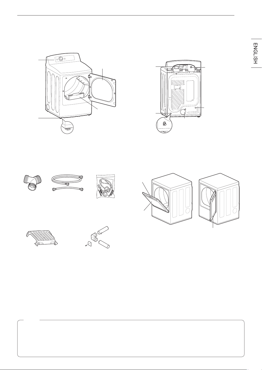
PRODUCT OVERVIEW
PRODUCT OVERVIEW
Parts
Control
panel
Leveling
feet
Reversible
door
Power cord
location
(gas models)
Water inlet valve
(on some models)
Exhaust duct
outlet
Terminal block
access panel
(electric models)
Gas connection
location
(gas models)
Lint lter
Accessories
Included Accessories
Optional accessories
Y connector
(steam models)
Hoses
(steam models)
Side vent kit
(sold separately)
Kit No. 383EEL9001B
Safety Tether Kit
(on some models)
Drying rack
(sold separately)
No. 3750EL0001C
Release
Hamper
door
Swing door
The LG EasyLoad™ feature allows you to open the
dryer door from the top, hamper-style, when loading the
dryer to help guide clothes into the drum and prevent
them from falling onto the floor. When unloading the
dryer or loading bulkier items, use the swing door for
easy access to the drum.
Safety Tether Kit
This optional kit helps prevent the dryer tipping if children climb on the door or if someone should fall onto the
door. It is recommended that you install this kit, depending on your situation, but it is not required. Follow the
customer installation instructions included with the kit to properly install the kit. If you do not install the kit, store it
out of reach of children.
NOTE
•
For your safety and for extended product life, use only authorized components. The manufacturer is not
responsible for product malfunction or accidents caused by the use of separately purchased unauthorized
components or parts.
•
The images in this guide may be different from the actual components and accessories, which are subject
to change by the manufacturer without prior notice for product improvement purposes.
Two-WayReversibleDoor
(on some models)
10
INSTALLATION
INSTALLATION
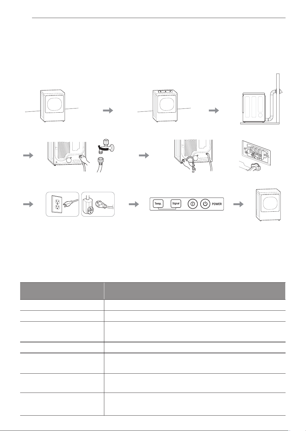
InstallationOverview
Please read the following installation instructions first after purchasing this product or transporting it to another
location.
Check and choose
the proper location
Connect the inlet hose
(steam models)
Connect gas dryers
Connect electric dryers
Plug in the power cord Installation test Test run
Gas dryer Electric dryer
Level the dryer
Vent the dryer
Product Specifications
The appearance and specifications listed in this manual may vary due to constant product improvements.
Dryer Models
DLEX7900*E, DLEX7800*E, DLEX7880*E
DLGX7901*E, DLGX7801*E, DLGX7881*E
Description
Steam Dryer
Electricalrequirements
Please refer to the rating label regarding detailed information.
Gasrequirements
NG: 4–10.5-inch WC
LP: 8–13-inch WC
Max. water pressure
20–120 psi (138–827 kPa)
Dimensions
27” (W) X 29 1/2” (D) X 44 1/4” (H), 50 1/4” (D with door open)
68.6 cm (W) X 75.0 cm (D) X 112.3 cm (H), 127.5 cm (D with door open)
Net weight
Gas dryer : 129.8 lb (58.9 kg)
Electric dryer : 124.8 lb (56.6 kg)
Drying capacity
- Normal cycle
- Steam cycle
IEC 7.3 cu.ft. (22.5 lb/10.2 kg)
IEC 7.3 cu.ft.(8 lb/3.6 kg)

11
INSTALLATION
InstallationLocationRequirements
WARNING
Read all installation instructions completely before installing and operating your dryer! It is important that you
review this entire manual before installing and using your dryer. Detailed instructions concerning electrical
connections, gas connections, and exhaust requirements are provided on the following pages.
The installation requires:
•
A location that allows for proper exhaust installation. A gas dryer must be exhausted to the outdoors. See
Venting the Dryer.
•
A grounded electrical outlet located within 2 ft. (61 cm) of either side of the dryer. See Connecting Electric
Dryers .
•
A sturdy floor to support the total dryer weight of 200 lb (90.7 kg). The combined weight of a companion
appliance should also be considered.
•
No other fuel-burning appliance can be installed in the same closet as a dryer.
Do not operate your dryer at temperatures below 45 °F (7 °C). At lower temperatures, the dryer might not shut off
at the end of an automatic cycle. This can result in longer drying times. The dryer must not be installed or stored
in an area where it will be exposed to water and/or weather. Check code requirements. Some codes limit, or do
not permit, installation of the dryer in garages, mobile homes or sleeping quarters. Contact your local building
inspector.
NOTE
•
The floor must be level, with a maximum slope of 1 inch (2.5 cm) under the entire dryer.
Clothes may not tumble properly, and automatic sensor cycles may not operate correctly if dryer is not
level.
•
For a garage installation, you will need to place the dryer at least 18-inch (46 cm) above the floor. The
standard pedestal is 15-inch (38.1 cm). You will need 18-inch (46 cm) from the garage floor to the bottom
of the dryer.
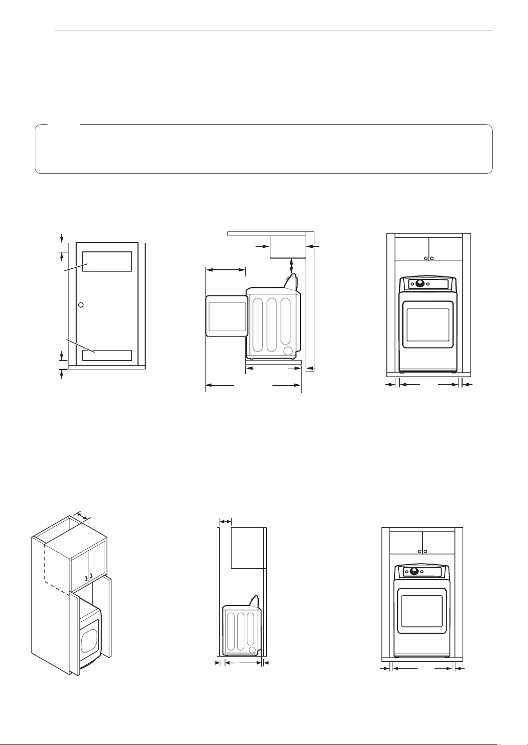
Clearances
Installation Spacing for Recessed Area or Closet Installation
The following spacing dimensions are recommended for this dryer. This dryer has been tested for clearances of
1 inch (2.5 cm) on the sides and rear. Recommended clearances should be considered for the following reasons:
•
Additional clearances should be considered for ease of installation and servicing.
•
Additional clearances might be required for wall, door and floor moldings.
•
Additional clearances should be considered on all sides of the dryer to reduce noise transfer.
For closet installation, with a door, minimum ventilation openings in the top and bottom of the door are
required. Louvered doors with equivalent ventilation openings are acceptable.
•
Companion appliance spacing should also be considered.
12
INSTALLATION
ClosetVentilationRequirements
Closets with doors must have both an upper and lower vent to prevent heat and moisture buildup in the closet.
One upper vent opening with a minimum opening of 48 sq. in. (310 cm
2
) must be installed no lower than 6 feet
above the floor. One lower vent opening with a minimum opening of 24 sq. in. (155 cm
2
) must be installed no
more than one foot above the floor. Install vent grills in the door or cut down the door at the top and bottom to
form openings. Louvered doors with equivalent ventilation openings are also acceptable.
NOTE
There should be at least a little space around the dryer (or any other appliance) to eliminate the transfer of
vibration from one appliance to another. If there is enough vibration, it could cause appliances to make noise
or come into contact, causing paint damage and further increasing noise.
Installation Spacing for Recessed Area or Closet
Closet Door Vent
Requirements
3"
(7.6 cm)
14" max.*
(35.6 cm)
1"
(2.5 cm)
1"
(2.5 cm)
27"
(68.6 cm)
3"
(7.6 cm)
50
1
/
4
"
(127.5 cm)
29
1
/
2
"
(75.0 cm)
18" min.
(45.7 cm)
21
1
/
4
"
(54 cm)
48 in.
2
(310 cm
2
)
24 in.
2
(155 cm
2
)
* Required spacing
** For side or bottom venting, 2-inch (5.1 cm) of spacing is allowed
Installation Spacing for Cabinet
For cabinet installation with a door, minimum ventilation openings in the top of the cabinet are required.
* Required spacing
7"
*
(17.8 cm)
7"
*
(17.8 cm)
5"
*
(12.7 cm)
1"
(2.5 cm)
1"
*
(2.5 cm)
1"
(2.5 cm)
29
1
/
2
"
(75.0 cm)
27"
(68.6 cm)
13
INSTALLATION
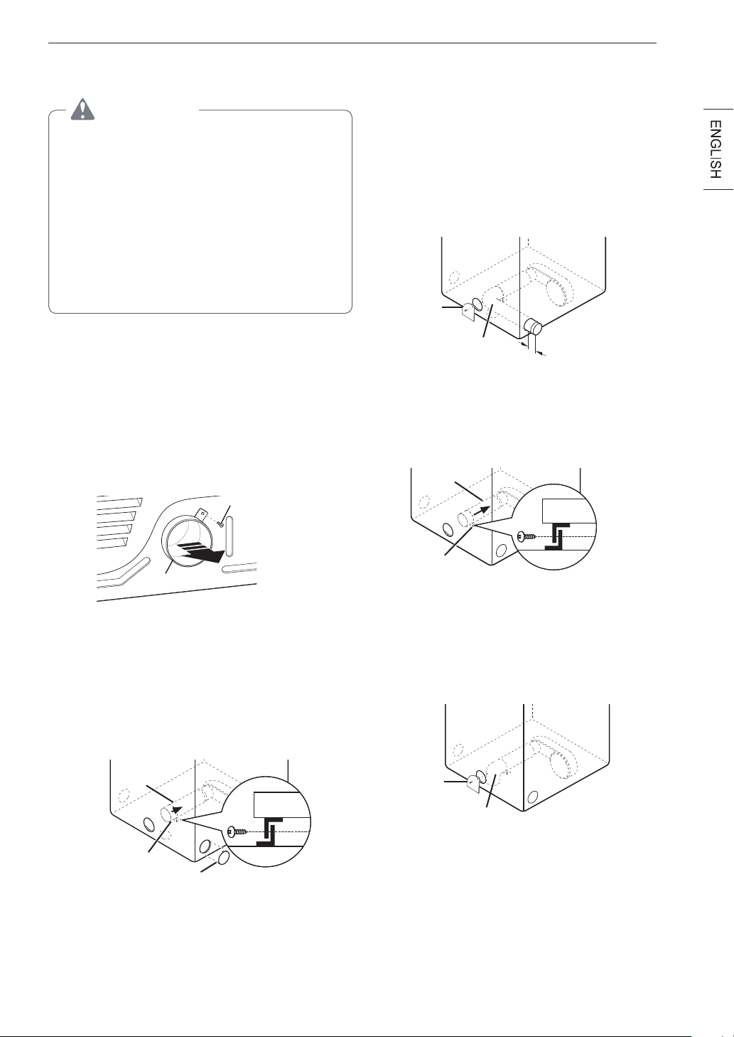
LevelingtheDryer
WARNING
To reduce the risk of injury to persons, adhere
to all industry recommended safety procedures
including the use of long-sleeved gloves and
safety glasses. Failure to follow this warning may
result in serious injury or death.
•
The appliance is heavy. Two or more people
are required when installing the dryer. Failure to
follow this warning may result in serious injury
or death.
•
To ensure that the dryer provides optimal drying
performance, it must be level. To minimize
vibration, noise, and unwanted movement, the
floor must be a perfectly level, solid surface.
NOTE
Adjust the leveling feet only as far as necessary
to level the dryer. Extending the leveling feet more
than necessary may cause the dryer to vibrate.
1
Position the dryer in the final location. Check
levelness of dryer from side to side. Repeat from
front to back
Place level here
Place level here
Not Level Not LevelLevel
2
Use an adjustable wrench to turn the leveling
feet. Unscrew the legs to raise the dryer or
screw in the legs to lower it. Raise or lower with
the leveling feet until the dryer is level from side
to side and front to back. Make sure that all four
leveling feet are in firm contact with the floor.
If you are installing the dryer on the optional pedestal,
you must use the leveling feet on the pedestal to level the
dryer. The dryer leveling feet should be fully retracted.
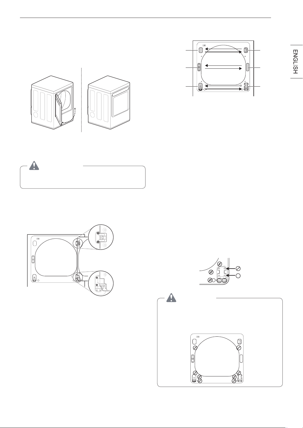
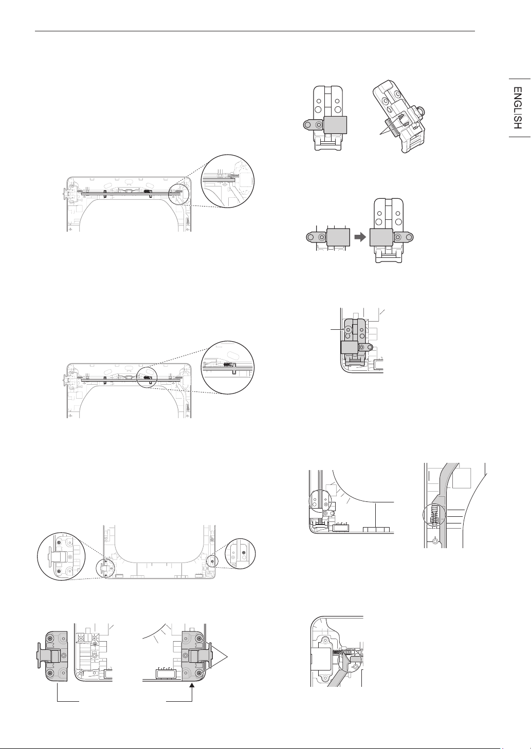
ReversingtheDoor
Before you Begin
NOTE
Servicecallstoreversethedoorarenotcovered
under the product warranty.
•
The door reversal process for the two-way door
is more complex than for a conventional dryer
door. Read through these instructions in their
entirety before beginning the process, in order to
gauge whether to have the procedure done by a
professional installer or service person.
•
A support video is also provided at http://www.
lg.com/us/support/videos/video-tutorials-view,
How to Reverse the Door – LG EasyLoad™ Dryer.
ToolsRequired
•
Phillipsscrewdriver
•
Largeflatbladescrewdriver
(recommended
for hinge screws if they are tight or your Phillips
screwdriver is worn)
•
Smallflatbladescrewdriver
(for lifting out parts)
WARNING
THE DRYER DOOR IS VERY LARGE AND
HEAVY. Failure to follow the instructions below
may result in damage to the dryer, property
damage or personal injury.
•
To avoid damage to the dryer or the door,
support the door with a stool or box that fits
under the door, or have an assistant support
the weight of the door.
•
Avoid dropping the door to avoid damage to the
door or the floor.
•
Unplug the dryer or turn off power at the main
circuit breaker before beginning door reversal.

14
INSTALLATION
c. Remove the hinge cover by gently prying it up
with a flat blade screwdriver, being careful not
to scratch the paint. Rotate the hinge cover
180 degrees and install it on the opposite side,
where the hinge was attached.
4
With the door on a protected surface, remove all
screws on each side of the door and lift off the
inner door frame using a flat blade screwdriver.
Remove the latch hook and blank and install
them on the opposite side.
Latch hook
Blank
Inner door
frame
5
Remove the 4 screws securing the hinges to
the door frame. Remove the two plastic cover
caps. Reinstall the hinges and cover caps on the
opposite sides from which they were removed.
Cover cap
Hinge
assembly
6
With the hinges and cover caps in the new
locations, remount the inner door frame onto the
outer door frame with the screws removed in
step 4 above.
WARNING
Be sure to support the weight of the door before
installing the hinge screws.
DoorReversalInstructions
NOTE
The instructions here are for changing the door
swing from a right to a left side hinge. If the
door has been reversed, and it is necessary to
change it back, use care when following these
instructions. Some of the illustrations and the left/
right references will be reversed, and you will
need to read the instructions carefully.
WARNING
Be sure to support the weight of the door before
removing the hinge screws.
Swing door
1
Open the door from the side so that the hinge
screws are accessible.
2
Removethefourhingescrews.
While supporting the door, remove the four hinge
screws, two from each hinge. Set the door aside
face down on a protected surface to prevent
damage to the door or the work surface.
3
Reversethecomponentsonthecabinet.
hinge
hinge
cover
hinge
cover
latch
mechanism
latch
hole
cover
hinge
a. Use a Phillips screwdriver to remove the two
screws and the latch mechanism on the front
panel of the cabinet.
b. Remove the latch hole cover by gently prying it
up with a flat blade screwdriver, being careful
not to scratch the paint. Install the latch hole
cover on the opposite side, where the latch
mechanism was removed. Install the latch
mechanism in the position from which you
removed the latch hole cover, using the two
screws removed in step a.
15
INSTALLATION
7
Reinstall the door.
While supporting the door, install the four hinge
screws removed in step 2. Test the swing of
the door to make sure the hinges and latch are
properly aligned and that the door opens, closes
and latches properly in both directions.
Swing
Door
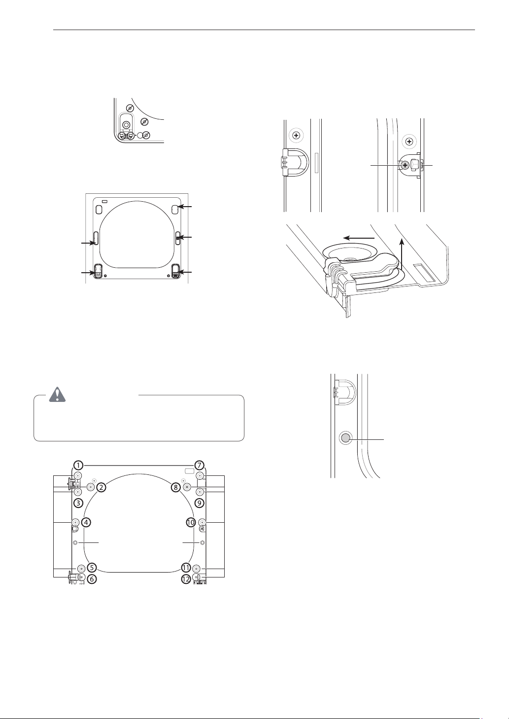
Easy load door (on some models)
WARNING
Be sure to support the weight of the door before
installing the hinge screws.
ON THE CABINET :
1
Open the door from the side so that the hinge
screws are accessible.
Two large
screws
Two small
screws
2
Removethefourhingescrews
While supporting the door, remove the four hinge
screws, two from each hinge. Set the door aside
face down on a protected surface to prevent
damage to the door or the work surface.
3
Reversethecomponentsonthecabinet.
Upper
hinge
Hinge
cover
Hinge
latch
mechanism
Latch
hole
cover
Hinge
bracket
a. Use a Phillips screwdriver to remove the two
screws and the latch mechanism on the front
panel of the cabinet.
b. Remove the latch hole cover by gently prying it
up with a flat blade screwdriver, being careful
not to scratch the paint. Install the latch hole
cover on the opposite side, where the latch
mechanism was removed. Install the latch
mechanism in the position from which you
removed the latch hole cover, using the two
screws removed in step a.
c. Remove the hinge cover by gently prying it up
with a flat blade screwdriver, being careful not
to scratch the paint. Rotate the hinge cover
180 degrees and install it on the opposite side,
where the upper hinge was attached.
d. Reverse the hinge and the hinge bracket at
the bottom of the cabinet. Remove the two
screws from the hinge bracket at the bottom
right and remove the hinge bracket. Remove
the lower of the two screws behind the hinge
bracket. Do NOT remove the upper screw
behind the hinge bracket. Set the parts aside.
CAUTION
Do NOT remove any of the eight screws on the
face of the cabinet (marked below). Doing so
could result in damage to the dryer and the need
for a service call to repair the dryer.
16
INSTALLATION
e. Remove the three screws on the hinge at the
bottom left. Remove the hinge and reinstall it
on the right side. The top screw will occupy
the hole where you removed the screw behind
the hinge bracket in step d.
f. Install the hinge bracket removed in step d on
the bottom left side, first installing one screw
behind the hinge bracket.
hinge
cover
hinge
bracket
latch hole
cover
latch
mechanism
hinge
Cabinet Reversal complete
ON THE DOOR:
4
Liftoffthedoorcover.
With the door laid inside facing up on a protected
surface, remove the twelve screws on the inside
of the door. Carefully lift off the door cover with
the help of a small flat blade screwdriver inserted
in the upper corner (circled below).
WARNING
The edges of the door cover may be sharp. Take
care when handling, or wear gloves to avoid
injury.
Hole
plug
Twelve screws
Side
Interlock
button
5
Switchthedoorstrikeandtheblankcover.
Remove the two screws on the door cover that
secure the door strike.
Switch the door strike and the blank cover,
installing them on the opposite sides from which
they were removed.
Long
screw
Short
screws
Blank cover Door strike
Pull
Raise
Remove blank cover
Gently pry out the hole plug on the side of
the door cover and install it in the hole on the
opposite side.
Hole
plug
Set the door cover aside.
17
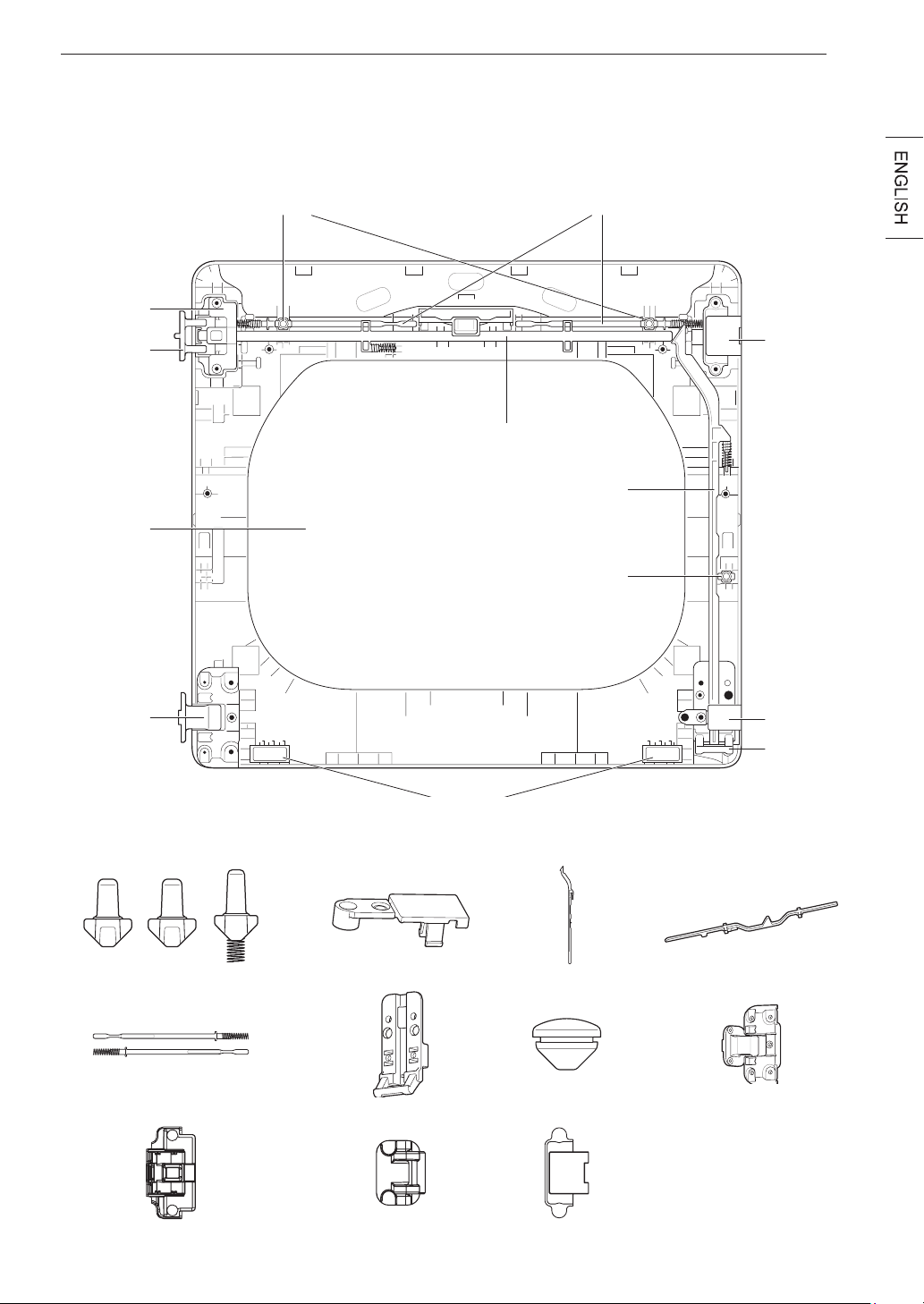
INSTALLATION
6
Reversethecomponentsinsidethedoor.
You will now be removing and reversing various components inside the door. See below for a detailed
diagram and identification of the inner structure and parts of the door. (The diagram shows the “before view”
of the door, with the default set-up for a right side hinge swing. After following these instructions, your door
should be a mirror image of the illustration.)
Upper
hinge lter
Side lock rod
Side Interlock button
Lower
hinge ller
Lower
hinge
bracket
Bumpers
Inner lock rodsTop interlock buttons
Top lock rod
Upper
hinge
assembly
Upper
hinge
pivot
Glass
Lower
hinge
assembly
Interlock buttons
Upper hinge assembly Upper hinge pivot Upper hinge ller
Inner lock rods
Low hinge ller
Lower hinge bracket
Top lock rod
Lower hinge assembly
Side lock rod
Hole plug
18
INSTALLATION
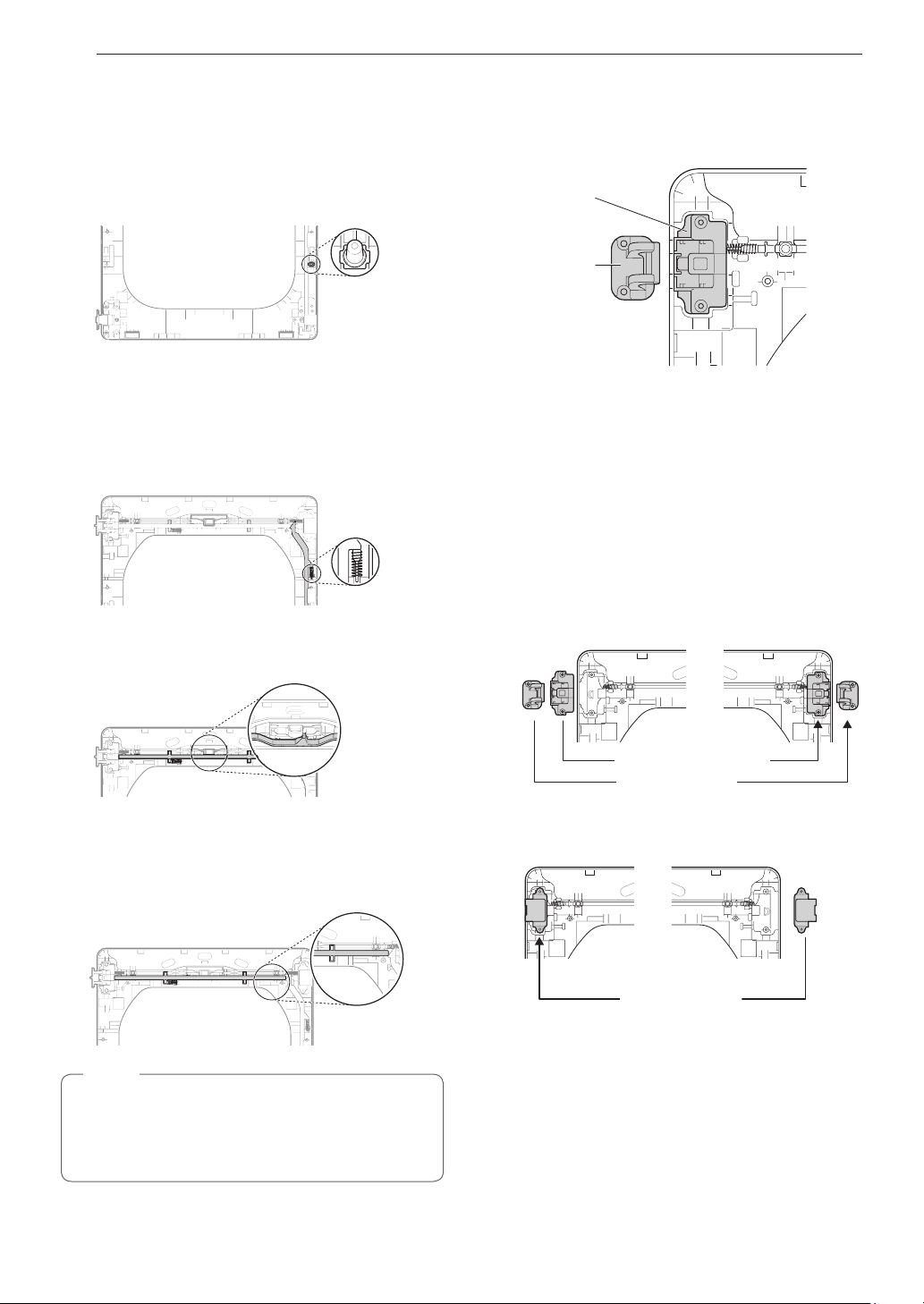
7
Lift out the gray interlock button in the side
of the door.
Make sure to remove the spring with the
interlock button and to keep the two together.
Set the interlock button aside. Do not confuse
these with the interlock buttons from the top of
the outer door.
8
Removethesidelockrod.
Remove the side lock rod from the lower hinge
bracket by lifting the top end of the rod and
sliding it toward the top of the door. The spring
should remain attached to the lock rod. Set the
lock rod aside.
Spring
9
Removethetoplockrod.
a. Slide the lock rod to the right to remove it from
the hinge assembly on the left side.
b. While sliding the lock rod right, lift the right end
up and out of the guides.
Do not remove the two inner lock rods and
two interlock buttons (see page 17) located
underneath the top lock rod. They do NOT need
to be reversed.
NOTE
10
Removetheupperhingepivot.
Once the top lock rod has been removed, the
hinge pivot can easily be removed from the
hinge assembly on the upper left and set aside.
Upper hinge
assembly
Upper
hinge
pivot
11
Reversetheupperhingeassemblyand
hinge filler.
Lift out the upper hinge filler (on the right) and
set it aside.
Carefully lift the upper hinge assembly (on the
left) out of the outer door frame, using a small
flat blade screwdriver if necessary. Rotate
the hinge assembly 180 degrees and install it
on the upper right side of the outer door. You
will need to press firmly to install the hinge
assembly.
The hinge pivot removed in step 11 will be
installed later.
Upper hinge assembly
Upper hinge pivot
Now rotate the hinge filler 180 degrees and
install it on the upper left side of the door.
Upper hinge ller
19
INSTALLATION
12
Reinstall the top lock rod.
Rotate the top lock rod (removed in step 10)
180 degrees end for end from its original
position and reinstall it. The spring should now
be to the right of center, with the spring on the
side of the rod facing the top of the door.
a. Insert the right end of the lock rod into the
right hinge assembly. Make sure the rod is
aligned with the guides in the door panel.
b. Lower the rod into position, sliding it to
bypass the center handle, making sure to
align the lock rod with the guides all the
way across the door panel. When released,
the lock rod should slide completely into
the hinge assembly on the right. Slide the
lock rod back and forth to make sure it is
correctly positioned in the guides and slides
easily.
13
Reversethelowerhingebracketandhinge
assembly.
a. Remove the screw from the lower hinge
bracket (on the right) and lift the hinge
bracket out. Set it aside. Remove the two
screws from the lower hinge assembly on
the bottom left and lift the hinge assembly
out.
b. Rotate the lower hinge assembly 180
degrees and install it on the right side using
the two screws removed in step a.
Lower hinge assembly
Screws
c. Flip over the lower hinge bracket and
release the tabs on the back locking the
hinge filler to the hinge bracket.
Tab
d. Rotate the hinge 180 degrees and snap
it back onto the front of the hinge bracket
facing in the opposite direction.
e. Mount the lower hinge bracket and the filler
on the left side of the door with the screw
removed in step a.
Screw
14
Install the side lock rod.
Flip the side lock rod over and install it on the
opposite side. Insert the lower end into the left
hinge and lower the rod into the guides on the
door while compressing the spring inside the
recess.
Make sure the top of the side lock rod is
beside the top lock rod and the two do not
overlap each other, so the two rods can
interact correctly. If they are not aligned
properly, the door will not operate properly.
20
INSTALLATION
15
Reinstall the side interlock button.
Reinstall the side interlock button removed in
step 7. Center the spring in the compartment
and insert the interlock button on top of it.
16
Reinstallthedoorcover.
Clean the glass on the door and door cover, if
necessary.
Make sure the three gray interlock buttons
are properly installed and that the top and
side lock rods are properly aligned where
they meet. Carefully lower the door cover into
place, aligning the holes in the cover with
the interlock buttons on the top and side and
the bumpers on the bottom. Take care not to
dislodge the lock rods while mounting the door
cover. Once the door cover is in place, secure
it with the 12 screws removed in step 4. The
ten similar screws go around the top and sides
of the door cover. Make sure to install the two
different screws on the bottom edge, in the
locations marked below.
Interlock
buttons
Side
interlock
button
Bumpers
17
Now,pickuptheupperhingepivot
removedearlierandrotateit180degrees.
Install the hinge on the top left side of the
cabinet.
18
Reinstall the door.
Press in the side interlock button on the left
side and hold it down while you press the
hinge pivot into the hinge assembly on the top
right side. If the door has been reassembled
correctly, the lock rod will slide back easily and
lock the pivot in place. The door is now ready
to remount on the opposite side of the dryer.
Two
large
screws
Two
small
screws
While supporting the door, install the two small
hinge screws removed in step 2. Test the
swing of the door to make sure the hinges and
latch are properly aligned and that the door
opens, closes and latches properly in both
directions.
If the door doesn’t operate smoothly, remove
the door and then the door cover to check
that the lock rods and interlock buttons are
properly mounted and aligned.
The interlock buttons should be oriented
correctly and operating smoothly. The interlock
rods should be in the proper position and
should not overlap at the contact point. (See
steps 15-17.)
If the door is damaged, or if the door does not
work after reassembly, contact the call center
at 1-800-243-0000.
21
INSTALLATION
Installing the Side Vent Kit
WARNING
•
Use a heavy metal vent.
•
Do not use plastic or thin foil ducts.
•
Clean old ducts before installing this dryer.
•
To reduce the risk of injury to persons, adhere
to all industry recommended safety procedures
including the use of long-sleeved gloves and
safety glasses.
•
Failure to follow all of the safety warnings in this
manual could result in property damage, injury
to persons, or death.
Your new dryer is shipped to vent to the rear. It can
also be configured to vent to the bottom or side (right-
side venting is not available on gas models).
An adapter kit, part number 383EEL9001B, may be
purchased from your LG retailer. This kit contains the
necessary duct components to change the dryer vent
location.
1
Remove the rear exhaust duct retaining screw.
Pull out the exhaust duct.
Retaining Screw
Rear Exhaust
Duct
Option 1: Side Venting
2
Press the tabs on the knockout and carefully
remove the knockout for the desired vent
opening (right-side venting is not available on
gas models). Press the adapter duct onto the
blower housing and secure to the base of the
dryer as shown.
Adapter
Duct
Bracket
Knockout
3
Preassemble a 4-inch (10.2 cm) elbow to the
next 4-inch (10.2 cm) duct section, and secure
all joints with duct tape. Be sure that the male
end of the elbow faces AWAY from the dryer.
Insert the elbow/duct assembly through the
side opening and press it onto the adapter duct.
Secure it in place with duct tape. Be sure that
the male end of the duct protrudes 1½-inch (3.8
cm) to connect the remaining ductwork. Attach
the cover plate to the back of the dryer with the
included screw.
Cover
Plate
Elbow
1
½
"
(3.8 cm)
Option 2: Bottom Venting
2
Press the adapter duct onto the blower housing
and secure it to the base of the dryer as shown.
Adapter
Duct
Bracket
3
Insert the 4-inch (10.2 cm) elbow through the
rear opening and press it onto the adapter duct.
Be sure that the male end of the elbow faces
down through the hole in the bottom of the
dryer. Secure it in place with duct tape. Attach
the cover plate to the back of the dryer with the
included screw.
Cover
Plate
Elbow
22
INSTALLATION
Venting the Dryer
WARNING
To reduce the risk of fire or explosion, electric
shock, property damage, injury to persons or
death when using this appliance, follow basic
safety precautions, including the following:
•
Do not crush or collapse ductwork.
Failure to
follow these instructions may result in fire or death.
•
Do not allow ductwork to rest on or contact
sharp objects.
Failure to follow these instructions
may result in fire or death.
•
If connecting to existing ductwork, make sure it
is suitable and clean before installing the dryer.
Failure to follow these instructions may result in fire
or death.
•
Venting must conform to local building codes.
Failure to follow these instructions may result in fire
or death.
•
Gas dryers MUST exhaust to the outdoors.
Failure to follow these instructions may result in fire
or death.
•
Use only 4-inch (10.2 cm) rigid, semi-rigid or
flexible metal ductwork inside the dryer cabinet
andforventingoutside.
Failure to follow these
instructions may result in fire or death.
•
To reduce the risk of fire, combustion, or
accumulation of combustible gases, DO
NOT exhaust dryer air into an enclosed and
unventilatedarea,suchasanattic,wall,ceiling,
crawlspace,chimney,gasvent,orconcealed
space of a building.
Failure to follow these
instructions may result in fire or death.
•
To reduce the risk of fire, DO NOT exhaust the
dryer with plastic or thin foil ducting.
Failure to
follow these instructions may result in fire or death.
•
The exhaust duct must be 4-inch (10.2 cm) in
diameter with no obstructions. The exhaust
duct should be kept as short as possible. Make
sure to clean any old ducts before installing
your new dryer.
Failure to follow these instructions
may result in fire or death.
•
Rigid, semi-rigid or flexible metal ducting is
recommended for use between the dryer and
the wall. All non-rigid metal transition duct
must be UL-listed. Use of other materials for
transition duct could affect drying time.
Failure
to follow these instructions may result in fire or
death.
•
DO NOT use sheet metal screws or other
fasteners which extend into the duct that
could catch lint and reduce the efficiency of
the exhaust system. Secure all joints with duct
tape.
Failure to follow these instructions may result
in fire or death.
•
Do not exceed the recommended duct length
limitations noted in the chart.
Failure to follow
these instructions may result in extended drying
times, fire or death.
•
Ductworkisnotprovidedwiththedryer.You
should obtain the necessary ductwork locally.
Theventhoodshouldhavehingeddampersto
preventbackdraftwhenthedryerisnotinuse.
Failure to follow these instructions may result in fire
or death.
•
The total length of flexible metal duct must not
exceed 8 ft. (2.4 m).
•
In Canada, only those foil-type flexible ducts,
if any, specifically identified for use with the
appliance by the manufacturer should be used.
In the United States, only those foil-type flexible
ducts, if any, specifically identified for use with the
appliance by the manufacturer and that comply
with the Outline for Clothes Dryer Transition Duct,
Subject 2158A, should be used.
Ductwork
Wall Cap Type
Number
of 90°
Elbows
Maximum length
of 4-inch (10.2 cm)
diameter rigid metal
duct
Recommended
4"
(10.2 cm)
4"
(10.2 cm)
0 65 ft.(19.8 m)
1 55 ft.(16.8 m)
2 47 ft.(14.3 m)
3 36 ft.(11.0 m)
4 28 ft.(8.5 m)
2
1
/
2
"
(6.35 cm)
Use only for
short run
installations
0 55 ft.(16.8 m)
1 47 ft.(14.3 m)
2 41 ft.(12.5 m)
3 30 ft.(9.1 m)
4 22 ft.(6.7 m)
NOTE
Deduct 6 ft. (1.8 m) for each additional elbow. Do
not use more than four 90° elbows.
23
INSTALLATION
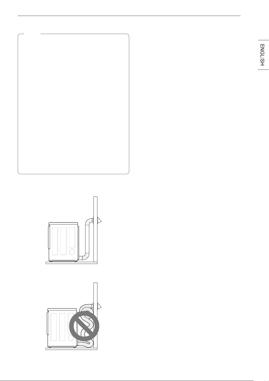
Routing And Connecting Ductwork
NOTE
Follow the guidelines below to maximize drying
performance and reduce lint buildup and
condensation in the ductwork. Ductwork and
fittings are NOT included and must be purchased
separately.
•
Use 4-inch (10.2 cm) diameter rigid, semi-rigid
or flexible metal ductwork.
•
The exhaust duct run should be as short as
possible.
•
Use as few elbow joints as possible.
•
The male end of each section of exhaust duct
must point away from the dryer.
•
Use duct tape on all duct joints.
•
Insulate ductwork that runs through unheated
areas in order to reduce condensation and lint
buildup on duct surfaces.
•
Incorrect or inadequate exhaust systems
are not covered by the dryer warranty. Dryer
failures or service required because of such
exhaust systems will not be covered by the
dryer warranty.
Correct Venting
Incorrect Venting
24
INSTALLATION
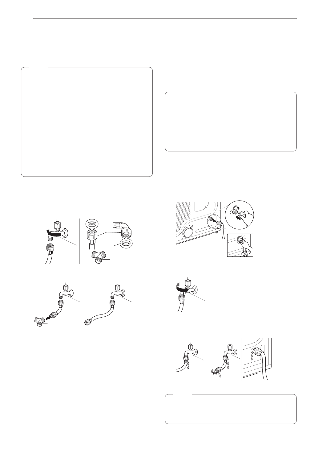
Connecting the Inlet Hose
(Steam Models)
The dryer must be connected to the cold water tap
using a new water supply hose. Do not use old hoses.
NOTE
•
Water supply pressure must be between 20
and 120 psi (138—827 kPa) .
•
Do not strip or cross-thread when connecting
the inlet hose to the valve.
•
If the water supply pressure is more than 800
kPa, a pressure-reducing valve should be
installed.
•
Periodically check the condition of the hose and
replace the hose if necessary.
•
Replace inlet hoses after 5 years of use to
reduce the risk of hose failure.
•
Record hose installation or replacement dates
on the hoses for future reference.
1
Check the rubber seal at each end of the inlet
hoses. Two rubber seals are supplied with each
inlet hose. They are used for preventing water
leaks. Make sure the connection to the cold
water tap is tight.
Hose
connector
Rubber
seal
Y connector
2
Check the installation type.
Y connector
Long
hose
Short
hose
WITH WASHER WITHOUT WASHER
Connect all water supply hoses tightly by hand
and then tighten another 2/3 turn with pliers.
WITH WASHER: When connecting the dryer to the
same faucet as a washer.
a. Shut off the cold water tap and remove the washer
hose.
b. Connect the short hose to the Y-connector using
one of the rubber seals.
c. Connect the other end of the short hose to the cold
water faucet.
d. Connect the long dryer hose to one side of the
Y-connector and connect the washer hose to the
other side.
WITHOUT WASHER: If the dryer does not share
the cold water tap with a washer.
a. Connect the straight end of the long hose to the
cold water faucet.
NOTE
•
Before connecting the water line to the dryer,
flush several gallons of water into a drain or
bucket. This will help prevent foreign particles
such as sand and scale from clogging the dryer
inlet valve.
•
Do not overtighten. Damage to the coupling
may result.
3
Connect the hose to the dryer. Connect the
water supply hose to the dryer inlet valve tightly
by hand and then tighten another 2/3 turn with
pliers.
Make sure that there are no kinks in the hoses
and that they are not crushed.
4
Turn on the cold water faucet.
5
Check for leaks at the Y-connector (if used) and
in all hoses.
NOTE
•
If any leaks are found, shut off the water faucet,
remove the hose and check the condition of the
rubber seal.
25
INSTALLATION
Connecting Gas Dryers
WARNING
To reduce the risk of fire or explosion, electric
shock, property damage, injury to persons, or
death when using this appliance, follow basic
safety precautions.
GasSupplyRequirements
•
As shipped from the factory, this dryer is
configured for use with natural gas (NG). It can
beconvertedforusewithpropane(LP)gas.
Gas pressure must not exceed 8-inch (20.3 cm)
water column for NG, or 13-inch (33 cm) water
column for LP.
•
Aqualifiedserviceorgascompanytechnician
mustconnectthedryertothegasservice.
Failure to follow these instructions may result
in fire, explosion, or death.
•
Isolate the dryer from the gas supply system
byclosingitsindividualmanualshutoffvalve
during any pressure testing of the gas supply at
pressures greater than 1/2 psi (3.5 kPa).
•
Supplylinerequirements:Yourlaundryroom
musthavearigidgassupplylinetoyourdryer.
IntheUnitedStates,anindividualmanual
shutoffvalveMUSTbeinstalledwithinatleast
6 ft. (1.8 m) of the dryer, in accordance with
the National Fuel Gas Code ANSI Z223.1 or
Canadian gas installation code CSA B149.1.
A 1/8-inch (0.3 cm) NPT pipe plug must be
installed.
Failure to do so may result in fire,
explosion, or death.
•
If using a rigid pipe, the rigid pipe should be ½
inch IPS. If acceptable under local codes and
ordinances and when acceptable to your gas
supplier,3/8-inch(1cm)approvedtubingmay
be used where lengths are less than 20 ft. (6.1
m). Larger tubing should be used for lengths
in excess of 20 ft. (6.1 m).
Failure to do so may
result in fire, explosion, or death.
•
Connect the dryer to the type of gas shown on
the nameplate.
Failure to do so may result in fire,
explosion, or death.
•
Topreventcontaminationofthegasvalve,
purge the gas supply of air and sediment before
connecting the gas supply to the dryer. Before
tightening the connection between the gas
supply and the dryer, purge remaining air until
the odor of gas is detected.
Failure to do so may
result in fire, explosion, or death.
•
DO NOT use an open flame to inspect for gas
leaks.Useanoncorrosiveleakdetectionfluid.
Failure to do so may result in fire, explosion, or
death.
•
Use only a new AGA- or CSA-certified gas
supply line (in compliance with the Standard
for Connectors for Gas Appliances, ANSI
Z21.24•CSA6.10)withflexiblestainlesssteel
connectors.
•
Securely tighten all gas connections.
Failure to
do so may result in fire, explosion, or death.
•
Use Teflon tape or a pipe-joint compound
that is insoluble in propane (LP) gas on all
pipe threads.
Failure to do so may result in fire,
explosion, or death.
•
DO NOT attempt any disassembly of the dryer;
disassemblyrequirestheattentionandtoolsof
anauthorizedandqualifiedservicetechnician
or company.
Failure to follow this warning may
result in fire, explosion, or death.
ElectricalRequirementsforGas
Models Only
•
Donot,underanycircumstances,cutorremove
the third (ground) prong from the power cord.
Failure to follow this warning may result in fire,
explosion, or death.
•
For personal safety, this dryer must be properly
grounded.
Failure to follow this warning may result
in fire, explosion, or death.
•
This dryer must be plugged into a 120-VAC, 60-
Hz. grounded outlet protected by a 15-ampere
fuse or circuit breaker.
Failure to follow this
warning may result in fire, explosion, or death.
•
Where a standard 2-prong wall outlet is
encountered, it is your personal responsibility
andobligationtohaveitreplacedwitha
properly grounded 3-prong wall outlet.
Failure to
follow this warning may result in fire, explosion, or
death.
Plug dryer into a
Connection
Gas Supply
Shut
Valve
Plug
AGA/CSA-Cer
Stainless Steel Flexible
Connector
Plug dryer into a 120 VAC,
60 Hz grounded 3-prong
outlet.
WARNING
ELECTRIC SHOCK HAZARD
Failure to follow safety warnings could result in
serious injury or death.
This dryer is equipped with a three-prong
grounding plug for protection against shock
hazard and should be plugged directly into a
properly grounded three-prong receptacle. Do not
cut or remove the grounding prong from this plug.
26
INSTALLATION
Connecting the Gas Supply
•
Installationandservicemustbeperformed
byaqualifiedinstaller,serviceagency,orthe
gas supplier.
Failure to do so may result in fire,
explosion, or death.
•
Use only a new stainless steel flexible
connector and a new AGA-certified connector.
Failure to do so may result in fire, explosion, or
death.
•
Agasshutoffvalvemustbeinstalledwithin6ft.
(1.8 m) of the dryer.
Failure to do so may result in
fire, explosion, or death.
•
The dryer is configured for natural gas when
shipped from the factory. Make sure that the
dryerisequippedwiththecorrectburnernozzle
for the type of gas being used (natural gas or
propane gas).
Failure to do so may result in fire,
explosion, or death.
•
If necessary, the correct nozzle (for the LP
nozzle kit, order part number 383EEL3002D)
shouldbeinstalledbyaqualifiedtechnician
and the change should be noted on the dryer.
Failure to do so may result in fire, explosion, or
death.
•
All connections must be in accordance with
local codes and regulations.
Failure to do so may
result in fire, explosion, or death.
•
Gas dryers MUST exhaust to the outdoors.
Failure to do so may result in fire, explosion, or
death.
NOTE
This dryer is configured from the factory for
natural gas (NG). If the dryer is to be used with
propane (LP) gas, it must be converted by a
qualified service technician.
1
Make sure that the gas supply to the laundry
room is turned OFF and the dryer is unplugged.
Confirm that the type of gas available in your
laundry room is appropriate for the dryer.
2
Remove the shipping cap from the gas fitting at
the back of the dryer. Be careful not to damage
the threads of the gas connector when removing
the shipping cap.
3
Connect the dryer to your laundry room’s gas
supply using a new flexible stainless steel
connector with a 3/8-inch NPT fitting.
NOTE
DO NOT use old connectors.
4
Securely tighten all connections between the
dryer and your laundry room’s gas supply.
5
Turn on your laundry room’s gas supply.
6
Check all pipe connections (both internal and
external) for gas leaks with a noncorrosive leak-
detection fluid.
7
Proceed to Venting the Dryer.
3/8"
NPT gas
Connection
AGA/CSA-Certied
Stainless Steel
Flexible Connector
1/8" NPT Pipe Plug
Gas Supply Shutoff
Valve
High-altitude Installations
The BTU rating of this dryer is AGA-certified for
elevations below 10,000 feet.
If your gas dryer is being installed at an elevation
above 10,000 feet, it must be derated by a qualified
technician or gas supplier.

27
INSTALLATION
Connecting Electric Dryers
ElectricalRequirementsforElectric
Models Only
WARNING
To help prevent fire, electric shock, serious injury,
or death, the wiring and grounding must conform
to the latest edition of the National Electrical
Code, ANSI/NFPA 70 and all applicable local
regulations. Please contact a qualified electrician
to check your home’s wiring and fuses to ensure
that your home has adequate electrical power to
operate the dryer.
•
This dryer must be connected to a grounded
metal, permanent wiring system, or an
equipment-groundingconductormustberun
with the circuit conductors and connected
totheequipment-groundingterminalorlead
on the dryer.
Failure to do so may result in fire,
explosion, or death.
•
The dryer has its own terminal block that must
be connected to a separate 240 VAC, 60-Hertz,
single-phase circuit, fused at 30 amperes (the
circuit must be fused on both sides of the
line). ELECTRICAL SERVICE FOR THE DRYER
SHOULD BE OF THE MAXIMUM RATE VOLTAGE
LISTED ON THE NAMEPLATE. DO NOT
CONNECT THE DRYER TO 110-, 115-, OR 120-
VOLT CIRCUIT.
Failure to follow these instructions
may result in fire, explosion, or death.
•
If the branch circuit to dryer is 15 ft. (4.5
m) or less in length, use UL (Underwriters
Laboratories) listed No.-10 AWG wire (copper
wireonly),orasrequiredbylocalcodes.If
over15ft.(4.5m),useUL-listedNo.-8AWG
wire(copperwireonly),orasrequiredbylocal
codes. Allow sufficient slack in wiring so the
dryercanbemovedfromitsnormallocation
when necessary.
Failure to do so may result in
fire, explosion, or death.
•
The power cord (pigtail) connection between
the wall receptacle and the dryer terminal block
IS NOT supplied with the dryer. Type of pigtail
and gauge of wire must conform to local codes
and with instructions on the following pages.
Failure to follow these instructions may result in
fire, explosion, or death.
•
Do not modify the plug and internal wire provided
with the dryer.
•
The dryer should be connected to a 4-hole outlet.
•
If the plug does not fit the outlet, a proper outlet will
need to be installed by a qualified electrician.
28
INSTALLATION
WARNING
Connect the power cord to the terminal block.
Each colored wire should be connected to the
same color screw. Wire color indicated on manual
is connected to the same color screw in the block.
Failure to follow these instructions may result in a
short or overload.
Grounding through the neutral conductor is
prohibited for: (1) new branch-circuit installations,
(2) areas where local codes prohibit grounding
through the neutral conductor.
Four-Wire Power Cord
•
A UL-listed strain relief is required.
•
Use a 30-amp, 240-volt, 4-wire, UL-
listed power cord with #10 AWG-
minimum copper conductor and closed
loop or forked terminals with upturned
ends.
1
Remove the terminal block access cover on the
upper back of the dryer.
2
Install a UL-listed strain relief into the power cord
through-hole.
3
Thread a 30-amp, 240-volt, 4-wire, UL-listed
power cord with #10 AWG-minimum copper
conductor through the strain relief.
Terminal Block
UL-Listed
Strain Relief
UL-Listed 4-Wire Power Cord
4
Transfer the dryer’s ground wire from behind the
green ground screw to the center screw of the
terminal block.
NOTE
This dryer is supplied with the neutral wire
grounded. This white ground wire MUST BE
MOVED to the neutral terminal when a 4-wire
cord is to be used, or where grounding through
the neutral conductor is prohibited.
5
Attach the two hot leads of the power cord to the
outer terminal block screws.
6
Attach the white neutral wire to the center screw
of the terminal block.
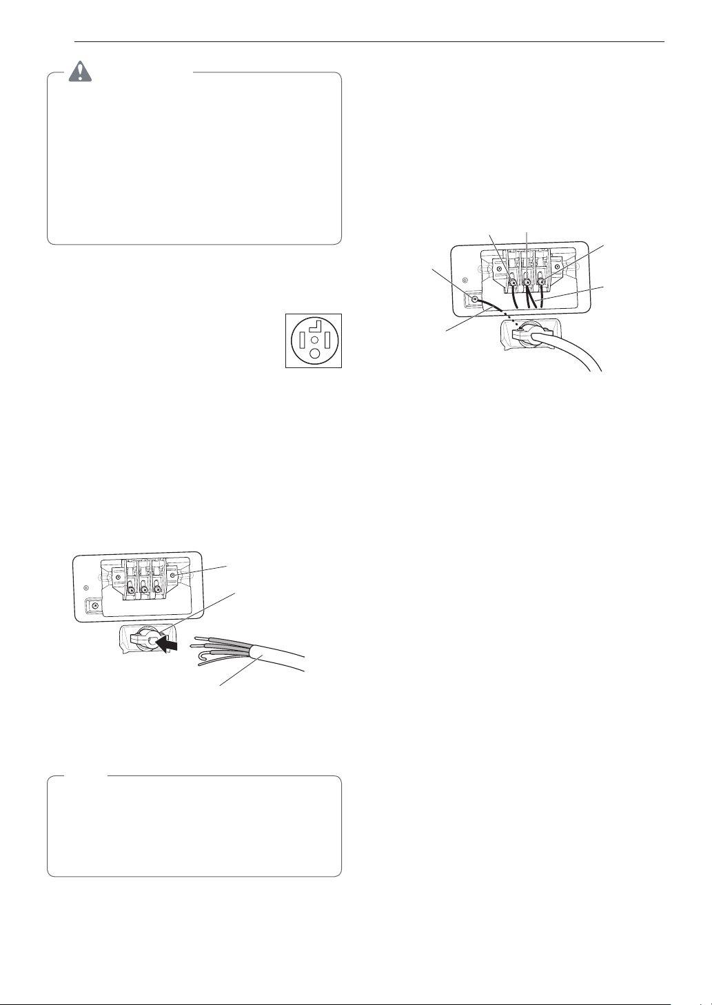
7
Attach the power cord ground wire to the green
ground screw.
8
Tighten all screws securely.
9
Reinstall the terminal block access cover.
Hot
(Red)
Neutral
(White)
Hot
(Black)
Ground
Screw
Power Cord
Ground Wire
White Wire
moved from
Ground
Screw

29
INSTALLATION
Four-Wire Direct Wire
•
A UL-listed strain relief is required.
•
Use UL-listed 4-wire #10 AWG-
minimum copper conductor cable.
Allow at least 5 ft. (1.5 m) of wire to
allow for removal and reinstallation of
the dryer.
1
Remove 5-inch (12.7 cm) of the outer covering
from the wire. Remove 5-inch (12.7 cm)
of insulation from the ground wire. Cut off
approximately 1½-inch (3.8 cm) from the other
three wires and strip 1 inch (2.5 cm) insulation
from each wire. Bend the ends of the three
shorter wires into a hook shape.
Ground Wire
1" (2.5 cm)
5"
(12.7 cm)
2
Remove the terminal block access cover on the
upper back of the dryer.
3
Install a UL-listed strain relief into the power cord
through-hole.
4
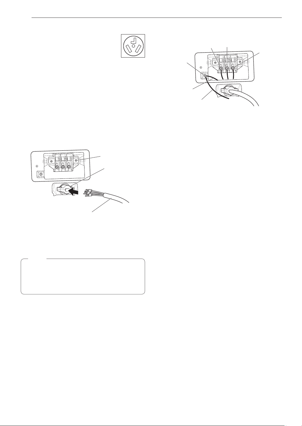
Thread the 4-wire #10 AWG-minimum copper
power cable prepared in step 1 through the
strain relief.
Terminal Block
UL-Listed
Strain Relief
UL-Listed 4-Wire Power Cord
5
Transfer the dryer’s ground wire from behind the
green ground screw to the center screw of the
terminal block.
NOTE
This dryer is supplied with the neutral wire
grounded. This white ground wire MUST BE
MOVED to the neutral terminal when a 4-wire
cord is to be used, or where grounding through
the neutral conductor is prohibited.
6
Attach the two hot leads of the power cord to the
outer terminal block screws.
7
Attach the white neutral wire to the center screw
of the terminal block.
8
Attach the power cord ground wire to the green
ground screw.
9
Tighten all screws securely.
10
Reinstall the terminal block access cover.
Hot
(Red)
Neutral
(White)
Hot
(Black)
Ground
Screw
Power Cord
Ground Wire
White Wire
moved from
Ground
Screw
30
INSTALLATION
Three-Wire Power Cord
•
A 3-wire connection is NOT permitted
on new construction after January 1,
1996.
•
A UL-listed strain relief is required.
•
Use a 30-amp, 240-volt, 3-wire, UL-listed power
cord with #10 AWG-minimum copper conductor and
closed loop or forked terminals with upturned ends.
1
Remove the terminal block access cover on the
upper back of the dryer.
2
Install a UL-listed strain relief into the power cord
through-hole.
3
Thread a 30-amp, 240-volt, 3-wire, UL-listed
power cord with #10 AWG-minimum copper
conductor through the strain relief.
Terminal Block
UL-Listed
Strain Relief
UL-Listed 3-Wire Power Cord
4
Attach the two hot leads (black and red) of the
power cord to the outer terminal block screws.
5
Attach the neutral (white) wire to the center
terminal block screw.
NOTE
The dryer is supplied with the neutral conductor
grounded. If a 3-wire cord is to be used and is
allowed, make sure the white neutral grounding
wire is connected to the green ground screw.
6
Connect the external ground (if required by local
codes) to the green ground screw.
7
Tighten all screws securely.
8
Reinstall the terminal block access cover.
Hot
(Red)
Neutral
(White)
Hot
(Black)
Ground
Screw
External Ground
Wire (If required
by local codes)
White Wire
from Dryer
harness
31
INSTALLATION
Three-Wire Direct Wire
•
A 3-wire connection is NOT permitted
on new construction after January 1,
1996.
•
A UL-listed strain relief is required.
•
Use UL-listed 3-wire, #10 AWG-minimum copper
conductor cable. Allow at least 5 ft. (1.5 m) length
to allow for removal and installation of dryer.
1
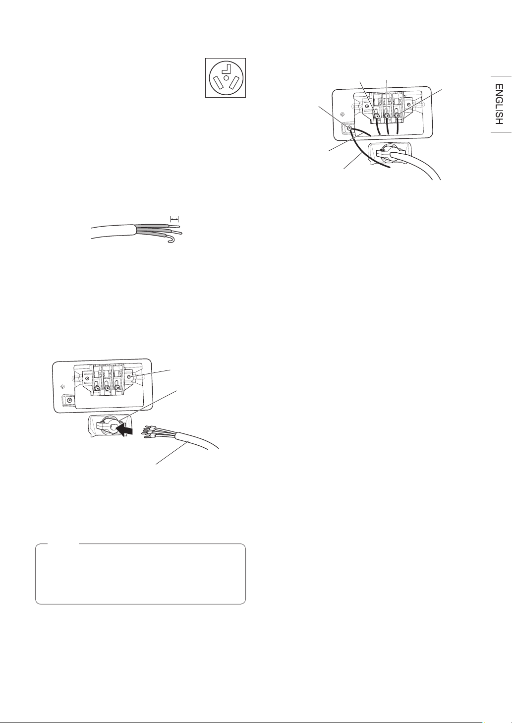
Remove 3½-inch (8.9 cm) of the outer covering
from the wire. Strip 1 inch (2.5 cm) insulation
from each wire. Bend the ends of the three wires
into a hook shape.
1" (2.5 cm)
2
Remove the terminal block access cover on the
upper back of the dryer.
3
Install a UL-listed strain relief into the power cord
through-hole.
4
Thread the 3-wire, #10 AWG-minimum copper
conductor power cable prepared in step 1
through the strain relief.
Terminal
Block
UL-Listed
Strain Relief
UL-Listed 3-Wire Power Cord
5
Attach the two hot leads (black and red) of the
power cord to the outer terminal block screws.
6
Attach the neutral (white) wire to the center
terminal block screw.
NOTE
The dryer is supplied with the neutral conductor
grounded. If a 3-wire cord is to be used and is
allowed, make sure the white neutral grounding
wire is connected to the green ground screw.
7
Connect the external ground (if required by local
codes) to the green ground screw.
8
Tighten all screws securely.
9
Reinstall the terminal block access cover.
Hot
(Red)
Neutral
(White)
Hot
(Black)
Ground
Screw
External Ground
Wire (If required by
local codes)
White Wire
from Dryer
harness
Final Installation Check
Once you have completed the installation of the dryer
and it is in its final location, confirm proper operation
with the following tests and Installation Test (Duct
Check) on the following page.
Testing Dryer Heating
GAS MODELS
Close the dryer door, press the
POWER
button to turn
the dryer on, and start the dryer on a heat setting.
When the dryer starts, the igniter should ignite the
main burner.
ELECTRIC MODELS
Close the dryer door, press the
POWER
button to turn
the dryer on, and start the dryer on a heat setting.
The exhaust air should be warm after the dryer has
been operating for 3 minutes.
CheckingAirow
Effective dryer operation requires proper airflow.
The adequacy of the airflow can be measured by
evaluating the static pressure. Static pressure in the
exhaust duct can be measured with a manometer,
placed on the exhaust duct approximately 2 ft. (60.9
cm) from the dryer. Static pressure in the exhaust duct
should not exceed 0.6-inch (1.5 cm). The dryer should
be checked while the dryer is running with no load.
CheckingLevelness
Once the dryer is in its final location, recheck the
dryer to be sure it is level. Make sure it is level front
to back and side to side, and that all four leveling feet
are firmly on the floor.
32
INSTALLATION
Installation Test (Duct Check)
Once you have completed the installation of the
dryer, use this test to make sure the condition of the
exhaust system is adequate for proper operation of
the dryer. This test should be performed to alert you
to any serious problems in the exhaust system of
your home.
•
Your dryer features Flow Sense™, an innovative
sensing system that automatically detects
blockages and restrictions in dryer ductwork.
Keeping ductwork clean of lint buildup and free of
restrictions allows clothes to dry faster and reduces
energy use.
NOTE
The dryer should be cool before starting this test.
If the dryer was warmed up during installation, run
the AIR DRY cycle for a few minutes to reduce
the interior temperature.
Toactivatetheinstallationtest:
1
Removethedryingrackandliterature,and
then close the door.
Do not load anything in the drum for this test, as
in may affect the accuracy of the results.
2
After you are pressed of Power button, you
will press and hold the Temp. and Signal
buttons in 3 seconds.
This button sequence activates the installation
test. The code will display if the activation
is successful.
3
Press the START/PAUSE button.
The dryer will start the test, which will last about
2 minutes. The heat will be turned on and the
temperatures in the drum will be measured.
4
Check the display for results.
During the test cycle, monitor the Flow Sense™
display on the control panel. If no bars are
displayed, when the cycle ends, the exhaust
system is adequate. If the exhaust system is
severely restricted, the display will show four
bars. Other problems may also be shown with
error codes. Refer to the next page for error
code details and solutions.
NO BARS:
OK
FOUR BARS:
RESTRICTED
Four bars indicates that the exhaust system is
severely restricted. Have the system checked
immediately, as performance will be poor.
5
End of cycle.
At the end of the test cycle, will display.
The test cycle will end and the dryer will shut off
automatically after a short delay.
•
Checktheerrorcodebeforeyoucallforservice
Error
Code
Possible
Causes
Solutions
tE1 or
tE2
•
Temperature
sensor failure.
•
Turn off the dryer and
call for service.
HS
•
Humidity
sensor failure.
•
Turn off the dryer and
call for service.
PS or
PF or
nP
•
Electric dryer
power cord is
not connected
correctly, or
house power
supply is
incorrect.
•
House fuse is
blown, circuit
breaker has
tripped, or
power outage
has occurred.
•
Check the power
supply or the
connection of the
power cord to the
terminal block. Refer
to the
Connecting
Electric Dryers
section of this
manual for complete
instructions.
•
Reset circuit breaker
or replace fuse. Do
not increase the fuse
capacity.
If the problem is a
circuit overload, have it
corrected by a qualified
electrician.
gAS
•
Gas supply or
service turned
off. (Gas
Model only.)
•
Confirm that house
gas shutoff and the
dryer gas shutoff are
both fully open.
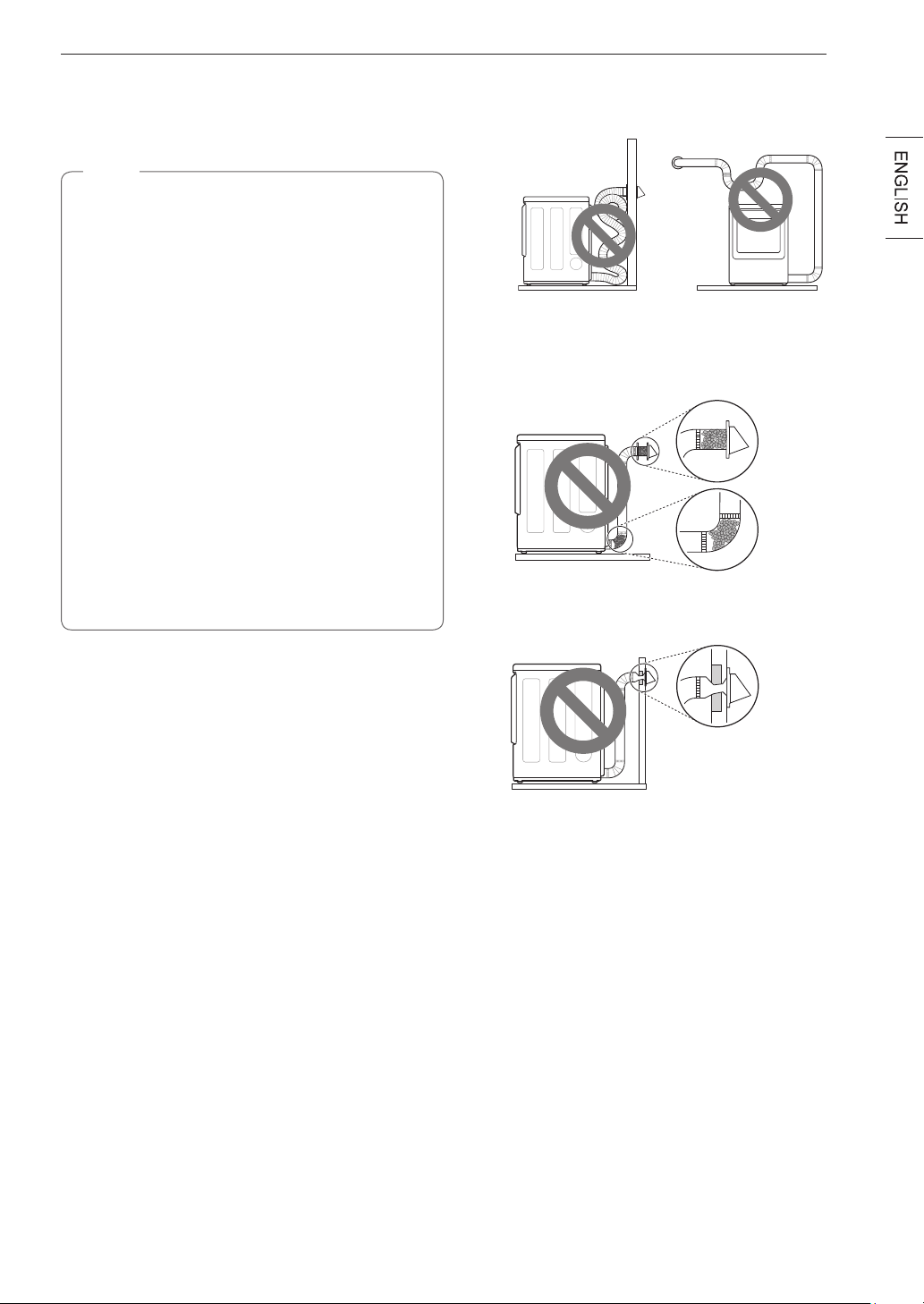
33
INSTALLATION
•
Check the duct condition
If the Flow Sense
TM
LED is turned on, check the
exhaust system for restrictions and damage. Repair
or replace the exhaust system as needed.
NOTE
When the dryer is rst installed, this test should
be performed to alert you to any existing
problems with the exhaust duct in your home.
However, since the test performed during normal
operation provides more accurate information on
the condition of the exhaust duct than does the
installation test, the number of bars displayed
during the two tests may not be the same.
Do not interrupt the test cycle, as this could result
in inaccurate results.
Even if no bars are displayed during the test
cycle, some restrictions may still be present in the
exhaust system. Refer to the Venting the Dryer
section of this manual for complete exhaust
system and venting requirements.
Your dryer features Flow Sense™, an innovative
sensing system that automatically detects
blockages and restrictions in the dryer ductwork.
Keeping ductwork clean of lint buildup and free
of restrictions allows clothes to dry faster and
reduces energy use.
RestrictedorBlockedAirow
Avoid long runs or runs with multiple elbows or bends.
Excess or crushed
transition duct
Too many elbows or
exhaust too long
Check for blockages and lint buildup.
Lint
buildup or
blockage
Make sure the ductwork is not crushed or restricted.
Crushed
or
damaged
exhaust
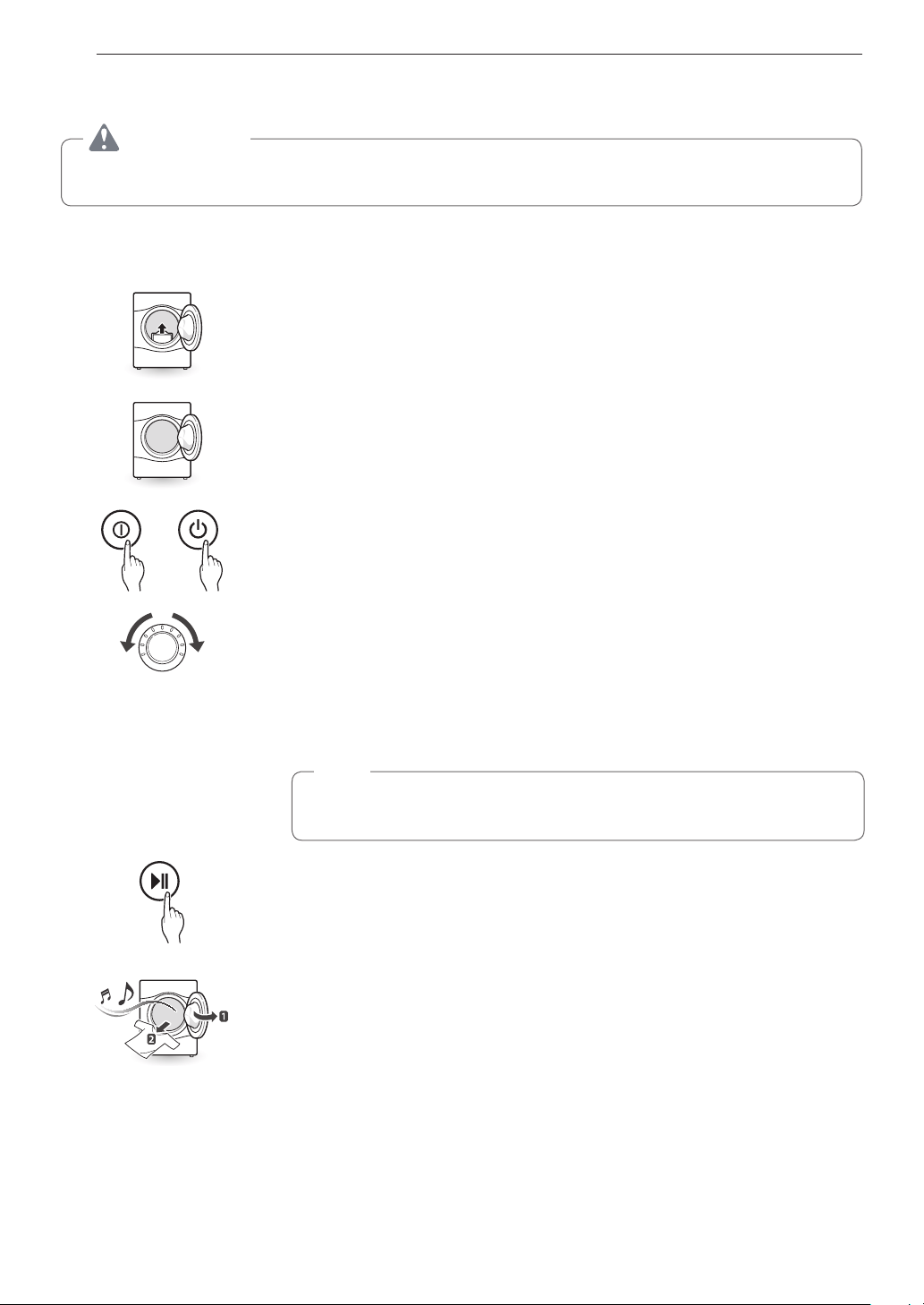
34
OPERATION
OPERATION
WARNING
To reduce the risk of fire, electric shock, or injury to persons, read this entire manual, including the
IMPORTANT SAFETY INSTRUCTIONS, before operating this dryer.
Using the Dryer
1 Clean the Lint Filter
If the lint filter has not already been cleaned, lift out the filter and remove the lint
from the last load. This will help ensure the fastest and most efficient drying perfor-
mance. Make sure to reinstall the filter, pressing down until it clicks firmly into place.
The dryer will not operate without the lint filter in place.
2 Load the Dryer
Load the dryer with the wet laundry from the washer. If the load is extra large,
you may need to divide it into smaller loads for proper performance and fabric
care.
3 Turn on The Dryer
Press the POWER button to turn ON the dryer. The cycle LEDs will illuminate and a
chime will sound.
4 Select a Cycle
Turn the cycle selector knob either direction until the LED for the desired cycle
is on. The preset temperature, dry level, and option settings for that cycle will
be shown. Refer to page 37. Default settings for the selected cycle can now be
changed if desired. This can be done using the cycle modifier buttons as shown
on page 37. Cycle options can be added using the option buttons as shown on
page 38-41.
NOTE
Not all options or modifiers are available on all cycles. A different chime will
sound and the LED will not come on if the selection is not allowed.
5 Begin the Cycle
Press the
START/PAUSE
button to begin the cycle. The cycle can be paused at
any time either by opening the door or by pressing the
START/PAUSE
button.
If the cycle is not restarted within 4 minutes of being paused, the dryer will shut off
and the settings will be lost.
Lint
Filter
6 End of Cycle
When the cycle is finished, the chime will sound. Immediately remove your
clothing from the dryer to reduce wrinkling. If Wrinkle Care is selected, the dryer
will tumble briefly every few minutes to help prevent wrinkles from setting in the
clothes.
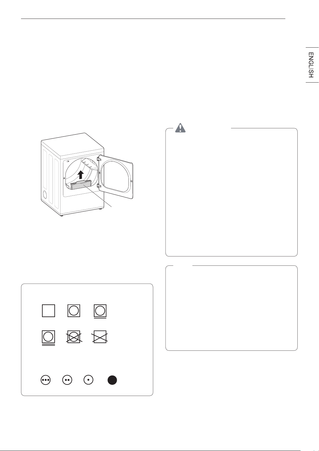
35
OPERATION
Check the Lint Filter Before
EveryLoad
Always make sure the lint filter is clean before starting
a new load; a clogged lint filter will increase drying
time. To clean, pull the lint filter straight up and roll
any lint off the filter with your fingers. Do not rinse or
wash the filter to remove lint. Push the lint filter firmly
back into place. See
Regular Cleaning
for more
information.
Always ensure the lint filter is properly installed before
running the dryer. Running the dryer with a loose or
missing lint filter will damage the dryer and articles in
the dryer.
Lint Filter
Sorting Loads
Fabric Care Labels
Most articles of clothing feature fabric care labels that
include instructions for proper care.
Fabric Care Labels
Heat setting
High
Medium Low
No heat/air
Tumble dry
Dry
Normal
Permanent Press/
wrinkle resistant
Gentle/
delicate
Do not
tumble dry
Do not dry
(used with do not wash)
Group Similar Items
For best results, sort clothes into loads that can be
dried with the same drying cycle.
Different fabrics have different care requirements, and
some fabrics will dry more quickly than others. For
best fabric care results, always dry fabrics with similar
care requirements together.
Loading the Dryer
WARNING
To reduce the risk of fire, electric shock, or
injury to persons when using this appliance,
follow basic precautions, including the
following:
•
Check all pockets to make sure that they are
empty. Items such as clips, pens, coins, and
keys can damage both your dryer and your
clothes. Flammable objects such as lighters
or matches could ignite, causing a fire.
Failure to do so may result in fire, explosion, or
death.
•
Neverdryclothesthathavebeenexposed
to oil, gasoline, or other flammable
substances. Washing clothes will not
completelyremoveoilresidues. Failure to
obey this warning may result in fire, explosion,
or death.
NOTE
Loading Tips
•
Combine large and small items in the same
load.
•
Damp clothes will expand as they dry. Do not
overload the dryer; clothes require room to
tumble and dry properly.
•
Use mesh laundry bags to separate clothes
with zippers, hooks, straps, and drawstrings to
prevent them from catching on or tangling with
other clothes or damaging the lint filter.
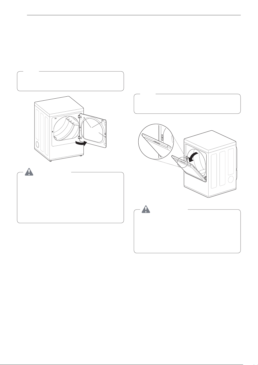
36
OPERATION
Using the LG EasyLoad
TM
Swing Door
Use the swing door when unloading, or when loading
bulkier items, for easy access to the drum.
To open the swing door, grasp the top of the door on
the side opposite the hinge and pull.
NOTE
Make sure the hamper door release is completely
closed before using the swing door.
Swing door
Interlock
Buttons
WARNING
Do not press the three interlock buttons when
the door is open. The door may fall off and cause
serious injury.
•
Donotplaceheavyitemsonorleanagainst
the top of the door when it is open.
The dryer could tip forward, causing injury or
propert damage.
Hamper Door (on some models)
Use the hamper door when loading. The hamper door
opens about 40 degrees and acts as a chute to help
guide items into the drum and help prevent items from
falling onto the floor. It also comes in handy when
unloading a few small items, helping prevent the rest
of the laundry from being pulled onto the floor.
To open the hamper door, press the release on the
top of the door and pull the door forward.
Make sure laundry is fully inserted in the drum before
closing the door.
NOTE
Make sure the swing door latch is completely
closed before pressing the hamper door release.
Hamper door release
40°
Hamper door
WARNING
•
Do not attempt to pull the hamper door open
more than 40 degrees.
•
Be careful when opening and closing the door.
Fingers and hands can get caught in the door
and cause injury if the door drops forward
unexpectedly.
37
OPERATION
Control Panel
1 2 3 5 64
8 47
NOTE
Model numbers can be found on the cabinet inside the door.
1
POWER Button
Press to turn the dryer ON. Press again to turn the
dryer OFF.
NOTE
Pressing the POWER button during a cycle will
cancel that cycle and any load settings will be
lost.
2
Cycle Selector Knob
Turn this knob to select the desired cycle. Once
the desired cycle has been selected, the standard
presets are shown in the display. On Manual Dry
cycles, these settings can be adjusted using the cycle
modifier buttons any time before starting the cycle.
3
START/PAUSE Button
Press this button to start the selected cycle. If the
dryer is running, use this button to pause the cycle
without losing the current settings.
NOTE
If you do not press the START/PAUSE button to
resume a cycle within 60 minutes, the dryer turns
off automatically.
4
Cycle option Buttons
The option buttons allow you to select additional cycle
options. Certain buttons also allow you to activate
special functions by pressing and holding the button
for 3 seconds.
5
Time and Status Display
The display shows the settings, estimated time
remaining, options, and status messages for your
dryer.
6
MORE TIME/LESS TIME Buttons
Use these buttons with the Time Dry and other
MANUAL DRY cycles to adjust the drying time.
Press the
More Time
button to increase the selected
manual cycle time by 5 minutes; press the
Less Time
button to decrease the cycle time by 5 minutes.
7
Cycle Modifier Buttons
Use these buttons to select the desired cycle settings
for the selected cycle. The current settings are shown
in the display. Press the button for that option to
select other settings.
8
Steam Functions
LG’s steam technology allows you to inject fabrics
with a swirling jet of steam to refresh clothes, reduce
static, and make ironing easier. Simply select the
Steam Fresh™
cycle or
Steam Sanitary ™
cycle or
you can add a Steam option to selected cycles.

38
OPERATION
9 1210 11
1314
9
Control Lock Indicator
When Control Lock is set, the Control Lock indicator
appears and all buttons are disabled except the
POWER
button. This prevents children from changing
settings while the dryer is operating.
10
Flow Sense
™
Duct Blockage Sensing System
Indicator
The Flow Sense™ duct blockage sensing system
detects and alerts you to blockages in the ductwork
that reduce exhaust flow from the dryer. Maintaining
a clean exhaust system improves operating efficiency
and helps minimize service calls, saving you money.
11
Clean Filter Reminder
The display will show Clean Filter when the dryer is
turned on as a reminder to check the filter. It turns off
when the
START/PAUSE
button is pressed.
12
Cycle Completion Indicator
This portion of the display shows which stage of the
drying cycle is currently underway (Dry, Cool).
13
Estimated Time Remaining
This display shows the estimated time remaining for
SENSOR DRY cycles or the actual time remaining for
Time Dry or MANUAL DRY cycles.
NOTE
The cycle time on SENSOR DRY cycles may
fluctuate as the dryer recalculates drying time for
optimal results.
14
Wi-Fi Indicator
When the appliance is connected to the internet
through a home Wi-Fi network, this indicator appears.
39
OPERATION
Cycle Guide
Cycle Fabric Type DryLevel Temp.
More
Time/
Less
Time
Wrinkle
Care
Turbo
Steam
Damp
Dry
Signal
Reduce
Static
Energy
Saver
Steam
Fresh
TM
Comforter, Shirts,Trousers
(except especially delicate
fabrics)
Off
Med.
High
Adjustable
Steam
Sanitary
TM
Comforter, Bedding,
Children’s clothing
Off High
Anti-
Bacterial
Do not use this cycle with
delicate fabrics.
Very Dry High
Small Load
Only Normal & Cotton/
Towels Fabric Type
(Max 3 lb)
Normal Dry
High
Adjustable
Bedding Comforters, Pillows, Shirts
Normal Dry
Medium
Adjustable
Heavy
Duty
Jeans, heavyweight items
Normal Dry
High
Adjustable
Normal
Work clothes, corduroys,
etc.
Normal Dry
Med.
High
Adjustable
Perm.
Press
Permanent press, synthetic
items
Normal Dry
Medium
Adjustable
Towels
Denims, towels, heavy
cottons
Normal Dry
Med.
High
Adjustable
Sportswear Sports Wear Off -
Delicates Lingerie, sheets, blouses
Normal Dry
Low
Adjustable
Speed Dry
For small loads with short
drying times
Off
High
Adjustable
Air Dry
For items that require heat-
free drying such as plastics
or rubber
Off No Heat
= default setting
= allowable option

40
OPERATION
Sensor Dry Cycles
Sensor dry cycles utilize LG’s unique dual sensor
system to detect and compare the moisture level
in clothes and in the air and adjust the drying time
as needed to ensure superior results. The dryer
automatically sets the dryness level and temperature
at the recommended setting for each cycle. The
estimated time remaining will be shown in the display.
NOTE
To protect your garments not every dryness level,
temperature, or option is available with every
cycle. See the Cycle Guide for details.
Manual Dry Cycles
Use manual dry cycles to select a specific amount
of drying time and a drying temperature. When a
manual dry cycle is selected, the Estimated Time
Remainng display shows the actual time remaining
in your cycle. You can change the actual time in the
cycle by pressing More Time or Less Time.

41
OPERATION
Cycle Settings and Options
CycleModierButtons
SENSOR DRY cycles have preset settings that
are selected automatically. MANUAL DRY cycles
have default settings, but you may also customize
the settings using the cycle modifier buttons. Press
the button for that option to view and select other
settings.
DryLevel
Selects the level of dryness for the cycle. Press
the
DryLevel
button repeatedly to scroll through
available settings.
•
This option is only available with SENSOR DRY
cycles.
•
The dryer will automatically adjust the cycle time.
Selecting More or Very will increase the cycle time,
while Less or Damp will decrease the cycle time.
•
Use a Less Dry or Damp Dry setting for items that
you wish to iron.
Temp.
Adjusts the temperature setting. This allows precise
care of your fabrics and garments. Press the
Temp.
button repeatedly to scroll through available settings.
Time Dry
Allows you to manually select the drying time, from 20
to 60 minutes, in 10-minute increments. Use this for
small loads or to remove wrinkles.
Signal
Press the
Signal
button repeatedly to change the
volume or turn on/off the button tones and the end of
cycle melody.
Cycle Option Buttons
The dryer features several additional cycle options to
customize cycles to meet individual needs. Certain
option buttons also feature a special function that
can be activated by pressing and holding that option
button for 3 seconds. (See Special Functions on the
following page for details.)
Adding Cycle Options to a Cycle:
1
Turn on the dryer and turn the Cycle Selector
Knob to select the desired cycle.
2
Use the cycle modifier buttons to adjust the
settings for that cycle.
3
Press the cycle option button(s) for the option
you would like to add. A confirmation message is
shown in the display.
4
Press the
START/PAUSE
button to start the
cycle. The dryer starts automatically.
Wrinkle Care
Selecting this option will tumble the load periodically
for up to 3 hours after the selected cycle, or until the
door is opened. This is helpful in preventing wrinkles
when you are unable to remove items from the dryer
immediately.
Damp Dry Signal
With this option, the dryer will signal when the load
is approximately 80% dry. This allows you to remove
faster- drying lightweight items or items that you
would like to iron or hang while still slightly damp.
EnergySaver(onsomemodels)
This option helps to reduce energy consumption in
the Normal cycle, depending on the load size.
When the Energy Saver option is selected, the cycle
begins with an air dry section and the drying time is
increased.
NOTE
The Energy Saver option is turned on by default in
the Normal cycle. Turn off the Energy Saver option
for a faster Normal cycle which begins with heated
drying.

42
OPERATION
Special Functions
Some cycle option buttons also activate secondary
functions. These special functions are marked with an
asterisk (*). Press and hold the option button marked
with the special function to activate it.
* Drum Light
The drum is equipped with a blue LED that illuminates
when the dryer is turned on. This light automatically
turns off when the door is closed and the cycle starts.
To turn on the light during a cycle, press and hold the
Wrinkle Care button for three seconds. The drum light
will illuminate and then turn off automatically after four
minutes.
* Control Lock
Use this option to prevent unwanted use of the dryer
or to keep cycle settings from being changed while
the dryer is operating.
Press and hold the button marked
Control Lock
for
3 seconds to activate or deactivate the Control Lock
function. The Control Lock icon will be shown in the
display, and all controls will be disabled except the
POWER
button.
NOTE
Once set, Control Lock remains active until it is
manually deactivated. Control Lock must be turned
off to run another cycle. To deactivate Control
Lock, press and hold the Control Lock button for 3
seconds.
* Default On/Off
This option allows the Energy Saver settings to be
changed. To run a Normal cycle without the Energy
Saver option, press and hold the Energy Saver button
for three seconds. ON or OFF appears in the display.
43
OPERATION
Steam Functions
LG’s new steam technology allows you to inject
fabrics with a swirling jet of hot steam to refresh
clothes and reduce static, or sanitize clothes.
Simply select the Steam Fresh™ cycle or the Steam
Sanitary™ cycle. Or you can add a steam option to
selected cycles.
Using the Steam Fresh™ cycle
Steam Fresh™ uses the power of steam alone to
quickly reduce wrinkles and odors in fabrics. It brings
new life to wrinkled clothes that have been stored for
an extended time. Steam Fresh™ can also be used
to help reduce odors and remove the hanger creases
in fabrics.
NOTE
•
Depending on the load size, change the cycle time
by pressing More Time or Less Time. The display
shows 1, 3, 5, or
. Select 3 for up to three
items; select 5 for four or five items; and select
for a large load, a bulky item like a blanket,
or to remove hanger creases.
To use the Steam Fresh™ cycle:
1
Turn on the dryer and turn the cycle selector
knob to select the Steam Fresh™ cycle.
2
To add an option function, select Wrinkle Care.
3
Depending on the load (quantity of items), steam
time can be changed by pressing the More Time
or Less Time buttons.
4
Press Start/Pause button to start the cycle.
Using the Steam Sanitary™ cycle
The new Steam Sanitary™ cycle is ideal for sanitizing
non-washable items quickly and easily using the
power of steam alone. This cycle is recommended for
use with cotton and polyester materials. (Do NOT use
for urethane foam, down feathers or delicate items.)
Using the Steam Option
The Reduce Static option injects steam late in the
drying cycle to reduce the static electricity caused
by dry fabrics rubbing together. Change the amount
of time for the cycle by pressing the More Time or
Less Time button, depending on the load (quantity
of items). The display will show the recommended
number of items, such as 7, 9, 11, 14, 16, or 18.
TurboSteam helps prevent the overdrying of clothes
by injecting steam during the drying process.
NOTE
•
When Sensor Dry is selected with the Reduce
Static or Turbo Steam option, a Dry level of Less
or Damp cannot be selected.
•
The Reduce Static option may also be selected
during Time Dry cycles.
•
After the Steam option is selected in Time Dry, the
More Time or Less Time buttons will change the
steam time only.
•
After pressing Start/Pause, the More Time or Less
Time buttons will be disabled.
To add steam to a standard cycle:
1
Turn on the dryer and turn the cycle selector
knob to select the desired cycle.
2
Use the cycle setting buttons to adjust the
settings for that cycle.
3
Press the steam option button for the steam
option you would like to add. Then adjust for
the load size using the More Time or Less Time
buttons.
4
Press Start/Pause to start the cycle.

44
OPERATION
WARNING
•
Do not open the dryer door during steam
cycles. Failure to follow this warning can cause
serious injury or death.
•
Do not fill the steam feeder with gasoline,
drycleaningsolvents,orotherflammableor
explosivesubstances. Failure to do so can
result in death, explosion, fire, or burns.
•
Do not touch the steam nozzle in the drum
during or after the steam cycle. Failure to
follow this warning can cause serious injury or
death.
NOTE
•
When Sensor Dry is selected with the Reduce
Static or Turbo Steam option, a dry level of Less
or Damp cannot be selected.
•
The Reduce Static option may also be selected
during Time Dry cycles.
•
After the steam option is selected in Time Dry, the
More Time or Less Time buttons will change the
steam time only.
•
After pressing Start/Pause, the More Time or Less
Time buttons will be disabled.
Steam Cycle Guide
Steam Default Time
Temp.
Control
DryLevel
Fabric
State
Fabric Type
Maximum
Amount
Steam
Sanitary™
31 minutes Dry
Comforter
Bedding
Single (1 each)
Children’s
clothing
3 lbs.
Steam
Fresh™
10 minutes Dry
Comforter Single (1 each)
Shirts* 5 each
Steam
Option
+
Reduce
Static
Follows
Selected
Cycle
Wet
Varies by
selected cycle
8 lbs.
(18 Items.)
+
Turbo
Steam
Wet
Varies by
selected cycle
8 lbs.
(18 Items)
Time Dry
+
Reduce
Static
38 minutes Wet
Varies by
selected cycle
8 lbs.
(18 Items.)
*Shirt: 70% cotton:30% poly blend. Except especially delicate fabrics.
•
When the lint filter or exhaust duct is clogged, steam options will not give proper results.
•
For best results, load articles of similar size and fabric type. Do not overload.
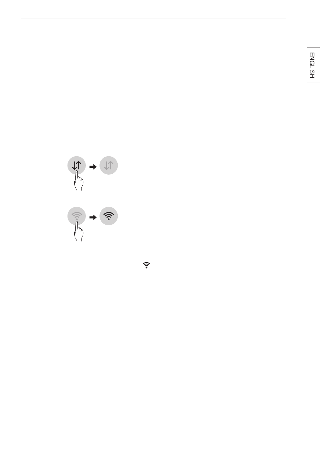
45
SMART FUNCTIONS
SMART FUNCTIONS
LG ThinQ Application
The LG ThinQ application allows you to communicate
with the appliance using a smartphone.
Before Using LG ThinQ
1
Use a smartphone to check the strength of
the wireless router (Wi-Fi network) near the
appliance.
•
If the distance between the appliance and the
wireless router is too far, the signal strength
becomes weak. It may take a long time to
register or installation may fail.
2
Turn off the Mobile data or Cellular Data on
your smartphone.
3
Connect your smartphone to the wireless router.
NOTE
• To verify the Wi-Fi connection, check that Wi-Fi
icon on the control panel is lit.
• The appliance supports 2.4 GHz Wi-Fi networks
only. To check your network frequency, contact your
Internet service provider or refer to your wireless
router manual.
• LG ThinQ is not responsible for any network
connection problems or any faults, malfunctions, or
errors caused by network connection.
• The surrounding wireless environment can make
the wireless network service run slowly.
• If the appliance is having trouble connecting to the
Wi-Fi network, it may be too far from the router.
Purchase a Wi-Fi repeater (range extender) to
improve the Wi-Fi signal strength.
• The network connection may not work properly
depending on the Internet service provider.
• The Wi-Fi connection may not connect or may
be interrupted because of the home network
environment.
• If the appliance cannot be registered due to
problems with the wireless signal transmission,
unplug the appliance and wait about a minute
before trying again.
• If the firewall on your wireless router is enabled,
disable the firewall or add an exception to it.
• The wireless network name (SSID) should be a
combination of English letters and numbers. (Do not
use special characters.)
• Smartphone user interface (UI) may vary depending
on the mobile operating system (OS) and the
manufacturer.
• If the security protocol of the router is set to WEP,
network setup may fail. Change the security
protocol (WPA2 is recommended), and register the
product again.
Installing the LG ThinQ Application
Search for the LG ThinQ application from the Google
Play Store or Apple App Store on a smart phone.
Follow instructions to download and install the
application.

46
SMART FUNCTIONS
LG ThinQ Application Features
Dryer Cycle
Download new and specialized cycles that are not
included in the standard cycles on the appliance.
Appliances that have been successfully registered
can download a variety of specialty cycles specific to
the appliance.
Only one cycle can be stored on the appliance at a
time.
Once cycle download is completed in the appliance,
the appliance keeps the downloaded cycle until a
new cycle is downloaded
Venting Tips
Provides venting tips.
Smart Diagnosis™
This function provides useful information for
diagnosing and solving issues with the appliance
based on the pattern of use.
Energy Monitoring
The dryer energy usage is affected by the cycles and
options so you may see some changes in energy
usage from one cycle to another.
Push Alerts
When the cycle is complete or the appliance has
problems, you have the option of receiving push
notifications on a smart phone.
Settings
Set the product nickname and delete product.
NOTE
• To verify the Wi-Fi connection, check that Wi-Fi
icon on the control panel is lit.
• LG ThinQ is not responsible for any network
connection problems or any faults, malfunctions, or
errors caused by network connection.
• The machine supports 2.4 GHz Wi-Fi networks only.
• If the appliance is having trouble connecting to the
Wi-Fi network, it may be too far from the router.
Purchase a Wi-Fi repeater (range extender) to
improve the Wi-Fi signal strength.
• The Wi-Fi connection may not connect or may
be interrupted because of the home network
environment.
• The network connection may not work properly
depending on the internet service provider.
• The surrounding wireless environment can make
the wireless network service run slowly.
• This information is current at the time of publication.
The application is subject to change for product
improvement purposes without notice to users.
Using Remote Start
Use a smart phone to control the appliance remotely
or check to see how much time is left in the cycle.
1
Press the Power button.
2
Load the laundry.
3
Press and hold the Remote Start button for 3
seconds to enable the Remote Start function.
4
Start a cycle from the LG ThinQ application on
your smart phone.
NOTE
• Once the Remote Start mode is enabled, you
can start a cycle from the LG ThinQ smartphone
application. If the cycle is not started, the machine
will wait to start the cycle until it is turned off
remotely from the application or the Remote Start
mode is disabled.
• If the door is opened, Remote Start is disabled.
Disabling Remote Start
When the Remote Start is activated, press and hold
the Remote Start button for 3 seconds.

47
SMART FUNCTIONS
Wireless LAN Module Specifications
FrequencyRange 2412 MHz to 2462 MHz
Output
Power (Max)
IEEE 802.11b: 22.44 dBm
IEEE 802.11g: 24.68 dBm
IEEE 802.11n: 24.11 dBm
FCC Notice (For transmitter module
contained in this product)
This equipment has been tested and found to comply
with the limits for a Class B digital device, pursuant
to Part 15 of the FCC Rules. These limits are
designed to provide reasonable protection against
harmful interference in a residential installation. This
equipment generates, uses, and can radiate radio
frequency energy and, if not installed and used in
accordance with the instructions, may cause harmful
interference to radio communications. However, there
is no guarantee that interference will not occur in a
particular installation. If this equipment does cause
harmful interference to radio or television reception,
which can be determined by turning the equipment
off and on, the user is encouraged to try to correct
the interference by one or more of the following
measures:
• Reorient or relocate the receiving antenna.
• Increase the separation between the equipment and
the receiver.
• Connect the equipment to an outlet on a circuit
different from that to which the receiver is
connected.
• Consult the dealer or an experienced radio/TV
technician for help.
This device complies with part 15 of the FCC Rules.
Operation is subject to the following two conditions:
1) This device may not cause harmful interference
and
2) This device must accept any interference received,
including interference that may cause undesired
operation of the device.
Any changes or modifications in construction of this
device which are not expressly approved by the party
responsible for compliance could void the user’s
authority to operate the equipment.
FCC RF Radiation Exposure Statement
This equipment complies with FCC radiation
exposure limits set forth for an uncontrolled
environment. This transmitter must not be co-located
or operating in conjunction with any other antenna or
transmitter.
This equipment should be installed and operated with
a minimum distance of 20 cm (7.8 inches) between
the antenna and your body. Users must follow the
specific operating instructions for satisfying RF
exposure compliance.
Open Source Software Notice
Information
To obtain the source code under GPL, LGPL, MPL,
and other open source licenses, that is contained in
this product, please visit http://opensource.lge.com.
In addition to the source code, all referred license
terms, warranty disclaimers and copyright notices are
available for download.
LG Electronics will also provide open source code
to you on CD-ROM for a charge covering the cost
of performing such distribution (such as the cost of
media, shipping, and handling) upon email request
to [email protected]. This offer is valid for three
(3) years from the date on which you purchased the
product.
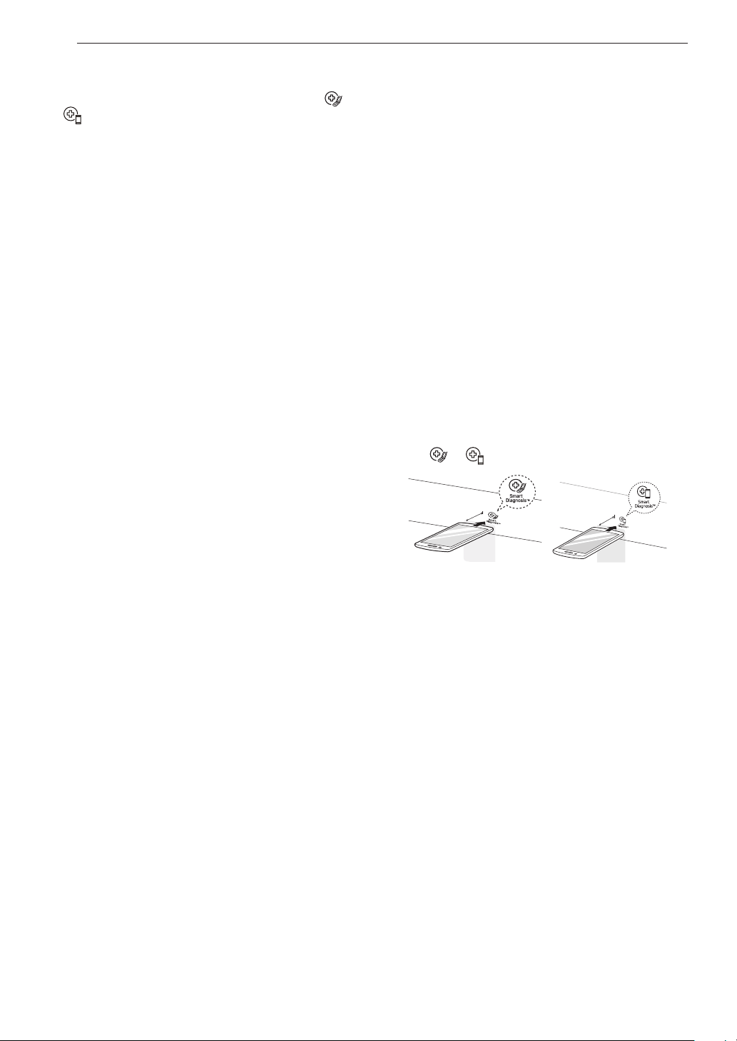
48
SMART FUNCTIONS
Smart Diagnosis
This feature is only available on models with the
or logo.
Use this feature to help you diagnose and solve
problems with your appliance.
NOTE
• For reasons not attributable to LGE’s negligence,
the service may not operate due to external factors
such as, but not limited to, Wi-Fi unavailability,
Wi-Fi disconnection, local app store policy, or app
unavailability.
• The feature may be subject to change without prior
notice and may have a different form depending on
where you are located.
Using LG ThinQ to Diagnose Issues
If you experience a problem with your Wi-Fi
equipped appliance, it can transmit troubleshooting
data to a smartphone using the LG ThinQ
application.
• Launch the LG ThinQ application and select the
Smart Diagnosis™ feature in the menu. Follow the
instructions provided in the LG ThinQ application.
Using Audible Diagnosis to Diagnose
Issues
Follow the instructions below to use the audible
diagnosis method.
• Launch the LG ThinQ application and select the
Smart Diagnosis™ feature in the menu. Follow the
instructions for audible diagnosis provided in the LG
ThinQ application.
1
Press the Power button to turn on the appliance.
• Do not press any other buttons.
2
Hold the mouthpiece of your phone in front of
the or logo.
Max.
10 mm
Max.
10 mm
3
Press and hold the Temp. button for 3 seconds
or longer while continuing to hold your phone
near the logo.
4
Keep the phone in place untill the tone
transmission has finished. The display will count
down the time. Once the count down is over and
the tones have stopped, the diagnosis will be
displayed in the application.
NOTE
• For best results, do not move the phone while the
tones are being transmitted.
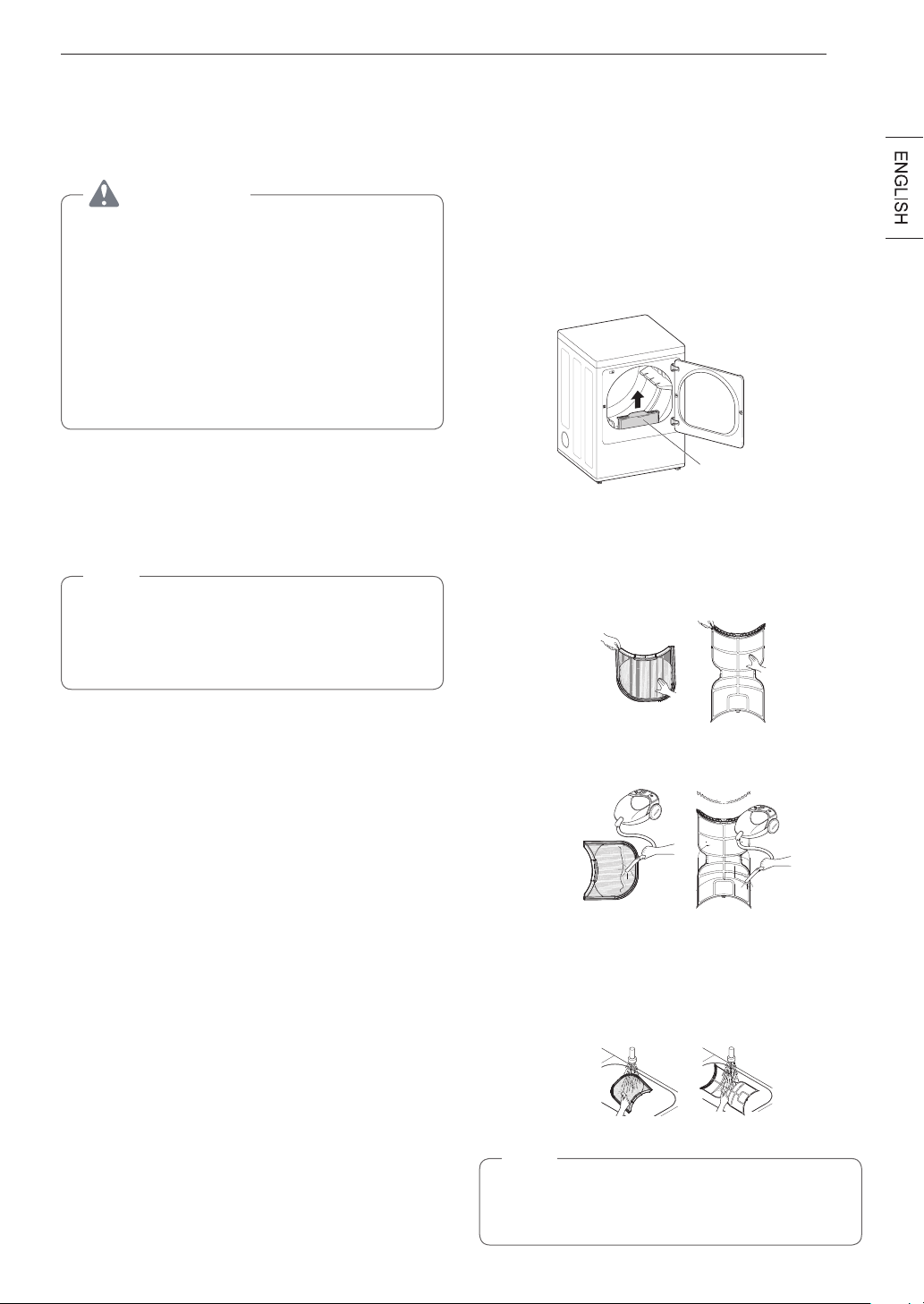
49
MAINTENANCE
MAINTENANCE
Regular Cleaning
WARNING
To reduce the risk of fire, electric shock, or injury
to persons when using this appliance, follow basic
precautions, including the following:
•
Unplugthedryerbeforecleaningtoavoid
the risk of electric shock. Failure to follow
this warning may cause serious injury, fire,
electrical shock, or death.
•
Neveruseharshchemicals,abrasive
cleaners,orsolventstocleanthewasher.
They will damage the finish.
Cleaning the Exterior
Proper care of your dryer can extend its life. The
outside of the machine can be cleaned with warm
water and a mild, nonabrasive household detergent.
Immediately wipe off any spills with a soft, damp cloth.
NOTE
•
Do not use methylated spirits, solvents, or
similar products.
•
Never use steel wool or abrasive cleansers;
they can damage the surface.
Cleaning the Interior
Wipe around the door opening and seal with a soft,
damp cloth to prevent lint and dust buildup that could
damage the door seal.
Clean the window with a soft cloth dampened with
warm water and a mild, nonabrasive household
detergent, then wipe dry.
The stainless steel drum can be cleaned with a
conventional stainless steel cleaner, used according
to the manufacturer’s specifications. Never use steel
wool or abrasive cleansers; they may scratch or
damage the surface.
Cleaning Around and Under the Dryer
Vacuum lint and dust from around the dryer and
underneath it regularly. Vent ductwork should be
checked for lint buildup and cleaned at least once per
year. If any noticeable reduction in airflow or drying
performance occurs, immediately check ductwork for
obstructions and blockages.
Maintaining Ductwork
Vent ductwork should be checked for lint buildup once
per month and cleaned at least once per year. If any
noticeable reduction in airflow or drying performance
occurs, immediately check ductwork for obstructions
and blockages. Contact a qualified technician or
service provider.
Cleaning the Lint Filter
Always clean the lint from the filter after every cycle.
Lint Filter
To clean, open the dryer door and pull the lint filter
straight up. Then:
1
For everyday cleaning, roll any lint off the filter
with your fingers, or
2
Vacuum the lint filter.
3
If the lint filter has become very dirty or clogged
with fabric softener, wash the lint filter in warm,
soapy water and allow it to dry thoroughly before
reinstalling.
NOTE
NEVER operate the dryer without the lint filter in
place. NEVER operate the dryer with a wet lint
filter.
50
TROUBLESHOOTING
TROUBLESHOOTING
FAQs:FrequentlyAskedQuestions
Q: When I press a button, why does my dryer beep and then nothing happens?
A: The Control Lock feature is turned on. To turn off Control Lock, turn the dryer on, then press and hold
the button that has *Control Lock on or under it for 3 seconds.
Q: Why does my dryer take so long to dry clothes?
A: Proper airflow is critical to the efficient operation of clothes dryers. A lint filter which is full of lint or
clogged with fabric softener sheet residue can reduce the airflow to the point that the time required
to dry clothing will be greatly increased. Another factor affecting dry time is your home exhaust
system. An exhaust system which is dirty and clogged with lint, or is excessively long, needs to be
professionally cleaned or repaired.
Q: Whydoesmydryerstartbyitselfeveryfewminutes?
A: This is how the Wrinkle Care feature works. The dryer runs briefly every few minutes for up to 3 hours
after the cycle finishes. This feature is designed to help prevent wrinkles from setting in when the
dryer is not unloaded immediately after the cycle is finished.
Q: Why does my dryer show 3 minutes when I select the Steam Fresh
TM
cycle?
A: When the Steam Fresh
TM
cycle is selected, the dryer displays the number of garments rather than the
estimated cycle time, until the cycle is started. Use the More Time or Less Time buttons to adjust the
load size setting for the number of garments you desire. For a large load or single bulky item use the
(big) setting.
User Support Videos
For further assistance, there are videos and tutorials
available through the LG.com website.
1
On the lg.com/us home page, hover over the
Support menu tab to bring up the menu selections.
Select
Videos & Tutorials
.
2
Type
Dryer
in the search box on the new page and
click the Search button.
Scan this QR code to quickly access the
video search page on the LG website.
Once there, type
Dryer
in the search box.
51
TROUBLESHOOTING
BeforeCallingforService
This dryer is equipped with an automatic error-monitoring system to detect and diagnose problems at an early
stage. If the dryer does not function properly or does not function at all, check the following before you call for
service.
Operation
Problem Possible Cause Solutions
The Flow Sense
TM
indicator remains
activeafterclearing
the restriction in the
venting.
After clearing the restriction, the
Flow Sense
TM
systemrequires
multiple,consecutivecyclesto
determine that the performance
valuehasimprovedbeforethe
Flow Sense
TM
indicator is reset.
If the Flow Sense
TM
indicator remains
active for more than five cycles after
the restriction has been cleared, call for
service.
Dryer will not turn on
Power cord is not properly
plugged in.
Make sure that the plug is securely
plugged into a grounded outlet matching
the dryer’s rating plate.
House fuse is blown, circuit
breaker has tripped, or power
outage has occurred.
Reset circuit breaker or replace fuse. Do
not increase fuse capacity. If the problem
is a circuit overload, have it corrected by
a qualified electrician.
Dryer does not heat
House fuse is blown, circuit
breaker has tripped, or power
outage has occurred.
Reset circuit breaker or replace fuse. Do
not increase fuse capacity. If the problem
is a circuit overload, have it corrected by
a qualified electrician.
NOTE
Due to the design of electric dryers,
it is possible for a circuit problem to
allow an electric dryer to run without
heat.
Gassupplyorserviceisturned
off (gas models only).
Confirm that the house gas shutoff and
the dryer gas shutoff valves are both fully
open. Even if gas is not supplied to the
dryer, it will run and display error code.
Verify that other gas appliances in the
home are working normally.
EnergySaveroptionselected
(on some models)
If using the Cotton/Normal cycle, deselect
the energy saver option. The Energy
Saver option is selected by default. This
option reduces energy use by adding
an air dry section to the beginning of the
cycle. It is normal to feel no heat at the
beginning of the cycle while in Energy
Saver mode.
Display show error
code nP
Electric dryer power cord is not
connected correctly, or house
power supply is incorrect.
Check the power supply or the connection
of the power cord to the terminal block.
Display show error
code gAS
Gassupplyorserviceturned
off(Gas models only).
Confirm that house gas shutoff and the
dryer gas shutoff are both fully open.
52
TROUBLESHOOTING
Problem Possible Cause Solutions
Clothes take too long to
dry
Exhaust ducts are blocked, dirty,
or duct run is too long.
Confirm that the exhaust duct is properly
configured and free of debris, lint, and
obstructions. Make sure that outside wall
dampers can open properly and are not
blocked, jammed, or damaged.
Load is not properly sorted.
Separate heavy items from lightweight
items. Larger and heavier items take
longer to dry. Light items in a load with
heavy items can fool the sensor because
the light items dry faster.
Clothes take too long to
dry
Largeloadofheavyfabrics.
Heavy fabrics take longer to dry because
they tend to retain more moisture. To help
reduce and maintain more consistent
drying times for large and heavy fabrics,
separate these items into smaller loads of
a consistent size.
Dryer controls are not set
properly.
Use the appropriate control settings for
the type of load you are drying. Some
loads may require an adjustment of the
dry level setting for proper drying.
Lint filter needs to be cleaned.
Remove the lint from the filter before
every load. With the lint removed, hold
the filter up to a light to see if it is dirty or
clogged. With some loads that produce
high amounts of lint, such as new bath
towels, it may be necessary to pause the
cycle and clean the filter during the cycle.
House fuse is blown, circuit
breaker has tripped, or power
outage has occurred.
Reset circuit breaker or replace fuse. Do
not increase fuse capacity. If the problem
is a circuit overload, have it corrected by
a qualified electrician.
NOTE
Due to the design of electric dryers,
it is possible for a circuit problem to
allow an electric dryer to run without
heat.
Dryerisoverloaded.
Divide extra large loads into smaller
loads for better drying performance and
efficiency.
Dryer is underloaded.
If you are drying a very small load, add a
few extra items to ensure proper tumbling
action. If the load is very small and you
are using SENSOR DRY cycles, the
electronic control cannot properly sense
the dryness of the load and may shut off
too soon. Use TIME DRY or add some
extra wet clothes to the load.

53
TROUBLESHOOTING
Problem Possible Cause Solutions
Clothes take too long to
dry
EnergySaveroptionselected
(on some models)
If using the Cotton/Normal cycle, deselect
the Energy Saver option. This option
reduces energy use by adding an air dry
section to the beginning of the cycle.
Drying time is not
consistent
Heat settings, load size, or
dampness of clothing is not
consistent.
The drying time for a load will vary
depending on the type of heat used
(electric, natural gas, or LP gas), the
size of the load, the type of fabrics, the
wetness of the clothes, and the condition
of the exhaust duct and lint filter. Even an
unbalanced load in the washer can cause
poor spinning, resulting in wetter clothes
which will take longer to dry.
54
TROUBLESHOOTING
Performance
Problem Possible Cause Solutions
Greasy or dirty spots
on clothes
Fabric softener used incorrectly.
Confirm and follow the instructions
provided with your fabric softener.
Clean and dirty clothes are being
dried together.
Use your dryer to dry only clean items.
Soil from dirty clothes can transfer to the
clean clothes in the same or later loads.
Clothes were not properly
cleaned or rinsed before being
placed in the dryer.
Stains on dried clothes could be stains
that were not removed during the washing
process. Make sure that clothes are being
completely cleaned or rinsed according
to the instructions for your washer and
detergent. Some difficult soils may require
pre-treating prior to washing.
Clothes are wrinkled
Clothesdriedtoolong(over
dried).
Over drying a load of laundry can lead to
wrinkled clothes. Try a shorter drying time
or LESS DRY setting and remove items
while they still retain a slight amount of
moisture.
Clothes left in dryer too long after
cycle ends.
Use the WRINKLE CARE option. This
feature will tumble the clothes briefly
every few minutes for up to 3 hours to
help prevent wrinkling.
Clothes are shrinking
Garment care instructions are not
being followed.
To avoid shrinking your clothes, always
consult and follow fabric care instructions.
Some fabrics will naturally shrink when
washed. Other fabrics can be washed but
will shrink when dried in a dryer. Use a
low or no heat setting.
Lint on clothes
Lint filter not cleaned properly.
Remove the lint from the filter before
every load. With the lint removed, hold
the filter up to a light to see if it is dirty
or clogged. If it looks dirty, follow the
cleaning instructions. With some loads
that produce high amounts of lint, it may
be necessary to clean the filter during the
cycle.
Laundry not sorted properly.
Some fabrics are lint producers (i.e., a
fuzzy white cotton towel) and should be
dried separately from clothes that are lint
trappers (i.e., a pair of black linen pants).
55
TROUBLESHOOTING
Problem Possible Cause Solutions
Lint on clothes
Excess static in clothes.
Use a fabric softener to reduce static
electricity. Be sure to follow the
manufacturer’s instructions. Overdrying
a load of laundry can cause a buildup of
static electricity. Adjust settings and use a
shorter drying time, or use SENSOR DRY
cycles.
Dryerisoverloaded.
Divide extra large loads into smaller loads
for drying.
Tissue, paper, etc., left in pockets.
Check pockets thoroughly before washing
and drying clothes.
Excess static in clothes
after drying
Fabric softener is not used or
used incorrectly.
Use a fabric softener or the STATIC
SHIELD option, if equipped, to reduce
static electricity. Be sure to follow the
manufacturer’s instructions.
Clothes dried too long
(overdried).
Overdrying a load of laundry can cause
a buildup of static electricity. Adjust
settings and use a shorter drying time, or
use AUTO DRY cycles. Select a LESS
DRY setting on SENSOR DRY cycles, if
necessary.
Drying synthetics, permanent
press, or synthetic blends.
These fabrics are naturally more prone to
static buildup. Try using fabric softener, or
use LESS DRY and/or shorter TIME DRY
time settings.
Clotheshavedamp
spots after a SENSOR
DRY cycle.
Verylargeloadorverysmallload.
Single large item such as a
blanket or comforter.
If items are too tightly packed or too
sparse the sensor may have trouble
reading the dryness level of the load. Use
a Time Dry cycle for very small loads.
Large, bulky items such as blankets
or comforters can sometimes wrap
themselves into a tight ball of fabric. The
outside layers will dry and register on the
sensors, while the inner core remains
damp. When drying a single bulky item, it
may help to pause the cycle once or twice
and rearrange the item to unwrap and
expose any damp areas.
To dry a few remaining damp items from
a very large load or a few damp spots
on a large item after a sensor cycle has
completed, empty the lint trap, then set a
Time Dry cycle to finish drying the item(s).
56
TROUBLESHOOTING
Steam Functions (Steam Models)
Problem Possible Cause Solutions
Water drips from nozzle
when STEAM CYCLE
starts
This is normal.
This is steam condensation. The dripping
water will stop after a short time.
Garments still wrinkled
after Steam Fresh
TM
Toomanyoroverlydifferent
types of garments in dryer.
Small loads of 1 to 5 items work best.
Load fewer garments. Load similar types
of garments.
Creases or pleats are
gone from garments
after Steam Fresh
TM
The function of this cycle is to
removewrinklesfromfabric.
Use an iron to replace creases and pleats
in garments.
Garmentshavestatic
after using the Reduce
Static option
This is normal.
The amount of static experienced will
depend on the individual moisture level in
the skin.
Garments are too damp
or too dry after using
the Reduce Static
option
Correct drying options not
selected.
Select the load weight manually before
starting the Reduce Static option.
Garments are not
uniformly damp after
using the Easy Iron
option
Number of garments or load
size not properly selected at the
beginning of the cycle.
Select the correct number of garments or
load size before starting the cycle.
Steam does not
generate, but no error
code is shown
Waterlevelerror.
Unplug dryer and call for service.
Water drips from door
during STEAM CYCLE
This is normal.
Condensation will normally form on the
inside of the dryer door during steam
operation. Some condensation may drip
out the bottom of the door.
Steamisnotvisible
during STEAM CYCLE
This is normal.
Steam vapor is difficult to see when the
door is closed. However, condensation
will normally form on the inside of
the dryer door if the steam system is
operating normally.
Drum does not turn
during STEAM CYCLE
This is normal.
The drum is turned off so that the steam
vapor remains in the drum. The drum will
normally turn for about 2 seconds once a
minute.
Cannot see steam
vaporatthebeginning
of cycle
This is normal.
Steam is released at different stages of
the cycle for each option.
Odors remain in
clothing after Steam
Fresh
TM
Steam Fresh
TM
didnotremove
odor completely.
Fabrics containing strong odors should be
washed in a normal cycle.
57
TROUBLESHOOTING
Error Codes
Problem Possible Cause Solutions
Error code: tE1 through
tE7
Temperature sensor failure.
Turn off the dryer and call for service.
Display shows error
code: PS (electric
dryers only)
Power cord is connected
incorrectly.
Check the connection of the power cord
to the terminal block.
*Flow Sense
TM
indicator
shows four bars during
the drying cycle or the
display shows "d80"
after drying
* This warning light
is not a dryer failure
andisnotcoveredby
the dryer warranty.
Contact a duct cleaning
servicetosetupan
appointmenttohave
your exhaust system
cleaned and inspected.
Exhaust system is too long or
has too many turns/restrictions.
Install a shorter or straighter duct run. See
the Installation Instructions for details.
Partial blockage of the ductwork
due to lint buildup or other
foreign object.
Ductwork should be checked/cleaned
immediately. Dryer can be used in this
condition, but drying times will be longer
and energy consumption will increase.
The appliance has detected a
restriction in the external dryer
venting.
If exhaust restrictions are sensed by the
Flow Sense
TM
system, the indicator will
remain on for 2 hours after the end of the
cycle. Opening the door or pressing the
POWER
button will turn off the display.
The Flow Sense
TM
indicator remains
activeafterclearing
the restriction in the
venting.
After clearing the restriction, the
Flow Sense
TM
systemrequires
multiple,consecutivecyclesto
determine that the performance
valuehasimprovedbeforethe
Flow Sense
TM
indicator is reset.
If the Flow Sense
TM
indicator remains
active for more than five cycles after
the restriction has been cleared, call for
service.
indicator light is on
during the drying cycle
Water supply error.
Check steam feeder drawer:
(1) Make sure the steam feeder is filled
with water to the MAX line.
(2) Make sure the steam feeder is seated
properly and the drawer is fully closed.
(3) Turn the dryer off then restart the
STEAM CYCLE.
Do not use distilled water; the water level
sensor in the steam generator will not
work.
Pump not working. Unplug dryer and call
for service.
The display shows
More Time button was pressed.
This display indicates that the steam
option has been set for a “big” item such
as a comforter.
Press the Less Time button to reduce the
indicated load size.
indicator light is on
during the drying cycle
Lint filter not cleaned properly.
Remove the lint from the filter before
every load. With the lint removed, hold
the filter up to a light to see if it is dirty
or clogged. If it looks dirty, follow the
cleaning instructions. With some loads
that produce high amounts of lint, it may
be necessary to clean the filter during the
cycle.
58
TROUBLESHOOTING
Problem Possible Cause Solutions
indicator light is on
during the drying cycle
Water supply error.
Check steam feeder drawer:
(1) Make sure the steam feeder is filled
with water to the MAX line.
(2) Make sure the steam feeder is seated
properly and the drawer is fully closed.
(3) Turn the dryer off then restart the
STEAM CYCLE.
Do not use distilled water; the water level
sensor in the steam generator will not
work.
Pump not working.
Unplug dryer and call for service.
The display shows d80,
d90, d95
The duct work is about 80%-95%
blocked.(“d80”,“d90” or “d95”
error code is displayed for 2
hours only)
House exhaust system blocked.
Do not use the dryer until the exhaust
system has been cleaned and/or repaired.
Using the dryer with a severely restricted
exhaust is dangerous and could result in
a fire or other property damage.
Check the outside dryer vent while the
dryer is operating to make sure there is
strong airflow.
If the exhaust system is extremely long,
have it repaired or rerouted.
Keep the area around the dryer clean and
free of clutter.
Check vent hood for damage or lint
clogging.
Make sure the area around the vent hood
is clear.
59
WARRANTY (USA)
WARRANTY (USA)
ARBITRATION NOTICE: THIS LIMITED WARRANTY CONTAINS AN ARBITRATION PROVISION THAT
REQUIRES YOU AND LG TO RESOLVE DISPUTES BY BINDING ARBITRATION INSTEAD OF IN COURT,
UNLESS YOU CHOOSE TO OPT OUT. IN ARBITRATION, CLASS ACTIONS AND JURY TRIALS ARE NOT
PERMITTED. PLEASE SEE THE SECTION TITLED “PROCEDURE FOR RESOLVING DISPUTES” BELOW.
Should your LG Dryer (“Product”) fail due to a defect in materials or workmanship under normal home use,
during the warranty period set forth below, LG will at its option repair or replace the product. This limited warranty
is valid only to the original retail purchaser of the product and applies only when purchased and used within the
United States including U.S. Territories. Proof of original retail purchase is required to obtain warranty service
under this limited warranty.
Warranty Period Scope of Warranty HOW SERVICE IS HANDLED
One (1) year from date of
original retail purchase
Parts and Labor
LG will provide parts and labor to repair or replace
defective parts.
Three (3) years from date of
original retail purchase
Dryer drum
Parts only. Customer will be responsible for any labor
or in-home service to replace defective parts.
•
Replacement products and parts are warranted for the remaining portion of the original warranty period or
ninety (90) days, whichever is greater.
•
Replacement products and parts may be new or remanufactured.
THIS WARRANTY IS IN LIEU OF ANY OTHER WARRANTY, EXPRESS OR IMPLIED, INCLUDING WITHOUT
LIMITATION, ANY WARRANTY OF MERCHANTABILITY OR FITNESS FOR A PARTICULAR PURPOSE. TO
THE EXTENT ANY IMPLIED WARRANTY IS REQUIRED BY LAW, IT IS LIMITED IN DURATION TO THE
EXPRESS WARRANTY PERIOD ABOVE. NEITHER THE MANUFACTURER NOR ITS U.S. DISTRIBUTOR
SHALL BE LIABLE FOR ANY INCIDENTAL, CONSEQUENTIAL, INDIRECT, SPECIAL, OR PUNITIVE
DAMAGES OF ANY NATURE, INCLUDING WITHOUT LIMITATION, LOST REVENUES OR PROFITS, OR
ANY OTHER DAMAGE WHETHER BASED IN CONTRACT, TORT, OR OTHERWISE.
Some states do not allow the exclusion or limitation of incidental or consequential damages or limitations on how
long an implied warranty lasts, so the above exclusion or limitation may not apply to you. This warranty gives you
specific legal rights and you may also have other rights that vary from state to state.
THIS LIMITED WARRANTY DOES NOT COVER:
•
Service trips to deliver, pick up, or install or repair the product; instruction to the customer on operation of
the product; repair or replacement of fuses or correction of wiring or plumbing, or correction of unauthorized
repairs/installation.
•
Failure of the product to perform during power failures and interruptions or inadequate electrical service.
•
Damage caused by leaky or broken water pipes, frozen water pipes, restricted drain lines, inadequate or
interrupted water supply or inadequate supply of air.
•
Damage resulting from operating the Product in a corrosive atmosphere or contrary to the instructions outlined
in the Product’s owner’s manual.
•
Damage to the Product caused by accidents, pests and vermin, lightning, wind, fire, floods, or acts of God.
•
Damage or failure caused by unauthorized modification or alteration, or if it is used for other than the intended
purpose, or any water leakage where the unit was not properly installed.
•
Damage or failure caused by incorrect electrical current, voltage, or plumbing codes, commercial or industrial
use, or use of accessories, components, or consumable cleaning products that are not approved by LG.
•
Damage caused by transportation and handling, including scratches, dents, chips, and/or other damage to the
finish of your product, unless such damage results from defects in materials or workmanship and is reported
within one (1) week of delivery.
•
Damage or missing items to any display, open box, discounted, or refurbished Product.
•
Products with original serial numbers that have been removed, altered, or cannot be readily determined. Model
and Serial numbers, along with original retail sales receipt, are required for warranty validation.
60
WARRANTY (USA)
•
Increases in utility costs and additional utility expenses.
•
Repairs when your Product is used in other than normal and usual household use (e.g. commercial use, in
offices and recreational facilities) or contrary to the instructions outlined in the Product’s owner’s manual.
•
Costs associated with removal of your Product from your home for repairs.
•
The removal and reinstallation of the Product if it is installed in an inaccessible location or is not installed in
accordance with published installation instructions, including LG’s owner’s and installation manuals.
•
Damage resulting from misuse, abuse, improper installation, repair, or maintenance. Improper repair includes
use of parts not approved or specified by LG.
•
Conversion of product from natural gas or L.P. gas.
Filter is clogged.
•
Not heating, long dry
time
•
Clean the lint filter.
Duct is clogged.
•
Not heating, long dry
time
•
Clean the hood and
duct.
Excessiveduct
length and/or multiple
elbows
•
Not heating, long dry
time
•
Keep exhaust ducts
as short as possible,
using as few elbows
and bends as
possible.
Improperly connected
power cord or
electrical outlet issue.
•
No Power
•
Not Heating
•
Reconnect power
cord, replace house
fuse or reset breaker.
If outlet is issue,
electrician may be
required.
Gasvalveisnot
turned on. (Gas Dryer)
•
Not heating
•
Open the gas valve
DoorReversal
•
Instructions for door
reversal can be
found in the owner’s
manual.
The cost of repair or replacement under these excluded circumstances shall be borne by the consumer.
TO OBTAIN WARRANTY SERVICE AND ADDITIONAL INFORMATION
For additional product information, visit the LG website at http://www.lg.com
For assistance using this product or to schedule service, contact LG Electronics at 1-800-243-0000.
For further assistance, write: LG Electronics, 201 James Record Road, Huntsville, Alabama 35813

61
WARRANTY (USA)
PROCEDURE FOR RESOLVING DISPUTES:
ALL DISPUTES BETWEEN YOU AND LG ARISING OUT OF OR RELATING IN ANY WAY TO THIS LIMITED
WARRANTY OR THE PRODUCT SHALL BE RESOLVED EXCLUSIVELY THROUGH BINDING ARBITRATION,
AND NOT IN A COURT OF GENERAL JURISDICTION. BINDING ARBITRATION MEANS THAT YOU AND LG
ARE EACH WAIVING THE RIGHT TO A JURY TRIAL AND TO BRING OR PARTICIPATE IN A CLASS ACTION.
Denitions.
For the purposes of this section, references to “LG” mean LG Electronics U.S.A., Inc., its parents, subsidiaries
and afliates, and each of their ofcers, directors, employees, agents, beneciaries, predecessors in interest, successors,
assigns and suppliers; references to “dispute” or “claim” shall include any dispute, claim or controversy of any kind whatsoever
(whether based in contract, tort, statute, regulation, ordinance, fraud, misrepresentation or any other legal or equitable theory)
arising out of or relating in any way to the sale, condition or performance of the product or this Limited Warranty.
Notice of Dispute.
In the event you intend to commence an arbitration proceeding, you must rst notify LG in writing at least
30 days in advance of initiating the arbitration by sending a letter to LG at LG Electronics, USA, Inc. Attn: Legal Department-
Arbitration 111 Sylvan Ave, Englewood Cliffs, NJ 07632. You and LG agree to engage in good faith discussions in an attempt
to amicably resolve your claim. The notice must provide your name, address, and telephone number; identify the product that
is the subject of the claim; and describe the nature of the claim and the relief being sought. If you and LG are unable to resolve
the dispute within 30 days, either party may proceed to le a claim for arbitration.
AgreementtoBindingArbitrationandClassActionWaiver.
Upon failure to resolve the dispute during the 30 day period
after sending written notice to LG, you and LG agree to resolve any claims between us only by binding arbitration on an
individual basis, unless you opt out as provided below. Any dispute between you and LG shall not be combined or consolidated
with a dispute involving any other person’s or entity’s product or claim. More specically, without limitation of the foregoing, any
dispute between you and LG shall not under any circumstances proceed as part of a class or representative action. Instead
of arbitration, either party may bring an individual action in small claims court, but that small claims court action may not be
brought on a class or representative basis.
Arbitration Rules and Procedures.
To begin arbitration of a claim, either you or LG must make a written demand for
arbitration. The arbitration will be administered by the American Arbitration Association (“AAA”) and will be conducted before
a single arbitrator under the AAA’s Consumer Arbitration Rules that are in effect at the time the arbitration is initiated (referred
to as the “AAA Rules”) and under the procedures set forth in this section. The AAA Rules are available online at www.adr.org/
consumer. Send a copy of your written demand for arbitration, as well as a copy of this provision, to the AAA in the manner
described in the AAA Rules. You must also send a copy of your written demand to LG at LG Electronics, USA, Inc. Attn: Legal
Department- Arbitration 111 Sylvan Avenue Englewood Cliffs, NJ 07632. If there is a conict between the AAA Rules and the
rules set forth in this section, the rules set forth in this section will govern. This arbitration provision is governed by the Federal
Arbitration Act. Judgment may be entered on the arbitrator’s award in any court of competent jurisdiction. All issues are for the
arbitrator to decide, except that issues relating to the scope and enforceability of the arbitration provision and to the arbitrability
of the dispute are for the court to decide. The arbitrator is bound by the terms of this provision.
GoverningLaw.
The law of the state of your residence shall govern this Limited Warranty and any disputes between us
except to the extent that such law is preempted by or inconsistent with applicable federal law.
Fees/Costs.
You do not need to pay any fee to begin an arbitration. Upon receipt of your written demand for arbitration,
LG will promptly pay all arbitration ling fees to the AAA unless you seek more than $25,000 in damages, in which case the
payment of these fees will be governed by the AAA Rules. Except as otherwise provided for herein, LG will pay all AAA ling,
administration and arbitrator fees for any arbitration initiated in accordance with the AAA Rules and this arbitration provision.
If you prevail in the arbitration, LG will pay your attorneys’ fees and expenses as long as they are reasonable, by considering
factors including, but not limited to, the purchase amount and claim amount. Notwithstanding the foregoing, if applicable law
allows for an award of reasonable attorneys’ fees and expenses, an arbitrator can award them to the same extent that a court
would. If the arbitrator nds either the substance of your claim or the relief sought in the demand is frivolous or brought for an
improper purpose (as measured by the standards set forth in Federal Rule of Civil Procedure 11(b)), then the payment of all
arbitration fees will be governed by the AAA Rules. In such a situation, you agree to reimburse LG for all monies previously
disbursed by it that are otherwise your obligation to pay under the AAA Rules. Except as otherwise provided for, LG waives
any rights it may have to seek attorneys’ fees and expenses from you if LG prevails in the arbitration.
Hearings and Location.
If your claim is for $25,000 or less, you may choose to have the arbitration conducted solely on
the basis of (1) documents submitted to the arbitrator, (2) through a telephonic hearing, or (3) by an in-person hearing as
established by the AAA Rules. If your claim exceeds $25,000, the right to a hearing will be determined by the AAA Rules. Any
in-person arbitration hearings will be held at a location within the federal judicial district in which you reside unless we both
agree to another location or we agree to a telephonic arbitration.
Opt Out.
You may opt out of this dispute resolution procedure. If you opt out, neither you nor LG can require the other to
participate in an arbitration proceeding. To opt out, you must send notice to LG no later than 30 calendar days from the date
of the rst consumer purchaser’s purchase of the product by either: (i) sending an e-mail to [email protected], with the subject
line: “Arbitration Opt Out” or (ii) calling 1-800-980-2973. You must include in the opt out e-mail or provide by telephone: (a)
your name and address; (b) the date on which the product was purchased; (c) the product model name or model number; and (d)
the serial number (the serial number can be found (i) on the product; or (ii) online by accessing https://www.lg.com/us/support/
repair-service/schedule-repair-continued and clicking on “Find My Model & Serial Number”).
You may only opt out of the dispute resolution procedure in the manner described above (that is, by e-mail or telephone);
no other form of notice will be effective to opt out of this dispute resolution procedure. Opting out of this dispute resolution
procedure will not affect the coverage of the Limited Warranty in any way, and you will continue to enjoy the full benets of
the Limited Warranty. If you keep this product and do not opt out, then you accept all terms and conditions of the arbitration
provision described above.

Memo

Memo

Memo

SECADORA
MANUAL DEL PROPIETARIO
Lea detenidamente el manual del propietario antes de poner el electrodoméstico en
funcionamiento y consérvelo a mano en todo momento para su referencia.
DLEX7900*E DLGX7901*E
DLEX7800*E DLGX7801*E
DLEX7880*E DLGX7881*E
www.lg.com
Copyright © 2019-2020 LG Electronics Inc. Todos los Derechos Reservados.
ESPAÑOL

2 ÍNDICE
ÍNDICE
3
INSTRUCCIONES DE SEGURIDAD
4 INSTRUCCIONES IMPORTANTES DE
SEGURIDAD
7 INSTRUCCIONES DE CONEXIÓN A TIERRA
8
CARACTERÍSTICAS DEL
PRODUCTO
9
DESCRIPCIÓN GENERAL DEL
PRODUCTO
9 Partes
9 Accesorios
9 Kit de fijación de seguridad
9 Puerta reversible de doble sentido
(en algunos modelos)
10
INSTALACIÓN
10 Descripción general de la instalación
10 Especificaciones del producto
11 Requisitos del lugar de instalación
11 Espacios libres
13 Nivelación de la secadora
13 Inversión de la puerta
21 Instalación del kit de ventilación lateral
22 Ventilación de la secadora
25 Conexión de secadoras de gas
27 Conexión de secadoras eléctricas
31 Revisión final de la instalación
32 Prueba de instalación (Revisión de conductos)
34
FUNCIONAMIENTO
34 Cómo usar la secadora
35 Revise el filtro de pelusa antes de cada carga
35 Clasificación de cargas
35 Carga de la secadora
36 Uso de la función LG EasyLoad
TM
37 Panel de control
39 Guía de ciclos
41 Ajustes y opciones de ciclo
43 Funciones de vapor (modelos de vapor)
44 Guía de ciclo de vapor
45
FUNCIONES INTELIGENTES
45 Aplicación LG ThinQ
48 Función Smart Diagnosis™ (Diagnóstico
Inteligente)
49
MANTENIMIENTO
49 Limpieza regular
50
SOLUCIÓN DE PROBLEMAS
50 Preguntas frecuentes
51 Antes de llamar al servicio técnico
59
GARANTÍA (EE. UU.)
3INSTRUCCIONES DE SEGURIDAD
INSTRUCCIONES IMPORTANTES DE SEGURIDAD
LEA TODAS LA INSTRUCCIONES ANTES DE USAR
Medidas de seguridad para una Secadora
ADVERTENCIA
ADVERTENCIA:
Peligro de incendio
No seguir exactamente las advertencias de seguridad podría provocar
lesiones graves, la muerte o daños a la propiedad.
No instale un ventilador auxiliar en el conducto de extracción.
Instale todas las secadoras de ropa de conformidad con las instrucciones
de instalación del fabricante de la secadora.
PELIGRO DE INCENDIO O EXPLOSIÓN
No seguir exactamente las advertencias de seguridad podría provocar
lesiones graves, la muerte o daños a la propiedad.
• Noalmaceneniusegasolinauotroslíquidosovaporesinflamablescerca
de este artefacto ni de ningún otro.
• QUÉHACERSIHUELEGAS
- No intente encender ningún aparato.
-Notoqueningúninterruptoreléctriconiuseningúnteléfonodesu
edificio.
- Evacue a todos los ocupantes de la habitación, el edificio o el área.
- Llame a su compañía de gas inmediatamente desde el teléfono de un
vecino. Siga las instrucciones de la compañía de gas.
- Si no puede comunicarse con su compañía de gas, llame al
departamento de bomberos.
• Installationandservicemustbeperformedbyaqualifiedinstaller,service
agency or your gas supplier.
4 INSTRUCCIONES DE SEGURIDAD
ADVERTENCIA - RIESGO DE INCENDIO
Instale la secadora de ropa de acuerdo con las instrucciones del fabricante
y los códigos locales.
•Lainstalacióndelasecadoraderopadebeserrealizadaporuntécnico
calificado.
• Noinstalelasecadoraderopaconmaterialesdeventilacióndeplástico
flexibles. Si se instala un conducto flexible metálico (tipo lámina de
aluminio), este debe ser de un tipo específico avalado por el fabricante
comoaptoparaelusoconsecadorasderopa.Essabidoquelos
materiales de ventilación flexibles se colapsan, se aplastan con facilidad
y atrapan pelusas. Estas condiciones obstruirán el flujo de aire de la
secadora y aumentarán el riesgo de incendio.
•Parareducirelriesgodelesionesgravesomuerte,sigatodaslas
instrucciones de instalación.
Su seguridad y la seguridad de los demás son muy importantes.
Hemos proporcionado muchos mensajes de seguridad importantes en este manual y en su aparato. Siempre lea y obedezca
todos los mensajes de seguridad.
Este es el símbolo de alerta de seguridad.
Este símbolo lo alerta sobre peligros potenciales que pueden ocasionar la muerte o una lesión a usted y a los demás.
Todos los mensajes de seguridad estarán seguidos del símbolo de alerta de seguridad y de la palabra PELIGRO,
ADVERTENCIA o PRECAUCIÓN.
Estos términos significan lo siguiente:
PELIGRO
:
Usted morirá o sufrirá lesiones graves si
no
sigue las instrucciones inmediatamente.
ADVERTENCIA
:
Podría sufrir lesiones graves o la muerte si no sigue las instrucciones.
PRECAUCIÓN
:
Usted puede sufrir lesiones leves o causar daños en el producto si no sigue las
instrucciones.
Todos los mensajes de seguridad le brindarán información sobre los posibles riesgos, sobre cómo reducir la posibilidad de
sufrir lesiones y le dirán qué puede suceder si las instrucciones no se cumplen.

5INSTRUCCIONES DE SEGURIDAD
INSTRUCCIONES IMPORTANTES DE SEGURIDAD
ADVERTENCIA
Parareducirelriesgodeincendio,descargaseléctricasolesionespersonalesalusarsuequipo,sigalasprecauciones
básicas, incluso lo siguiente:
Instalación
•
Mantenga el área alrededor de la abertura de escape y las
áreas adyacentes libres de acumulación de pelusa, polvo y
tierra.
•
No instale ni almacene esta secadora en lugares donde
pueda estar expuesta a la intemperie.
•
Nocoloqueprendasexpuestasaaceitesdecocinaen
su secadora.
Las prendas contaminadas con aceites de
cocina pueden contribuir a producir una reacción química
que puede ocasionar que una carga se incendie.
•
Conecte la secadora a tierra apropiadamente según los
códigosylasordenanzasvigentes.
Siga las instrucciones
de instalación. Si la secadora no se encuentra conectada
a tierra adecuadamente, se pueden producir descargas
eléctricas.
•
Antes de usarse, la secadora debe estar correctamente
instalada como se describe en este manual.
Si
la secadora no se encuentra conectada a tierra
adecuadamente, se pueden producir descargas eléctricas.
•
Instale y almacene la secadora en un lugar que no esté
expuesto a temperaturas inferiores al punto de congelación
ni a la intemperie.
•
Todas las reparaciones y servicios deberán ser
realizadosporpersonaldeservicioautorizado,amenos
quesedenotrasrecomendacionesespecíficaseneste
Manualdelpropietario.Utilicesolopiezasdefábrica
autorizadas.
Si no se cumple con esta advertencia, se
podrán producir lesiones graves, incendios, descargas
eléctricas o la muerte.
•
Con el fin de reducir el riesgo de descargas eléctricas,
no instale la secadora en espacios húmedos.
Si no se
cumple con esta advertencia, se podrán producir lesiones
graves, incendios, descargas eléctricas o la muerte.
•
Conecte a un circuito eléctrico de la capacidad correcta,
protegido y del tamaño adecuado para evitar la
sobrecarga eléctrica.
Un circuito eléctrico inadecuado se
puede fundir, lo que creará riesgo de descargas eléctricas y/
o de incendio.
•
Quitetodosloselementosdeembalajeydeseche
adecuadamente todos los materiales de envío.
Si esto
no se cumple, se podrán producir quemaduras, un incendio,
una explosión o la muerte.
•
Paraunainstalaciónenelgaraje,coloquelasecadoraa
un altura mínima de 18 pulgadas (45,7 cm) sobre el piso.
Si esto no se cumple, se podrán producir quemaduras, un
incendio, una explosión o la muerte.
•
Mantenga todos los envoltorios alejados de los niños.
Los materiales de embalaje pueden resultar peligrosos para
los niños. Existe riesgo de asfixia.
•
Noinstalelasecadoracercadeunelementoquegenere
calor, como una estufa, un horno o un calentador.
Si
no se cumple con esta advertencia, se pueden producir
deformación, humo o un incendio en el equipo.
•
No coloque velas, cigarros ni otros objetos inflamables sobre
el producto. Se podrá producir un derrame de cera, humo o
un incendio.
•
Quitetodalapelículavinílicaqueprotegealproducto.
Si
no lo hace puede ocasionar daños en el equipo, humo o un
incendio.
•
Las secadoras de gas DEBEN tener escape al exterior.
El incumplimiento de estas instrucciones podrá producir un
incendio o la muerte.
•
El sistema de escape de la secadora debe tener salida al
exterior de la vivienda. Si la secadora no tiene salida al
exterior, se expulsará pelusa fina y grandes cantidades de
humedad al área de lavado. Una acumulación de pelusa en
cualquier parte de la casa puede crear riesgos para la salud
y riesgo de incendio.
•
Use únicamente conductos de metal semirrígidos o flexibles
de 4 pulgadas (10,2 cm) de diámetro dentro del gabinete de
la secadora o para escape al exterior. El uso de conductos
de plástico o de otro material combustible puede causar
incendios. Los conductos agujereados pueden causar
incendios si se colapsan o se restringen de alguna manera
durante el uso o la instalación.
•
No se suministran los conductos con la secadora;
deberá obtenerlos en su localidad. La tapa terminal
deberá tener reguladores de tiro con bisagras para
prevenir una contracorriente de aire cuando no se use
la secadora.
El incumplimiento de estas instrucciones podrá
producir un incendio o la muerte.
•
El conducto de escape deberá tener 4 pulgadas (10,2 cm)
de diámetro sin obstrucciones. El conducto de escape
deberá mantenerse lo más corto posible. Asegúrese
de limpiar los conductos antiguos antes de instalar su
secadora nueva.
El incumplimiento de estas instrucciones
podrá producir un incendio o la muerte.
•
Se recomienda el uso de conductos rígidos,
semirrígidos o flexibles entre la secadora y la pared.
Todoslosconductosmetálicosdetransiciónqueno
sean rígidos deben estar aprobados por UL. El uso
de otros materiales para el conducto de transición
afectará el tiempo de secado.
El incumplimiento de estas
instrucciones podrá producir un incendio o la muerte.
•
No utilice tornillos para chapa metálica ni ningún
otrotipodesujetadoresqueseextiendandentrodel
conducto y puedan atrapar pelusa, y, así, reducir
la eficiencia del sistema de escape. Asegure todas
las uniones con cinta adhesiva para conductos.
Para obtener más detalles, siga las instrucciones de
instalación.
El incumplimiento de estas instrucciones podrá
producir un incendio o la muerte.
•
Algunas piezas internas no están conectadas a tierra
intencionalmente y pueden presentar un riesgo de descarga
eléctrica solamente durante la operación.
Personal de servicio – No permita que entren en contacto
las siguientes piezas mientras el artefacto se encuentre
energizado: Tablero de control

6 INSTRUCCIONES DE SEGURIDAD
GUARDE ESTAS INSTRUCCIONES
Funcionamiento
•
Lea todas las instrucciones antes de usar el aparato.
•
No seque prendas que hayan sido limpiadas, lavadas,
remojadas o salpicadas previamente con gasolina, solventes
de limpieza en seco u otras sustancias inflamables o
explosivas, ya que emanan vapores que podrían inflamarse
o explotar.
•
No introduzca las manos en la secadora cuando el tambor
esté en movimiento.
•
No deje que los niños jueguen sobre la secadora ni dentro
de ella. Cuando se usa la secadora cerca de los niños, se
necesita una supervisión estricta.
•
No use suavizantes para telas ni productos para eliminar
estática a menos que hayan sido recomendados por el
fabricante del suavizante o del producto.
•
No use calor para secar prendas que contengan espuma de
caucho o materiales de textura similares al caucho.
•
No manipule indebidamente los controles.
•
Siempre revise el interior de la secadora para verificar
que no haya objetos extraños. El incumplimiento de estas
instrucciones podrá producir un incendio o la muerte.
•
No guarde plásticos, papel o ropa que puedan quemarse
o derretirse sobre la secadora en funcionamiento. El
incumplimiento de estas instrucciones podrá producir un
incendio o la muerte.
•
Tenga cuidado al abrir y cerrar la puerta. Los dedos y las
manos podrian quedar enganchados en la puerta y causar
danos si esta cae hacia delante de forma inadvertida.
•
Nocoloqueobjetospesadosniseapoyesobrelaparte
superior de la puerta abierta.
•
N
o intente abrir la puerta de tipo cesto más de 40
grados.
•
La secadora podría volcarse hacia delante y causarle
lesiones personales o danos materiales.
•
No coloque objetos pesados de la secadora.
•
Los aparatos de gas pueden causar una exposición leve a
cuatro sustancias potencialmente dañinas, principalmente
benceno, monóxido de carbono, formaldehído y hollín,
generado principalmente por la combustión parcial del gas
natural o combustibles licuados del petróleo.
•
Las secadoras correctamente calibradas minimizarán
la combustión incompleta. Para minimizar aún más la
exposición a estas sustancias, se puede dotar a la secadora
de la ventilación adecuada al exterior.
•
No coloque objetos que han sido expuestos a aceites de
cocina en la secadora. Los objetos contaminados con
aceites de cocina pueden contribuir a una reacción química
que podría ocasionar un incendio.
Para reducir el riesgo de incendios ocasionados por una
tanda de ropa contaminada, la parte final del ciclo de secado
se lleva a cabo sin calor (período de enfriamiento). Evite
detener la secadora antes de que el ciclo de secado finalice,
a menos que retire todas las prendas rápidamente y las
separe para disipar el calor.
•
No deje que los niños o las mascotas se suban dentro del
tambor de su secadora.
•
No meta animales vivos como mascotas dentro del aparato.
•
No coloque ninguna parte de su cuerpo, ya sean manos o
pies, ni objetos de metal debajo del aparato.
•
No deje que sus manos se atoren al abrir o cerrar la puerta
de su secadora.
Vapor (solo para modelos con función de vapor):
•
No abra la secadora durante el ciclo de vapor.
Si no
se siguen estas instrucciones, se podría producir una
quemadura.
•
Nosequeprendasquehayansidolimpiadas,lavadas,
remojadas o salpicadas previamente con gasolina,
solventesdelimpiezaensecouotrassustancias
inflamablesoexplosivas,yaqueemananvaporesque
podrían inflamarse o explotar.
El incumplimiento de estas
instrucciones podrá producir un incendio o la muerte.
•
No llene el alimentador de vapor con gasolina, solventes
delimpiezaensecouotrassustanciasinflamableso
explosivas.
El incumplimiento de estas instrucciones podrá
producir un incendio o la muerte.
•
Notoquelaboquilladevapordeltambordurantedel
ciclo de vapor o después de él.
Si no se siguen estas
instrucciones, se podría producir una quemadura.
•
No llene el alimentador de vapor con agua caliente
(superior a 86 °F/30 °C).
Si no se siguen estas
instrucciones, se podría producir una quemadura.
Mantenimiento
•
No repare ni sustituya ninguna pieza de este aparato
ni intente realizar ningún tipo de servicio a menos que
se recomiende específicamente en las instrucciones
de mantenimiento del usuario o en las instrucciones de
reparación del usuario publicadas que usted comprenda y
pueda realizarlas.
•
Limpie el filtro de pelusas antes o después de cada carga.
•
El interior del aparato y el conducto de escape deben ser
limpiados periódicamente por personal de mantenimiento
calificado.
•
Antes de sacar de servicio o desechar la secadora, extraiga
la puerta del compartimiento de secado.
•
Algunas piezas internas no están conectadas a tierra
intencionalmente y pueden presentar un riesgo de descarga
eléctrica solamente durante la operación.
Personal de servicio – No permita que entren en contacto
las siguientes piezas mientras el artefacto se encuentre
energizado: Tablero de control

7INSTRUCCIONES DE SEGURIDAD
INSTRUCCIONES DE CONEXIÓN A TIERRA
ADVERTENCIA
Laconexióninadecuadadelconductorparalaconexiónatierradelequipopuedeproducirunriesgodedescarga
eléctrica. Consulte a un electricista calificado o a personal de mantenimiento si tiene dudas sobre si el aparato se
encuentra conectado a tierra apropiadamente.
•
Este aparato debe estar conectado a tierra.
En caso de
mal funcionamiento o avería, la conexión a tierra reducirá
el riesgo de descarga eléctrica, ya que proporcionará una
trayectoria de menor resistencia para la corriente eléctrica.
•
Esteaparatodebeestarequipadoconuncableque
tengaunconductorparalaconexiónatierradelequipo
y un enchufe con conexión a tierra.
El enchufe deberá
estar conectado a una toma de corriente instalada en forma
adecuada y con conexión a tierra de acuerdo con todos los
códigos y las ordenanzas locales.
•
Nomodifiqueelenchufe.
Si el enchufe no entra en la toma
de corriente, debe solicitar que un electricista calificado
instale una toma de corriente adecuada.
•
Este aparato debe estar conectado a un sistema de
cableado de metal permanente con conexión a tierra
o se debe tender un conductor para la conexión a
tierradelequipoconlosconductoresdelcircuitoy
se debe conectar al terminal o al cable de tierra del
aparato.
Si la secadora no se encuentra conectada a tierra
adecuadamente, se pueden producir descargas eléctricas.
•
La secadora siempre debe estar conectada a su toma de
corrienteindividual,quedebetenerunvoltajenominal
quecoincidaconlaplacadedatosdeservicio.
Esto
brinda el mejor rendimiento y, además, impide la sobrecarga
de los circuitos eléctricos de la casa, lo que podría causar
peligro de incendio debido a los cables sobrecalentados.
•
Nunca desenchufe su secadora tirando del cable de
alimentación. Siempre agarre el enchufe firmemente
y tire de él hacia fuera de la toma de corriente para
retirarlo.
El cable de alimentación se puede dañar, lo que
puede producir riesgo de incendio o de descarga eléctrica.
•
Repare o reemplace de inmediato todos los cables de
alimentación pelados o dañados. No use un cable con
grietas o abrasión visibles en sentido longitudinal o en
sus extremos.
El cable de alimentación se puede derretir, lo
que producirá peligro de descarga eléctrica y/o de incendio.
•
Al instalar o trasladar la secadora, tenga cuidado de
nopellizcar,aplastarnidañarelcabledealimentación.
Esto evitará lesiones o daños en la secadora a causa de
incendios o descargas eléctricas.
•
Enningunacircunstancia,corteoquiteelbornede
conexión a tierra del cable de alimentación.
Para evitar
lesiones personales o daños en la secadora, el cable de
alimentación eléctrica debe estar conectado a una toma de
corriente debidamente conectada a tierra.
•
Por motivos de seguridad personal, esta secadora debe
estar conectada a tierra adecuadamente.
Si esto no se
cumple, se podrán producir descargas eléctricas o lesiones.
•
Consulte las instrucciones de instalación de este manual
paraobtenerlosrequisitoseléctricosespecíficosdesu
modelo.
Si no se cumplen estas instrucciones, se podrá
causar riesgo de descargas eléctricas y/o incendios.
•
Esta secadora debe estar conectada a una toma
de corriente conectada a tierra adecuadamente.
Si la secadora no se encuentra conectada a tierra
adecuadamente, se pueden producir descargas
eléctricas. Contrate a un electricista calificado para
quereviselatomadecorrientedelaparedyel
circuitoeléctricoyseaseguredequelatomaestá
correctamente conectada a tierra.
Si no se cumplen
estas instrucciones, se podrá causar riesgo de descargas
eléctricas y/o incendios.
8 CARACTERÍSTICAS DEL PRODUCTO
CARACTERÍSTICAS DEL PRODUCTO
Panel de control fácil de usar
Una completa selección de funciones de fácil manejo simplifica la operación de la secadora.
Puerta reversible de doble sentido para un fácil acceso
La función LG EasyLoad™ le permite abrir la puerta desde la parte superior, por lo que podrá cargar la secadora de forma
sencilla sin que se le caigan las prendas al suelo. La puerta también se abre por completo para permitir un fácil acceso en la
carga y descarga de prendas más voluminosas. La bisagra de la puerta puede invertirse para ajustarse a la ubicación de la
instalación.
Funciones de vapor (modelos de vapor)
La tecnología de vapor de LG permite inyectar un chorro de vapor en forma de remolino en los tejidos para refrescar la ropa,
reducir la estática y facilitar el planchado. Simplemente, seleccione el ciclo Steam Fresh™ o el ciclo Prevención de arrugas.
IndicadordelsistemadedeteccióndebloqueodelconductoFlowSense™
El sistema de detección de bloqueo del conducto Flow Sense™ detecta y alerta en el caso de que haya restricciones en los
conductos domésticos instalados que limiten el flujo de aire de escape de la secadora. Si ve la alerta: Limpie o repare los
conductos para eliminar las restricciones. Mantenga los conductos libres de obstrucciones para ayudar a aumentar la efica-
cia y reducir los tiempos de secado prolongados causados por conductos bloqueados.
SmartDiagnosis™
Si experimenta dificultades técnicas con su secadora, esta cuenta con la capacidad de transmitir datos por teléfono al Cen-
tro de Información al Cliente. El agente del centro de atención registra los datos que transmite su máquina y los utiliza para
analizar el problema, lo que posibilita un diagnóstico rápido y eficaz.
LGThinQ™
Descargue la nueva aplicación para teléfonos inteligentes LG para configurar opciones, auto diagnóstico y solución de pro-
blemas con el dispositivo, así como para otras funciones útiles. Esta función utiliza Wi-Fi.
Protocol P154
Sanitization Performance of
Residential Clothes dryer
C
E
R
T
I
F
I
E
D
D
E
S
I
G
N
Protocol P154
Sanitization Performance of
Residential Clothes dryer
C
E
R
T
I
F
I
E
D
D
E
S
I
G
N
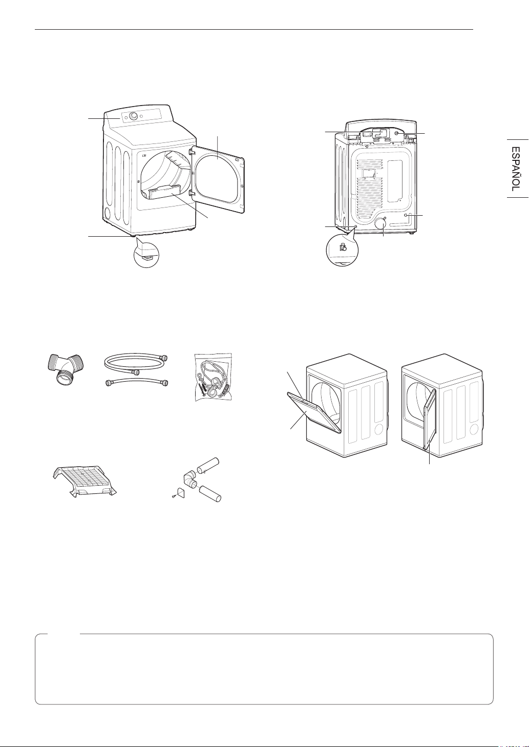
9DESCRIPCIÓN GENERAL DEL PRODUCTO
DESCRIPCIÓN GENERAL DEL PRODUCTO
Partes
Panel de
control
Patas
niveladoras
Puerta
reversible
Ubicación del
cable eléctrico
(Modelos a gas)
Valvula de entrada
de agua
(en algunos
modelos)
Salida del conducto
de escape
Panel de acceso del
bloque terminal
(Modelos eléctricos)
Ubicación de
la toma de gas
(Modelos a gas)
Filtro de
pelusa
Accesorios
Accesorios incluidos
Accesorios opcionales
Conector en "Y"
(modelos de vapor)
Manguera
(modelos de vapor)
Kit de ventilación lateral
(se vende por separado)
N.º de kit: 383EEL9001B
Kit de jación de
seguridad
(en algunos modelos)
Rejilla de secado
(se vende por separado)
kit: 3750EL0001C
Apertura
Puerta de
apertura
superior
Puerta abatible
La función LG EasyLoad™ le permite abrir la puerta de la
secadora desde la parte superior (como la puerta de un canasto
de ropa) cuando carga la secadora, lo que le permite guiar
la ropa hacia el tambor y evitar que se caiga al suelo. Para
descargar la secadora o cargar prendas más voluminosas, utilice
la puerta abatible para un fácil acceso al tambor.
Kit de fijación de seguridad
Este kit opcional ayuda a evitar que la secadora vuelque si los niños se suben a la puerta o si alguien cae sobre la puerta. Se
recomienda la instalación de este kit dependiendo de su situación particular, pero no es obligatoria. Siga las instrucciones de
instalación incluidas con el kit para instalarlo correctamente. Si no instala el kit, guárdelo fuera del alcance de los niños.
NOTA
•
Para su seguridad y con el fin de ampliar la vida útil del producto, utilice solo componentes autorizados. El fabricante no
es responsable del mal funcionamiento del producto ni de accidentes causados por el uso de componentes o piezas no
autorizados y comprados por separado.
•
Las imágenes de esta guía podrían ser diferentes a los componentes y accesorios reales, que están sujetos a cambiar a
discreción del fabricante, sin previo aviso, con fines de mejorar el producto.
Puerta reversible de doble
sentido (en algunos modelos)
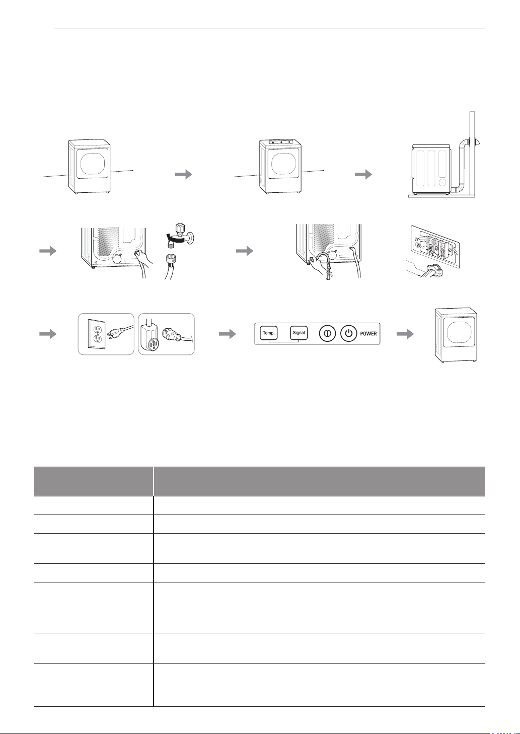
10 INSTALACIÓN
INSTALACIÓN
Descripción general de la instalación
Lea las siguientes instrucciones de instalación en primer lugar, después de comprar este producto o transportarlo a otra ubicación.
Verique y elija la
ubicación adecuada
Conecte la manguera de
entrada (modelos de vapor)
Conecte las secadoras
de gas
Conecte las secadoras
eléctricas
Enchufe el cable de alimentación Prueba de instalación Haga una prueba
de funcionamiento
Secadora de gas Secadora eléctrica
Nivele la secadora
Ventile la secadora
Especificaciones del producto
La apariencia y las especificaciones detalladas en este manual podrían variar, debido a mejoras constantes en el producto.
Modelos de secadoras
DLEX7900*E, DLEX7800*E, DLEX7880*E
DLGX7901*E, DLGX7801*E, DLGX7881*E
Descripción
Secadora a vapor
Requisitoseléctricos
Consulte la etiqueta de datos de servicio para más información.
Requisitosdegas
Gas natural: 4 a 10,5 pulgadas de columna de agua
Gas licuado de petróleo: 8 a 13 pulgadas de columna de agua (solo para los modelos de gas)
Presión máx. de agua
20 a 120 psi (138 a 827 kPa)
Dimensiones
27” (Ancho) X 29 1/2” (Profundidad) X 44 1/4” (Alto), 50 1/4” (Profundidad con la puerta
abierta)
68,6 cm (Ancho) X 75,0 cm (Profundidad) X 112,3 cm (Alto), 127,5 cm (Profundidad con la
puerta abierta)
Peso neto
Secadora de gas: 129,8 lb (58,9 kg)
Secadora eléctrica: 124,8 lb (56,6 kg)
Capacidad de secado
- Ciclo normal
- Ciclo de vapor
IEC 7,3 pies cúbicos (22,5 lb/10,2 kg)
IEC 7,3 pies cúbicos (8 lb/3,6 kg)

11INSTALACIÓN
Requisitosdellugardeinstalación
ADVERTENCIA
¡Lea todas las instrucciones de instalación antes de instalar y operar su secadora! Es importante que revise este manual
por completo antes de instalar y usar su secadora. En las siguientes páginas, se proporcionan instrucciones detalladas con
respecto a las conexiones eléctricas, a las conexiones de gas y a los requisitos de escape.
La instalación requiere:
•
Un lugar que permita la instalación correcta del sistema de escape. La secadora de gas debe tener un escape al exterior.
Consulte la sección Ventilación de la secadora.
•
Una toma de corriente eléctrica conectada a tierra a 2 pies (61 cm) a uno de los lados de la secadora. Consulte la sección
Conexión de secadoras eléctricas.
•
Suelo firme para soportar el peso total de la secadora de 200 lb (90,7 kg). Además, se deberá tener en cuenta el peso combinado
de un posible aparato adicional que lo acompañe.
•
No se puede instalar ningún aparato de combustión en el mismo armario que la secadora.
No utilice la secadora a temperaturas inferiores a 45 °F (7 °C). A temperaturas más bajas, la secadora puede no apagarse al final
de un ciclo automático. Esto puede dar lugar a tiempos de secado más prolongados. La secadora no se debe instalar ni almacenar
en una zona donde quede expuesta al agua o a la intemperie. Consulte los requisitos normativos. Algunos códigos limitan, o no
permiten, la instalación de la secadora en garajes, casas móviles o dormitorios. Comuníquese con el inspector de construcciones
de su localidad.
NOTA
•
Debajo de la secadora en su conjunto, el suelo debe estar nivelado y no debe tener una inclinación superior a 1 pulgada
(2,5 cm). Si la secadora no está nivelada, las prendas no se centrifugarán apropiadamente y es posible que los ciclos de
sensor automático no funcionen correctamente.
•
Para la instalación en un garaje, deberá colocar la secadora a un mínimo de 18 pulgadas (46 cm) por encima del suelo. El
pedestal convencional es de 15 pulgadas (38,1 cm). Debe dejar una separación de 18 pulgadas (46 cm) entre el piso del
garaje y la parte inferior de la secadora.
Espacios libres
Separación para instalación en áreas cerradas o armarios
Se recomienda dejar las siguientes separaciones para esta secadora. Esta secadora se ha evaluado dejando una separación de
1 pulgada (2,5 cm) a ambos lados y en la parte posterior. Se recomienda dejar los espacios libres recomendados por las razones
siguientes:
•
Se debe considerar dejar espacios libres adicionales para facilitar las tareas de instalación y mantenimiento.
•
Es posible que sea necesario dejar espacios libres adicionales para las molduras del techo, el suelo o la pared.
•
Se debe considerar dejar espacios libres adicionales a ambos lados de la secadora para reducir la transmisión de ruido.
Al realizar la instalación en un armario con puerta, debe haber aberturas de ventilación mínimas en la parte superior e inferior de
la puerta. Se permite el uso de puertas de celosía con aberturas de ventilación equivalentes.
•
Además, debe considerarse la separación para un aparato adicional que lo acompañe.
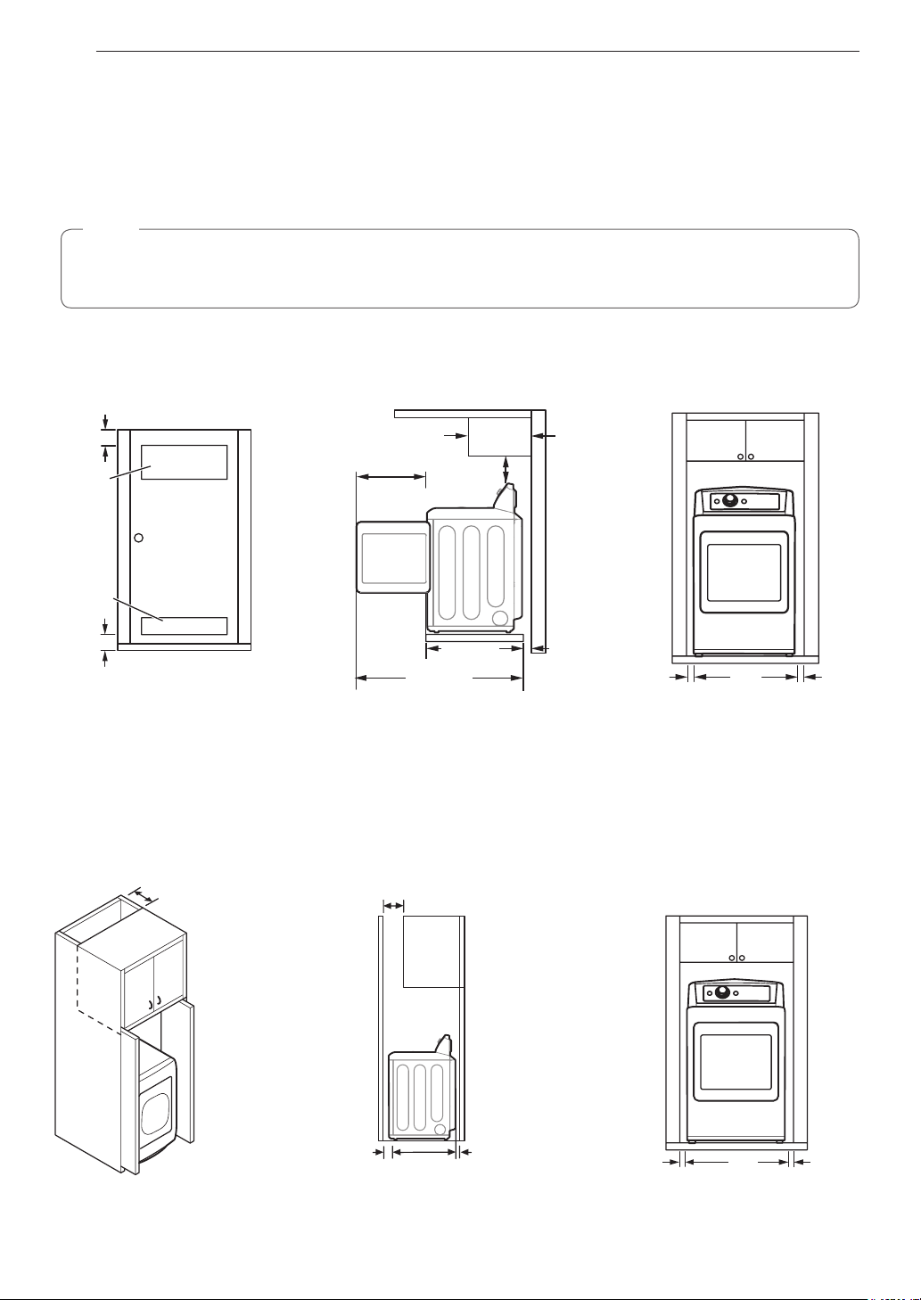
12 INSTALACIÓN
Requisitosdeventilaciónparaarmarios
Los armarios con puertas deben tener ventilación tanto en la parte superior como en la inferior para evitar la acumulación de calor
y humedad dentro del armario. Se debe instalar una abertura de ventilación superior con una apertura mínima de 48 pulgadas
cuadradas (310 cm
2
) a no menos de 6 pies del suelo. Se debe instalar una abertura de ventilación inferior con una apertura
mínima de 24 pulgadas cuadradas (155 cm
2
) a no más de un pie del suelo. Instale rejillas de ventilación o corte la puerta en las
partes superior e inferior para realizar aberturas. También se permite el uso de puertas de celosía con aberturas de ventilación
equivalentes.
NOTA
Se debe dejar al menos un pequeño espacio alrededor de la secadora (o de cualquier otro aparato) para eliminar la
transferencia de vibración de un aparato a otro. Si hubiera bastante vibración, los aparatos podrían hacer ruido o tocarse, con
el consecuente deterioro de la pintura y el incremento del ruido.
Separación para instalación en áreas cerradas o armarios
Requisitos de ventilación
de la puerta del armario
3"
(7,6 cm)
14" máx.*
(35,6 cm)
1"
(2,5 cm)
1"
(2,5 cm)
27"
(68,6 cm)
3"
(7,6 cm)
50
1
/
4
"
(127,5 cm)
29
1
/
2
"
(75,0 cm)
18" min.
(45,7 cm)
21
1
/
4
"
(54 cm)
48 in
2
(310 cm
2
)
24 in
2
(155 cm
2
)
* Separación requerida
** Para la ventilación en las partes lateral o inferior, se permite una separación de 2 pulgadas (5,1 cm).
Separación para instalación en gabinetes
Para instalaciones en gabinetes con puerta, se requieren aberturas de ventilación mínimas en la parte superior del gabinete.
* Separación requerida
7"* (17,8 cm)
7"* (17,8 cm)
5"*
(12,7 cm)
1"
(2,5 cm)
1"*
(2,5 cm)
1"
(2,5 cm)
29
1
/
2
"
(75,0 cm)
27"
(68,6 cm)
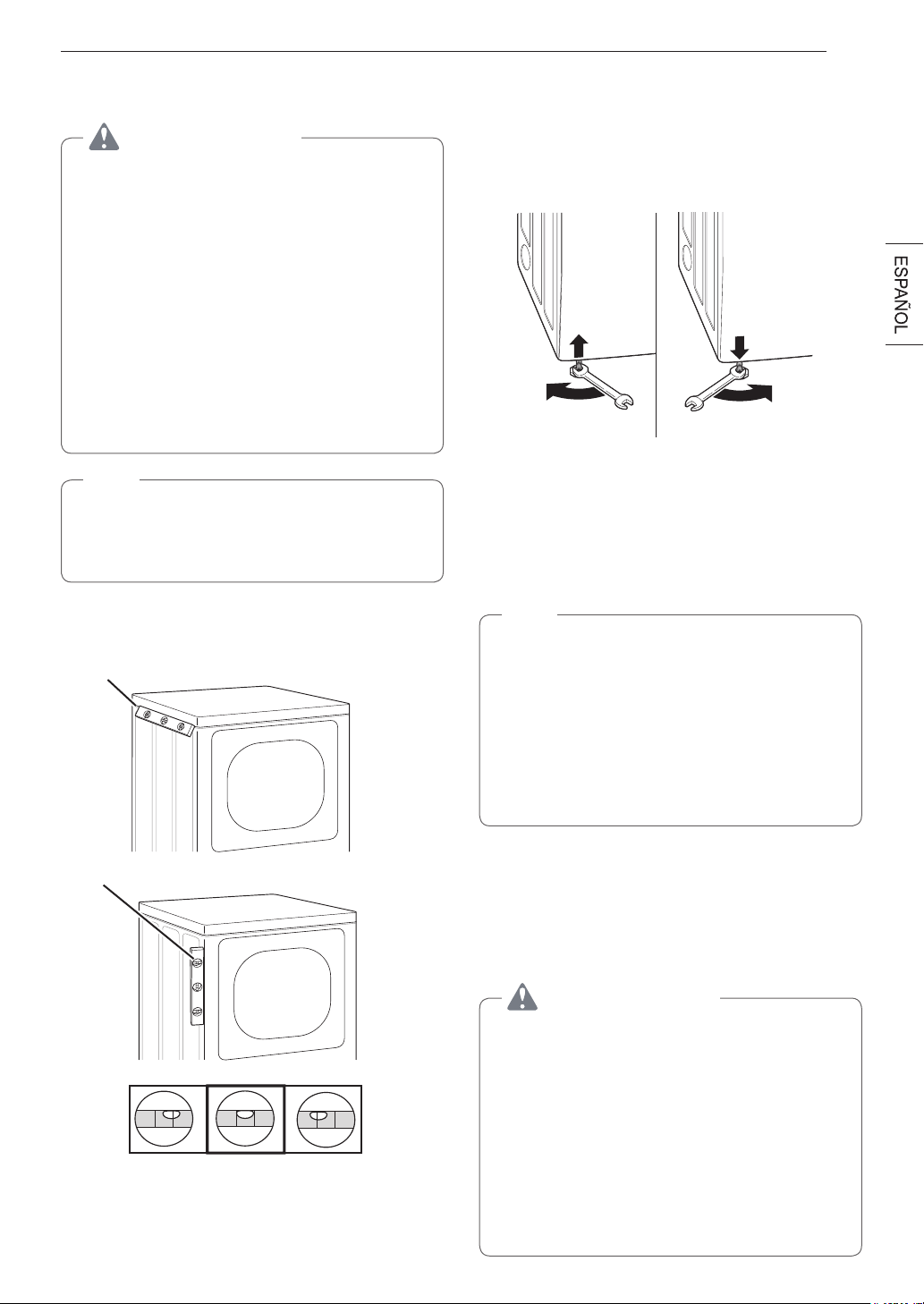
13INSTALACIÓN
Nivelación de la secadora
ADVERTENCIA
Para reducir el riesgo de lesiones personales, cumpla con
todos los procedimientos de seguridad recomendados
por la industria, incluso el uso de guantes con mangas
largas y gafas de seguridad. Si no se cumple con esta
advertencia, se pueden producir lesiones graves o la
muerte.
•
El aparato es pesado. Se necesitan dos o más personas
para la instalación de la secadora. Si no se cumple con
esta advertencia, se pueden producir lesiones graves o
la muerte.
•
Para asegurar que la secadora brinde un desempeño
óptimo de secado, debe estar nivelada. Para minimizar
la vibración, el ruido y los movimientos no deseados, el
piso deberá tener una superficie perfectamente nivelada
y sólida.
NOTA
Ajuste las patas niveladoras solo en la medida necesaria
para nivelar la secadora. Si se extienden las patas
niveladoras más de lo necesario, esto puede causar
vibración de la secadora.
1
Coloque la secadora en su ubicación definitiva. Verifique
que la secadora esté nivelada de lado a lado. Repita
desde la parte frontal a la parte trasera.
Coloque el nivel aquí
Coloque el nivel aquí
No Nivel No NivelNivel
2
Utilice una llave de tuercas ajustable para girar las
patas niveladoras. Desenrosque las patas para levantar
la secadora o enrósquelas para bajarla. Suba o baje
la secadora con las patas niveladoras hasta que se
encuentre nivelada de lado a lado y de adelante hacia
atrás. Asegúrese de que las cuatro patas niveladoras se
encuentran haciendo contacto firme con el piso.
Si instalará la secadora sobre el pedestal opcional, debe
utilizar las patas niveladoras del pedestal para nivelar la
secadora. Las patas niveladoras de la secadora deben estar
completamente retraídas.
Inversión de la puerta
Antesdecomenzar
NOTA
Las llamadas al servicio técnico para invertir la mano de
la puerta no están cubiertas bajo la garantía del producto.
•
El proceso de inversión de puerta para la puerta de
dos direcciones es más complejo que para una puerta
convencional de secadora. Lea atentamente estas
instrucciones antes de comenzar el proceso, para que
usted pueda decidir si debería encargar el trabajo a un
instalador profesional o un técnico.
•
Encontrará también un video de soporte en
http://www.lg.com/us/support/videos/video-tutorials-
view, How to Reverse the Door – LG EasyLoad Dryer.
Herramientasnecesarias
•
Destornillador Phillips
•
Destornillador de punta plana grande
(recomendado
para los tornillos de las bisagras si están apretados o si su
destornillador Phillips está desgastado)
•
Destornilladordepuntaplanapequeño
(para levantar piezas)
ADVERTENCIA
LA PUERTA DE LA SECADORA ES MUY GRANDE
Y PESADA. Si no se siguen las instrucciones a
continuación, se podrían producir daños en la secadora o
en la propiedad o lesiones personales.
•
Para evitar daños en la secadora o en la puerta,
sostenga la puerta con un taburete o una caja que
quepa debajo de la puerta o pida a una persona que lo
asista a soportar el peso de la puerta.
•
Evite que la puerta se caiga para que no se produzcan
daños en la puerta o en el piso.
•
Desenchufe la secadora o corte la energía desde el
disyuntor principal antes de comenzar el procedimiento
de inversión de la puerta.
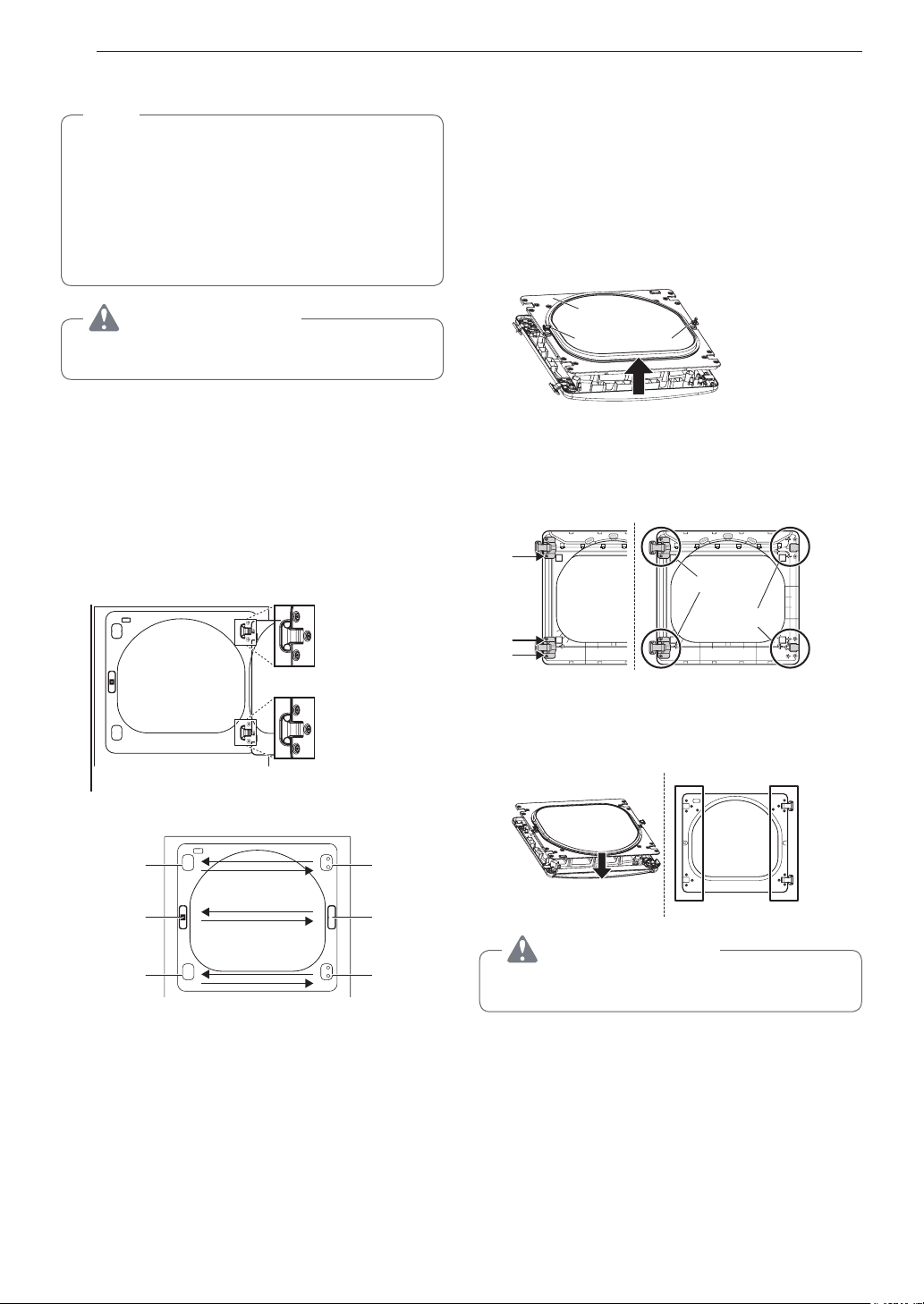
14 INSTALACIÓN
c. Retire la cubierta de la bisagra mediante un suave
movimiento de palanca con un destornillador de
punta plana, cuidando de no rayar la pintura. Gire la
cubierta de la bisagra 180 grados e instálela en el lado
opuesto, donde estaba sujeta la bisagra.
4
Con la puerta colocada sobre una superficie protegida,
retire todos los tornillos de cada lado de la puerta y retire
el panel interior de la puerta con un destornillador de
punta plana. Retire el enganche y la pieza, y llévelas al
lado opuesto.
Enganche
Pieza
Estructura interior
de la puerta
5
Retire los 4 tornillos fijando las bisagras a la estructura
de la puerta. Retire los dos rellenadores de plástico.
Vuelva a instalar las bisagras y los rellenadores en los
lados opuestos a su posición inicial.
Tapa de
cubierta
Montaje de
bisagra
6
Con las bisagras y los rellenadores en la nueva posición,
monte de nuevo el panel interior de la puerta en la
estructura de ésta con los tornillos retirados en el paso 3
anterior.
ADVERTENCIA
Asegúrese de soportar el peso de la puerta antes de
instalar los tornillos de las bisagras.
Instrucciones para la puerta reversible
NOTA
Las instrucciones que aquí se ofrecen son para modificar
la abertura de la puerta de una posición con las bisagras a
la derecha a una posición con las bisagras a la izquierda.
Si la puerta se invirtió y debe hacerlo nuevamente,
siga estas instrucciones con cuidado. Algunas de las
ilustraciones y las referencias de derecha/izquierda
estarán al revés, por lo que debe leer las instrucciones
con sumo cuidado.
ADVERTENCIA
Asegúrese de soportar el peso de la puerta antes de
extraer los tornillos de las bisagras.
Puerta abatible
1
Abra la puerta de costado de manera de poder
acceder a los tornillos de las bisagras.
2
Extraiga los cuatro tornillos de las bisagras
Mientras sostiene a la puerta, extraiga los cuatro tornillos
de las bisagras, dos de cada bisagra. Aparte la puerta:
colóquela de cara al suelo sobre una superficie protegida
para evitar que se dañe la puerta o la superficie de
trabajo.
3
Reverse the components on the cabinet.
Bisagra
Cubierta de la
bisagra
Cubierta de la
bisagra
Mecanismo de
cierre
Cubierta del
agujero del
pestillo
Bisagra
a. Utilice un destornillador Phillips para extraer los dos
tornillos y el mecanismo de cierre del panel frontal del
gabinete.
b. Extraiga la cubierta del agujero del cierre mediante un
suave movimiento de palanca con un destornillador de
punta plana, cuidando de no rayar la pintura. Instale la
cubierta del agujero del cierre en el lado opuesto, de
donde se ha extraído el mecanismo de cierre. Instale
el mecanismo de cierre en la posición de donde
extrajo la cubierta del agujero del pestillo utilizando los
dos tornillos extraídos en el paso a.
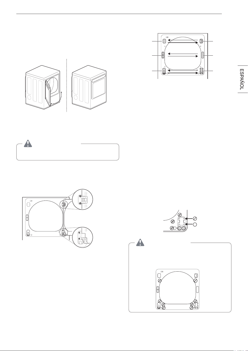
15INSTALACIÓN
7
Reinstale la puerta.
Mientras sujeta la puerta, instálela con los cuatro tornillos
de bisagra retirados en el paso 2. Pruebe el movimiento
de apertura y cierre de la puerta para asegurarse de que
las bisagras y el pestillo están correctamente alineados
y que la puerta abre, cierra y traba correctamente en
ambas direcciones.
Puerta
abatible
Puerta de apertura superior
(en algunos modelos)
ADVERTENCIA
Asegúrese de soportar el peso de la puerta antes de
instalar los tornillos de las bisagras.
DEL GABINETE :
1
Abra la puerta de costado de manera de poder
acceder a los tornillos de las bisagras.
Dos tornillos
grandes
Dos tornillos
pequeños
2
Extraiga los cuatro tornillos de las bisagras
Mientras sostiene a la puerta, extraiga los cuatro tornillos
de las bisagras, dos de cada bisagra. Aparte la puerta:
colóquela de cara al suelo sobre una superficie protegida
para evitar que se dañe la puerta o la superficie de
trabajo.
3
Invierta los componentes del gabinete.
Bisagra
superior
Cubierta de la
bisagra
Bisagra
Mecanismo de
cierre
Cubierta del
agujero del
pestillo
Soporte de
la bisagra
a. Utilice un destornillador Phillips para extraer los dos
tornillos y el mecanismo de cierre del panel frontal del
gabinete.
b. Extraiga la cubierta del agujero del cierre mediante un
suave movimiento de palanca con un destornillador de
punta plana, cuidando de no rayar la pintura. Instale la
cubierta del agujero del cierre en el lado opuesto, de
donde se ha extraído el mecanismo de cierre. Instale
el mecanismo de cierre en la posición de donde
extrajo la cubierta del agujero del pestillo utilizando los
dos tornillos extraídos en el paso a.
c. Retire la cubierta de la bisagra mediante un suave
movimiento de palanca con un destornillador de
punta plana, cuidando de no rayar la pintura. Gire la
cubierta de la bisagra 180 grados e instálela en el lado
opuesto, donde estaba sujeta la bisagra superior.
d. Invierta la bisagra y el soporte de la bisagra de la
parte inferior del gabinete. Extraiga los dos tornillos
del soporte de la bisagra en la parte inferior derecha
y retire el soporte de la bisagra. Extraiga el tornillo
inferior de los dos tornillos que se encuentran detrás
del soporte de la bisagra. NO extraiga el tornillo
superior detrás del soporte de la bisagra. Aparte las
piezas.
PRECAUCIÓN
NO extraiga ninguno de los ocho tornillos del frente del
gabinete (se indican aquí abajo). Si esto se hiciere, se
podrían producir daños en la secadora y podría tener que
llamar al servicio técnico para que repare la secadora.

16 INSTALACIÓN
e. Extraiga los tres tornillos de la bisagra inferior
izquierda. Extraiga la bisagra y vuelva a instalarla en
el lado derecho. El tornillo superior ocupará el agujero
de donde extrajo el tornillo detrás del soporte de la
bisagra en el paso d.
f. Instale el soporte de la bisagra que extrajo en el paso
d en el lado inferior izquierdo colocando primero un
tornillo detrás del soporte de la bisagra.
Cubierta de
la bisagra
Soporte de la
bisagra
Cubierta del
agujero del
pestillo
Mecanismo de
cierre
Bisagra
Cabinet Reversal complete
EN LA PUERTA:
4
Levante la cubierta de la puerta.
Con la puerta apoyada sobre una superficie protegida y
con su parte interior mirando hacia arriba, extraiga los
doce tornillos de la parte interior de la puerta. Levante
con cuidado la cubierta de la puerta con la ayuda de un
destornillador de punta plana pequeño insertado en la
esquina superior (con un círculo aquí abajo).
ADVERTENCIA
Los bordes de la cubierta de la puerta pueden ser filosos.
Tenga cuidado al manipularla o use guantes para evitar
lesiones.
Tapa del
agujero
Doce tornillos
Botón de
bloqueo lateral
5
Intercambie la cerradura de la puerta y la cubierta
ciega.
Extraiga los dos tornillos de la cubierta de la puerta que
sujetan la cerradura de la puerta.
Intercambie la cerradura de la puerta y la cubierta ciega
e instálelas en el lado opuesto del lado de donde las
extrajo.
Tornillo
largo
Tornillos
cortos
Cubierta ciega Cerradura de la puerta
Tirar
Elevar
Quitar cubierta blanca
Retire con un suave movimiento de palanca la tapa del
agujero que se encuentra en el costado de la cubierta de
la puerta e instálela en el agujero del lado opuesto.
Tapa del
agujero
Aparte la cubierta de la puerta.
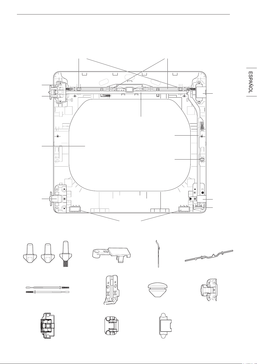
17INSTALACIÓN
6
Invierta los componentes de la parte interior de la puerta.
Ahora retirará e invertirá varios componentes de la parte interior de la puerta. Aquí abajo encontrará un diagrama detallado
con la identificación de la estructura interna y las partes de la puerta. (El diagrama muestra la “vista anterior” de la puerta,
con la distribución predeterminada para una apertura con la bisagra del lado derecho. Luego de seguir estas instrucciones, la
puerta será una imagen en espejo de la ilustración).
Pieza de
relleno de
la bisagra
superior
Barra de bloqueo lateral
Botón de bloqueo lateral
Pieza de
relleno de
la bisagra
inferior
Soporte de
la bisagra
inferior
Topes
Barras de bloqueo interioresBotones de bloqueo superiores
Barra de bloqueo superior
Ensamblaje
de la bisagra
superior
Pivote de
la bisagra
superior
Cristal
Ensamblaje
de la bisagra
inferior
Botones de bloqueo
Ensamblaje de la bisagra superior Pivote de la bisagra superior Pieza de relleno de la bisagra superior
Barras de bloqueo interiores
Pieza de relleno de la bisagra inferior
Soporte de la bisagra inferior
Barra de bloqueo superior
Ensamblaje de la bisagra inferior
Barra de bloqueo
lateral
Tapa del agujero
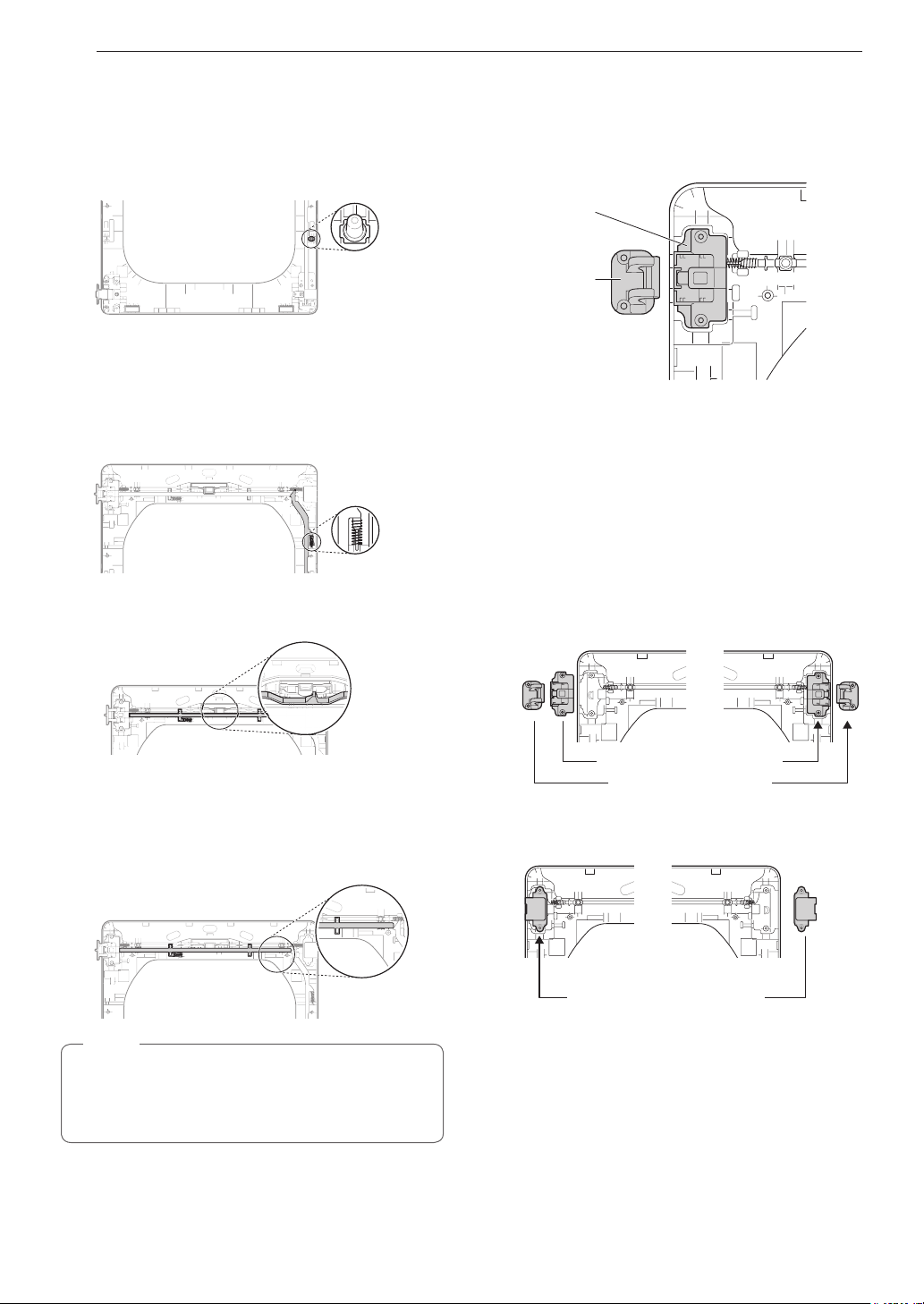
18 INSTALACIÓN
7
Retireelbotóndebloqueodecolorgrisdelcostado
de la puerta.
Asegúrese de extraer el resorte con el botón de bloqueo
y de conservar las dos piezas juntas. Aparte el botón de
bloqueo. No lo mezcle con los botones de bloqueo de la
parte superior de la puerta exterior.
8
Extraigalabarradebloqueolateral.
Extraiga la barra de bloqueo lateral del soporte de la
bisagra inferior levantando el extremo superior de la
barra y deslizándola hacia la parte superior de la puerta.
El resorte debe mantenerse sujeto a la barra de bloqueo.
Aparte la barra de bloqueo.
Resorte
9
Extraigalabarradebloqueosuperior.
a. Deslice la barra de bloqueo hacia la derecha para
extraerla del ensamblaje de la bisagra que se encuentra
en el costado izquierdo.
b. Mientras desliza la barra hacia la derecha, levante el
extremo derecho y retírelo de las guías.
No retire las dos barras de bloqueo interiores y los dos
botones de bloqueo (ver página page 17) ubicadas
debajo de la barra de boqueo superior. NO deben
invertirse.
NOTA
10
Extraiga el pivote de la bisagra superior.
Una vez que haya extraído la barra de bloqueo
superior, el pivote de la bisagra puede extraerse
fácilmente del ensamblaje de la bisagra en la parte
superior izquierda. Apártelo.
Ensamblaje
de la bisagra
superior
Pivote de
la bisagra
superior
11
Inviertaelensamblajedelabisagraylapiezade
relleno de la bisagra superiores.
Retire la pieza de relleno de la bisagra superior (a la
derecha) y apártela.
Con cuidado, levante el ensamblaje de la bisagra
superior (a la izquierda) y sáquelo del marco de la
puerta exterior; use un destornillador de punta plana
pequeño si fuera necesario. Gire el ensamblaje de
la bisagra 180 grados e instálelo en la parte superior
derecha de la puerta exterior. Deberá presionar
firmemente para instalar el ensamblaje de la bisagra.
El pivote de la bisagra extraído en el paso 11 se
instalará más adelante.
Ensamblaje de la bisagra superior
Pivote de la bisagra superior
Ahora, gire la pieza de relleno de la bisagra 180 grados
e instálela en la parte superior izquierda de la puerta.
Pieza de relleno de la bisagra superior

19INSTALACIÓN
12
Vuelvaainstalarlabarradebloqueosuperior.
Gire la barra de bloqueo superior (extraída en el
paso 10) 180 grados en la posición contraria a su
posición original y vuelva a instalarla. El resorte ahora
debe encontrarse hacia la derecha del centro, con el
resorte del costado de la barra orientado hacia la parte
superior de la puerta.
a. Inserte el extremo derecho de la barra de bloqueo
en el ensamblaje de la bisagra derecha. Asegúrese
de que la barra esté alineada con las guías del
panel de la puerta.
b. Baje la barra y colóquela en su posición,
deslizándola y rodeando la manija central, y
asegurándose de alinear la barra de bloqueo con
las guías a lo largo del panel de la puerta. Cuando
la suelte, la barra de bloqueo debe deslizarse
completamente e insertarse en el ensamblaje de la
bisagra de la derecha. Deslice la barra de bloqueo
hacia adelante y hacia atrás para asegurarse de
que esté correctamente colocada en las guías y que
corra con facilidad.
13
Invierta el soporte de la bisagra y el ensamblaje de
la bisagra inferiores.
a. Extraiga el tornillo del soporte de la bisagra inferior
(a la derecha) y retire el soporte de la bisagra.
Apártela. Extraiga los dos tornillos del ensamblaje
de la bisagra inferior de la parte inferior izquierda y
retire el ensamblaje de la bisagra.
b. Gire el ensamblaje de la bisagra inferior 180 grados
e instálelo en el lado derecho utilizando los dos
tornillos extraídos en el paso a.
Ensamblaje de la bisagra inferior
Tornillos
c. Voltee el soporte de la bisagra inferior y suelte las
lengüetas que se encuentran en la parte posterior y
que sujetan la pieza de relleno de la bisagra con el
soporte de la bisagra.
Lengüeta
d. Gire la bisagra 180 grados y vuelva a colocarla en la
parte delantera del soporte de la bisagra orientada
hacia la dirección contraria.
e. Instale el soporte de la bisagra inferior y la pieza de
relleno en el costado izquierdo de la puerta con el
tornillo extraído en el paso a.
Tornillo
14
Instalelabarradebloqueolateral.
Voltee la barra de bloqueo lateral e instálela en el
lado opuesto. Inserte el extremo inferior en la bisagra
izquierda; baje la barra sobre las guías de la puerta al
tiempo que comprime el resorte dentro de la cavidad.
Asegúrese de que la parte superior de la barra de
bloqueo lateral se encuentre al costado de la barra de
boqueo superior y que no se superpongan, de manera
que las dos barras puedan interactuar de la manera
correcta. Si no están alineadas correctamente, la
puerta no funcionará bien.
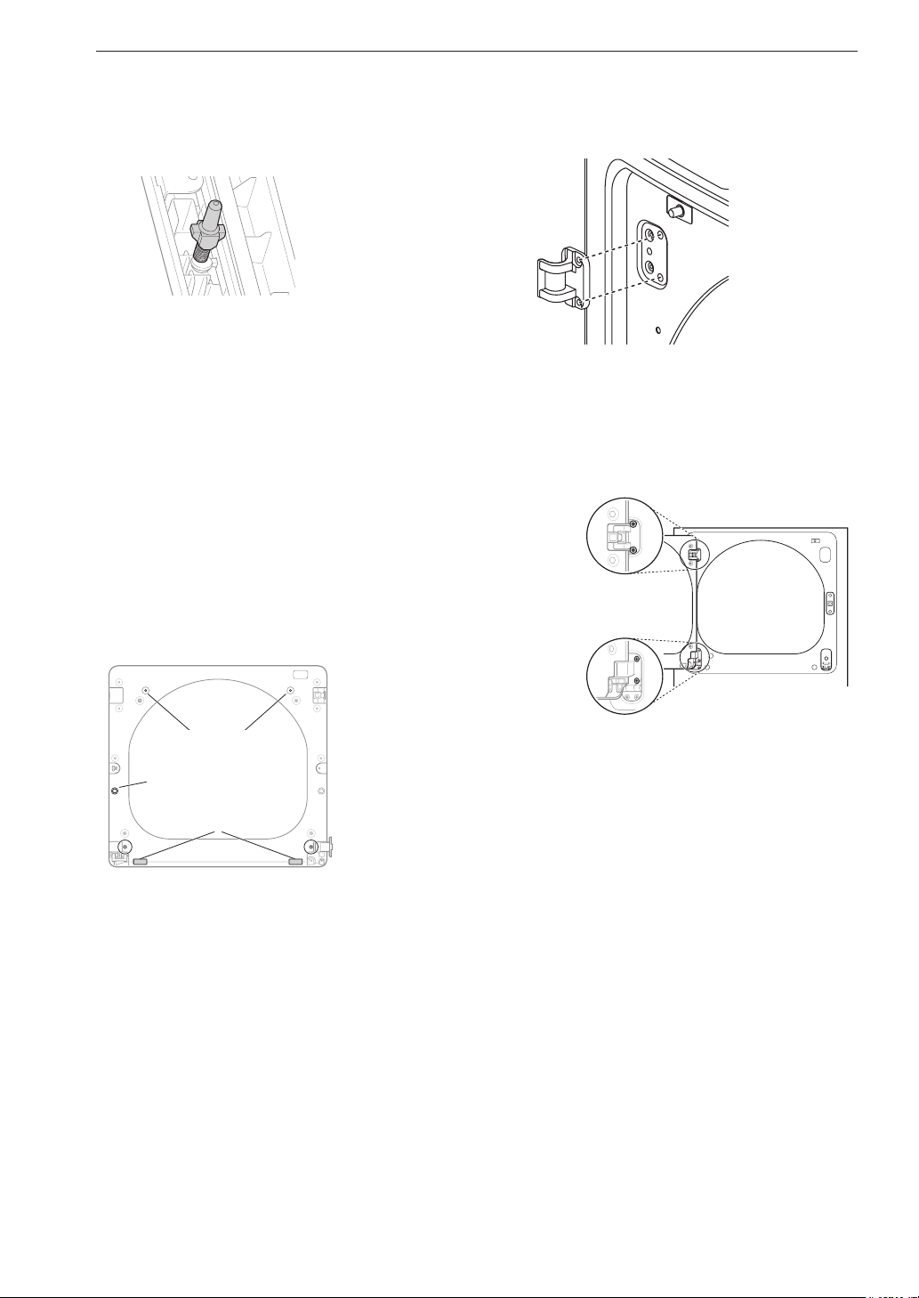
20 INSTALACIÓN
15
Vuelvaainstalarelbotóndebloqueolateral.
Vuelva a instalar el botón de bloqueo lateral extraído
en el paso 7. Coloque el resorte en el centro del
compartimiento e inserte el botón de bloqueo arriba
del resorte.
16
Vuelva a instalar la cubierta de la puerta.
Limpie el cristal de la puerta y de la cubierta de la
cubierta si fuera necesario.
Asegúrese de que los tres botones de bloqueo de color
gris estén colocados correctamente y que las barras
de bloqueo superior y lateral estén bien alineadas en
el lugar donde se encuentran una con la otra. Con
cuidado, baje la cubierta de la puerta y colóquela en
su lugar, alineando los orificios de la cubierta con los
botones de bloqueo de la parte superior y del costado,
y con los topes en la parte inferior. Tenga cuidado de
no desencajar las barras de bloqueo cuando instale
la cubierta de la puerta. Una vez que la cubierta de
la puerta está colocada, fíjela con los 12 tornillos
extraídos en el paso 4. Los diez tornillos similares se
colocan alrededor de la parte superior y los costados
de la cubierta de la puerta. Asegúrese de instalar los
dos tornillos diferentes en el borde inferior, en los
lugares que se indican aquí abajo.
Botones
de bloqueo
Botón de
bloqueo
lateral
Topes
17
Ahora,tomeelpivotedelabisagrasuperiorque
extrajo anteriormente y gírelo 180 grados.
Instalarlabisagraenelladosuperiorizquierdode
la carcasa.
18
Vuelva a instalar la puerta.
Mientras sostiene la puerta, instale los cuatro tornillos
de las bisagras extraídos en el paso 2. Pruebe el
movimiento giratorio de la puerta para asegurarse
de que las bisagras y el pestillo estén correctamente
alineados y que la puerta se abra, se cierre y se trabe
adecuadamente en ambas direcciones.
Dos
tornillos
grandes
Dos
tornillos
pequeños
Mientras sostiene la puerta, instale los dos bisagra
pequeños extraídos en el paso 2. Pruebe el
movimiento giratorio de la puerta para asegurarse
de que las bisagras y el pestillo estén correctamente
alineados y que la puerta se abra, se cierre y se trabe
adecuadamente en ambas direcciones.
Si la puerta no funciona correctamente, retírela y
abra la tapa para comprobar el correcto montaje y
alineación de las barras de bloqueo y los botones de
enclavamiento.
Los botones de enclavamiento deben orientarse
correctamente y funcionar con suavidad. Las barras
de bloqueo deben estar en la posición adecuada y no
superponerse en el punto de contacto. (Consulte los
pasos 15-17.)
Si está dañado, o si la puerta no funciona tras el
montaje, póngase en contacto con el centro de
asistencia telefónica al 1-800-243-0000.
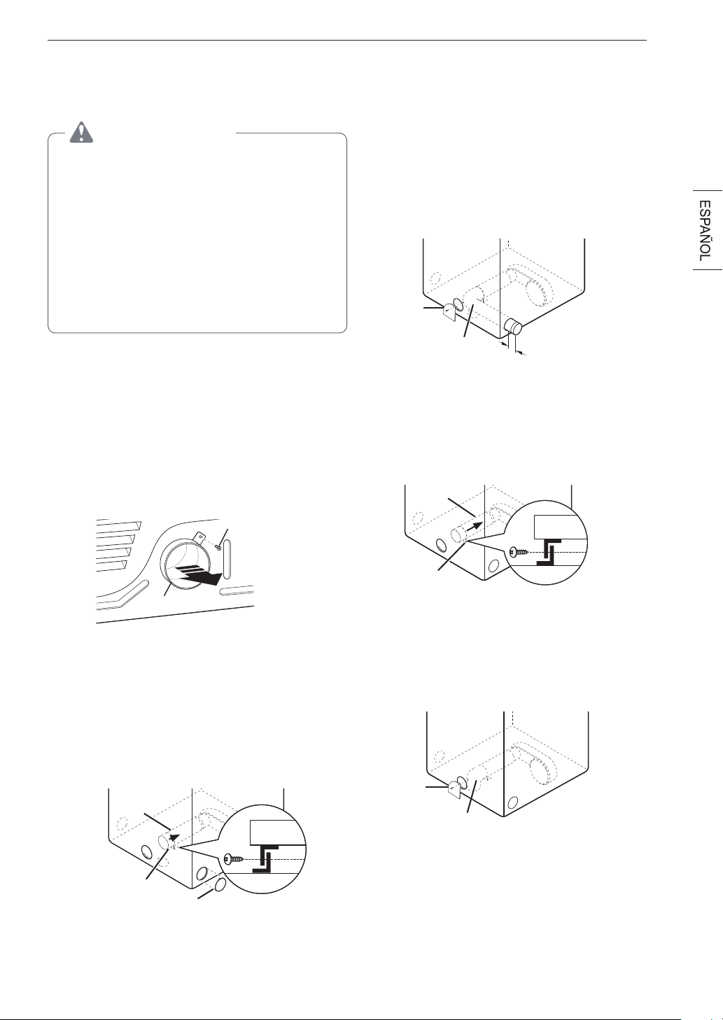
21INSTALACIÓN
Instalación del kit de
ventilación lateral
ADVERTENCIA
•
Utilice material para ventilación de metal pesado.
•
No utilice conductos de plástico ni de lámina de metal.
•
Limpie los conductos antiguos antes de instalar esta
secadora.
•
Para reducir el riesgo de lesiones personales,
cumpla con todos los procedimientos de seguridad
recomendados por la industria, incluso el uso de
guantes con mangas largas y gafas de seguridad.
•
Si no se cumplen todas las advertencias de seguridad
de este manual, se podrían producir daños en la
propiedad, lesiones personales o la muerte.
Su nueva secadora está equipada de fábrica para ventilar
hacia la parte trasera. También puede configurarse para
ventilar hacia la parte inferior o lateralmente (la ventilación
lateral derecha no está disponible en los modelos de gas).
Puede adquirir un kit adaptador, número de pieza
383EEL9001B, de su distribuidor LG. Este kit contiene
los componentes de conducto necesarios para cambiar la
ubicación de la ventilación de la secadora.
1
Retire el tornillo de retención del conducto de escape
trasero. Saque el conducto de escape.
Tornillo de retención
Conducto de escape
trasero
Opción 1: Ventilación lateral
2
Apriete las lengüetas de la tapa del agujero preperforado
y quítela cuidadosamente para lograr la abertura de
ventilación deseada (la ventilación lateral derecha no
está disponible en los modelos de gas). Introduzca
a presión el conducto adaptador en la carcasa del
ventilador y fíjelo a la base de la secadora como se
indica.
Conducto
adaptador
Soporte
Tapa de agujero
preperforado
3
Ensamble un codo de 4 pulgadas (10,2 cm) a la
siguiente sección de conducto de 4 pulgadas (10,2 cm)
y asegure todas las conexiones con cinta adhesiva
para conductos. Asegúrese de que el extremo macho
del codo apunte hacia FUERA de la secadora. Inserte
el ensamblaje del codo/conducto a través de la
abertura lateral e introdúzcalo a presión en el conducto
adaptador. Asegúrelo en su lugar con cinta adhesiva
para conductos. Asegúrese de que el extremo macho
del conducto sobresalga 1½ pulgadas (3,8 cm) para
conectar el resto de los conductos. Coloque la tapa en la
parte trasera de la secadora con el tornillo provisto.
Tapa
Codo
1
½
"
(3,8 cm)
Opción 2: Ventilación inferior
2
Introduzca a presión el conducto adaptador en la carcasa
del ventilador y fíjelo a la base de la secadora como se
indica.
Conducto
adaptador
Soporte
3
Inserte el codo de 4 pulgadas (10,2 cm) a través de la
abertura trasera e introdúzcalo a presión en el conducto
adaptador. Asegúrese de que el extremo macho del codo
apunte hacia abajo a través del orificio ubicado en la
parte inferior de la secadora. Asegúrelo en su lugar con
cinta adhesiva para conductos. Coloque la tapa en la
parte trasera de la secadora con el tornillo provisto.
Tapa
Codo

22 INSTALACIÓN
Ventilación de la secadora
ADVERTENCIA
Para reducir el riesgo de incendio o explosión, descargas
eléctricas, daños a la propiedad, lesiones personales o la
muerte al usar este aparato, siga las precauciones básicas
de seguridad, incluso lo siguiente:
•
No aplaste ni haga colapsar los conductos.
El
incumplimiento de estas instrucciones podrá producir un
incendio o la muerte.
•
Nopermitaquelosconductosseapoyensobre
objetos puntiagudos ni entren en contacto con ellos.
El incumplimiento de estas instrucciones podrá producir un
incendio o la muerte.
•
Sirealizaunaconexiónaconductosexistentes,
asegúresedequeseanlosadecuadosydequeestén
limpios antes de instalar la secadora.
El incumplimiento
de estas instrucciones podrá producir un incendio o la
muerte.
•
El sistema de ventilación debe respetar los códigos
de construcción locales.
El incumplimiento de estas
instrucciones podrá producir un incendio o la muerte.
•
Las secadoras de gas DEBEN tener escape al exterior.
El incumplimiento de estas instrucciones podrá producir un
incendio o la muerte.
•
Use únicamente conductos de metal rígidos,
semirrígidos o flexibles de 4 pulgadas (10,2 cm) dentro
del gabinete de la secadora o para ventilación al
exterior.
El incumplimiento de estas instrucciones podrá
producir un incendio o la muerte.
•
Para reducir el riesgo de incendio, combustión o
acumulación de gases combustibles, NO dirija el escape
de la secadora hacia un área cerrada o no ventilada,
como desvanes, muros, cielos rasos, cámaras,
chimeneas, conductos de gas o espacios ocultos de
un edificio.
El incumplimiento de estas instrucciones podrá
producir un incendio o la muerte.
•
Para reducir el riesgo de incendio, NO realice el escape
de la secadora con conductos de plástico ni de lámina
metálica fina.
El incumplimiento de estas instrucciones
podrá producir un incendio o la muerte.
•
El conducto de escape deberá tener 4 pulgadas (10,2 cm)
de diámetro sin obstrucciones. El conducto de escape
deberá mantenerse lo más corto posible. Asegúrese
de limpiar los conductos antiguos antes de instalar su
secadora nueva.
El incumplimiento de estas instrucciones
podrá producir un incendio o la muerte.
•
Se recomienda el uso de conductos rígidos,
semirrígidos o flexibles entre la secadora y la pared.
Todoslosconductosmetálicosdetransiciónqueno
sean rígidos deben estar aprobados por UL. El uso
de otros materiales para el conducto de transición
afectará el tiempo de secado.
El incumplimiento de estas
instrucciones podrá producir un incendio o la muerte.
•
NO utilice tornillos para chapa metálica ni ningún
otrotipodesujetadoresqueseextiendandentrodel
conducto y puedan atrapar pelusa, y, así, reducir
la eficiencia del sistema de escape. Asegure todas
las uniones con cinta adhesiva para conductos.
El
incumplimiento de estas instrucciones podrá producir un
incendio o la muerte.
•
No exceda las limitaciones de longitud de los
conductosrecomendadasqueseindicanenelcuadro.
El incumplimiento de estas instrucciones podrá producir
tiempos de secado prolongados, un incendio o la muerte.
•
No se proporcionan los conductos con la secadora.
Debe obtener los conductos necesarios en su localidad.
La campana de ventilación deberá tener reguladores de
tiro con bisagras para prevenir una contracorriente de
aire cuando no se use la secadora.
El incumplimiento de
estas instrucciones podrá producir un incendio o la muerte.
•
La longitud total del conducto metálico flexible no
deberá superar los 8 pies (2,4 m).
•
En Canadá, solo se deberán usar conductos flexibles de
lámina de metal, si fueran necesarios, específicamente
identificados por el fabricante para su uso con el
aparato.
En los Estados Unidos, solo se deberán usar
conductos flexibles de lámina de metal, si fueran necesarios,
específicamente identificados por el fabricante para su uso
con el aparato y que cumplan el Esquema para conductos
de transición de secadoras (Outline for Clothes Dryer
Transition Duct), Sección 2158A.
Conductos
Tipo de tapa de
pared
Cantidad de
codos de
90°
Longitud máxima de
conducto metálico
rígido de 4 pulgadas
(10,2 cm) de diám.
Recomendado
4"
(10,2 cm)
4"
(10,2 cm)
0 65 pies (19,8 m)
1 55 pies (16,8 m)
2 47 pies (14,3 m)
3 36 pies (11,0 m)
4 28 pies (8,5 m)
Solo para uso en
instalaciones con
conductos cortos
2
1
/
2
"
(6,35 cm)
0 55 pies (16,8 m)
1 47 pies (14,3 m)
2 41 pies (12,5 m)
3 30 pies (9,1 m)
4 22 pies (6,7 m)
NOTA
Reste 6 pies (1,8 m) por cada codo adicional. No use más
de cuatro codos de 90°.
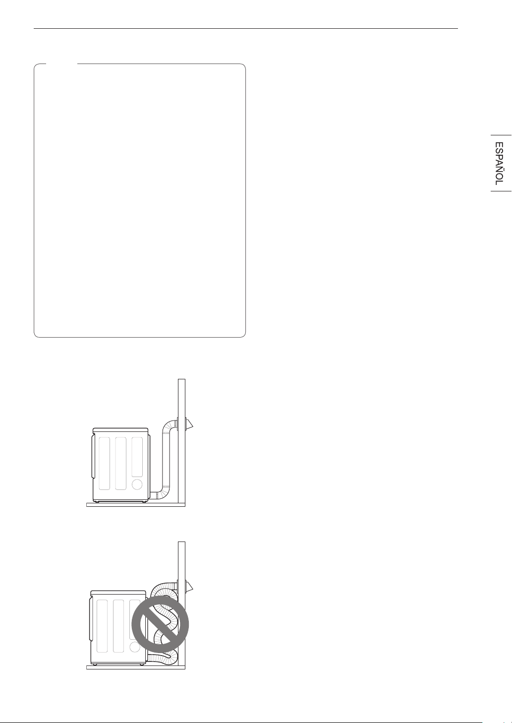
23INSTALACIÓN
Recorrido y conexión de los conductos
NOTA
Siga las pautas a continuación para maximizar el
rendimiento de secado, para reducir la acumulación de
pelusa y la condensación en los conductos. Los conductos
y las conexiones NO están incluidos y deben adquirirse
por separado.
•
Use conductos metálicos rígidos, semirrígidos o
flexibles de 4 pulgadas (10,2 cm) de diámetro.
•
El tendido del conducto de escape debe ser lo más
corto posible.
•
Use la menor cantidad de conexiones de codos posible.
•
El extremo macho de cada sección del conducto de
escape debe apuntar hacia fuera de la secadora.
•
Use cinta adhesiva para conductos en todas las
uniones de los conductos.
•
Aísle los conductos que se pasen por áreas sin
calefacción para reducir la condensación y la
acumulación de pelusa en las superficies de los
conductos.
•
La garantía de la secadora no cubre los sistemas de
escape instalados de manera inadecuada. La garantía
de la secadora no cubrirá las fallas o el servicio técnico
de la secadora derivados de dichos sistemas de
escape.
Ventilación correcta
Ventilación incorrecta
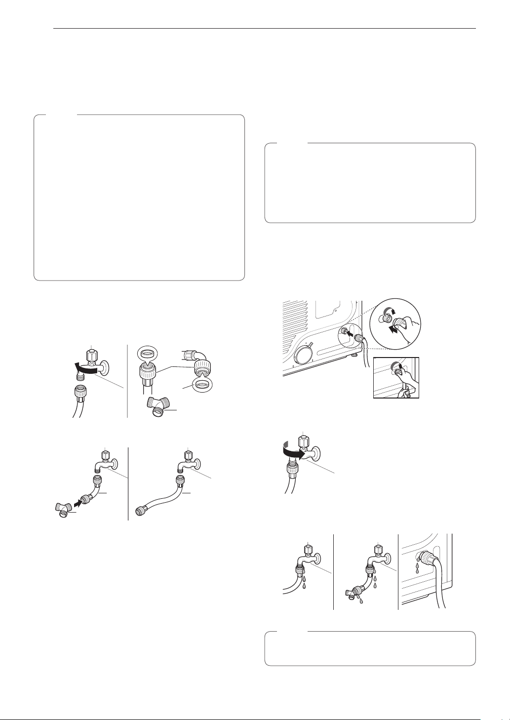
24 INSTALACIÓN
Conexión de la manguera de entrada
(modelos de vapor)
La secadora debe conectarse al grifo de agua fría mediante
una manguera de suministro de agua nueva. No utilice
mangueras viejas.
NOTA
•
La presión del suministro de agua debe ser de entre
20 y 120 psi (138 a 827 kPa).
•
No dañe ni fuerce la rosca cuando conecte la manguera
de entrada a la válvula.
•
Si la presión de agua es superior a 800 kPa, debe
instalarse una válvula reductora de presión.
•
Revise las condiciones de la manguera de manera
periódica y reemplácela si fuera necesario.
•
Reemplace las mangueras de entrada después de
5 años de uso para reducir el riesgo de falla en la
manguera.
•
Anote las fechas de instalación o de reemplazo en las
mangueras para futuras consultas.
1
Revise el sello de goma de la manguera de entrada. Se
proporcionan dos sellos de goma con cada manguera
de entrada. Se utilizan para evitar las pérdidas de agua.
Asegúrese de que la conexión con el grifo de agua fría
sea hermética.
Conector
de la
manguera
Sello de
goma
Conector en "Y"
2
Verifique el tipo de instalación.
Conector en "Y"
Manguera
larga
Man-
guera
corta
CON LAVADORA SIN LAVADORA
Apriete bien todas las conexiones de las mangueras de
suministro de agua a mano y luego ajuste otros 2/3 de
vueltaconpinzas.
CON LAVADORA: En el caso de conectar la secadora en el
mismogrifoquelalavadora.
a. Cierre el grifo de agua fría y quite la manguera de la
lavadora.
b. Conecte la manguera corta al conector en "Y" usando uno
de los sellos de goma.
c. Conecte el otro extremo de la manguera corta al grifo de
agua fría.
d. Conecte la manguera larga de la secadora en un extremo
del conector en "Y" y conecte la manguera de la lavadora
en el otro extremo.
SIN LAVADORA: Si la secadora no comparte el grifo de
agua fría con una lavadora.
a. Conecte el extremo recto de la manguera larga al grifo de
agua fría.
NOTA
•
Antes de conectar la línea de agua a la secadora,
evacue varios galones de agua en un desagüe o en
un cubo. Esto evitará que algunas partículas extrañas
como arena y sarro tapen la válvula de entrada de la
secadora.
•
No ajuste de más. Podría dañar los acoplamientos.
3
Conecte la manguera a la secadora. Conecte la
manguera de suministro de agua a la válvula de entrada
de la secadora a mano y luego ajuste otros 2/3 de vuelta
con pinzas.
Asegúrese de que las mangueras no estén plegadas ni
aplastadas.
4
Abra el grifo de agua fría.
5
Verifique que no haya fugas en el conector en "Y" (si se
utiliza) ni en ninguna otra manguera.
NOTA
•
Si hubiera fugas, cierre el grifo de agua, quite la
manguera y revise el estado del sello de goma.
25INSTALACIÓN
Conexión de secadoras de gas
ADVERTENCIA
Para reducir el riesgo de incendio o explosión, descargas
eléctricas, daños a la propiedad, lesiones personales o la
muerte al usar este aparato, siga las precauciones básicas
de seguridad.
Requisitosdesuministrodegas
•
Esta secadora está configurada de fábrica para uso con
gas natural (NG). Puede convertirse para uso con gas
propano (LP). La presión de gas no debe superar las
8 pulgadas (20,3 cm) de columna de agua para el gas
natural ni las 13 pulgadas (33 cm) para el LP.
•
Un técnico calificado de mantenimiento o de la compañía
de gas debe conectar la secadora al suministro de gas.
Si no se cumplen estas instrucciones, se podrá producir
un incendio, una explosión o la muerte.
•
Aísle la secadora del sistema de suministro de gas
cerrando su válvula de corte manual individual durante
las pruebas de presión del suministro de gas a
presiones mayores de 1/2 psi (3.5 kPa).
•
Requisitosdelalíneadesuministro:Sucuartode
lavado debe tener una línea rígida de suministro de
gas para la secadora. En los Estados Unidos, se DEBE
instalar una válvula de corte manual individual a una
distancia de, por lo menos, 6 pies (1,8 m) de la secadora,
de acuerdo con el Código Nacional de Gas Combustible
ANSI Z223.1 o el código canadiense de instalación de
gas CSA B149.1. Se debe instalar un tapón de tubo de
1/8 pulgadas (0,3 cm) NPT.
Si esto no se cumple, se podrá
producir una explosión, un incendio o la muerte.
•
Si se usa una tubería rígida, la tubería rígida debe ser de
½ pulgada IPS. Si es aceptable según los códigos y las
ordenanzaslocales,ycuandoseaaceptablesegúnsu
compañía de gas, se pueden usar tuberías aprobadas
de 3/8 pulgadas (1 cm) cuando las longitudes sean
menores de 20 pies (6,1 m). Se deben usar tuberías más
grandes si las longitudes exceden los 20 pies (6,1 m).
Si esto no se cumple, se podrá producir una explosión, un
incendio o la muerte.
•
Conecte la secadora al tipo de gas indicado en la placa
de identificación.
Si esto no se cumple, se podrá producir
una explosión, un incendio o la muerte.
•
Para evitar la contaminación de la válvula de gas,
purgue el aire y el sedimento del suministro de gas
antes de conectar el suministro de gas a la secadora.
Antes de ajustar la conexión entre el suministro de
gasylasecadora,purgueelairehastaquesedetecte
olor de gas.
Si esto no se cumple, se podrá producir una
explosión, un incendio o la muerte.
•
NO use una llama abierta para inspeccionar si hay fugas
de gas. Use un fluido anticorrosivo para detección
de fugas.
Si esto no se cumple, se podrá producir una
explosión, un incendio o la muerte.
•
Solo utilice una nueva línea de suministro de gas
certificada por AGA o CSA (de conformidad con la
Norma para Conectores para Aparatos de Gas, ANSI
Z21.24•CSA6.10)cononectoresflexiblesdeacero
inoxidable.
•
Ajuste bien todas las conexiones de gas.
Si esto no se
cumple, se podrá producir una explosión, un incendio o la
muerte.
•
Utilice cinta de teflón o un compuesto para conexión
de tuberías insoluble al gas propano (LP) en todas las
roscas de las tuberías.
Si esto no se cumple, se podrá
producir una explosión, un incendio o la muerte.
•
NO intente desensamblar la secadora; todo desmontaje
requieredelaatenciónylasherramientasdeun
técnicoounacompañíademantenimientoautorizado
y calificado.
Si no se cumple esta advertencia, se puede
producir un incendio, una explosión o la muerte.
Requisitoseléctricosparamodelosde
gas únicamente
•
Enningunacircunstanciacorteoquiteeltercerborne
(de conexión a tierra) del cable de alimentación.
Si no
se cumple esta advertencia, se puede producir un incendio,
una explosión o la muerte.
•
Por motivos de seguridad personal, esta secadora debe
estar conectada a tierra adecuadamente.
Si no se cumple
esta advertencia, se puede producir un incendio, una
explosión o la muerte.
•
Esta secadora se debe enchufar a una toma de corriente
conectadaatierrade120VCA,de60Hzprotegidapor
un fusible o cortacircuitos de 15 amperios.
Si no se
cumple esta advertencia, se puede producir un incendio,
una explosión o la muerte.
•
En caso de contar con una toma de corriente de pared
estándar de 2 patas, es su responsabilidad y obligación
reemplazarlaporunatomadecorrientede3patas
con su debida conexión a tierra.
Si no se cumple esta
advertencia, se puede producir un incendio, una explosión o
la muerte.
Plug dryer into a
Connection
Gas Supply
Shut
Valve
Plug
AGA/CSA-Cer
Stainless Steel Flexible
Connector
Enchufe la secadora en una toma de
corriente de 3 patas de 120 V CA,
60Hz, conectada a tierra.
ADVERTENCIA
PELIGRODEDESCARGAELÉCTRICA
Si no se observan las advertencias de seguridad, pueden
producirse lesiones graves o la muerte.
Esta secadora está equipada con un enchufe de tres
clavijas con conexión a tierra a fin de brindar protección
contra descargas eléctricas y debe conectarse
directamente a un receptáculo de tres terminales con una
conexión a tierra adecuada. No corte ni quite la clavija de
conexión a tierra de este enchufe.
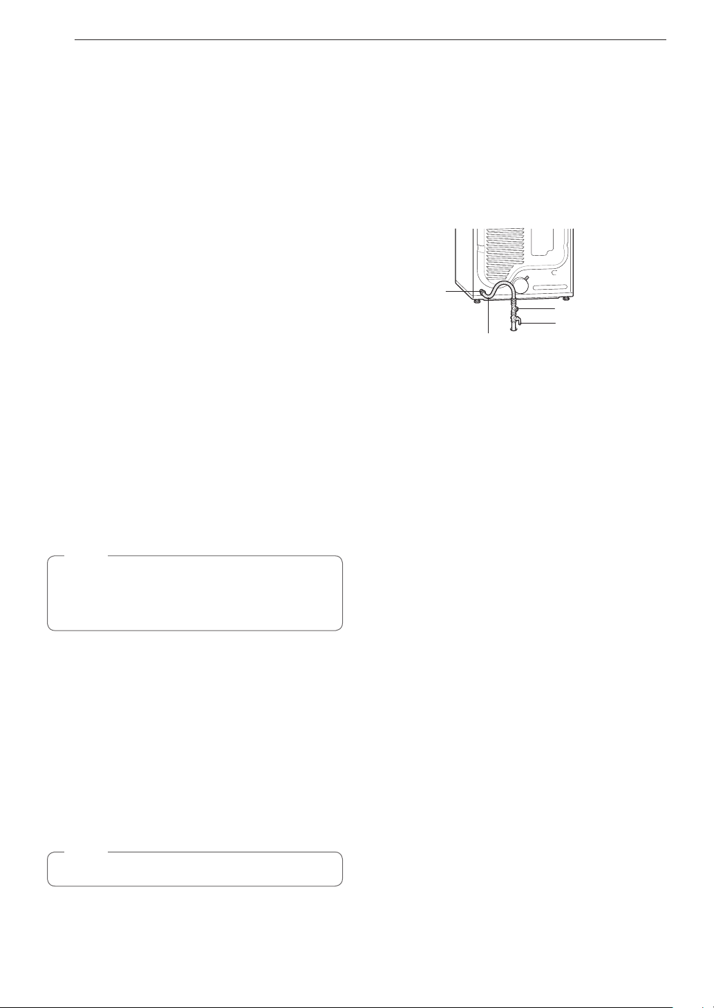
26 INSTALACIÓN
Conexión del suministro de gas
•
Lainstalaciónyelmantenimientodebenserrealizados
por un instalador, una agencia de mantenimiento o una
compañía de gas calificados.
Si esto no se cumple, se
podrá producir una explosión, un incendio o la muerte.
•
Utilice únicamente un conector flexible de acero
inoxidable nuevo y un conector certificado por AGA
nuevo.
Si esto no se cumple, se podrá producir una
explosión, un incendio o la muerte.
•
Se debe instalar una válvula de corte de gas a una
distancia máxima de 6 pies (1,8 m) de la secadora.
Si
esto no se cumple, se podrá producir una explosión, un
incendio o la muerte.
•
La secadora está configurada de fábrica para uso
congasnatural.Asegúresedequelasecadoraesté
equipadaconlaboquillaparaquemadorcorrectaparael
tipodegasqueseusará(gasnaturalopropano).
Si esto
no se cumple, se podrá producir una explosión, un incendio
o la muerte.
•
Si fuera necesario, un técnico calificado deberá instalar
laboquillacorrecta(paraelkitdeboquillaparaLP,
númerodelapiezaparapedidos383EEL3002D)yse
deberá tomar nota de este cambio en la secadora.
Si
esto no se cumple, se podrá producir una explosión, un
incendio o la muerte.
•
Sedebenrealizartodaslasconexionessegúnlos
códigos y las regulaciones locales.
Si esto no se cumple,
se podrá producir una explosión, un incendio o la muerte.
•
Las secadoras de gas DEBEN tener escape al exterior.
Si esto no se cumple, se podrá producir una explosión, un
incendio o la muerte.
NOTA
Esta secadora está configurada de fábrica para uso con
gas natural (NG). Si la secadora se utilizará con gas
propano (LP), un técnico calificado deberá realizar la
conversión.
1
Asegúrese de que el suministro de gas al cuarto de
lavado se encuentre APAGADO y de que la secadora
esté desenchufada. Confirme que el tipo de gas
disponible en su cuarto de lavado sea el adecuado para
la secadora.
2
Quite la tapa de envío de la conexión de gas que se
encuentra en la parte trasera de la secadora. Tenga
cuidado de no dañar la rosca del conector de gas al
quitar la tapa de envío.
3
Conecte la secadora al suministro de gas de su cuarto de
lavado mediante un conector flexible de acero inoxidable
nuevo con una conexión de 3/8 pulgadas NPT.
NOTA
NO use conectores viejos.
4
Ajuste bien todas las conexiones entre la secadora y el
suministro de gas de su cuarto de lavado.
5
Abra el suministro de gas de su cuarto de lavado.
6
Verifique que no haya fugas de gas en ninguna de
las conexiones de las tuberías (tanto interiores como
exteriores) mediante un fluido anticorrosivo para
detección de fugas.
7
Proceda a realizar la ventilación de la secadora.
Conexión de
gas de 3/8"
NPT
Conector exible de acero
inoxidable certicado por
AGA/CSA
Tapón de tubo de 1/8" NPT
Válvula de corte del
suministro de gas
Instalaciones en lugares de gran
altitud
La capacidad de BTU para esta secadora está certificada por
AGA para elevaciones por debajo de los 10,000 pies.
Si instalará su secadora a una elevación superior a los
10,000 pies, la compañía de gas o un técnico calificado
deberán cambiar la capacidad del equipo.

27INSTALACIÓN
Conexión de secadoras
eléctricas
Requisitoseléctricosparamodelos
eléctricos únicamente
ADVERTENCIA
Para ayudar a evitar incendios, descargas eléctricas,
lesiones graves o la muerte, el cableado y la descarga
a tierra deben cumplir con la última edición del Código
Eléctrico Nacional, ANSI/NFPA 70 y todas las regulaciones
locales correspondientes. Comuníquese con un electricista
calificado para que revise el cableado y los fusibles de su
casa para asegurarse de que su casa posee la energía
eléctrica adecuada para que funcione la secadora.
•
Esta secadora debe estar conectada a un sistema de
cableado de metal permanente con conexión a tierra o
se debe tender un conductor para la conexión a tierra
delequipoconlosconductoresdelcircuitoysedebe
conectar al terminal o al cable de tierra del aparato.
Si
esto no se cumple, se podrá producir una explosión, un
incendio o la muerte.
•
Lasecadoratienesupropiobloquedebornes,que
debe conectarse a un circuito individual monofásico
de240VCA,de60Hz,protegidoporunfusiblede
30 amperios (el circuito debe tener protección por
fusible a ambos terminales de la línea). EL SERVICIO
ELÉCTRICODELASECADORADEBESERDELA
MÁXIMA CLASIFICACIÓN DE VOLTAJE INDICADA EN
LA PLACA DE IDENTIFICACIÓN. NO CONECTE LA
SECADORA A UN CIRCUITO DE 110, 115 O 120 VOLTIOS.
Si no se cumplen estas instrucciones, se podrá producir un
incendio, una explosión o la muerte.
•
Si el circuito derivado de la secadora tiene una longitud
de 15 pies (4,5 m) o menos, use cable homologado
porUL(UnderwritersLaboratories)N.°10AWG(solo
alambredecobre)osegúnlorequieranloscódigos
locales. Si supera los 15 pies (4,5 m), use cable
homologadoporUL(UnderwritersLaboratories)
N.°8AWG(soloalambredecobre)osegúnlorequieran
las leyes locales. Disponga de suficiente dotación de
cableado, de manera de poder mover la secadora de su
ubicación normal cuando sea necesario.
Si esto no se
cumple, se podrá producir una explosión, un incendio o la
muerte.
•
NOseproveeelcableflexibledealimentaciónque
conectaelreceptáculodelaparedyelbloquedebornes
de la secadora. El cable de conexión flexible y el calibre
del alambre deben cumplir con los códigos locales
y con las instrucciones indicadas en las siguientes
páginas.
Si no se cumplen estas instrucciones, se podrá
producir un incendio, una explosión o la muerte.
•
No modifique el enchufe ni el cable interno provistos con la
secadora.
•
La secadora deberá conectarse a una toma de corriente de
4 agujeros.
•
Si el enchufe no coincide con la toma de corriente, un
electricista calificado deberá instalar una toma de corriente
adecuada.
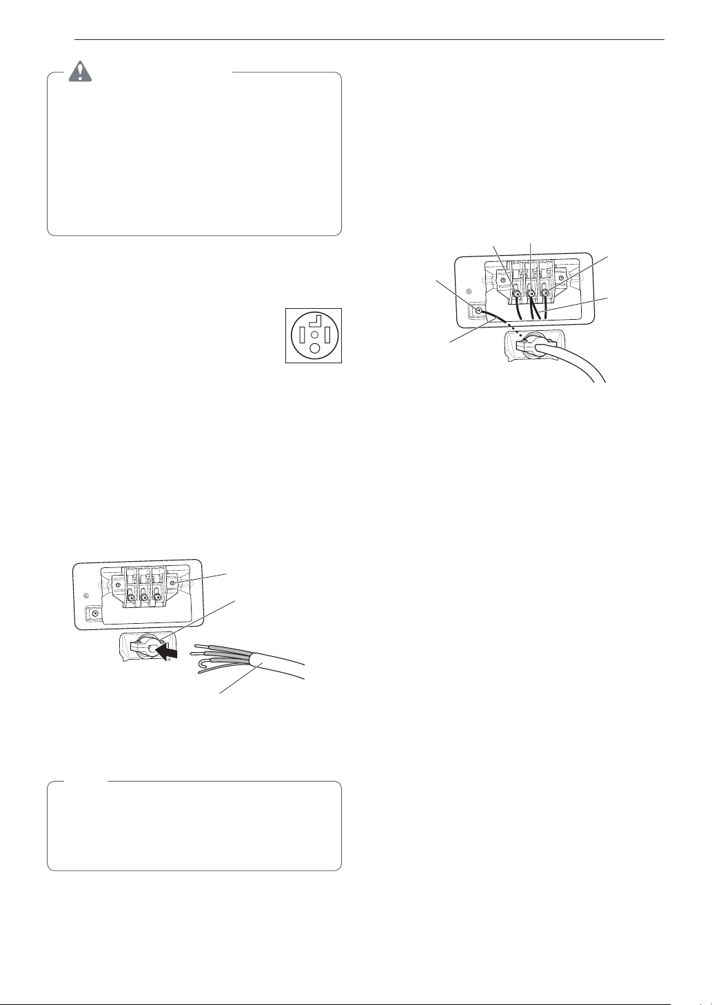
28 INSTALACIÓN
ADVERTENCIA
Conecte el cable de alimentación al bloque de bornes.
Cada alambre de color debe conectarse al tornillo del
mismo color. El alambre del color indicado en el manual
se conecta al tornillo del bloque del mismo color. Si no
se siguen estas instrucciones, se podría producir un
cortocircuito o una sobrecarga.
La conexión a tierra a través del conductor neutro está
prohibido para: (1) nuevas instalaciones de circuito
derivado, (2) áreas donde los códigos locales prohíban
una conexión a tierra a través del conductor neutro.
Cable de alimentación de cuatro hilos
•
Se requiere un aliviador de tensión
homologado por UL.
•
Use un cable de alimentación de 30 amperios,
240 voltios, de 4 hilos homologado por UL
con un conductor de cobre N.° 10 AWG como
mínimo y terminales de bucle cerrado o de
horquilla con extremos doblados hacia arriba.
1
Quite la cubierta de acceso al bloque de bornes
localizada en la parte superior trasera de la secadora.
2
Instale un aliviador de tensión homologado por UL en el
orificio por el que pasa el cable de alimentación.
3
Pase un cable de alimentación de 30 amperios,
240 voltios, de 4 hilos homologado por UL con un
conductor de cobre N.° 10 AWG como mínimo por el
aliviador de tensión.
Bloque de bornes
Aliviador de tensión
homologado por UL
Cable de alimentación de
4 hilos homologado por UL
4
Transfiera el alambre de conexión a tierra de la secadora
desde detrás del tornillo de conexión a tierra de color
verde al tornillo central del bloque de bornes.
NOTA
Esta secadora se proporciona con el alambre neutro
conectado a tierra. Este alambre conectado a tierra de
color blanco DEBE MOVERSE al terminal neutro si se
utilizará un cable de 4 hilos o si se prohíbe la conexión a
tierra a través del conductor neutro.
5
Conecte los dos conductores vivos del cable de
alimentación a los tornillos exteriores del bloque de
bornes.
6
Conecte el alambre neutro de color blanco al tornillo
central del bloque de bornes.
7
Conecte el alambre de conexión a tierra del cable de
alimentación al tornillo de conexión a tierra de color
verde.
8
Ajuste bien todos los tornillos.
9
Reinstale la cubierta de acceso al bloque de bornes.
Vivo
(rojo)
Neutro
(blanco)
Vivo
(negro)
Tornillo de
conexión
a tierra
Alambre de conexión
a tierra del cable de
alimentación
Alambre
blanco movido
del tornillo de
conexión a
tierra
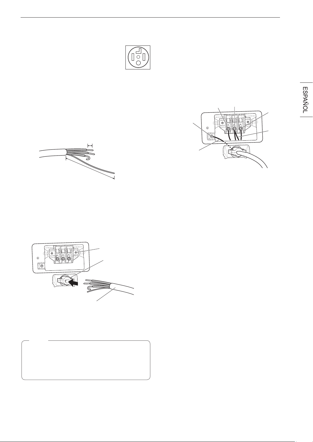
29INSTALACIÓN
Conexión directa de cuatro hilos
•
Se requiere un aliviador de tensión
homologado por UL.
•
Use un cable conductor de cobre de 4 hilos
homologado por UL N.° 10 AWG como
mínimo. Deje un mínimo de 5 pies (1,5 m)
de longitud de cable para poder retirar y
reinstalar la secadora.
1
Retire 5 pulgadas (12,7 cm) de la cubierta exterior
del alambre. Retire 5 pulgadas (12,7 cm) del material
aislante del alambre de conexión a tierra. Corte
aproximadamente 1½ pulgadas (3,8 cm) de los otros tres
alambres y quite 1 pulgada (2,5 cm) del material aislante
de cada uno. Doble los extremos de los tres alambres
más cortos en forma de gancho.
Alambre de
conexión a tierra
1" (2,5 cm)
5"
(12,7 cm)
2
Quite la cubierta de acceso al bloque de bornes
localizada en la parte superior trasera de la secadora.
3
Instale un aliviador de tensión homologado por UL en el
orificio por el que pasa el cable de alimentación.
4
Pase el cable de alimentación de cobre de 4 hilos N.° 10
AWG como mínimo que preparó en el paso 1 por el
aliviador de tensión.
Bloque de bornes
Aliviador de tensión
homologado por UL
Cable de alimentación de
4 hilos homologado por UL
5
Transfiera el alambre de conexión a tierra de la secadora
desde detrás del tornillo de conexión a tierra de color
verde al tornillo central del bloque de bornes.
NOTA
Esta secadora se proporciona con el alambre neutro
conectado a tierra. Este alambre conectado a tierra de
color blanco DEBE MOVERSE al terminal neutro si se
utilizará un cable de 4 hilos o si se prohíbe la conexión a
tierra a través del conductor neutro.
6
Conecte los dos conductores vivos del cable de
alimentación a los tornillos exteriores del bloque de
bornes.
7
Conecte el alambre neutro de color blanco al tornillo
central del bloque de bornes.
8
Conecte el alambre de conexión a tierra del cable de
alimentación al tornillo de conexión a tierra de color
verde.
9
Ajuste bien todos los tornillos.
10
Reinstale la cubierta de acceso al bloque de bornes.
Vivo
(rojo)
Neutro
(blanco)
Vivo
(negro)
Tornillo de
conexión
a tierra
Alambre de conexión
a tierra del cable de
alimentación
Alambre
blanco
movido del
tornillo de
conexión a
tierra
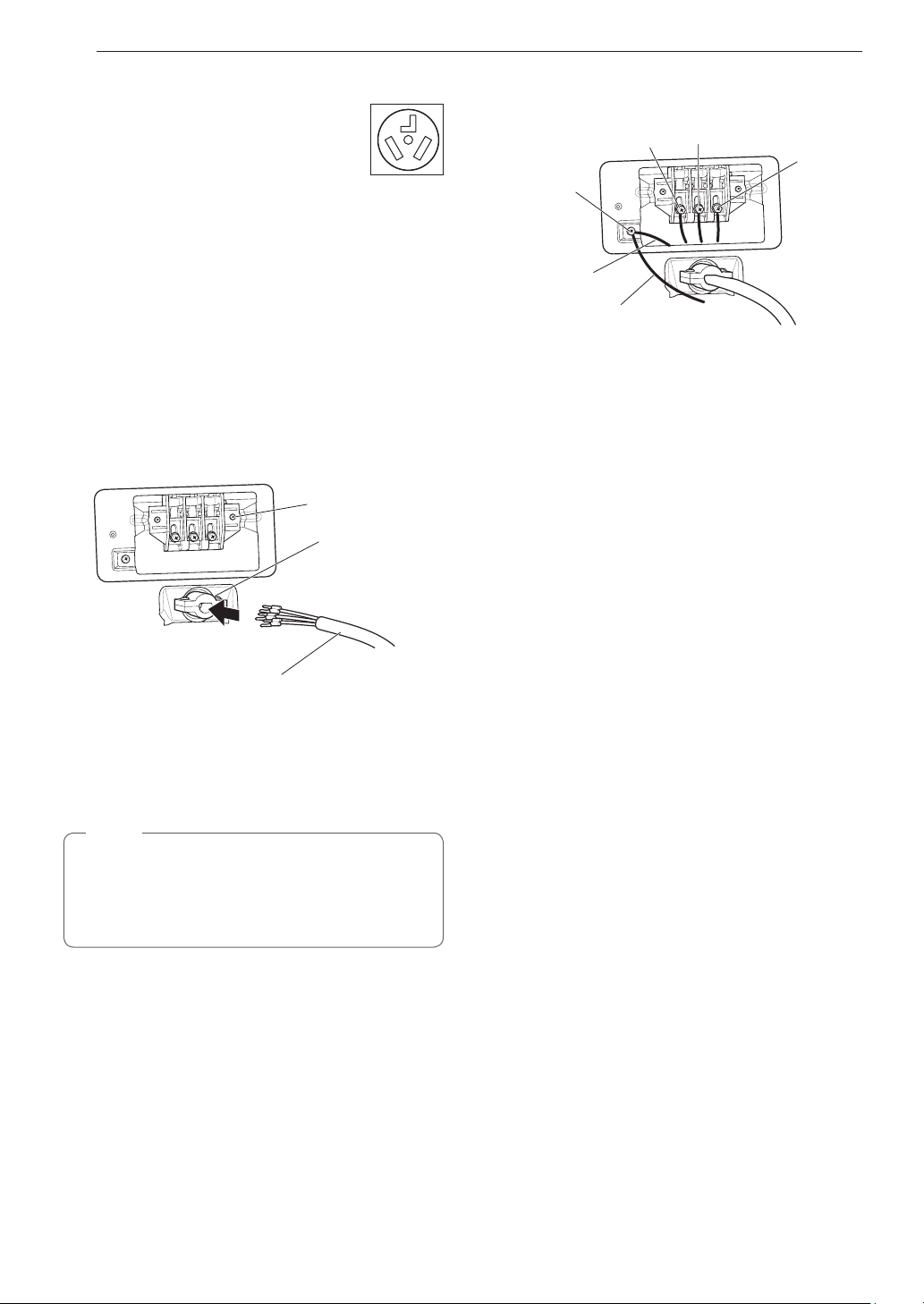
30 INSTALACIÓN
Cable de alimentación de tres hilos
•
NO se permite una conexión de 3 hilos en
construcciones nuevas posteriores al 1 de
enero de 1996.
•
Se requiere un aliviador de tensión homologado por UL.
•
Use un cable de alimentación de 30 amperios, 240 voltios,
de 3 hilos homologado por UL con un conductor de cobre
N.° 10 AWG como mínimo y terminales de bucle cerrado o
de horquilla con extremos doblados hacia arriba.
1
Quite la cubierta de acceso al bloque de bornes
localizada en la parte superior trasera de la secadora.
2
Instale un aliviador de tensión homologado por UL en el
orificio por el que pasa el cable de alimentación.
3
Pase un cable de alimentación de 30 amperios,
240 voltios, de 3 hilos homologado por UL con un
conductor de cobre N.° 10 AWG como mínimo por el
aliviador de tensión.
Bloque de bornes
Aliviador de tensión
homologado por UL
Cable de alimentación de
3 hilos homologado por UL
4
Conecte los dos conductores vivos (negro y rojo) del
cable de alimentación a los tornillos exteriores del bloque
de bornes.
5
Conecte el alambre neutro (blanco) al tornillo central del
bloque de bornes.
NOTA
La secadora se proporciona con el alambre neutro
conectado a tierra. Si se utilizará un cable de 3 hilos, y
su uso está permitido, asegúrese de que el alambre de
conexión a tierra neutro de color blanco se conecte al
tornillo de conexión a tierra de color verde.
6
Conecte el cable de conexión a tierra exterior (si así lo
requieren los códigos locales) al tornillo de conexión a
tierra de color verde.
7
Ajuste bien todos los tornillos.
8
Reinstale la cubierta de acceso al bloque de bornes.
Vivo
(rojo)
Neutro
(blanco)
Vivo
(negro)
Tornillo de
conexión a
tierra
Alambre de conexión a tierra
externo (si lo requieren los
códigos locales)
Alambre blanco
del arnés de
cableado de la
secadora
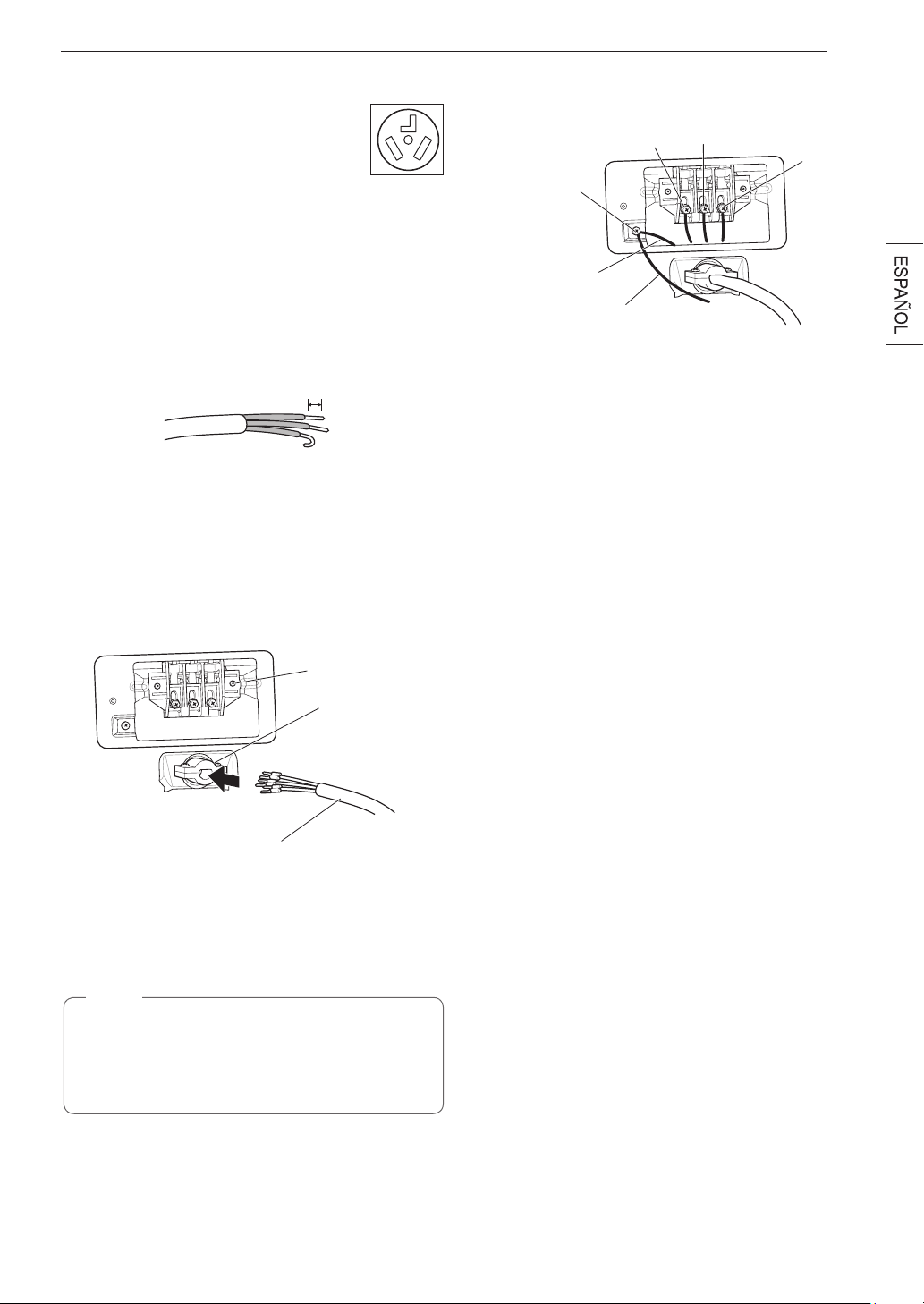
31INSTALACIÓN
Conexión directa de tres hilos
•
NO se permite una conexión de 3 hilos en
construcciones nuevas posteriores al 1 de
enero de 1996.
•
Se requiere un aliviador de tensión homologado por UL.
•
Use un cable conductor de cobre de 3 hilos homologado por
UL N.° 10 AWG como mínimo. Deje un mínimo de 5 pies
(1,5 m) de longitud de cable para poder retirar e instalar la
secadora.
1
Retire 3½ pulgadas (8,9 cm) de la cubierta exterior del
alambre. Pele 1 pulgada (2,5 cm) del material aislante de
cada alambre. Doble los extremos de los tres alambres
en forma de gancho.
1" (2,5 cm)
2
Quite la cubierta de acceso al bloque de bornes
localizada en la parte superior trasera de la secadora.
3
Instale un aliviador de tensión homologado por UL en el
orificio por el que pasa el cable de alimentación.
4
Pase el cable de alimentación de 3 hilos conductores de
cobre N.° 10 AWG como mínimo que preparó en el paso
1 por el aliviador de tensión.
Bloque de
bornes
Aliviador de tensión
homologado por UL
Cable de alimentación de
3 hilos homologado por UL
5
Conecte los dos conductores vivos (negro y rojo) del
cable de alimentación a los tornillos exteriores del bloque
de bornes.
6
Conecte el alambre neutro (blanco) al tornillo central del
bloque de bornes.
NOTA
La secadora se proporciona con el alambre neutro
conectado a tierra. Si se utilizará un cable de 3 hilos, y
su uso está permitido, asegúrese de que el alambre de
conexión a tierra neutro de color blanco se conecte al
tornillo de conexión a tierra de color verde.
7
Conecte el cable de conexión a tierra exterior (si así lo
requieren los códigos locales) al tornillo de conexión a
tierra de color verde.
8
Ajuste bien todos los tornillos.
9
Reinstale la cubierta de acceso al bloque de bornes.
Vivo
(rojo)
Neutro
(blanco)
Vivo
(negro)
Tornillo de
conexión a
tierra
Alambre de conexión a tierra
externo (si lo requieren los
códigos locales)
Alambre blanco
del arnés de
cableado de la
secadora
Revisión final de la instalación
Una vez que haya completado la instalación de la secadora y
esta se encuentre en su ubicación definitiva, verifique si funciona
correctamente realizando las siguientes pruebas y la Prueba de
instalación (Revisión de conductos) de la siguiente página.
Prueba de calentamiento de la
secadora
MODELOS DE GAS
Cierre la puerta de la secadora, presione el botón
POWER
para encenderla e inicie el equipo en un ajuste de calor.
Cuando la secadora inicie, el dispositivo de ignición deberá
encender el quemador principal.
MODELOSELÉCTRICOS
Cierre la puerta de la secadora, presione el botón
POWER
para encenderla e inicie el equipo en un ajuste de calor. El aire
de escape deberá estar tibio después de que la secadora haya
funcionado durante 3 minutos.
Revisióndelujodeaire
El funcionamiento efectivo de la secadora requiere de un flujo de
aire adecuado. La adecuación del flujo de aire puede medirse
evaluando la presión estática. La presión estática del conducto
de escape se puede medir con un manómetro, colocado en el
conducto de escape a aproximadamente 2 pies (60,9 cm) de
distancia de la secadora. La presión estática del conducto de
escape no debe superar las 0,6 pulgadas (1,5 cm). Se debe
revisar la secadora mientras está funcionando sin carga.
Revisión de nivelado
Una vez que la secadora se encuentre en su ubicación
definitiva, vuelva a revisar que esté nivelada. Asegúrese de
que está nivelada de adelante hacia atrás y de lado a lado,
y de que las cuatro patas niveladoras estén firmemente
asentadas en el piso.
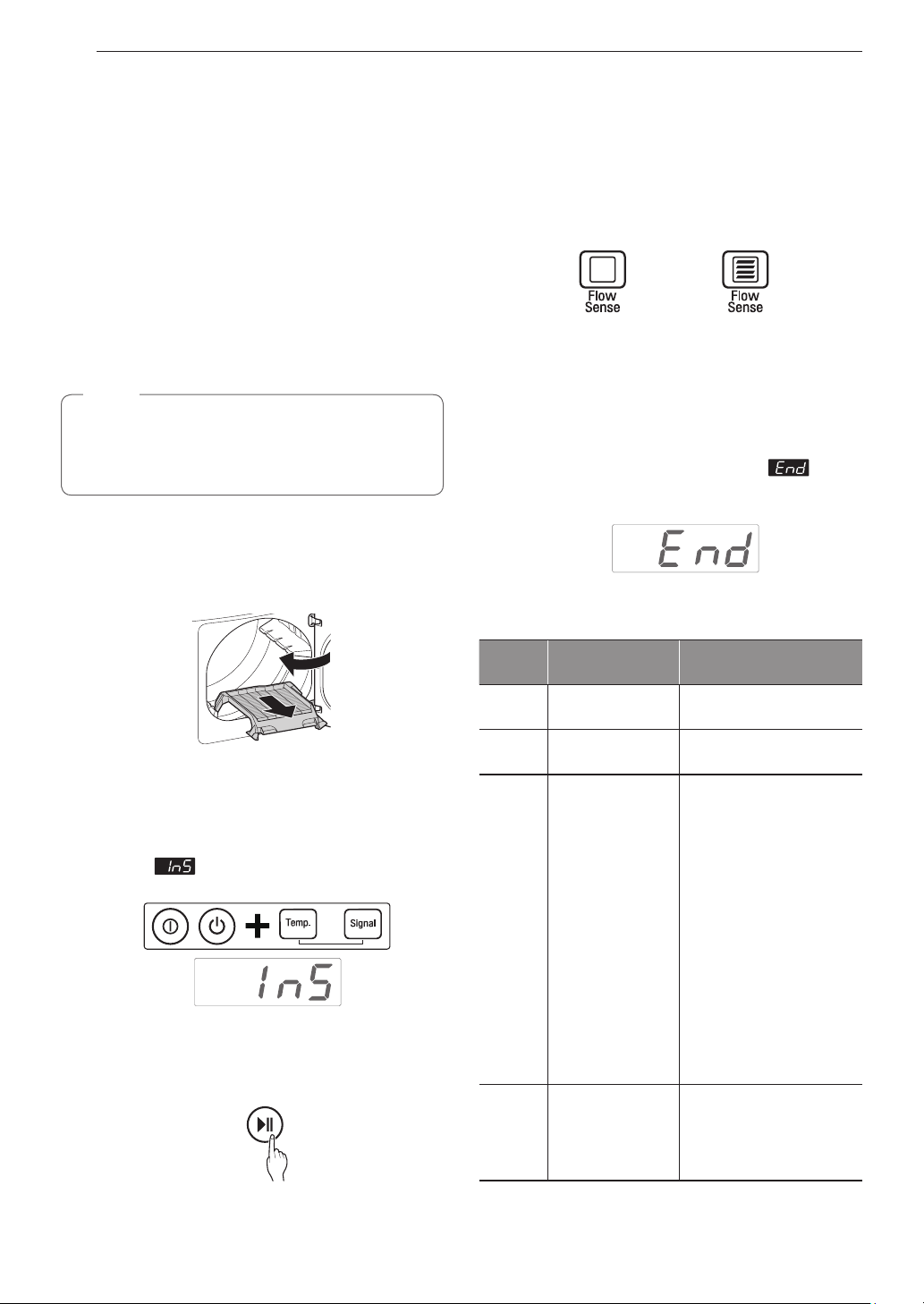
32 INSTALACIÓN
Prueba de instalación
(Revisión de conductos)
Después de completar la instalación de la secadora, haga esta
prueba para asegurarse de que las condiciones del sistema de
escape sean las adecuadas para el funcionamiento correcto
de la secadora. Esta prueba debe realizarse para indicarle si
existe algún problema grave en el sistema de escape de su
casa.
•
Su secadora cuenta con Flow Sense™, un sistema
innovador que detecta automáticamente los bloqueos y las
restricciones en los conductos de la secadora. Mantener
los conductos sin acumulación de pelusa y sin restricciones
le permitirá secar la ropa más rápido y reducir el uso de
energía.
NOTA
La secadora debe estar fría antes de comenzar esta
prueba. Si la secadora se calentó durante la instalación,
ejecute el ciclo AIR DRY durante unos minutos para
reducir la temperatura interna.
Para activar la prueba de instalación:
1
Retire la rejilla de secado y la documentación, y
cierre la puerta.
No cargue nada en el tambor para hacer esta prueba, ya
que podría influir en la precisión de los resultados.
2
Pulse mantenga pulsados el botón
Encendido(Power),yluegopulseymantenga
pulsado Temp.(Temp.) y Spitido(Signal) más de 3
Segundos.
Esta secuencia de botones activa el test de instalacion.
El codigo aparecerá en la pantalla de
visualizacion si la activacion se ha realizado con exito.
3
Presione el botón START/PAUSE.
La secadora iniciará la prueba, que durará cerca de
2 minutos. Se encenderá el calor y se medirán las
temperaturas en el tambor.
4
Verifiquelapantallaparaverlosresultados.
Durante el ciclo de prueba, observe la pantalla de
Flow Sense™ en el panel de control. Si cuando termina
el ciclo no se observan barras, el sistema de escape está
en condiciones adecuadas. Si el sistema de escape está
notoriamente restringido, el icono mostrará cuatro barras.
Si existen otros problemas, estos se indicarán con
códigos de error. Consulte la página siguiente para ver
más detalles sobre los códigos de error y sus soluciones.
SIN BARRAS:
ADECUADO
CUATRO BARRAS:
RESTRINGIDO
Cuatro barras indican que el sistema de escape está
notoriamente restringido. Haga revisar el sistema de
inmediato, ya que el funcionamiento será deficiente.
5
Fin del ciclo.
Al final del ciclo de prueba, se visualizará . El
ciclo de prueba terminará y la secadora se apagará de
forma automática después de una breve pausa.
•
Verifiqueelcódigodeerrorantesdellamaralservicio
técnico
Código
de error
Causas posibles Soluciones
tE1 o tE2
•
Falla del sensor
de temperatura.
•
Apague la secadora y
llame al servicio técnico.
HS
•
Falla del sensor
de humedad.
•
Apague la secadora y
llame al servicio técnico.
PS o PF
o nP
•
El cable de
alimentación de la
secadora eléctrica
no está conectado
correctamente
o el suministro
eléctrico de la
casa no es el
correcto.
•
Se ha quemado el
fusible de la casa,
se ha disparado
el disyuntor o ha
habido un corte de
energía.
•
Verifique el suministro
de energía o la conexión
del cable de alimentación
con el bloque de bornes.
Consulte la sección
Conexión de secadoras
eléctricas
de este manual
para obtener instrucciones
detalladas.
•
Restablezca el disyuntor
o reemplace el fusible. No
aumente la capacidad del
fusible.
Si el problema es una
sobrecarga del circuito,
solicite los servicios de un
electricista calificado.
gAS
•
El suministro o
servicio de gas se
ha desconectado.
(Solo para los
modelos de gas).
•
Confirme que la llave de
gas de la casa y la llave de
gas de la secadora están
completamente abiertas.
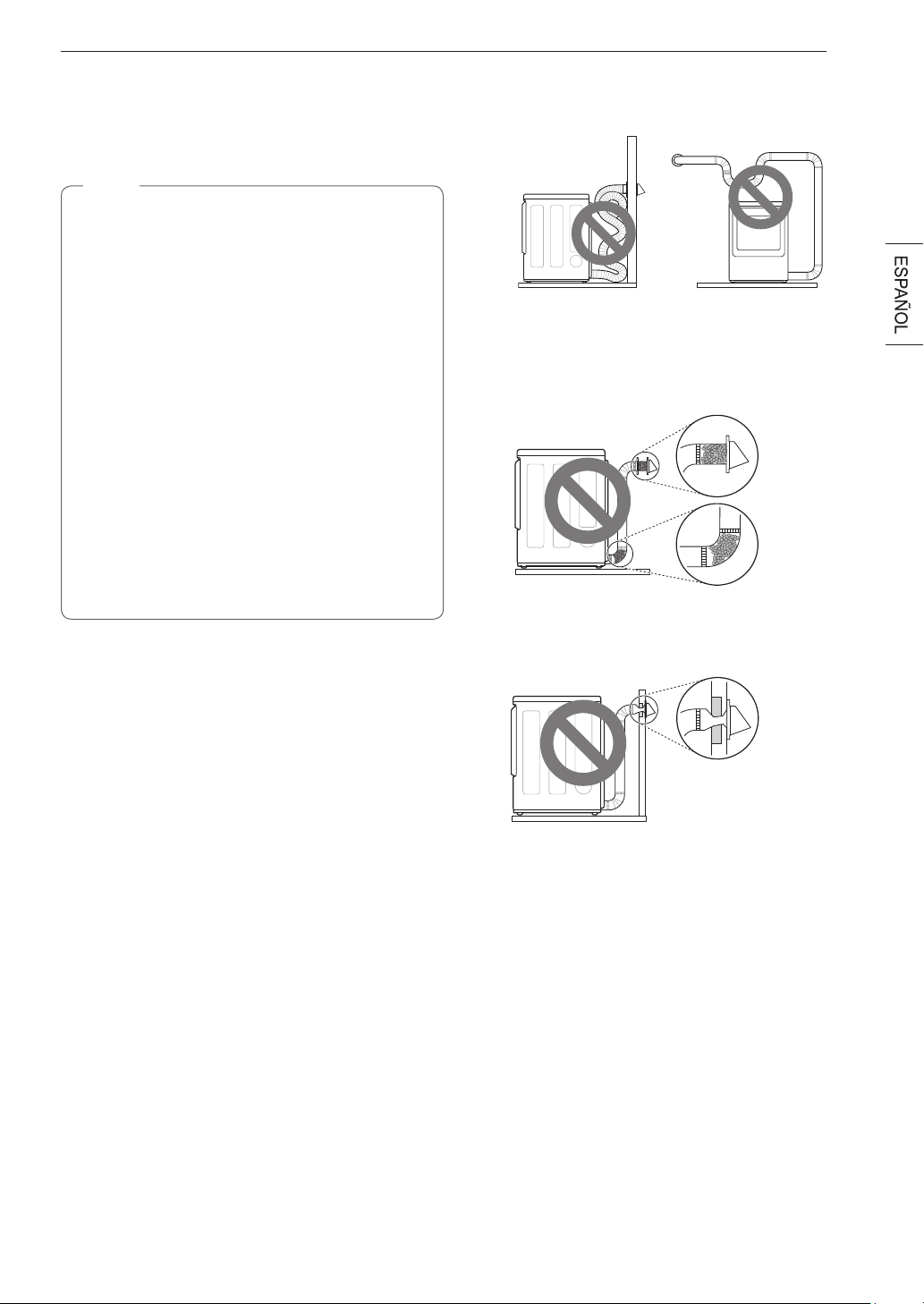
33INSTALACIÓN
•
Verifiquelascondicionesdelconducto
Si el LED de Flow Sense
TM
está encendido, revise el
sistema de escape para verificar que no haya restricciones
ni daños. Repare o reemplace el sistema de escape según
sea necesario.
NOTA
Cuando recién se instale la secadora, debe realizarse esta
prueba para que esté informado acerca de la presencia de
cualquier problema relacionado con el conducto de escape
de su casa. Sin embargo, puesto que la prueba realizada
durante un funcionamiento normal ofrece información más
precisa sobre el estado del conducto de escape que la
prueba de instalación, la cantidad de barras visualizadas
durante las dos pruebas puede no ser la misma.
No interrumpa el ciclo de prueba, ya que si lo hace, la
prueba puede arrojar resultados inexactos.
Aunque no se haya visualizado ninguna barra durante
el ciclo de prueba, aún puede haber restricciones en el
sistema de escape. Consulte la sección Ventilación de la
secadora de este manual para obtener detalles sobre el
sistema de escape y los requisitos de ventilación.
Su secadora cuenta con Flow Sense™, un sistema
innovador que detecta automáticamente los bloqueos
y las restricciones en los conductos de la secadora.
Mantener los conductos sin acumulación de pelusa y
sin restricciones le permitirá secar la ropa más rápido y
reducir el uso de energía.
Flujodeairerestringidoobloqueado
Evite tendidos largos o con muchos codos o curvas.
Conducto de transición
muy largo o apretado
Demasiado largo o con
demasiados codos
Compruebe la presencia de bloqueos y acumulación de
pelusa.
Acumulación
de pelusa o
bloqueo
Asegúrese de que los conductos no estén aplastados ni
restringidos.
Conducto
de escape
aplastado o
dañado
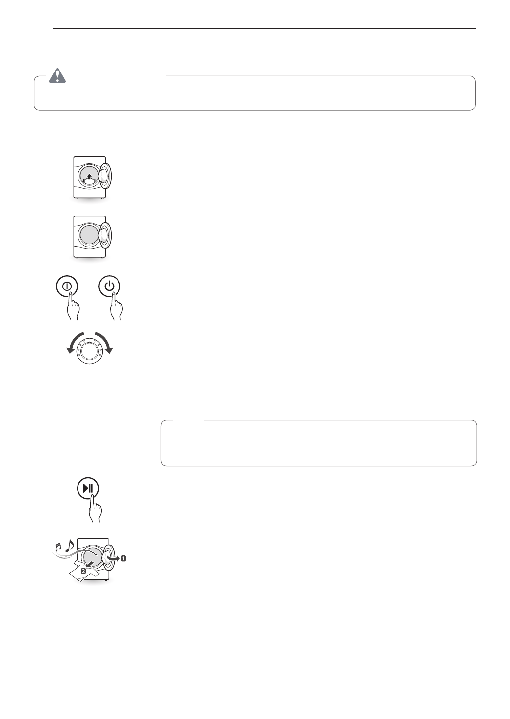
34 FUNCIONAMIENTO
FUNCIONAMIENTO
ADVERTENCIA
Para reducir el riesgo de incendio, descargas eléctricas o lesiones personales, lea este manual por completo, incluso
las INSTRUCCIONES IMPORTANTES DE SEGURIDAD, antes de operar esta secadora.
Cómo usar la secadora
1 Limpie el filtro de pelusa
Si el filtro de pelusa no se ha limpiado aún, extráigalo y elimine las pelusas de la última carga.
Esto le ayudará a asegurar un rendimiento de secado más rápido y eficiente. Asegúrese de
volver a instalar el filtro, colocándolo en su lugar y presionando hacia abajo hasta que haga
clic. La secadora no funcionará si el filtro de pelusa no está en su lugar.
2 Cargue la secadora
Cargue en la secadora la carga húmeda de la lavadora. Si la carga es muy grande, es posible
que deba dividirla en cargas más pequeñas para obtener un buen rendimiento y cuidar los
tejidos.
3 Encienda la secadora
Presione el botón POWER para ENCENDER la secadora. Las luces LED de los ciclos se
encenderán y se emitirá un sonido.
4 Seleccione un ciclo
Gire el mando del selector de ciclo en cualquier sentido hasta que se ilumine el LED del
ciclo que desee. Se mostrarán los ajustes preestablecidos de temperatura, nivel de secado y
opción para este ciclo. Consulte la página 37.
Los ajustes predeterminados para el ciclo seleccionado podrán cambiarse ahora si lo desea.
Esto puede llevarse a cabo utilizando los botones modificadores de ciclo tal y como se
muestra en la página 37. Las opciones de ciclo pueden añadirse utilizando los botones de
opción tal y como se muestra en la página 38-41.
NOTA
No todas las opciones ni modificadores están disponibles para todos los ciclos. Se
escuchará un sonido diferente y la luz LED no se iluminará si la selección no está
permitida.
5 Inicie el ciclo
Presione el botón
START/PAUSE
para iniciar el ciclo. El ciclo puede pausarse en cualquier
momento abriendo la puerta o presionando el botón
START/PAUSE
. Si el ciclo no vuelve a
iniciarse tras 4 minutos, la secadora se apagará y los ajustes se perderán.
Lint
Filter
6 Fin del ciclo
Al finalizar el ciclo, se emitirá un sonido. Retire inmediatamente sus prendas de la secadora
para reducir las arrugas. Si tiene seleccionada la función Prevención de arrugas, la secadora
hará un breve centrifugado cada pocos minutos para ayudar a prevenir la formación de
arrugas en sus prendas.
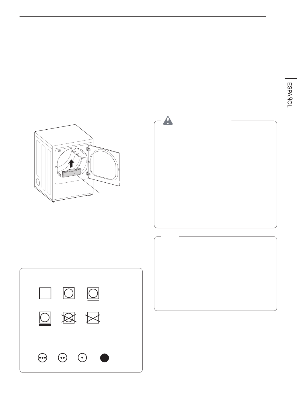
35FUNCIONAMIENTO
Revise el filtro de pelusa antes
de cada carga
Asegúrese siempre de que el filtro de pelusa esté limpio antes
de iniciar una carga nueva; un filtro de pelusa bloqueado
incrementará los tiempos de secado. Para limpiarlo, tire del
filtro de pelusa hacia arriba y, con los dedos, haga rodar las
pelusas para retirarlas del filtro. No enjuague ni lave el filtro
para eliminar las pelusas. Empuje el filtro de pelusa firmemente
para colocarlo en su lugar. Consulte la sección
Limpieza
regular
para obtener más información.
Asegúrese siempre de que el filtro de pelusa esté instalado
correctamente antes de poner en funcionamiento la secadora.
Hacer funcionar la secadora sin el filtro o con el filtro de pelusa
suelto podría dañar la secadora y las prendas en su interior.
Filtro de pelusa
Clasificación de cargas
Etiquetasdecuidadodelostejidos
La mayoría de las prendas contienen etiquetas de cuidado
de los tejidos que incluyen instrucciones para un cuidado
adecuado.
Etiquetasdecuidadodelostejidos
Ajuste de calor
Alto
Medio Bajo
Sin calor/aire
Secado por centrifugado
Seco
Normal
Planchado permanente/
antiarrugas
Suave/
delicado
No secar por
centrifugado
No secar
(utilizado junto a "no lavar")
Agrupe prendas similares
Para lograr mejores resultados, clasifique las prendas en
cargas que puedan secarse con el mismo ciclo de secado.
Los diferentes tipos de tejidos tienen diferentes requisitos de
cuidado y algunos tejidos se secarán más rápido que otros.
Para lograr los mejores resultados de cuidado de tejidos,
siempre agrupe los tejidos que tengan los mismos requisitos
de cuidado.
Carga de la secadora
ADVERTENCIA
Para reducir el riesgo de incendio, descargas
eléctricasolesionespersonalesalusaresteequipo,
siga las precauciones básicas, incluso lo siguiente:
•
Revisetodoslosbolsillosparaasegurarsedeque
estén vacíos. Los artículos como clips, bolígrafos,
monedas y llaves pueden dañar su secadora y su
ropa. Los objetos inflamables, como encendedores
o fósforos podrían encenderse y provocar un
incendio. Si esto no se cumple, se podrá producir una
explosión, un incendio o la muerte.
•
Nuncasequeprendasquehayansidoexpuestas
a aceite, gasolina u otras sustancias inflamables.
Lavar las prendas no eliminará completamente los
residuos de aceite. Si no se obedece esta advertencia,
se puede producir un incendio, una explosión o la
muerte.
NOTA
Consejos para la carga
•
Combine prendas grandes y pequeñas en una misma
carga.
•
Las prendas húmedas se expandirán cuando se sequen.
No sobrecargue la secadora; las prendas necesitan de
espacio para girar y secarse adecuadamente.
•
Use bolsas de malla para lavandería para separar las
prendas con cremalleras, ganchos, tirantes y cuerdas
para evitar que se enganchen o enreden con otras
prendas o dañen el filtro de pelusa.
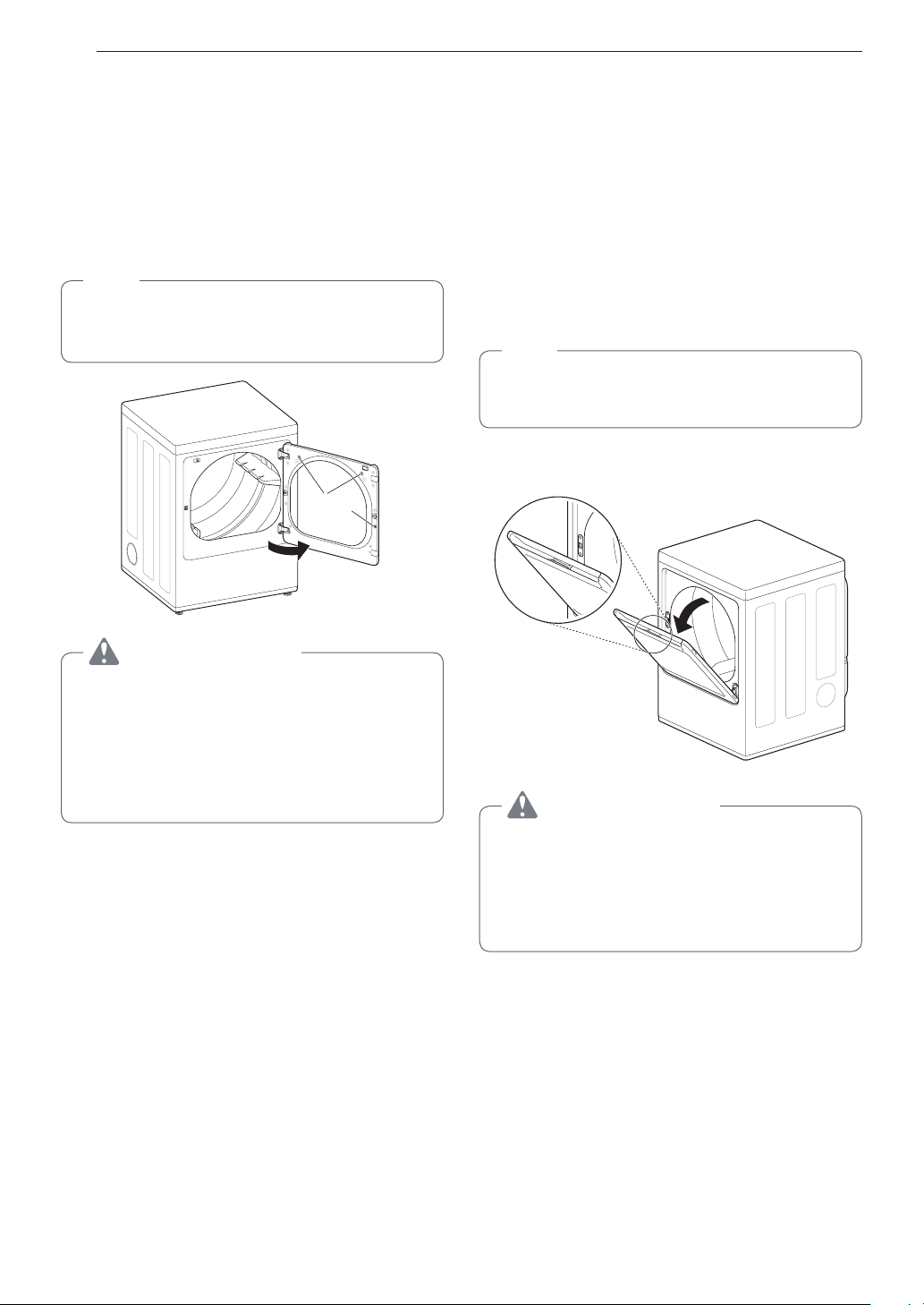
36 FUNCIONAMIENTO
Uso de la función LG
EasyLoad
TM
Puerta abatible
Utilice la puerta abatible para cargar o descargar prendas más
voluminosas y así para tener un fácil acceso al tambor.
Para abrir la puerta abatible, tome la parte superior de la
puerta del lado contrario a las bisagras y tire.
NOTA
Asegúrese de que el dispositivo de abertura de la puerta
de apertura superior esté completamente cerrado antes
de usar la puerta abatible.
Puerta abatible
Botones de
bloqueo
ADVERTENCIA
No presione los tres botones de bloqueo cuando la puerta
esté abierta. La puerta podría caerse y ocasionar lesiones
graves.
•
Nocoloqueobjetospesadosniseapoyecontrala
parte superior de la puerta cuando esta esté abierta.
La secadora podría volcarse hacia adelante y ocasionar
lesiones o daños a la propiedad.
Puerta de apertura superior
(en algunos modelos)
La puerta de tipo cesto se abre de aproximadamente 40 grados
y actúa como un conducto para ayudarle a colocar la ropa en
el tambor y evitar que las prendas caigan al suelo. También es
práctica para la descarga de pocas prendas pequeñas, ya que
ayuda a evitar que las demás prendas caigan al suelo.
Para abrir la puerta de apertura superior, presione el dispositivo
de abertura que se encuentra en la parte superior de la puerta
y tire la puerta hacia adelante.
Asegúrese de que las prendas estén dentro del tambor antes
de cerrar la puerta.
NOTA
Asegúrese de que la cerradura de la puerta abatible esté
completamente cerrada antes de presionar el dispositivo
de abertura de la puerta de apertura superior.
Dispositivo de
abertura de la puerta
de abertura superior
Puerta de apertura superior
40°
ADVERTENCIA
•
No intente abrir la puerta de apertura superior en un
ángulo superior a 40 grados.
•
Tenga cuidado al abrir y cerrar la puerta. Los dedos
y las manos pueden quedar atrapados en la puerta y
se pueden producir lesiones si la puerta se cae hacia
adelante de manera inesperada.
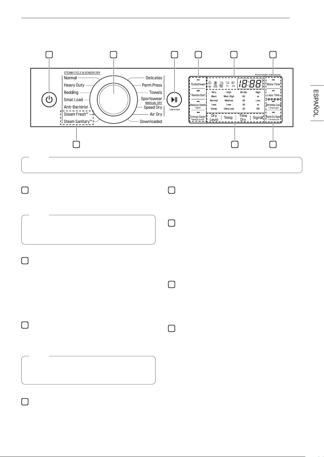
37FUNCIONAMIENTO
Panel de control
1 2 3 5 64
8 47
NOTA
Los números de los modelos se encuentran en el gabinete, dentro de la puerta.
1
BotónPOWER(Encendido)
Presione para ENCENDER la secadora. Presione nuevamente
para APAGAR la secadora.
NOTA
Si presiona el botón POWER durante un ciclo, se
cancelará dicho ciclo y los ajustes de la carga se
perderán.
2
Perilla Selecto Ra De Cicios
Gire esta perilla para seleccionar el ciclo deseado. Una vez
que se haya seleccionado el ciclo deseado, los preajustes
estándar se mostrarán en la pantalla. En los ciclos de Secado
Manual (Manual Dry) se pueden programar estos ajustes
usando los botones de ajuste de ciclos en cualquier momento
antes de iniciar el ciclo.
3
Botón START/PAUSE (Inicio/Pausa)
Presione este botón para iniciar el ciclo seleccionado. Si la
secadora está funcionando, use este botón para pausar el ciclo
sin perder los ajustes actuales.
NOTA
Si no presiona el botón START/PAUSE para reanudar un
ciclo tras 60 minutos, la secadora se apagará de forma
automática.
4
Botones de opciones de ciclo
Los botones de opciones le permiten seleccionar opciones de
ciclo adicionales. Algunos botones también le permiten activar
funciones especiales si se los mantiene presionados durante
3 segundos.
5
Pantalladevisualizacióndetiempoyestado
La pantalla muestra los ajustes, el tiempo restante estimado,
las opciones y los mensajes de estado de su secadora.
6
Botones MORE TIME/LESS TIME (Más tiempo/Menos
tiempo)
Use estos botones con los ciclos Time Dry y MANUAL DRY
para ajustar el tiempo de secado. Presione el botón
More
Time
para aumentar el tiempo del ciclo manual seleccionado
en intervalos de 5 minutos; presione el botón
Less Time
para
disminuir el tiempo del ciclo en intervalos de 5 minutos.
7
Botones de modificación de ciclo
Use estos botones para seleccionar los ajustes de ciclo
deseados para el ciclo seleccionado. Los ajustes actuales se
muestran en la pantalla. Presione el botón de la opción para
seleccionar otros ajustes.
8
Funciones de vapor
La tecnología de vapor de LG permite inyectar un chorro de
vapor en forma de remolino en los tejidos para refrescar la
ropa, reducir la estática y facilitar el planchado. Simplemente,
seleccione el ciclo
SteamFresh™
o añada una opción de
vapor a los ciclos seleccionados.
38 FUNCIONAMIENTO
9 1210 11
1314
9
IndicadordeBloqueoInfantil
Cuando se ha establecido Control Lock(
BloqueoInfantil
),
el indicador Control Lock(
BloqueoInfantil
) aparece y
todos los botones son deshabilitados a excepción del botón
Power(Encendido)
. Esto previene que los niños cambien la
configuración mientras la segadora está en operación.
10
Indicadordelsistemadedeteccióndebloqueodel
conductoFlowSense™
El sistema de detección de bloqueo del conducto Flow
Sense™ detecta y alerta en el caso de que haya bloqueos en
los conductos domésticos que reduzca el flujo de escape de
la secadora. El mantenimiento de un sistema de escape limpio
mejora la eficacia de funcionamiento y ayuda a minimizar las
llamadas al servicio técnico, lo que le permite ahorrar dinero.
11
Recordatoriodelimpiezadefiltro
La pantalla indicará Clean Filter (Limpiar filtro) cuando la
secadora está encendida como recordatorio para revisar el
filtro. Se apaga cuando se presiona el botón
START/PAUSE
.
12
Indicador de Completado de Ciclo
Esta parte de la pantalla muestra la etapa del ciclo de secado
que se está llevando a cabo actualmente (Secado, Enfriado).
13
Tiempo restante estimado
Esta pantalla muestra el tiempo restante estimado de los ciclos
SENSOR DRY o el tiempo restante efectivo de los ciclos Time
Dry o MANUAL DRY.
NOTA
El tiempo del ciclo en los ciclos SENSOR DRY puede
variar, ya que la secadora vuelve a calcular el tiempo de
secado para obtener óptimos resultados.
14
IndicadordeWi-Fi
Cuando el electrodomestico este conectado a Internet a traves
de la red Wi-Fi de su hogar, aparecera este indicador.
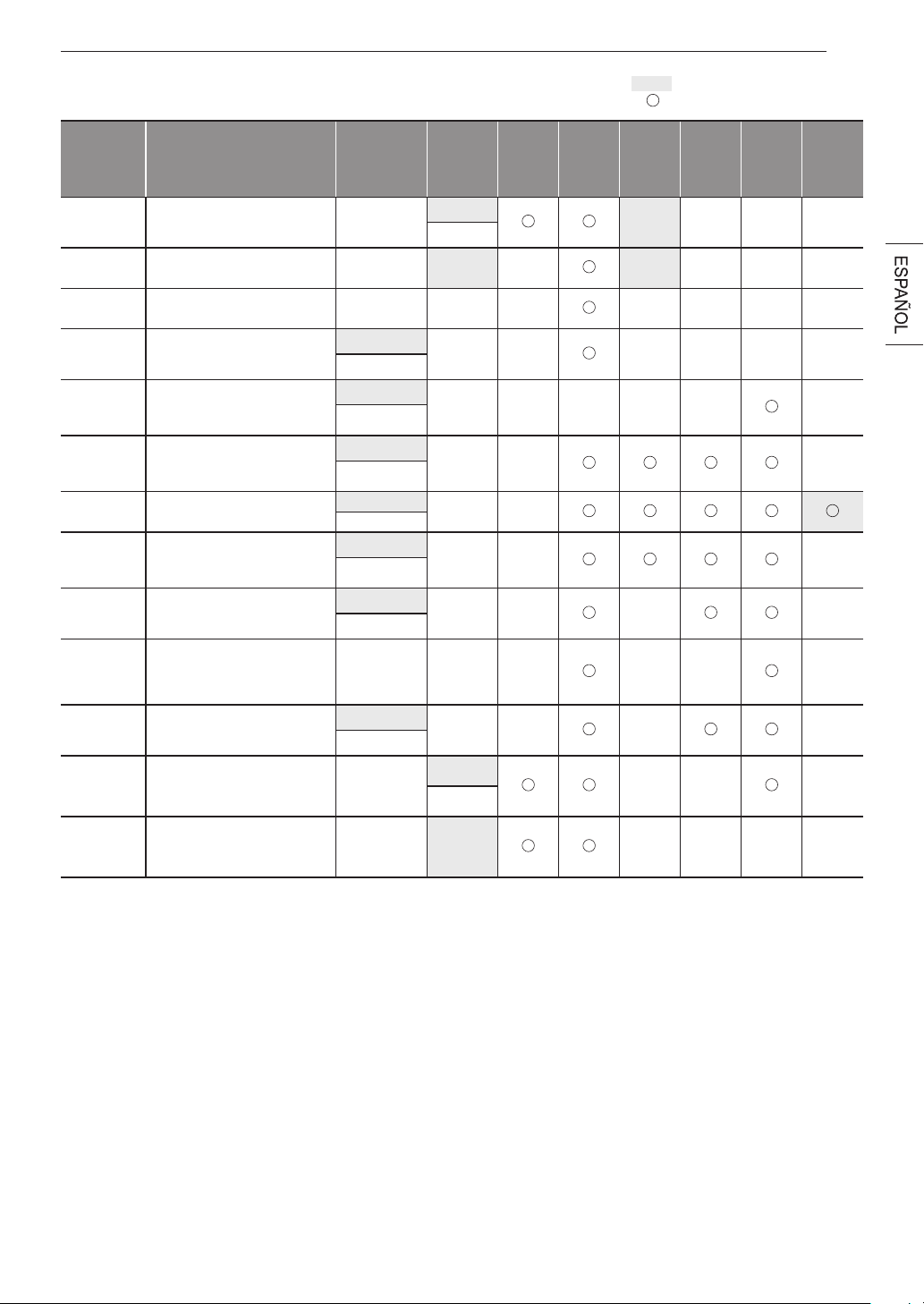
39FUNCIONAMIENTO
Guía de ciclos
Ciclo Tipo de tela
Nivel de
secado
Temperatura
Más
tiempo/
Menos
tiempo
Cuidado
de
arrugas
Turbo
Steam
Sonido
de
secado
húmedo
Reduc-
ción
estática
El
ahorro
de
energía
Steam
Fresh
TM
Acolchados, camisas,
pantalones (excepto prendas
muy delicadas)
Apagado
Medio Alta
Regulable
Steam
Sanitary
TM
Acolchados, ropa de cama,
ropa de niños.
Apagado Alta
Anti
Bacterial
No utilizar este ciclo con
prendas delicadas.
Muy Seco Alta
Poca Carga
(Small Load)
Sólo prendas normales y de
algodón/tipo toallas (máx.
aprox. 1,5 kg)
Normal seco
Alta
Regulable
Ropa de
cama
(Bedding)
Acolchados, almohadas,
camisas.
Normal seco
Media
Regulable
Secado
Intenso
(Heavy Duty)
Vaqueros, prendas pesadas.
Normal seco
Alta
Regulable
Normal
(Normal)
Ropa de trabajo, pana, etc.
Normal seco
Medio Alta
Regulable
Planchado
Perm.
(Perm. Press)
Prendas sintéticas, planchado
permanente.
Normal seco
Media
Regulable
Toallas
(Towels)
Prendas vaqueras, toallas,
algodón resistente.
Normal seco
Medio Alta
Regulable
Ropa de-
Portiva
(Sportswear)
Ropa deportiva Apagado -
Delicado
(Delicates)
Lencería, sábanas, blusas
Normal seco
Baja
Regulable
Secado
Rápido
(Speed Dry)
Para poca carga con tiempos
de secado cortos.
Apagado
Alta
Regulable
Secado Por
Aire
(Air Dry)
Para prendas que no precisan
calor, por llevar plástico o
goma
Apagado Sin Calor
= configuración por defecto
= opción permisible de

40 FUNCIONAMIENTO
Ciclos de secado con sensor (sensor dry)
Los ciclos de secado con sensor utilizan el sistema exclusivo
de sensor doble de LG para detectar y comparar el nivel de
humedad en las prendas y en el aire, y programar el tiempo
de secado del modo necesario para asegurar resultados
superiores. La secadora ajusta automáticamente el nivel de
sequedad y temperatura del ajuste recomendado para cada
ciclo. El tiempo restante estimado se mostrará en la pantalla.
NOTA
Para proteger sus prendas, no todos los niveles,
temperatura u opciones están disponible con cada ciclo.
Consulte la guía de ciclos para los detalles.
Ciclos de secado manual (manual dry)
Use los ciclos de secado manual para seleccionar una
cantidad especifica de tiempo y temperatura de secado.
Cuando se selecciona el ciclo de secado manual, la pantalla
de Tiempo Restane Estimado (Estimated Time Remaining)
muestra el tiempo restante real en su ciclo. Puede cambiar el
tiempo real en el ciclo apretando Más Tiempo (More Time) o
Menos Tiempo (Less Time).

41FUNCIONAMIENTO
Ajustes y opciones de ciclo
Botonesdemodicacióndeciclo
Los ciclos SENSOR DRY tienen ajustes predefinidos que
se seleccionan de manera automática. Los ciclos MANUAL
DRY tienen ajustes predeterminados, pero también pueden
personalizarse a través de los botones de modificación de
ciclo. Presione el botón de la opción deseada para visualizar y
seleccionar otros ajustes.
Dry Level
Selecciona el nivel de sequedad para el ciclo. Presione el
botón
Dry Level
repetidas veces para deslizarse por los
ajustes disponibles.
•
Esta opción solo está disponible con los ciclos SENSOR
DRY.
•
La secadora ajustará el tiempo del ciclo de forma
automática. Si se selecciona More or Very aumentará el
tiempo del ciclo, mientras que Less or Damp disminuirá el
tiempo del ciclo.
•
Use un ajuste Less Dry o Damp Dry para las prendas que
desee planchar.
Temp.
Regula el ajuste de temperatura. Esto permite el cuidado
preciso de sus tejidos y prendas. Presione el botón
Temp.
repetidas veces para deslizarse por los ajustes disponibles.
Time Dry
Permite seleccionar el tiempo de secado de forma manual,
de 20 a 60 minutos, en incrementos de 10 minutos. Use esta
opción para cargas pequeñas o para eliminar arrugas.
Signal
Presione el botón
Signal
repetidas veces para modificar el
volumen o para encender o apagar los tonos de los botones y
la melodía de fin de ciclo.
Botones de opciones de ciclo
Su secadora cuenta con varias opciones de ciclo adicionales
para personalizar los ciclos y satisfacer sus necesidades
individuales. Algunos botones de opciones también incorporan
una función especial (ver la siguiente página para obtener más
detalles) que puede activarse al mantener presionado el botón
de dicha opción durante 3 segundos.
Para añadir opciones de ciclo a un ciclo determinado
1
Encienda la secadora y gire la perilla de selección de
ciclo para seleccionar el ciclo deseado.
2
Use los botones modificadores de ciclo para configurar
los ajustes para ese ciclo.
3
Presione los botones de opción de ciclo para agregar
las opciones deseadas. Aparecerá un mensaje de
confirmación en la pantalla.
4
Presione el botón de
Start/Pause(Inicio/Pausa)
para
iniciar el ciclo. La secadora se inicia de forma automática.
WrinkleCare
Al seleccionar esta opción, la secadora hará un centrifugado
periódico por un período de hasta 3 horas después del ciclo
seleccionado o hasta que se abra la puerta. Esto ayuda a
prevenir la formación de arrugas cuando no le sea posible
retirar las prendas de la secadora inmediatamente.
Damp Dry Signal
Con esta opción, la secadora le indicará cuando la carga esté
aproximadamente 80 % seca. Esta función le permite retirar
las prendas livianas que se secan más rápidamente o las que
desee planchar o colgar mientras aún se encuentren húmedas.
Energy Saver (sur certains modèles)
Esta opción ayuda a reducir el consumo de energía en el ciclo
Normal según el tamaño de la carga.
Cuando se seleccione el ahorro de energia, el ciclo comienza
con una seccion de secado por aire y se aumenta el tiempo de
secado.
NOTA
La opción Energy Saver se activa de forma
predeterminada en el ciclo Normal. Puede desactivar la
opcion de ahorro de energia para un ciclo Normal mas
rapido que comienza con secado caliente.

42 FUNCIONAMIENTO
Funciones especiales
Algunos botones de opciones de ciclo también activan
funciones secundarias. Estas funciones especiales están
indicadas con un asterisco (*). Mantenga presionado el botón
de opción que indica la función especial para activarla.
*DRUMLIGHT(ILUMINACIÓNDELTAMBOR)
El tambor está equipado con una luz LED azul que se
ilumina cuando la secador es encendida. La luz de apaga
automáticamente cuando la puerta se cierra y el ciclo inicia.
Para encender la luz durante el ciclo, presione y mantenga
sostenido el botón de Wrinkle Care durante tres segundos.
La luz del tambor se iluminará y luego se apagará
automáticamente después de cuatro minutos.
* Control Lock
Use esta opción para evitar un uso no deseado de la secadora
o para evitar modificaciones en los ajustes de ciclo mientras la
secadora está en funcionamiento.
Mantenga presionado el botón con la indicación
Control Lock
durante 3 segundos para activar o desactivar la función Control
Lock. Se mostrará el icono Control Lock en la pantalla y se
desactivarán todos los controles, excepto el botón
POWER
.
NOTA
Una vez que se fija, la función Control Lock permanece
activa hasta que se desactive de forma manual. Se
debe desactivar la función Control Lock para ejecutar
otro ciclo.
Para desactivar Control Lock, mantenga
presionado el botón
Control Lock
durante 3 segundos.
* Activado/Desactivado por defecto (Default On/Off)
Esta opción permite la configuración de Ahorro de Energía
para ser cambiados.
Para ejecutar un ciclo Normal y sin la opción de Ahorro de
Energía, mantengapresionado durante tres segundos el botón
de Ahorro de Energía.
En la pantalla aparece Activado o Desactivado.
43FUNCIONAMIENTO
Funciones de vapor
La nueva tecnologia de vapor de LG le permite inyectar las
telas con un chorro giratorio de vapor caliente para refrescar
las prendas, reducir la estatica. Simplemente seleccione el
ciclo Steam Fresh™ o Steam Sanitary™. o agregue la opción
vapor a los ciclos seleccionados.
CómousarelcicloSteamFresh™
Steam Fresh™ utiliza solo el poder del vapor para rápidamente
reducir arrugas y olores de las telas. Da nueva vida a las
prendas arrugadas que han estado guardadas por mucho
tiempo Steam Fresh™ También puede usarse para reducir los
olores y remover los pliegues de las perchas en las prendas.
NOTA
•
Dependiendo del tamaño de la carga, puede
modificar el tiempo del ciclo presionando los botones
More Time (Más Tiempo) o Less Time (Menos
Tiempo). La pantalla muestra 1, 3, 5, o
.
Seleccione 3 para tres o menos prendas; seleccione
5 para cuatro o cinco prendas; y seleccione
para una carga grande, una prenda voluminosa
como ser una frazada, o para remover los pliegues
de las perchas.
ParausarelcicloSteamFresh™:
1
Encienda la secadora y gire la perilla selectora al ciclo
SteamFresh™
.
2
Para agregar una funcion opcional, seleccione Cuidado
De Arrugas (Wrinkle Care).
3
Dependiendo de la carga (cantidad de prendas), puede
modificarse el tiempo de vapor presionando los botones
Más Tiempo (More Time) o Menos Tiempo (Less Time)
4
Presione el botón de Inicio/Pausa (Start/Pause) para
iniciar el ciclo.
CómousarelcicloSteamSanitary™
El nuevo ciclo Steam Sanitary™ es idóneo para la
higienización rápida y sencilla de elementos que no pueden
lavarse, utilizando sólo el poder del vapor.
Recomendamos utilizar este ciclo para tejidos de algodón y
poliéster. (NO use para espuma de uretano, plumas o prendas
delicadas).
Cómo usar las opciónes de vapór
La opcíon Reducción Estática (Reduce Static) nyecta vapor
al final del ciclo de secado para reducir la electricidad estatica
producida por la friccion de telas. Modifique el tiempo del
ciclo presionando el botón Más Tiempo (More Time) o Menos
Tiempo (Less Time). La pantalla muestra la cantidad de
prendas recomendadas, por ejemplo, 7, 9, 11, 14, 16 ó 18.
TurboSteam ayuda a prevenir el sobresecado de la ropa
inyectando vapor durante el proceso de secado.
NOTA
•
Cuando se selecciona Secado Con Sensor (Sensor
Dry) con la opcíon Reducción Estática (Reduce
Static) o Turbo Steam. no puede seleccionarse Nivel
De Secado (Dry Level) de Menos (Less) o Humedo
(Damp).
•
Las opciones Reducción Estática (Reduce Static)
también pueden seleccionarse durante los ciclos
Tiempo De Secado(Time Dry).
•
Después de seleccionar la opción Vapor en Time
Dry, los botones Más Tiempo (More Time) o Menos
Tiempo (Less Time) TIME cambiarán el tiempo de
vapor ÚNICAMENTE.
•
Despues de presionar IInicio/Pausa (Start/Pause),
los botones Más Tiempo (More Time) o Menos
Tiempo (Less Time) Time no funcionarán.
Para agregar vapor a un ciclo estándar:
1
Encienda la secadora y gire la perilla selectora al ciclo
deseado.
2
Utilice los botones de configuración de ciclo para ajustar
las configuraciones para ese ciclo.
3
Presione el botón vapor para la opción que le gustaria
agregar. Luego ajuste el tamaño de carga utilizando los
botones Más Tiempo (More Time) o Menos Tiempo (Less
Time).
4
Presione el botón de Inicio/Pausa (Start/Pause) para
iniciar el ciclo.
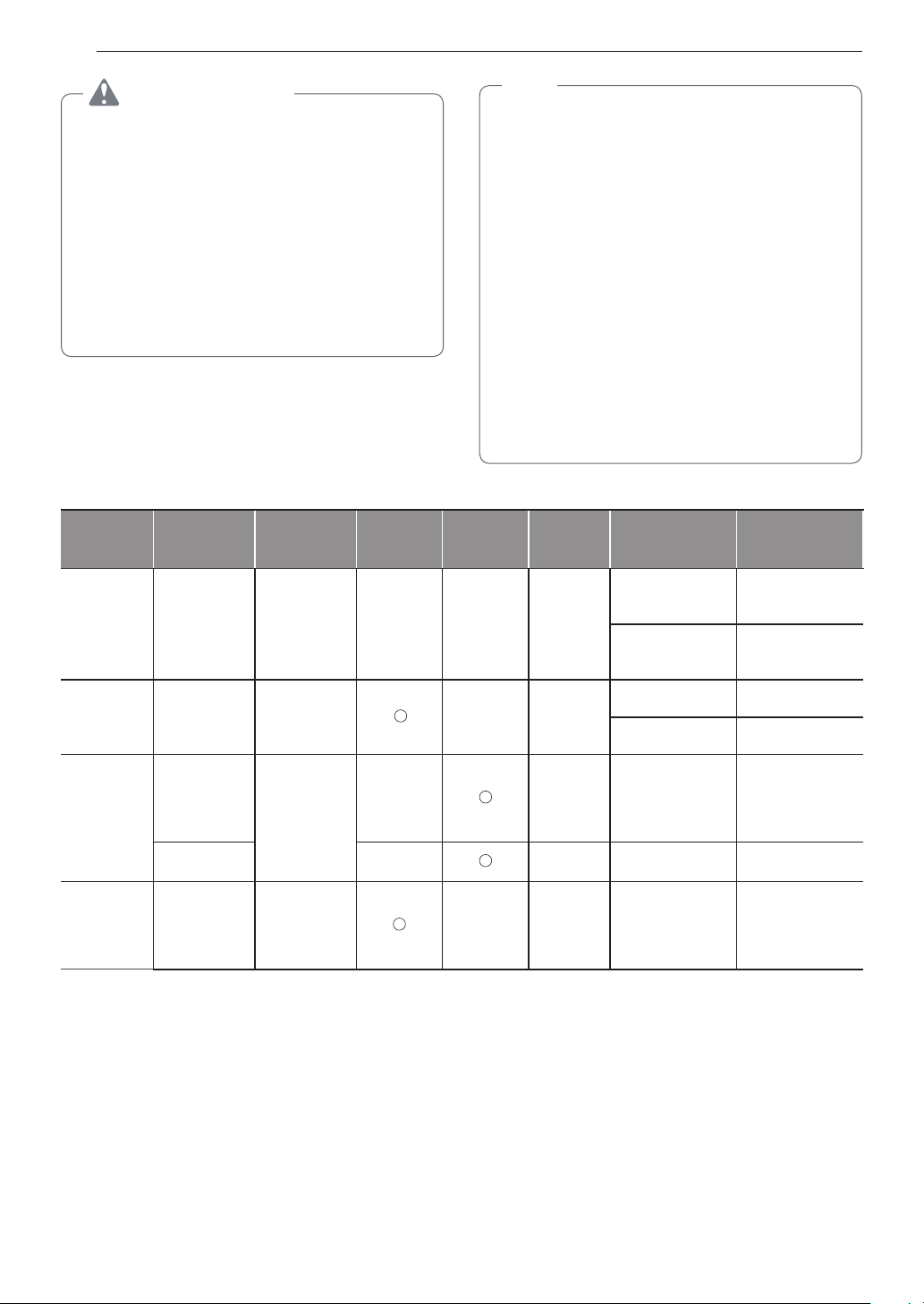
44 FUNCIONAMIENTO
ADVERTENCIA
•
No abra la puerta de la secadora durante ciclos de
vapor. Si no se cumple con esto se podrá producir una
explosión, incendio, quemaduras o muerte.
•
No llene el alimentador de vapor con gasolina,
solventesparalimpiezaenseco,uotrassustancias
inflamables o explosivas. Si no se cumple con esto se
podrá producir una explosión, incendio, quemaduras o
muerte.
•
Notoquelaboquilladevapordeltambordurante
o después del ciclo de vapor. Si no se cumple con
esta advertencia se podrán producir heridas graves o
muerte.
NOTA
•
Puede que el vapor no sea claramente visible
durante los ciclos de vapor. Esto es normal.
•
No use el ciclo Steam Fresh™ con elementos como
lana, manta de lana, camperas de cuero, seda, ropa
húmeda, lencería, productos de espuma o mantas
eléctricas.
•
Para mejores resultados, las prendas deben ser de
tamaños y de tipos de tela similares. No sobrecargue
la secadora.
•
Cuando se tapa el filtro/conducto, la opción vapor
puede no tener resultados óptimos.
•
Cuando la función vapor está siendo utilizada,
el tambor se detendrá para permitir que el vapor
permanezca en el tambor.
•
El alimentador de vapor debe llenarse con agua
hasta la línea MAX. De otro modo, se mostrará un
mensaje de Error.
Guía de ciclo de vapor
Vapor
Tiempo
programado
por la fábrica
Control
temp.
Nivel de
Secado
Estado de
tela
Tipo de tela Cantidad Máx.
Steam
Sanitary™
31 Min. Seca
Camisas, Ropa de
cama
Camisas (1 cada)
Ropa de niños 3 Ibs.
Steam
Fresh™
10 Min. Seca
Edredón Camisas (1 cada)
Camisas* 5 cada
Opción de
Vapor
+
Reducción
estática
(Reduce
Static)
Siga el ciclo
Seleccionado
Mojada
Varía según el ciclo
seleccionado
8 Ibs.
(18 ARTíCULOS)
+
Turbo Steam
Mojada
Varía según el ciclo
seleccionado
8 Ibs.
(18 ARTíCULOS)
Secado
Tempori-
zado
+
Reducción
estática
(Reduce
Static)
38 Min. Mojada
Varía según el ciclo
seleccionado
8 Ibs.
(18 ARTíCULOS)
*Camisa: mezcla de 70% algodón:30% poliéster. Excepto telas especialmente delicadas.
•
Cuando se tapan el filtro de pelusas o el conducto de salida, las opciones de vapor no darán los resultados adecuados.
•
Para mejores resultados, las prendas deben ser de tamaños y de tipos de tela similares. No sobrecargue la secadora.
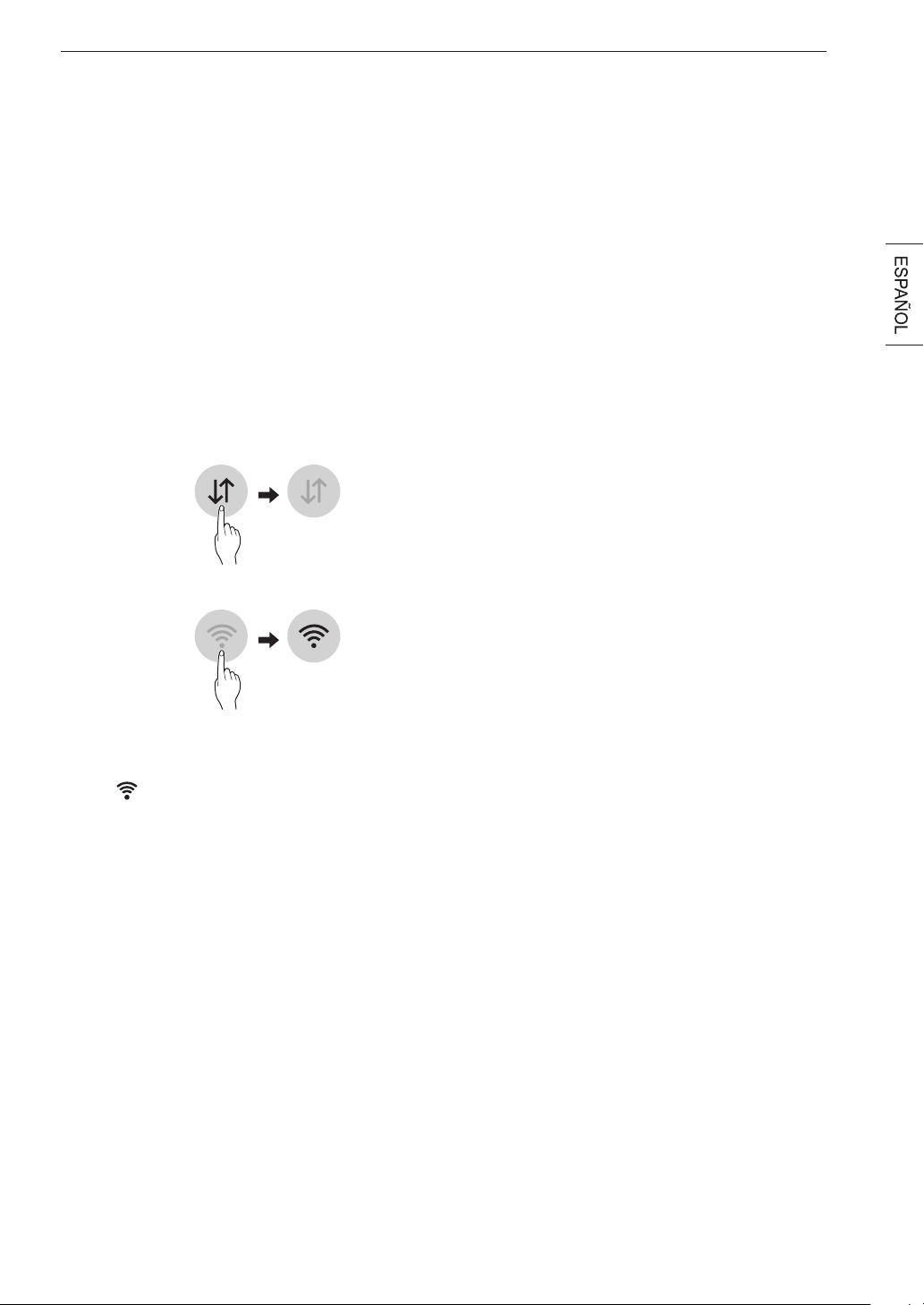
45FUNCIONES INTELIGENTES
FUNCIONES
INTELIGENTES
AplicaciónLGThinQ
La aplicación LG ThinQ le permite comunicarse con el
electrodoméstico usando un teléfono inteligente.
PrevioautilizarLGThinQ
1
Utilice un teléfono inteligente para verificar la
potencia del enrutador (Red Wi-Fi) cerca del
electrodoméstico.
•
Si la distancia entre el electrodoméstico y el enrutador
inalámbrico es muy grande, la señal será débil. Puede
que le tome más tiempo registrarse o que falle la
instalación.
2
Desactive los Datos Móviles o Datos Celulares
en su teléfono inteligente.
3
Conecte su teléfono inteligente al enrutador inalámbrico.
NOTA
• Para verificar la conexión Wi-Fi, revise que el ícono
Wi-Fi en el panel de control esté encendido.
• El electrodoméstico funciona únicamente con
redes Wi- Fi de 2,4 GHz. Contacte a su proveedor
de servicios de internet o verifique el manual del
enrutador inalámbrico para revisar la frecuencia de su
red.
• LG ThinQ no es responsable por ningún problema
de conexión en red, falla, mal funcionamiento o error
causado por la conexión de red.
• El entorno inalámbrico circundante puede hacer que el
servicio de red inalámbrica funcione lentamente.
• Si el aparato tiene problemas para conectarse a la red
Wi-Fi, es posible que se encuentre demasiado lejos
del router. Adquiera un repetidor Wi-Fi (extensor de
alcance) para mejorar la intensidad de la señal Wi-Fi.
• Es posible que la conexión de red no funcione bien por
cuestiones relacionadas con su proveedor de servicios
de Internet.
• Es posible que la conexión Wi-Fi no se conecte o se
interrumpa debido al entorno de la red doméstica.
• Si el electrodoméstico no puede registrarse debido a
problemas con la transmisión de la señal inalámbrica,
desconéctelo y espere alrededor de un minuto previo
a intentarlo de nuevo.
• Si el cortafuegos de su enrutador inalámbrico está
activado, desactivelo o añada una excepción a éste.
• El nombre de la red inalámbrica (SSID) debe ser
una combinación de letras y números. (No utilice
caracteres especiales)
• La interfaz de usuario (IU) del teléfono inteligente
puede variar dependiendo del sistema operativo (OS)
del móvil y del fabricante.
• Puede que la configuracióni de red falle si el protocolo
de seguridad del router está en WEP. Cambie el
protocolo de seguridad por otro (es recomendado el
WPA2) y registre el producto de nuevo.
InstalandolaAplicaciónLGThinQ
Busque la aplicación LG ThinQ en la tienda Google Play
Store o Apple App Store desde un teléfono inteligente.
Sigue las instrucciones para descargar e instalar la
aplicación.

46 FUNCIONES INTELIGENTES
Características de la Aplicación LG
ThinQ
Ciclo del secador
Descargue ciclos nuevos y especiales que no se
encuentran incluidos en los ciclos básicos del artefacto.
Los artefactos que se encuentran correctamente
registrados tienen la posibilidad de descargar una
variedad de ciclos especiales específicos para el
artefacto.
Solamente puede guardarse un ciclo por vez en el
artefacto.
Una vez que se completa la descarga de un ciclo en
el artefacto, el producto mantiene el ciclo descargado
hasta que se descarga un nuevo ciclo.
Avisodesensordeujo
Ofrece consejos de ventilación
SmartDiagnosis™
Esta función brinda información útil para diagnosticar
y resolver problemas con el producto conforme a su
patrón de uso.
Monitoreo de energía
El uso de energía del secador se ve afectado por los
ciclos y las opciones por lo que puede ver cambios en el
uso de energía dependiendo de los ciclos.
Enviar alertas
Tiene la opción de recibir notificaciones automáticas en
su teléfono inteligente cuando haya finalizado el ciclo o
cuando el artefacto presente problemas.
Conguración
Configure el apodo del producto y borre el producto.
NOTE
• Para verificar la conexión Wi-Fi, revise que el ícono
Wi-Fi en el panel de control esté encendido.
• LG ThinQ no es responsable por ningún problema
de conexión en red, falla, mal funcionamiento o error
causado por la conexión de red.
• La máquina solo admite redes Wi-Fi de 2,4 GHz.
• Si el aparato tiene problemas para conectarse a la red
Wi-Fi, es posible que se encuentre demasiado lejos
del router. Adquiera un repetidor Wi-Fi (extensor de
alcance) para mejorar la intensidad de la señal Wi-Fi.
• Es posible que la conexión Wi-Fi no se conecte o se
interrumpa debido al entorno de la red doméstica.
• Según el proveedor de servicios de Internet, la
conexión de la red puede no funcionar correctamente.
• El entorno inalámbrico circundante puede hacer que el
servicio de red inalámbrica funcione lentamente.
• Esta información está actualizada en el momento de
su publicación. La aplicación está sujeta a cambios
con fines de mejorar el producto sin previo aviso a los
usuarios.
Usando el Remote Start
(Inicio Remoto)
Utilice un teléfono inteligente para controlar el
electrodoméstico de forma remota o para revisar el
tiempo restante del ciclo.
1
Presione el botón de Power.
2
Carga del lavado.
3
Mantenga presionado el botón Remote Start por 3
segundos para habilitar la función Inicio Remoto.
4
Inicie un ciclo desde la aplicación LG ThinQ en su
teléfono inteligente.
NOTE
• Una vez se ha habilitado el Inicio Remoto, usted
puede empezar un ciclo desde la aplicación LG ThinQ
para teléfonos inteligentes. Si el ciclo no es iniciado,
la máquina esperará a que el ciclo se inicie hasta que
esta se apague de forma remota desde la aplicación, o
al deshabilitar el modo de Inicio Remoto.
• Si la puerta se abre, Inicio Remoto se deshabilitará.
Deshabilitando Inicio Remoto
Cuando el Inicio Remoto esté activado, mantenga
presionado el botón Remote Start por 3 segundos.

47FUNCIONES INTELIGENTES
Especificaciones módulo LAN inalámbrico
Rango de
frecuencia
2412 - 2462 MHz
Rango de
frecuencia (max.)
IEEE 802.11b: 22.44 dBm
IEEE 802.11g: 24.68 dBm
IEEE 802.11n: 24.11 dBm
Aviso de la FCC (para el módulo transmisor
contenido en este producto)
Este equipo fue probado y se determinó que cumple
con los límites para los dispositivos digitales de Clase
B, en conformidad con la parte 15 de las normas de la
FCC. Estos límites están diseñados para ofrecer una
protección razonable contra interferencias dañinas en
una instalación residencial. Este equipo genera, usa
y puede emitir energía de radiofrecuencia y, si no se
instala y utiliza de acuerdo con las instrucciones, podría
causar interferencias dañinas a las comunicaciones
por radio. Sin embargo, no se garantiza que dicha
interferencia no pueda ocurrir en instalaciones
particulares. Si este equipo causa interferencia dañina
a la recepción de radio o televisión, que se puede
determinar encendiendo y apagando el equipo, se
aconseja al usuario intentar corregir la interferencia
realizando alguna de las siguientes acciones:
• Reorientar o reubicar la antena receptora.
• Aumentar la separación entre el equipo y el receptor.
• Conectar el equipo a una toma de corriente en un
circuito diferente del utilizado por el receptor.
• Consultar al vendedor o a un técnico de radio/TV con
experiencia para solicitar ayuda.
Este dispositivo cumple con la parte 15 de las normas
de la FCC. La operación está sujeta a las dos siguientes
condiciones:
1) Este dispositivo no debe causar interferencia
dañina, y
2) Este dispositivo debe aceptar cualquier interferencia
recibida, incluso aquellas que pudieran causar un
funcionamiento no deseado del dispositivo.
Cualquier cambio o modificación en la construcción
de este dispositivo que no cuente con la aprobación
expresa de la parte responsable del cumplimiento,
puede anular la autorización del usuario para operar
este equipo.
Declaración sobre exposición a la radiación de
RF de la FCC
Este equipo cumple con los límites de exposición a
la radiación de la FCC establecidos para entornos
no controlados. Este transmisor no se debe ubicar ni
operar junto con ninguna otra antena ni transmisor.
El equipo se debe instalar y operar con una distancia
mínima de 20 cm (7,8 pulg.) entre la antena y su
cuerpo. Los usuarios deben seguir las instrucciones de
operación específicas de manera tal de cumplir con las
normas de exposición a la RF.
Información de anuncio de
programas de código abierto
Para obtener el código fuente bajo GPL, LGPL, MPL
y otras licencias de código abierto que contiene este
producto, visite http://opensource.lge.com. Además del
código fuente, se pueden descargar los términos de la
licencia, las anulaciones de la garantía y los avisos de
derechos de autor.
LG Electronics también le proporcionará el código
fuente abierto en un CD-ROM con un cargo que cubra
el costo de realizar tal distribución (como el costo de los
medios, el envío y el manejo) con una previa solicitud
por correo electrónico a opensource@lge. com. Esta
oferta es válida durante tres (3) años a partir de la fecha
de adquisición del producto.
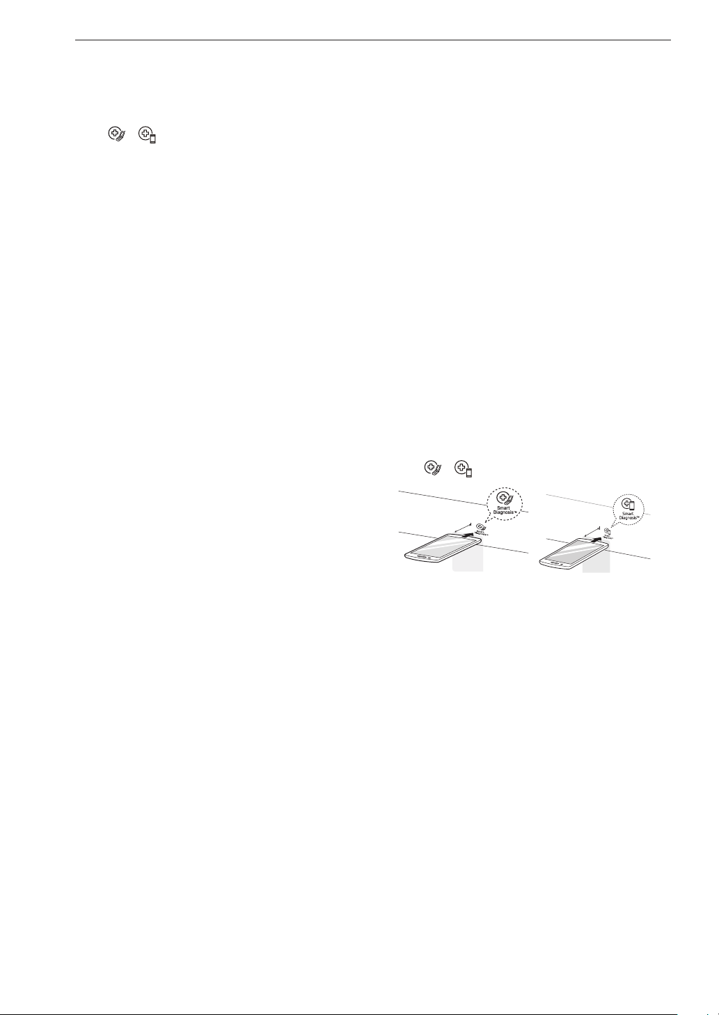
48 FUNCIONES INTELIGENTES
FunciónSmartDiagnosis™
(Diagnóstico Inteligente)
Esta característica solo está disponible en el modelo
con el logo o .
Utilice esta función como ayuda para diagnosticar y
resolver problemas con su electrodoméstico.
NOTA
• Por motivos no atribuibles a la negligencia de LGE, es
posible que el servicio no pueda funcionar debido a
factores externos como por ejemplo, la indisponibilidad
de Wi-Fi, desconexión de Wi-Fi, política de la
tienda de aplicaciones local o indisponibilidad de
aplicaciones, entre otros.
• Esta función puede estar sujeta a cambios sin previo
aviso y puede tener una forma diferente según dónde
se encuentre ubicado.
UsodeLGThinQparadiagnosticar
problemas
Si experimenta un problema con su electrodoméstico
equipado con Wi-Fi, este puede transmitir datos sobre
la resolución de problemas a un teléfono inteligente con
la aplicaciónLGThinQ.
• Inicie la aplicación LGThinQy seleccione la función
SmartDiagnosis™ en el menú. Siga las instrucciones
provistas en la aplicación LGThinQ.
Uso del diagnóstico audible para
diagnosticar problemas
Siga las instrucciones a continuación para utilizar el
método de diagnóstico audible.
• Inicie la aplicaciónLGThinQ y seleccione la función
SmartDiagnosis™ en el menú. Siga las instrucciones
para el diagnóstico audible provistas en la aplicación
LGThinQ.
1
Presione el botón Power para encender el
electrodoméstico.
• No presione ningún otro botón.
2
Mantenga el micrófono de su teléfono en frente del
logo o .
Max.
10 mm
Max.
10 mm
3
Mantenga presionado el botón Temp. durante 3
segundos o más mientras sigue manteniendo el
teléfono cerca del logo.
4
Mantenga el teléfono allí hasta que la transmisión
de tonos haya terminado. La pantalla contará
el tiempo hacia atrás. Una vez que la cuenta
regresiva haya terminado y se hayan detenido los
tonos, el diagnóstico se mostrará en la aplicación.
NOTA
• Para obtener resultados óptimos, no mueva el teléfono
mientras se transmitan los tonos.
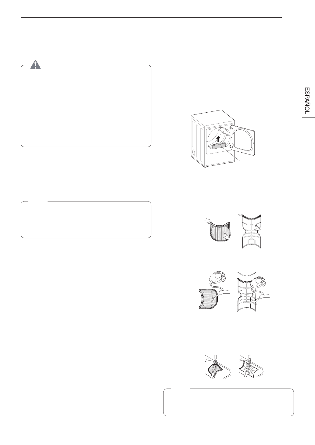
49MANTENIMIENTO
MANTENIMIENTO
Limpiezaregular
ADVERTENCIA
Para reducir el riesgo de incendio, descargas eléctricas
o lesiones personales al usar este equipo, siga las
precauciones básicas, incluso lo siguiente:
•
Desenchufelasecadoraantesdelalimpiezapara
evitar el riesgo de descargas eléctricas. Si no se
cumple con esta advertencia, se podrán producir
lesiones graves, incendios, descargas eléctricas o la
muerte.
•
Al limpiar la secadora, nunca utilice sustancias
químicasfuertes,limpiadoresabrasivosni
solventes. Dañarán su acabado.
Limpiezadelexterior
El mantenimiento adecuado de su secadora puede prolongar
su vida útil. La parte exterior de la máquina puede limpiarse
con agua tibia y un detergente para el hogar suave, no
abrasivo. Limpie inmediatamente cualquier derrame con un
paño suave y húmedo.
NOTA
•
No use alcohol metílico, solventes ni productos
similares.
•
Nunca use limpiadores abrasivos o de lana metálica;
pueden dañar la superficie.
Limpiezadelinterior
Limpie con un paño alrededor de la abertura y el sello de
la puerta con un paño suave y húmedo para prevenir la
acumulación de pelusa y polvo que podrían dañar el sello de la
puerta.
Limpie la ventana con un paño suave humedecido con agua
tibia y un detergente para el hogar suave, no abrasivo; luego,
seque con un paño.
Se puede limpiar el tambor de acero inoxidable con un
limpiador para acero inoxidable convencional según las
especificaciones del fabricante. Nunca use limpiadores
abrasivos ni de lana metálica; pueden rayar o dañar la
superficie.
Limpiezaalrededordelasecadoray
debajo de ella
Aspire la pelusa y el polvo alrededor de la secadora y debajo
de ella con regularidad. Se debe revisar que los conductos
de ventilación no tengan acumulación de pelusa y se deben
limpiar, al menos, una vez por año. Si se percibe una reducción
notoria del flujo de aire o del desempeño de secado, revise los
conductos de inmediato para verificar que no estén bloqueados
ni tengan obstrucciones.
Mantenimiento de los conductos
Se deben revisar los conductos de ventilación para verificar
que no tengan acumulación de pelusa una vez por mes y se
deben limpiar, al menos, una vez por año. Si se percibe una
reducción notoria del flujo de aire o del desempeño de secado,
revise los conductos de inmediato para verificar que no estén
bloqueados ni tengan obstrucciones. Llame a un técnico
calificado o a un proveedor de servicios de mantenimiento.
Limpiezadelltrodepelusa
Limpie siempre el filtro de pelusa después de cada ciclo.
Filtro de pelusa
Para limpiarlo, abra la puerta de la secadora y tire del filtro de
pelusa hacia arriba. Luego:
1
En el caso de una limpieza diaria, con los dedos, haga
rodar las pelusas para retirarlas del filtro.
2
Aspire el filtro de pelusa.
3
Si el filtro de pelusa se ha ensuciado mucho o se ha
obstruido con suavizante de ropa, lávelo en agua tibia
jabonosa y déjelo secar completamente antes de volverlo
a colocar.
NOTA
NUNCA haga funcionar la secadora sin haber colocado
antes el filtro de pelusa. NUNCA haga funcionar la
secadora con un filtro de pelusa húmedo.

50 SOLUCIÓN DE PROBLEMAS
SOLUCIÓN DE PROBLEMAS
Preguntas frecuentes
P: Cuandopresionounbotón,¿porquélasecadoraemiteunpitidoyluegonosucedenada?
R: La función Control Lock está activada. Para desactivar Control Lock, encienda la secadora y, luego, mantenga
presionado el botón con la indicación *Control Lock en él o debajo de él durante 3 segundos.
P: ¿Porquélasecadoratardatantotiempoensecarlaropa?
R: Un adecuado flujo de aire es esencial para la eficacia del funcionamiento de las secadoras de ropa. Un filtro de
pelusa lleno de pelusa o tapado con una capa de residuos de suavizante para ropa puede reducir el flujo de aire a
tal punto que el tiempo de secado puede incrementarse en gran medida. Otro factor que afecta el tiempo de secado
es el sistema de escape de su casa. Un sistema de escape sucio y repleto de pelusa o demasiado extenso debe ser
limpiado o reparado por un profesional.
P: ¿Porquélasecadoraseiniciasolacadapocosminutos?
R: Así es como funciona la función Wrinkle Care. La secadora funciona por poco tiempo cada pocos minutos durante
un período de hasta 3 horas después de que finaliza el ciclo. Esta función está diseñada para ayudar a prevenir la
formación de arrugas cuando la secadora no se descarga de inmediato luego de que el ciclo finaliza.
P: ¿Porquélasecadoraindica3minutoscuandoseleccionoelcicloSteamFresh
TM
?
R: Cuando se selecciona el ciclo Steam Fresh
TM
, la secadora muestra la cantidad de prendas, en lugar del tiempo
estimado del ciclo, hasta que inicia el ciclo. Use los botones More Time o Less Time para ajustar el tamaño de la carga
según la cantidad de prendas que desea. Para una carga grande o una sola prenda voluminosa, use el ajuste
(grande).
51SOLUCIÓN DE PROBLEMAS
Antes de llamar al servicio técnico
Su secadora está equipada con un sistema de monitoreo de errores automático para la detección y el diagnóstico de problemas en
una etapa temprana. Si su secadora no funciona correctamente o no funciona en absoluto, consulte la siguiente información antes
de llamar al servicio técnico.
Funcionamiento
Problema Causa posible Soluciones
ElindicadorFlowSense
TM
permanece activo después
de haber limpiado la
obstrucción en el sistema
de ventilación.
Luego de haber limpiado la obstrucción,
elsistemaFlowSense
TM
requiere
múltiples ciclos consecutivos para
determinarqueelvalorderendimiento
hamejoradoantesdequeelindicador
FlowSense
TM
vuelva a iniciarse.
Si el indicador Flow Sense
TM
permanece activo
durante más de cinco ciclos tras haber limpiado
la obstrucción, llame al servicio técnico.
La secadora no se
enciende.
El cable de alimentación no está bien
enchufado.
Asegúrese de que el enchufe esté conectado
firmemente en una toma de corriente con
conexión a tierra que coincida con la placa de
datos de servicio.
Sehaquemadoelfusibledelacasa,se
ha disparado el disyuntor o ha habido
un corte de energía.
Restablezca el disyuntor o reemplace el fusible.
No aumente la capacidad del fusible. Si el
problema es una sobrecarga del circuito, solicite
los servicios de un electricista calificado.
La secadora no calienta.
Sehaquemadoelfusibledelacasa,se
ha disparado el disyuntor o ha habido
un corte de energía.
Restablezca el disyuntor o reemplace el fusible.
No aumente la capacidad del fusible. Si el
problema es una sobrecarga del circuito, solicite
los servicios de un electricista calificado.
NOTA
A causa del diseño de las secadoras
eléctricas, es posible que un problema de
circuito permita que la secadora funcione sin
calor.
El suministro o el servicio de gas están
apagados (solo para modelos de gas).
Verifique que las válvulas de corte del suministro
de gas de la secadora y de la casa estén abiertas
por completo. Incluso si no se está suministrando
gas a la secadora, esta funcionará y mostrará
códigos de error. Verifique que los otros
aparatos de gas de la casa estén funcionando
normalmente.
La opción de ahorro de energia (Energy
Saver) está seleccionada (sur certains
modèles)
Si utiliza el ciclo Algodon/Normal, desactive
la opcion de ahorro de energia. La opcionde
ahorro de energia se selecciona de forma
predeterminada y permite reducir elconsumo de
energia, ya que incorpora una seccion de secado
por aire al comienzo delciclo. Es normal que
sienta que la secadora no calienta al comienzo
delciclo cuando elmodo de ahorro de energia
esta seleccionado.
La pantalla muestra el
código de error nP
El cable de alimentación de la
secadora eléctrica no está conectado
Correctamente o el Suministro eléctrico
de la casa no es el correcto.
Verifique el suministro de energía o la conexión
del cable de alimentación con el bloque de
bornes.
La pantalla muestra el
código de error gAS
Se ha apagado el suministro o servicio
de gas(solo modelos a gas).
Confirme que la válvula de corte de gas de
la vivienda y la válvula de corte de gas de la
secadora estén completamente abiertas.
52 SOLUCIÓN DE PROBLEMAS
Problema Causa posible Soluciones
La ropa tarda demasiado
tiempo en secarse.
Los conductos de escape están
bloqueados,suciosoeltendidodelos
conductos es demasiado extenso.
Verifique que los conductos de escape se
encuentren configurados correctamente y no
tengan desechos, pelusa ni obstrucciones.
Asegúrese de que los reguladores de tiro de la
pared exterior se abran adecuadamente y no
estén bloqueados, atascados ni dañados.
La carga no está clasificada
correctamente.
Separe las prendas pesadas de las livianas.
Las prendas más grandes y pesadas tardan
más tiempo en secarse. Una carga con prendas
pesadas y livianas puede engañar al sensor
porque las prendas livianas se secan más rápido.
La ropa tarda demasiado
tiempo en secarse.
Carga grande de tejidos pesados.
Los tejidos pesados tardan más tiempo en
secarse, ya que tienden a retener más humedad.
Para ayudar a reducir y mantener tiempos de
secado más constantes para tejidos pesados
y de mayor tamaño, separe estas prendas en
cargas más pequeñas de un tamaño similar.
No se han ajustado adecuadamente los
controles de la secadora.
Use los ajustes de control adecuados para el
tipo de carga que esté secando. Algunas cargas
requieren un ajuste en la configuración de nivel
de secado para un secado adecuado.
Es necesario limpiar el filtro de pelusa.
Elimine la pelusa del filtro antes de cada carga.
Una vez que haya eliminado las pelusas,
sostenga el filtro a contraluz para ver si está
sucio o tapado. Con algunas cargas que
producen mucha pelusa, como toallas de baño
nuevas, puede ser necesario pausar el ciclo y
limpiar el filtro durante el ciclo.
Sehaquemadoelfusibledelacasa,se
ha disparado el disyuntor o ha habido
un corte de energía.
Restablezca el disyuntor o reemplace el fusible.
No aumente la capacidad del fusible. Si el
problema es una sobrecarga del circuito, solicite
los servicios de un electricista calificado.
NOTA
A causa del diseño de las secadoras
eléctricas, es posible que un problema de
circuito permita que la secadora funcione sin
calor.
La secadora está sobrecargada.
Divida las cargas grandes en cargas más
pequeñas para realizar el secado.
La secadora tiene muy poca carga.
Si está secando una carga muy pequeña, añada
algunas prendas adicionales para asegurar una
acción de giro apropiada. Si la carga es muy
pequeña y está utilizando los ciclos SENSOR
DRY, es posible que el control electrónico no
detecte correctamente el nivel de sequedad
de la carga y se apague antes de tiempo. Use
la función TIME DRY o agregue ropa húmeda
adicional a la carga.
53SOLUCIÓN DE PROBLEMAS
Problema Causa posible Soluciones
La ropa tarda demasiado
tiempo en secarse.
La opción de ahorro de energia (Energy
Saver) está seleccionada (sur certains
modèles)
Si utiliza el ciclo Algodon/Normal, desactive la
opcion de ahorro de energia. Esta opcion permite
reducir el consumo de energia, ya que incorpora
una seccion de secado poraire al comienzo del
ciclo.
El tiempo de secado
no es constante.
Los ajustes de calor, el tamaño de la
carga o la humedad de la ropa no son
constantes.
El tiempo de secado de una carga variará según
el ajuste de calor, el tipo de calor utilizado
(eléctrico, gas natural o gas LP), el tamaño de la
carga, el tipo de tejido, el nivel de humedad de
las prendas y la condición de los conductos de
escape y el filtro de pelusa. Incluso una carga
desequilibrada en una lavadora puede producir
un centrifugado deficiente, lo que resulta en ropa
más húmeda que tarda más tiempo en secarse.
54 SOLUCIÓN DE PROBLEMAS
Rendimiento
Problema Causa posible Soluciones
Manchas de grasa o
suciedad en la ropa.
Noseusócorrectamenteelsuavizante
de ropa.
Confirme y siga las instrucciones provistas por el
fabricante del suavizante.
Se están secando juntas ropa limpia y
sucia.
Use la secadora para secar prendas limpias
solamente. La suciedad de la ropa sucia puede
transferirse a la ropa limpia en la misma carga o
en cargas posteriores.
La ropa no se lavó ni se enjuagó
correctamente antes de colocarse en la
secadora.
Las manchas de la ropa seca pueden ser
manchas que no se eliminaron durante el
proceso de lavado. Asegúrese de que la ropa
esté completamente limpia o enjuagada de
acuerdo con las instrucciones de su lavadora
y su detergente. Algunos tipos de suciedad
requieren un tratamiento previo antes de lavarse.
La ropa está arrugada.
La ropa se secó durante demasiado
tiempo (secado excesivo).
El secado excesivo de la ropa puede dar como
resultado ropa arrugada. Intente seleccionar un
tiempo de secado menor o un ajuste LESS DRY
y retire las prendas cuando aún tengan un poco
de humedad.
La ropa se dejó en la secadora durante
demasiadotiempodespuésdequeel
ciclo acabó.
Use la opción WRINKLE CARE. Esta función
volteará la ropa cada pocos minutos en un
período de hasta 3 horas para ayudar a prevenir
la formación de arrugas.
La ropa se encoge.
No se siguen las instrucciones de
cuidado de la prenda.
Para evitar que la ropa se encoja, consulte y
respete siempre las instrucciones de cuidado
de los tejidos. Algunos tejidos se encogen
naturalmente cuando se los lava. Otros tejidos se
pueden lavar, pero se encogen cuando se secan
en una secadora. Use un ajuste de calor bajo o
sin calor.
Pelusa en las prendas.
No se limpió bien el filtro de pelusa.
Elimine la pelusa del filtro antes de cada
carga. Una vez que haya eliminado las
pelusas, sostenga el filtro a contraluz para ver
si está sucio o tapado. Si se ve sucio, siga
las instrucciones para limpiarlo. Con algunas
cargas que producen mucha pelusa, puede ser
necesario limpiar el filtro durante el ciclo.
La ropa no se clasificó correctamente.
Algunos tejidos producen pelusas (p. ej.: una
toalla de algodón peluda blanca) y deben secarse
separadas de prendas que atrapen pelusa (p. ej.:
un par de pantalones de lino negro).
Pelusa en las prendas.
Ropa con exceso de estática.
Use un suavizante de ropa para reducir la
electricidad estática. Asegúrese de seguir las
instrucciones del fabricante. El exceso de secado
de la ropa puede producir una acumulación
de estática. Ajuste las configuraciones y utilice
un tiempo de secado menor o use los ciclos
SENSOR DRY.
La secadora está sobrecargada.
Divida las cargas muy grandes en cargas más
pequeñas para realizar el secado.
Pañuelos de papel, papeles, etc., en los
bolsillos.
Revise bien los bolsillos antes de lavar y secar la
ropa.
55SOLUCIÓN DE PROBLEMAS
Problema Causa posible Soluciones
Exceso de estática en la
ropa después del secado.
Noseusósuavizantederopaonose
lo usó adecuadamente.
Use suavizante de ropa o la opción STATIC
SHIELD, si su secadora la incluye, para reducir
la electricidad estática. Asegúrese de seguir las
instrucciones del fabricante.
La ropa se secó durante demasiado
tiempo (secado excesivo).
El exceso de secado de la ropa puede producir
una acumulación de estática. Ajuste las
configuraciones y utilice un tiempo de secado
menor o use los ciclos AUTO DRY. Seleccione
un ajuste LESS DRY en los ciclos SENSOR DRY
si fuera necesario.
Secado de telas sintéticas, planchado
permanente o combinación de
materiales sintéticos.
Estos tejidos tienden a acumular estática
naturalmente. Intente usar un suavizante de ropa
o use el ajuste LESS DRY y/o ajustes de tiempo
menores en TIME DRY.
La ropa tiene manchas de
humedad después de un
ciclo SENSOR DRY.
Carga demasiado grande o demasiado
pequeña.
Una sola prenda grande, como una
sábana o una colcha.
Si las prendas están muy apretadas o son
demasiado escasas, el sensor puede tener
problemas para leer el nivel de sequedad de la
carga. Use un ciclo Time Dry para las cargas
muy pequeñas.
Las prendas más grandes y voluminosas, como
las sábanas o las colchas, a veces pueden
enroscarse ente ellas y formar una gran bola
de tela. Las capas externas se secarán y los
sensores las registrarán, mientras que el centro
permanecerá húmedo. Cuando seque una sola
prenda voluminosa, puede ayudar pausar el
ciclo una o dos veces y disponer de otro modo la
prenda para desenroscarla y exponer las áreas
húmedas.
Para secar algunas prendas húmedas de una
carga muy grande o en el caso de que haya
algunas manchas de humedad en una sola
prenda voluminosa luego de que un ciclo del
sensor haya terminado, limpie la trampa de
pelusa y seleccione un ciclo Time Dry para
terminar de secar las prendas.
56 SOLUCIÓN DE PROBLEMAS
Funciones de vapor (modelos de vapor)
Problema Causa posible Soluciones
Goteaaguadelaboquilla
cuandocomienzaelciclo
STEAM CYCLE.
Es normal.
Se trata de condensación de vapor. El agua
dejará de gotear después de unos momentos.
Las prendas aún están
arrugadas después de la
función Steam Fresh
TM
.
Demasiadas prendas o diferentes tipos
de prendas dentro de la secadora.
Las cargas pequeñas de 1 a 5 prendas funcionan
mejor.
Cargue menos prendas. Cargue tipos de prendas
similares.
Los plisados o tableados
desaparecen de las prendas
después de Steam Fresh
TM
.
La función de este ciclo es eliminar las
arrugas de los tejidos.
Use una plancha para volver a hacer los plisados
o tableados en las prendas.
Las prendas tienen estática
despuésdequeseusala
opción de reducción de
estática Reduce Static.
Es normal.
La cantidad de estática experimentada
dependerá del nivel de humedad específico de la
piel.
Las prendas están
demasiado húmedas o
secas después de usar la
opción de reducción de
estática Reduce Static.
No se seleccionaron las opciones de
secado adecuadas.
Seleccione el peso de la carga de forma manual
antes de iniciar la opción de reducción de
estática.
Las prendas no están
uniformemente húmedas
después de usar la opción
de plancha fácil.
No se seleccionó correctamente la
cantidad de prendas o el tamaño de la
cargaenelcomienzodelciclo.
Seleccione la cantidad de prendas o el tamaño
de carga adecuados antes de iniciar el ciclo.
No se genera vapor, pero no
se muestra ningún código
de error.
Error de nivel de agua.
Desenchufe la secadora y llame al servicio
técnico.
Gotea agua por la puerta
durante el ciclo STEAM
CYCLE.
Es normal.
Es normal que se forme condensación en el
interior de la secadora durante el funcionamiento
con vapor. Por la parte inferior de la puerta,
puede gotear agua debido a la condensación.
El vapor no es visible
durante el ciclo STEAM
CYCLE
Es normal.
El vapor es difícil de ver cuando la puerta está
cerrada. Sin embargo, por lo general, se formará
condensación en el interior de la puerta de la
secadora si el sistema de vapor está funcionando
correctamente.
El tambor no gira durante el
ciclo STEAM CYCLE.
Es normal.
El giro del tambor se desactiva para que el
vapor permanezca en el tambor. El tambor
girará normalmente durante 2 segundos cada un
minuto.
No se puede ver el vapor en
elcomienzodelciclo.
Es normal.
El vapor se libera en diferentes etapas del ciclo
según cada opción.
La ropa sigue teniendo olor
después del ciclo Steam
Fresh
TM
.
Steam Fresh
TM
noquitóelolor
completamente.
Los tejidos que tienen olores fuertes deben
lavarse en un ciclo normal.
57SOLUCIÓN DE PROBLEMAS
Códigos de error
Problema Causa posible Soluciones
Código de error: tE1 a tE7. Falla del sensor de temperatura.
Apague la secadora y llame al servicio técnico.
La pantalla muestra el
código de error: PS (solo
para secadoras eléctricas).
El cable de alimentación no está bien
conectado.
Revise la conexión del cable de alimentación al
bloque de bornes.
*ElindicadordeFlow
Sense
TM
muestra cuatro
barras durante el ciclo de
secado o la pantalla indica
"d80" después del secado.
*Estaluzdeadvertencia
no se debe a una falla
de la secadora y no está
cubierta por la garantía de
lasecadora.Comuníquese
conunserviciodelimpieza
detuberíasparaque
limpien e inspeccionen su
sistema de escape.
El sistema de escape es muy extenso o
tiene muchas vueltas u obstrucciones.
Instale un tendido de conductos más corto o más
recto. Consulte las Instrucciones de instalación
para obtener más detalles.
Hayunbloqueoparcialdelos
conductos debido a la acumulación de
pelusa u otro objeto extraño.
Deben revisarse o limpiarse los conductos de
inmediato. La secadora puede utilizarse en
estas condiciones, pero los tiempos de secado
serán más prolongados y el consumo de energía
aumentará.
El aparato ha detectado una
obstrucción en la ventilación exterior
de la secadora.
Si el sistema Flow Sense
TM
detecta restricciones
en el escape, el indicador permanecerá
encendido durante 2 horas después del fin del
ciclo. Al abrir la puerta o presionar el botón
POWER
, se apagará la pantalla.
ElindicadorFlowSense
TM
permanece activo después
de haber limpiado la
obstrucción en el sistema
de ventilación.
Luego de haber limpiado la
obstrucción,elsistemaFlowSense
TM
requieremúltiplesciclosconsecutivos
paradeterminarqueelvalorde
rendimientohamejoradoantesdeque
elindicadorFlowSense
TM
vuelva a
iniciarse.
Si el indicador Flow Sense
TM
permanece activo
durante más de cinco ciclos tras haber limpiado
la obstrucción, llame al servicio técnico.
Laluzindicadoraestá
encendida durante el ciclo
de secado.
Error de suministro de agua.
Revise el cajón alimentador de vapor:
(1) Asegúrese de que el alimentador de vapor
esté lleno de agua hasta la línea máxima (MAX).
(2) Asegúrese de que el alimentador de vapor
esté bien colocado y que el cajón esté bien
cerrado.
(3) Apague la secadora y vuelva a iniciar el ciclo
STEAM CYCLE.
No use agua destilada; el sensor de nivel de
agua del generador de vapor no funcionará.
La bomba no funciona. Desenchufe la secadora
y llame al servicio técnico.
La pantalla indica.
Se presionó el botón More Time.
Esta pantalla indica que la opción de vapor se ha
configurado para una prenda grande, como una
colcha.
Presione el botón Less Time para reducir el
tamaño de carga indicado.
Laluzindicadoraestá
encendida durante el ciclo
de secado.
No se limpió bien el filtro de pelusa.
Elimine la pelusa del filtro antes de cada
carga. Una vez que haya eliminado las
pelusas, sostenga el filtro a contraluz para ver
si está sucio o tapado. Si se ve sucio, siga
las instrucciones para limpiarlo. Con algunas
cargas que producen mucha pelusa, puede ser
necesario limpiar el filtro durante el ciclo.
58 SOLUCIÓN DE PROBLEMAS
Problema Causa posible Soluciones
Laluzindicadoraestá
encendida durante el ciclo
de secado.
Error de suministro de agua.
Revise el cajón alimentador de vapor:
(1) Asegúrese de que el alimentador de vapor
esté lleno de agua hasta la línea máxima (MAX).
(2) Asegúrese de que el alimentador de vapor
esté bien colocado y que el cajón esté bien
cerrado.
(3) Apague la secadora y vuelva a iniciar el ciclo
STEAM CYCLE.
No use agua destilada; el sensor de nivel de
agua del generador de vapor no funcionará.
La bomba no funciona.
Desenchufe la secadora y llame al servicio
técnico.
La pantalla indica d80, d90,
d95
Losconductosestánbloqueados
en un 80%-95%. (El código de error
“d80”,“d90” o “d95” se muestra solo
durante 2 horas).
El sistema de escape de la casa está
bloqueado.
No utilice la secadora hasta que el sistema
de escape haya sido limpiado y/o reparado.
Utilizar la secadora con un escape notoriamente
restringido es peligroso y podría ocasionar un
incendio u otros daños a la propiedad.
Revise la ventilación exterior cuando la secadora
está funcionando para asegurarse de que el flujo
de aire sea potente.
Si el sistema de escape es extremadamente
largo, hágalo reparar o desviar.
Mantenga la zona alrededor de la secadora
limpia y libre de residuos.
Revise la campana de ventilación para
comprobar si está dañada o tapada con pelusas.
Asegúrese de que la zona alrededor de la
campana de ventilación esté despejada.
59GARANTÍA (EE. UU.)
GARANTÍA (EE. UU.)
AVISO DE ARBITRAJE: ESTA GARANTÍA LIMITADA CONTIENE UNA CLÁUSULA DE ARBITRAJE QUE LE DEMANDA A USTED
Y A LG RESOLVER CONFLICTOS A TRAVÉS DE UN ARBITRAJE VINCULANTE EN LUGAR DE HACERLO EN LA CORTE, A
MENOS QUE USTED DECIDA NO PARTICIPAR. EN EL ARBITRAJE NO ESTÁN PERMITIDAS LAS ACCIONES COLECTIVAS
NI LOS JUICIOS CON JURADO. POR FAVOR, VEA A CONTINUACIÓN LA SECCIÓN TITULADA "PROCEDIMIENTO PARA
RESOLVER CONFLICTOS".
Si su secadora LG (el “Producto”) fallara debido a defectos de materiales o de fabricación en el uso doméstico normal, durante
el período de garantía que se establece a continuación, LG tendrá la opción de reparar o reemplazar el producto. Esta garantía
limitada solo es válida para el comprador minorista original del producto y será vigente solo cuando se compre y use dentro de los
Estados Unidos y de los territorios estadounidenses. Se exige el comprobante de compra minorista original para solicitar servicio
por garantía según esta garantía limitada.
Período de garantía Alcance de la garantía CÓMOSEMANEJAELSERVICIOTÉCNICO
Un (1) año a partir de la fecha de
compra minorista original
Piezas y mano de obra
LG suministrará las piezas y la mano de obra para reparar o
reemplazar las piezas defectuosas.
Tres (3) años a partir de la fecha
de compra minorista original
Tambor de la secadora
Solo las piezas. El cliente será responsable de cualquier trabajo o
servicio realizado en su casa para reemplazar las piezas defectuosas.
•
Los productos y las piezas de repuesto están garantizados durante el tiempo restante del período original de garantía o noventa
(90) días, lo que resulte mayor.
•
Los productos y las piezas de repuesto pueden ser nuevos o reparados.
ESTAGARANTÍAREEMPLAZACUALQUIEROTRAGARANTÍA,EXPRESAOIMPLÍCITA,LOQUEINCLUYESINLÍMITE,
LAS GARANTÍAS DE APTITUD COMERCIAL O IDONEIDAD PARA UN FIN EN PARTICULAR. SALVO POR LAS GARANTÍAS
IMPLÍCITAS EXIGIDAS POR LA LEY, ES DE DURACIÓN LIMITADA AL PERÍODO DE GARANTÍA EXPRESA MENCIONADO
ANTERIORMENTE. NI EL FABRICANTE NI SU DISTRIBUIDOR EN LOS ESTADOS UNIDOS SERÁN RESPONSABLES DE
NINGÚNDAÑOINCIDENTAL,EMERGENTE,INDIRECTONIPUNITIVODENINGÚNTIPO,LOQUEINCLUYESINLÍMITE,
INGRESOSOGANANCIASPERDIDOSOCUALQUIEROTRODAÑOCONTRACTUAL,EXTRACONTRACTUALODEOTRO
TIPO.
Algunos estados no permiten la exclusión o limitación de daños incidentales o emergentes, o limitaciones a la duración de la
garantía implícita, por lo que la exclusión o limitación anteriormente mencionadas podrían no corresponder en su caso. Esta
garantía le otorga derechos legales específicos y es posible que usted cuente con otros derechos que varían según el estado.
ESTA GARANTÍA LIMITADA NO CUBRE LO SIGUIENTE:
•
Viajes del servicio técnico para entregar, buscar, o instalar o reparar el producto; instrucciones al cliente sobre la operación del
producto; reparación o reemplazo de fusibles o corrección de cableado o fontanería, o corrección de reparaciones/instalaciones
no autorizadas.
•
Incapacidad del producto para funcionar debido a fallas e interrupciones del suministro eléctrico, o a un servicio eléctrico
inadecuado.
•
Daños causados por tuberías de agua rotas o con fugas, tuberías de agua congeladas, líneas de drenaje restringidas, suministro
de agua inadecuado o interrumpido, o suministro de aire inadecuado.
•
Daños resultantes de operar el producto en una atmósfera corrosiva o contraria a las instrucciones esbozadas en el manual del
propietario del producto.
•
Daños al producto causados por accidentes, pestes y alimañas, rayos, viento, incendio, inundaciones o hechos de fuerza mayor.
•
Daños o fallas causados por modificaciones o alteraciones no autorizadas, o si se usa para otro fin que no sea el previsto, o por
fugas de agua donde la unidad no se haya instalado correctamente.
•
Daños o fallas causados por corriente o voltaje eléctricos incorrectos, o por códigos de fontanería, por uso comercial o industrial,
o por uso de accesorios, componentes o productos de limpieza consumibles no aprobados por LG.
•
Daños causados por el transporte y el manejo, incluye rayas, muescas, astillado y otros daños al acabado del producto, a menos
que tales daños resulten de defectos de los materiales o de la fabricación y se informen dentro del plazo de una (1) semana de la
entrega.
•
Daños o artículos faltantes a productos reacondicionados, comprados con descuento, con la caja abierta o que hayan estado en
exhibición.
•
Productos cuyos números de serie originales hayan sido retirados, alterados o no se puedan determinar fácilmente. Los números
de serie y de modelo, junto con el comprobante de venta minorista original, son necesarios para validar la garantía.
•
Aumentos en los costos de los servicios públicos y otros gastos adicionales de dichos servicios.
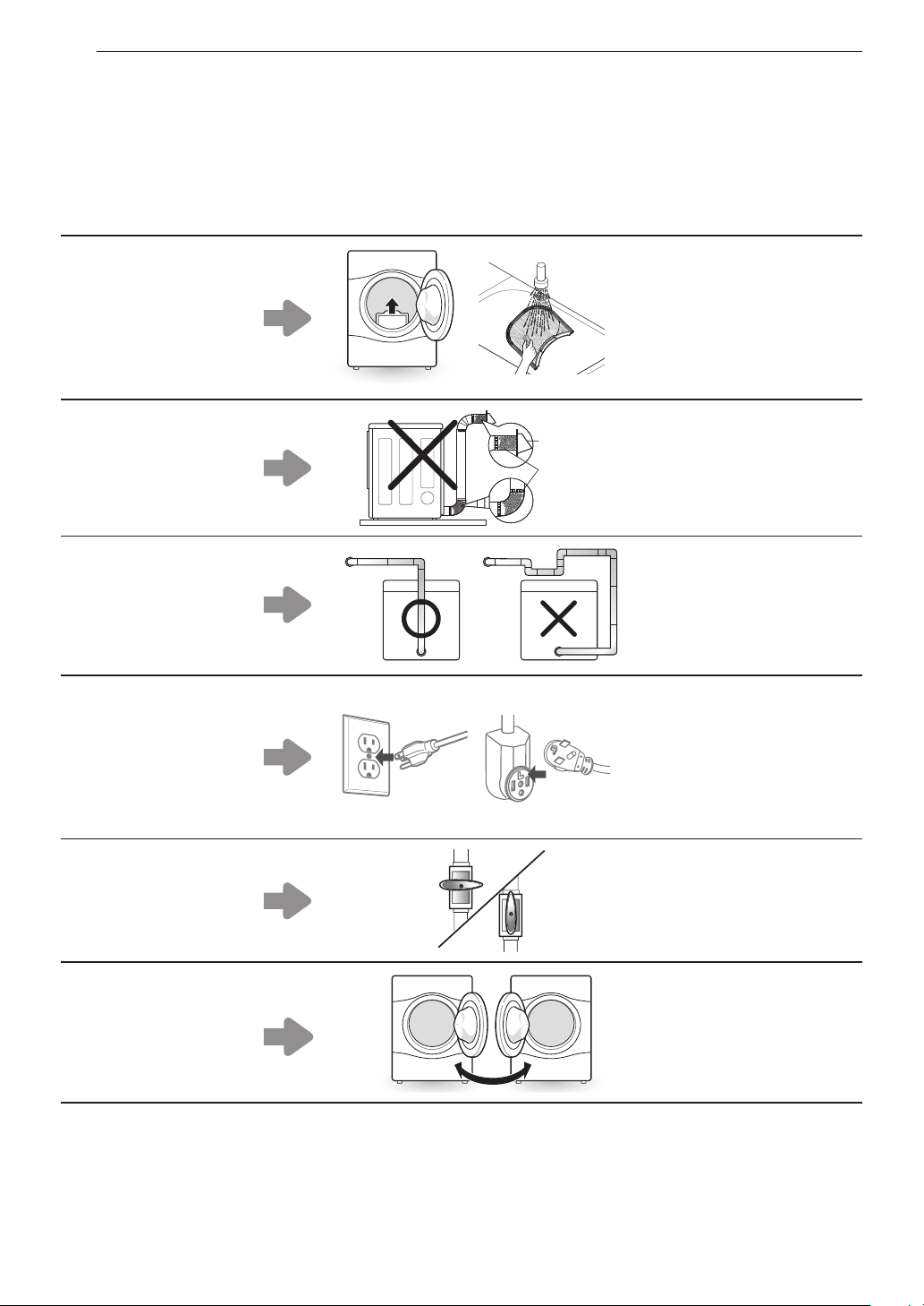
60 GARANTÍA (EE. UU.)
•
Reparaciones cuando el producto se use de otra forma que no sea uso doméstico usual y normal (p. ej., uso comercial, en
oficinas e instalaciones recreativas) o contraria a las instrucciones esbozadas en el manual del propietario del producto.
•
Costos asociados con el retiro del producto de su casa para realizar reparaciones.
•
El retiro y la reinstalación del producto si está instalado en un lugar inaccesible o no está instalado de acuerdo con las
instrucciones de instalación publicadas, lo que incluye los manuales de instalación y del propietario de LG.
•
Daños resultantes de mal uso, abuso, instalación, reparación o mantenimiento incorrectos. Una reparación incorrecta incluye el
uso de piezas no aprobadas o especificadas por LG.
•
Conversión del producto desde gas natural o L.P.
El filtro está tapado.
•
La secadora no calienta,
tiempo de secado
prolongado.
•
Limpie el filtro de pelusa.
El conducto está tapado.
•
La secadora no calienta,
tiempo de secado
prolongado.
•
Limpie la campana y el
conducto.
Conducto demasiado
largo y/o con múltiples
codos.
•
La secadora no calienta,
tiempo de secado
prolongado.
•
Mantenga los conductos
de escape lo más cortos
que sea posible y use la
menor cantidad de codos
y curvas como le sea
posible.
Cable de alimentación mal
conectado o problema
con la toma de corriente
eléctrica.
•
Sin corriente
•
No calienta
•
Vuelva a conectar el
cable de alimentación,
reemplace el fusible de la
casa o vuelva a iniciar el
disyuntor. Si el problema
es la toma de corriente,
es probable que necesite
llamar a un electricista.
La válvula de gas no está
abierta. (Secadora de
gas).
•
No calienta
•
Abra la válvula de gas.
Inversión de la puerta.
•
Las instrucciones para
la inversión de la puerta
pueden encontrarse en el
manual del usuario.
Elcostodelareparaciónoelreemplazoenestascircunstanciasexcluidasestaráacargodelconsumidor.
PARA OBTENER SERVICIO EN GARANTÍA E INFORMACIÓN ADICIONAL
Para obtener más información sobre el producto, visite el sitio web de LG en http://www.lg.com
Para obtener ayuda sobre el uso de este producto o para programar un servicio técnico, comuníquese con LG Electronics al 1-800-
243-0000 (EE. UU.).
Para obtener más información, escriba a: LG Electronics, 201 James Record Road, Huntsville, Alabama 35813

61GARANTÍA (EE. UU.)
PROCEDIMIENTO PARA RESOLVER CONFLICTOS:
TODOS LOS CONFLICTOS ENTRE USTED Y LG QUE SURJAN FUERA DE O RELACIONADOS DE ALGUNA MANERA CON
ESTA GARANTÍA LIMITADA O CON EL PRODUCTO, SE RESOLVERÁN EXCLUSIVAMENTE A TRAVÉS DE UN ARBITRAJE
VINCULANTE Y NO EN UNA CORTE DE JURISDICCIÓN GENERAL. ARBITRAJE VINCULANTE SIGNIFICA QUE USTED Y LG
RENUNCIAN AL DERECHO DE UN JUICIO CON JURADO Y A REALIZAR O PARTICIPAR EN UNA DEMANDA COLECTIVA.
Deniciones.
Para el propósito de esta sección, las referencias a “LG” signican: LG Electronics U.S.A., Inc., sus empresas matrices, subsidiarias y liales
y cada uno de sus directivos, directores, empleados, agentes, beneciarios, predecesores en interés, sucesores, cesionarios y proveedores; las referencias
a "conicto" o "reclamación" incluirán cualquier conicto, reclamo o controversia de cualquier tipo, sin importar (ya sea basado en contrato, agravio, estatuto,
regulación, ordenanza, fraude, falsa representación o cualquier teoría legal o equitativa) que surja de o esté relacionada con cualquier forma de venta, condición
o desempeño del producto o de esta Garantía Limitada.
Aviso de disputa.
En caso de que usted desee iniciar un procedimiento de arbitraje, primero debe noticar a LG por escrito al menos 30 días antes de iniciar el
arbitraje enviando una carta a LG a LG Electronics, USA, Inc. Atención: Legal Department- Arbitration 111 Sylvan Ave, Englewood Cliffs, NJ 07632. Usted y LG
aceptan participar en discusiones de buena fe en un intento de resolver su reclamo de manera amistosa. En la carta debe proporcionar su nombre, dirección
y número de teléfono; identicar el producto que es objeto de la reclamación; y describir la naturaleza del reclamo y el remedio que busca. Si usted y LG no
pueden resolver la disputa dentro de 30 días, cualquiera de las partes puede proceder a presentar una demanda de arbitraje.
Acuerdo de arbitraje vinculante y renuncia de demanda colectiva.
En caso de no resolver la disputa durante el período de 30 días después de enviar
una noticación por escrito a LG, Usted y LG se comprometen a resolver cualquier reclamo entre nosotros, solamente a través de arbitraje vinculante sobre
una base individual, a menos que usted se excluya, conforme a lo dispuesto a continuación. Cualquier conicto entre usted y LG no estarán combinados o
consolidados con una controversia relacionada con cualquier otro producto o reclamo de otra persona o entidad. Más especícamente y sin prejuicio de lo
anterior, no procederá bajo ninguna circunstancia cualquier disputa entre usted y LG como parte de una acción colectiva o representativa. En lugar del arbitraje,
cualquiera de las partes podrá iniciar una acción individual en la corte de reclamos menores, pero tales acciones en la corte de reclamos menores no podrán
ser realizadas en una acción colectiva o representativa.
Normas y procedimientos de arbitraje.
Para comenzar con el arbitraje de un reclamo, usted o LG deben realizar una demanda escrita para arbitraje. El
arbitraje será administrado por la Asociación Americana de Arbitraje (AAA) y se llevará a cabo ante un árbitro único bajo las Normas de Arbitraje del Consumidor
de la AAA, que tienen efecto al momento de inicio del arbitraje (en adelante "Normas de la AAA") y bajo los procedimientos establecidos en esta sección. Las
Normas de la AAA están disponibles en línea en www.adr.org/consumer. Envíe una copia de su solicitud de arbitraje por escrito, así como una copia de esta
disposición, a la AAA de la forma descrita en las Normas de la AAA. También debe enviar una copia de su solicitud por escrito a LG en LG Electronics, USA, Inc.
Atención: Legal Department- Arbitration 111 Sylvan Ave, Englewood Cliffs, NJ 07632. Si hay un conicto entre las Normas de la AAA y las reglas establecidas
en esta sección, prevalecerán dichas reglas de esta sección. Esta disposición de arbitraje se rige por la Ley Federal de Arbitraje. El juicio se puede introducir en
el laudo arbitral en cualquier tribunal de jurisdicción competente. Todos son temas para que el árbitro tome sus decisiones, excepto aquellos asuntos relativos
al alcance y aplicabilidad de la cláusula de arbitraje y de la capacidad de arbitraje de la controversia para que el tribunal decida. El árbitro se regirá por los
términos de esta disposición.
Legislación vigente.
La legislación del estado de su residencia regirá esta Garantía Limitada, así como todas las disputas entre nosotros, salvo que sea
invalidada o inconsistente con leyes federales aplicables.
Tarifas / Costos.
Usted no debe pagar ninguna tarifa para comenzar un arbitraje. Al recibir su solicitud de arbitraje por escrito, LG pagará todos los gastos
administrativos rápidamente a la AAA, a menos que usted solicite más de $25,000.00 por daños, en cuyo caso el pago de estos gastos se regirá por las Normas
de la AAA. Salvo disposición contraria prevista en el presente documento, LG pagará a la AAA todos los gastos documentales, administrativos y de arbitraje
para cualquier arbitraje iniciado, de conformidad con las Normas de la AAA y esta disposición de arbitraje. Si usted prevalece en el arbitraje, LG pagará los
honorarios y gastos de sus abogados, siempre y cuando sean razonables, considerando factores que incluyen, entre otros, el monto de la compra y el monto
del reclamo. No obstante lo anterior, si la ley aplicable permite una adjudicación de honorarios y gastos razonables de abogados, un árbitro puede otorgarlos en
la misma medida que lo haría un tribunal. Si el árbitro considera que la sustancia de su reclamo o la reparación solicitada en la demanda es frívola o se utiliza
para un propósito inadecuado (calicado según las normas establecidas en la Norma Federal de Procedimiento Civil 11 (b)), el pago de todos los honorarios
de arbitraje se regirá por las Normas de la AAA. En tal situación usted se compromete a reembolsar a LG todos los fondos erogados previamente por ella,
cuyo pago es, por otra parte, su obligación, según las Normas de la AAA. Salvo disposición contraria, LG renuncia a cualquier derecho que pudiera tener para
solicitarle los honorarios y gastos de sus abogados, si LG prevalece en el arbitraje.
Audiencias y ubicación.
Si su reclamo es por $25,000 o menos, usted puede optar que el arbitraje sea realizado únicamente sobre la base de: (1)
documentos presentados al árbitro, (2) a través de una audiencia telefónica o (3) por una audiencia en persona, según lo establecido por las Normas de la
AAA. Si su reclamo excede $25,000, el derecho a una audiencia estará determinado por las Normas de la AAA. Cualquier audiencia de arbitraje en persona
se realizará en un lugar dentro del distrito judicial federal en el cual resida, a menos que ambos acuerden otra ubicación o estemos de acuerdo con el arbitraje
telefónico.
Exclusión.
Usted puede quedarse fuera de este procedimiento de resolución de la disputa. Si se excluye, ni usted ni LG pueden solicitar al otro que participe
en un procedimiento de arbitraje. Para excluirse usted debe enviar una noticación a LG, en un lapso de hasta 30 días continuos, contados a partir de la fecha
de la primera compra del consumidor del producto, ya sea por: (i) el envío de un correo electrónico a [email protected] con el siguiente Asunto: "Exclusión del
arbitraje" o (ii) llamada al 1-800-980-2973. Debe incluir en el correo electrónico de exclusión o suministrar por teléfono: (a) su nombre y dirección; (b) la fecha en
la cual el producto fue comprado; (c) el nombre o el número del modelo del producto; y (d) el número del serial (el número del serial puede ser hallado (i) en el
producto, o (ii) en la dirección de https://www.lg.com/us/support/repair-service/schedule-repair-continued al hacer clic en “Find My Model & Serial Number”).
Sólo puede excluirse del procedimiento de resolución de conictos en la forma descrita anteriormente (es decir, por correo electrónico o por teléfono); ninguna
otra forma de noticación será efectiva para hacerlo. Excluirse de este procedimiento de resolución de controversias no afectará de ninguna manera la
cobertura de la Garantía Limitada, por lo que usted continuará disfrutando de todos sus benecios. Si conserva este producto y no se excluye, usted acepta
todos los términos y condiciones de la cláusula de arbitraje descrita anteriormente.

Memo


This product qualifies for ENERGY STAR in the “factory
default (Home Use)” setting. Changing the factory default
settings or enabling other features may increase power
consumption that could exceed the limits necessary to
qualify for ENERGY STAR .
LG Customer Information Center
Register your product Online!
www.lg.com
1-800-243-0000
USA
1-888-542-2623
CANADA
For inquiries or comments,
visit www.lg.com or call:
