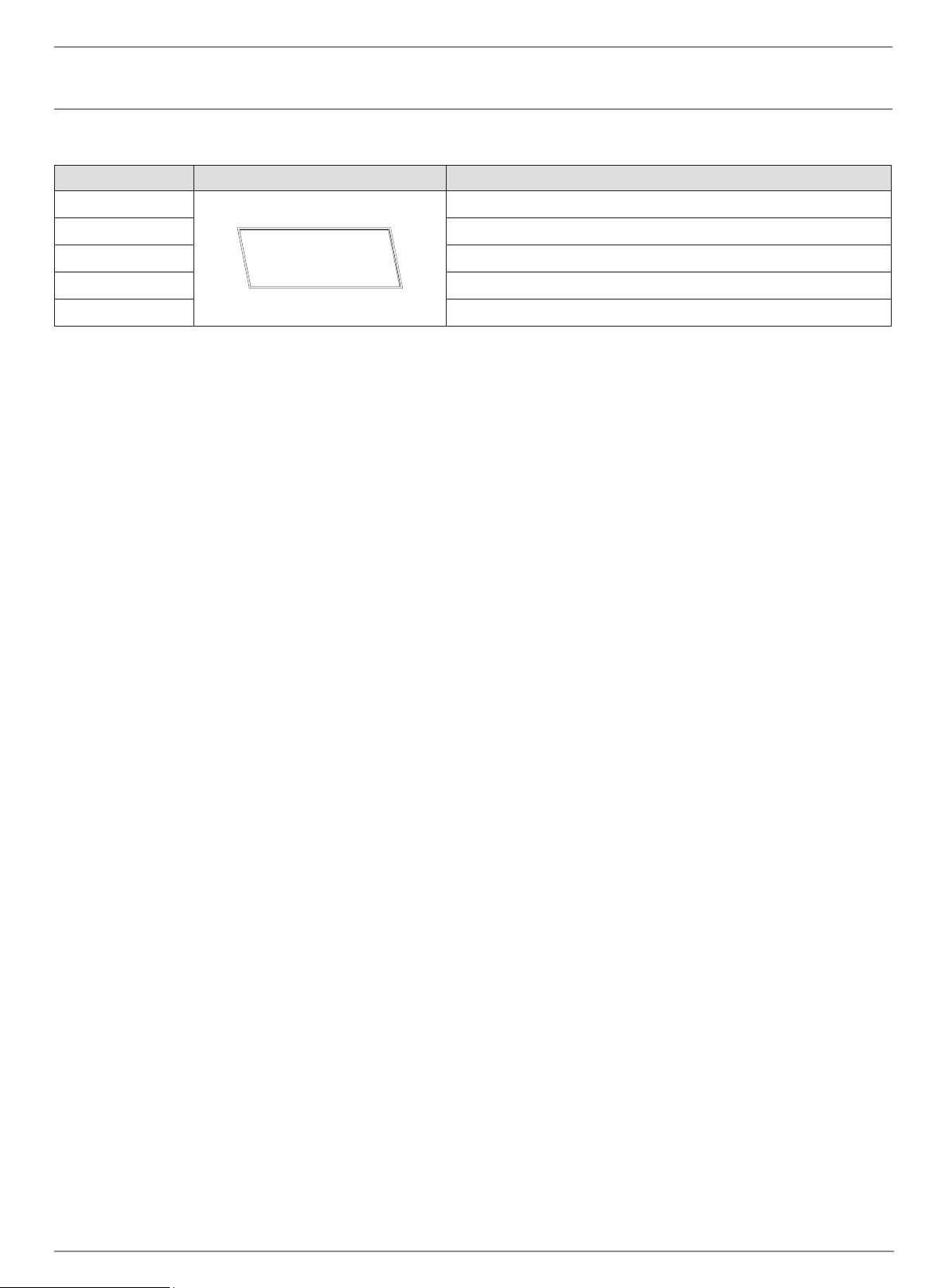
ELECTRIC SERIES
INSTALLER: LEAVE THIS MANUAL WITH THE APPLIANCE.
CONSUMER: RETAIN THIS MANUAL FOR FUTURE REFERENCE.
INSTALLATION,
OPERATION
AND MAINTENANCE
MANUAL
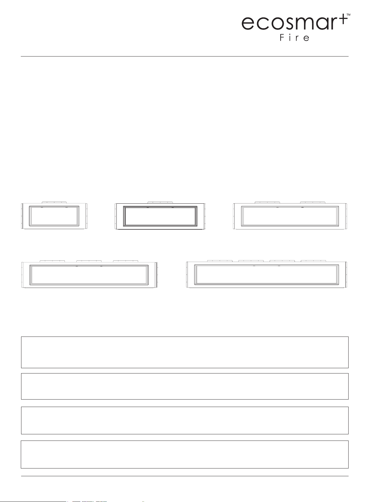
EL120
98.95kg, 218.15lbs
EL100
88.75kg, 195.66lbs
EL40
44kg, 97lbs
EL80
69.15kg, 152.34 lbs
EL60
55.65kg, 122.69lbs
PLEASE READ THESE INSTRUCTIONS COMPLETELY BEFORE OPERATING THE ECOSMART™ FIRE.
FAILURE TO FOLLOW THEM COULD CAUSE A HEATER MALFUNCTION RESULTING IN SERIOUS
INJURY AND/OR PROPERTY DAMAGE.
WARNING: ALL ELECTRIC HEATERS HAVE HOT AND ARCING OR SPARKING PARTS INSIDE. DO NOT
USE IT IN AREAS WHERE GASOLINE, PAINT OR FLAMMABLE LIQUIDS ARE OR ARE STORED.
THIS FIREPLACE MEETS THE CONSTRUCTION AND SAFETY STANDARDS OF H.U.D. FOR
APPLICATION IN MANUFACTURED HOMES WHEN INSTALLED ACCORDING TO THESE INSTRUCTIONS.
ecosmartre.com
ENGLISH
2
WARNING: Improper installation, adjustment, alteration, service
or maintenance can cause injury or property damage. Refer to
this manual. For assistance or additional information, consult a
qualied installer.
CAUTION: Do not expose the heater to the elements
(such as rain, etc).
Do not place clothing or other ammable material on or near
rebox. Never place any objects on the replace.
Carefully supervise young children when they are in the room
with replace.
Fireplace becomes very hot when running. Keep children
and adults away from hot surfaces to avoid burns or clothing
ignition. Fireplace will remain hot for a time after shutdown.
Allow surfaces to cool before touching.
CAUTION: In order to avoid overheating, do not cover the heater.
IMPORTANT INSTRUCTIONS
When using electrical heaters, basic precautions should always be
followed to reduce the risk of re, electric shock and injury to
persons, including the following:
1. Read all instructions before installing or using this heater.
2. This heater is hot when in use. To avoid burns, do not let bare skin
touch hot surfaces. Keep combustible materials, such as furniture,
pillows, bedding, papers, clothes, and curtains at least 3 feet (0.9m)
from the front of the heater and keep them away from the sides
and rear.
3. Extreme caution is necessary when any heater is used by or near
children or invalids and whenever the heater is left operating and
unattended.
4. Do not operate any heater after it malfunctions. Disconnect power
at service panel and have heater inspected by a reputable electrician
before using.
5. Do not use outdoors.
6. To disconnect heater, turn controls to o and turn o power to heater
circuit at main disconnect panel.
7. Do not insert or allow foreign objects to enter any ventilation or
exhaust opening as this may cause an electric shock or re, or
damage the heater.
8. To prevent a possible re, do not block air intakes or exhaust in any
manner.
9. A heater has hot and arcing or sparking parts inside. Do not use it in
areas where gasoline, paint or ammable vapors or liquids are used or
stored.
10. Use this heater only as described in this manual. Any other use not
recommended by the manufacturer may cause re, electric shock or
injury to persons.
11. SAVE THESE INSTRUCTIONS
© Copyright 2004 - 2022 MAD Design USA. All rights reserved. V0422
3
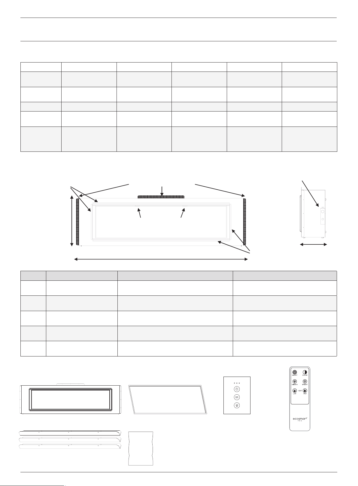
POWER DATA
PRODUCT GUIDE
BOX CONTENTS
EL40 EL60 EL80 EL100 EL120
Volts/HZ Amps AC 120V/60Hz
15 Amps
AC 120V/60Hz
15 Amps
AC 120V/60Hz
15 Amps
AC 120V/60Hz
15 Amps
AC 120V/60Hz
15 Amps
Heater AC 120V/60Hz
750W/1500W
AC 120V/60Hz
750W/1500W
AC 120V/60Hz
750W/1500W
AC 120V/60Hz
750W/1500W
AC 120V/60Hz
750W/1500W
Lamps LED 12V LED 12V LED 12V LED 12V LED 12V
Rotor motor AC 120V/60Hz 4W
CCW 15/18 r/min
AC 120V/60Hz 4W
CCW 15/18 r/min
AC 120V/60Hz 4W
CCW 15/18 r/min
AC 120V/60Hz 4W
CCW 15/18 r/min
AC 120V/60Hz 4W
CCW 15/18 r/min
Shipping Size 58” x 26” x 14”
1473mm x 660mm x
356mm
78” x 26” x 14”
1981mm x 660mm
x 356mm
98” x 26” x 14”
2489mm x 660mm
x 356mm
118” x 26” x 14”
2997mm x 660mm
x 356mm
138” x 26” x 14”
3505mm x 660mm
x 356mm
Model Viewing Area Firebox Dimensions Framing Dimensions
EL40 40” W x 15” H
1016mm W x 381mm H
54 3/4” W x 22 1/2” H x 11 1/2” D
1391mm W x 572mm H x 292mm D
55 3/4” W x 23” H x 12” D
1416mm W x 548mm H x 305mm D
EL60 60” W x 15” H
1524mm W x 381mm H
74 3/4” W x 22 1/2” H x 11 1/2” D
1899mm W x 572mm H x 292mm D
75 3/4” W x 23” H x 12” D
1924mm W x 548mm H x 305mm D
EL80 80” W x 15” H
2032mm W x 381mm H
94 3/4” W x 22 1/2” H x 11 1/2” D
2407mm W x 572mm H x 292mm D
95 3/4” W x 23” H x 12” D
2432mm W x 548mm H x 305mm D
EL100 100” W x 15” H
2540mm W x 381mm H
114 3/4” W x 22 1/2” H x 11 1/2” D
2915mm W x 572mm H x 292mm D
115 3/4” W x 23” H x 12” D
2940mm W x 548mm H x 305mm D
EL120 120” W x 15” H
3048mm W x 381mm H
134 3/4” W x 22 1/2” H x 11 1/2” D
3423mm W x 572mm H x 292mm D
135 3/4” W x 23” H x 12” D
3448mm W x 548mm H x 305mm D
1 x Remote
Electric Access
Plate (see page 6)
L Metal Nailing Flanges
(NOTE: Flange quantity and placement
will vary based on model)
Glass Pull Tabs
Width varies (see chart below)
1/2” (13 mm)
Drywall
Stop x 4
1/2” (13 mm)
Drywall
Stop x 4
11 1/2” (292mm)
(all models)
22.5” (572 mm)
(all models)
1 x Fire Unit 1 x L Metal Deco Trim
PRODUCT SPECIFICATIONS
L Metal Nailing Flanges (with screws)
*Quantity varies by model
1 x Tethered Wall Control
Glass Media
*The number of bags
vary by model.
ecosmartre.com
ENGLISH
4
CAUTION: Do not locate in a moist room such as a bathroom or
laundry room.
CAUTION: Wear gloves and safety glasses for protection during
installation and maintenance.
INSTALLATION
WARNING: If the information in these instructions is not
followed exactly, a re or explosion may result casing property
damage, personal injury or death.
WARNING - RISK OF FIRE!
To prevent a possible re, do not block air intake or exhaust in
any manner. Do not use on soft surfaces where openings may
become blocked.
WARNING - RISK OF FIRE!
Do not blow or place insulation against the rebox.
To reduce the risk of re do not store or use gasoline or other
ammable vapors in the vicinity of this or any other heater.
CAUTION: Keep combustible materials, such as furniture,
pillows, bedding, papers, clothes and curtains at least 3 feet
(0.9m) from the front of the heater and keep them away from
the sides and rear.
INSTALLING FIREPLACELOCATING FIREPLACE
Select a suitable location that is not susceptible to moisture and is a
safe distance from drapes, furniture and high trac areas. A qualied
electrician should add a exible 15 amp 120 volt circuit per local
building codes.
Note: Follow all national and local electrical codes.
© Copyright 2004 - 2022 MAD Design USA. All rights reserved. V0422
5
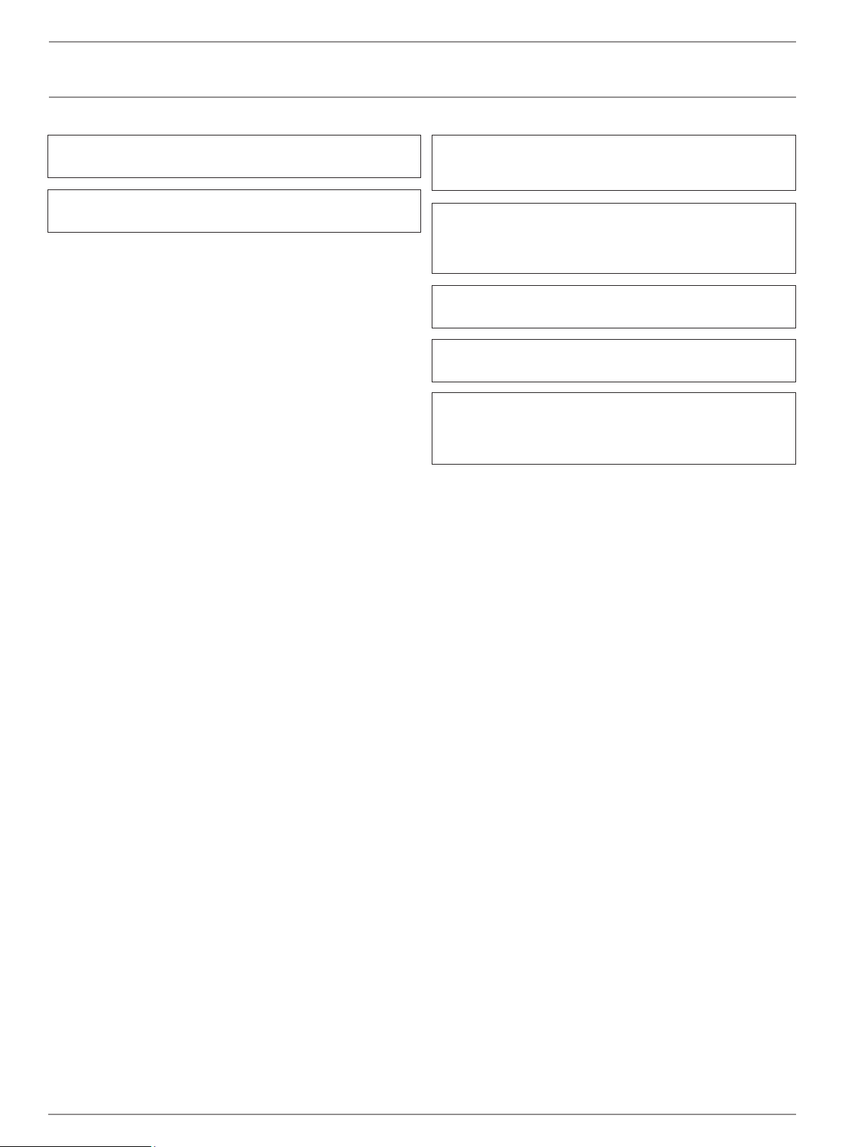
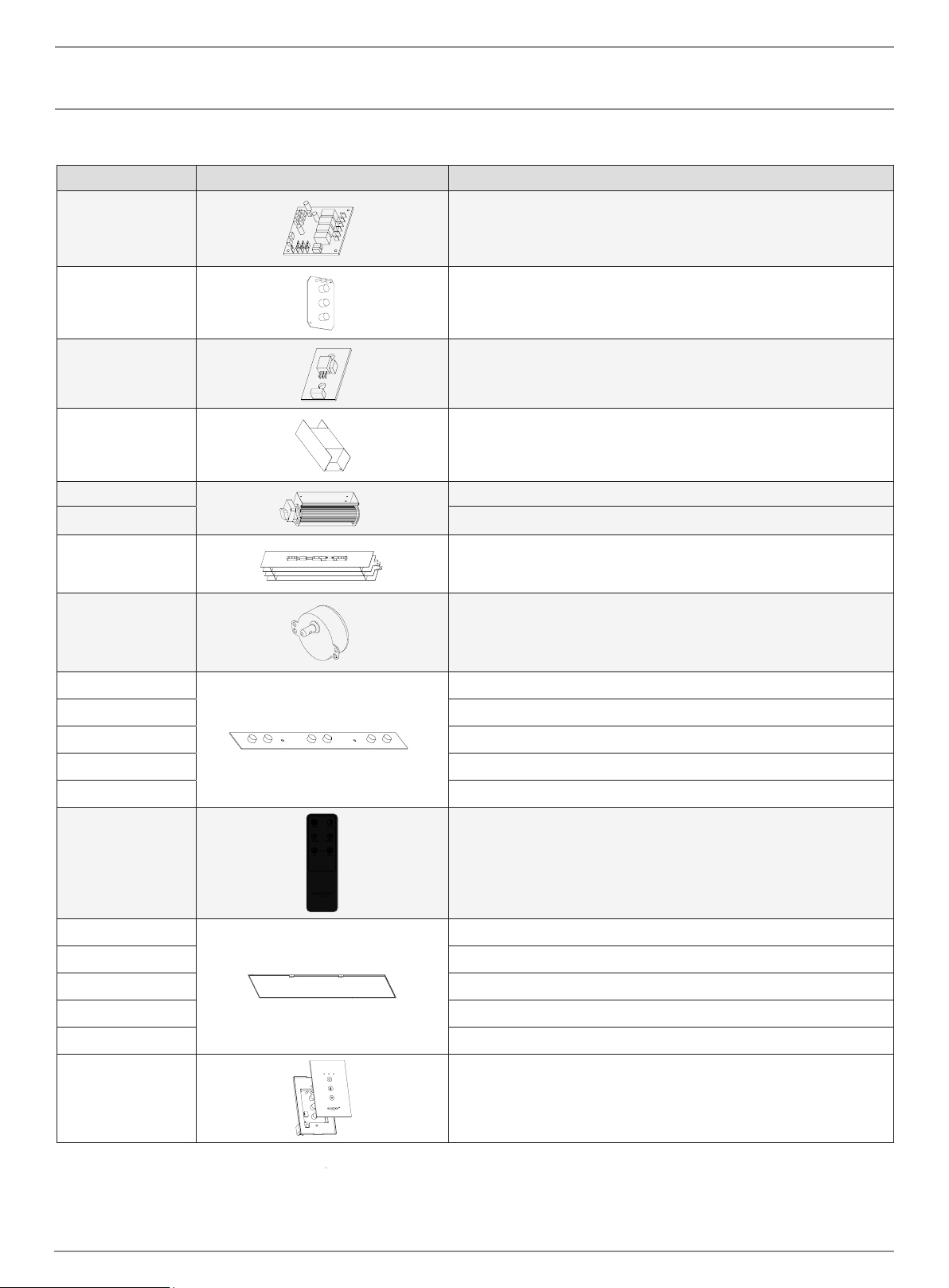
2. Install L shaped metal nailing ames onto replace.
3. Connect hard wire to the terminal block according to the diagram
below. Choose any connector type according to local building code.
1. Prepare the framed opening using wood or metal studs according to
the Framing Dimensions chart
4. Install the re unit in the framed opening with a minimum 1 ¼
(32mm) drywall screws to secure the unit.
5. Mask the exposed re unit during the drywall process. Install drywall
to the drywall stops on the perimeter of the re insert. For more
information on the drywall stops see the Product Guide on page 3.
Decorate as desired.
6. After installation, user may elect to use the L Metal Deco Trim. To
install, use a small amount of construction adhesive and secure to
the drywall face.
INSTALLATION
To be performed by a qualied electrician according to
local building codes.
Terminal Block
FRAMING DIMENSIONS
Model W H D
EL40 55 3/4” (1416mm) 23” (584mm) 12” (305mm)
EL60 75 3/4” (1924mm) 23” (584mm) 12” (305mm)
EL80 95 3/4” (2432mm) 23” (584mm) 12” (305mm)
EL100 115 3/4” (2940mm) 23” (584mm) 12” (305mm)
EL120 135 3/4” (3448mm) 23” (584mm) 12” (305mm)
H
W
D
ecosmartre.com
ENGLISH
6
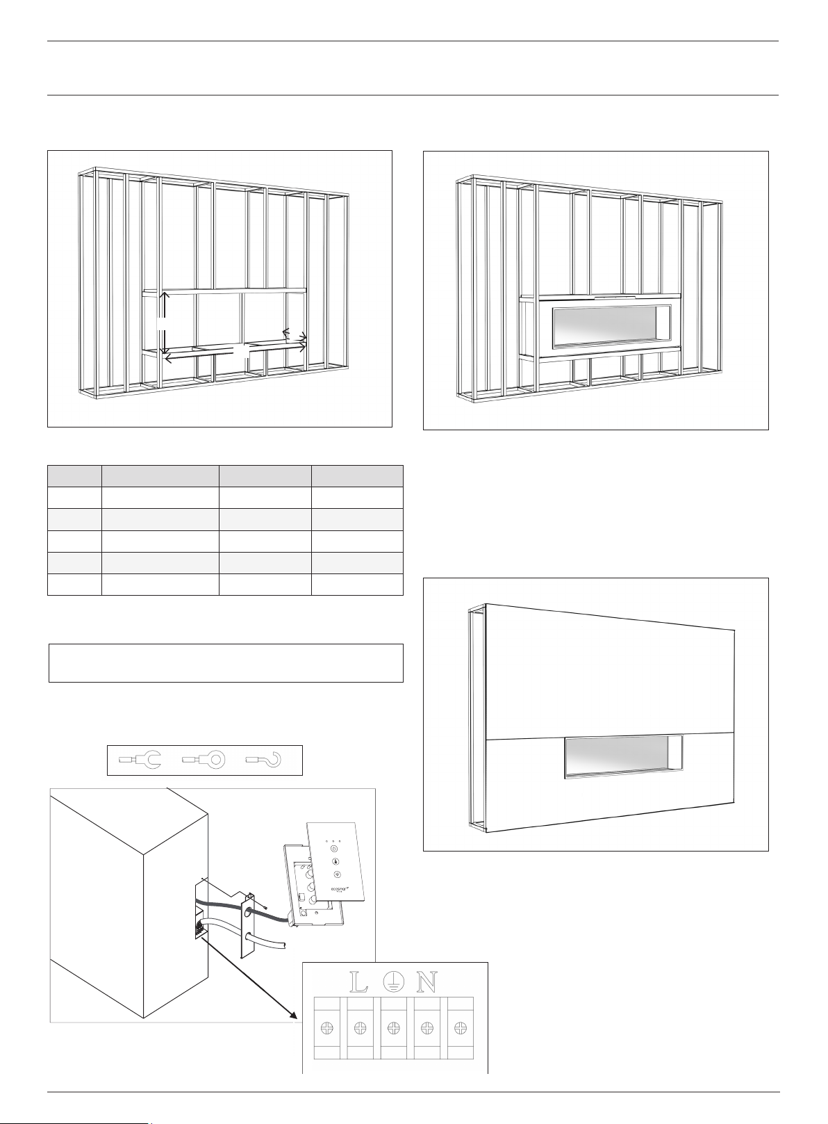
OPTIONAL INSTALLATIONS
If you decide not to install the Wired Touch Control in the wall, IT
IS IMPORTANT YOU LEAVE THIS WIRED TO THE UNIT. Leave it
stored inside the compartment near the terminal block where you
originally found it. Please do not cut the cord or unplug the wires
from the touch control because the replace will not work properly.
Installing the Wired Touch Control
1. Locate and remove the access door on the rear right side of the
re unit.
2. Locate the Wired Touch Control directly inside the access panel. Pull
the touch control through the access panel and replace the access
door. Locate the touch control anywhere within cable length.
3. The wiring of the Wired Touch Control cannot be located near high
voltage wires (110V) as this may eect performance of the touch
control. Keep all high voltage power at least 12” (305mm) from the
touch control and touch control wiring. The touch control includes 12
feet of wiring. Do not add or remove or cut the wiring.
Indicator Lights
When all indicator lights are o, touching any button will only show the
status. Once the indicator lights are on you can begin operation. Touch
the power button to turn the machine on. This will be indicated by 1
orange LED light. The Heat button can be pressed multiple times and
will turn on low, high and o in that order. The Backlight button turns on
high, medium, low and o in that order.
The unit is hardwired and has no main switch. (Caution: If servicing this
unit, turn o power at the main circuit breaker.) An optional tethered
wall control switch is included, refer to installation instructions to
relocate the tethered wall control switch to a wall location.
The included Wired Touch Control functions in the same manner as the
buttons on the tethered wall control switch.
INSTALLATION
The status light above shows that the power
is on and the heater is on low.
The status light above shows that the power
is on and the heater is on high
When the switch turns on, this orange
pilot lamp is always on. It shows the re is
energized.
Power
Heat
Backlight
© Copyright 2004 - 2022 MAD Design USA. All rights reserved. V0422
7
OPERATION
Installing Optional Log Set
1. Remove the inner glass panel by rst removing the 2 screws in the
nger pull tabs (nger pull tabs are located on the top of the glass
panel.) Tilt the glass face down about 45 degrees and remove the
glass. Store the glass panel upright (not on it’s face) in a safe place.
CAUTION: There are locator pins on the bottom of the glass panel.
Lift gently to avoid damaging the pins and unit face
2. Follow the instructions included with the optional log set.
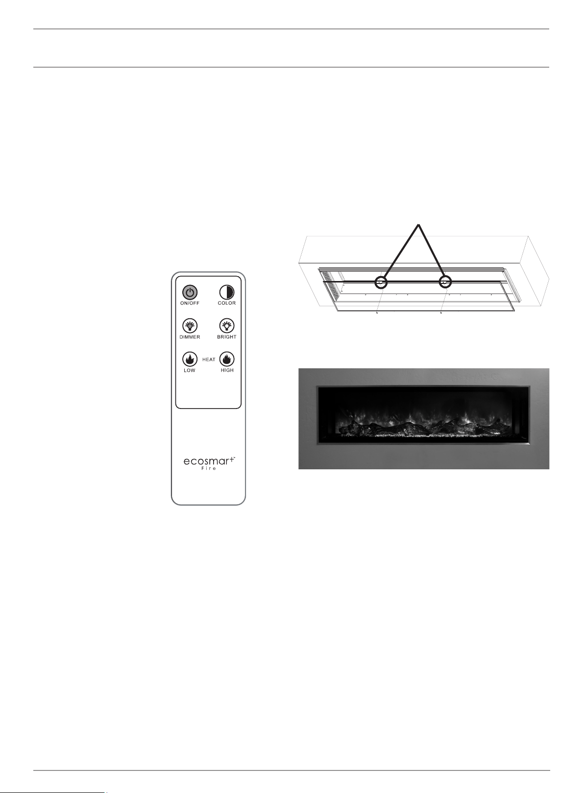
Finger pull tabs
1. Press to turn unit on / o
2. Press to dim ame
3. Press for low heat
4. Press to change ame from
orange to blue
5. Press to brighten ame
6. Press for high heat
Remote
The On/O button toggles the unit on or o. The Color button toggles
the ame image from orange to blue. The Dimmer button will lower the
brightness of the ame and turn the ame o at the lowest setting. The
Bright button will make the re image brighter. Press the Heat button for
low heat (5000BTU). Press the Heat button for high heat (10000BTU).
Press either of these buttons twice to turn the heat o.
NOTE: The indicator lights on the wall switch as well as the main unit
will only notify you the heat setting is on.
Pairing the Remote
To pair remote, turn o the re unit at the main power switch for 30
seconds. Hold the On/O button on the remote while ipping the main
power switch back to on. When the re unit powers up, the remote will
be paired.
1
2
3
4
5
6
ecosmartre.com
ENGLISH
8
MAINTENANCE
ITEM PHOTO DESCRIPTION
ESF.1.EL.P.PCB Electric Printed circuit board
ESF.1.EL.P.LCD Electric LCD Touch Control
ESF.1.EL.P.REM.IRC Electric Remote Control IR Receiver
ESF.1.EL.P.TRA Electric Transformer
ESF.1.EL.P.HF.RH Electric Right hand Heater Fan
ESF.1.EL.P.HF.LH Electric Left hand Heater Fan
ESF.1.EL.P.HTR Electric Heater
ESF.1.EL.P.MTR Electric Spindle Motor
ESF.1.EL.P.LED40 Electric LED 40
ESF.1.EL.P.LED60 Electric LED 60
ESF.1.EL.P.LED80 Electric LED 80
ESF.1.EL.P.LED100 Electric LED 100
ESF.1.EL.P.LED120 Electric LED 120
ESF.1.EL.P.REM Electric Remote Control
ESF.1.EL.P.GL40
Electric Innerglass 40
ESF.1.EL.P.GL60 Electric Innerglass 60
ESF.1.EL.P.GL80 Electric Innerglass 80
ESF.1.EL.P.GL100 Electric Innerglass 100
ESF.1.EL.P.GL120 Electric Innerglass 120
ESF.1.ELP.TWS Electric Wired Touch Control
SERVICE PARTS
© Copyright 2004 - 2022 MAD Design USA. All rights reserved. V0422
9
MAINTENANCE
ITEM PHOTO DESCRIPTION
ESF.1.EL.P.MDT40 Electric Metal Deco Trim 40
ESF.1.EL.P.MDT60 Electric Metal Deco Trim 60
ESF.1.EL.P.MDT80 Electric Metal Deco Trim 80
ESF.1.EL.P.MDT100 Electric Metal Deco Trim 100
ESF.1.EL.P.MDT120 Electric Metal Deco Trim 120
FREQUENTLY ASKED QUESTIONS
Q. How do you program the remote control?
A. The remote comes pre-programmed. No programming is necessary.
Q. What distance can the remote be used from the replace?
A. Optimal distance for the remote control is within 20 feet (6 meters) of
the replace.
Q. Can you turn on the replace via the touch screen and o via the
remote (or vise versa)?
A. Yes.
Q. How long will the LED lights last?
A. LED Lamps have a life span of up to 20 years.
Q. Can the sensitivity of the touch screen be adjusted?
A. Yes, but only by the factory. Not just any technician will be able to
adjust the touch screen sensitivity.
Q. Can the replace be installed outside?
A. No. Please review the entire safety chapter before installing this
replace.
Q. Does the replace need to be on a dedicated 15 amp circuit?
A. Yes.
Q. What thickness of sheetrock should be used for the recessed
installation?
A. 1/2” (13mm) or 5/8” (16mm).
Q. How often do the batteries in the remote need to be replaced?
A. Annually, possibly more with heavy use.
Q. Is there a remote receiver in the replace that requires batteries?
A. No, only the remote transmitter requires batteries. The rest of the
replace operates entirely o the main power supply
ecosmartre.com
ENGLISH
10
MAINTENANCE
PROBLEM POSSIBLE CAUSE CORRECTIVE ACTION
Flame is not visible when unit is turned on
A. Wiring is loose
A. Disconnect unit from power source and
inspect for loose connections
B. Motherboard is defective B. Replace motherboard
Fireplace lights up but there is no ame image
A. Wiring for motor is loose
A. Disconnect unit from power source and
inspect for loose connections from motor
B. Motor is defective B. Replace motor
Fireplace is squeaking when ame image is on
A. Fireplace spindle/ rod is contacting to metal
A. Apply lithium grease or any standard grease
to contacts with rod and metal
B. Motor is defective B. Replace motor
Nothing comes on (touch screen, etc.)
A. Breaker tripped or circuit has no power A. Reset breaker, test circuit for power
B. Internal component is frozen and needs to
be reset
B. Turn power o at the main breaker for 20
seconds. Turn power back on.
C. Defective component C. Qualied service technician needs to replace
motherboard, transformer or LCD touch control.
Touch Screen Comes on - then nothing
A. Fireplace is not plum to the wall (there is
space between the touch screen and fascia)
A. Reposition the replace in the installation
so the glass fascia rests rmly to the replace
touch controls. Check that fascia is seated
correctly on pins
B. Fireplace was installed with the power in
“on” position
B. Turn the main breaker to the “o” position
for 30 seconds. Next ip the breaker back into
the “on” position for 20 seconds for complete
reboot of touch control.
C. Not operating touch control properly with
nger
C. Press at part of nger rmly on the touch
screen and apply moderate pressure
D. Loose connection on motherboard
D. Check functions with remote control. If
functional, check connections on motherboard
E. Motherboard is defective E. Replace Motherboard
Fireplace turns o and will not turn back on
A. Fireplace has overheated and safety disc
has snapped or circuit breaker has tripped
A. Turn the main circuit breaker to the “o”
position for 30 seconds. Next, turn the
breaker back to the “on” position. Unit will
reboot and safety disc will reset. Ensure there
are no obstructions to the air inlet or air outlet
areas around the replace.
Can operate replace functions with touch
controls but not remote control
A. Low Batteries
A. Replace batteries in remote control with -
CR2025
B. Remote not paired properly
B. To pair remote, turn o the re unit at the
main power switch for 30 seconds. Hold the
On/O button on the remote while ipping the
main power switch back to on. When the re
unit powers up, the remote will be paired.
C. Remote control defective C. Replace remote control
D. Remote Sensor is defective D. Replace remote sensor inside replace
Heater does not provide heat when on
A. Wiring is loose
A. Disconnect unit from power source and
inspect for loose connections
B. Thermal snap disc has been tripped
B. Turn the main breaker to the “o” position
for 30 seconds. Next ip the breaker back into
the “on” position.
C. Heater core is defective C. Replace Heater Core
TROUBLESHOOTING
© Copyright 2004 - 2022 MAD Design USA. All rights reserved. V0422
11
MAINTENANCE
CLEANING AND MAINTENANCE INSTRUCTIONS
There is very little maintenance involved with your electric replace.
Please follow the few points below:
• On a semi-annual basis unplug the machine from it’s power source
and wait for the heating element to cool, remove the glass face of
the replace and dust the re unit with a dry cloth. Be careful not to
brush any wires that may be exposed as you do this.
• To clean the glass face of the replace simply use your desired glass
cleaner with paper towels.
• To clean the air inlets/outlets, wipe with a soft cloth or the nozzle of a
vacuum cleaner
• Dust can easily build up around the heater area under the appliance.
Take particular care to clean this area on a regular basis to prevent
buildup.
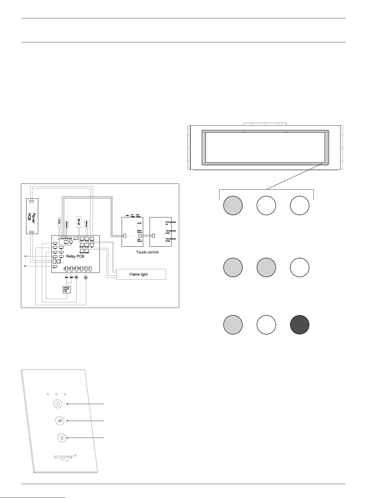
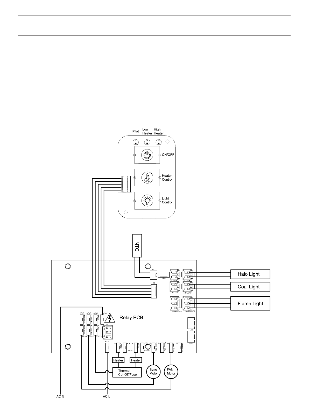
WIRING DIAGRAM
ecosmartre.com
ENGLISH
12
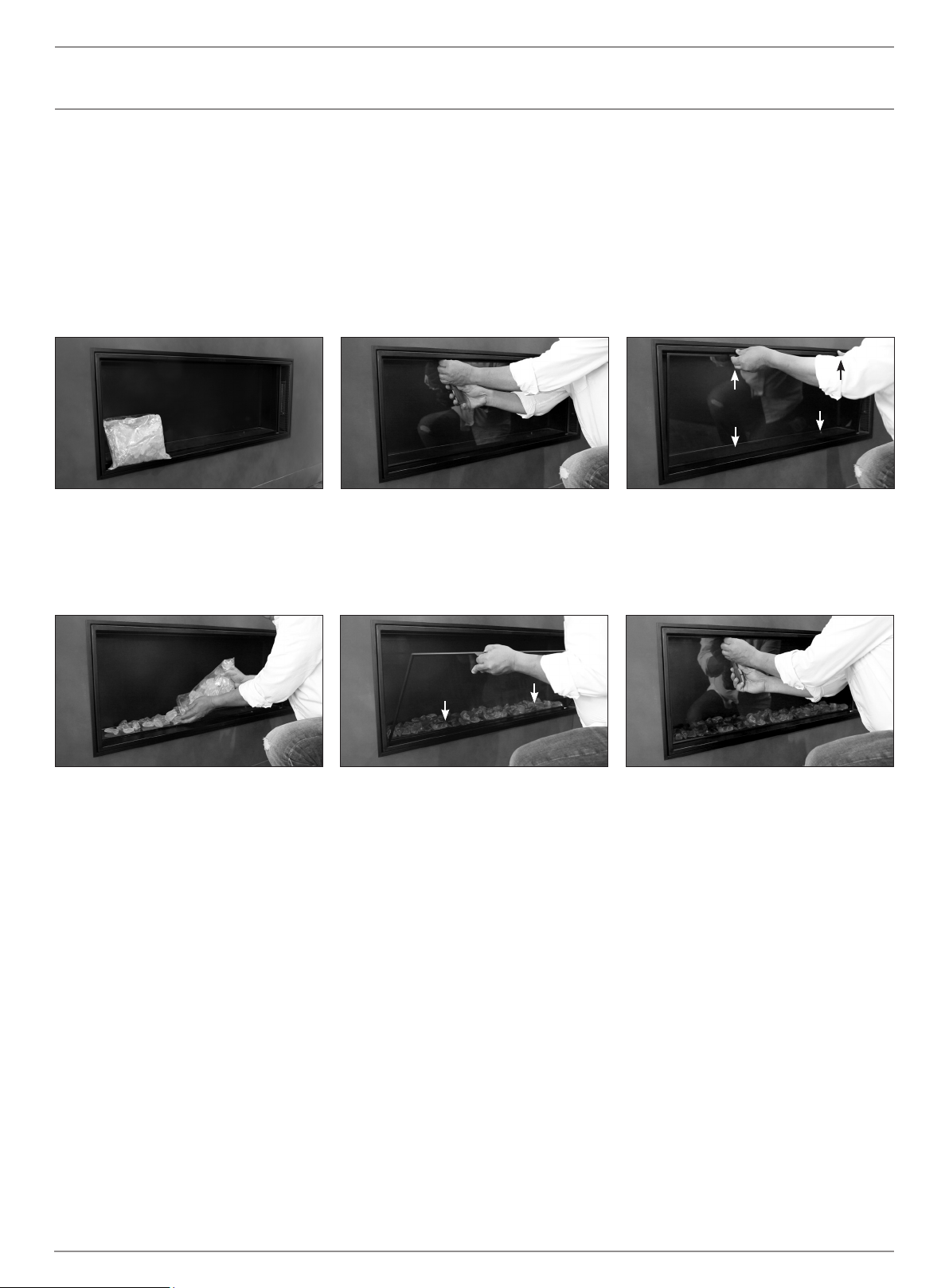
Glass Media
Install the glass media by following these instructions
Step 1: Before beginning installation, locate
the glass media.
Step 4: Evenly place the desired amount of
glass media on the clear strip.
Step 5: To reattach the glass panel, locate
the bottom two pins and insert into the holes.
Then carefully tilt into place.
Step 2: Remove the two screws secured at the
top of the glass panel.
Step 6: Re-attach screws and tighten until the
glass panel is secure.
Step 3: Pull the upper tabs and tilt the glass
towards you. Then carefully lift and detach
from the bottom two pins.
PIN
TAB
TAB
PIN
PIN
PIN
© Copyright 2004 - 2022 MAD Design USA. All rights reserved. V0422
13
Your Warranty
Your EcoSmart Fire is covered by a transferable limited warranty and a
solid service and support network should you need it. In the unlikely event
of a problem occurring due to a manufacturing fault within 12 months from
the date of purchase of the appliance, parts will be supplied for repair
of the product or the product will be replaced free of charge. Repair or
replacement is at the option of Mad Design USA. At Mad Design USA,
we believe in supplying you with the best, most user friendly replace and
providing you with the means to keep it that way. Many aspects of the
EcoSmart Fire are hand-produced, hand-nished and use natural materials,
which makes them subject to variations in nish and size.
All of our pieces will mature and age over the course of time, through natural
processes associated with use and with heat and ame. These changes are
an essential part of the dynamic of the piece. Mad Design USA reserves the
right to make minor amendments without prior notice.
The Warranties set out are express Warranties given by the
manufacturer and are in addition to the rights and remedies which
are conferred upon consumers by the Competition and Consumer
Act 2010 of the Commonwealth and other Commonwealth, State or
Territory legislation.
Service under the warranties set out above must be provided by
Mad Design USA Authorised Customer Service Centre which shall
provide service during their normal working hours.
This warranty certicate along with proof of date of purchase
must be produced when making any claim.
FIRST NAME
LAST NAME
EMAIL
CITY STATE ZIP
COUNTRY
DATE OF PURCHASE
PURCHASED FROM
PRIMARY USE
MODEL NAME
SERIAL NUMBER
You will nd this on the dataplate on the side of the burner.
For warranty claims please contact your local distributor. If there is not
a local distributor in your country please visit www.ecosmartre.com
to source the details of the country closest to you.
*Do not return this form to Mad Design USA, please retain for your own
reference.
Length of warranty Mad Design USA undertakes to: The express warranties do not include:
12 MONTHS WARRANTY FROM
DATE OF PURCHASE ON GLASS
AND STEEL PARTS INCLUDING
RAW AND POWDER COATED.
Chips and scratches are not
covered by warranty.
Repair or, at our option, replace
without cost to owner either for
materials or labour, any part that
is found to be defective.
A. Service calls to:
1. Correct the installation of the Fire.
2. Instruct you how to use the Fire.
B. Repairs when the EcoSmart Fire has been used in other than
normal domestic/commercial use or when not used in accordance
with the Installation, Operating and Maintenance Manual or operation
with an incorrect power source.
C. Repairs when the EcoSmart Fire parts or models have been
modied or altered in any way that has not been approved in writing by
Mad Design USA.
D. Repairs when the Fire has been dismantled, repaired or serviced by
anyone other than an authorised representative of Mad Design USA.
E. Pick up and delivery.
F. Normal maintenance as required in the Installation, Operating and
Maintenance Manual supplied with the EcoSmart Fire.
G. Transportation or traveling costs involved in the repair when the
appliance is installed outside Mad Design USA’s AUTHORISED
CUSTOMER SERVICE CENTRES’s normal service area.
H. Damage to the Fire caused by accident, misuse or Act of God.
I. Any incidental shipping or holding costs to deliver your Fire or
parts to an Authorized Customer Service Centre.
J. Consumable items such as the bulbs and fuses.


MAD Design USA
5875 Green Valley Circle, Suite 100
Culver City CA 90230
T + 1 (888) 590.3335 E [email protected]
V0422
This product is distributed by EcoSmart Inc
DBA MAD Design USA.