Loading ...
Loading ...
Loading ...
Assembly of the trimmer guard and the
trimmer head
To attach the trimmer guard
1. Attach the plate holder to the gear with the smallest
bolt. Tighten the bolt.
2. Attach the trimmer guard to the plate holder.
3. Attach the biggest bolt and tighten it.
To remove the trimmer guard
1. Remove the bolts.
2. Remove the trimmer guard.
To attach the trimmer head T35 (535iFR, 535iRX)
1. Put the drive disc (B) on the output shaft.
2. Turn the output shaft to align one of the holes in the
drive disc with the related hole in the gear housing.
3. Put the locking pin (C) in the hole to lock the shaft.
4. Turn the trimmer head (H) counterclockwise to
attach.
H
B
C
To remove the trimmer head T35 (535iFR, 535iRX)
1. Put the locking pin (C) in the hole to lock the shaft.
2. Turn the trimmer head (H) clockwise to remove it.
3. Remove the drive disc (B) from the output shaft.
H
B
C
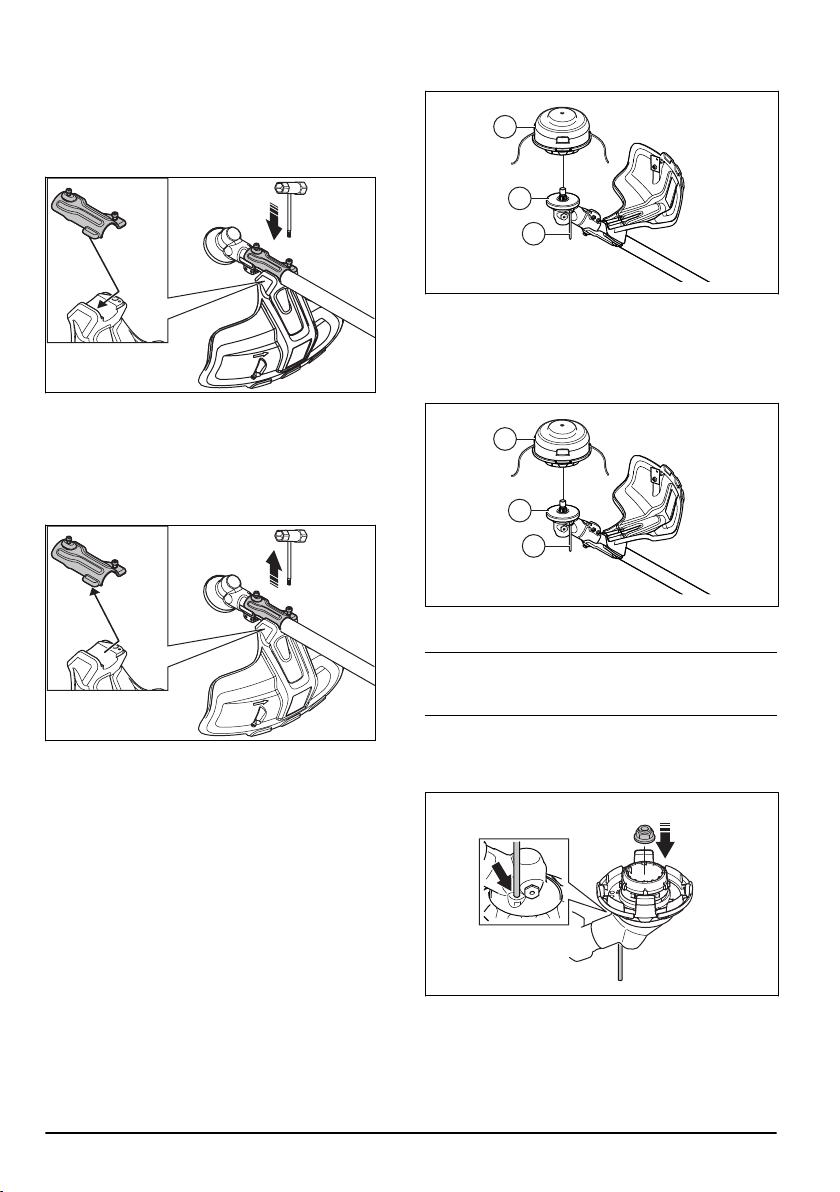
To attach the trimmer head E35B (535iRXT)
Note:
To increase the life of the cord it can be soaked in
water for a couple of days before it is assembled. This
will make the cord tougher.
1. Put the locking pin into the hole to lock the shaft.
2. Attach the trimmer head.
3. Install the nut.
4. Install the line chute assembly.
14
609 - 002 - 27.06.2019
Loading ...
Loading ...
Loading ...