14
13
12
00
11
GROUP INDEX
15
17
GENERAL .............................................
ENGINE .................................................
LUBRICATION ......................................
FUEL AND ENGINE CONTROL ...........
COOLING ..............................................
INTAKE AND EXHAUST.......................
EMISSION CONTROL ..........................
Applicable models
Mitsubishi 6M70
Workshop
Manual
diesel engine
Mitsubishi 6M70
APPLICABLE SERVFICE BULLETINS FOR
THIS MANUAL INDEX
00-22
1. Diagnosis Codes
• Diagnosis codes indicate the faulty sections of the vehicle.
• A fault can be repaired by reading out the diagnosis code(s) stored in the control unit and performing the remedy
for that code(s).
• Diagnosis codes can be displayed in the following two methods. Select either of them according to the system to
be diagnosed.
• Using a Multi-Use Tester
• Using flashing of a warning lamp on meter cluster
• The table below indicates the systems for which diagnosis codes can be displayed and the methods usable for in-
dividual systems.
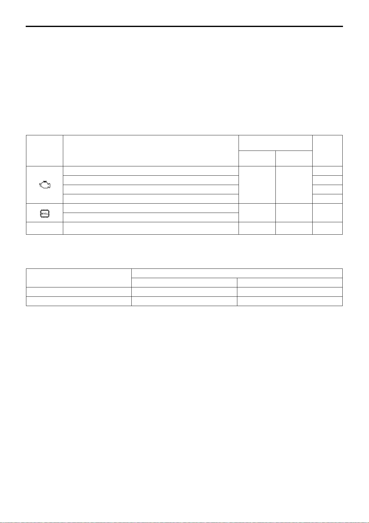
1.1 Systems and diagnosis code displaying methods
1.2 Types of diagnosis codes
• There are two types of diagnosis code output method depending on the system: one has a distinction of present
and past codes, and the other does not have such a distinction.
(1) The system that has a distinction of present and past diagnosis codes
(1.1) Present diagnosis code
• Fault developed in the vehicle after the starter switch is set to ON is indicated by corresponding diagnosis code.
• The fault warning lamp is lit at the same time.
(1.2) Past diagnosis code
• Past fault developed in the vehicle is indicated by corresponding diagnosis code stored in the memory of the elec-
tronic control unit.
• With the vehicle restored to its normal condition or the starter switch turned from OFF to ON after inspection or re-
pair against present diagnosis codes, the present diagnosis code is stored as past diagnosis codes in the memory
of the electronic control unit.
• When reading out the past diagnosis codes, the warning lamp does not illuminate as such codes do not indicate
the current fault.
(2) The system that does not have a distinction of present and past diagnosis codes
• The present and past diagnosis codes are displayed together without distinction.
Warning
lamp
System
Diagnosis codes
displaying methods
Reference
Gr
Multi-Use
Tester
Flashing of
warning lamp
Common rail
OO
13
Turbocharger 15
Exhaust gas recirculation 17
Starter continuous energizing preventing function 54
Vehicle speed limiting (SLD)
OO54
Auto cruise
– Full auto air conditioner O O 55
System
Diagnosis code
With distinction of present and past Without distinction
Except below O –
Full auto air conditioner – O
DIAGNOSIS CODES
00
00-23
2. Reading and Erasing the Diagnosis Code
2.1 Using a Multi-Use Tester
(1) Connecting a Multi-Use Tester
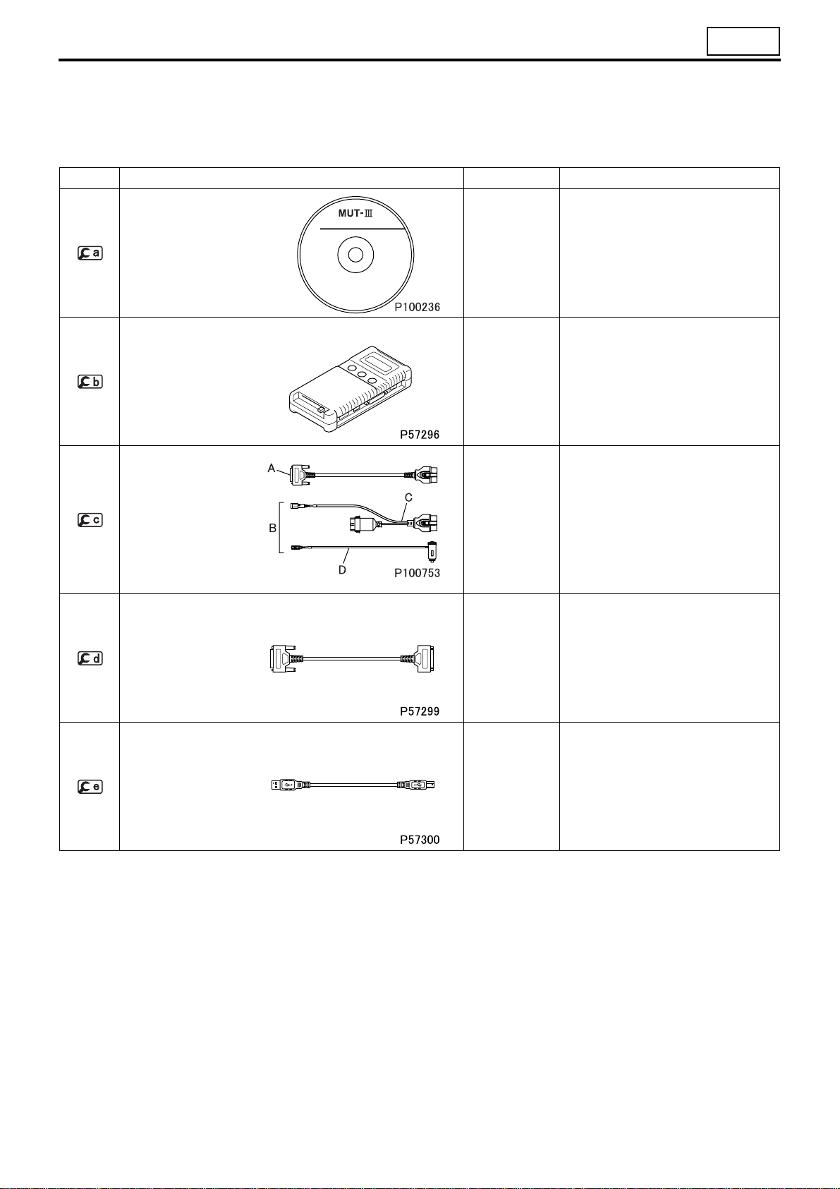
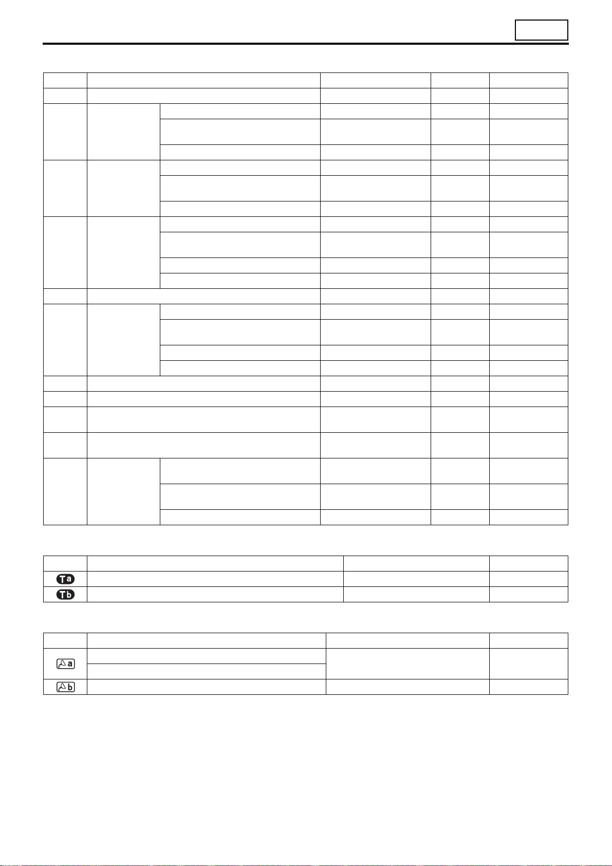
Special tools
Mark Tool name and shape Part No. Application
Multi-Use Tester III
SOFTWARE DISC
FMS-E07-3*
(Multi-Use
Tester-III ver-
sion)
Installation of the Muti-Use-Tester-III
or version-up of the current version
into Multi-Use Tester-III SOFTWARE
DISC (Pub. No. SG0705A)
V.C.I. MH062927
Data transmission between electronic
control unit and PC
Multi-Use Tester test
Harness E
A: Harness for inspec-
tion and drive recorder
B: Harness for drive re-
corder
C: Drive recorder har-
ness
D: Cigarette lighter
plug harness
MH063659
A: MH063661
B: MH063663
C: MH063665
D: MH063666
Power supply to V.C.I. and communi-
cation with electronic control unit
Multi-Use Tester test
harness D
(used for extension)
MH062951
Multi-Use Tester test harness B ex-
tension
USB cable MH063668
Communication between V.C.I. and
PC
SOFTWARE DISC
00-24
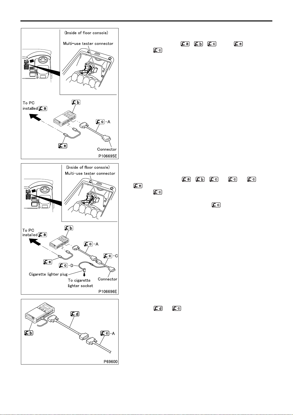
(1.1) To perform system inspection
• Move the starter switch to the LOCK position.
• Connect PC installed , , -A a
nd
as shown.
• Conn
ect
-A connector to the Multi-Use Tester connector on
the vehicle.
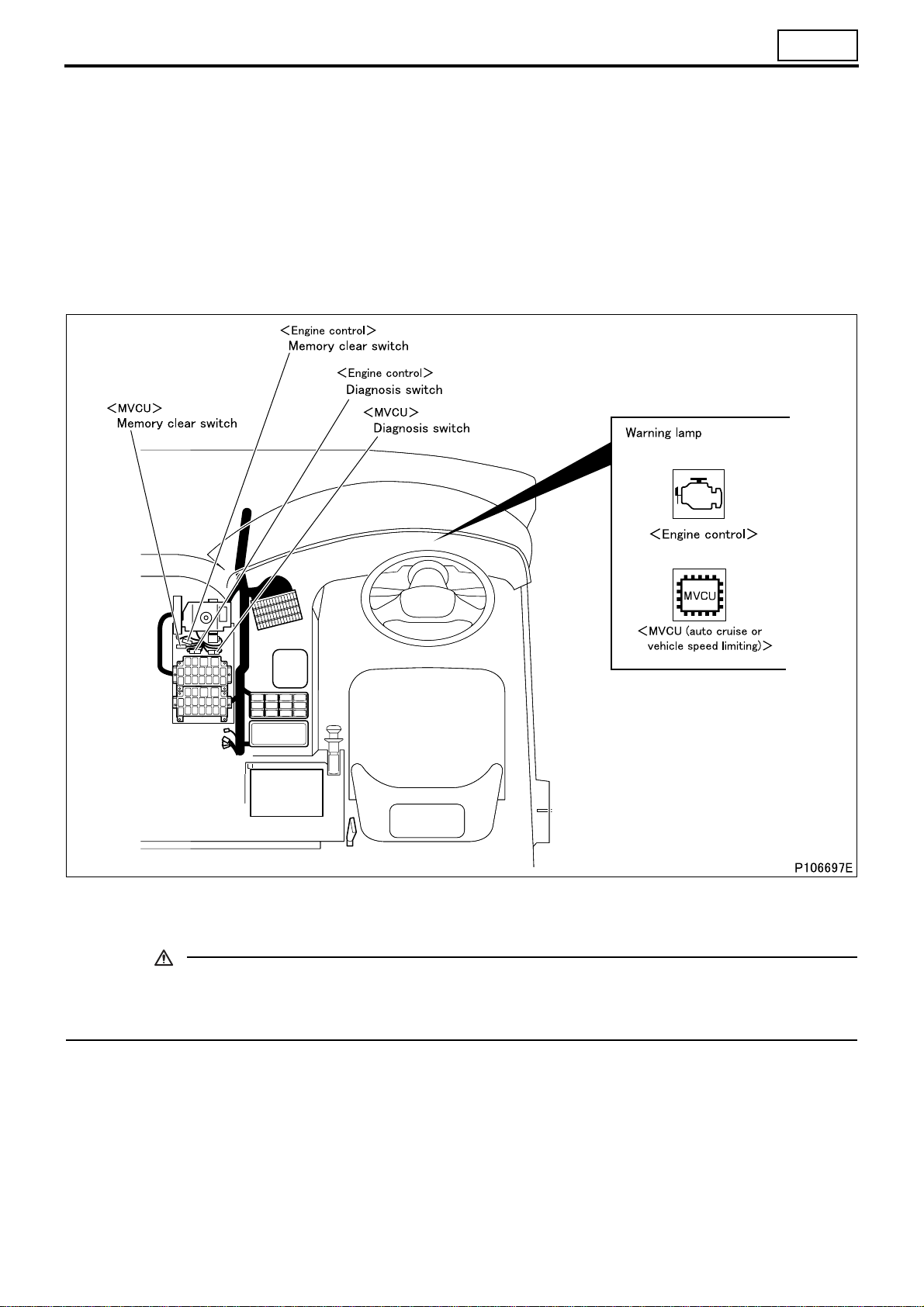
(1.2) To use drive recorder function
• Move the starter switch to the LOCK position.
• Connect PC installed , , -A
, -C,
-D and
as shown.
• Conn
ect
-C connector to the Multi-Use Tester connector on
the vehicle.
• Connect the cigarette lighter plug
of
-D to the cigarette light-
er socket on the vehicle.
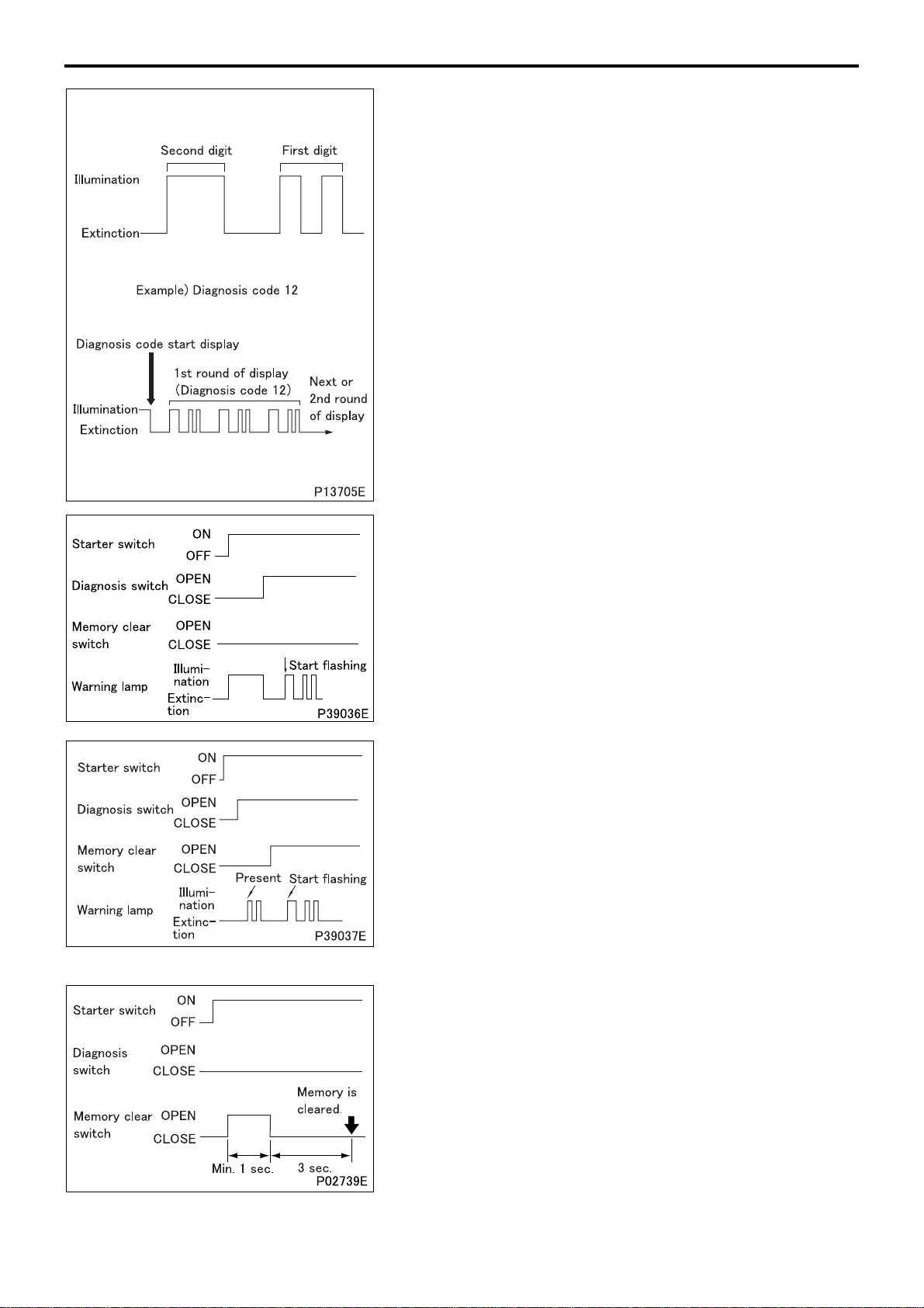
(1.3) To extend the Multi-Use Tester test harness
• Connect to -A to extend the test harness to use the
Multi-Use Tester outside the vehicle.
DIAGNOSIS CODES
00
00-25
(2) Access of diagnosis code
• Set the starter switch to ON.
• Operate the Multi-Use Tester for a display of necessary diagnosis code stored in the memory of the electronic
control unit and identify the location of the fault.
(3) Clearing of diagnosis code
• Set the starter switch to ON (the engine not to be started).
• Operate the Multi-Use Tester to delete all the diagnosis codes stored in the memory of the electronic control unit.
2.2 Using flashing of a warning lamp on meter cluster
(1) Engine control, vehicle speed limiting (SLD), auto cruise
• Using the diagnosis and memory clear switches, display diagnosis codes.
CAUTION
• Opening the memory clear switch followed by its reconnection will erase the stored diagnosis codes from
the memory. To avoid inadvertently erasing necessary codes, be sure to read well the procedure de-
scribed below before handling diagnosis codes.
00-26
(1.1) Reading diagnosis codes
• To read a diagnosis code, observe how may times the warning
lamp flashes and how long each illumination lasts.
• The duration of illumination differs between the first and second
digits.
• Second digit: 1.2 sec.
• First digit: 0.4 sec.
• A diagnosis code consists of the flashing of second digit and the
flashing of first digit in that order. If a diagnosis code has “0” in
the second digit, only the first digit will be displayed.
• The diagnosis code 01 will be displayed if the system is normal.
• The same diagnosis code will be displayed 3 times in a row be-
fore moving to the display of the next code.
• After the last diagnosis code is displayed, the first code will be
displayed again 3 times in a row and then the subsequent
codes. This will be repeated.
(1.2) Present diagnosis codes
• Turn the starter switch ON.
• Remove the diagnosis switch.
• Present diagnosis codes will be displayed by flashing of the
warning lamp.
• When the diagnosis switch is connected, electronic control unit
will stop (terminate) displaying diagnosis codes.
(1.3) Present and past diagnosis codes
• Turn the starter switch to the ON position.
• Open the diagnosis switch.
• Present diagnosis codes will be displayed by flashing of the
warning lamp.
• Open the memory clear switch.
• Present and past diagnosis codes will be displayed by flashing
of the warning lamp.
• Turn the starter switch to the OFF position and connect the
memory clear switch and diagnosis switch to terminate the diag-
nosis code displaying mode.
(1.4) Erasing diagnosis codes
• Turn the starter switch to the ON position (do not start the en-
gine).
• Open the memory clear switch and reconnect it; all diagnosis
codes stored in electronic control unit memory will be erased.
To cancel diagnosis code erasure after opening the memory
clear switch, turn the starter switch to the OFF position and then
reconnect the memory clear switch.
DIAGNOSIS CODES
00
00-27
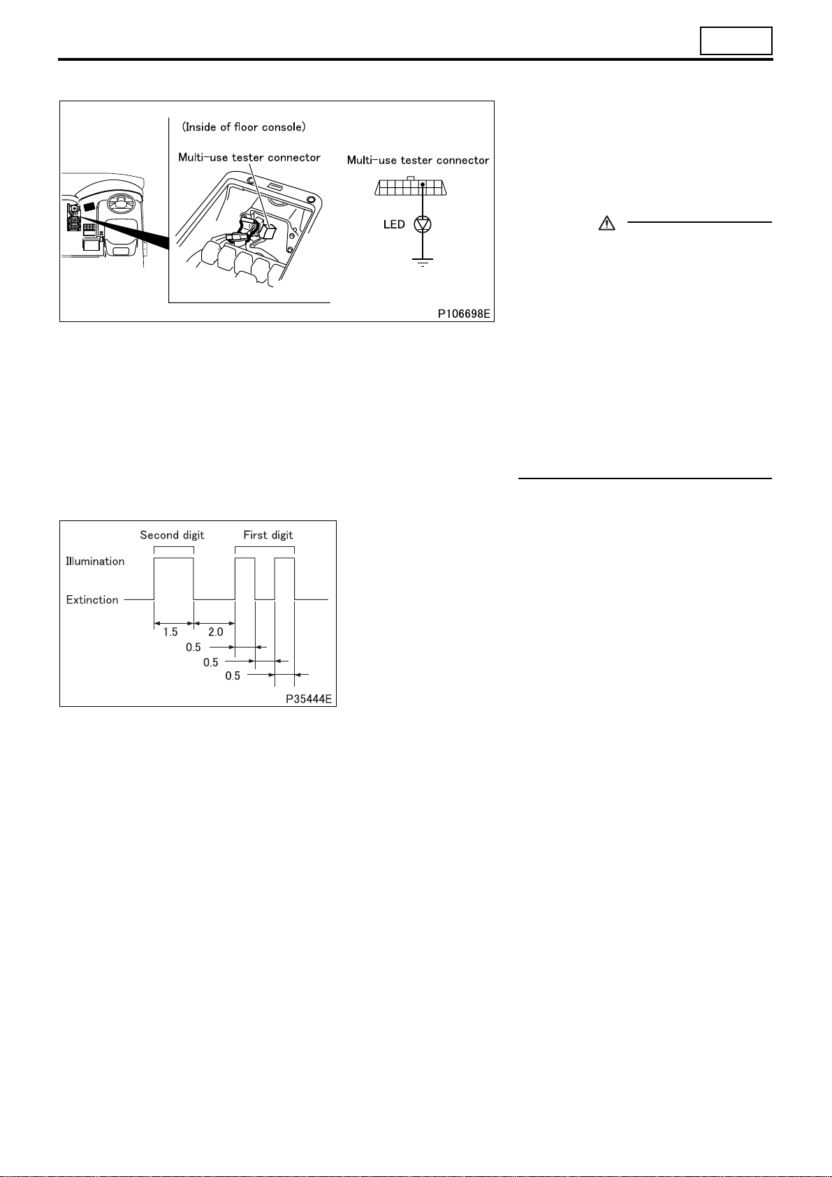
(2) Full automatic air conditioner
(2.1) Connection of LED for inspec-
tion
• Move the starter switch to the LOCK
position.
• Connect the LED for inspection to the
Multi-Use Tester connector.
CAUTION
• Air conditioner electronic control
unit and control panel has a backup
power supply to keep diagnostic
check results in memory. If this
power supply is cut off, with battery
cables disconnected, for example,
stored data are erased.
• Air conditioner electronic control
unit and control panel enters into
the mode of control during fault im-
mediately a fault occurs. In this
mode, control is effected to mini-
mize trouble arising from the fault.
(2.2) Reading and erasing diagnosis codes
• To read a diagnosis code, observe how may times the LED for
inspection flashes and how long each illumination lasts.
• The duration of illumination differs between the first and second
digits.
• Second digit: 1.5 sec.
• First digit: 0.5 sec.
• A diagnosis code consists of the flashing of second digit and the
flashing of first digit in that order. If a diagnosis code has “0” in
the second digit, only the first digit will be displayed.
• When two or more faults occur at a time, relevant diagnosis
codes are displayed repeatedly starting from the first Code.
• To erase a diagnosis code from the memory after inspection,
disconnect negative (–) battery cable and leave it disconnected
for more than 30 seconds.
00-28
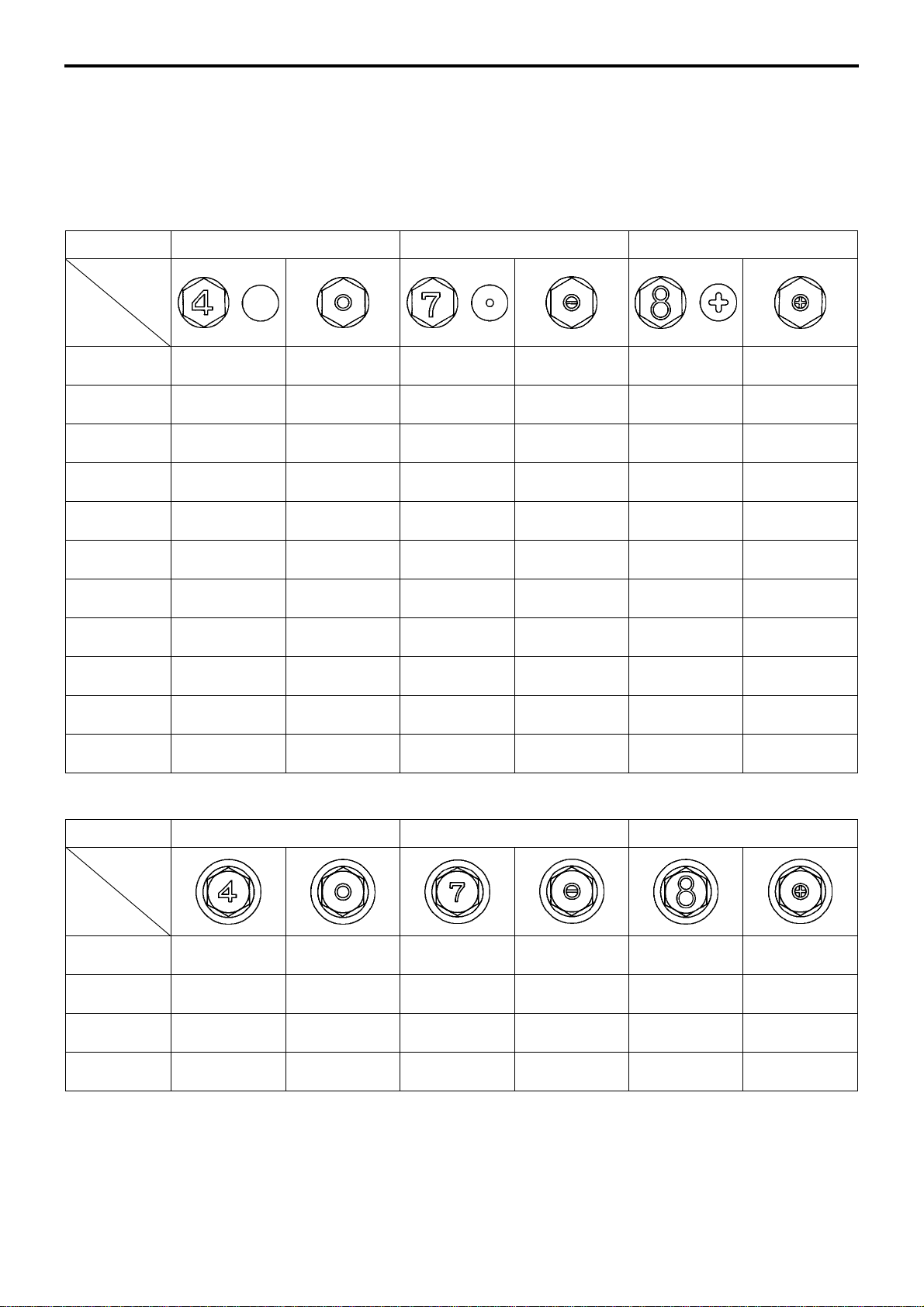
• Use specified bolts and nuts. Tighten them to the torques shown below as appropriate, unless otherwise speci-
fied.
• Threads and bearing surfaces shall be dry.
• If the mating nut and bolt (or stud bolt) are different in level of strength, tighten them to the torque specified for the
bolt.
Hexagon Head Bolts and Stud Bolts (Unit: N·m {kgf·m})
Hexagon Head Flange Bolts (Unit: N·m {kgf·m})
Strength
4T 7T 8T
Identification
symbol
Nominal
diameter (stud) (stud) (stud)
M5
2 to 3
{0.2 to 0.3}
–
4 to 6
{0.4 to 0.6}
–
5 to 7
{0.5 to 0.7}
–
M6
4 to 6
{0.4 to 0.6}
–
7 to 10
{0.7 to 1.0}
–
8 to 12
{0.8 to 1.2}
–
M8
9 to 13
{0.9 to 1.3}
–
16 to 24
{1.7 to 2.5}
–
19 to 28
{2.0 to 2.9}
–
M10
18 to 27
{1.8 to 2.7}
17 to 25
{1.8 to 2.6}
34 to 50
{3.5 to 5.1}
32 to 48
{3.3 to 4.9}
45 to 60
{4.5 to 6.0}
37 to 55
{3.8 to 5.7}
M12
34 to 50
{3.4 to 5.1}
31 to 45
{3.1 to 4.6}
70 to 90
{7.0 to 9.5}
65 to 85
{6.5 to 8.5}
80 to 105
{8.5 to 11}
75 to 95
{7.5 to 10}
M14
60 to 80
{6.0 to 8.0}
55 to 75
{5.5 to 7.5}
110 to 150
{11 to 15}
100 to 140
{11 to 14}
130 to 170
{13 to 17}
120 to 160
{12 to 16}
M16
90 to 120
{9 to 12}
90 to 110
{9 to 11}
170 to 220
{17 to 23}
160 to 210
{16 to 21}
200 to 260
{20 to 27}
190 to 240
{19 to 25}
M18
130 to 170
{14 to 18}
120 to 150
{12 to 16}
250 to 330
{25 to 33}
220 to 290
{23 to 30}
290 to 380
{30 to 39}
250 to 340
{26 to 35}
M20
180 to 240
{19 to 25}
170 to 220
{17 to 22}
340 to 460
{35 to 47}
310 to 410
{32 to 42}
400 to 530
{41 to 55}
360 to 480
{37 to 49}
M22
250 to 330
{25 to 33}
230 to 300
{23 to 30}
460 to 620
{47 to 63}
420 to 560
{43 to 57}
540 to 720
{55 to 73}
490 to 650
{50 to 67}
M24
320 to 430
{33 to 44}
290 to 380
{29 to 39}
600 to 810
{62 to 83}
540 to 720
{55 to 73}
700 to 940
{72 to 96}
620 to 830
{63 to 85}
Strength
4T 7T 8T
Identification
symbol
Nominal
diameter
M6
4 to 6
{0.4 to 0.6}
–
8 to 12
{0.8 to 1.2}
–
10 to 14
{1.0 to 1.4}
–
M8
10 to 15
{1.0 to 1.5}
–
19 to 28
{2.0 to 2.9}
–
22 to 33
{2.3 to 3.3}
–
M10
21 to 31
{2.1 to 3.1}
20 to 29
{2.0 to 3.0}
45 to 55
{4.5 to 5.5}
37 to 54
{3.8 to 5.6}
50 to 65
{5.0 to 6.5}
50 to 60
{5.0 to 6.5}
M12
38 to 56
{3.8 to 5.5}
35 to 51
{3.5 to 5.2}
80 to 105
{8.0 to 10.5}
70 to 95
{7.5 to 9.5}
90 to 120
{9 to 12}
85 to 110
{8.5 to 11}
TABLE OF STANDARD TIGHTENING TORQUES
00
00-29
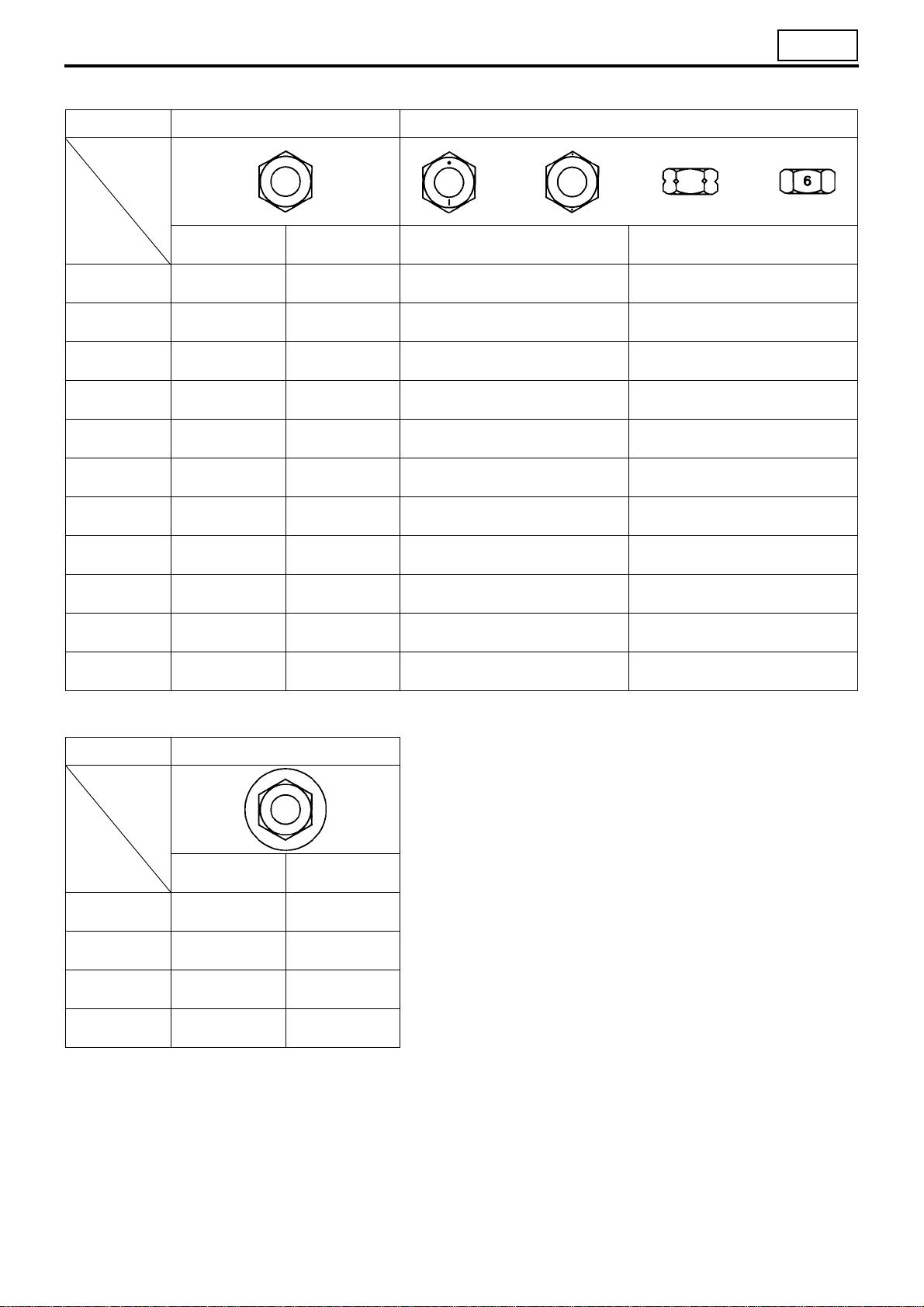
Hexagon Nuts (Unit: N·m {kgf·m})
Hexagon Flange Nuts (Unit: N·m {kgf·m})
Strength
4T 6T
Identification
symbol
Nominal
diameter
Standard screw
thread
Coarse screw
thread
Standard screw thread Coarse screw thread
M5
2 to 3
{0.2 to 0.3}
–
4 to 6
{0.4 to 0.6}
–
M6
4 to 6
{0.4 to 0.6}
–
7 to 10
{0.7 to 1.0}
–
M8
9 to 13
{0.9 to 1.3}
–
16 to 24
{1.7 to 2.5}
–
M10
18 to 27
{1.8 to 2.7}
17 to 25
{1.8 to 2.6}
34 to 50
{3.5 to 5.1}
32 to 48
{3.3 to 4.9}
M12
34 to 50
{3.4 to 5.1}
31 to 45
{3.1 to 4.6}
70 to 90
{7.0 to 9.5}
65 to 85
{6.5 to 8.5}
M14
60 to 80
{6.0 to 8.0}
55 to 75
{5.5 to 7.5}
110 to 150
{11 to 15}
100 to 140
{11 to 14}
M16
90 to 120
{9 to 12}
90 to 110
{9 to 11}
170 to 220
{17 to 23}
160 to 210
{16 to 21}
M18
130 to 170
{14 to 18}
120 to 150
{12 to 16}
250 to 330
{25 to 33}
220 to 290
{23 to 30}
M20
180 to 240
{19 to 25}
170 to 220
{17 to 22}
340 to 460
{35 to 47}
310 to 410
{32 to 42}
M22
250 to 330
{25 to 33}
230 to 300
{23 to 30}
460 to 620
{47 to 63}
420 to 560
{43 to 57}
M24
320 to 430
{33 to 44}
290 to 380
{29 to 39}
600 to 810
{62 to 83}
540 to 720
{55 to 73}
Strength
4T
Identification
symbol
Nominal
diameter
Standard screw
thread
Coarse screw
thread
M6
4 to 6
{0.4 to 0.6}
–
M8
10 to 15
{1.0 to 1.5}
–
M10
21 to 31
{2.1 to 3.1}
20 to 29
{2.0 to 3.0}
M12
38 to 56
{3.8 to 5.6}
35 to 51
{3.5 to 5.2}

00-30
Tightening Torque for General-Purpose Flare Nut (Unit: N·m {kgf·m})
Tightening Torque for General-Purpose Air Piping Nylon Tube (DIN Type) (Unit: N·m
{kgf·m})
Tightening Torque for General-Purpose Air Piping Nylon Tube (SAE Type) (Unit: N·m
{kgf·m})
Pipe diameter φ4.76 mm φ6.35 mm φ8 mm φ10 mm φ12 mm φ15 mm
Tightening torque 17 {1.7} 25 {2.6} 39 {4.0} 59 {6.0} 88 {9.0} 98 {10}
Nominal diameter
× wall thickness
6 × 1 mm 10 × 1.25 mm 12 × 1.5 mm 15 × 1.5 mm
Tightening torque 20 {2.0 } 34 {3.5 } 49 {5.0 } 54 {5.5 }
Nominal diameter 1/4 in. 3/8 in. 1/2 in. 5/8 in.
Tightening torque 13 {1.3 } 29 {3.0 } 49 {5.0 } 64 {6.5 }
+6
0
+0.6
0
+10
0
+1.0
0
+10
0
+1.0
0
+5
0
+0.5
0
+4
0
+0.4
0
+5
0
+0.5
0
+5
0
+0.5
0
+5
0
+0.5
0
TABLE OF STANDARD TIGHTENING TORQUES

11-1
GROUP 11 ENGINE
SPECIFICATIONS .............................................................................. 11-2
STRUCTURE AND OPERATION
1. Engine Proper .................................................................................... 11-3
2. Rocker and Shaft, Camshaft, Rocker Case and
Cyl
inder Head Gasket .......................................................................
11-4
3. Valve Mechanism ............................................................................... 11-4
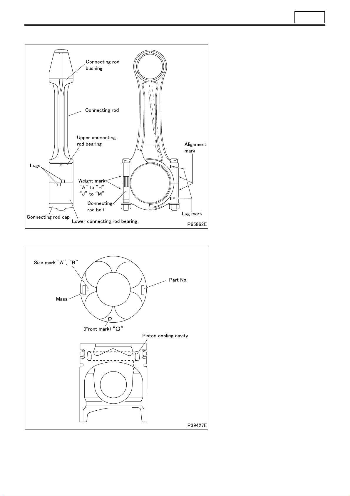
4. Connecting Rod ................................................................................. 11-5
5. Piston .................................................................................................. 11-5
6. Timing Gears ...................................................................................... 11-6
7. Flywheel ............................................................................................. 11-6
8. Flywheel PTO ..................................................................................... 11-7
9. Powertard Brake System .................................................................. 11-8
TROUBLESHOOTING ..................................................................... 11-12
ON-VEHICLE INSPECTION AND ADJUSTMENT
1. Measuring Compression Pressure ................................................ 11-14
2. Inspection and Adjustment of Valve Clearances .......................... 11-16
3. Inspection and Adjustment of Powertard Clearances ................. 11-20
ENGINE REMOVAL AND INSTALLATION ...................................... 11-22
ROCKER COVER, ROCKER AND SHAFT ..................................... 11-26
CAMSHAFT AND ROCKER CASE ................................................. 11-30
CYLINDER HEAD AND VALVE MECHANISM ................................ 11-38
PISTON, CONNECTING ROD AND CYLINDER LINER ................. 11-54
FLYWHEEL PTO <WITH FLYWHEEL PTO> ................................... 11-68
FLYWHEEL ...................................................................................... 11-72
TIMING GEARS
<WITHOUT FLYWHEEL PTO>...................................................... 11-78
<WITH FLYWHEEL PTO> ............................................................ 11-82
CRANKSHAFT AND CRANKCASE ................................................. 11-88

11-2
Item Specifications
Engine type 6M70T2 6M70T4
Type 6-cylinder, in-line, water-cooled, 4-cycle diesel engine
Combustion chamber Direct injection type
Valve mechanism Overhead camshaft (OHC) system
Maximum output kW {PS} /rpm 257 {350} / 2000 309 {420} / 2000
Maximum torque N·m {kgf·m} /rpm 1620 {165} / 1100 1810 {185} / 1100
Cylinder bore × stroke mm φ135 × 150
Total displacement cm
3
{L} 12882 {12.882}
Compression ratio 17.5
SPECIFICATIONS
Mitsubishi 6M70 Engine Parts contact:
email: [email protected]
Phone: 269 673 1638
11
11-3
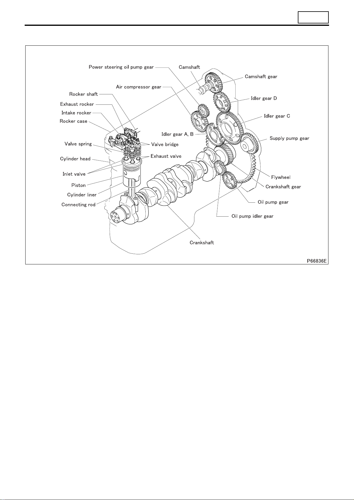
1. Mitsubishi 6M70 Engine Proper
• The 6M70 engine employs an overhead camshaft (OHC) system, with the valve mec
hanism and the timing
gears arranged as shown above.
STRUCTURE AND OPERATION
11-4
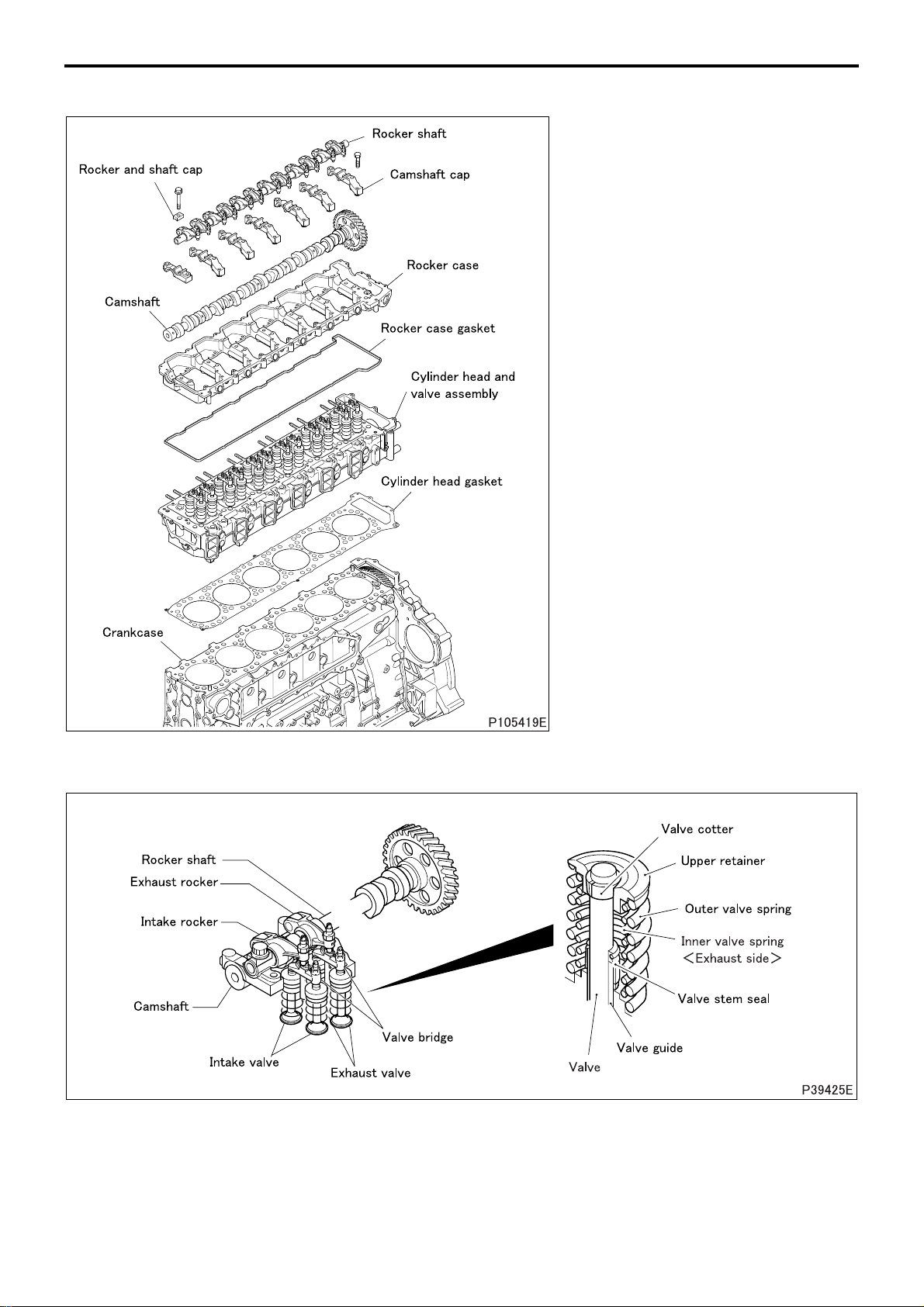
2. Rocker and Shaft, Camshaft, Rocker Case and Cylinder Head Gasket
• The camshaft journals are directly
supported by the rocker case and the
camshaft cap, without using any cam-
shaft bearings. The rocker case and
camshaft caps have been machined
together, meaning that they all need to
be replaced for a new set when one of
them becomes defective.
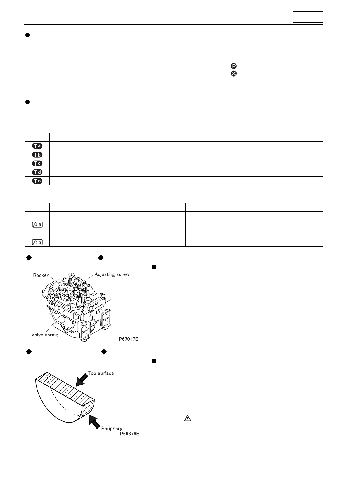
3. Valve Mechanism
• Each valve has a valve stem seal, which regulates the flow of lubricating oil to the contact surface between the
valve and the valve guide.
• The valve springs have a variable pitch to prevent abnormal vibration at high engine speed. The exhaust valves
use a double spring, with the inner and outer springs coiled in different directions to prevent them from jamming
each other.
STRUCTURE AND OPERATION
11
11-5
4. Mitsubishi 6M60 Connecting Rod
• Weight mark: “A” to “H”, “J” to “M”
• “A” indicates the greatest connecting
rod mass.
5. Mitsubishi 6M70 Piston
11-6
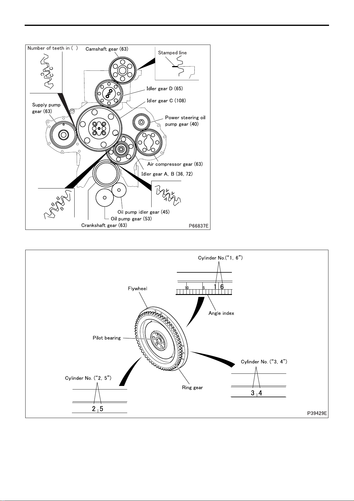
6. Mitsubishi 6M70 Timing Gears
• The timing gears are provided with
timing marks to help ensure correct
assembly.
• Timing marks are provided on the fol-
lowing gears.
• Camshaft gear: stamped line
• Crankshaft gear: “A”
• Idler gear A, B: “A”, “B”
• Idler gear C: “B”, “C”
• Supply pump gear: “C”
7. Flywheel
STRUCTURE AND OPERATION
11
11-7
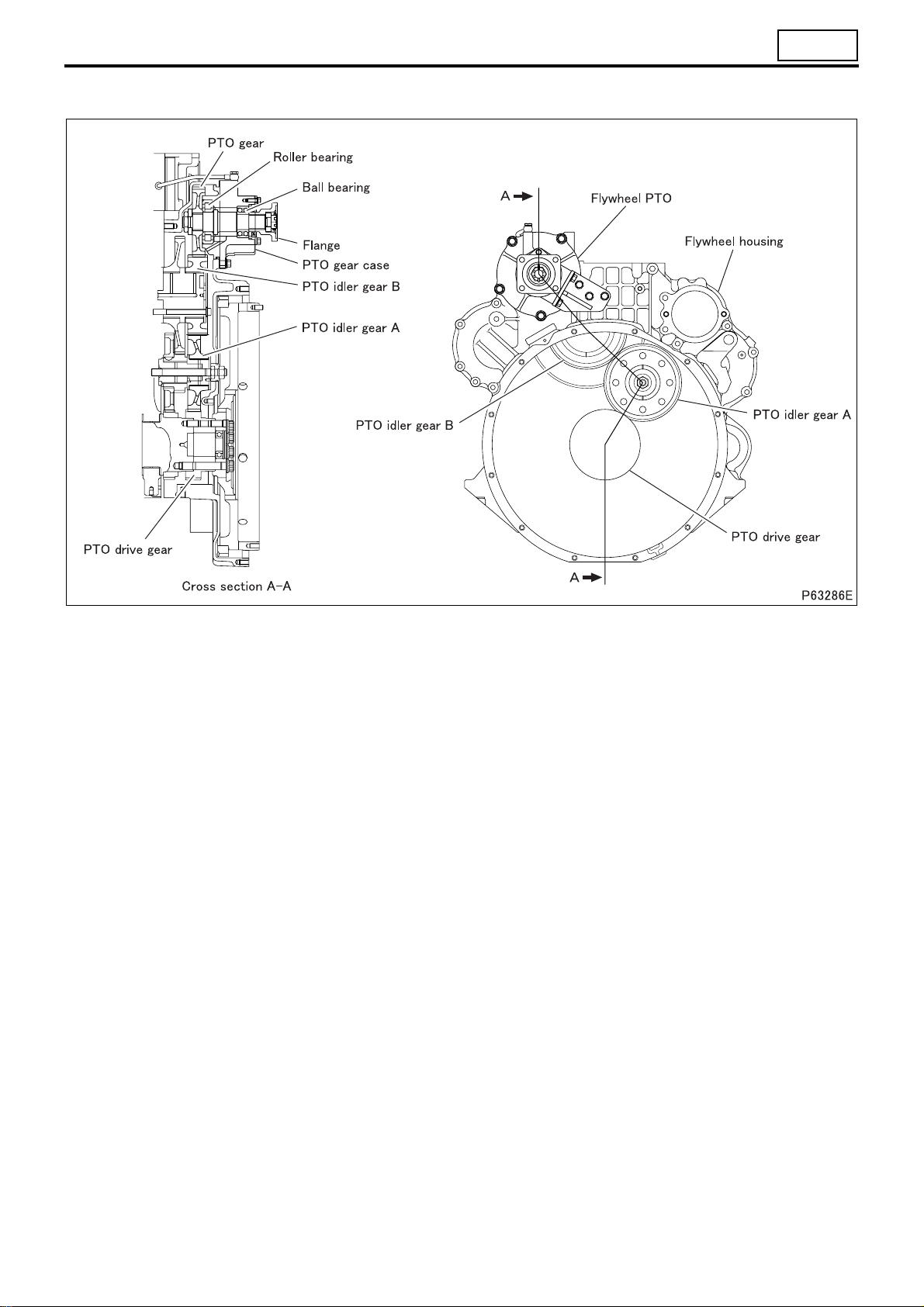
8. Flywheel PTO
• The flywheel PTO is located in the upper part of the flywheel housing and is driven by the PTO drive gear.
11-8
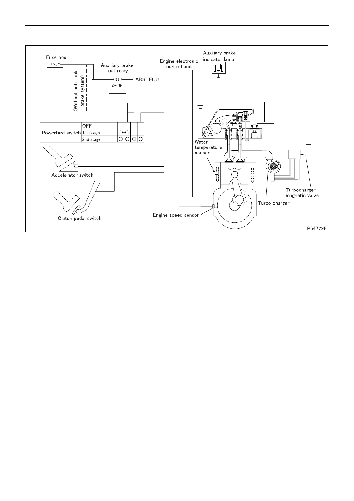
9. Powertard Brake System
• The Powertard is activated when all of the following conditions are met with the combination switch placed in the
first stage or second stage.
• Engine speed: 800 to 2400 rpm
• Clutch pedal released (clutch pedal switch: OFF)
• Accelerator pedal released (accelerator pedal switch: ON)
• Transmission in gear (transmission neutral switch: ON)
• Anti-lock brake system not activated (ABS) (Control unit: OFF) (See Gr35E.)
• If any of the above conditions are not met, operation of the Powertard system will be temporarily canceled.
If the engine speed is less than 700 rpm or higher than 2500 rpm although all the other conditions (clutch pedal,
accelerator pedal, and transmission conditions) are met, operation of the Powertard system will be canceled.
• When the vehicle speed exceeds the auto cruise set vehicle speed during driving with the auto cruise engaged,
the Powertard is activated by the control of the engine electronic control unit even if the Powertard switch (combi-
nation switch) is not turned ON. (See Gr13.)
• When the Powertard switch is placed in the first stage, the Powertard is activated to enhance the engine braking
power.
• When the Powertard switch is placed in the second stage, the turbocharger magnetic valve is activated to control
the turbocharger and generate stronger braking power than the first stage.
STRUCTURE AND OPERATION
11
11-9
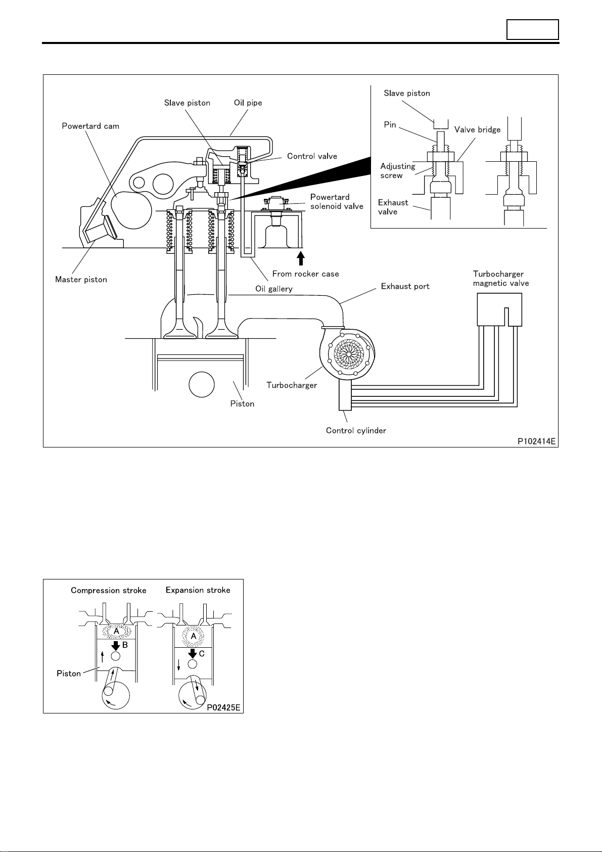
9.1 Operation of Powertard brake system
• The Powertard brake system is a device to enhance the engine brake performance. It opens and closes the ex-
haust valve (one side only) to control the volume of compressed air in the combustion chamber in accordance
with the movement of the piston, thereby providing a boosted braking force. Powertard components are located in
the cylinder head.
• The valve bridge is provided with an adjusting screw and a pin that allow the exhaust valve to be opened and
closed under the control of the Powertard, in addition to ordinary valve control.
• The pin is free to move in the adjusting screw. Its movement is controlled by the control valve.
• The adjusting screw is used to adjust the timing (Powertard clearance) for the control valve to press the pin.
(1) Operating principle
• In the ordinary engine brake, the piston is forced up during its
compression stroke when compressed air A develops a counter
force B to press the piston. This force works as a braking force.
However, the piston is forced down during its expansion stroke
to let compressed air expand. This causes an accelerating force
C to work on the piston downward, resulting in the braking force
obtained during the compression period being lost largely.
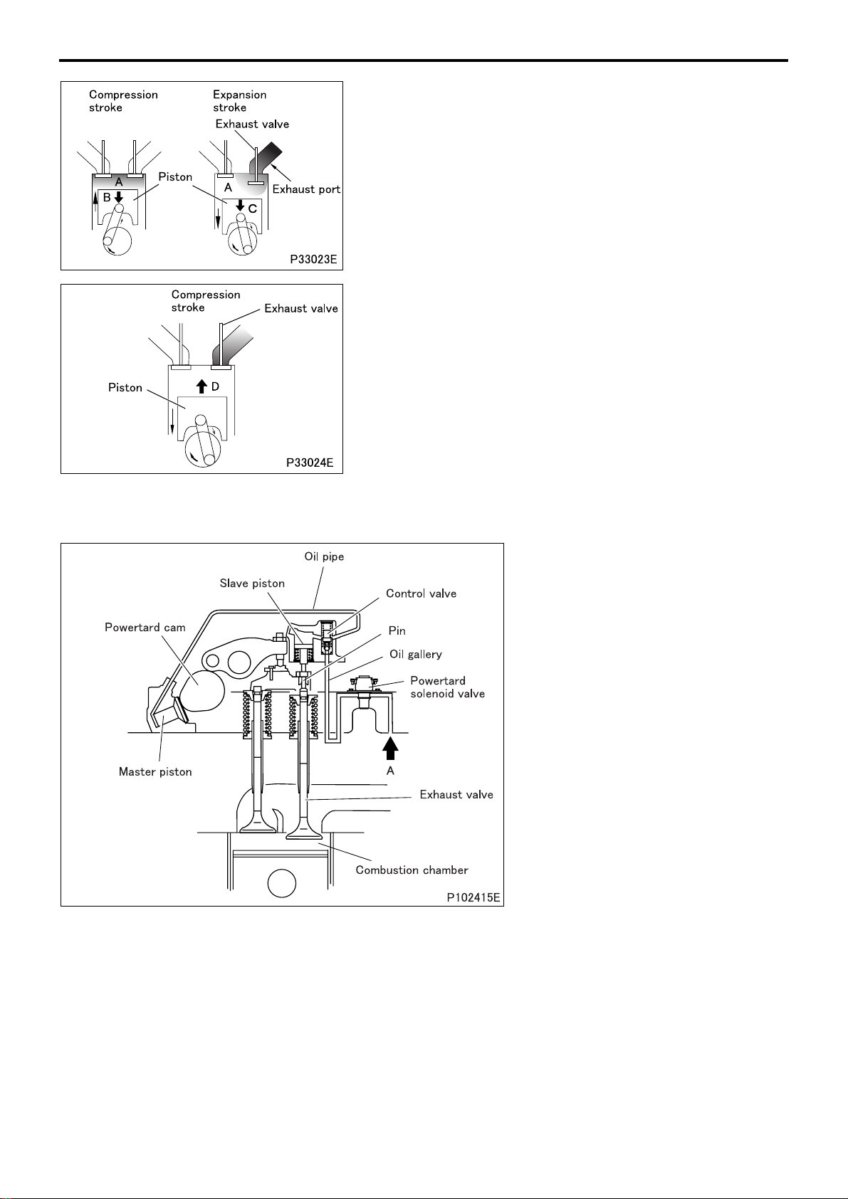
11-10
• When the Powertard system is activated, the piston pressing
force works as a braking force during the compression stroke as
when the Powertard system is not activated. During the expan-
sion period, the exhaust valve is opened by the working of the
system to let some of the compressed air out through the ex-
haust po
rt.
• Thi
s causes the piston pressing force to be no longer generated.
As a result, the braking force obtained during the compression
period is maintained for effective use.
• After letting out more compressed air, the exhaust valve is
closed, which causes the combustion chamber to be closed up.
As a result, during the expansion period, a new force is generat-
ed which hinders the movement of piston when it goes down.
This force, following the braking force obtained during the previ-
ous compression period, also acts as a braking force, enhancing
greatly the vehicle’s engine brake capacity
.
The
operation of the system which causes the valve to be
opened and closed in agreement with the successive piston
strokes is called synchronized operation.
• As shown above, when the Powertard system is activated, the
engine brake provides more power than the ordinary engine
brake.
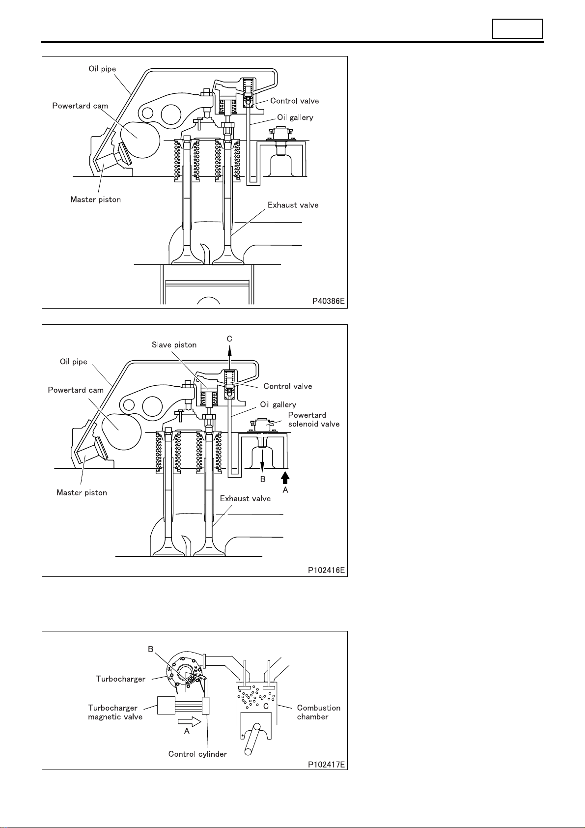
(2) Hydraulic pressure control
• When the solenoid valve is activated,
engine oil (oil pressure produced by
ordinary engine oil pump) is let in from
A to flow through the oil passage and
forces open the check valve in the
control valve.
• Oil pressure proceeds through the oil
passage to move the master piston
into contact with the dedicated Power-
tard cam.
• This allows the rotation of the dedicat-
ed Powertard cam to be transmitted to
the master piston. As the cam lobe top
is reached, oil pressure in the oil pas-
sage further builds up, forcing the
check valve in the control valve to
close and working on the slave piston
at the same time.
• The slave piston pushes the pin, which
in turn forces the exhaust valve to
open. As a result, the pressure in the
combustion chamber is released to
maintain effective braking force.
STRUCTURE AND OPERATION
11
11-11
• As the Powertard cam further rotates
and the cam lobe top leaves the mas-
ter piston, the oil pressure in the oil
passage is reduced.
• As a result, the exhaust valve is
closed by its spring force, which allows
the valve to open and close according
to ordinary valve timing. At the same
time, the check valve in the control
valve opens to let engine oil (oil pres-
sure produced by ordinary engine oil
pump) work through the oil passages
and, allowing the exhaust valve to be
forced open again through the move-
ment of the Powertard cam.
• When the Powertard release condi-
tions are met, the following sequence
of operation is followed.
• When the solenoid valve is de-ener-
gized, the control valve shuts the in-
coming path (A) for engine oil from
the rocker case and opens the out-
going path (B) to the cylinder head.
• Engine oil in the oil passage is let
out through B, relieving the control
valve of oil pressure.
• The control valve opens the path
(C)
th
at has been closed by oil pres-
sure to let out engine oil in the
chamber of the slave piston and oil
passage.
• As the oil pressure is removed, the
master piston is lowered to leave
the Powertard cam.
• At the same time, the slave piston is
forced up by the spring force. As a
result, the exhaust valve is closed
and the Powertard is turned off.
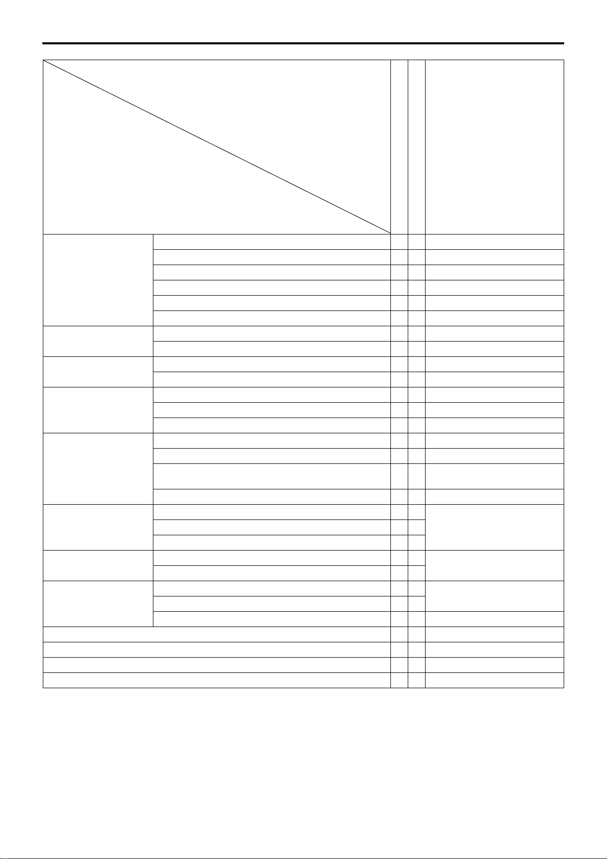
(3) Powertard brake control (Power-
tard: Switch is placed in the sec-
ond stage)
• The turbocharger magnetic valve
feeds air A to the air cylinder, narrow-
ing turbine vane B.
• The number of revolutions of the tur-
bocharger increases, taking more air
into the combustion chamber.
• Compressed air C increases and the
braking force of the Powertard be-
comes stronger.
11-12
Symptoms
Low power output
Abnormal engine noise
Reference Gr
Possible causes
Cylinder head and valve
mechanism
Valve clearance incorrect O O
Defective cylinder head gasket O O
Valve and valve seat worn and carbon deposits O O
Valve spring fatigued O O
Defective rocker shaft and bracket O
Poor lubrication of rocker shaft and bracket assembly O
Timing gears
Defective backlash between gears O
Poor lubrication of gearts and idler shaft O
Camshaft
Camshaft end play excessive O
Camshaft worn O
Pistons and connecting
rods
Piston ring groove(s) worn and damaged O O
Piston ring(s) worn and damaged O O
Piston pin and connecting rod small end worn O
Crankshaft
Crankshaft end play excessive O
Fan pulley improperly mounted O
Crankshaft pins and connecting rod bearings worn or
damaged
O
Crankshaft journals and main bearings worn or damaged O
Fuel system
Defective supply pump O O
Gr13Defective injector O O
Air trapped in fuel system O
Cooling system
Cooling system malfunction O
Gr14
Belts loose/damaged O
Intake and exhaust
system
Air cleaner colgged O O
Gr15
Turbocharger malfunction O O
Diesel particulate filter colgged O O Gr15
Oil viscosity unsuitable O Gr12
Improper fuel O
Incorrectly fitted piping and hoses O
Defective/incorrectly fitted alternator and other auxiliaries O Gr54
TROUBLESHOOTING
11
11-13
Powertard Brake System
Symptoms
Powertard brake fails to operate
Turning Powertard switch OFF does not
cancel Powertard braking
Reference Gr
Possible causes
Lubrication oil is cold and too viscous O O
Powertard clearance too large O
Electrical system
Blown fuse O
Gr13
Improper connection of harnesses and connectors O
Defective clutch switch O O
Defective accelerator switch O O
Defective transmission neutral switch O O
Defective powertard switch (combination switch) O O
Defective meter cluster O O
Defective engine speed sensor O O
Defective powertard solenoid valve O O
Defective engine control unit O O
Defective ABS exhaust brake cut relay <ABS/ASR> O O Gr35
Defective Powertard O O
Valve mechanism
Broken or weak exhaust valve springs O
Exhaust valve sticky or not smooth in operation O
Improperly adjusted powertard clearance O
Oil leakage in Powertard system O
Engine oil pressure too low O
Insufficient engine oil flow
Air present in engine oil O
Oil leakage from around cylinder head and rocker case O
Oil passage leading to powertard assembly clogged O
Oil leakage from powertard brake system O
Gr12
Defective control valve O
11-14
1. Measuring Compression Pressure
Service standards
Special tools (Unit: mm)
• A drop in compression pressure can be used as a guide to determine when the engine should be overhauled.
• Measure the compression pressure at regular intervals. Keeping track of its transitions can provide a useful tool
for troubleshooting. On new vehicles and vehicles with newly replaced parts, the compression pressure will be
somewhat higher depending on the break-in condition of piston rings, valve seats, etc., but this will return to nor-
mal as the parts wear down.
• Before the compression measurement, confirm that the engine oil, starter, and battery are in normal condition.
• Place the vehicle in the following cond
itions.
• Warm up the engine until the coolant temperature reaches approximately 75 to 85°C.
• Turn off the lights and accessories.
• Place the transmission in N range.
• Turn the steering wheel in neutral position.
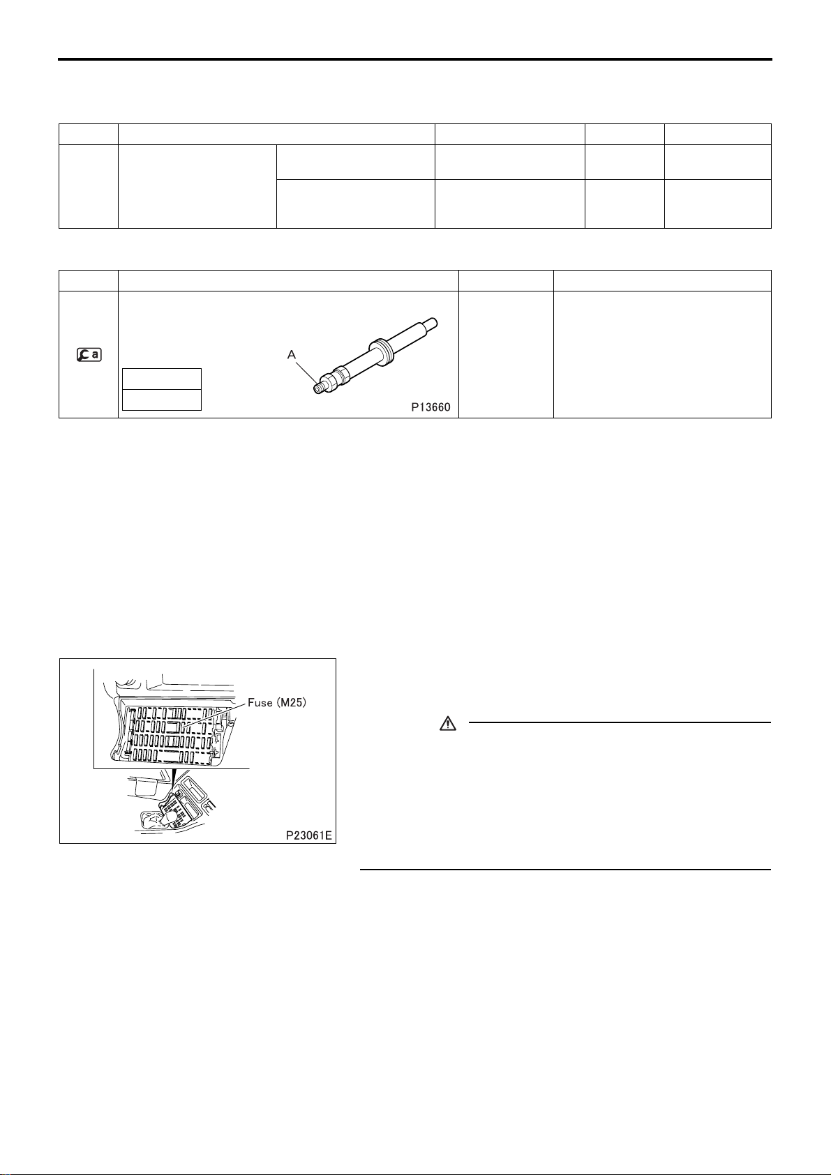
• Remove the fuse (M25) from the fuse box in the cab to prevent
fuel from being injected while the engine is cranked using the
starter.
CAUTION
• When cranking the engine, never shut off the power sup-
plied to the engine electronic control unit by disconnecting
the engine electronic control unit connector or other similar
methods. If the engine is cranked with the power to the en-
gine electronic control unit shut off, the supply pump will
not be controlled by the electronic control unit, causing the
supply pump to be malfunctioned.
Location Maintenance item Standard value Limit Remedy
–
Mitsubishi 6M70
Compression press
ure
Each cylinder (at 200 rpm)
2,940 kPa
{30 kgf/cm
2
}
1,960 kPa
{20 kgf/cm
2
}
Inspect
Pressure difference be-
tween each cylinder
–
390 kPa
{4 kgf/cm
2
}
or less
Inspect
Mark Tool name and shape Part No. Application
MH062180 Measuring of compression pressure
Compression gauge
adapter
A
M14 × 1.5
ON-VEHICLE INSPECTION AND ADJUSTMENT
11
11-15
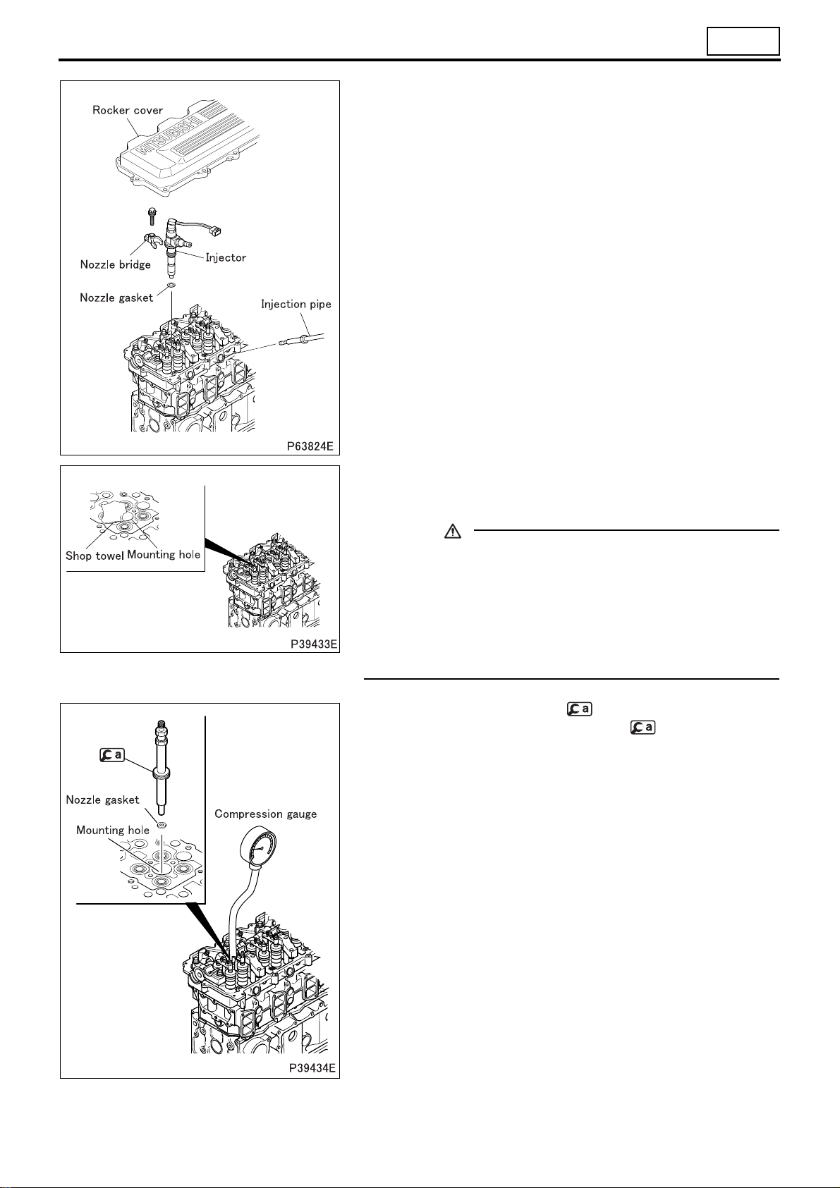
• Remove all the injectors. (See Gr13.)
• Cover the injector mounting holes with shop towels or other sim-
ilar cloth. Crank the engine using the starter. Ensure that no for-
eign matter is attached on the shop towels.
CAUTION
• If cracks or any other damage are evident in the cylinders,
this means that the coolant, engine oil or fuel, or other sub-
stances, has entered the cylinders. If this is the case, it is
extremely dangerous to crank the engine as these sub-
stances will gush out at high temperature from the injector
mounting holes. Stay away from the engine when cranking
it.
• Attach the nozzle gasket and to one of the mounting holes.
Then, connect a compression gauge to .
• Crank the engine and measure the compression pressure.
• Measure the compression pressure for all the cylinders one after
another. Determine the compression pressure difference be-
tween the cylinders.
• If the compression pressure is below the limit or the pressure dif-
ference between each cylinder is not within the limit, pour a
small amount of engine oil into the corresponding mounting hole
and measure the compression pressure again.
• If the compression pressure increases, the piston rings and
inner surfaces of cylinder may be badly worn or otherwise
damaged.
• If the compression pressure remains unchanged, there may
be seizure in the valves, the valves may be incorrectly seated
or the cylinder head gasket may be defective.
• Install the injector. (See Gr13.)
• Install the rocker cover and the gasket. (See “ROCKER COV-
ER, ROCKER AND SHAFT”.)
11-16
2. Mitsubishi 6M70 Inspection and Adjustment of
Valve Clearances Service standards (Unit
:
mm)
Tightening torque (Unit: N·m {kgf·m})
• Mitsubishi 6M70 Valve c
learances should be checked and
adjusted as follows while the engine is still cold.
[Inspection]
• Remove the rocker cover.
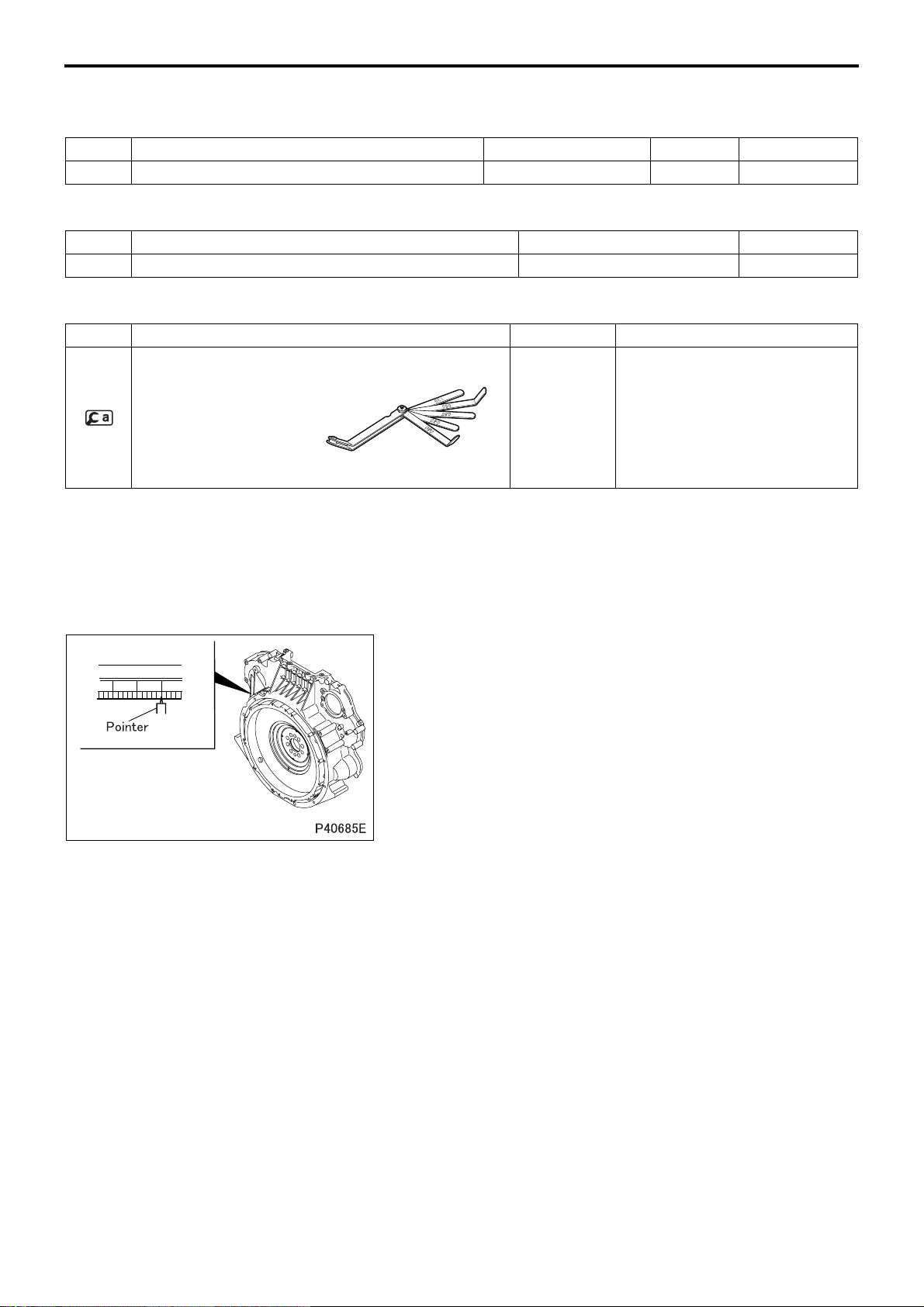
• Bring the No. 1 or No. 6 cylinder piston to the top dead center
(TDC) on the compression stroke according to the following pro-
cedure:
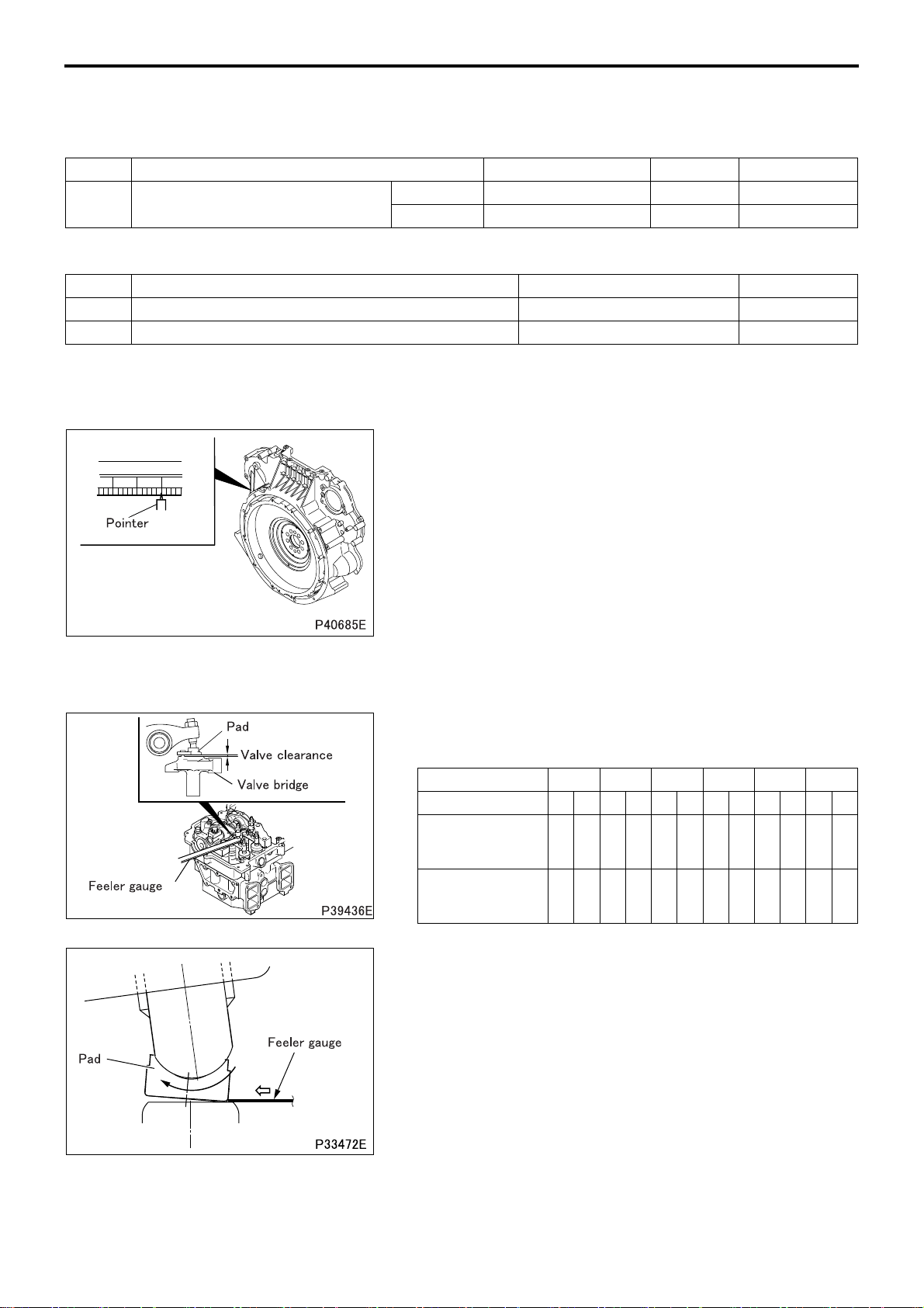
• Crank the engine until the pointer is aligned with the “1 6”
mark on the flywheel.
• This will place either the No. 1 or No. 6 cylinder piston at TDC
on the compression stroke. The cylinder in which the rocker
arms for both the intake and exhaust valves can be pushed
down by hand by the valve clearance amounts has its piston
at TDC. Rotate the engine by one full turn to switch the TDCs
of the No. 1 and No. 6 cylinder piston
s.
• With
the No. 1 or No. 6 cylinder piston at TDC, measure the
clearance of the valves (clearance between valve bridge and
pad) marked with a circle in the table below.
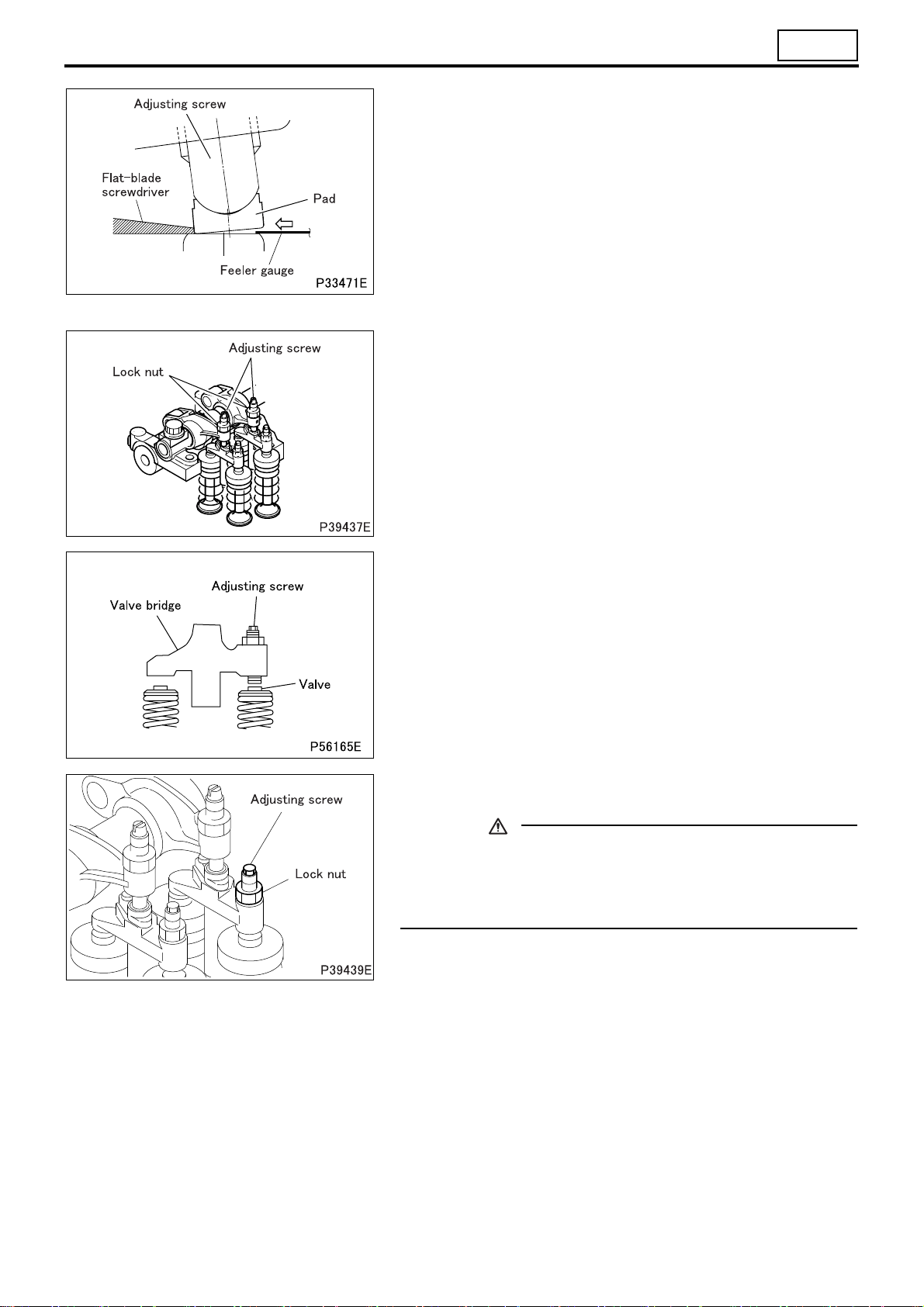
• Any attempt to insert a feeler gauge without first securing suffi-
cient space, as described above, between the pad and the valve
bridge will fail, as the pad will tilt as shown in the illustration, thus
blocking the entry of a feeler gauge.
Location Maintenance item Standard value Limit Remedy
–
Mitsubishi 6M70
Valve clearance (
when engine is cold)
Intake side 0.4 – Adjust
Exhaust side 0.6 – Adjust
Mark Parts to be tightened Tightening torque Remarks
–
Loc
k nut ( 6M70 valve bridge adjusting screw tightening) 68 {7} –
–
Lock nut ( 6M
70 rocker arm adjusting screw tightening) 60 {6} –
Cylinder No. 123456
Valve INEXINEXINEXINEXINEXINEX
No. 1 cylinder
piston at TDC on
compression stroke
OOO––OO– –O– –
No. 6 cylinder
piston at TDC on
compression stroke
–––OO––OO–OO
5
10
1
6
ON-VEHICLE INSPECTION AND ADJUSTMENT
11
11-17
• Before inserting a feeler gauge, push the adjusting screw pad on
the side opposite from where a feeler gauge is to be inserted, as
shown in the illustration, using a flat-blade screwdriver or other
similar tool. This will create space necessary for the gauge to be
inserted.
• The measurement is correct when the feeler gauge feels slightly
resisted as it is inserted.
• The measurement is not yet correct if the feeler gauge can still
be inserted smoothly.
• If the measurement deviates from the standard value, adjust as
follows.
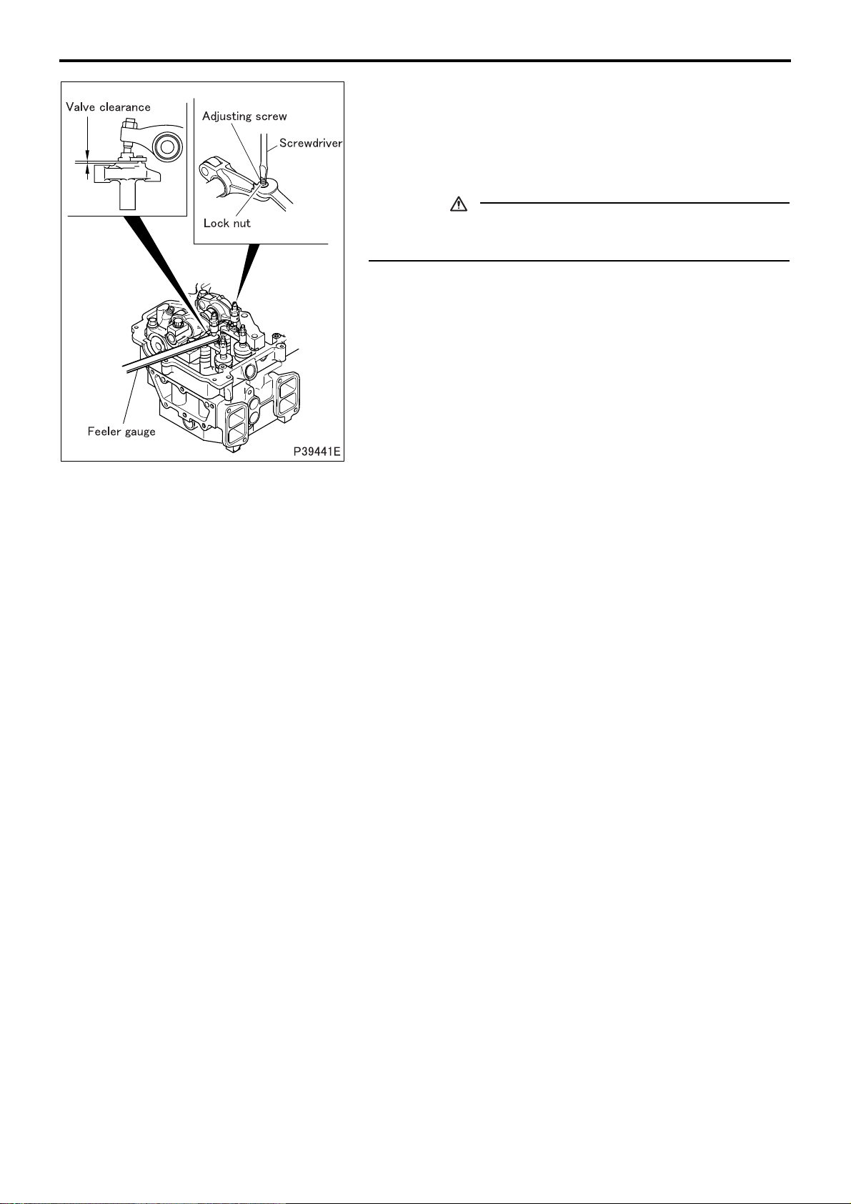
[Adjustment]
• Loosen the lock nuts and adjusting screws on the valve bridge
and rocker arm.
• While holding the valve bridge by hand, screw in the adjusting
screw until it lightly contacts the valve stem end.
• Then, further screw in the adjusting screw by 45°.
• While holding the adjusting screw in this position, tighten the
lock nuts to the specified torque.
CAUTION
• After adjusting the adjusting screw, be sure to tighten the
lock nut to the specified torque. Insufficient torquing will
compromise the parallelism of the valve bridge, damaging
the valve mechanism.
11-18
• Screw in or out the adjusting screw on the rocker arm until the
correct feeler gauge can be inserted with a slight resistance.
• After adjustment, while holding the adjusting screw in this posi-
tion with a screwdriver, tighten the lock nuts to the specified
torque.
• Recheck the valve clearance using the correct feeler gauge.
CAUTION
• If the valve clearance has been adjusted, be sure to check
and adjust the Powertard clearance. (See later section.)
• After the adjustment is complete, install the rocker cover and the
gasket. (See “ROCKER COVER, ROCKER AND SHAFT”.)
ON-VEHICLE INSPECTION AND ADJUSTMENT
M
itsubishi 6M70 Engine Parts contact:
email: [email protected]
Phone: 269 673 1638

M E M O
11-19
11
11-20
3. Inspection and Adjustment of Powertard Clearances
Service standards (Unit: mm)
Tightening torque (Unit: N·m {kgf·m})
Special tools (Unit: mm)
Inspection and adjustment of the Powertard clearance must be car-
ried out after the inspection and adjustment of the valve clearance
while the engine is cold.
Inspection and adjustment of valve clearances (See 2. “Inspection
and Adjustment of Valve Clearances”.)
[Inspection]
• Remove the rocker cover.
• Bring the No. 1 or No. 6 cylinder piston to the top dead center
(TDC) on the compression stroke according to the following pro-
cedure:
• Crank the engine until the pointer is aligned with the “1 6”
mark on the flywheel.
• This will place either the No. 1 or No. 6 cylinder piston at TDC
on the compression stroke. The cylinder in which the rocker
arms for both the intake and exhaust valves can be pushed
down by hand by the valve clearance amounts has its piston
at TDC. Rotate the engine by one full turn to switch the TDCs
of the No. 1 and No. 6 cylinder pistons.
Location Maintenance item Standard value Limit Remedy
– Powertard clearance (when engine is cold) 1.0 ± 0.05 – Adjust
Mark Parts to be tightened Tightening torque Remarks
– Lock nut (for locking Powertard assembly adjusting screw) 25 {2.6} –
Mark Tool name and shape Part No. Application
Feeler gauge MH063474 Adjustment of Powertard Clearances
P11605
5
10
1
6
ON-VEHICLE INSPECTION AND ADJUSTMENT
11
11-21
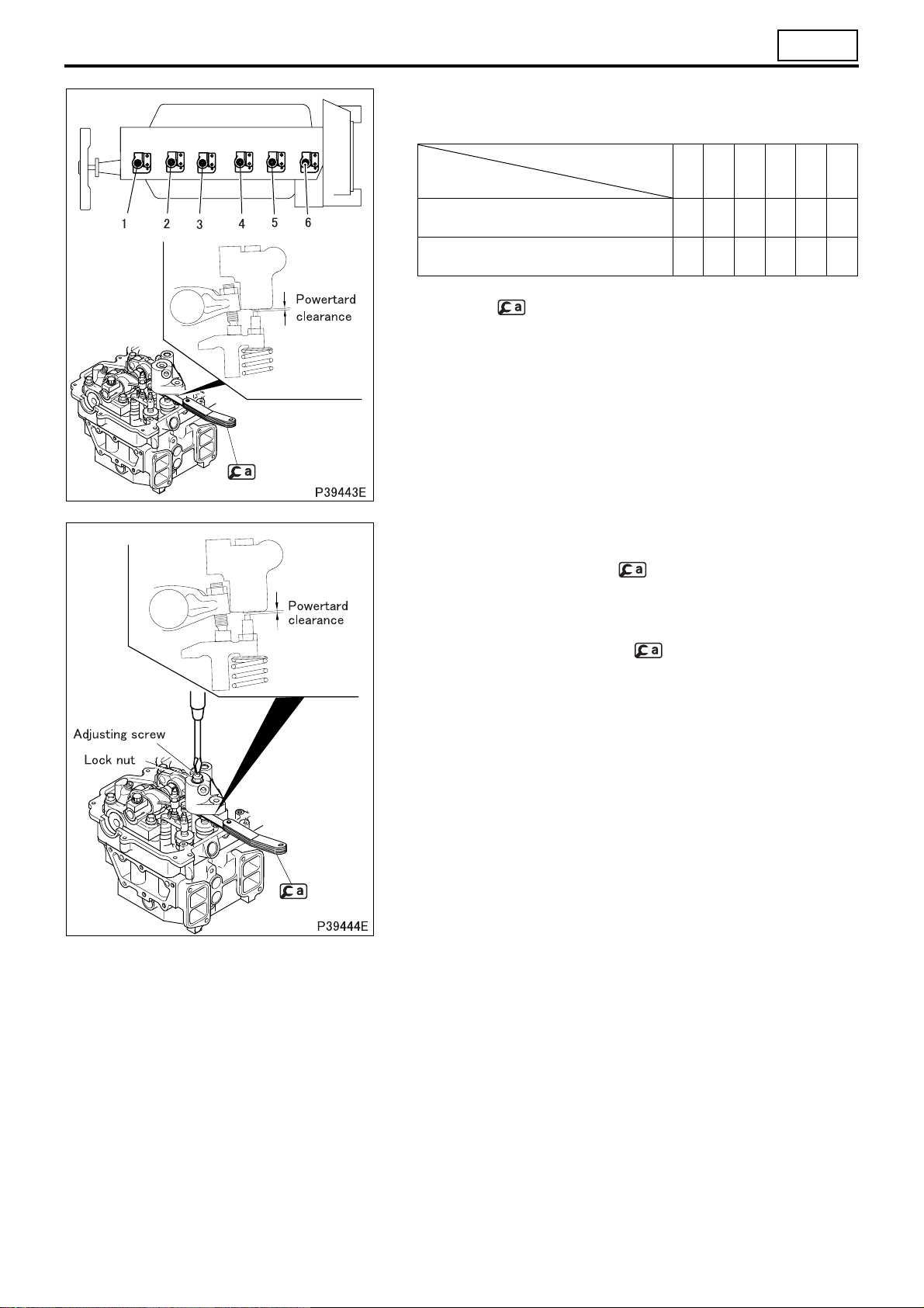
• When the No. 1 or No. 6 piston is at the TDC position of its com-
pression stroke, measure Powertard clearance for the valve
marked
O in the following table.
• For proper measurement, some resistance must be felt when in-
serting the
in the clearance.
• Accurate measurements cannot be expected if the gauge moves
loosely in the clearance.
• If any measurement is out of specification, make adjustment as
follows.
[Adjustment]
• To adjust Powertard clearance, loosen the lock nut, then tighten
the adjusting screw until the moves somewhat stiffly in the
gap.
• Holding the adjusting screw in that position with a screwdriver,
tighten the lock nut to lock the adjusting screw. Recheck the
Powertard clearance using the .
Cylinder No.
Powertard
clearance measuring point
123456
No. 1 piston at TDC of compression
stroke
OOO
No. 6 piston at TDC of compression
stroke
OOO
11-22
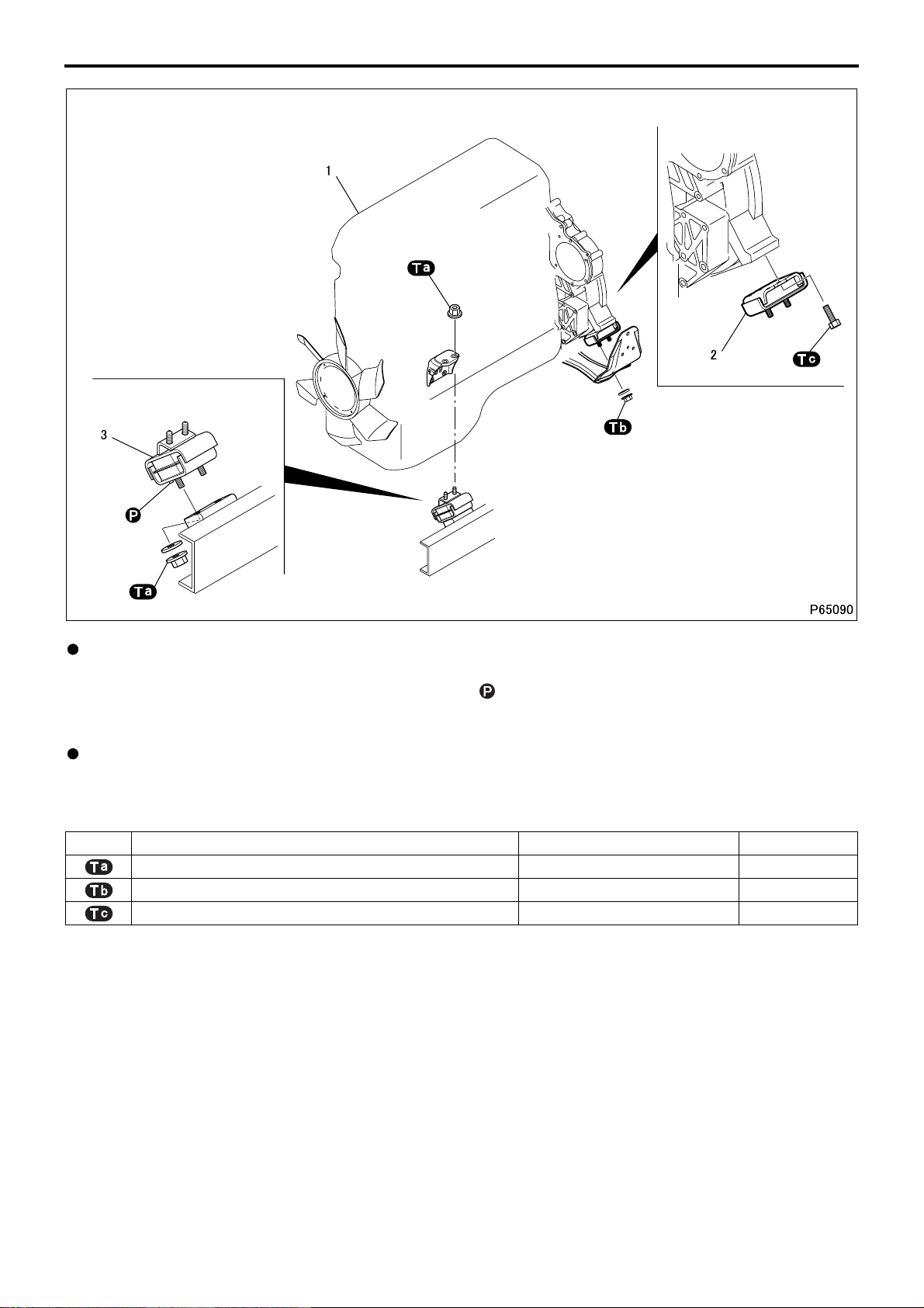
Removal sequence
Installation sequence
Follow the removal sequence in reverse.
Tightening torque (Unit: N·m {kgf·m})
Mark Parts to be tightened Tightening torque Remarks
Nut (front mounting installation) 300 to 400 {30 to 40} –
Nut (rear mounting installation) 120 to 160 {12 to 16} –
Bolt (rear mounting installation) 70 to 95 {7.0 to 9.5} –
1 Engine
2 Rear mounting
3 Front mounting
: Locating pin
ENGINE REMOVAL AND INSTALLATION
11
11-23
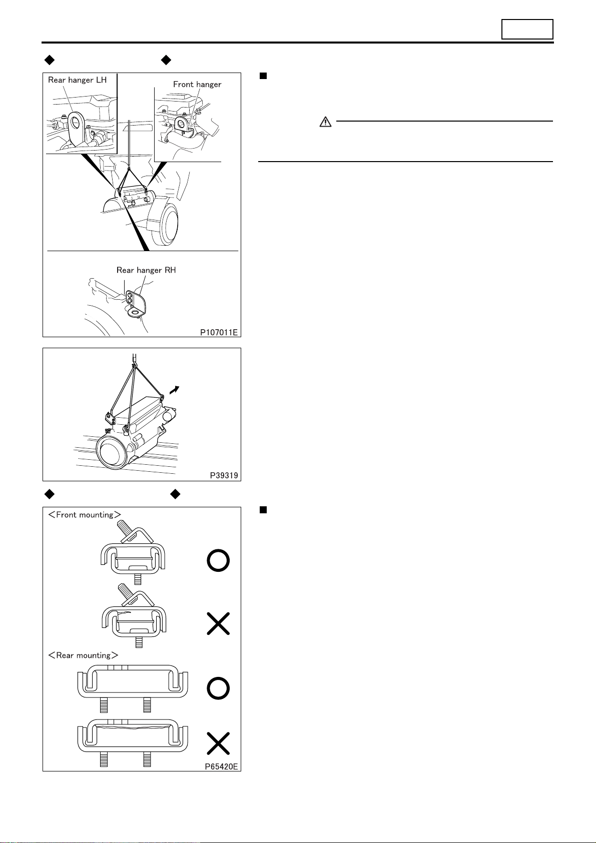
Removal procedure
Removal: Engine
• Hook a lifting device onto front hanger, rear hanger RH and rear
hanger LH, and lift the device with a crane until it is taut.
WARNING
• Use a lifting device that can comfortably withstand the
mass of the engine (approx. 1000 kg).
• Ensure that the harnesses, piping and other relevant parts have
been disconnected.
• Remove the bolts and nuts from the engine mounts. Slowly lift
the engine, taking care not to hit the engine against the frame or
cab.
• Once the bottom of the engine is out of the frame, turn the en-
gine by 90° and remove it out of the vehicle.
Inspection procedure
Inspection: Mounting
• Check the entire circumference of the rubber cushion of the
mountings for a crack, breakage and adhesion of oil.
• If there is any abnormality, replace the mounting.
11-24
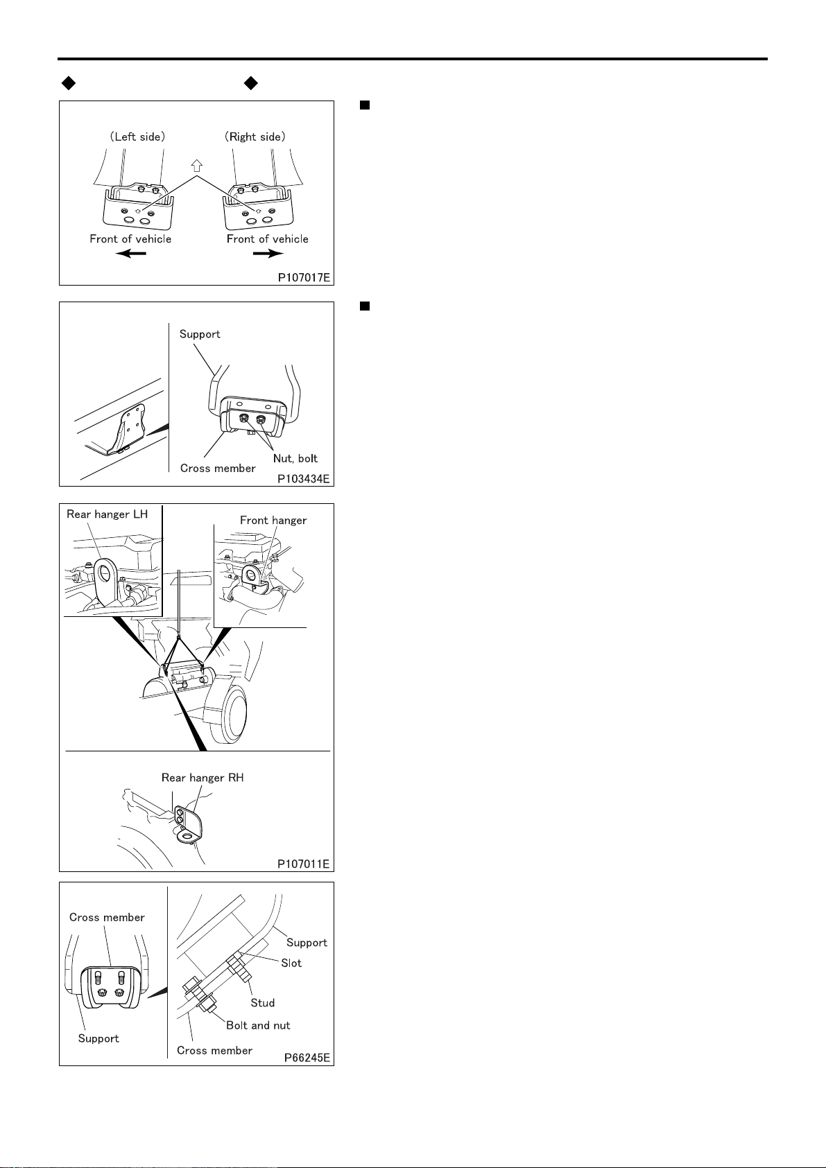
Installation procedure
Installation: Rear mounting
• Install the rear mounting on the engine in the illustrated direc-
tion.
Installation: Engine
• Loosen cross member and support mounting bolts and nuts.
• Hook a lifting device onto front hanger, rear hanger RH and rear
hanger LH, and lift the device with a crane to install the engine.
• Make sure that the stud of the rear mounting is placed at the il-
lustrated position (lowermost part of the slot on the support
side).
• The slot on the cross member side needs not necessarily be on
the lowermost part.
• If the stud is not placed at the illustrated position, adjust the posi-
tion with the cross member and support.
• Tighten cross member and support mounting bolts and nuts to
the torque of 120 to 160 N·m {12 to 16 kgf·m}.
• Tighten front and rear mounting nuts to the specified torque.
ENGINE REMOVAL AND INSTALLATION

M E M O
11-25
11
11-26
M
ITSUBISHI 6M70 ROCKER COVER, ROCKER AND SHAFT
11
11-27
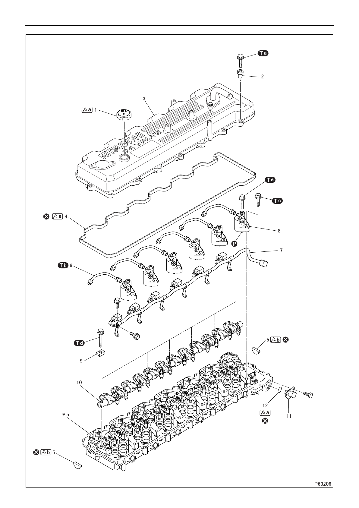
Disassembly sequence
Assembly sequence
Follow the disassembly sequence in reverse.
Tightening torque (Unit: N·m {kgf·m})
Lubricant and/or sealant
Work before removal
Releasing valve spring force
• Before loosening the rocker and shaft mounting bolts, check
whether the valve springs are compressed by the rockers. If so,
loosen the adjusting screws on the rockers to relieve the spring
force. This will eliminate the possibility of compressed springs
damaging parts when they are released.
Installation procedure
Installation: Packing
• Apply sealant over the periphery of the packing and immediately
install it on the rocker case.
• After installing it on the rocker case, apply sealant over the top of
the packing.
• Install the rocker gasket and rocker cover on it immediately after
applying sealant.
CAUTION
• Never run the engine for one hour after installation.
• If the rocker cover is removed after installation, never fail to
replace the packing and apply the sealant again.
Mark Parts to be tightened Tightening torque Remarks
Bolt (rocker cover mounting)
8.8 {0.9} 6.5 Ft Lbs
–
Oil pipe 44 {4.5} –
M10 bolt (slave piston housing mounting) 55 {5.5} –
Bolt (rocker shaft mounting) 98 {10} –
M12 bolt (slave piston housing mounting) 80 {8.0} –
Mark Points of application Specified lubricant and/or sealant Quantity
Rubber portion of oil filler cap
Engine oil As requiredO-ring
Rocker cover gasket
Periphery and top surface of packing ThreeBond 1211 As required
1 Oil filler cap
2 Rubber
3 Rocker cover
4 Rocker cover gasket
5 Packing
6 Oil pipe
7 Harness
8 Slave piston housing
9 Rocker shaft cap
10 Rocker and shaft
(See later section.)
11 Bushing connector
12 O-ring
*
a: Rocker case
: Locating pin
: Non-reusable parts
11-28
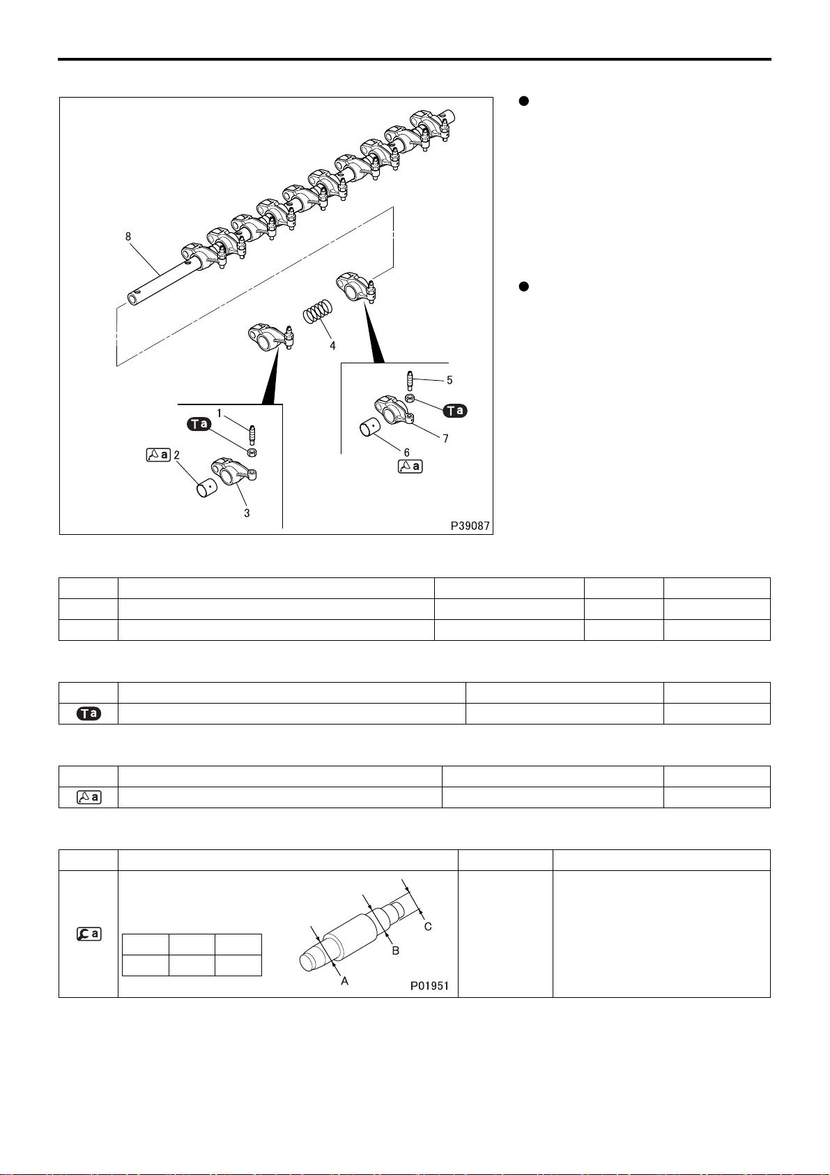
Rocker and Shaft
Disassembly sequence
1 Adjusting screw
2 Rocker bushing
3 Intake rocker
4 Rocker shaft spring
5 Adjusting screw
6 Rocker bushing
7 Exhaust rocker
8 Rocker shaft
Assembly sequence
Follow the disassembly sequence in re-
verse.
Service standards (Unit: mm)
Tightening torque (Unit: N·m {kgf·m})
Lubricant and/or sealant
Special tools (Unit: mm)
Location Maintenance item Standard value Limit Remedy
2, 6, 8 Clearance between rocker shaft and bushing 0.027 to 0.088 0.2 Replace
3, 7 Radial clearance of rocker (roller) 0.068 to 0.112 – Replace
Mark Parts to be tightened Tightening torque Remarks
Lock nut (adjusting screw tightening) 60 {6} –
Mark Points of application Specified lubricant and/or sealant Quantity
Inside surface of rocker bushing Engine oil As required
Mark Tool name and shape Part No. Application
ME350053
Removal and installation of rocker
bushing
Rocker bushing puller
ABC
φ 27.6 φ 30.5 φ 28
ROCKER COVER, ROCKER AND SHAFT
11
11-29
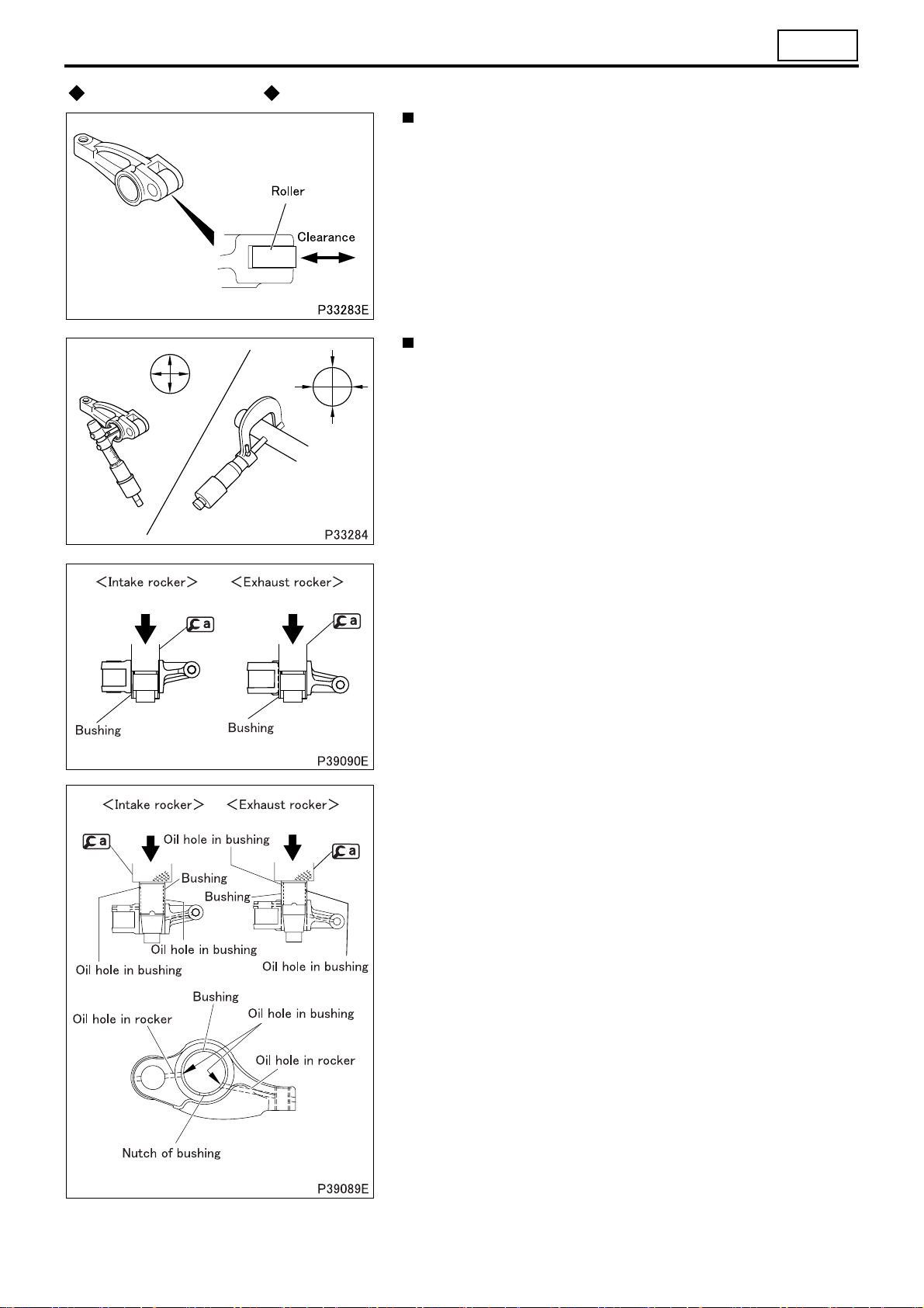
Inspection procedure
Inspection: Radial clearance of rocker (roller)
• If the measurement deviates from the standard value, replace
the defective part(s).
Inspection: Clearance between rocker shaft and bushing
• If the measurement exceeds the limit, replace the bushing.
Replace of rocker bushing
[Removal]
[Installation]
• Assemble the bushing onto the rocker such that the oil holes are
aligned as shown in the illustration.
• After assembly, measure the clearance again.
• If the measurement is less than the standard value, ream the
bushing.
11-30
M
ITSUBISHI 6M70 CAMSHAFT AND ROCKER CASE

11
11-31
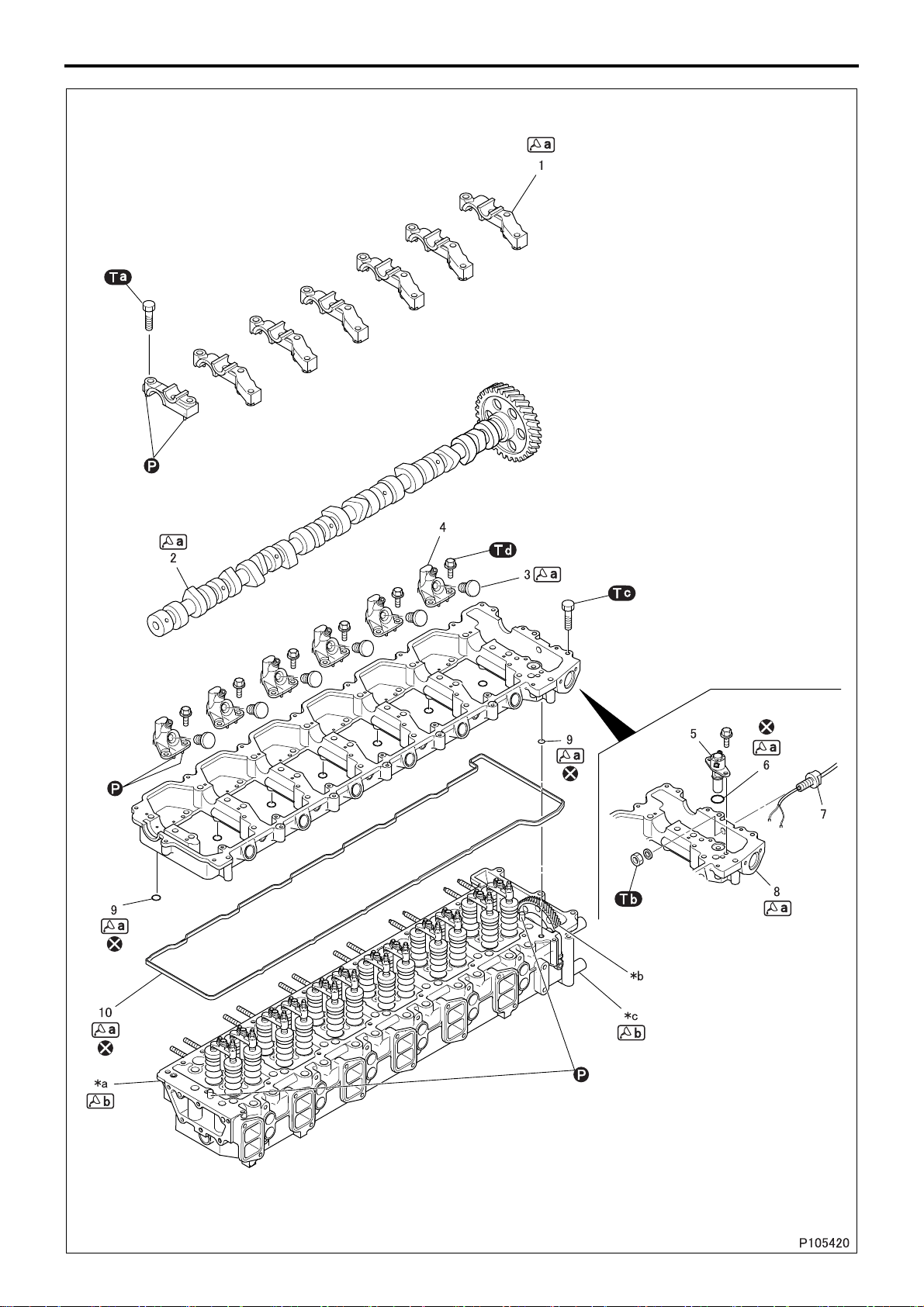
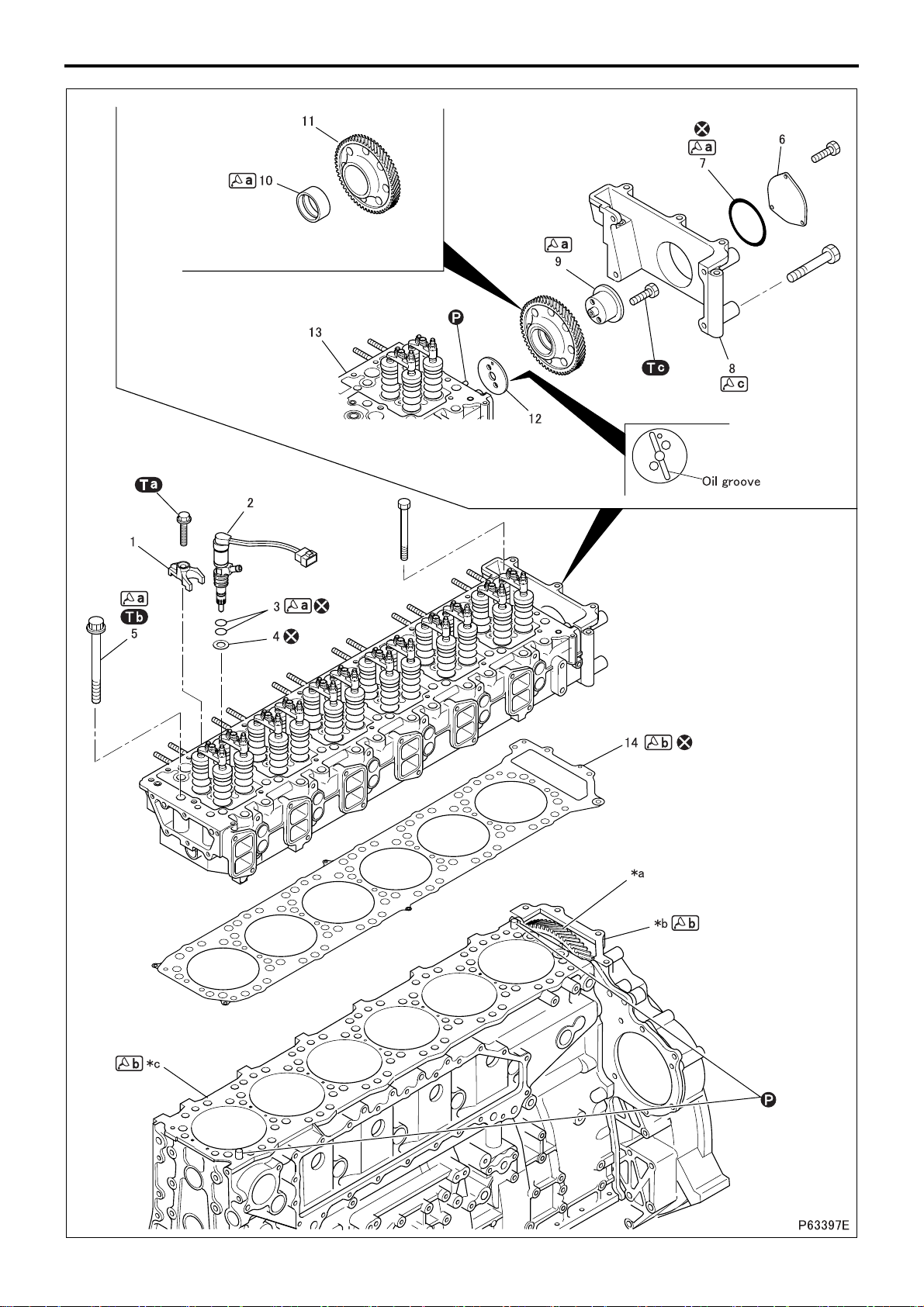
Disassembly sequence
CAUTION
• The rocker case and the camshaft caps have been machined together, which means that they all must be
replaced together. The removed camshaft caps must be identified by attaching tags with their cylinder
numbers because they must be reinstalled to their original positions on the rocker case.
• Do not remove the Powertard solenoid valve unless necessary for replacement.
Assembly sequence
Follow the disassembly sequence in reverse.
Service standards (Unit: mm)
Tightening torque (Unit: N·m {kgf·m})
Lubricant and/or sealant
Location Maintenance item Standard value Limit Remedy
– Camshaft end play 0.1 to 0.2 0.4 Replace
2,
*
b Backlash between idler gear D and camshaft gear 0.112 to 0.165 0.35 Replace
5
Powertard solenoid valve resistance (at temperature
25°C)
32.6 to 39.8
Ω –Replace
Mark Parts to be tightened Tightening torque Remarks
Bolt (camshaft cap mounting) 80 {8} –
Nut (connector mounting) 49 {5.0} –
Bolt (rocker case mounting) 19 {1.9} –
Bolt (master piston housing mounting) 54 {5.5} –
Mark Points of application Specified lubricant and/or sealant Quantity
Camshaft journals and cams
Engine oil As required
Outer periphery of master piston
O-ring
Camshaft journal supports on rocker case
Camshaft journal supports on camshaft cap
Rocker case gasket
Top mating surfaces of cylinder head and timing gear
case
ThreeBond 1211 As required
1 Camshaft cap
2 Camshaft
(See later section.)
3 Master piston
4 Master piston housing
5 Powertard solenoid valve
6 O-ring
7 Connector
8 Rocker case
9 O-ring
10 Rocker case gasket
*
a: Cylinder head
*
b: Idler gear D
*
c: Timing gear case
: Locating pin
: Non-reusable parts
11-32
Work before removal
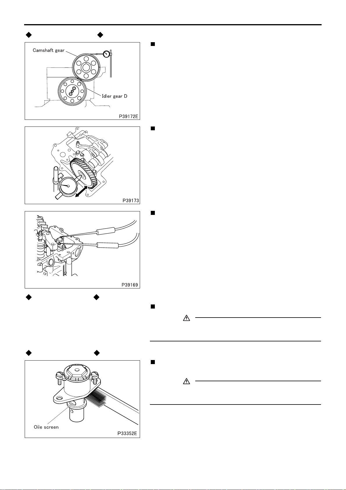
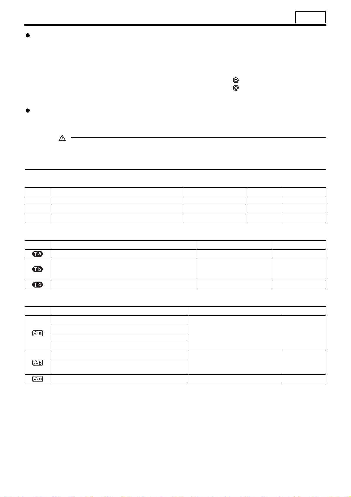
Inspection: Backlash between idler gear D and camshaft
gear
• Measure the backlash at least at three different locations. If the
measurement exceeds the limit, replace the defective part(s).
Inspection: Camshaft end play
• If the measurement exceeds the limit, replace the defective
part(s).
Inspection: Resistance in Powertard solenoid valve
• If the measurement deviates from the standard value, replace
the Powertard solenoid valve.
Removal procedure
Removal: Rocker case gasket
CAUTION
• Be careful not to scratch the cylinder head and timing gear
case when removing the rocker case gasket.
Cleaning procedure
Cleaning: Powertard solenoid valve
• Brush the oil screen clean and dry it with compressed air.
CAUTION
• Do not use a wire brush for cleaning. It could damage the oil
screen.
CAMSHAFT AND ROCKER CASE
11
11-33
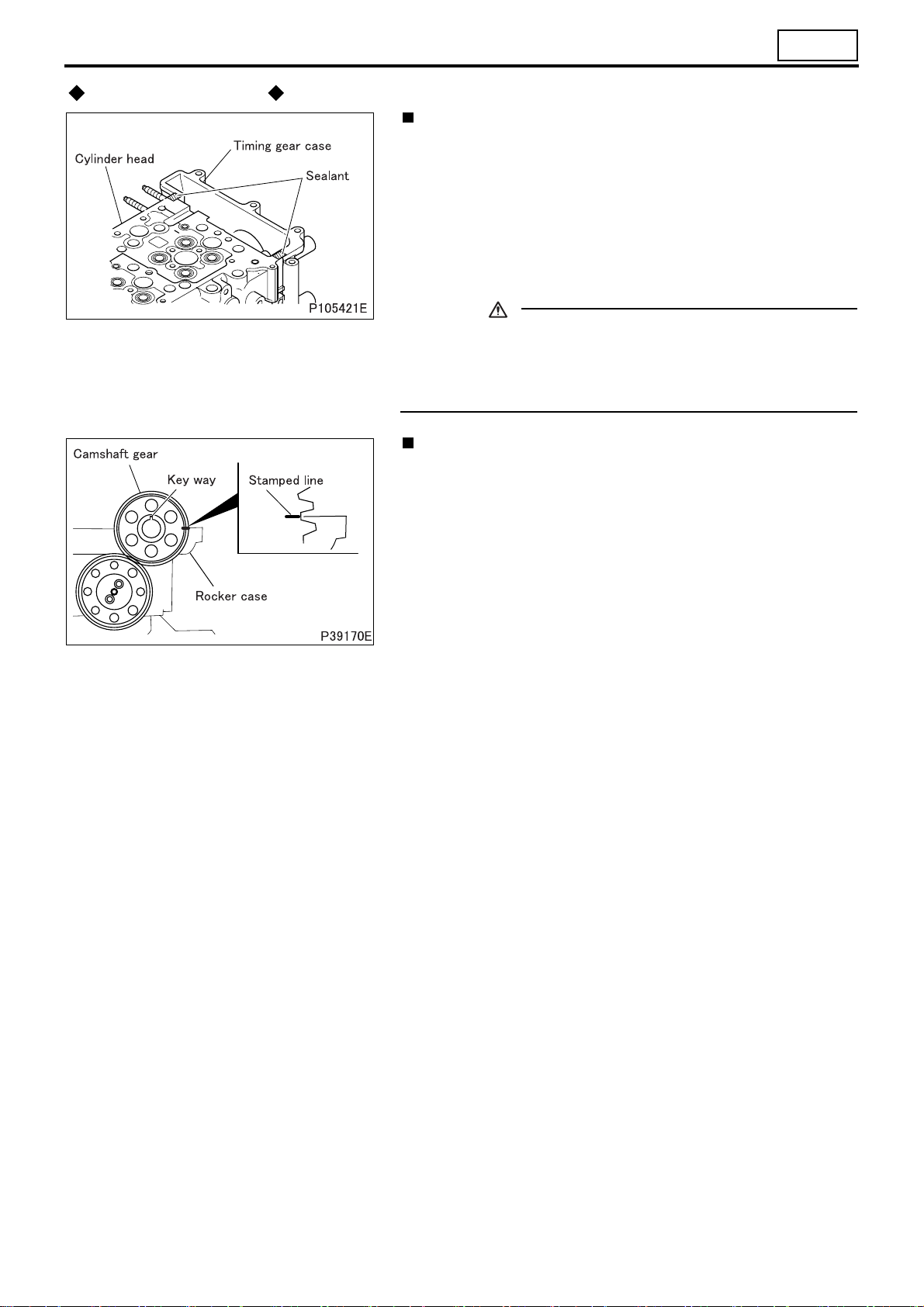
Installation procedure
Installation: Rocker case
• Remove oil or any other contamination from the surfaces where
sealant is to be applied.
• Apply sealant onto the areas (shown in the illustration) on the
top surfaces of the cylinder head and timing gear case. Take
care not to spread the sealant beyond the application areas dur-
ing installation.
• Within three minutes following the application, install the rocker
case together with the rocker case gasket on the cylinder head.
CAUTION
• Do not start the engine for at least an hour after installation.
• Whenever the rocker case mounting bolts are subsequently
loosened or removed, the rocker case gasket must be re-
placed and sealant reapplied upon reassembly.
Installation: Camshaft
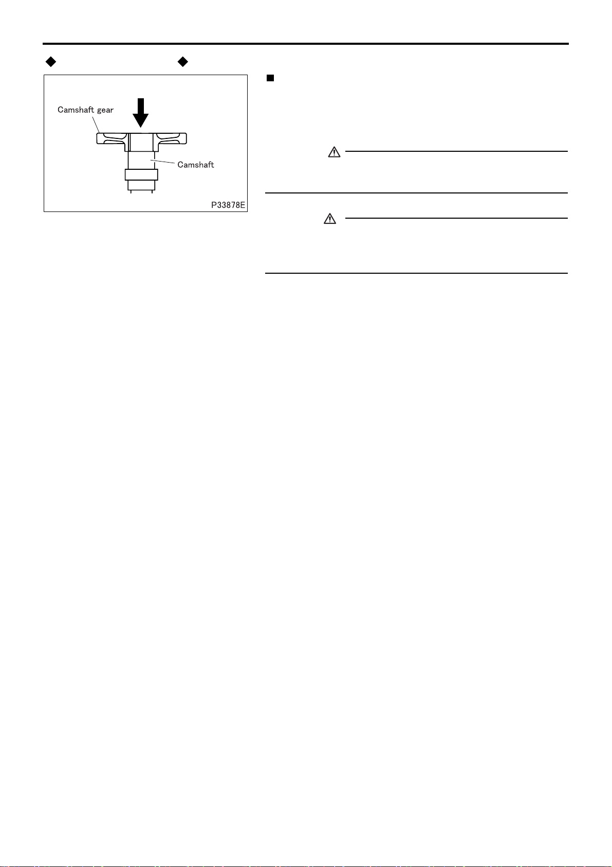
• Make sure that each alignment mark is aligned.
• Install the camshaft such that the stamped line on the camshaft
gear is level with the top surface of the rocker case.
11-34
Camshaft
Disassembly sequence
1 Camshaft gear
2 Key
3 Camshaft
: Non-reusable parts
Assembly sequence
Follow the disassembly sequence in re-
verse.
Service standards (Unit: mm)
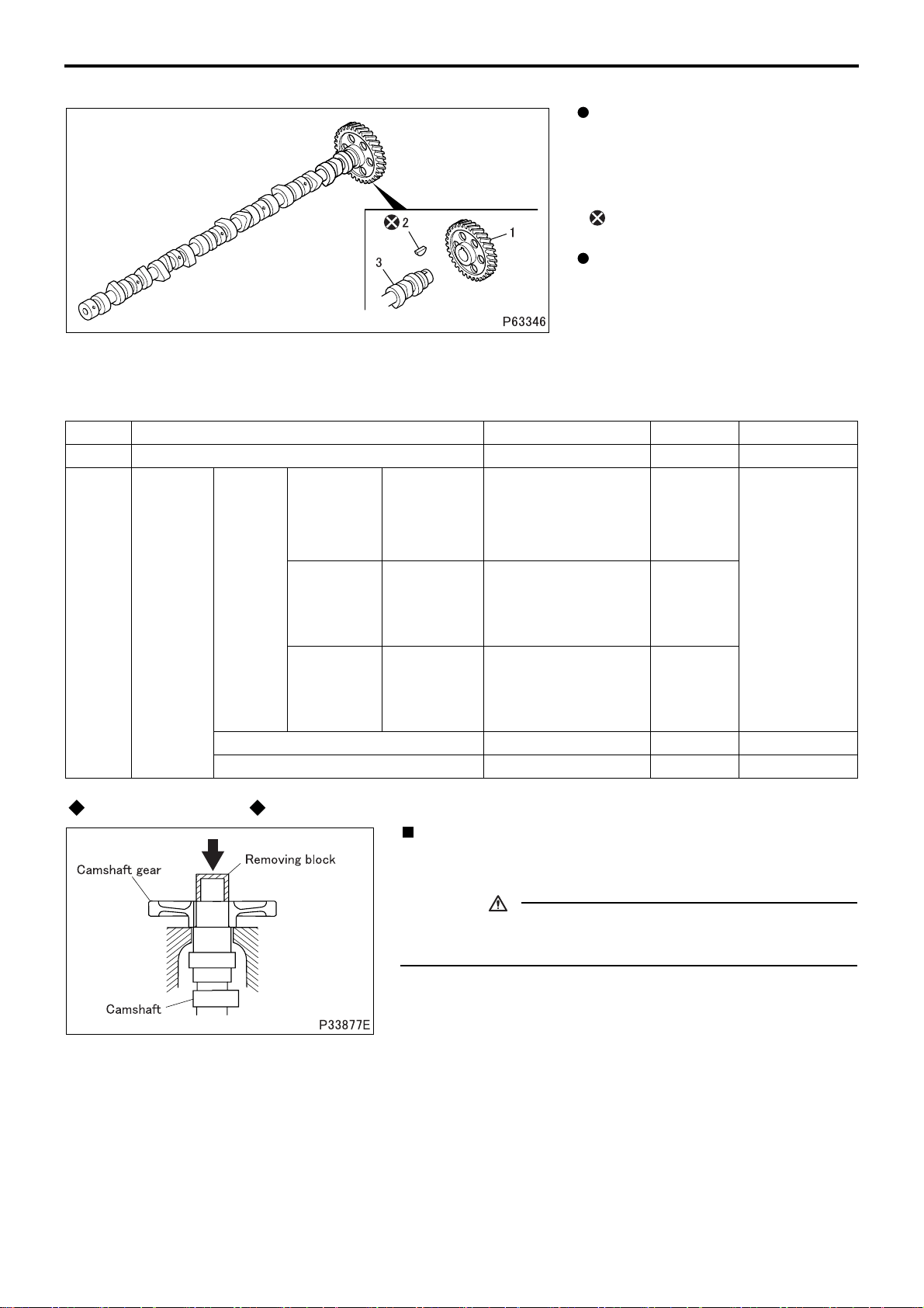
Removal procedure
Removal: Camshaft gear
• Remove the camshaft gear by pushing on the end of the cam-
shaft with a press or other similar tool.
CAUTION
• Do not attempt to remove the camshaft gear with a hammer
as damage will result. Use a press or other similar tool.
Location Maintenance item Standard value Limit Remedy
1, 3 Interference between camshaft gear and camshaft 0.017 to 0.058 – Replace
3 Camshaft
Differ-
ence of
cam lobe
diameter
and base
circle di-
ameter
Intake side
Lobe diame-
ter : 61.233
8.233 7.74
Replace
Base circle
diameter :
53.000
Exhaust side
Lobe diame-
ter : 61.367
Base circle
diameter :
53.133
8.234 7.72
Powertard
Lobe diame-
ter : 60.147
Base circle
diameter :
53.130
7.017 6.52
Bend 0.05 0.08 Replace
Oil clearance at journal 0.082 to 0.127 0.28 Replace
CAMSHAFT AND ROCKER CASE
M
itsubishi 6M70 Engine Parts contact:
email: [email protected]
Phone: 269 673 1638
11
11-35
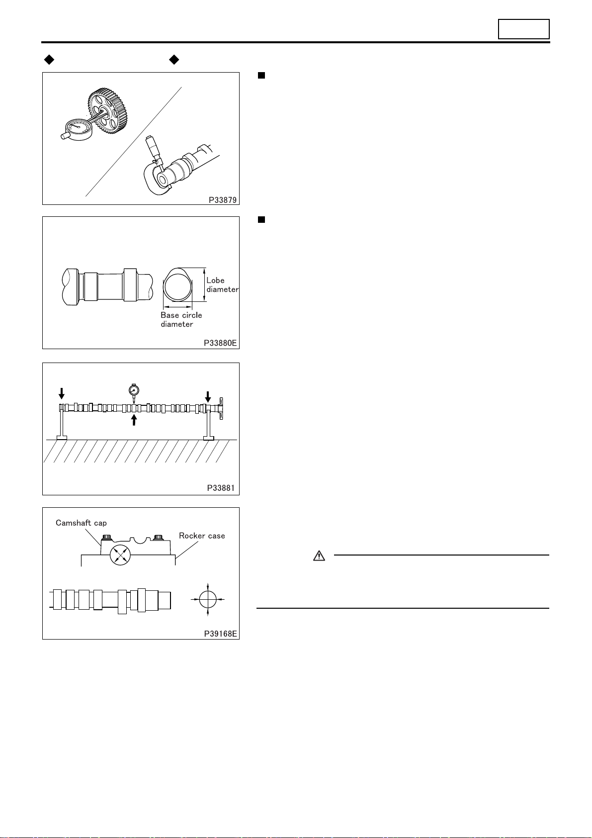
Inspection procedure
Inspection: Interference between camshaft gear and cam-
shaft
• If the measurement deviates from the standard value, replace
the defective part(s).
Inspection: Camshaft
(1) Difference of cam lobe diameter and base circle diameter
• If the measurement is less than the limit, replace the camshaft.
(2) Bend
• Measure the camshaft at the center journal for bend while sup-
porting the shaft at the end journals.
• A half of the dial gauge reading obtained as the camshaft is ro-
tated by a full turn represents the bend of the camshaft.
• If the measurement exceeds the limit, replace the camshaft.
(3) Oil clearance at journal
• If the measurement exceeds the limit, replace the defective
part(s).
CAUTION
• The camshaft cap and rocker case have been machined to-
gether, which means that they all must be replaced togeth-
er.
11-36
Installation procedure
Installation: Camshaft gear
• Heat the camshaft gear to approximately 150°C using a gas
burner.
• While facing the camshaft gear as shown in the illustration,
press it onto the camshaft until it seats snugly on the camshaft.
WARNING
• You may burn yourself if you touch the heated camshaft
gear.
CAUTION
• When installing the camshaft gear, be sure to apply the load
with the press at the center of the gear. Apply the load on
the gear may damage the gear.
CAMSHAFT AND ROCKER CASE

M E M O
11-37
11
11-38
MITSUBISHI 6M70 CYLINDER HEAD AND VALVE
MECHANISM
11
11-39
Disassembly sequence
Assembly sequence
Follow the disassembly sequence in reverse.
CAUTION
• The cylinder head bolt is tightened within the plastic region. The number of punch marks indicates the
number of times the bolt has been tightened. If there are 3 punch marks (tightened 3 times in the past), re-
place the bolt.
Service standards (Unit: mm)
M
itsubishi 6M70 Tightening torque (Unit: N·m {kgf·m})
Lubricant and/or sealant
Location Maintenance item Standard value Limit Remedy
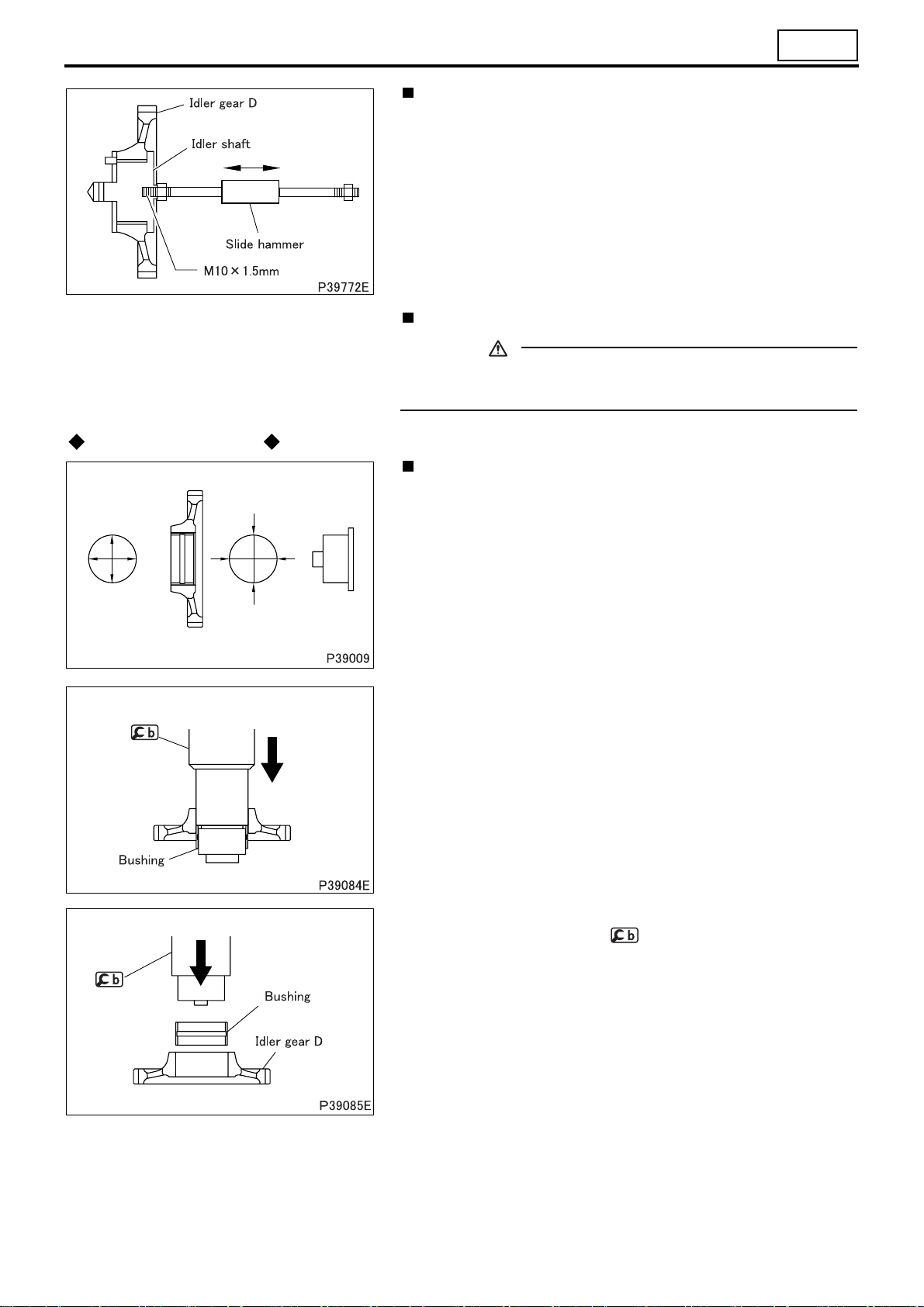
9, 10 Clearance between idler shaft and idler gear bushing 0.03 to 0.068 0.2 Replace
11 Idler gear D end play 0.1 to 0.2 0.4 Replace
11,
*
a Backlash between idler gear D and idler gear C 0.094 to 0.181 0.35 Replace
Mark Parts to be tightened Tightening torque Remarks
Bolt (nozzle bridge mounting) 54 {5.5} –
Mitsubishi 6M70 Cylinder head bolt
180 NM {18 kgfm} 133 Ft Lbs
Plus + 90°
• Wet
• Can be reusable
up to 3 times
Bolt (idler shaft mounting) 55 {5.5} –
Mark Points of application Specified lubricant and/or sealant Quantity
O-ring
Engine oil As required
Threaded of bolt
Outer periphery of idler shaft
Inside surface of idler gear bushing
Top mating surfaces of flywheel housing and crankcase
ThreeBond 1211 As required
Mating surfaces of cylinder head on cylinder head gasket
top surface and timing gear case
Mating surfaces of cylinder head and timing gear case ThreeBond 1207C As required
1 Nozzle bridge
2 Injector (See Gr13.)
3 O-ring
4 Nozzle tip gasket
5 Cylinder head bolt
6 Plate
7 O-ring
8 Timing gear case
9 Idler shaft
10 Idler gear bushing
11 Idler gear D
12 Thrust plate
13 Cylinder head
(See later section.)
14 6M70 Cylinder head gasket
*
a: Idler gear C
*
b: Flywheel housing
*
c:Crankcase
: Locating pin
: Non-reusable parts
Mitsubishi 6M70 Engine Parts contact:
email: EngineParts@HeavyEquipmentRestorationPar
ts.com
Phone: 269 673 1638
11-40
Special tools (Unit: mm)
Work before removal
Inspection: Idler gear D end play
• If the measurement exceeds the limit, replace the defective
part(s).
Inspection: Backlash between idler gear D and idler gear C
• If the measurement exceeds the limit, replace the defective
part(s).
Removal procedure
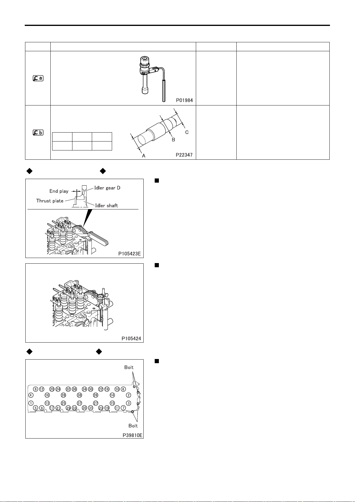
Removal: Cylinder head
• Remove the bolts (× 4).
• Progressively loosen the cylinder head bolts in the order shown
in the illustration, going over them several times, before eventu-
ally removing them.
Mark Tool name and shape Part No. Application
Socket wrench MH063388 Installation of cylinder head
ME350196
Removal and installation of idler gear
bushing
Idler gear bushing-puller
ABC
φ 56 φ 62 φ 57
CYLINDER HEAD AND VALVE MECHANISM
11
11-41
Removal: Idler shaft
• Remove the idler shaft together with idler gear D as a unit with a
slide hammer.
Removal: Cylinder head gasket
CAUTION
• Be careful not to scratch the cylinder head, crankcase and
flywheel housing when removing the cylinder head gasket.
Inspection procedure
Inspection: Clearance between idler shaft and idler gear
bushing
• If the measurement exceeds the limit, replace the bushing.
Replacement of idler gear bushing
[Removal]
[Installation]
• Press in the bushing unt
il
contacts the end face of idler
gear D.
• After installation, measure the clearance again.
• If the measurement is less than the specified value, ream the
bushing.
11-42
Installation procedure
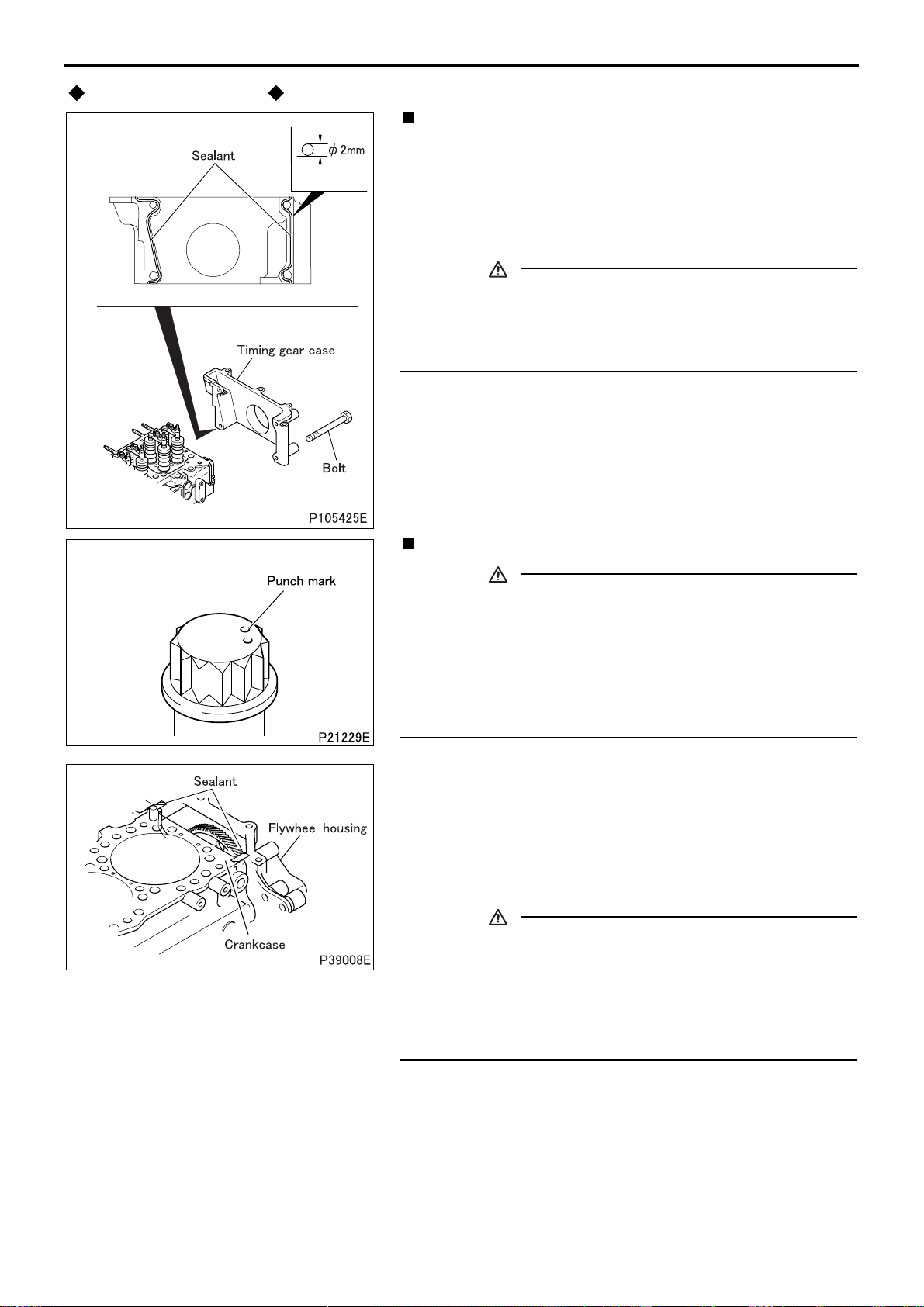
Installation: Timing gear case
• Remove oil or any other contamination from the surfaces where
sealant is to be applied.
• Apply a sealant to the illustrated section of the timing gear case.
• Install the timing gear case to the cylinder head within 3 minutes
following the application of the sealant. Take care not to spread
the sealant beyond the application areas during installation.
CAUTION
• Do not start the engine for at least an hour after installation.
• After reassembly, if the timing gear case mounting bolts are
subsequently loosened or removed, be sure to apply seal-
ant again upon reassembly.
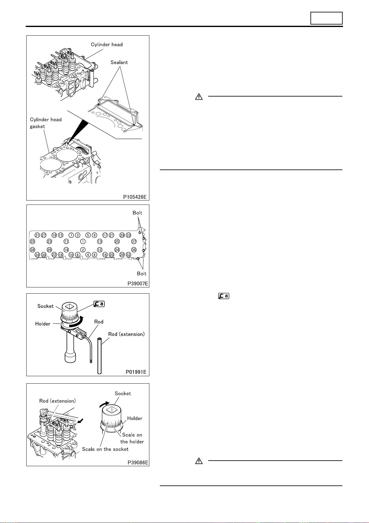
Installation: Cylinder head
CAUTION
• Before installing the Mitsubishi 6M70 cylinder head bolt,
check the number of punch marks on the bolt head.
(Bolts with up to two punch marks can be reused.)
The number of punch marks indicates the number of times
the bolt has been tightened in the past within the plastic re-
gion. If there are three punch marks (tightened three times
in the past), replace the bolt.
• Remove oil or any other contamination from the surfaces where
sealant is to be applied.
• Apply sealant onto the areas (shown in the illustration) on the
top surfaces of the flywheel housing and crankcase.
• Within three minutes following the application, install the cylinder
head gasket onto the crankcase. Take care not to spread the
sealant beyond the application areas during installation.
CAUTION
• Be careful not to scratch the cylinder head gasket when in-
stalling the cylinder head gasket.
• Do not start the engine for at least an hour after installation.
• After reassembly, if the cylinder head bolts are subsequent-
ly loosened or removed, be sure to replace the cylinder
head gasket and apply sealant again upon reassembly.
CYLINDER HEAD AND VALVE MECHANISM
11
11-43
• Remove oil or any other contamination from the surfaces where
sealant is to be applied.
• Install the cylinder head gasket onto the crankcase and apply
sealant to the illustrated section of the cylinder head gasket.
• Within three minutes following the application, install the cylinder
head onto the cylinder head gasket. Take care not to spread the
sealant beyond the application areas during installation.
CAUTION
• Do not start the engine for at least an hour after installation.
• Whenever the cylinder head bolts are subsequently loos-
ened or removed, the cylinder head gasket must be re-
placed and sealant reapplied upon reassembly.
• If pistons, connecting rods or other relevant parts are re-
placed, measure to check the pistons for any change in pro-
trusion. (See “PISTON, CONNECTING ROD AND CYLINDER
LINER”.)
• Tighten the cylinder head bolts to a torque of 180 N·m {18 kgf·m}
in the order shown in the illustration.
• Install the bolts.
• Further tighten the bolts, in the order shown and as follows.
• Turn the holder of counterclockwise to pretension the inter-
nal spring.
• Set
the tool such that the rod (extension) is pressed against the
rocker shaft bracket by the force of the spring.
• Align any line on the holder scale with any line on the socket
scale. (This will be used as the reference point = 0°.)
• From the reference point, turn the socket by 90° in the direction
shown. Each division on the holder scale represents 5°.
• After tightening the cylinder head bolt within the plastic region,
make a punch mark on the bolt head to record the number of
times that they have been tightened.
CAUTION
• The bolts should be tightened within the plastic region.
Never tighten them further than the specified angle.
11-44
Cylinder Head
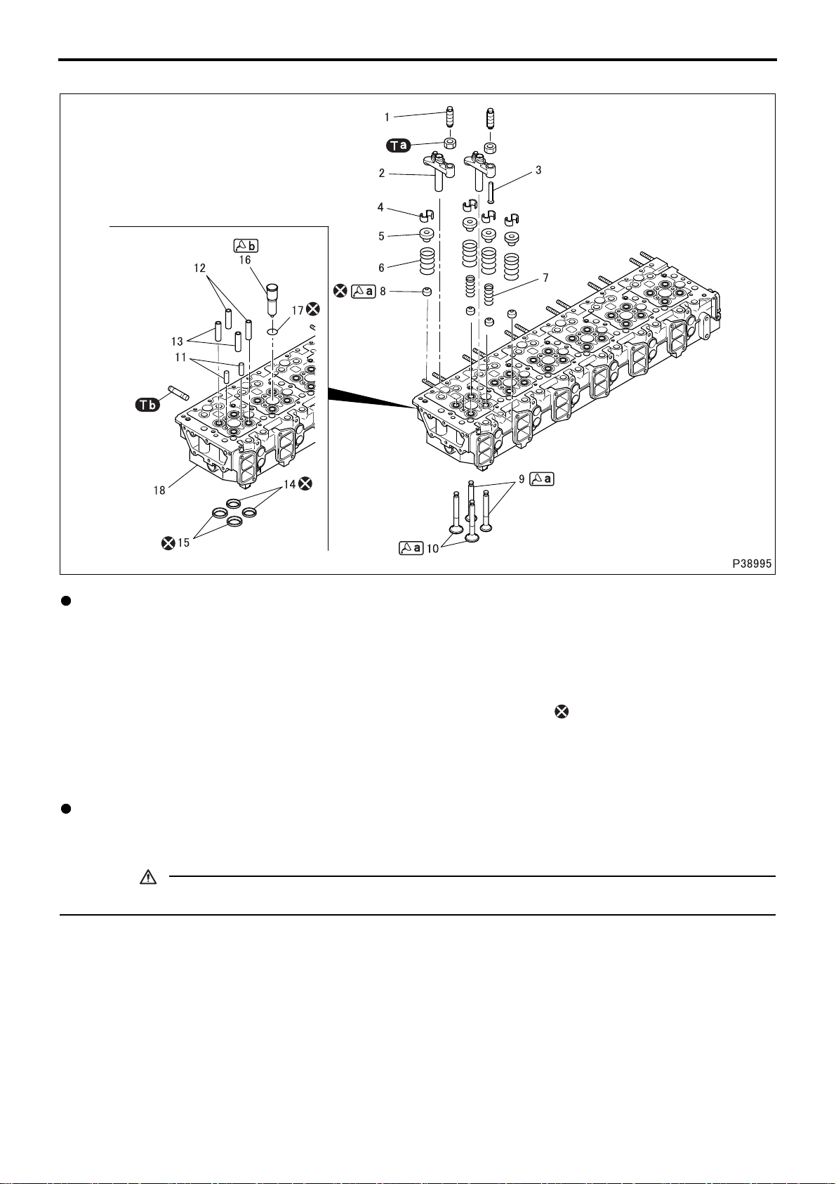
Disassembly sequence
Assembly sequence
Follow the disassembly sequence in reverse.
CAUTION
• When an exhaust valve or intake valve has been removed, make sure to replace the valve stem seal.
1 Adjusting screw
2 Valve bridge
3 Pin
4 Valve cotter
5 Upper retainer
6 Valve spring
<Intake>
Outer valve spring
<Exhaust>
7 Inner valve spring
<Exhaust>
8 Valve stem seal
9 Exhaust valve
10 Intake valve
11 Valve bridge guide
12 Exhaust valve guide
13 Intake valve guide
14 Exhaust valve seat
15 Intake valve seat
16 Nozzle tube
17 O-ring
18 Cylinder head
: Non-reusable parts
M
ITSUBISHI 6M70 CYLINDER HEAD AND VALVE MECHANISM
Mitsubishi 6M70 Engine Parts contact:
email: [email protected]
Phone: 269 673 1638
11
11-45
M
itsubishi 6M70 Service standards (Unit: mm)
Tightening torque (Unit: N·m {kgf·m})
Lubricant and/or sealant
Location Maintenance item Standard value Limit Remedy
2, 11
6M70 V
alve bridge-to-valve bridge guide clearance 0.01 to 0.048 0.1 Replace
6
6M70 Valve spring
<Intake>,
6M
70 outer valve
spring
<Exhaust>
Free length 89.3 87.9 Replace
Installed load
(Installed length 61.325)
490.4 ± 24.5 N
{50.0 ± 2.5 kgf}
–Replace
Squareness – 2.0 Replace
7
6M70 Inner valve
spring
<Exhaust>
Free length 76.0 74.9 Replace
Installed load
(Installed length 54.325)
98.1 ± 4.9 N
{10.0 ± 0.5 kgf}
–Replace
Squareness – 2.0 Replace
9
6M
70
Exhaust valve
Stem outer diameter 9.925 to 9.940 9.85 Replace
Sinkage from cylinder head
bottom surface
0.2 ± 0.25 0.7 Replace
Valve margin 2.5 2.0 Replace
Seat angle 45° ± 15° – Rectify
9, 12
6M70 E
xhaust valve stem-to-valve guide clearance 0.07 to 0.10 0.2 Replace
10
6M
70
Intake valve
Stem outer diameter 9.96 to 9.975 9.85 Replace
Sinkage from cylinder head bottom
surface
0.5 ± 0.25 1.0 Replace
Valve margin 2.83 2.33 Replace
Seat angle 60° ± 15° – Rectify
10, 13
6M
70 Intake valve stem-to-valve guide clearance 0.035 to 0.065 0.2 Replace
11
6M
70 Outer diameter of valve bridge guide 10.989 to 11 10.988 Replace
14
6M70 Exhaust valve seat width
3.5 ± 0.2 4.2
Rectify or
replace
15
6M70 Intake valve seat width
2.8 ± 0.2 3.5
Rectify or
replace
18
6M70
Cylinder head
Bottom surface distortion 0.07 0.2
Rectify or
replace
Height from top surface to
bottom surface
130 ± 0.05 129.5 Replace
Valve seat hole diameter φ 49 – Replace
Mark Parts to be tightened Tightening torque Remarks
Lock nut (valve bridge adjusting screw tightening) 68 {7.0} –
Stud bolt 20 {2.0} –
Mark Points of application Specified lubricant and/or sealant Quantity
Lip of valve stem seal
Engine oil As required
Stem and end of valve
Nozzle tube end ThreeBond 1211 As required
+0.025
0
11-46
Special tools (Unit: mm)
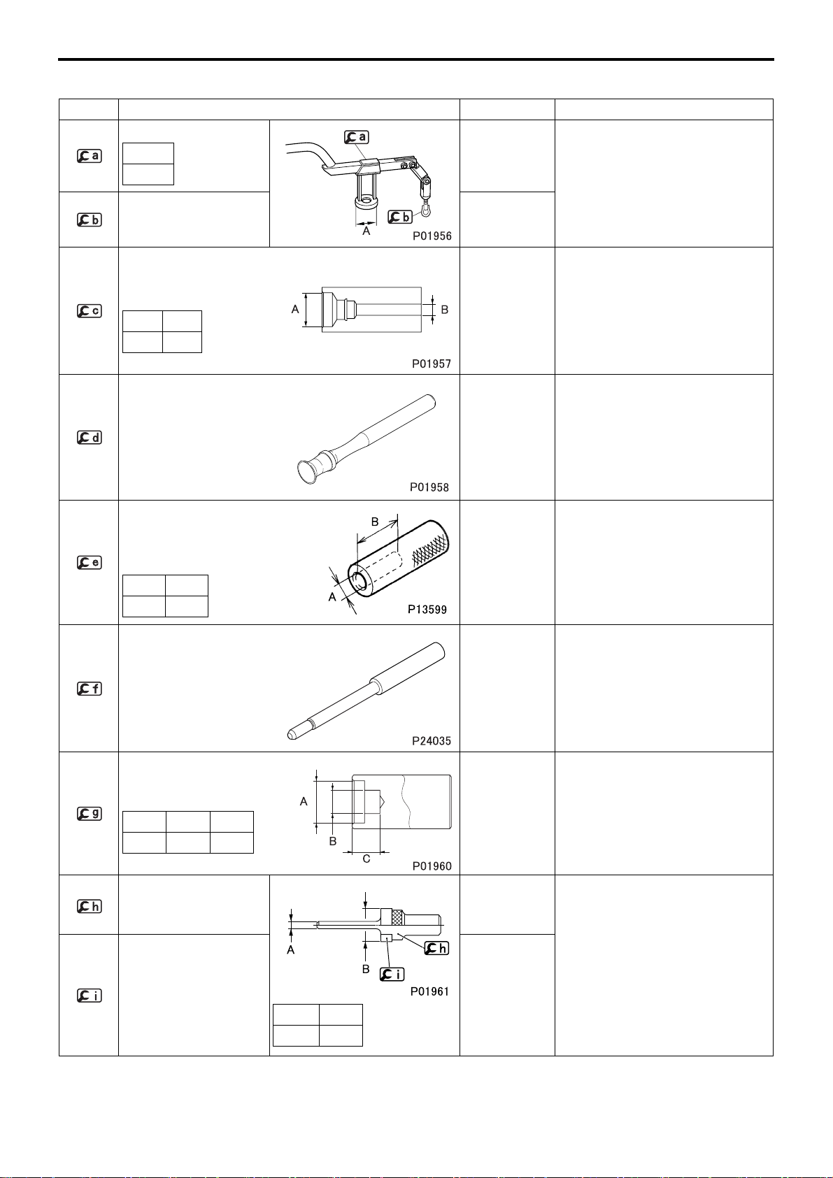
Mark Tool name and shape Part No. Application
Valve lifter
MH061668
Removal and installation of valve cot-
ters
Valve lifter hook MH061679
MH062806 Installation of valve stem seals
Valve lapper 30091-07500 Lapping valves and valve seats
ME350051 Installation of valve bridge guides
Valve guide remover
MH062177 Removal of valve guides
ME350052
Installation of M
itsubishi 6M70
valve guides
Caulking tool body MH062174
Installation of Mitsubis
hi 6M70
intake valve seats ,
exhaust valve seats ,
Installer ring MH062175
A
φ 42
Valve stem seal installer
AB
φ 22 φ 11
Valve bridge guide
installer
AB
φ 11 56
Valve guide installer
ABC
φ 25 φ 15 16.8
AB
φ 10 φ 51
CYLINDER HEAD AND VALVE MECHANISM
11
11-47
Special tools (Unit: mm)
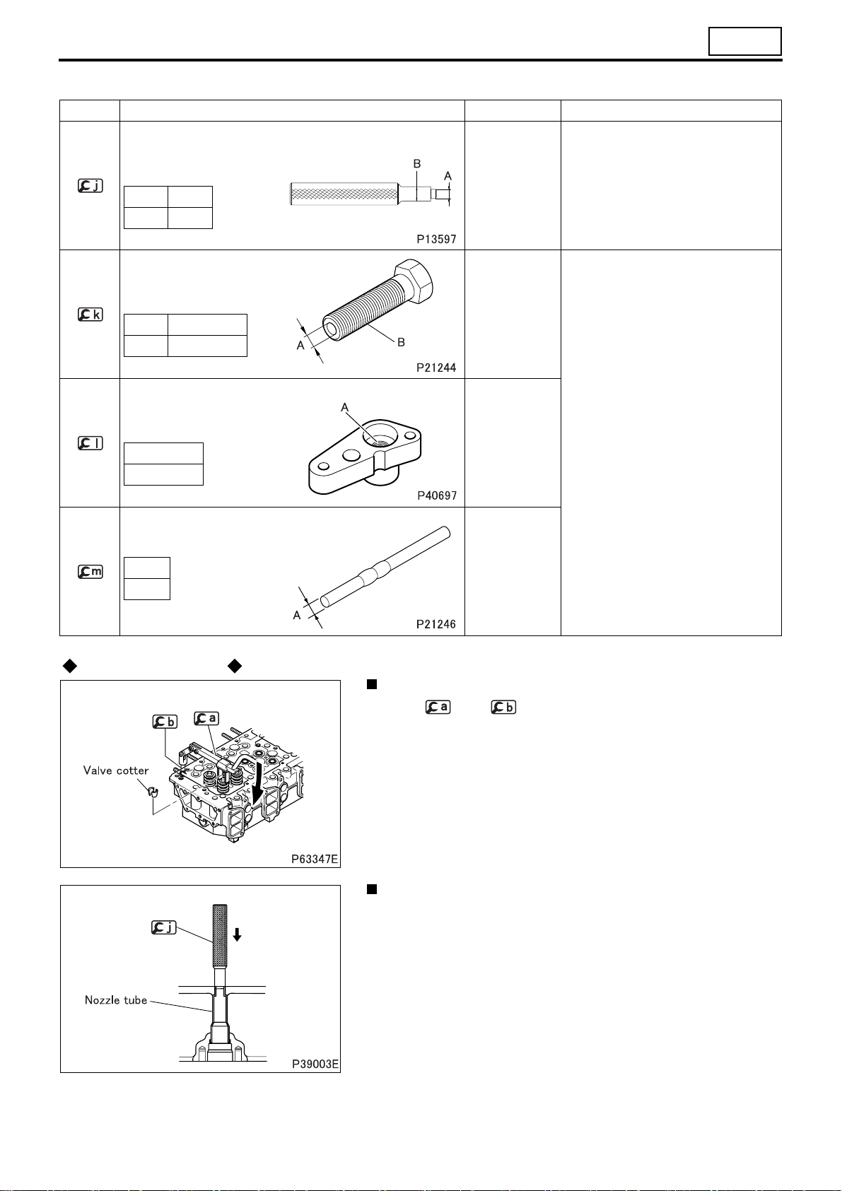
Removal procedure
Removal: Valve cotter
• Using and , evenly compress the valve cotter to re-
move so that the valve spring does not lean to one side.
Removal: Nozzle tube
Mark Tool name and shape Part No. Application
MH061232 Removal of nozzle tube
MH061231
Installation of Mitsubishi 6M70
nozzle tube
ME350195
MH061229
Nozzle tube remover
AB
φ 8.7 φ 12.5
Nozzle tube installer
bolt
AB
φ 8.5 M18
× 1.5
Nozzle tube installer
body
A
M18 × 1.5
Nozzle tube stamp
A
φ 8
11-48
Inspection procedure
Inspection: Valve bridge and valve bridge guide
(1) Valve bridge-to-guide clearance
• If the measurement exceeds the limit, replace the defective
part(s).
(2) Outer diameter of valve bridge guide
• If the measurement is less than the limit or if the parts are un-
evenly worn, replace the valve bridge guide.
Replacement of valve bridge guide
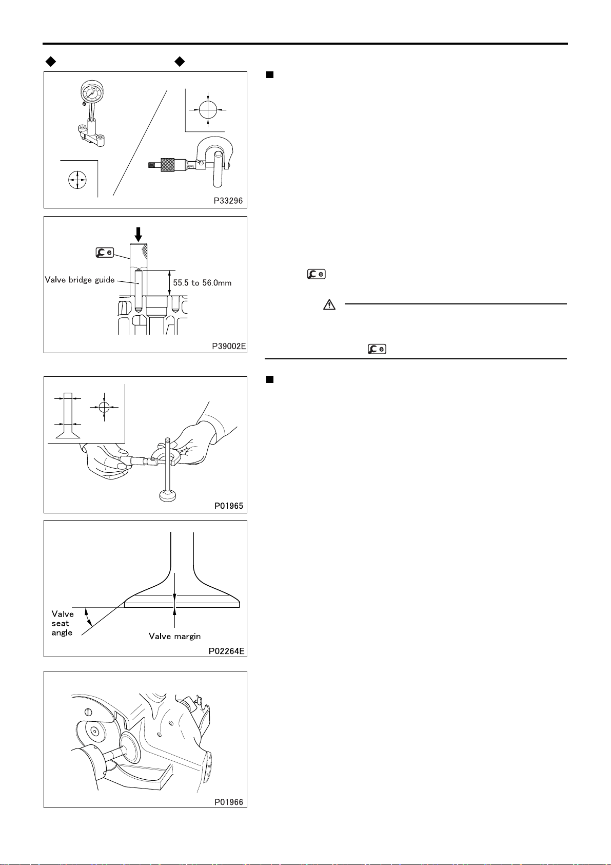
[Installation]
• Before installation, ensure that no water, oil or other foreign mat-
ter is in the installation hole.
• Us
ing , install the valve bridge guide until
it securely contacts
the cylinder head.
CAUTION
• The valve bridge guide must be installed to the specified
depth of the cylinder head. Correct installation can only be
possible by using .
Inspection: Mitsubishi 6M70 Intake and exhaust valve (1)
Valve stem outer diameter
• If the measurement is less than the limit or the valve is worn ex-
tremely unevenly, replace the valve.
• When the valve has been replaced with a new one, make sure to
lap the valve and valve seat.
(2) Valve seat angle
• If the measurement deviates from the standard value, rectify the
valve.
(3) Valve margin
• If the measurement is less than the limit, replace the valve.
Refacing valve
• Limit grinding to a necessary minimum.
• If the valve margin is below the limit after grinding, replace the
valve.
• After grinding, make sure to lap the valve and valve seat.
CYLINDER HEAD AND VALVE MECHANISM
11
11-49
Inspection: Valve-to-valve guide clearance
• If the clearance exceeds the specified limit, replace the defective
part(s).
Replacement of valve guides
[Removal]
[Installation]
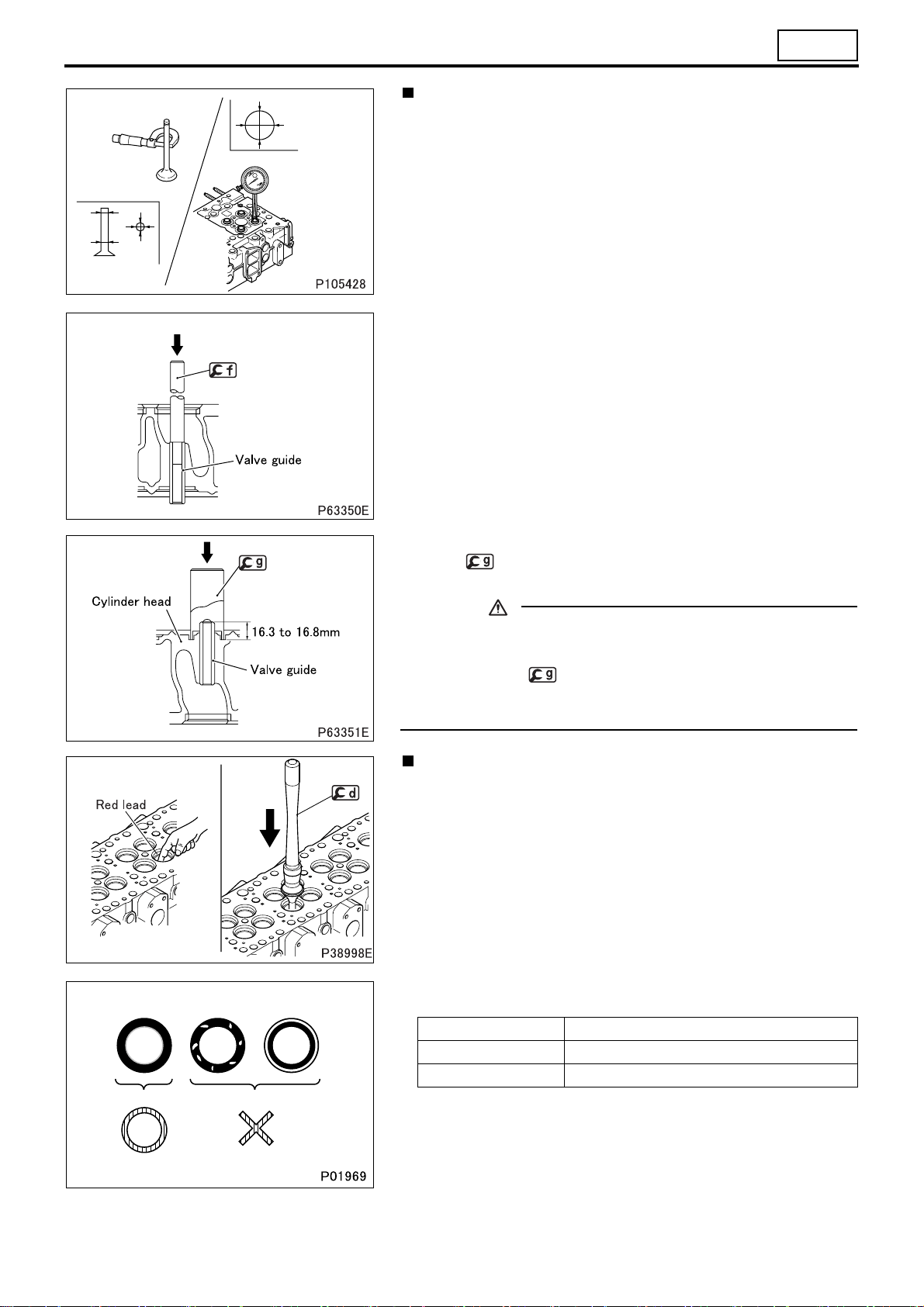
• Us
ing
, install the valve guide until it securely contacts the
cylinder head.
CAUTION
• The valve guide must protrude from the cylinder head by
the specified amount. Correct installation can only be pos-
sible by using .
• The valve guides for the exhaust valves are longer than the
valve guides for the inlet valves.
Inspection: Contact between valve and valve seat
• Before starting inspection, check that the valve and valve guide
are intact.
• Apply an even coat of red lead to the valve contact surface of
the valve seat.
• Strike the valve once against the valve seat. Do not rotate the
valve during this operation.
• If the red lead deposited on the valve indicates a poor contact
pattern, take either of the following corrective actions.
Contact pattern Corrective action
Minor defect Lapping valve
Serious defect Reface or replace valve and valve seat
11-50
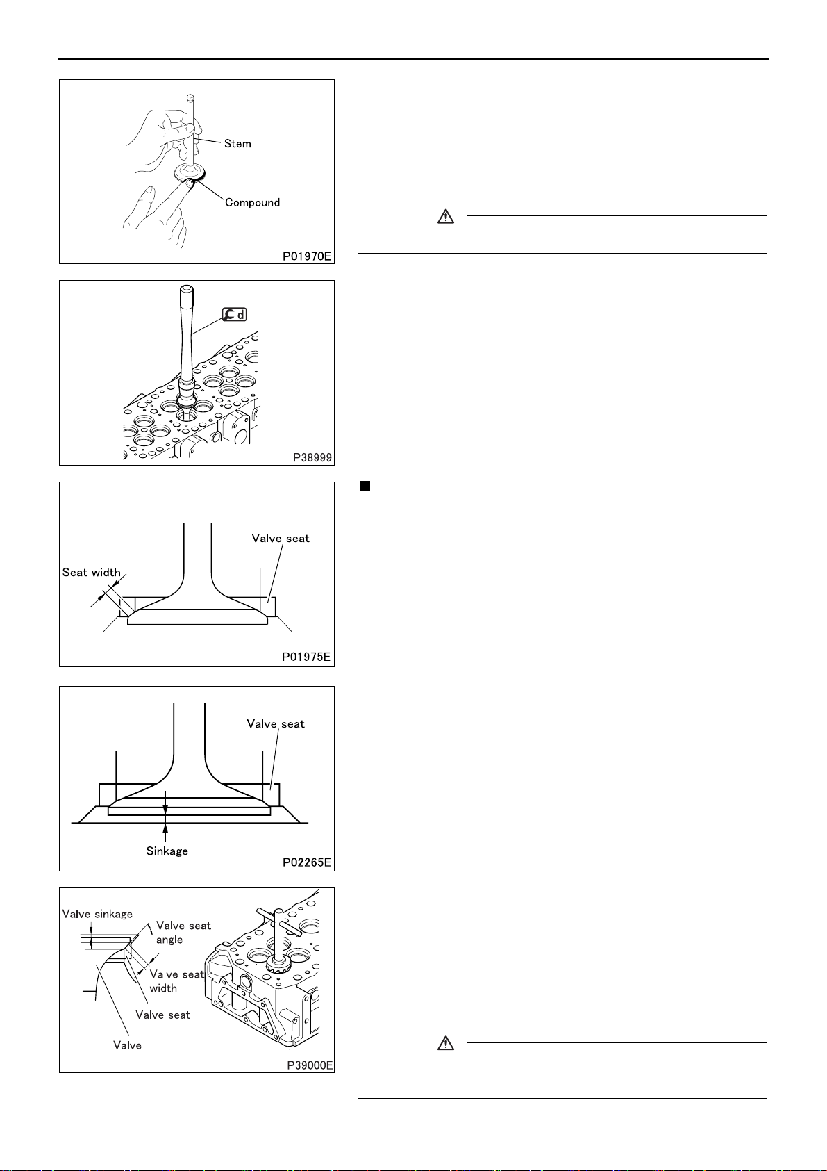
Lapping valve
• Lap the valve in the following sequence.
• Apply a thin coat of lapping compound to the contact surface of
the valve seat. Adding a small amount of engine oil to the lap-
ping compound can facilitate even application.
• Start with an intermediate-grit compound (120 to 150 grit) and
finish with a fine-grit compound (200 grit or more).
CAUTION
• Do not put any compound on the stem.
• Strike the valve several times against the valve seat while rotat-
ing the valve a little at a time.
• Wash away the compound with diesel fuel.
• Apply engine oil to the contact surface of the valve seat and rub
in the valve and seat well.
• Inspect the contact pattern between valve and valve seat again.
• If the contact pattern is still defective, replace the valve seat.
Inspection: Mitsubishi 6M70 Valve seats
• If the valve seat is refaced or replaced after performing the fol-
lowing inspection, make sure to lap the valve and valve seat.
(1) Valve seat width
• If the measurement exceeds the limit, reface or replace the
valve seat.
(2) Valve sinkage from cylinder head bottom surface
• Perform measurement keeping the valve in close contact with
the valve seat.
• If the measurement exceeds the limit, reface or replace the de-
fective part(s).
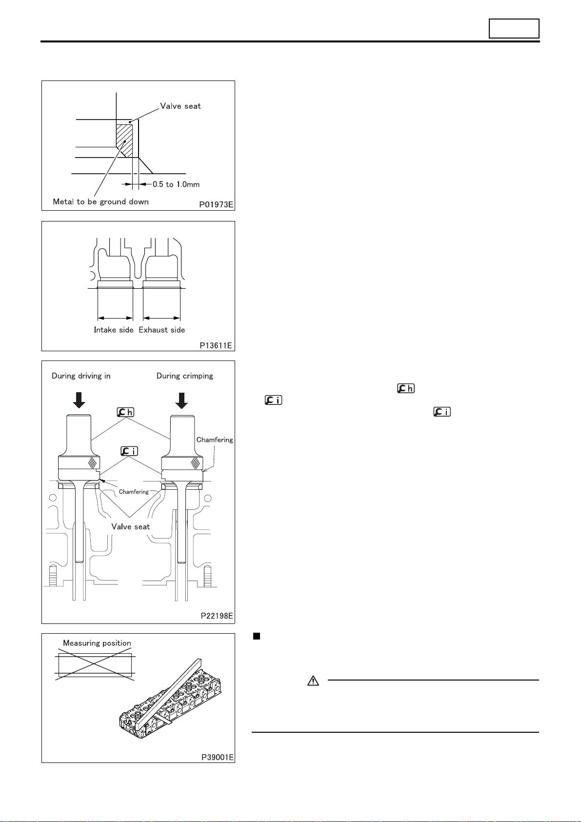
Refacing the valve seat
• Grind the valve seat using a valve seat cutter or valve seat
grinder.
• Place a piece of sandpaper of approximately #400 between the
cutter and valve seat and grind the valve seat lightly.
• Use a 15° or 75° cutter to cut the valve seat width within the
standard range. Replace the valve seat if it cannot be refaced
within the standard range.
CAUTION
• Make sure that the valve seat refacing does not cause the
valve sinkage to exceed the limit.
CYLINDER HEAD AND VALVE MECHANISM
11
11-51
• After refacing, make sure to lap the valve and valve seat.
Replacement of valve seat
[Removal]
• The valve seats are installed by expansion fitting. To remove a
valve seat, grind inside the metal stock to reduce the wall thick-
ness, then remove the valve seat at room temperature.
[Installation]
• Measure the diameter of the valve seat hole in the cylinder
head.
• If the measurement deviates from the standard value, replace
the cylinder head.
• Chill the valve seat thoroughly by immersing in it in liquid nitro-
gen.
• Drive in the valve seat using with the chamfered side of
facing the cylinder head.
• After driving in, reverse the direction
of
and crimp the valve
seat.
• After reassembly, make sure to lap the valve and valve seat.
Inspection: Cylinder head bottom surface distortion
• If the distortion exceeds the limit, rectify it using a surface grind-
er
.
CAUTION
• Make sure that the height of the cylinder head from the top
surface to the bottom surface is not reduced to a value be-
low the limit.
11-52
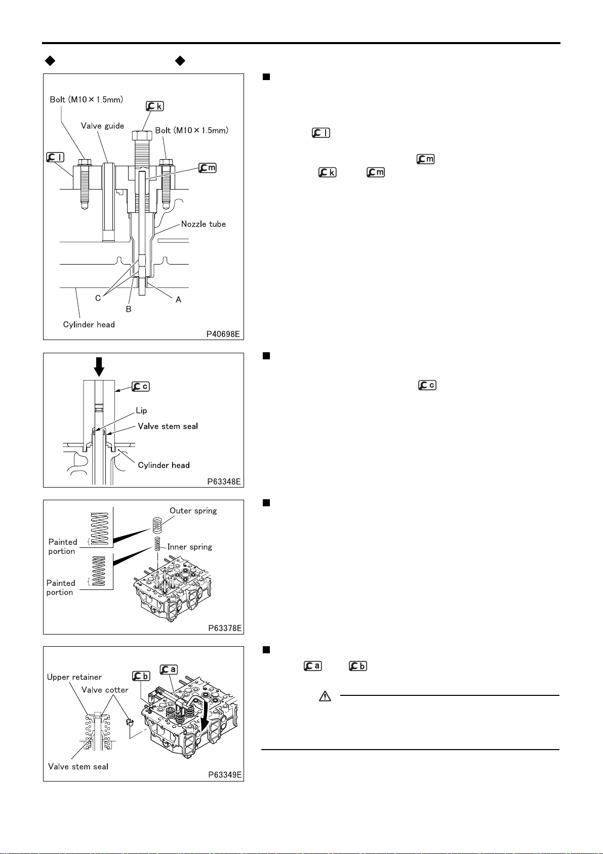
Installation procedure
Installation: Mitsubishi 6M70 Nozz
le tube
• Apply a sealant to the perimeter A of the tip of the nozzle tube.
• Push in the nozzle tube by hand until it contacts surface B of the
cylinder head.
• Tigh
ten with the bolt and press the nozzle tube onto sur-
face B of the cylinder head.
• Apply engine oil to section C of .
• Screw in until can be pulled out from the bottom of
the cylinder head.
• After installing the nozzle tube, be sure to perform a leak test to
check for airtightness.
Installation: Mitsubishi 6M70 Valve stem seal
• Apply engine oil to the lip of the valve stem seal.
• Install the valve stem seal until sits snugly on the cylinder
head.
• After assembly, check that its spring is not deformed or dam-
aged.
Installation: Mitsubishi 6M70 Valve spring
• Install the outer and inner valve springs onto the cylinder head
while facing them as shown in the illustration.
Installation: Mitsubishi 6M70 Valve cotter
• Using and , install the valve cotter while compressing
the valve spring(s) evenly.
CAUTION
• Do not compress the valve spring(s) too much, or the upper
retainer will contact the valve stem seal and damage will re-
sult.
CYLINDER HEAD AND VALVE MECHANISM

M E M O
11-53
11
11-54
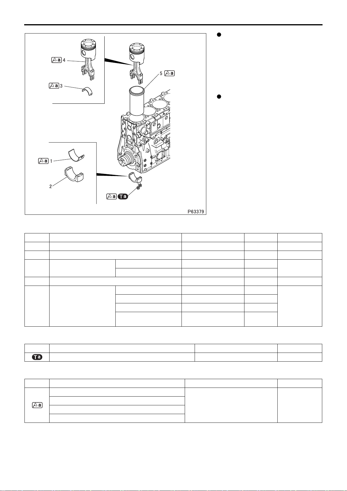
Disassembly sequence
1 Lower connecting rod bearing
2 Connecting rod cap
3 Upper connecting rod bearing
4 Piston and connecting rod
(See later section.)
5 Cylinder liner
Assembly sequence
Follow the disassembly sequence in re-
verse.
Service standards (Unit: mm)
Tightening torque (Unit: N·m {kgf·m})
Lubricant and/or sealant
Location Maintenance item Standard value Limit Remedy
– Piston protrusion from crankcase top surface –0.321 to –0.111 – Replace
– End play of connecting rod 0.2 to 0.5 1.0 Replace
1, 3 Connecting rod bearing
Oil clearance 0.06 to 0.122 0.25
Replace
Span when free – 90.5
4, 5 Piston and cylinder liner clearance 0.247 to 0.277 – Replace
5 Cylinder liner
Flange protrusion 0.01 to 0.07 –
Replace
Inner diameter φ135 to 135.03 φ135.25
Cylindricity 0.03 or less –
Difference in protrusion of
adjacent flange
0.04 or less –
Mark Parts to be tightened Tightening torque Remarks
Nut (connecting rod cap mounting) 49 {5} + 120° Wet
Mark Points of application Specified lubricant and/or sealant Quantity
Nut thread
Engine oil As required
Inside surface of connecting rod bearing
Outside periphery of cylinder liner
Outer periphery of piston
M
ITSUBISHI 6M70 PISTON, CONNECTING ROD AND
CYLINDER LINER
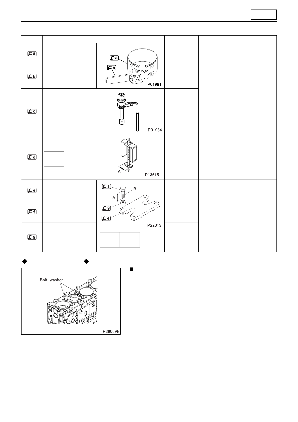
11
11-55
Special tools (Unit: mm)
Work before removal
Retaining of cylinder liners
• The cylinder liners may move up when the crankcase is turned
over, or the crankshaft is rotated after the pistons are installed.
To prevent this, retain the cylinder liners by holding their flanges
with bolts and washers.
Mark Tool name and shape Part No. Application
Piston guide clamp MH061667
Installation of piston and connecting
rod
Piston guide lever MH061658
Socket wrench MH061560
MH062194 Removal of cylinder liner
Adapter ME350054
Measurement of cylinder liner flange
protrusion and step height between
adjacent cylinder liners
Bolt MF130651
Washer MF450009
Cylinder liner extractor
A
φ134.5
AB
40 M16
× 2
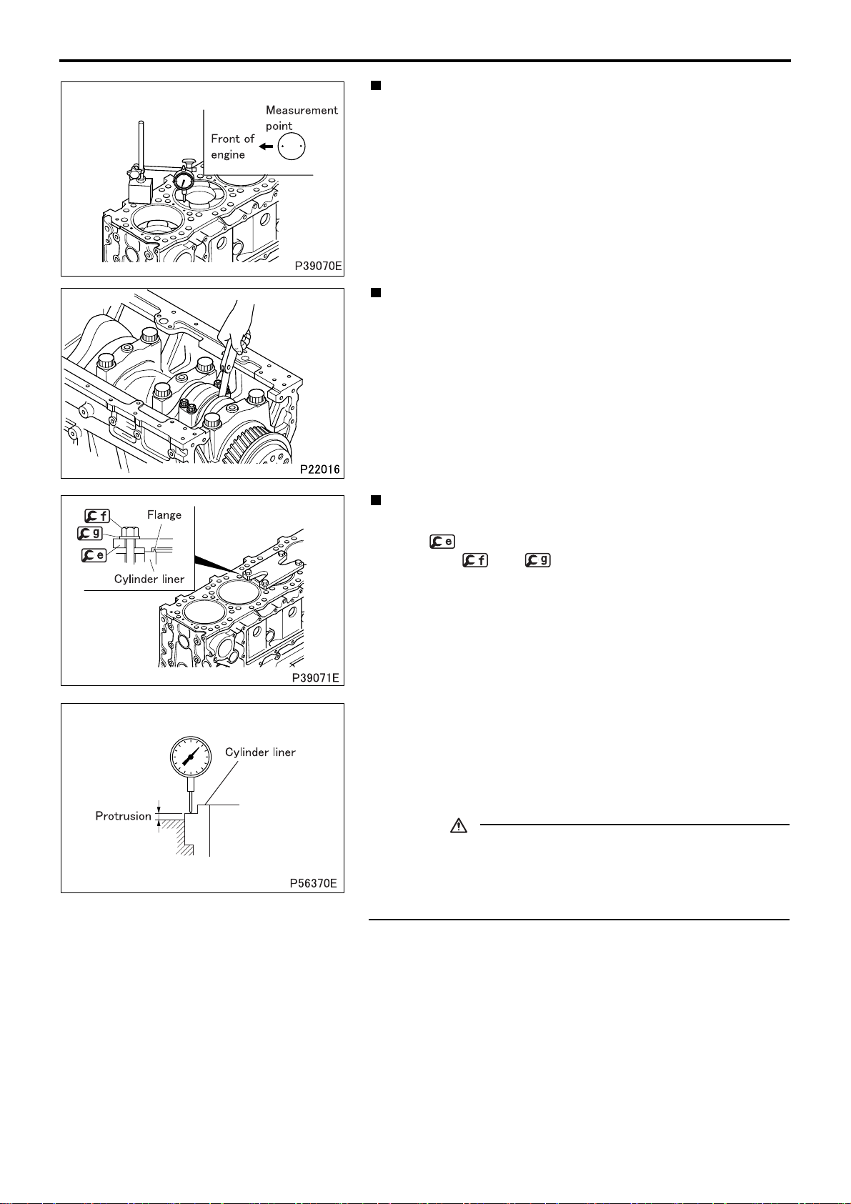
11-56
Inspection: Piston protrusion from crankcase top surface
• The amount of piston protrusion affects engine performance and
must therefore be inspected without fail.
• Set the piston at the top dead center.
• Make the measurement at the two measurement points on the
top face of the piston and calculate the average value.
• If the average value deviates from the standard value, check the
clearances between all relevant parts.
Inspection: Connecting rod end play
• Measure the end play for every connecting rod.
• If the measurement exceeds the limit, replace the defective
part(s).
Inspection: Cylinder liner flange protrusion and step height
between adjacent cylinder liners
• Install so that it does not run onto the cylinder liner flange
and tighten and to the torque of 49 N
·m {5 kgf·m}.
• Measure the cylinder liner flange protrusion.
• If the measurement deviates from the standard value, inspect
the installation and replace the defective part(s).
• If the difference in the adjacent flange protrusion deviates from
the standard value, replace the defective part(s) upon checking
the installed condition.
CAUTION
• If the cylinder liner flange protrusion is not within the speci-
fied value, the contact pressure of the cylinder head gasket
against the bore of the cylinder will not be high enough to
prevent gas leakage.
PISTON, CONNECTING ROD AND CYLINDER LINER
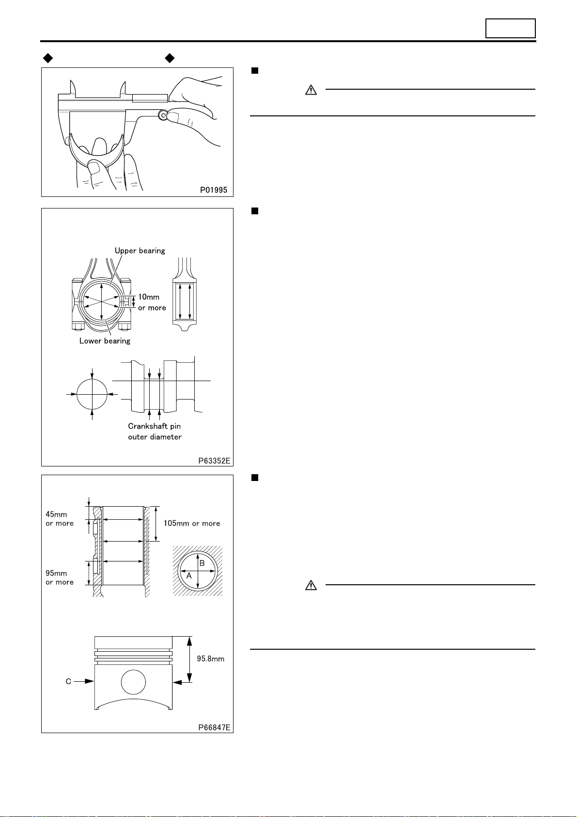
11
11-57
Inspection procedure
Inspection: Connecting rod bearing span when free
CAUTION
• Do not attempt to manually expand the bearings.
• If the measurement is less than the limit, replace the upper and
lower connecting rod bearings.
Inspection: Connecting rod bearing-to-crankshaft clearance
(oil clearance)
• Fit the lower bearing to the connecting rod cap and the upper
bearing to the connecting rod, then tighten the nut to a torque of
115 N
·m {12 kgf·m}.
• Measure the inner diameter of the bearing and the outer diame-
ter of the crankshaft pin.
• If the clearance exceeds the limit, replace the defective part(s).
• If a bearing has to be replaced with an undersized one, machine
the crankshaft pin to the specified undersize diameter.
(See “CRANKSHAFT AND CRANKCASE”.)
Inspection: Mitsubishi 6M70 Piston and cylinder liner clearance
• If the value calculated from the measurement deviates from the
standard value, replace the defective part(s).
A: Measuring point on the crankcase (in direction of the crank-
case axis).
B: Measuring point on the crankcase (vertical to the crankcase
axis).
C: Measuring point on the piston (vertical to the piston pin hole).
CAUTION
• Because the cylinder liner is a thin-walled liner, the boring
process cannot be preformed on an oversized liner. Do not
remove the cylinder liner except for replacement to prevent
deformation.
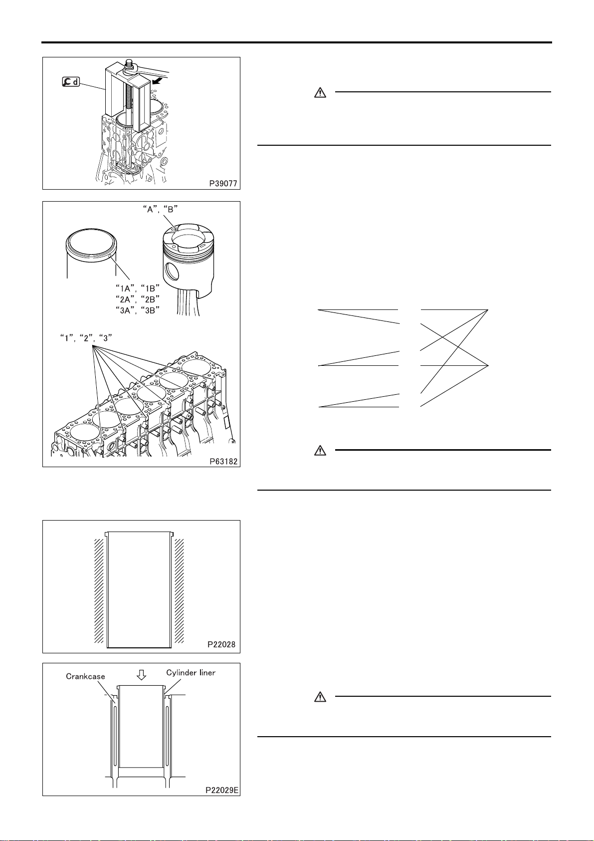
11-58
Replacement of cylinder liner
[Removal]
CAUTION
• If the cylinder liners will need to be reused for some reason
or other, make alignment marks to ensure correct reassem-
bly.
[Installation]
• When replacing the cylinder liner, use the size mark on the
crankcase and the size mark on the piston to select the appro-
priate size of the cylinder liner.
CAUTION
• Using a piston with the size mark different from the size
mark of cylinder liner can lead to engine seizure.
• Apply a thin coat of engine oil onto the outer periphery (hatched
area) of the cylinder liner.
• While pushing the
cylinder liner evenly with hands, gently insert
the cylinder liner into the crankcase.
CAUTION
• Cylinder liners are thinly structured. Therefore, they must
be handled with extreme care.
Size mark
on crankcase
Size mark
on cylinder liner
Size mark
on piston
“1”
“3”
“2A”
“2” “2B”
“1B”
“3A”
“A”“1A”
“3B”
“B”
PISTON, CONNECTING ROD AND CYLINDER LINER
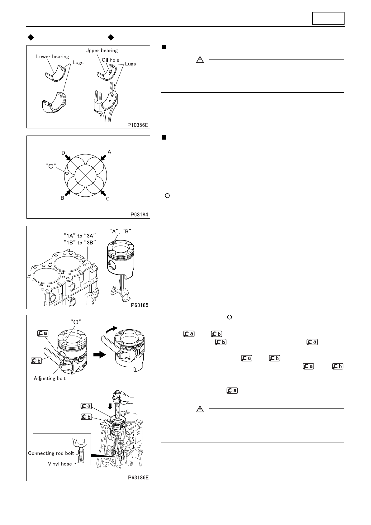
11
11-59
Installation procedure
Installation: Connecting rod bearings
CAUTION
• Do not reverse the positions of the lower bearing and the
upper bearing (with oil hole) when installing, as this may
cause seizure in the engine.
Installation: Piston and connecting rod
• Check that the piston ring end gaps are in their correct positions.
A: 1st compression ring gap
B: 2nd compression ring gap
C: Oil ring gap
D: Oil ring expander spring gap
“ ”: Front mark on piston
• Ensure that the size mark (“A”, “B”) on the piston is the same as
that on the cylinder liner.
• Face the front mark “ ” of the piston toward the front of the en-
gine.
• With and installed around the piston skirt, tighten the
adjusting bolt of until the inside diameter of matches
the outside diameter of the piston skirt.
• After adjustment, remove and from the piston. Apply
engine oil to the following areas. Then, install and
over the rings of the piston.
• Outer periphery of piston
• Inner periphery of
• Inner periphery of cylinder liner
CAUTION
• Cover the connecting rod bolt with a vinyl hose to prevent
the connecting rod bolt from damaging the inside surface
of the cylinder and crankshaft.
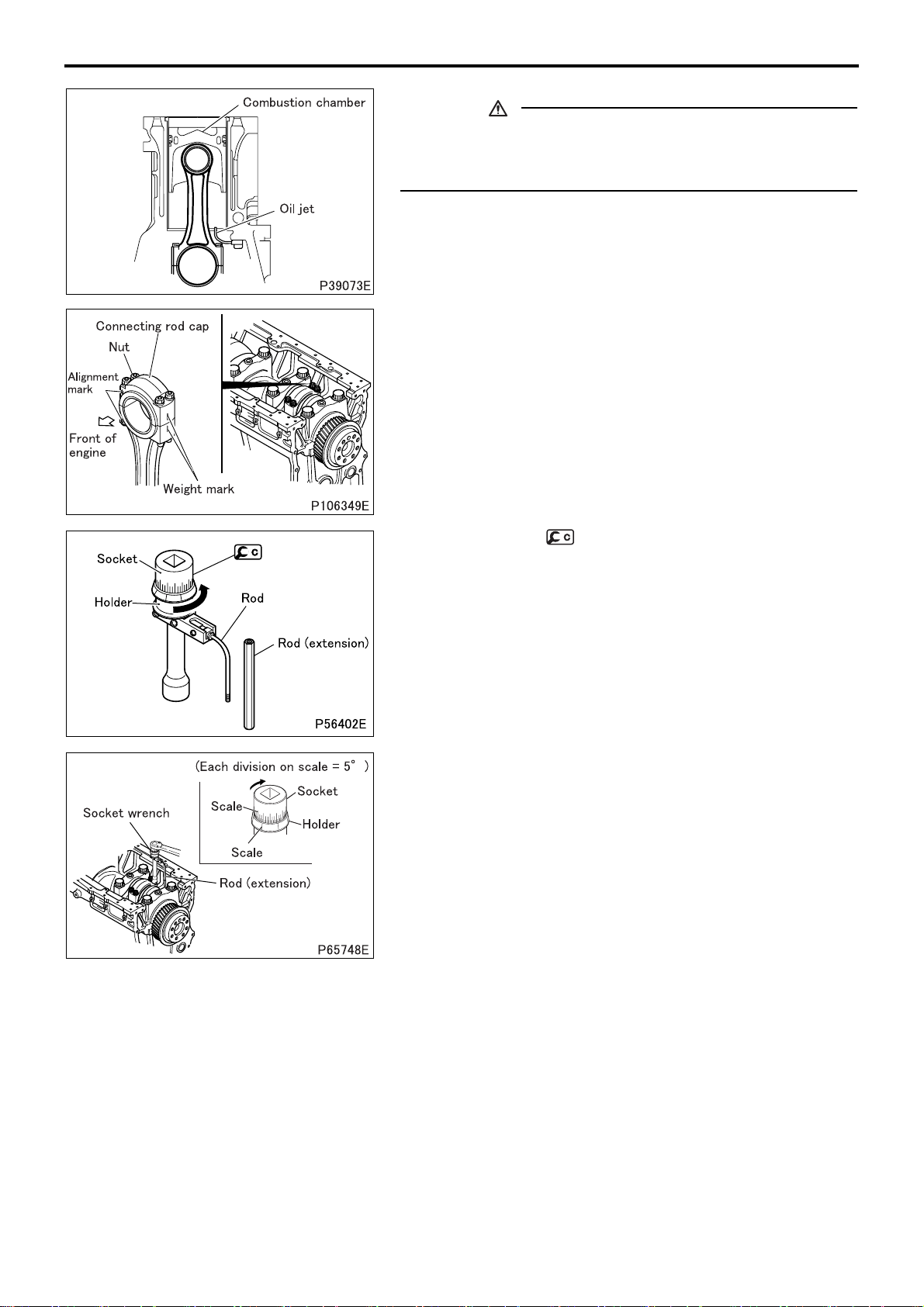
11-60
CAUTION
• Be careful not to scratch or damage head of the piston (a
part of the combustion chamber).
• Make sure that the connecting rod does not hit oil jet.
• After installing the piston and connecting rod, install the connect-
ing rod cap onto the connecting rod, ensuring that the their align-
ment marks (projection) are aligned with the weight mark. Then,
tighten the nut to the torque of 49 N
·m {5 kgf·m}.
• Further tighten the bolts in the following procedure.
• Turn the holder of counterclockwise to pretension the inter-
nal spring.
• Set
the tool such that the rod (extension) is pressed against the
crankshaft by the force of the spring.
• Align any line on the holder scale with any line on the socket
scale. (This will be used as the reference point = 0°.)
• From the reference point, turn the socket by 120° in the direction
shown. Each division on the socket scale represents 5°.
• After assembly of the connecting rod cap, perform the following
test.
• End play of connecting rod
• Piston protrusion
PISTON, CONNECTING ROD AND CYLINDER LINER
M
itsubishi 6M70 Engine Parts contact:
email: [email protected]
Phone: 269 673 1638

M E M O
11-61
11
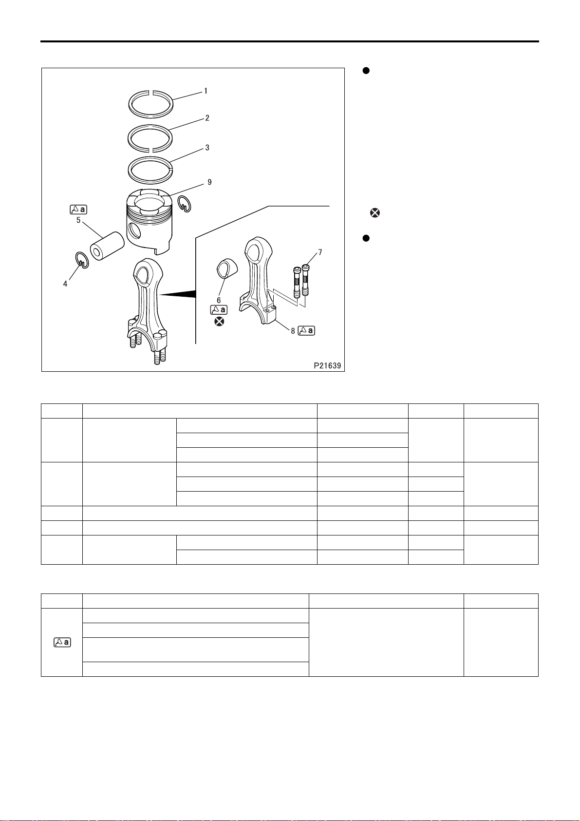
11-62
Mitsubishi 6M70 Piston and Connecting Rod
Disassembly sequence
1 1st compression ring
2 2nd compression ring
3 Oil ring
4 Snap ring
5 Piston pin
6 Connecting rod bushing
7 Connecting rod bolt
8 Connecting rod
9 Piston
: Non-reusable parts
Assembly sequence
Follow the disassembly sequence in re-
verse.
M
itsubishi 6M70 Service standards (Unit: mm)
Lubricant and/or sealant
Location Maintenance item Standard value Limit Remedy
1 to 3 Piston ring end gap
1st compression ring 0.4 to 0.55
1.5 Replace2nd compression ring 0.5 to 0.65
Oil ring 0.4 to 0.6
1 to 3, 9
Clearance between
piston ring and piston
ring groove
1st compression ring 0.015 to 0.06 0.15
Replace2nd compression ring 0.085 to 0.125 0.25
Oil ring 0.025 to 0.065 0.15
5, 6 Clearance between piston pin and connecting rod bushing 0.02 to 0.055 0.1 Replace
5, 9 Clearance between piston pin and piston 0.004 to 0.022 0.1 Replace
8 Connecting rod
Bend – 0.05
Replace
Twist – 0.1
Mark Points of application Specified lubricant and/or sealant Quantity
Outer periphery of piston pin
Engine oil As required
Outer periphery of connecting rod bushing
Connecting rod bushing mounting surface of connecting
rod
Connecting rod bolt mounting hole
PISTON, CONNECTING ROD AND CYLINDER LINER
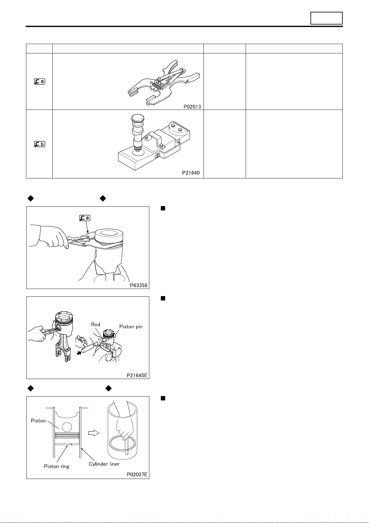
11
11-63
Special tools
Removal procedure
Removal: Piston ring
Removal: Piston pin
• Remove the piston pin by striking it with a rod and hammer.
• If the piston pin is difficult to remove, first heat the piston in hot
water or with a piston heater.
Inspection procedure
Inspection: Mitsubishi 6M70 Piston ring end gap
• Using the crown of a piston, push the piston ring horizontally into
a cylinder in the crankcase until it reaches the lower part of the
cylinder liner, where there is relatively small wear.
• Taking care not to move the piston ring, measure the end gap.
• If the measurement exceeds the limit, replace all the piston rings
as a set.
Mark Tool name and shape Part No. Application
Piston ring tool 31191-02900
Removal and installation of piston
rings
Connecting rod bushing
puller kit
MH062185
Removal and installation of connect-
ing rod bushings
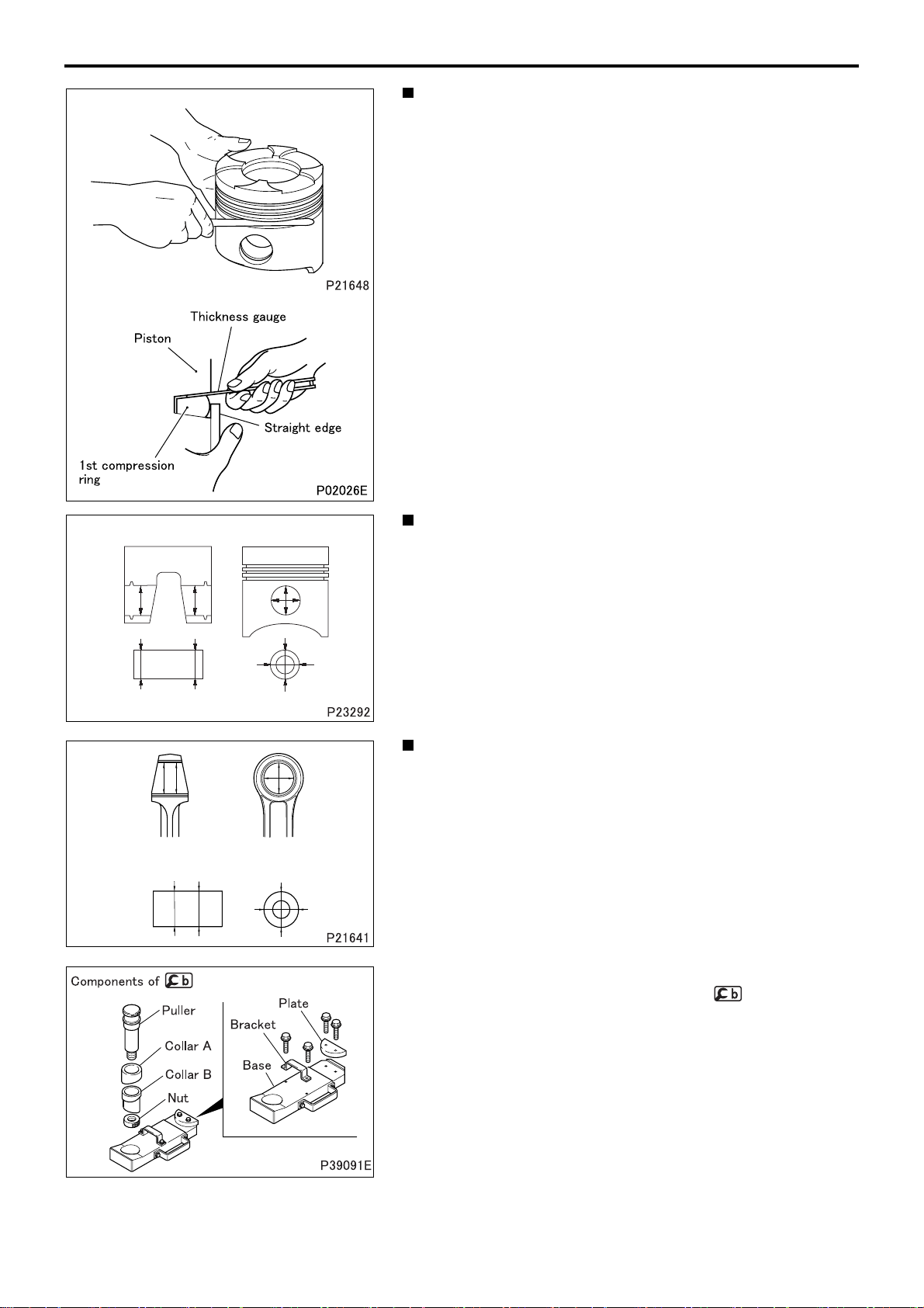
11-64
Inspection: Mitsubishi 6M70 Clearance between piston
ring and piston ring groove
• Remove any carbon deposits from the ring groove in the piston.
• Measure the side clearance of each ring around the piston’s en-
tire periphery of the ring groove.
• If the measurement exceeds the limit, replace the defective
part(s). If any of the piston rings is defective, replace all the pis-
ton rings as a set.
• The clearance of the 1st compression ring must be measured
using a thickness gauge while holding the ring against the piston
ring groove with a straight edge.
Inspection: Clearance between piston pin and piston
• If the measurement exceeds the limit, replace the defective
part(s).
Inspection: Mitsubishi 6M70 Clearance between piston
pin and connecting rod bushing
• If the measurement exceeds the limit, replace the bushing.
Replacement of connecting rod bushing
• Replace the connecting rod bushing using .
PISTON, CONNECTING ROD AND CYLINDER LINER
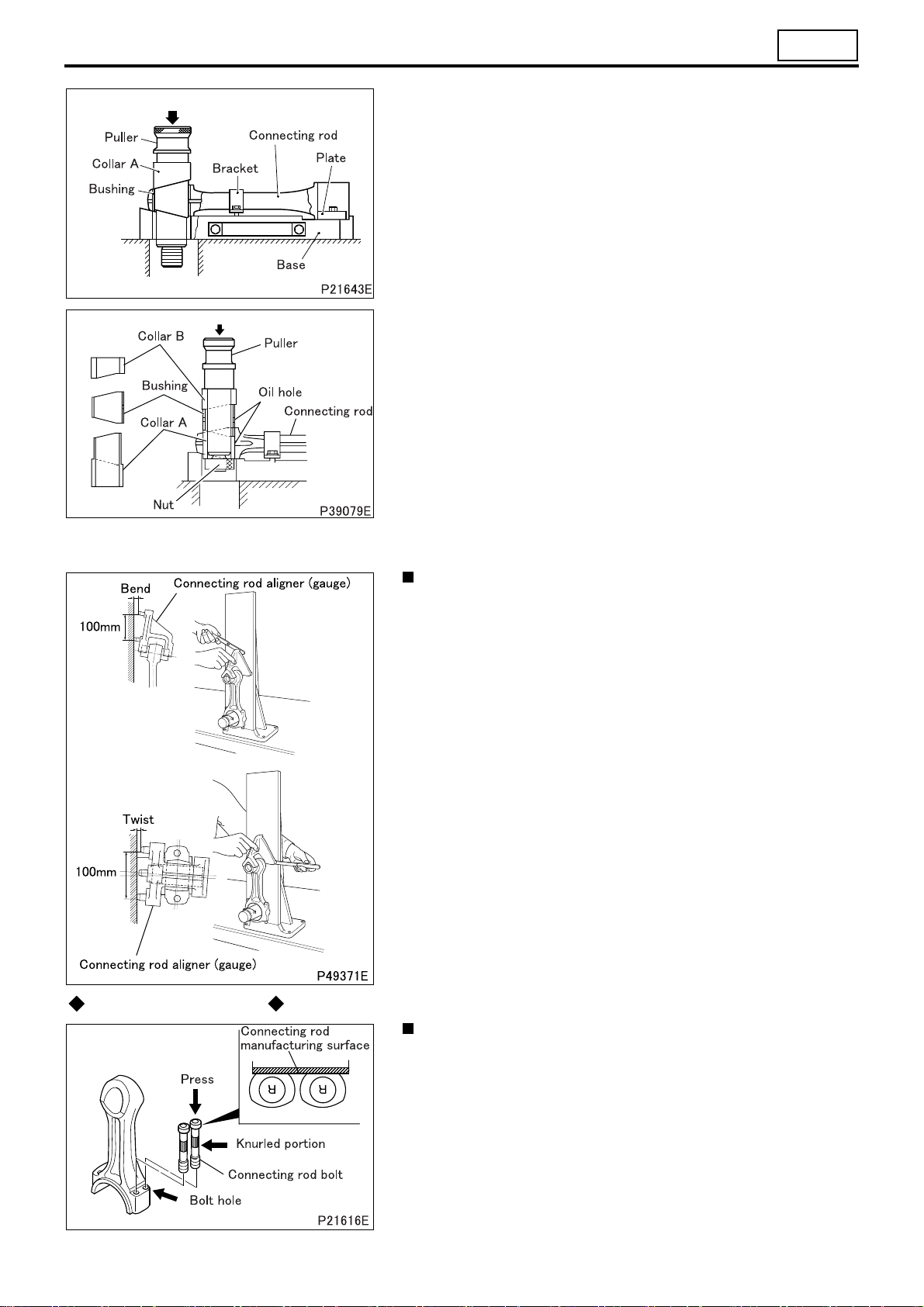
11
11-65
[Removal]
• If the upper connecting rod bearing is installed on the big end of
the connecting rod, remove the bearing.
• Secure the connecting rod to the base with a bracket and plate.
• Set collar A on the puller in the direction shown in the illustration
and gradually remove the bushing with a press load of approxi-
mately 49 kN {5000 kgf}.
[Installation]
• Apply engine oil to the outer periphery of the connecting rod
bushing and the bushing fitting surface of the connecting rod.
• Fit collar B, the bushing, and collar A over the puller in the direc-
tion shown in the illustration and lock this arrangement together
with the nut.
• Align the oil holes in the bushing and the connecting rod. Then,
use a press to slowly apply a pressure of approximately 49 kN
{5,000 kgf} to the puller until the bushing is forced into place.
• After assembly, measure the clearance again.
• If the measurement is less than the standard value, ream the
bushing.
Inspection: Connecting rod bend and twist
• Mount the connecting rod on the connecting rod aligner. Also
mount the connecting rod bearings, piston pin, and connecting
rod cap to create the same conditions as are expected when the
connecting rod is mounted on a crankshaft. Tighten the nuts of
the connecting rod cap to a torque of 115 N
·m {12 kgf·m}.
• Measure the extent of bend and twist in the connecting rod.
• If either measurement exceeds the limit, replace the connecting
rod.
Installation procedure
Installation: Mitsubishi 6M70 Connecting rod bolt
• Make sure that bolt holes of the connecting rod are free of flaws
and burrs.
• Apply engine oil to the knurled portion of the connecting rod bolt
and press fit it in the illustrated direction with the maximum press
load of 5880 N {600 kgf}.
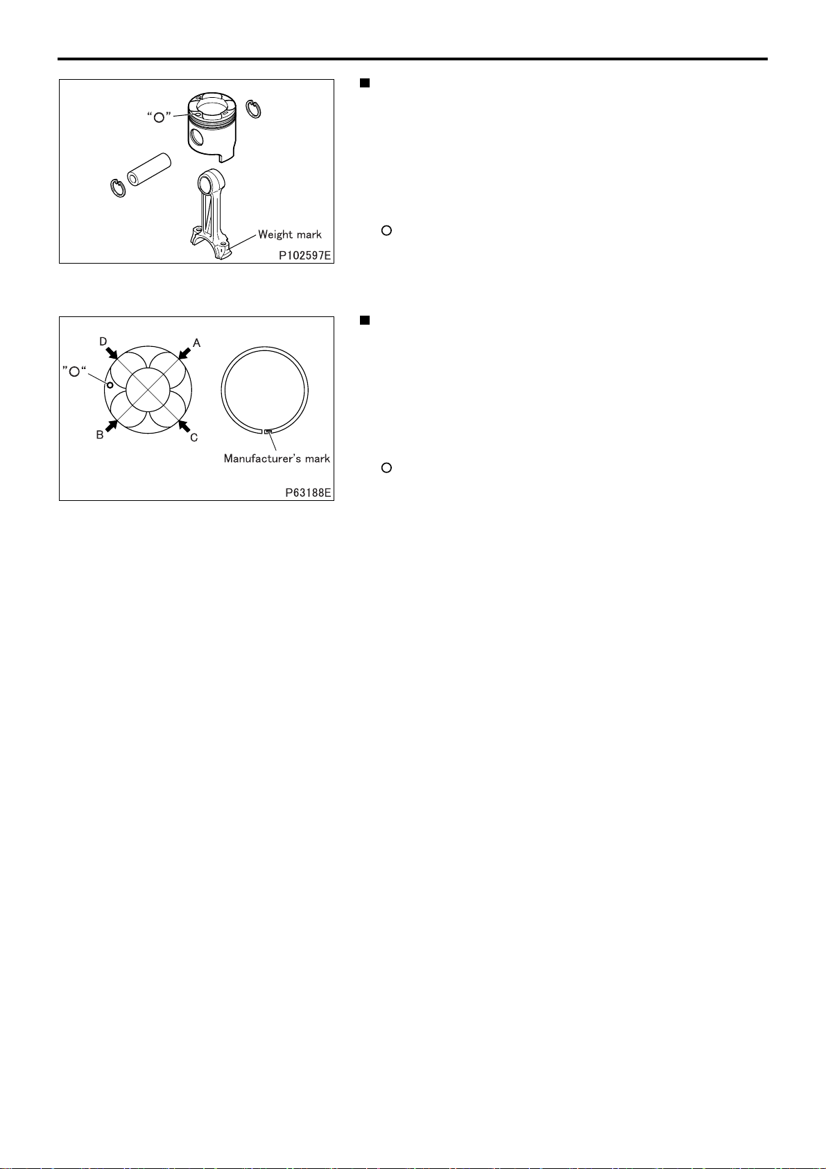
11-66
Installation: Mitsubishi 6M70 Piston and connecting rod
• When the piston and connecting rods are replaced, install each
part as follows;
• Select all the connecting rods with the same weight mark on the
same engine (‘‘A to H’’, ‘‘J to M’’).
• Apply engine oil to the piston pin, and assemble the piston and
connecting rod with their marks facing in the illustrated direc-
tions.
“ ”:Front mark
• If the piston pin is difficult to insert, first heat the piston in hot wa-
ter or with a piston heater. Then, install the piston.
Installation: Mitsubishi 6M70 Piston rings
• With the manufacturer’s marks (found near the piston ring end
gaps) facing up, install the piston rings so that the end gap of
each ring is positioned as shown in the illustration.
A: 1st compression ring end gap
B: 2nd compression ring end gap
C: Oil ring end gap
D: Oil ring expander spring end gap
“ ”: Front mark on piston
The manufacturer’s marks are present only on the 1st and 2nd
compression rings.
PISTON, CONNECTING ROD AND CYLINDER LINER

M E M O
11-67
11
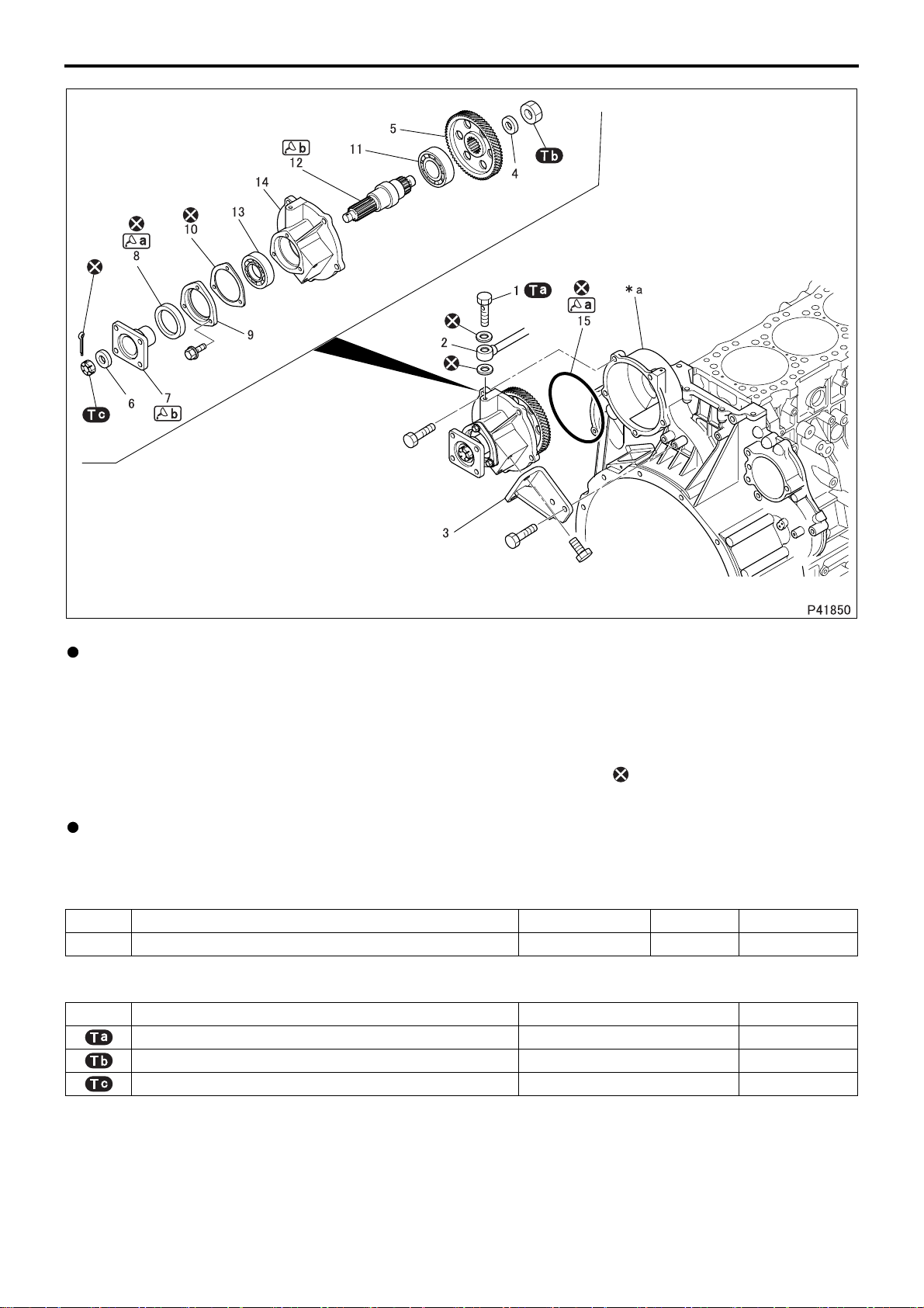
11-68
Disassembly sequence
Assembly sequence
Follow the disassembly sequence in reverse.
Service standards (Unit: mm)
Tightening torque (Unit: N·m {kgf·m})
Location Maintenance item Standard value Limit Remedy
– Total backlash of gears 0.19 to 0.62 0.8 Replace
Mark Parts to be tightened Tightening torque Remarks
Eyebolt 21 {2.1} –
Nut (PTO gear installation) 220 {22} –
Nut (flange installation) 178 {17.8} –
1 Eyebolt
2 Oil pipe
3 PTO bracket
4 Washer
5 PTO gear
6 Washer
7 Flange
8 Oil seal
9 Cover
10 Gasket
11 Roller bearing
12 PTO shaft
13 Ball bearing
14 PTO head
15 O-ring
*
a: Flywheel housing
: Non-reusable parts
FLYWHEEL PTO <WITH FLYWHEEL PTO>
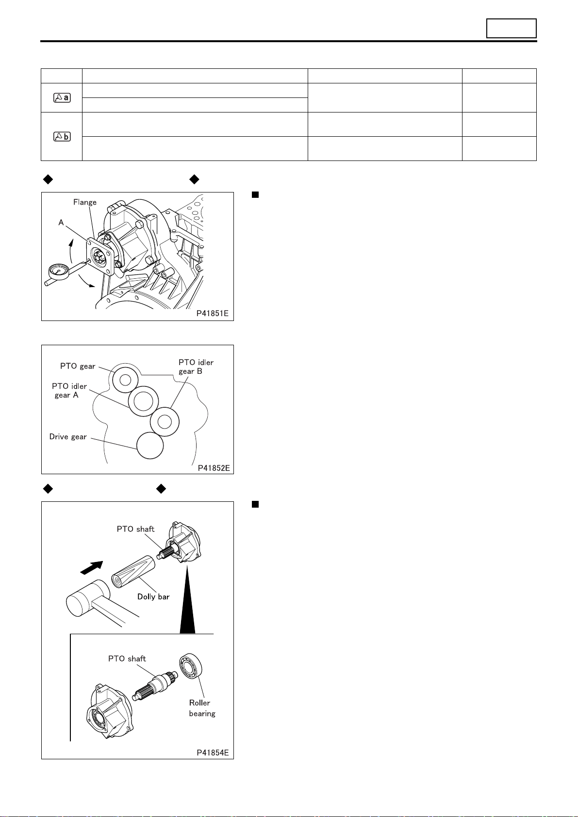
11
11-69
Lubricant and/or sealant
Inspection before removal
Inspection: Total backlash of gears
• “Total backlash of gears” is the gear backlash produced when
the PTO gear, PTO idler gear A, PTO idler gear B and drive gear
are all in mesh with each other.
• Measure the total backlash of gears by inserting a lever type dial
gauge into the threaded holes A in the flange of the PTO head
assembly.
• If the measurement is out of specification, check each gear for
wear and replace if necessary.
• Check the PTO idler gear A, PTO idler gear B and drive gear for
wear. (See TIMING GEARS <WITH FLYWHEEL PTO>.)
Removal procedure
Removal: Roller bearing and PTO shaft
• Remove the roller bearing and PTO shaft in the direction shown
in the illustration.
Mark Points of application Specified lubricant and/or sealant Quantity
O-ring
Engine oil As required
Oil seal lip
Sliding contact surfaces of flange and oil seal
Multipurpose grease
[NLGI No.2 (Ca soap)]
As required
Fitting surfaces of flange and PTO shaft
Multipurpose grease
[NLGI No.2 (Ca soap)]
As required
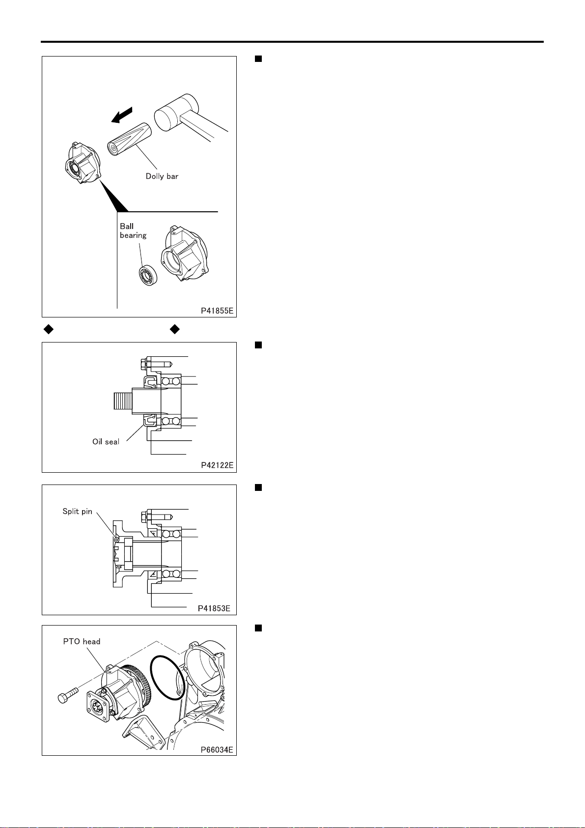
11-70
Removal: Ball bearing
• Remove the ball bearing in the direction shown in the illustration.
Installation procedure
Installation: Oil seal
• Fit the oil seal oriented as shown in the illustration.
Installation: Split pin
• After fitting, bend the split pin in the illustrated direction.
Installation: PTO head
• Make sure that the PTO shaft turns lightly by hand before install-
ing the PTO head onto the flywheel housing.
FLYWHEEL PTO <WITH FLYWHEEL PTO>

M E M O
11-71
11
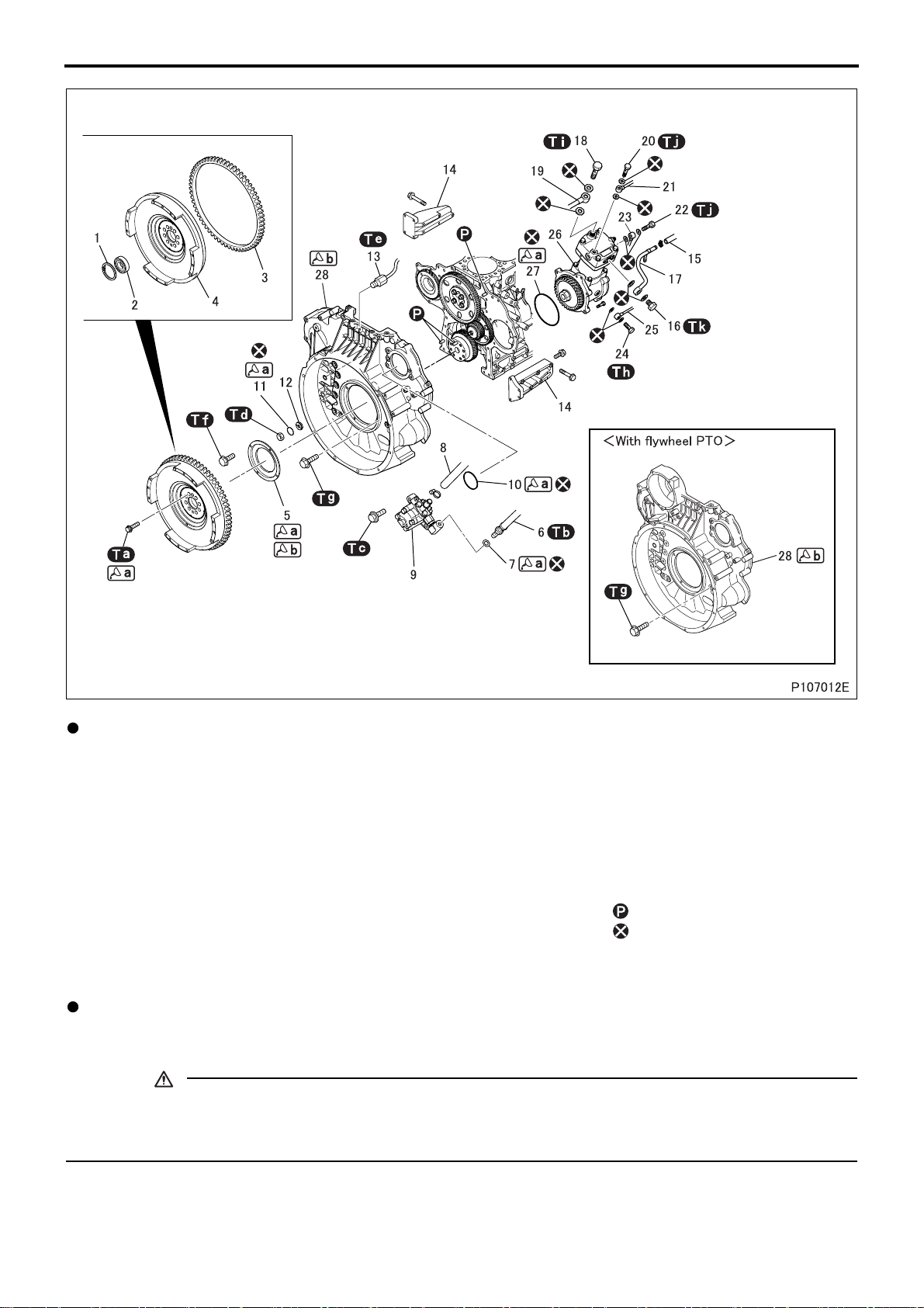
11-72
Disassembly sequence
Assembly sequence
Follow the disassembly sequence in reverse.
CAUTION
• The flywheel mounting bolt is tightened within the plastic region. The number of punch marks indicates
the number of times the bolt has been tightened. If there are 3 punch marks (tightened 3 times in the
past), replace the bolt.
1 Snap ring
2 Pilot bearing
3 Ring gear
4 Flywheel
5 Rear oil seal
6 Power steering oil hose
7 O-ring
8 Suction hose
9 Power steering oil pump
(See Gr37.)
10 O-ring
11 O-ring
12 Collar
13 Engine speed sensor
14 Stiffener
15 Air suction hose
16 Eyebolt
17 Air suction pipe
18 Eyebolt
19 Air outlet pipe
20 Eyebolt
21 Water outlet pipe
22 Eyebolt
23 Water inlet pipe
24 Eyebolt
25 Oil pipe
26 Air compressor
27 O-ring
28 Flywheel housing
: Locating pin
: Non-reusable parts
FLYWHEEL
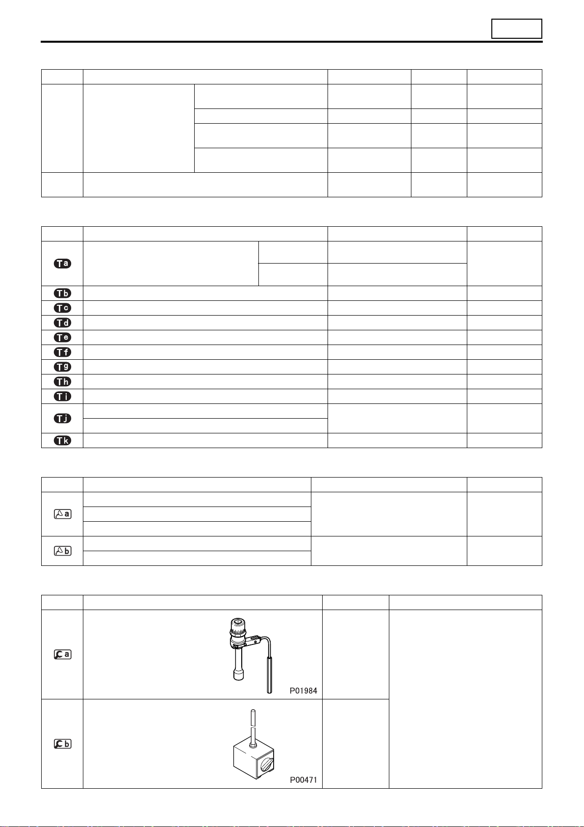
11
11-73
Service standards (Unit: mm)
Tightening torque (Unit: N·m {kgf·m})
Lubricant and/or sealant
Special tools
Location Maintenance item Standard value Limit Remedy
4 Flywheel
Friction surface distortion 0.05 0.2
Rectify or
replace
Friction surface height 48 ± 0.2 49.5 Replace
Friction surface runout
(when fitted)
–0.2
Rectify or
replace
Friction surface parallelism 0.1 or less –
Rectify or
replace
28
Eccentricity of flywheel housing measured at spigot joint sec-
tion (when fitted)
–0.2
Inspect or
replace
Mark Parts to be tightened Tightening torque Remarks
Bolt (flywheel mounting)
Without PTO 100 {10} + 90°
• Wet
• Can be reused
up to 3 times
With PTO 100 {10} + 150°
Power steering oil hose 68 {7.0} –
Bolt (power steering oil pump mounting) 74 {7.5} –
Nut (collar mounting) 100 {10} –
Engine speed sensor 25 {2.5} –
Bolt (rear oil seal mounting) 12 {1.2} –
Bolt (flywheel housing mounting) 80 {8.0} –
Eyebolt (oil pipe mounting) 21 {2.1} –
Eyebolt (air outlet pipe mounting) 100 {10} –
Eyebolt (water inlet pipe mounting)
50 {5.1} –
Eyebolt (water outlet pipe mounting)
Eyebolt (air suction pipe mounting) 155 {16} –
Mark Points of application Specified lubricant and/or sealant Quantity
Thread of bolts
Engine oil As requiredO-ring
Rear oil seal lip
Rear oil seal surface to be mated with flywheel housing
ThreeBond 1207C As required
Engine mounting surface of flywheel housing
Mark Tool name and shape Part No. Application
Socket wrench ME350193
Installation of flywheel
Magnet base MH062356
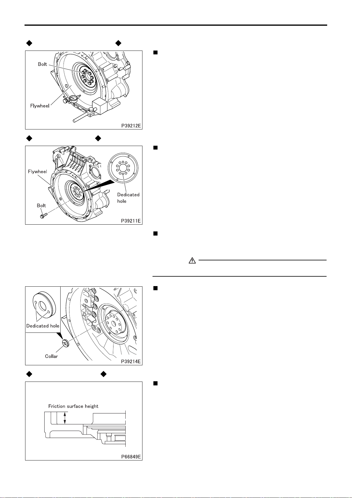
11-74
Inspection before removal
Inspection: Flywheel friction surface runout when fitted
• If the measurement exceeds the limit, check if the bolts are cor-
rectly tightened as well as the crankshaft mounting surface. Cor-
rect or replace the flywheel as required.
Removal procedure
Removal: Flywheel
• To remove the flywheel, use bolts inserted into the dedicated
holes in the flywheel.
Removal: Ring gear
• Heat the ring gear evenly with a gas burner or the like until it
reaches approximately 200°C, then remove it from the flywheel.
WARNING
• You may burn yourself if you touch the heated ring gear.
Removal: Collar
• Install bolts (M4 x 0.7 mm) into the dedicated holes in the collar,
and pull the bolts to remove the collar.
Inspection procedure
Inspection: Flywheel
(1) Friction surface height
• If the measurement exceeds the limit, replace the flywheel.
FLYWHEEL
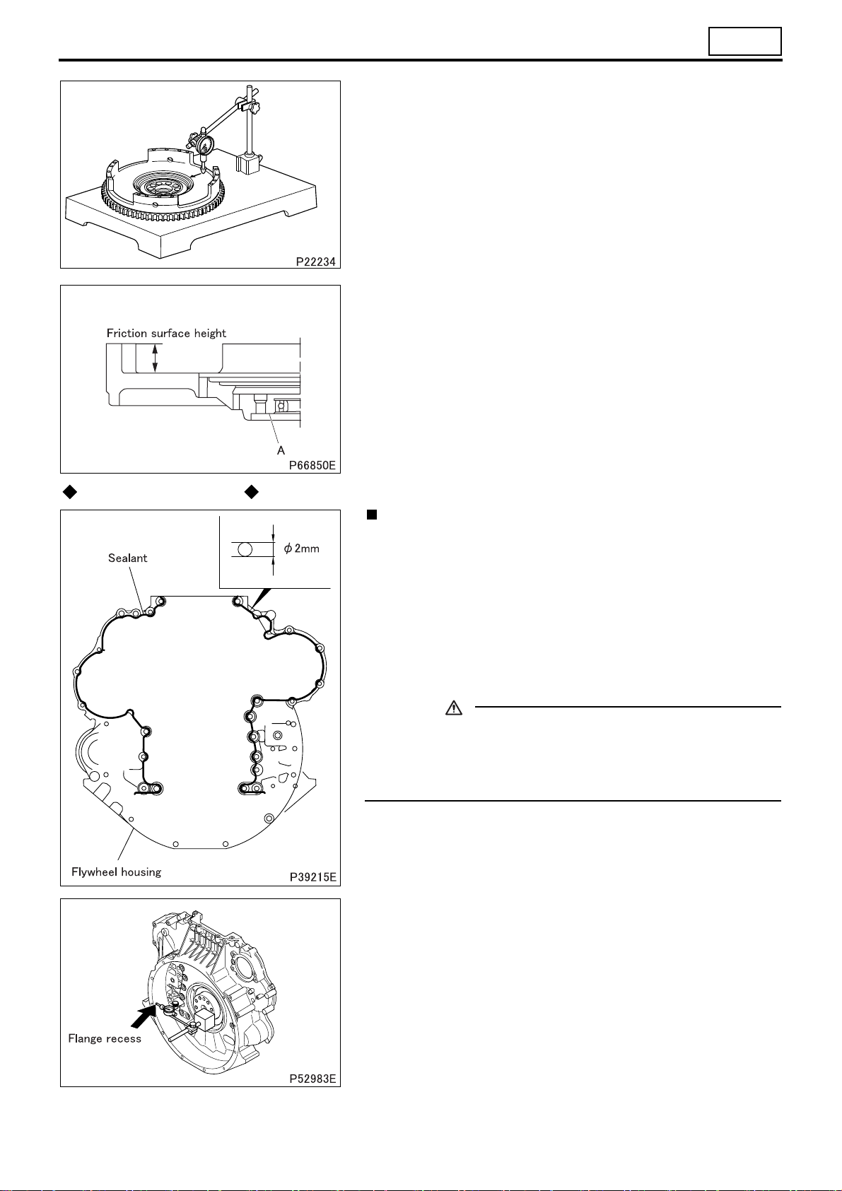
11
11-75
(2) Friction surface distortion
• If the measurement exceeds the limit, rectify or replace the fly-
wheel.
• If the ring gear is evidently defective, replace the ring gear be-
fore inspecting the friction surface for distortion.
Rectification of friction surface
• Rectify the friction surface so that its height is not above the
specified limit, and it is parallel with surface A within specifica-
tion.
Installation procedure
Installation: Flywheel housing
[Installation]
• Clean the flywheel housing surface where sealant is to be ap-
plied.
• Apply an even and continuous bead of sealant onto the flywheel
housing surface where the crankcase is to be mounted.
• Within three minutes following the application, install the fly-
wheel housing onto the crankcase. When installing the flywheel
housing, take care not to spread the sealant beyond the applica-
tion area.
CAUTION
• Do not start the engine at least for an hour after the flywheel
housing has been installed.
• If the flywheel housing mounting bolts are subsequently
loosened, be sure to apply sealant again upon reassembly.
[Inspection]
• While turning the crankshaft, measure the flywheel housing for
any eccentricity at the location indicated in the illustration.
• If the eccentricity exceeds the limit, reassemble the flywheel.
• If the eccentricity still exceeds the limit after reassembly, replace
the defective part(s).
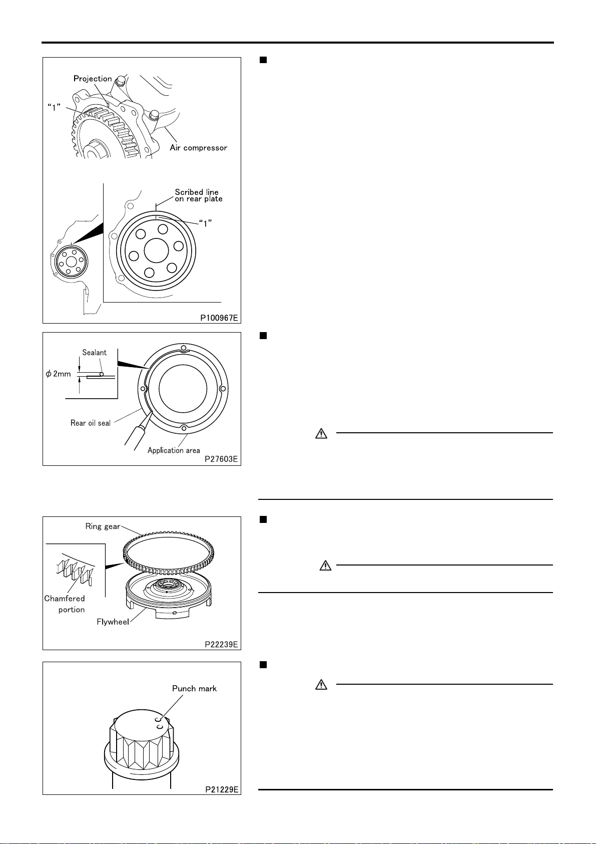
11-76
Installation: Air compressor
• Set the No. 1 cylinder piston at the top dead center of the com-
pression stroke.
• Align the stamped mark “1” on the air compressor gear with the
projection on the air compressor.
• While keeping this condition, align the stamped mark “1” with the
scribed line on the rear plate and install the air compressor to
the flywheel housing.
Installation: Rear oil seal
• Clean the rear oil seal surface where sealant is to be applied.
• Apply an even and continuous bead of sealant on the rear oil
seal as shown in the illustration.
• Install the rear oil seal onto the flywheel housing within 3 min-
utes following the application of the sealant. Be careful not to
dislodge the sealant.
CAUTION
• Do not start the engine at least for an hour after the rear oil
seal has been installed.
• If the rear oil seal mounting bolts are subsequently loos-
ened, be sure to apply sealant again upon reassembly.
Installation: Ring gear
• Heat the ring gear evenly with a gas burner or the like until it
reaches approximately 200°C.
WARNING
• You may burn yourself if you touch the heated ring gear.
• Fit the ring gear with the side having non-chamfered portions to-
ward the flywheel.
Installation: Flywheel
CAUTION
• Before installing a bolt, check the number of punch marks
on the bolt head. (Bolts with up to two punch marks can be
reused.)
The number of punch marks indicates the number of times
the bolt has been tightened in the past within the plastic re-
gion. If there are three punch marks (tightened three times
in the past), replace the bolt.
FLYWHEEL
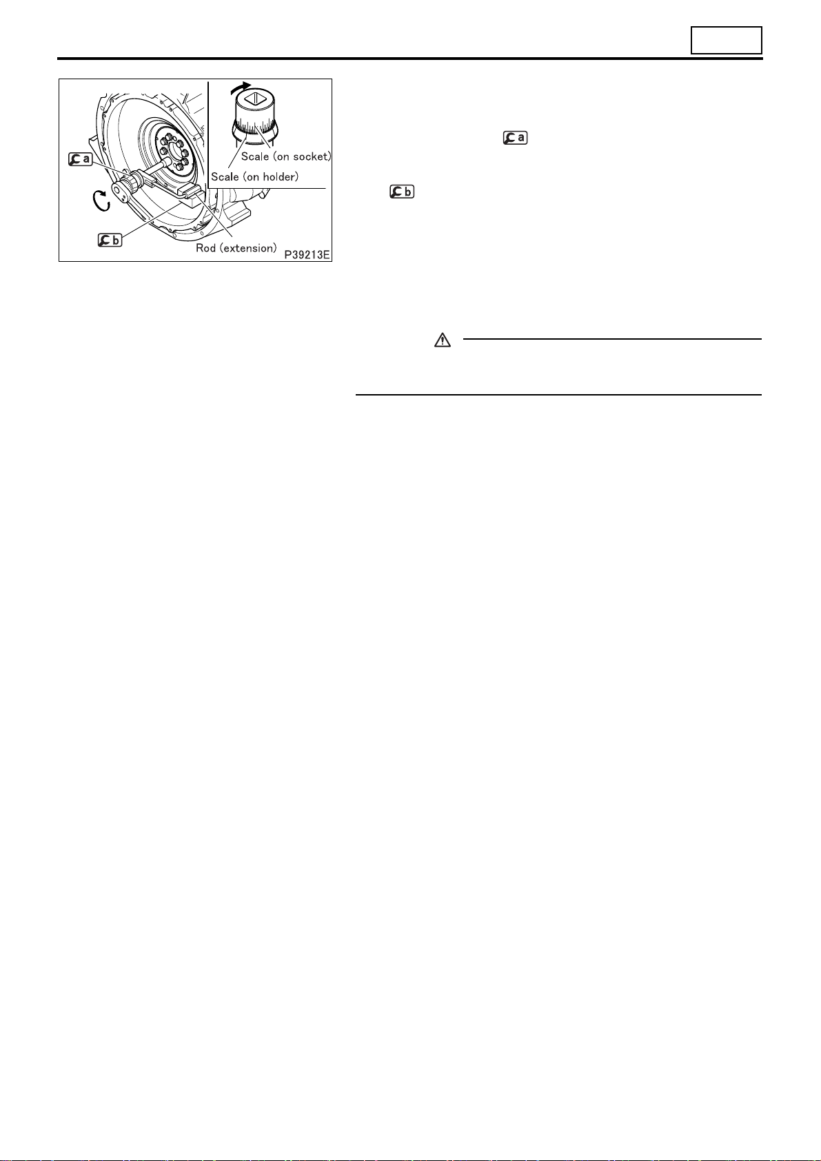
11
11-77
• Tighten the flywheel mounting bolts to a torque of 100 N·m {10
kgf·m}.
• Further tighten the bolts in the following procedure.
• Turn the holder
of
counterclockwise to preload the built-
in spring.
• Set the tool such that the rod (extension) is pressed against
by the force of the spring.
• Align any line on the holder scale with any line on the socket
scale. (This will be used as the reference point = 0°.)
• From the reference point, turn the socket by 90° <Without fly-
wheel PTO>, 150° <With flywheel PTO> clockwise. Each divi-
sion on the socket scale represents 5°.
• After tightening the bolt within the plastic region, make a
punch mark on the bolt head for subsequent identification.
CAUTION
• The bolts should be tightened within the plastic region.
Never tighten them further than the specified angle.
Mitsubishi 6M70 Engine Par
ts contact:
email: [email protected]
Phone: 269 673 1638
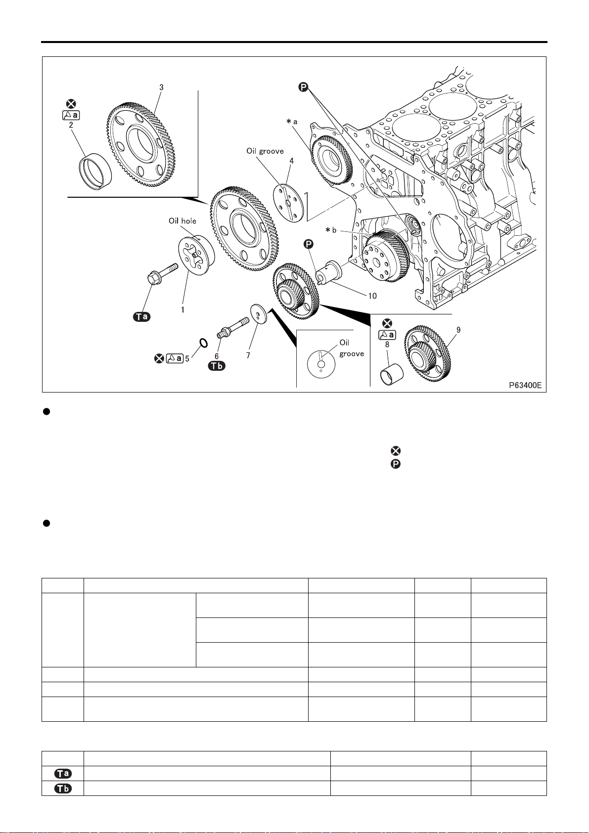
11-78
Disassembly sequence
Assembly sequence
Follow the disassembly sequence in reverse.
Service standards (Unit: mm)
Tightening torque (Unit: N·m {kgf·m})
Location Maintenance item Standard value Limit Remedy
– Backlash between gears
Idler gear C and supply
pump gear
0.096 to 0.198 0.35 Replace
Idler gear C and idler gear
A, B
0.089 to 0.181 0.35 Replace
Idler gear A, B and crank-
shaft gear
0.076 to 0.196 0.35 Replace
1, 2 Clearance between idler shaft C and idler gear bushing 0.036 to 0.08 0.2 Replace
3, 9 Idler gear end play 0.1 to 0.2 0.4 Replace
8, 10
Clearance between idler shaft A, B and idler gear bush-
ing
0.025 to 0.066 0.2 Replace
Mark Parts to be tightened Tightening torque Remarks
Bolt (idler gear C mounting) 80 {8.0} –
Idler shaft bolt (idler gear A, B mounting) 155 {16} –
1 Idler shaft C
2 Idler gear bushing
3 Idler gear C
4 Thrust plate C
5 O-ring
6 Idler shaft bolt
7 Thrust plate A, B
8 Idler gear bushing
9 Idler gear A, B
10 Idler shaft A, B
*
a: Supply pump gear
*
b: Crankshaft gear
: Non-reusable parts
: Locating pin
M
ITSUBISHI 6M70 TIMING GEARS
<WITHOUT FLYWHEEL PTO>
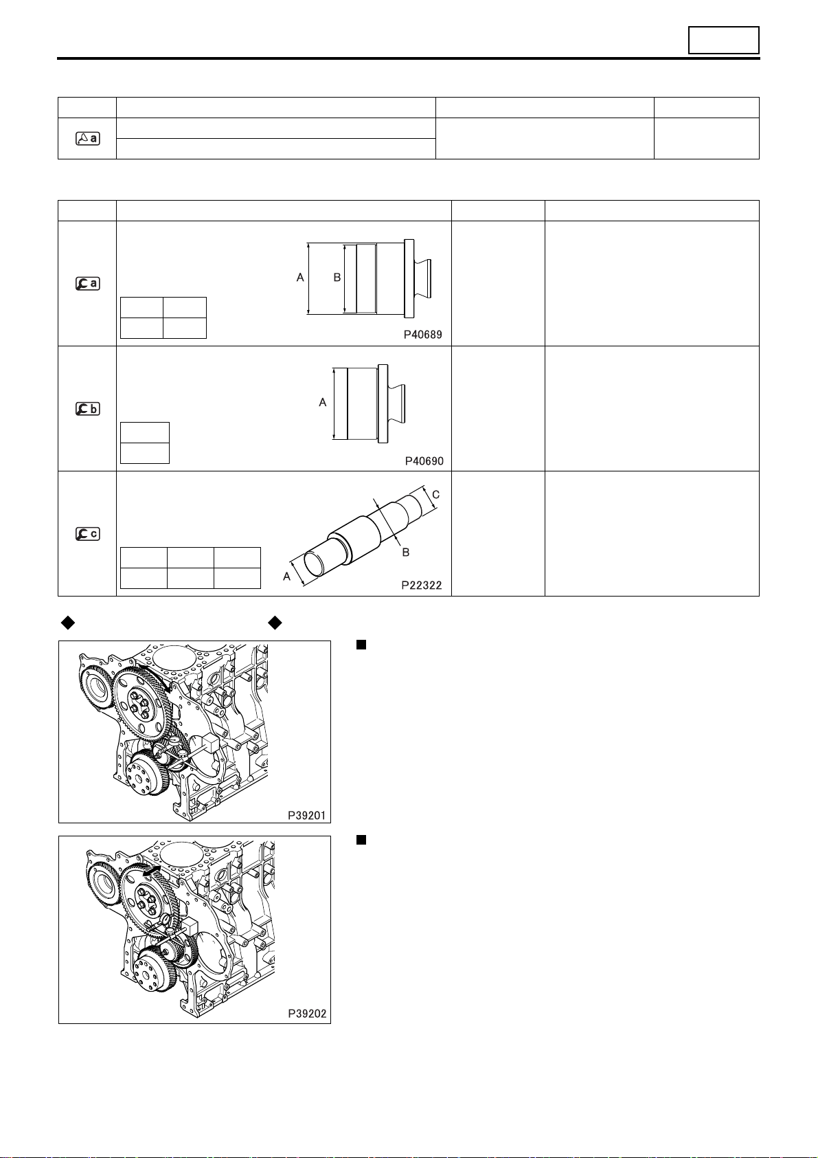
11
11-79
Lubricant and/or sealant
Special tools (Unit: mm)
Inspection before removal
Inspection: Backlash between gears
• For each pair of gears, measure the backlash at more than three
teeth.
• If any of the measurements exceeds the limit, replace the defec-
tive part(s).
Inspection: Idler gear end play
• If the measurement exceeds the limit, replace the defective
part(s).
Mark Points of application Specified lubricant and/or sealant Quantity
O-ring
Engine oil As required
Inside surface of bushing of gears
Mark Tool name and shape Part No. Application
ME350197 Removal of idler gear bushing
ME350198 Installation of idler gear bushing
MH062046
Removal and installation of idler gear
bushing
Idler gear bushing
puller
AB
φ 105 φ 100
Idler gear bushing in-
staller
A
φ 99.3
Idler gear bushing
puller
ABC
φ 45.5 φ 50 φ 46
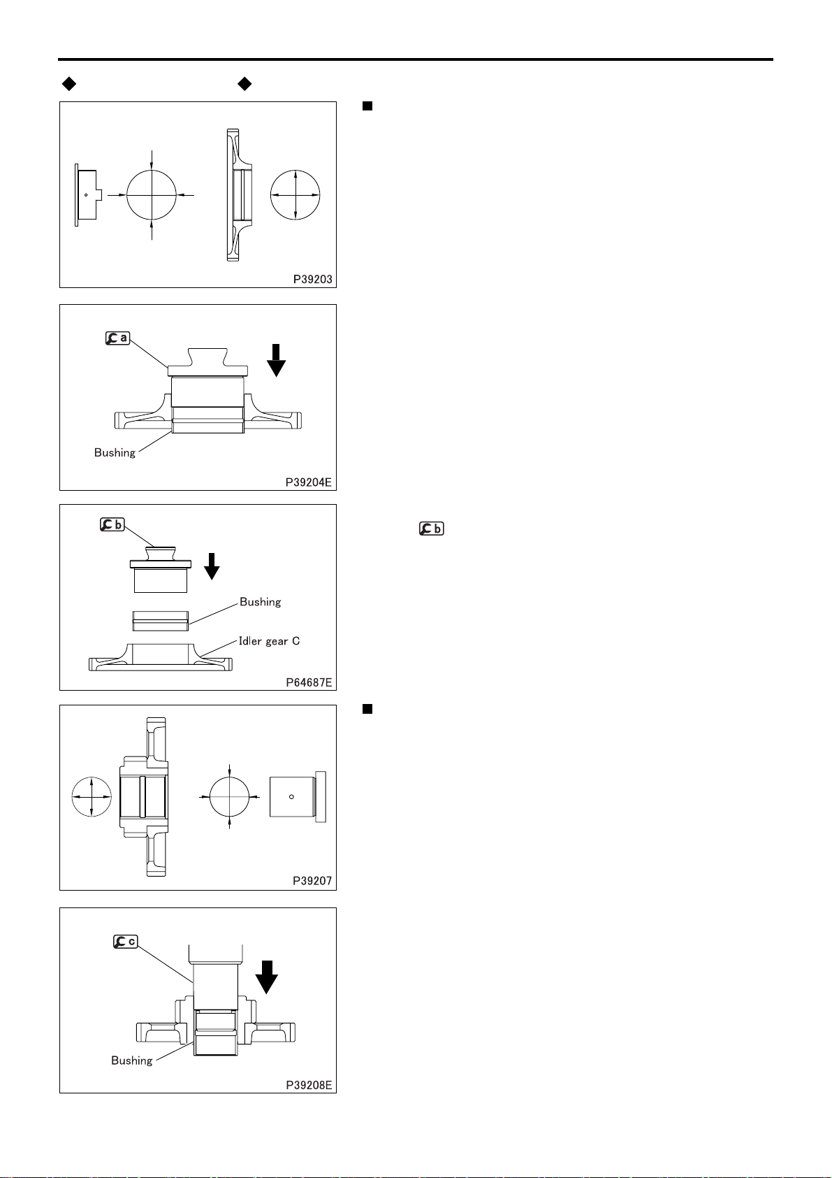
11-80
Inspection procedure
Inspection: Clearance between idler shaft C and idler gear
bushing
[Inspection]
• If the measurement exceeds the limit, replace the bushing.
Replacement of idler gear bushing
[Removal]
[Installation]
• Inst
all
until it contacts the idler gear with idler gear C facing
in the illustrated direction.
• After installation, measure the clearance again.
• If the measurement is less than the standard value, ream the
bushing.
Inspection: Clearance between idler shaft A, B and idler
gear bushing
[Inspection]
• If the measurement exceeds the limit, replace the bushing.
Replacement of idler gear bushing
[Removal]
TIMING GEARS <WITHOUT FLYWHEEL PTO>
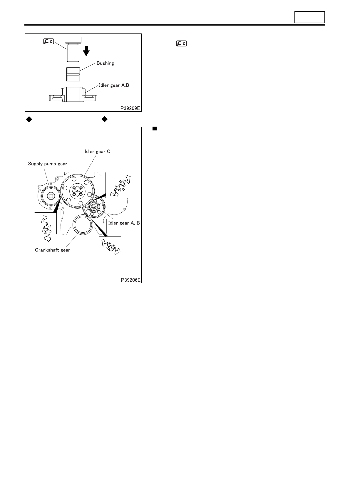
11
11-81
[Installation]
• Install until it contacts the idler gear with idler gear A, B fac-
ing in the illustrated direction.
• After installation, measure the clearance again.
• If the measurement is less than the standard value, ream the
bushing.
Installation procedure
Installation: idler gear
• Install idler gear A, B such that the alignment mark “A” on the
gear is aligned with the alignment mark “A” on the crankshaft
gear.
• When installing idler gear C, ensure that the alignment mark “B”
on the gear is aligned with the alignment mark “B” on idler gear
A, B and that the alignment mark “C” on idler gear C is aligned
with the alignment mark “C” on the supply pump gear.
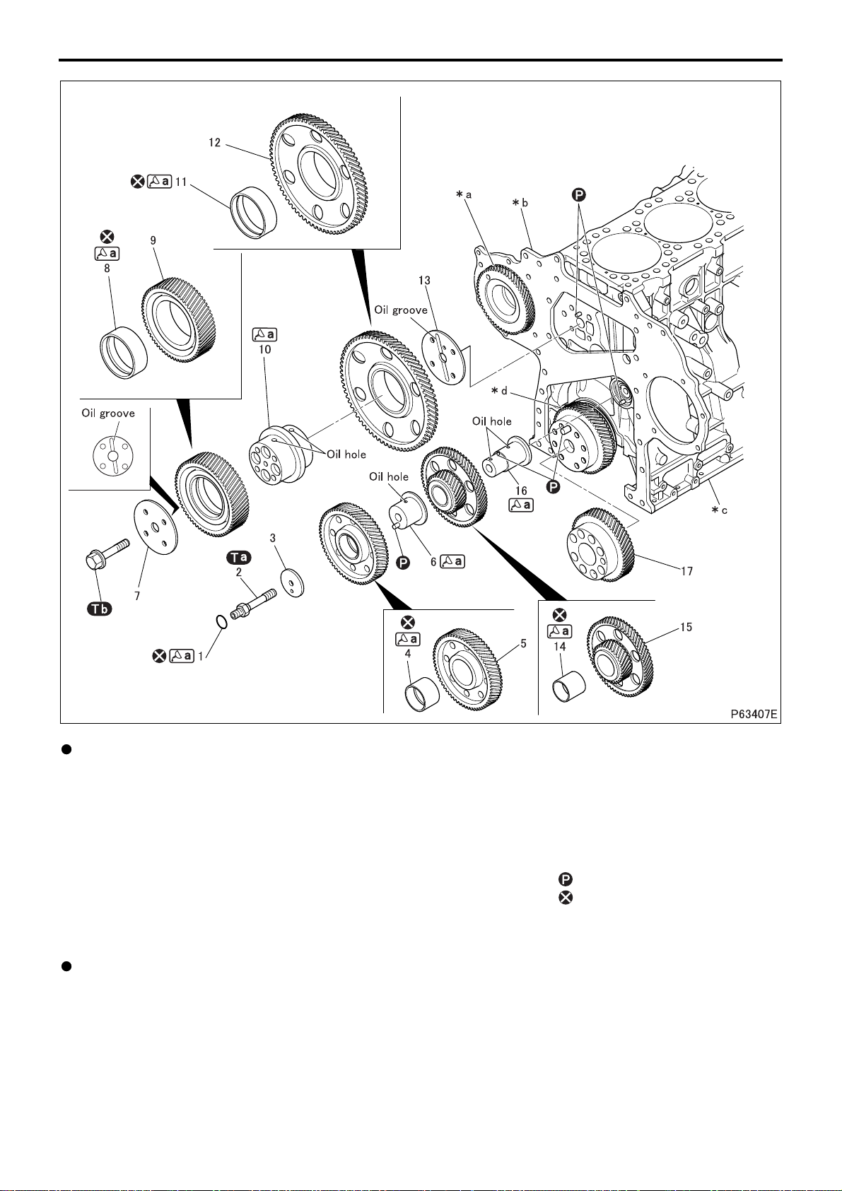
11-82
Disassembly sequence
Assembly sequence
Follow the disassembly sequence in reverse.
1 O-ring
2 Idler shaft bolt
3 Thrust plate A, B
4 PTO idler gear bushing
5 PTO idler gear A
6 Idler shaft B
7 Thrust plate C
8 PTO idler gear bushing
9 PTO idler gear B
10 Idler shaft C
11 Idler gear bushing
12 Idler gear C
13 Thrust plate C
14 Idler gear bushing
15 Idler gear A, B
16 Idler shaft A
17 PTO drive gear
*
a: Supply pump gear
*
b: Rear plate
*
c:Crankcase
*
d: Crankshaft gear
: Locating pin
: Non-reusable parts
M
ITSUBISHI 6M70 TIMING GEARS <WITH FLYWHEEL PTO>
Mitsubishi 6M70 Engine Parts contact:
email: [email protected]
Phone: 269 673 1638
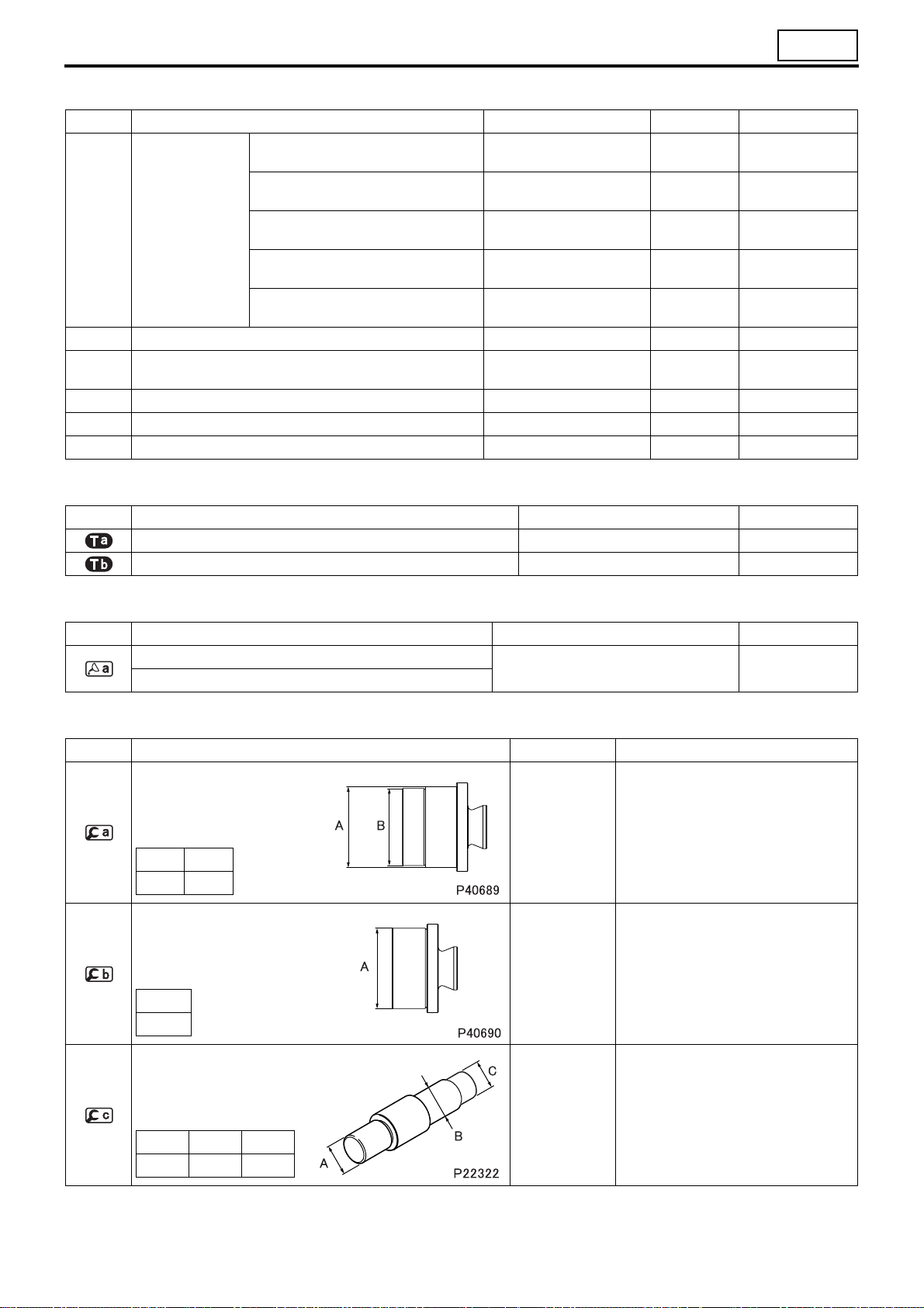
11
11-83
Service standards (Unit: mm)
Tightening torque (Unit: N·m {kgf·m})
Lubricant and/or sealant
Special tools (Unit: mm)
Location Maintenance item Standard value Limit Remedy
– Gear backlash
Between idler gear C and supply
pump gear
0.096 to 0.198 0.35 Replace
Between idler gear C and idler gear
A, B
0.089 to 0.181 0.35 Replace
Between idler gear A, B and crank-
shaft gear
0.076 to 0.196 0.35 Replace
Between PTO idler gear A and PTO
idler gear B
0.07 to 0.2 0.35 Replace
Between PTO idler gear A and drive
gear
0.07 to 0.2 0.35 Replace
4, 6 PTO idler gear bushing-to-idler shaft B clearance 0.03 to 0.068 0.2 Replace
5, 9, 12,
15
Idler gear end play 0.1 to 0.2 0.4 Replace
8, 10 PTO idler gear bushing-to-idler shaft C clearance 0.036 to 0.08 0.2 Replace
10, 11 Idler gear bushing-to-idler shaft C clearance 0.04 to 0.08 0.2 Replace
14, 16 Idler gear bushing-to-idler shaft A clearance 0.03 to 0.06 0.2 Replace
Mark Parts to be tightened Tightening torque Remarks
Idler shaft bolt (for installing PTO idler gear A, idler gear A, B) 155 {16} –
Bolt (for installing PTO idler gear B, idler gear C assembly) 80 {8.0} –
Mark Points of application Specified lubricant and/or sealant Quantity
O-ring
Engine oil As required
Gear bushing inner surface
Mark Tool name and shape Part No. Application
ME350197 Removal of idler gear bushing
ME350198 Installation of idler gear bushing
MH062046
Removal and installation of idler gear
bushing
Idler gear bushing
puller
AB
φ 105 φ 100
Idler gear bushing
installer
A
φ 99.3
Idler gear bushing
puller
ABC
φ 45.5 φ 50 φ 46
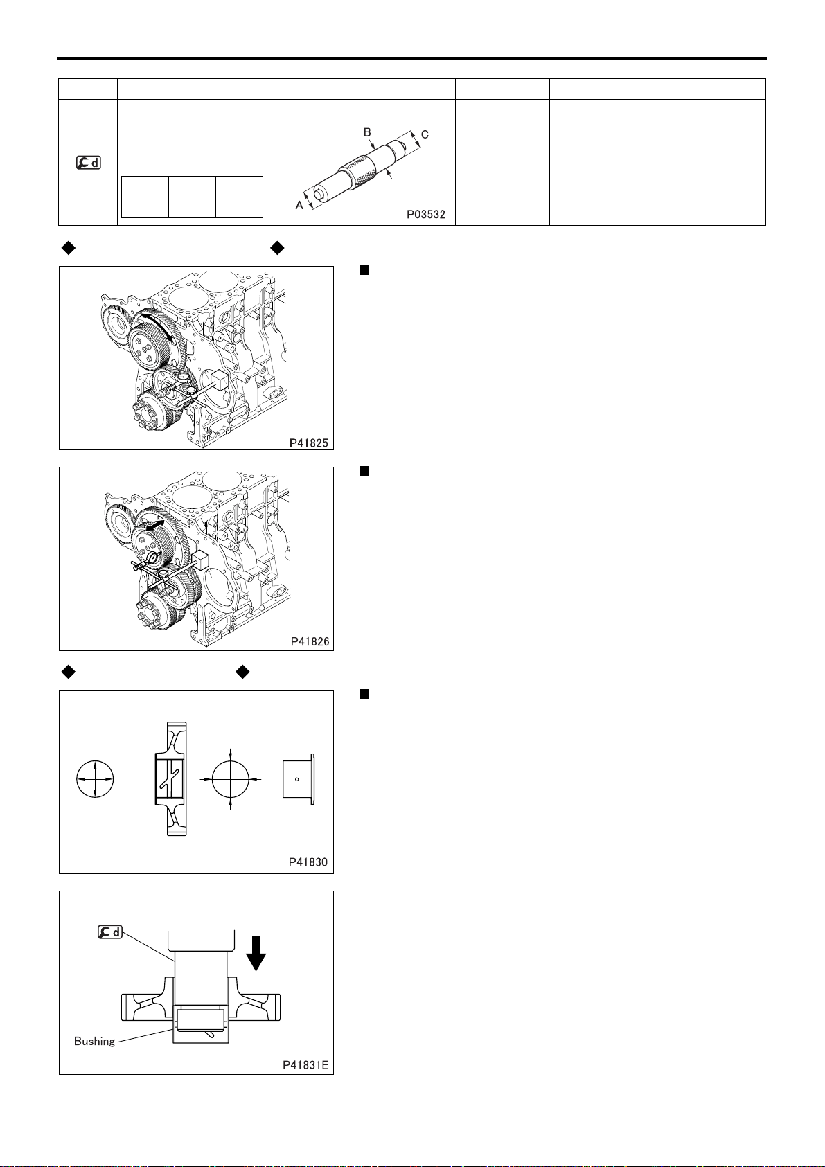
11-84
Inspection before removal
Inspection: Backlash between gears
• For each pair of gears, measure the backlash at more than three
teeth.
• If any of the measurements exceeds the limit, replace the defec-
tive part(s).
Inspection: Idler gear end play
• If the measurement exceeds the limit, replace the defective
part(s).
Inspection procedure
Inspection: Clearance between PTO idler gear bushing and
idler shaft B
[Inspection]
• If the measurement exceeds the limit, replace the bushing.
Replacement of PTO idler gear bushing
[Removal]
MH061256
Removal and installation idler gear
bushings
Mark Tool name and shape Part No. Application
Idler gear bushing
puller
ABC
φ 57.3 φ 62 φ 58
TIMING GEARS <WITH FLYWHEEL PTO>
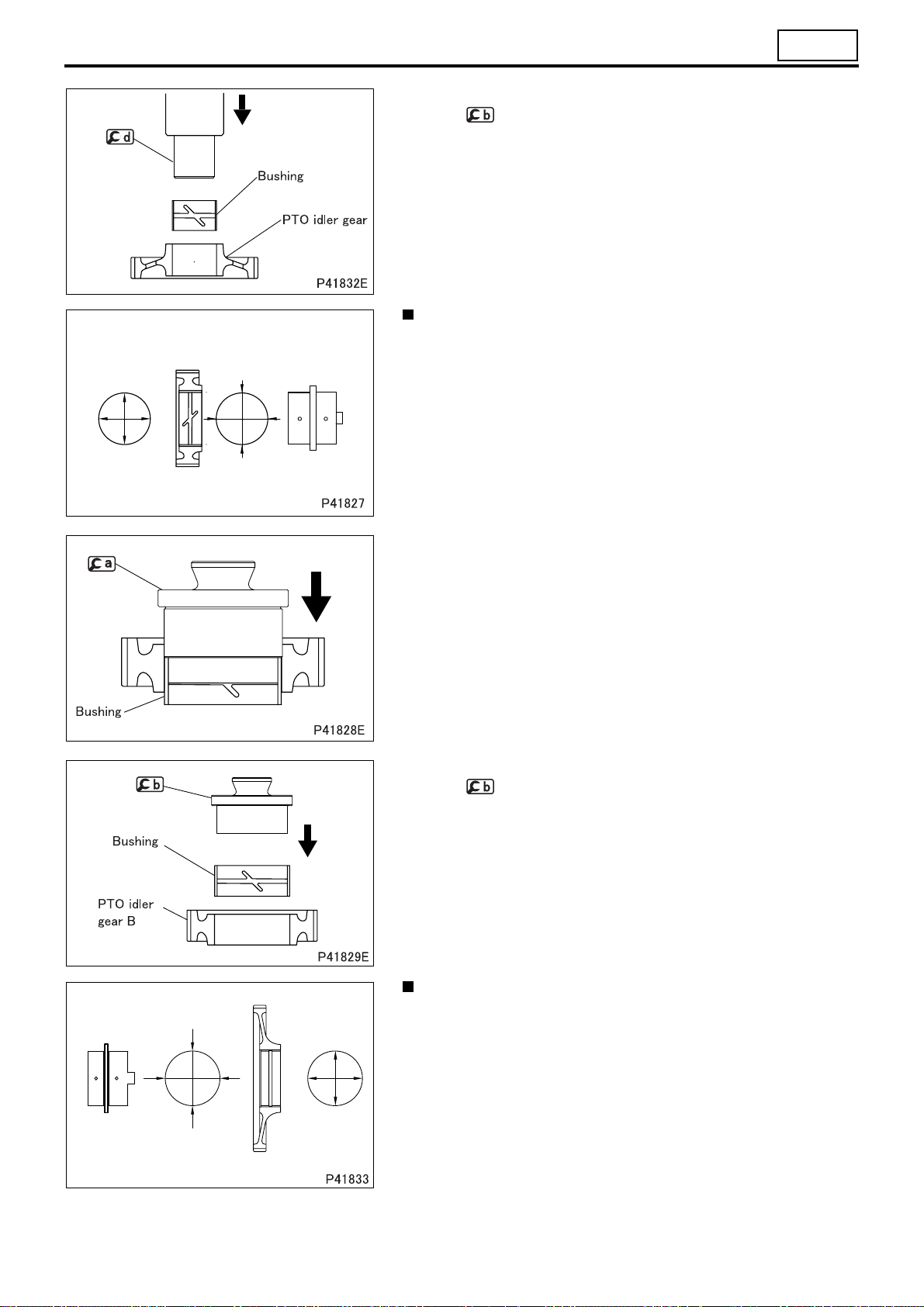
11
11-85
[Installation]
• Install until it contacts the PTO idler gear A with PTO idler
gear A facing in the illustrated direction.
• After installation, measure the clearance again.
• If the measurement is less than the standard value, ream the
bushing.
Inspection: Clearance between PTO idler gear bushing and
idler shaft C
[Inspection]
• If the clearance exceeds the limit, replace the bushing.
Replacement of PTO idler gear bushing
[Removal]
[Installation]
• Install until it contacts the PTO idler gear B with PTO idler
gear B facing in the illustrated direction.
• After installation, measure the clearance again.
• If the measurement is less than the standard value, ream the
bushing.
Inspection: Clearance between idler shaft C and idler gear
bushing
[Inspection]
• If the clearance exceeds the limit, replace the bushing.
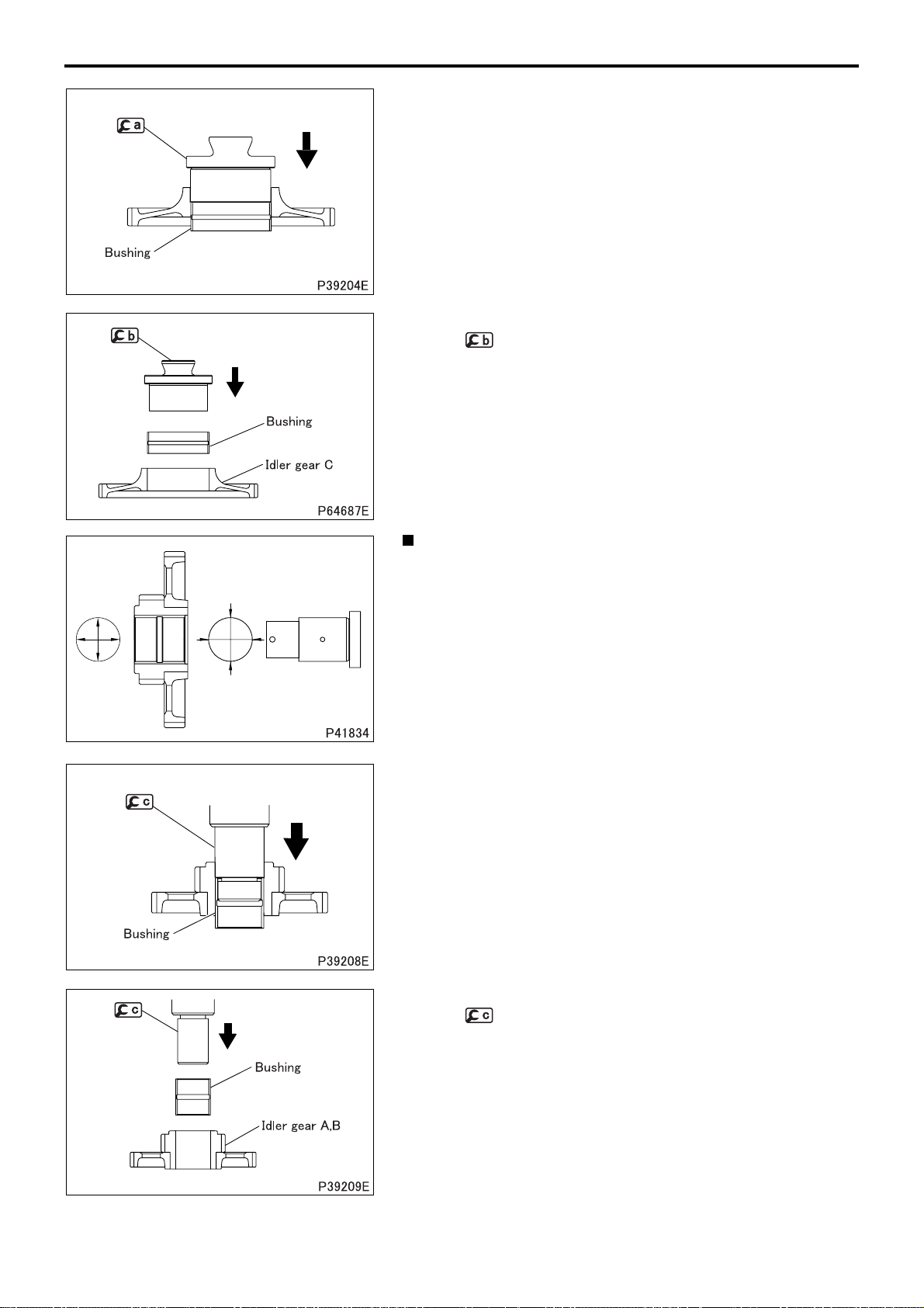
11-86
Replacement of idler gear bushing
[Removal]
[Installation]
• Install until it contacts the idler gear with idler gear C facing
in the illustrated direction.
• After installation, measure the clearance again.
• If the measurement is less than the standard value, ream the
bushing.
Inspection: Clearance between idler gear bushing and idler
shaft A
[Inspection]
• If the clearance exceeds the limit, replace the bushing.
Replacement of idler gear bushing
[Removal]
[Installation]
• Install until it contacts the idler gear with idler gear A, B fac-
ing in the illustrated direction.
• After installation, measure the clearance again.
• If the measurement is less than the standard value, ream the
bushing.
TIMING GEARS <WITH FLYWHEEL PTO>
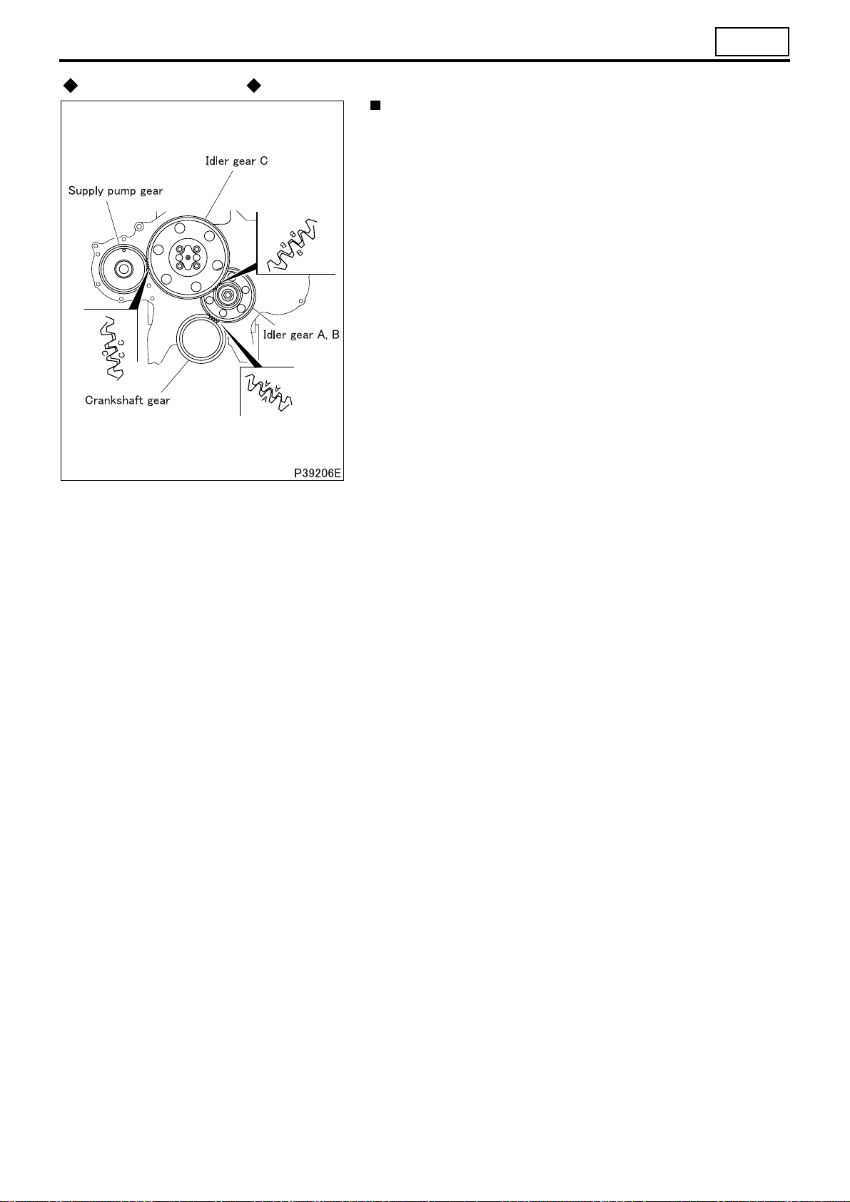
11
11-87
Installation procedure
Installation: Idler gear
• Install idler gear A, B such that the alignment mark “A” on the
gear is aligned with the alignment mark “A” on the crankshaft
gear.
• When installing idler gear C, ensure that the alignment mark “B”
on the gear is aligned with the alignment mark “B” on idler gear
A, B and that the alignment mark “C” on idler gear C is aligned
with the alignment mark “C” on the supply pump gear.
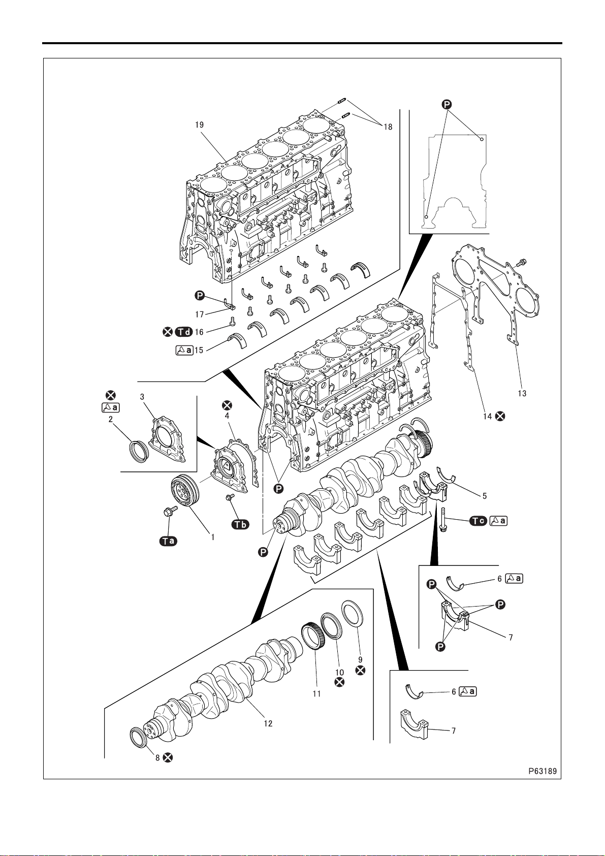
11-88
M
ITSUBISHI 6M70 CRANKSHAFT AND CRANKCASE
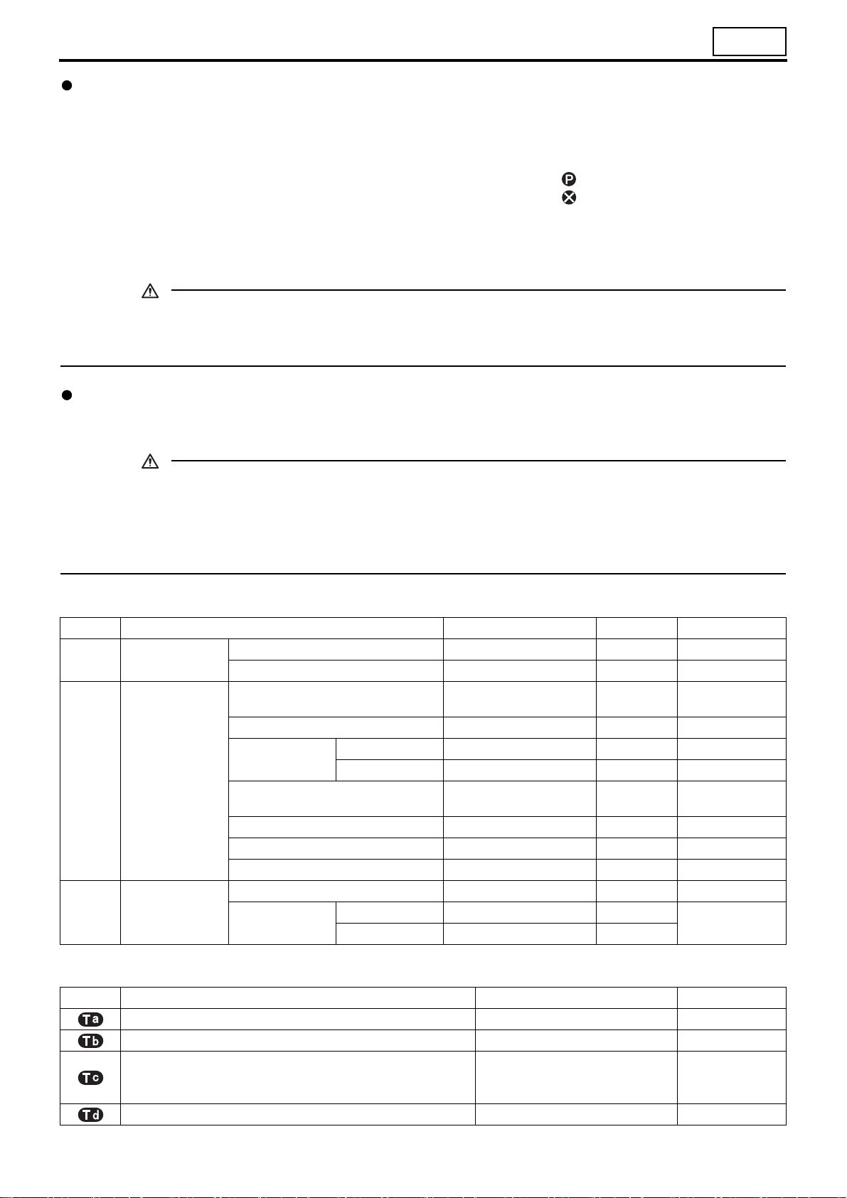
11
11-89
Disassembly sequence
CAUTION
• The check valve has been tightened using thread-locking compound and so, may deform during removal.
Once removed, the check valve must not be reused. Therefore, do not remove the check valve unless any
fault is found.
Assembly sequence
Follow the disassembly sequence in reverse.
CAUTION
• If overtightened, the check valve will not operate properly, leading to engine seizure. Be sure to tighten
the check valve to the specified torque.
• The main cap bolt is tightened within the plastic region. The number of punch marks indicates the num-
ber of times the bolt has been tightened. If there are 3 punch marks (tightened 3 times in the past), replace
the bolt.
M
itsubishi 6M70 Service standards (Unit: mm)
M
itsubishi 6M70 Tightening torque (Unit: N·m {kgf·m})
Location Maintenance item Standard value Limit Remedy
6, 15 Main bearing
Oil clearance 0.06 to 0.122 0.25 Replace
Span when free – 106.5 Replace
12 Crankshaft
End play 0.09 to 0.23 0.4
Replace thrust
plate
Bend 0.04 or less 0.1 Replace
Pins and journals
Roundness 0.01 or less 0.03 Rectify or replace
Cylindricity 0.006 or less – Rectify or replace
Center-to-center distance between
the journal and pin
75 ± 0.07 – Replace
Journal width 42 ± 0.3 – Replace
Pin width 54 – Replace
Fillet R5 – Replace
19 Crankcase
Distortion of top surface 0.07 or less 0.2 Rectify or replace
Cylinder block
Roundness 0.005 or less –
Replace
Cylindricity 0.015 or less –
Mark Parts to be tightened Tightening torque Remarks
Bolt (crankshaft pulley installation) 240 {24} –
Bolt (front cover installation) 45 {4.6} –
Bolt (main bearing cap installation) 100 {10} + 130 ± 2°
• Wet
• Can be reused
up to 3 times
Check valve 34 {3.5} –
1 Crankshaft pulley
2 Front oil seal
3 Front cover
4 Front cover gasket
5 Thrust plate
6 Lower main bearing
7 Main bearing cap
8 Front oil seal slinger
9 Ring
10 Rear oil seal slinger
11 Crankshaft gear
12 Crankshaft
13 Rear plate
14 Gasket
15 Upper main bearing
16 Check valve
17 Oil jet
18 Oil spray plug
19 Crankcase
: Locating pin
: Non-reusable parts
+0.2
0
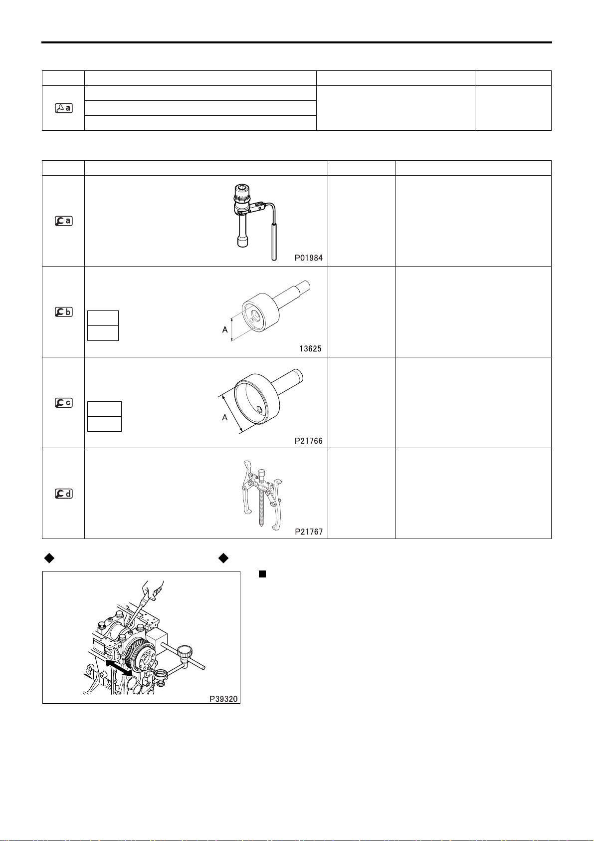
11-90
Lubricant and/or sealant
Special tools (Unit: mm)
Inspection before disassembly
Inspection: Crankshaft end play
• If the measurement exceeds the specified limit, replace the
oversized thrust plates.
Oversizes available: 0.15, 0.30, 0.45 mm
• Replace the crankshaft if the end play cannot be adjusted within
the standard range.
Mark Points of application Specified lubricant and/or sealant Quantity
Front oil seal lip
Engine oil As requiredThread of bolts
Inside surface of main bearing
Mark Tool name and shape Part No. Application
Socket wrench MH063365 Installation of main bearing cap
MH061817 Installation of front oil seal slinger
MH061652 Installation of ring
Gear puller MH061061 Removal of crankshaft gear
Front oil seal slinger
installer
A
φ 108
Rear oil seal slinger in-
staller
A
φ 123
CRANKSHAFT AND CRANKCASE
M
itsubishi 6M70 Engine Parts contact:
email: [email protected]
Phone: 269 673 1638
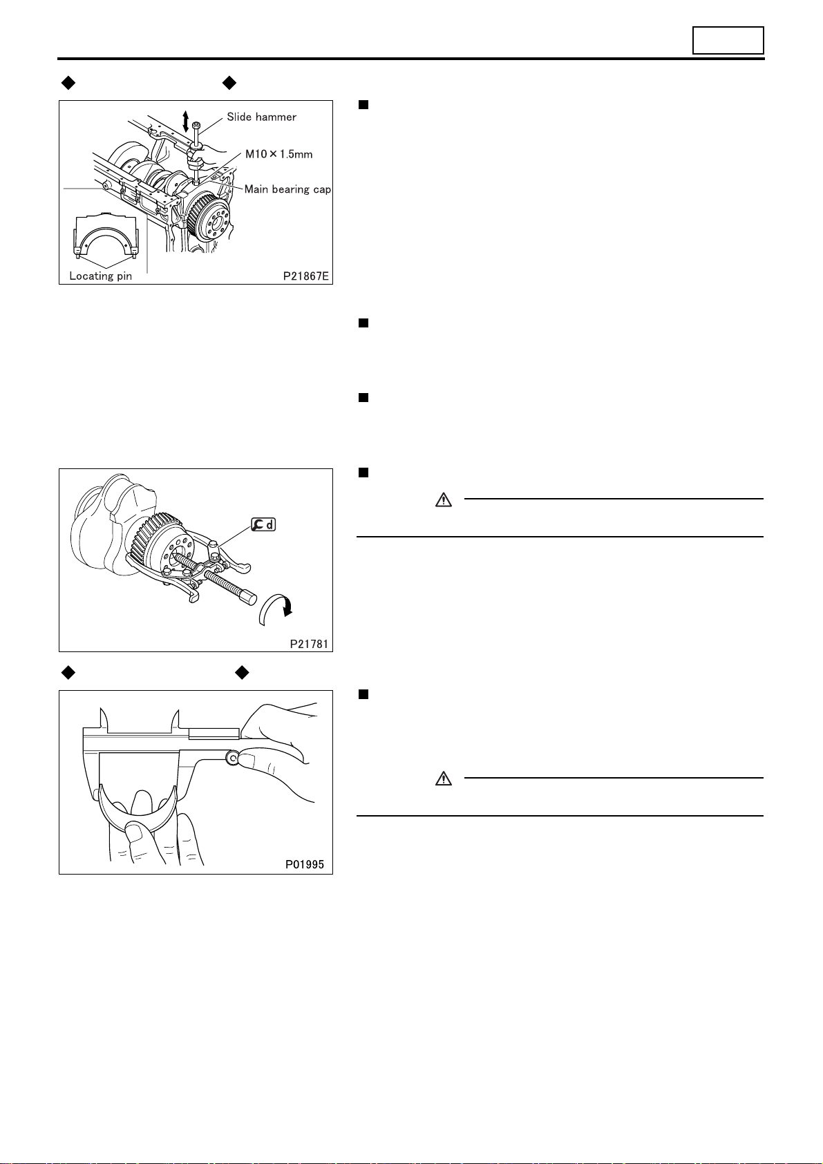
11
11-91
Removal procedure
Removal: Main bearing caps
• The main bearing cap on the rearmost part is located by locating
pins. Use a slide hammer to remove it.
Removal: Front oil seal slinger
• Taking care not to damage the crankshaft, split the slinger using
a chisel or a similar tool.
Removal: Ring
• Taking care not to damage the crankshaft, split the slinger using
a chisel or a similar tool.
Removal: Crankshaft gear
CAUTION
• Do not tap off the crankshaft gear as this can damage it.
Inspection procedure
Inspection: Main bearing
(1) Main bearing span when free
• If the measurement less than the limit, replace the upper and
lower bearings as a set.
CAUTION
• Do not attempt to manually expand the bearings.
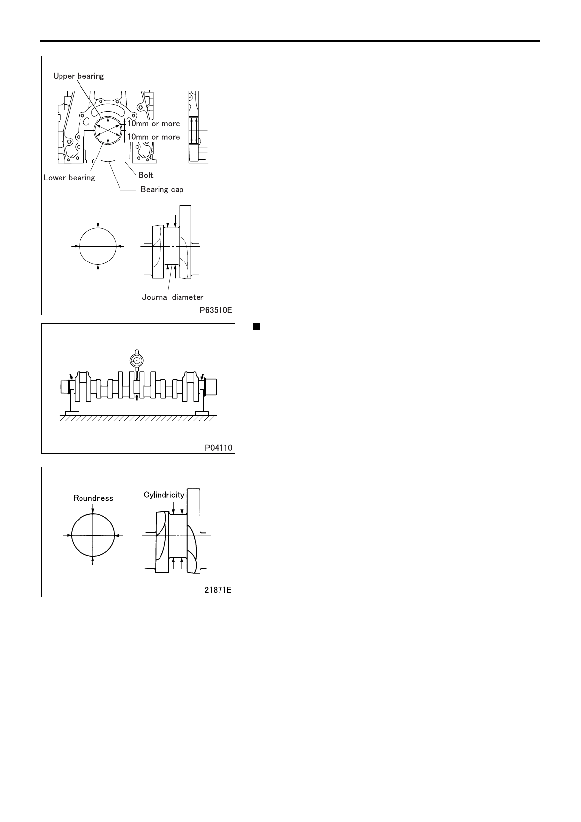
11-92
(2) Main bearing oil clearance
• Fit the upper main bearing into the crankcase and the lower
main bearing into the main bearing cap.
• Tighten the bolts to a torque of 100 N·m {10 kgf·m}.
• Measure the inner diameter of the main bearing and the outer di-
ameter of the corresponding crankshaft journal.
• If the difference between the measurements exceeds the speci-
fied limit, machine the crankshaft journal to one of the specified
undersize dimensions.
Inspection: Crankshaft
(1) Bend
• Measure the crankshaft at the center journal for bend while sup-
porting the shaft at the end journals.
• A half of the dial gauge reading obtained as the crankshaft is ro-
tated by a full turn represents the bend of the crankshaft.
• If the measurement exceeds the limit, replace the crankshaft.
(2) Roundness and cylindricity of crankshaft journals and
pins
• If any of the measurements exceeds the limits, grind the crank-
shaft journal(s) and/or pin(s) to undersize(s) or replace the
crankshaft.
CRANKSHAFT AND CRANKCASE
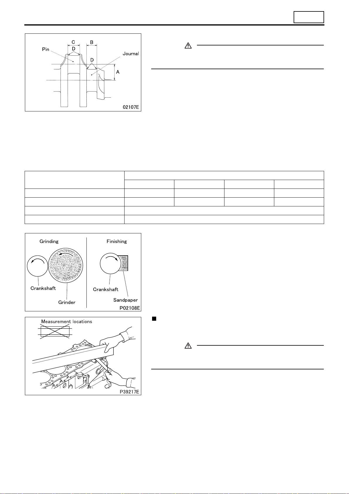
11
11-93
Grinding of crankshaft
CAUTION
• If the crankshaft pins and journals are ground to undersiz-
es, be sure to use bearings of corresponding undersizes.
• Check the measurement in the table of service standards and
correct the crankshaft as follows.
• Do not change the center-to-center distance A between the
journal and pin.
• Do not change the journal width B and the pin width C.
• Finish the fillets D smoothly.
• Carry out a magnetic inspection to check for cracks possibly
caused by grinding. Also, check that the hardness of the sur-
face has not dropped below Shore hardness number (Hs) 75.
• If there is any abnormality, replace the crankshaft.
Mitsubishi 6M70 Crankshaft undersize dimensions (Unit: mm)
• When grinding, turn both the crankshaft and the grinder counter-
clockwise as viewed from the crankshaft front end.
• When finishing the crankshaft with whestone or sandpaper, ro-
tate the crankshaft clockwise.
Inspection: Distortion of crankcase top surface
• If the measurement exceeds the limit, correct the crankcase top
surface with a surface grinder.
CAUTION
• Do not grind the crankcase top surface so much as to com-
promise the correct piston protrusion.
Undersizes
0.25 0.50 0.75 1.00
Finished journal outside diameter 99.75 99.50 99.25 99.00
Finished pin outer diameter 83.75 83.50 83.25 83.00
Roundness 0.01 or less
Cylindricity 0.006 or less
-0.08
-0.10
-0.08
-0.10
-0.08
-0.10
-0.08
-0.10
-0.06
-0.09
-0.06
-0.09
-0.06
-0.09
-0.06
-0.09
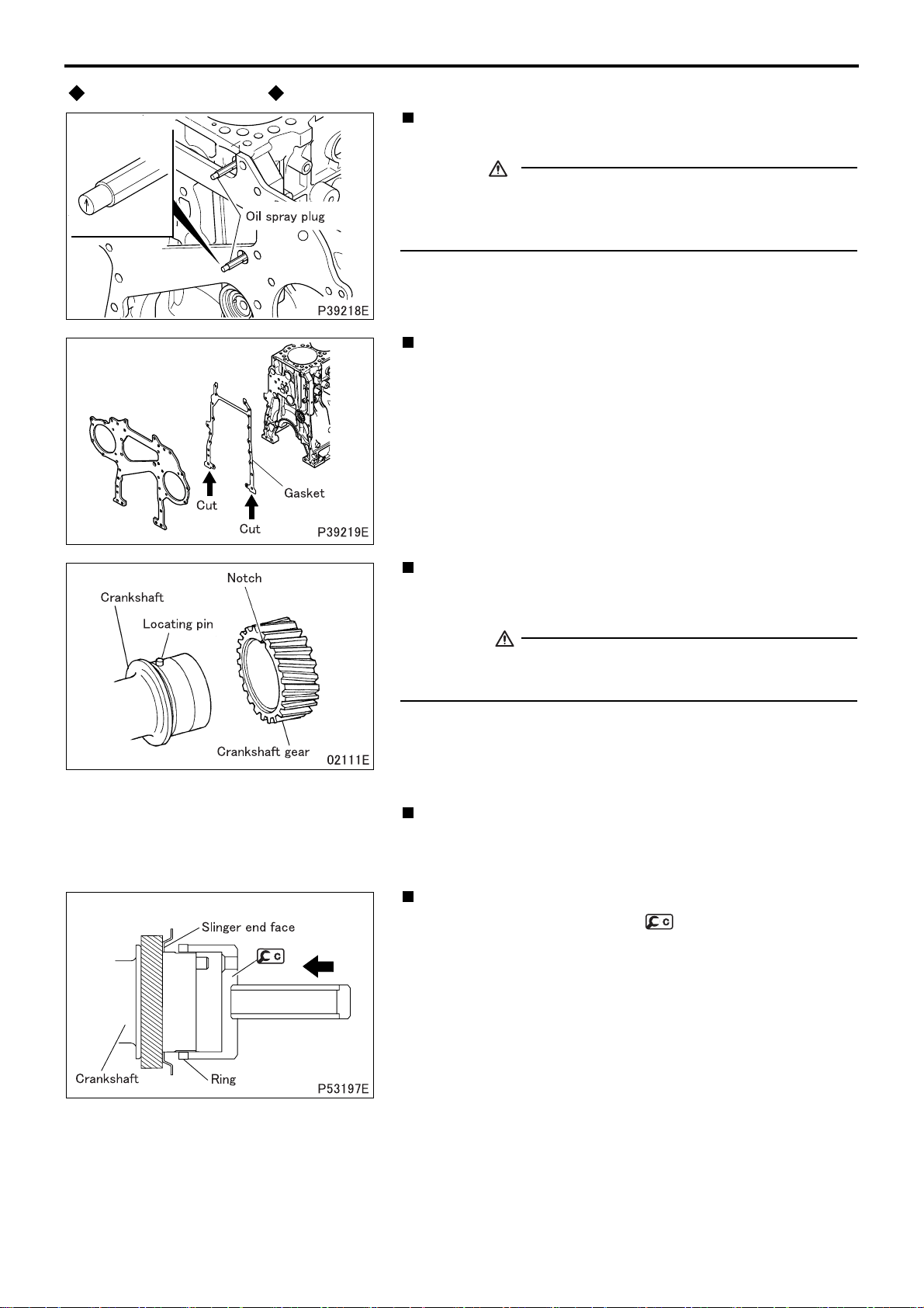
11-94
Installation procedure
Installation: Oil spray plug
• Install the oil spray plug in the illustrated direction.
CAUTION
• Be careful that if the direction of the oil spray plug is not ap-
propriate, oil supply to the timing gear becomes insuffi-
cient, causing seizure.
Installation: Gasket
• Lower parts of the gasket (oil pan mounting surface) protrude af-
ter installation. Cut the protruding parts after installing the fly-
wheel housing.
Installation: Crankshaft gear
• Heat the crankshaft gear to approximately 100°C with a burner
or the like.
WARNING
• You may burn yourself if you touch the heated crankshaft
gear.
• Align the locating pin fitted in the crankshaft with the notch in the
crankshaft gear. Drive the gear into position by lightly striking its
end face with a plastic hammer.
Installation: Rear oil seal slinger
• Install the rear oil seal slinger so that it is in close contact with
the crankshaft gear.
Installation: Ring
• To install the ring, push it in with until it comes into positive
contact with the slinger end face.
CRANKSHAFT AND CRANKCASE
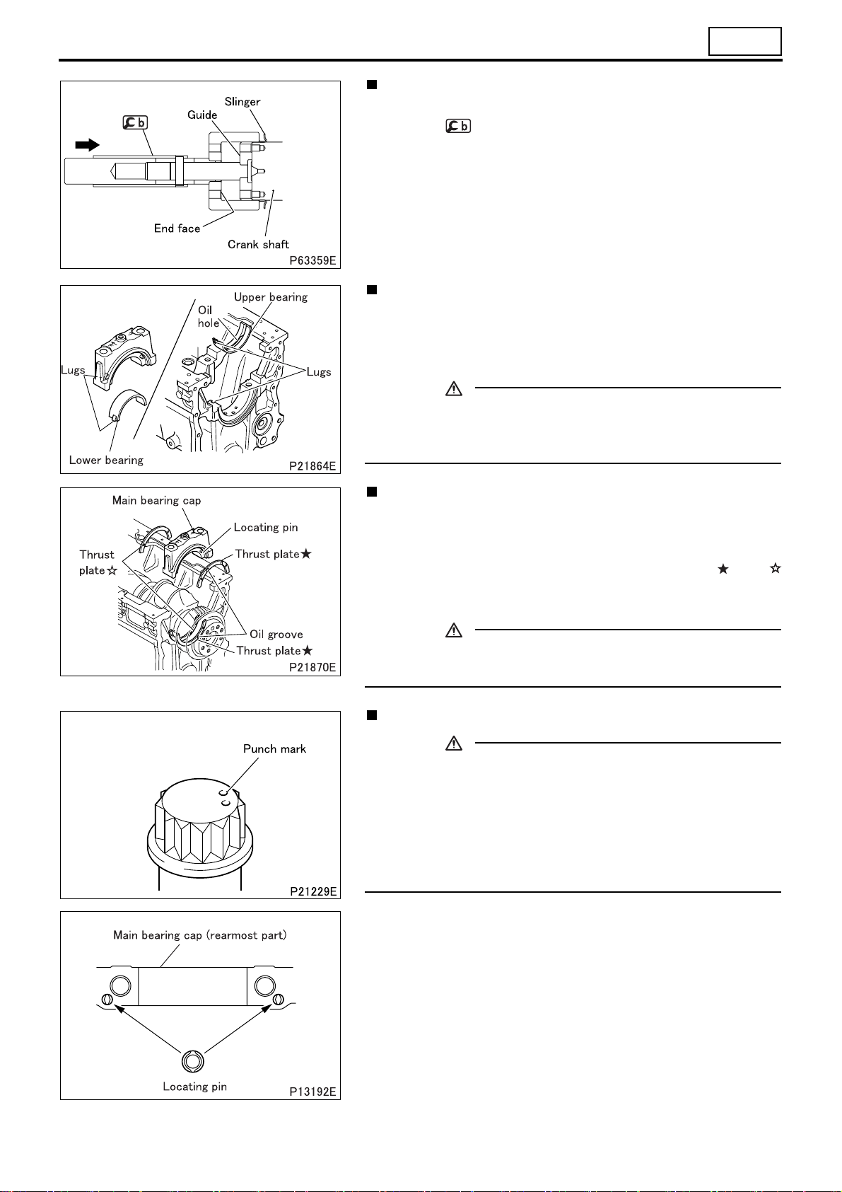
11
11-95
Installation: Front oil seal slinger
• Install the front oil seal slinger onto the crankshaft until the end
of face of securely contacts the guide.
Installation: Mitsubishi 6M70 Main bearing
• Install the main bearings with their lugs aligned as shown in the
illustration. When the crankshaft journals have been ground to
an undersize, use undersized main bearings.
Undersizes available: 0.25 mm, 0.50 mm, 0.75 mm, 1.00 mm
CAUTION
• The upper main bearing has an oil hole. The lower main
bearing has no oil hole. Do not confuse the upper and lower
bearings, as this can cause seizure in the engine.
Installation: Mitsubishi 6M70 Thrust plate
• Install thrust plates on both sides of the main bearing cap and
the rear end of the crankcase, ensuring that the oil grooves face
outside.
• If oversized thrust plates are to be used, those with an
d
marks must be the same in size. Oversizes available: 0.15 mm,
0.30 mm and 0.45 mm.
CAUTION
• If thrust plates are installed with the oil grooves facing in-
side, the engine may seize.
Installation: Main bearing cap
CAUTION
• Before installing bolts, check the number of punch marks
on the bolt head. (Bolt with up to two punch marks can be
reused.)
• The number of punch marks indicates the number of times
the bolt has been tightened in the past within the plastic re-
gion. If there are three punch marks (tightened three times
in the past), replace the bolt.
• Install locating pins in the illustrated direction for the main bear-
ing cap on the rearmost part.
Mitsubishi 6M70 Engine Parts contact:
email: [email protected]
Phone: 269 673 1638
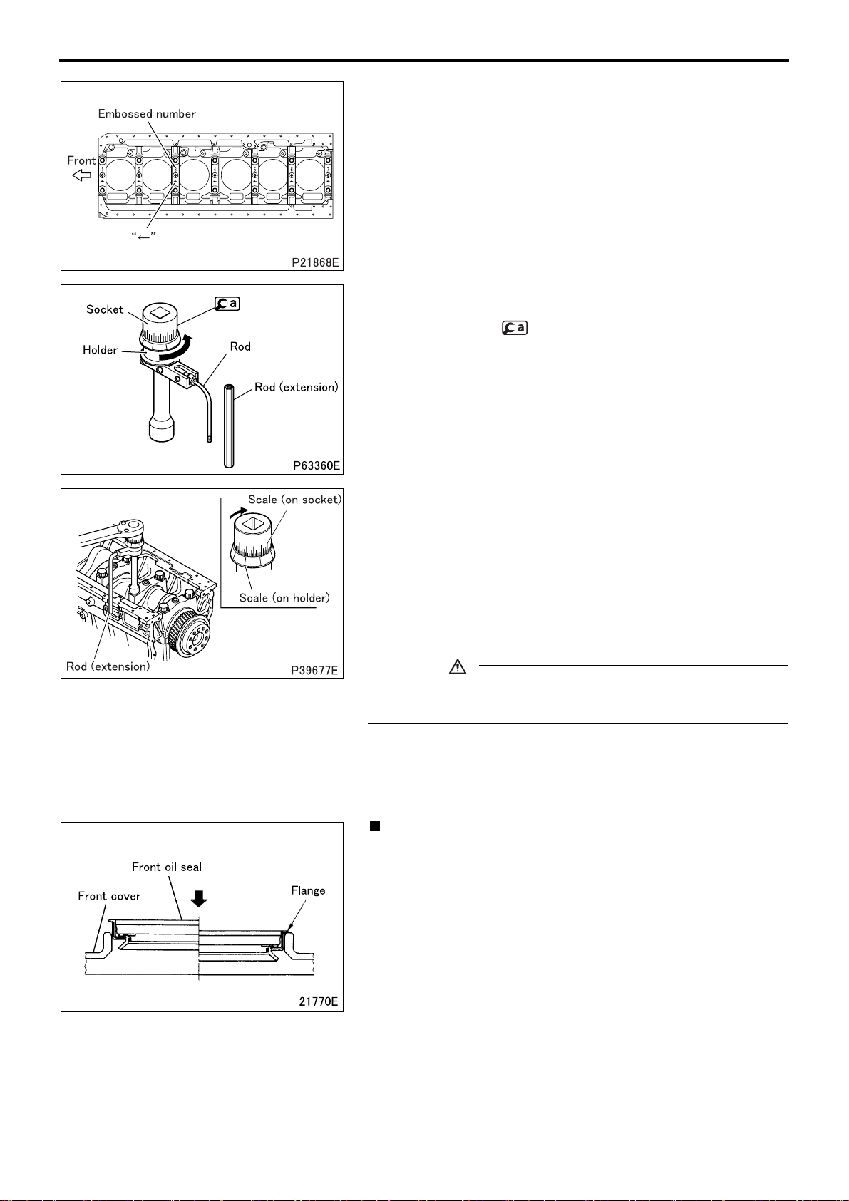
11-96
• Starting at the front of the engine, fit the main bearing caps in the
order of the embossed numbers with the embossed numbers
and front marks facing in the illustrated direction.
• Tighten all the bolts to 100 N·m {10 kgf·m}, then additionally
tighten them according in the following procedure.
• Turn the holder of counterclockwise to pretension the inter-
nal spring.
• Set the tool such that the rod (extension) is pressed against the
crankcase by the force of the spring.
• Align any line on the holder scale with any line on the socket
scale. (This will be used as the reference point = 0°.)
• From the reference point, turn the socket by 130° in the direction
shown. Each division on the socket scale represents 5°.
• After tightening the bolt within the plastic region, make a punch
mark on the bolt head to record the number of times that they
have been tightened
CAUTION
• The bolts should be tightened within the plastic region.
Never tighten them further than the specified angle.
• After tightening the bolt, rotate the crankshaft by hand. If it can-
not be rotated smoothly, inspect the main bearing cap for mount-
ing surface.
Installation: Mitsubishi 6M70 Front oil seal
• Install the front oil seal onto the front cover while pressing the
seal’s entire periphery ev
enly to prevent it from tilting.
• Install the front oil seal until its flange comes into positive contact
with the front cover.
CRANKSHAFT AND CRANKCASE

12-1
GROUP 12 LUBRICATION
SPECIFICATIONS.............................................................................. 12-2
STRUCTURE AND OPERATION
1. Lubrication System ........................................................................... 12-3
2. Oil Pump ............................................................................................. 12-4
3. Oil Cooler ........................................................................................... 12-5
4. Full-flow Oil Filter ........................................................................ 12-6
5. Bypass Oil Filter ........................................................................... 12-7
6. Engine Oil Pressure Switch .............................................................. 12-7
7. Regulator Valve .................................................................................. 12-7
8. Lubrication of Engine Components ................................................. 12-8
TROUBLESHOOTING ...................................................................... 12-11
ON-VEHICLE INSPECTION AND ADJUSTMENT
1. Oil Filter Replacement ..................................................................... 12-12
2. Engine Oil Replacement ................................................................. 12-14
3. Oil Pressure Measurement ............................................................. 12-15
OIL PAN, OIL JETS ......................................................................... 12-16
OIL PUMP, OIL STRAINER ............................................................. 12-18
OIL FILTER ...................................................................................... 12-22
OIL COOLER ................................................................................... 12-24
REGULATOR VALVE ....................................................................... 12-26

12-2
Item Specifications
Method of lubrication Oil pump type
Oil filter Filter paper element center bolt type
Oil cooler Shell and plate type (multiple-plate type)
Engine oil
Grade
API classification CD, CD/SF, CE, CE/SF, CF-4 or JASO
classification DH-1, DH-2
Quantity dm
3
{L}
Oil pan Approx. 31.5 {31.5}
Oil filter 4 to 4.5 {4 to 4.5}
SPECIFICATIONS
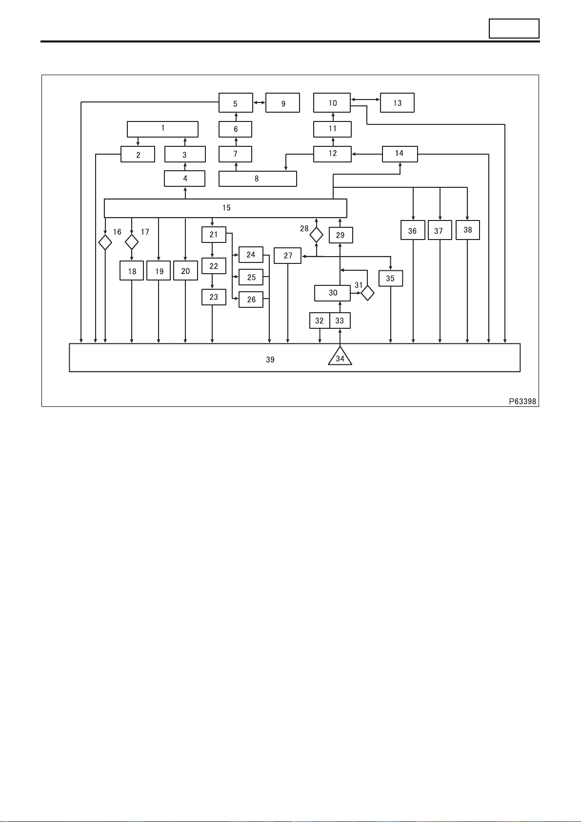
12
12-3
1. Lurication System
1 Rocker shaft
2 Camshaft journal (No.2 to 7)
3 Camshaft journal (No.1)
4 Rocker case (No.1)
5 Slave piston (No.1 to 5)
6 Camshaft cap (No.2 to 6)
7 Rocker case (No.2 to 6)
8 Cylinder head sub oil gallery
9 Master piston (No.1 to 5)
10 Slave piston (No.6)
11 Camshaft cap (No.7)
12 Rocker case (No.7)
13 Master piston (No.6)
14 Powertard solenoid valve
15 Main oil gallery
16 Regulator valve
17 Check valve for oil jet
18 Piston
19 Air compressor
20 Turbocharger
21 Main bearing
22 Connecting rod bearing
23 Connecting rod bushing
24 Idler gear A, B
25 Oil spray plug
26 Oil spray plug
27 Bypass oil filter
28 Oil cooler bypass valve
29 Oil cooler
30 Full-flow oil filter
31 Engine oil bypass
alarm switch
32 Relief valve
33 Oil pump
34 Oil strainer
35 Supply pump
36 Idler gear C
37 Idler gear D
38 Flywheel PTO
39 Oil pan
STRUCTURE AND OPERATION
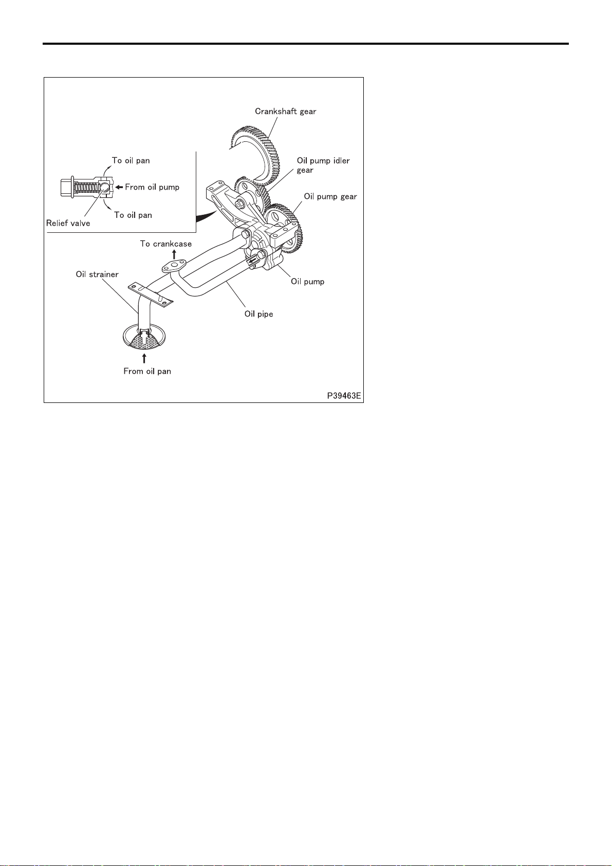
12-4
2. Mitsubishi 6M70 Oil Pump
• This engine uses a gear-type oil pump
driven by the rotation of the crankshaft
transmitted through the engagement
of the crankshaft gear and the oil
pump gear.
The oil pump has a relief valve, which
prevents excessive pressure from
building up inside the lubricating sys-
tem by allowing part of the engine oil
to escape to the oil pan when the oil
pressure exceeds a specified level.
STRUCTURE AND OPERATION
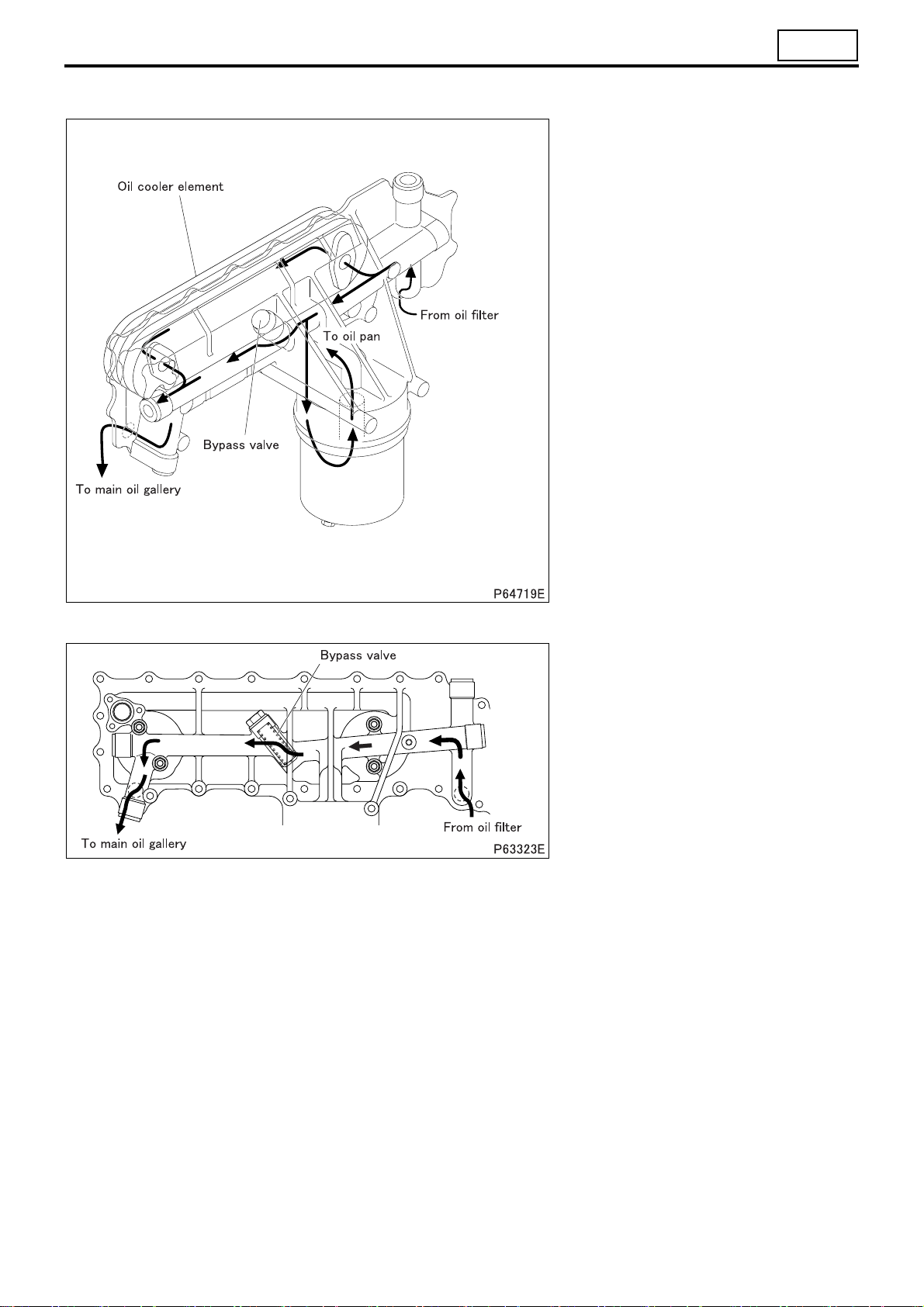
12
12-5
3. Mitsubishi 6M70 Oil Cooler
3.1 Mitsubishi 6M70 Bypass valve
• When the engine oil is cool and its vis-
cosity is high, or when the oil cooler el-
ement becomes clogged and restricts
the flow of the engine oil, the bypass
valve opens to let the engine oil by-
pass the oil cooler and flow directly to
the main oil gallery.
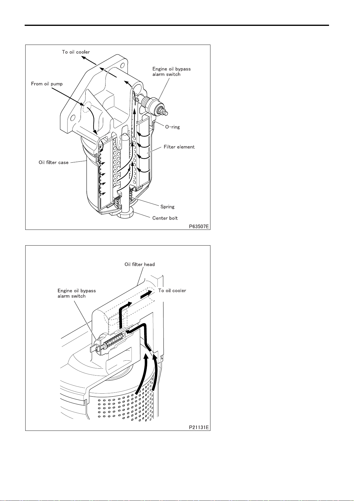
12-6
4. Full-flow Oil Filter
• The filter elements use elements
made of filter paper.
4.1 Engine oil bypass alarm switch
• If the full-flow oil filter elements clog
up, this will restrict the flow of engine
oil, causing various parts of the engine
to seize. To prevent this, the engine oil
bypass alarm switch is installed.
• If the full-flow oil filter clogs up, the en-
gine oil bypass alarm switch trips in
such a way as to direct the engine oil
straight on to the oil cooler, bypassing
the filter elements. When the engine
oil bypass alarm switch trips, the rele-
vant warning lamp illuminates to alert
the operator to the clogged full-flow oil
filter elements.
STRUCTURE AND OPERATION
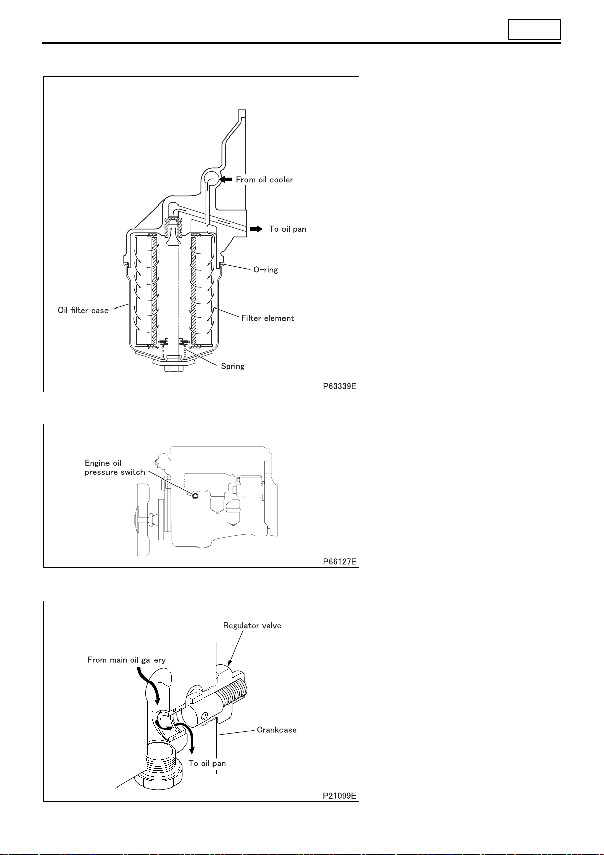
12
12-7
5. Bypass Oil Filter
• The oil filter elements use elements
made of filter paper.
6. Mitsubishi 6M70 Engine Oil Pressure Switch
• If the oil pressure of the engine oil fed
to the main oil gallery drops below the
specified value, the engine oil pres-
sure switch trips and illuminates the
relevant warning lamp to alert the op-
erator to the abnormal oil pressure.
7. Mitsubishi 6M70 Regulator Valve
• If the oil pressure in the main oil gal-
lery exceeds the specified value, the
regulator valve opens and returns a
portion of the engine oil to the oil pan
to adjust the oil pressure.
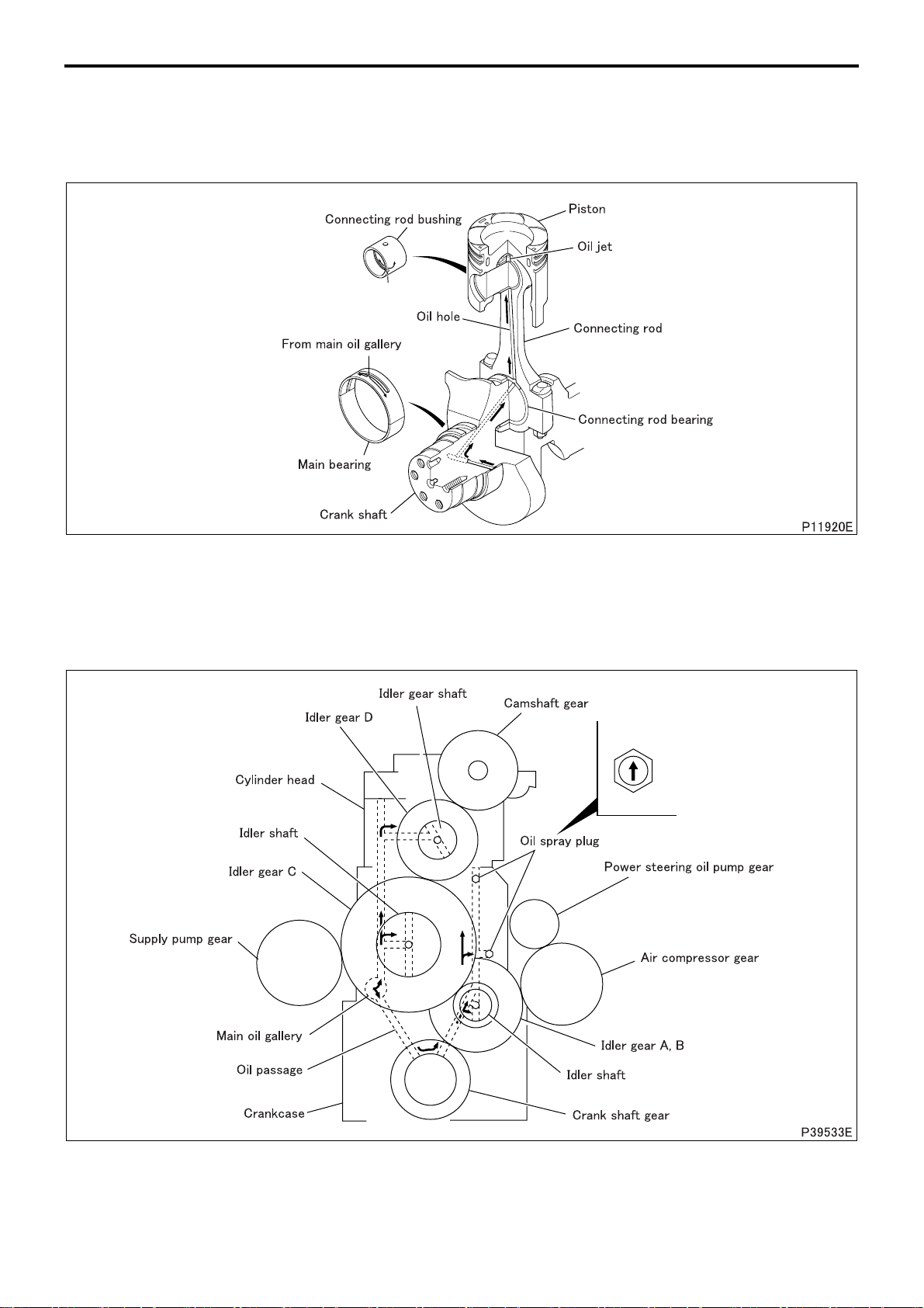
12-8
8. Lubrication of Engine Components
• The engine oil in the main oil gallery lubricates the engine components in the following ways.
8.1 Mitsubishi 6M70 Main bearing and connecting rod bearing
• Engine oil supplied through an oil passage in the crankshaft lubricates the big end (connecting rod bearing) of
each connecting rod. Simultaneously, engine oil supplied through an oil passage in the connecting rod lubricates
the connecting rod’s small end (connecting rod bushing). Beside, engine oil is sprayed out of the oil jet in the head
of the connecting rod into the piston to cool the piston.
8.2 Mitsubishi 6M70 Timing gears
• Engine oil in the main oil gallery is directed through the oil passages in the crankcase and cylinder head and is
used to lubricate the various gear shafts. After lubricating the gear shafts, the oil is used to lubricate the gears be-
fore returning the oil pan. Engine oil also lubricates the gears by the oil spray plugs. The oil spray plug has an ar-
row showing the installed direction on its head.
STRUCTURE AND OPERATION
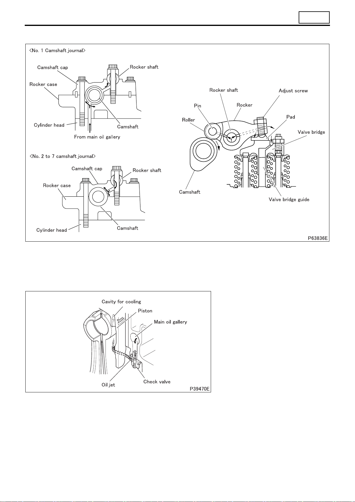
12
12-9
8.3 Mitsubishi 6M70 Valve mechanism
• Engine oil in the main oil gallery is directed through the oil passages in the cylinder head, rocker case and cam-
shaft cap, and lubricates the No. 1 journal of the camshaft before being fed to the rocker shaft. The oil flowing
through the oil passages in the rocker shaft lubricates No. 2 to No. 7 journals of the camshaft and also lubricates
the rockers. The oil flowing to the adjusting screws on the rockers lubricates the valve bridges. After lubricating
the various parts, the oil returns to the oil pan.
8.4 Mitsubishi 6M70 Check valves and
oil jets
• An oil jet is fitted in the lower part of
the main oil gallery for each cylinder.
• Engine oil is sprayed out of the oil jet
into the piston to cool the piston.
• Each oil jet is fitted with a check valve
that opens and closes at predeter-
mined oil pressure levels. At low en-
gine speeds, the check valve closes to
maintain the required volume of oil in
the lubrication system and prevent re-
ductions in oil pressure.
Mits
ubishi 6M70 Engine Parts contact:
email: [email protected]
Phone: 269 673 1638
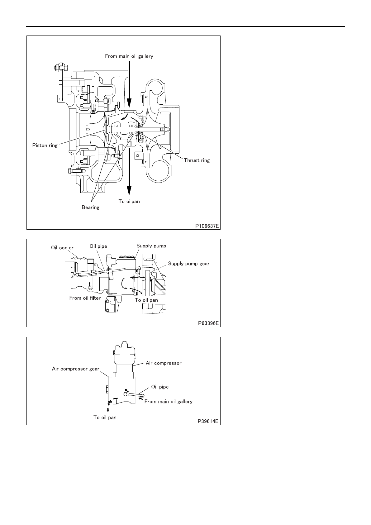
12-10
8.5 Mitsubishi 6M70 Turbocharger
• Engine oil in the main oil gallery is di-
rected through a pipe to the bearing
housing to lubricate the inner compo-
nents.
• A piston ring is provided on each end
of the turbine wheel shaft. The rings
function as oil sealing.
8.6 Mitsubishi 6M70 Supply pump
• The engine oil supplied to the supply
pump lubricates the inside of the pump
and supply pump gear.
• After lubricating the inside of the
pump, the oil is directed through the
timing gear train from the rear of the
pump and returns to the oil pan.
8.7 Mitsubishi 6M70 Air compressor
• The engine oil in the main oil gallery
lubricates the inside of the air com-
pressor, is directed through the timing
gear train from the air compressor
gear side, and returns to the oil pan.
STRUCTURE AND OPERATION
12
12-11
Symptoms
Engine is difficult to start
Overheating
Low oil pressure
Excessive oil consumption (oil leakage)
Reference Gr
Possible causes
Oil cooler
Incorrectly mounted element O O O
Defective gasket O O O
Defective O-ring O O O
Clogged element O O
Damaged element O O O
Weakened bypass valve spring O
Oil pump
Malfunctioning oil pump O O
Interference between oil pump gear and oil pump case
and/or cover
OO
Incorrectly connected oil pipe O O
Clogged oil strainer O O
Weakened relief valve spring O
Oil filter
Incorrect installation O
Clogged element O O
Defective O-ring O
Front cover
Defective front oil seal O
Gr11
Incorrectly mounted front cover O
Flywheel housing
Defective rear oil seal O
Incorrectly mounted flywheel housing O
Weakened regulator valve spring O
Defective piston cooling oil jet(s) O O
Oil working its way up into combustion chamber(s) through piston rings O
Gr11
Oil working its way down into combustion chamber(s) through valves O
Too high oil viscosity O
Poor oil quality O
Deterioration of oil O
Excess of oil O
Fuel mixed with oil O
TROUBLESHOOTING
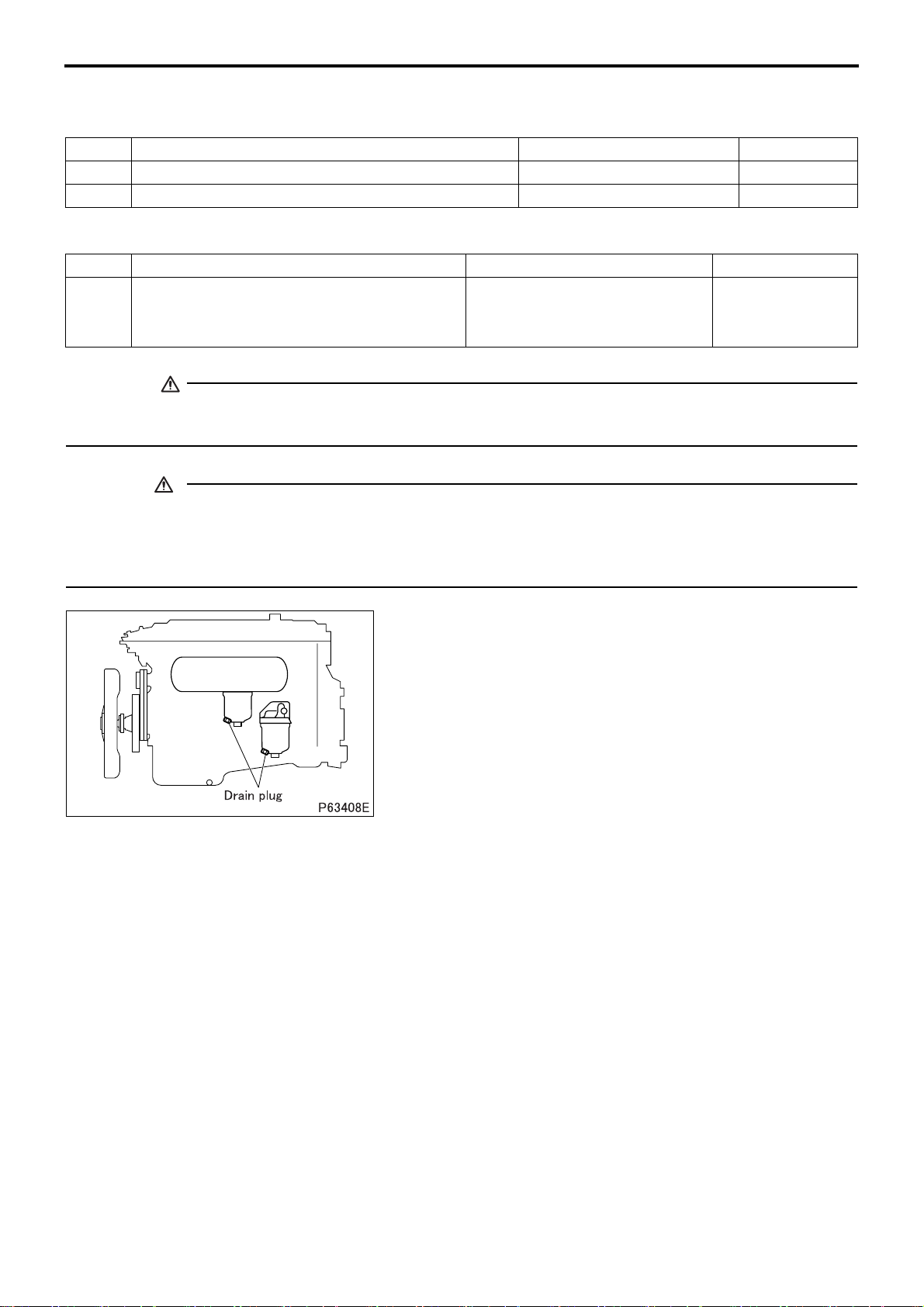
12-12
1. Oil Filter Replacement
Tightening torque (Unit: N·m {kgf·m})
Lubricant and/or sealant
WARNING
• Wipe up any spilled engine oil, as it can cause fires.
• To avoid any risk of burns, take care not to touch the engine oil when the engine is hot.
CAUTION
• Make sure not to put any engine oil on the belt when working on the oil filter. Belts soiled with oil or
grease may easily slip, resulting in deteriorated performance of the cooling system.
• Do not reuse the oil filter elements by washing.
• Install the gasket, taking care not to twist it.
[Removal]
• Remove the drain plug and drain the oil out of the oil filter.
Mark Parts to be tightened Tightening torque Remarks
– Drain plug (oil filter) 24.5 ± 4.9 {2.5 ± 0.5} –
– Center bolt 63.7 ± 4.9 {6.5 ± 0.5} –
Mark Points of application Specified lubricant and/or sealant Quantity
– Oil filter
Engine oil
API classification CD, CD/SF, CE,
CE/SF, CF-4 or JASO classification
DH-1, DH-2
4 to 4.5 dm
3
{4 to 4.5 L}
ON-VEHICLE INSPECTION AND ADJUSTMENT
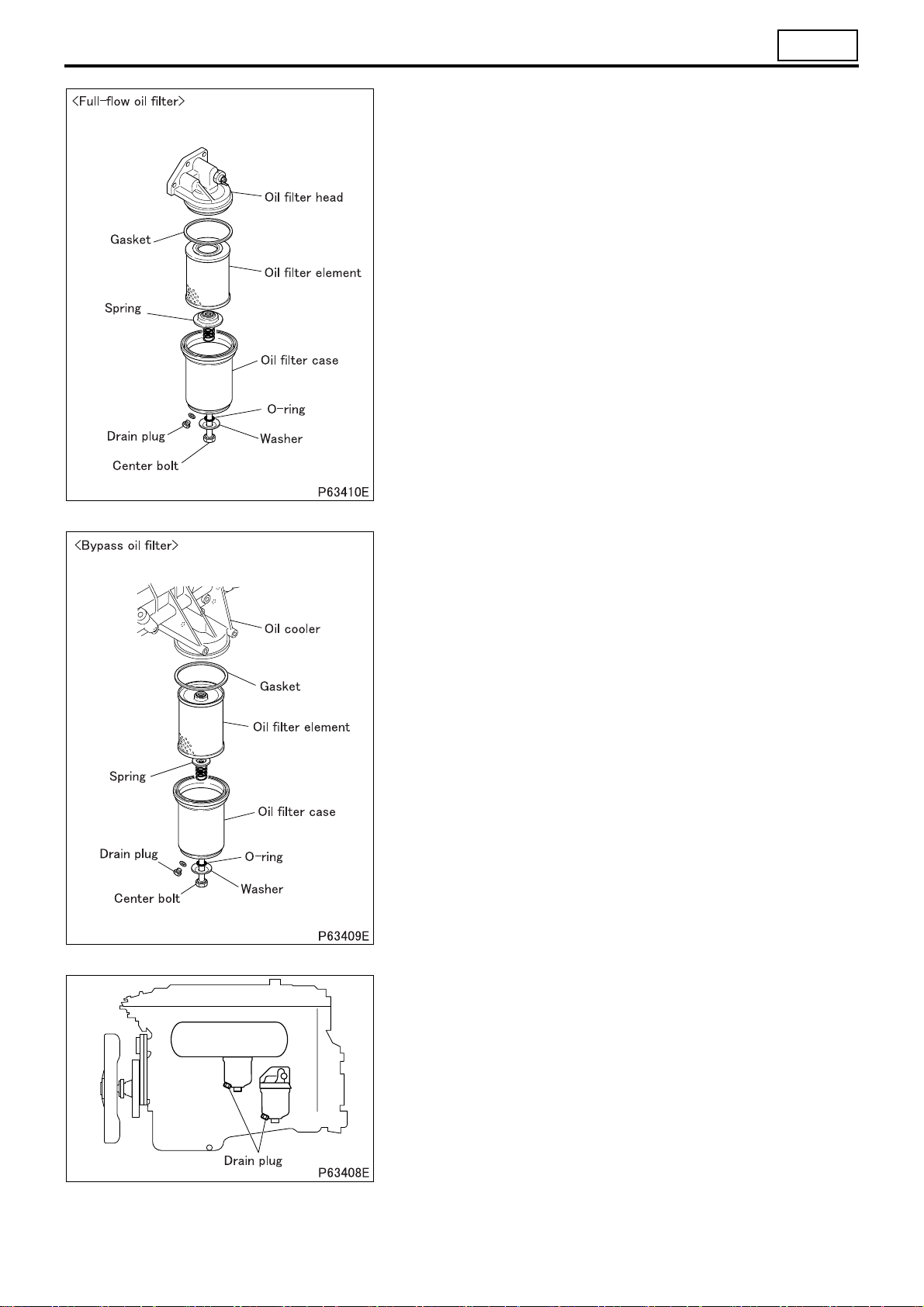
12
12-13
• Clean other parts than the element, O-ring and gasket to be re-
placed with washing oil.
[Installation]
• Replace the element, O-ring and gasket with new ones, respec-
tively.
• Install the oil filter case so that the drain plug is positioned as
shown in the illustration.
• With the oil filter installed, start the engine and ensure that there
is no oil leakage through the gasket.
• If oil is leaking, remove and reinstall the oil filter.
• Stop the engine and check the engine oil level.
• Add engine oil if the engine oil level is low.
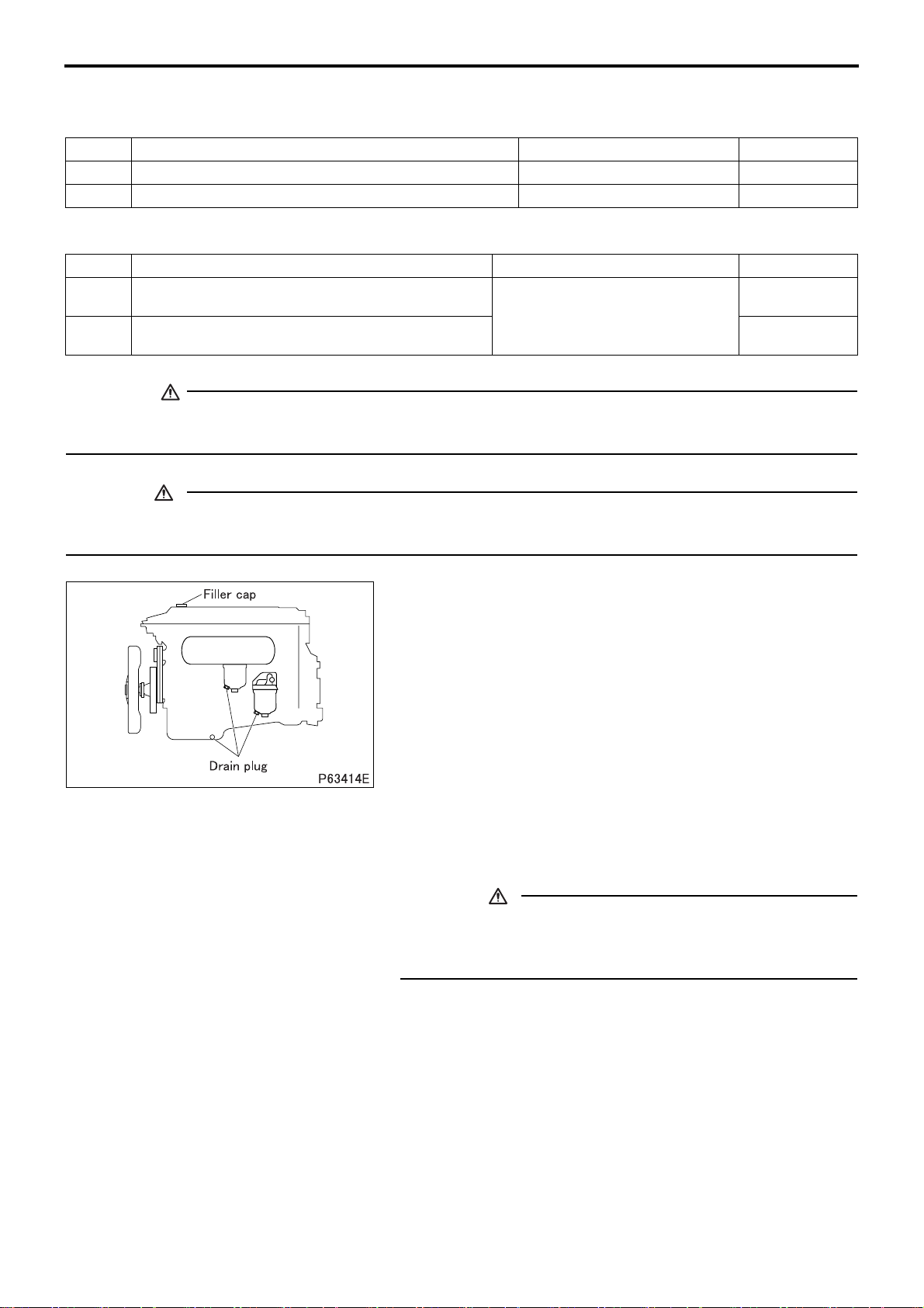
12-14
2. Engine Oil Replacement
Tightening torque (Unit: N·m {kgf·m})
Lubricant and/or sealant
WARNING
• Wipe up any spilled engine oil, as it can cause fires.
• To avoid any risk of burns, take care not to touch the engine oil when the engine is hot.
CAUTION
• Make sure not to put any engine oil on the belt when working on the oil filter. Belts soiled with oil or
grease may easily slip, resulting in deteriorated performance of the cooling system.
[Draining]
• Remove the filler cap.
• Remove the drain plugs of the oil filter or oil pan to drain out the
engine oil.
[Refilling]
• Tighten the drain plug to the specified torque, then pour a speci-
fied amount of new engine oil into the engine.
• Wait at least for 6 minutes after installing the filler cap and check
the engine oil level.
• Start the engine and ensure that there is no oil leakage.
• Stop the engine, wait at least for 30 minutes and check the en-
gine oil level.
• Add engine oil if the engine oil level is low.
CAUTION
• Do not add engine oil too much. An excessive oil level can
only lead to increased oil consumption or make the positive
crankcase ventilation system less efficient.
Mark Parts to be tightened Tightening torque Remarks
– Drain plug (oil filter) 24.5 ± 4.9 {2.5 ± 0.5} –
– Drain plug (oil pan) 68 {7} –
Mark Points of application Specified lubricant and/or sealant Quantity
– Oil filter
Engine oil
API classification CD, CD/SF, CE,
CE/SF, CF-4
or JASO classification DH-1, DH-2
4 to 4.5 dm
3
{4 to 4.5L}
– Oil pan
Approx. 31.5 dm
3
{31.5L}
ON-VEHICLE INSPECTION AND ADJUSTMENT
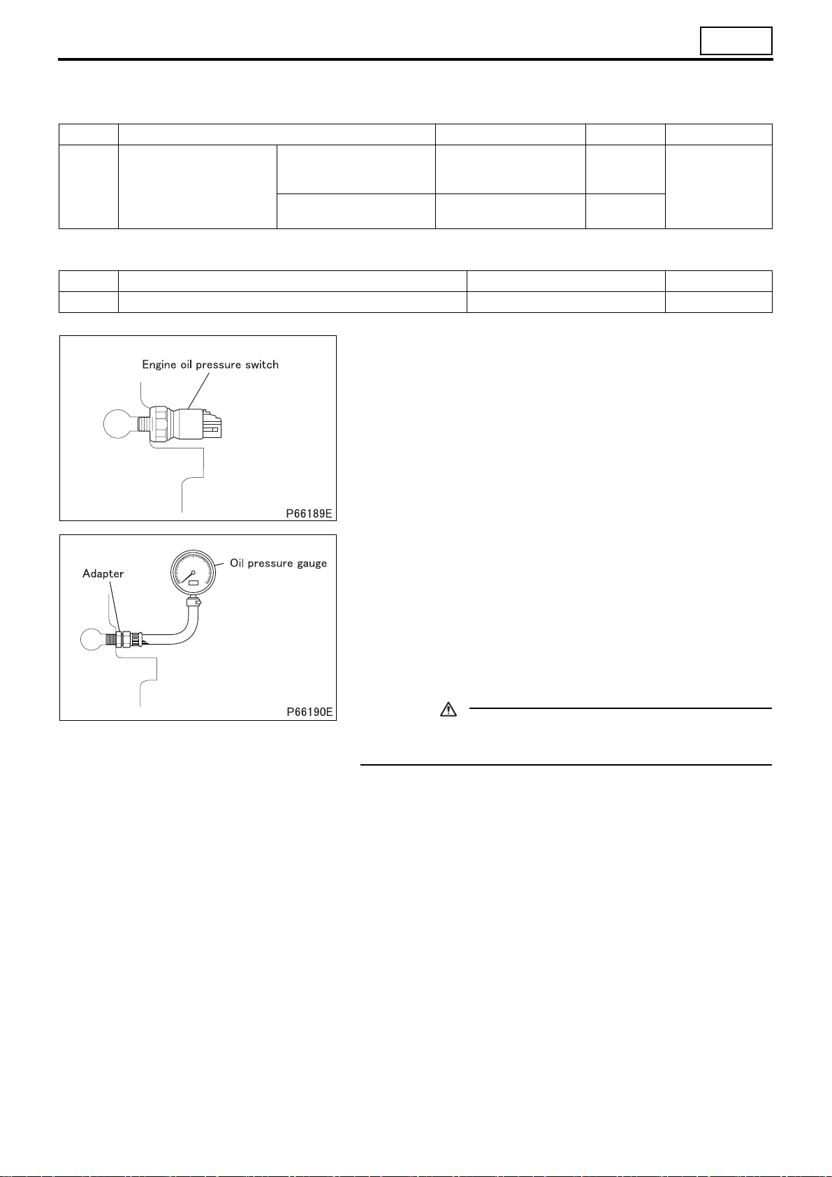
12
12-15
3. Oil Pressure Measurement
Service standards
Tightening torque (Unit: N·m {kgf·m})
• Remove the Mitsubishi 6M70 engine oil
pressure switch.
• Using an adapter, connect an oil pressure gauge to the engine
oil pressure switch mounting hole.
• Warm up the engine until the oil temperature reaches 70 to
90
°C.
• Measure the oil pressure while running the engine at a minimum
speed and then at maximum speed, both under no load.
• If the measurements are below the specified limits, overhaul the
lubrication system.
CAUTION
• Reinstall the oil pressure switch only when the engine is
cold.
Location Maintenance item Standard value Limit Remedy
–
Oil pressure (oil tempera-
ture at 70 to 90°C)
No-load minimum speed
135 to 295 kPa
{1.4 to 3 kgf/cm
2
}
49 kPa
{0.5 kgf/
cm
2
}
Inspect
No-load maximum speed
295 to 490 kPa
{3 to 5 kgf/cm
2
}
195 kPa
{2 kgf/cm
2
}
Mark Parts to be tightened Tightening torque Remarks
– Engine oil pressure switch 24.5 ± 4.9 {2.5 ± 0.5} With cold engine
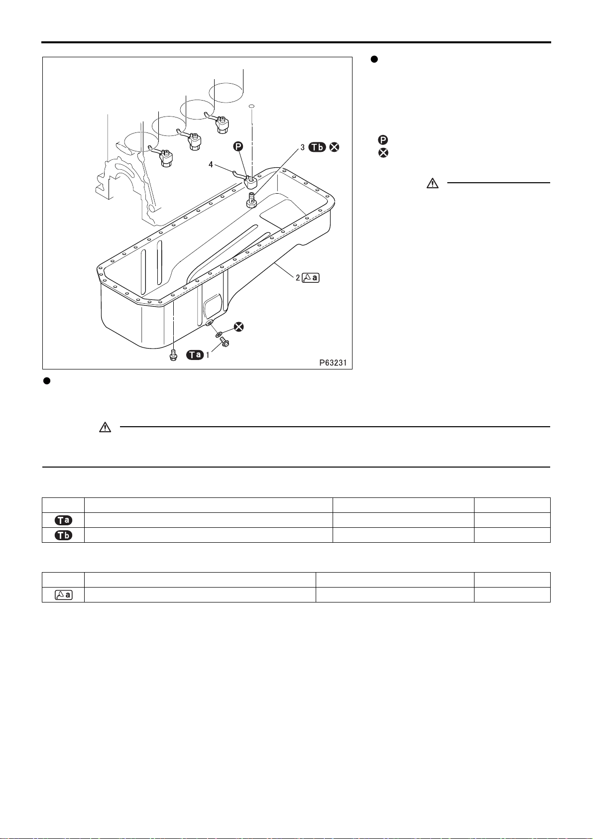
12-16
Disassembly sequence
1 Drain plug
2 Oil pan
3 Check valve
4 Oil jet
: Locating pin
: Non-reusable parts
CAUTION
• The check valve has been tightened
using thread-locking compound
and so, may deform during remov-
al. Once removed, the check valve
must not be reused. Do not remove
the check valve unless defects are
evident.
Assembly sequence
Follow the disassembly sequence in reverse.
CAUTION
• If overtightened, the check valve will not operate properly, leading to engine seizure. Be sure to tighten
the check valve to the specified torque.
Tightening torque (Unit: N·m {kgf·m})
Lubricant and/or sealant
Mark Parts to be tightened Tightening torque Remarks
Drain plug 68 {7} –
Check valve 34 {3.5} –
Mark Points of application Specified lubricant and/or sealant Quantity
Crankcase mounting surface of oil pan ThreeBond 1207C As required
M
ITSUBISHI 6M70 OIL JETS, OIL PAN,
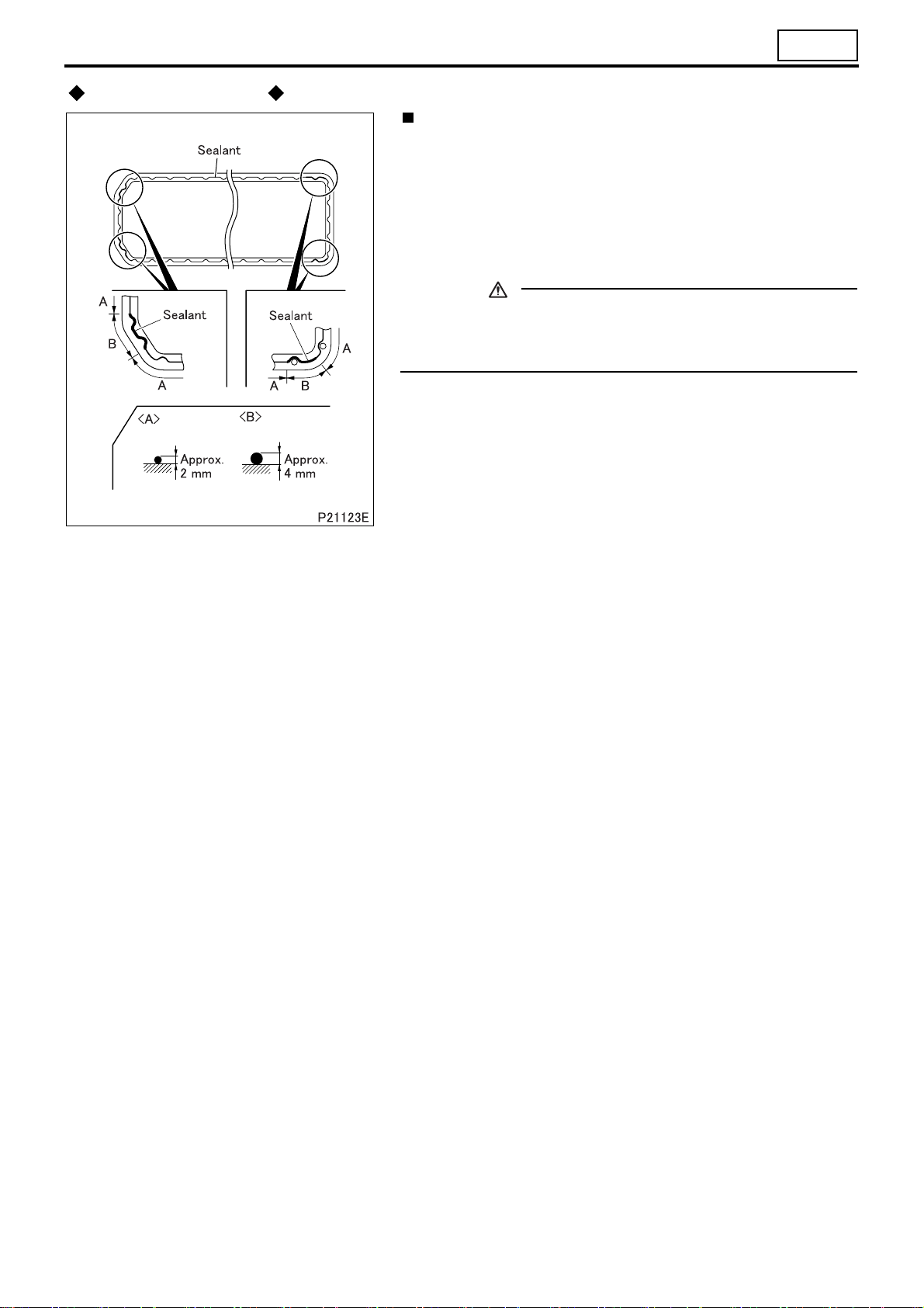
12
12-17
Installation procedure
Installation: Oil pan
• Clean the mating surfaces of each part.
• Apply a bead of sealant to the mating surface of the oil pan
evenly and without any breaks.
Change the amount of application to A and B at four locations
shown in the illustration.
• Mount the oil pan within three minutes of applying the sealant.
Make sure that the sealant stays in place.
CAUTION
• Do not start the engine less than an hour after installation. If
the oil pan mounting bolts were loosened or removed, be
sure to reapply sealant.
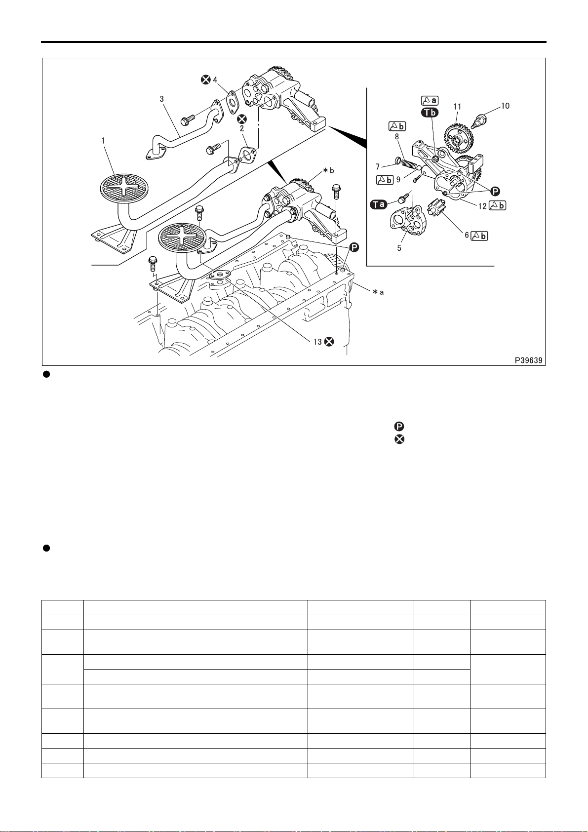
12-18
Disassembly sequence
• The oil strainer, the oil pipe and the oil pump must all be removed together as an assembly.
• Do
not disassemble the oil pump unless defects are evident.
• The gear and case assembly is not serviceable. If the gear and case assembly appears defective, replace it.
Assembly sequence
Follow the disassembly procedure in reverse.
Service standards (Unit: mm)
Location Maintenance item Standard value Limit Remedy
5, 12 Clearance between drive gear shaft and cover 0.04 to 0.07 0.15 Replace
5, 6, 12
Clearance between driven gear shaft and case, and
that between the shaft and cover
0.04 to 0.07 0.15 Replace
6, 12
Clearance between case and tooth tips of each gear 0.2 to 0.29 0.35
Replace
Difference between case depth and height of each gear 0.05 to 0.12 0.15
8 Relief valve spring installed load (installed length 47.7)
190 ± 11 N
{19.4 ± 1.1 kgf}
179 N
{18.3 kgf}
Replace
9 Relief valve opening pressure
0.9 MPa
{9 kgf/cm
2
}
0.9 MPa
{9 kgf/cm
2
}
Replace
10, 11 Clearance between idler shaft and idler gear 0.03 to 0.06 0.15 Replace
11,
*
a Backlash between idler gear and crankshaft gear 0.08 to 0.2 0.35 Replace
11,
*
b Backlash between idler gear and oil pump gear 0.076 to 0.196 0.35 Replace
1 Oil strainer
2 Gasket
3 Oil pipe
4 Gasket
5 Cover
6 Driven gear
7 Ring
8 Relief valve spring
9 Relief valve
10 Idler shaft
11 Idler gear
12 Gear and case
13 Gasket
*
a: Crankshaft gear
*
b: Oil pump gear
: Locating pin
: Non-reusable parts
+0.1
0
+1
0
M
ITSUBISHI 6M70 OIL PUMP, OIL STRAINER
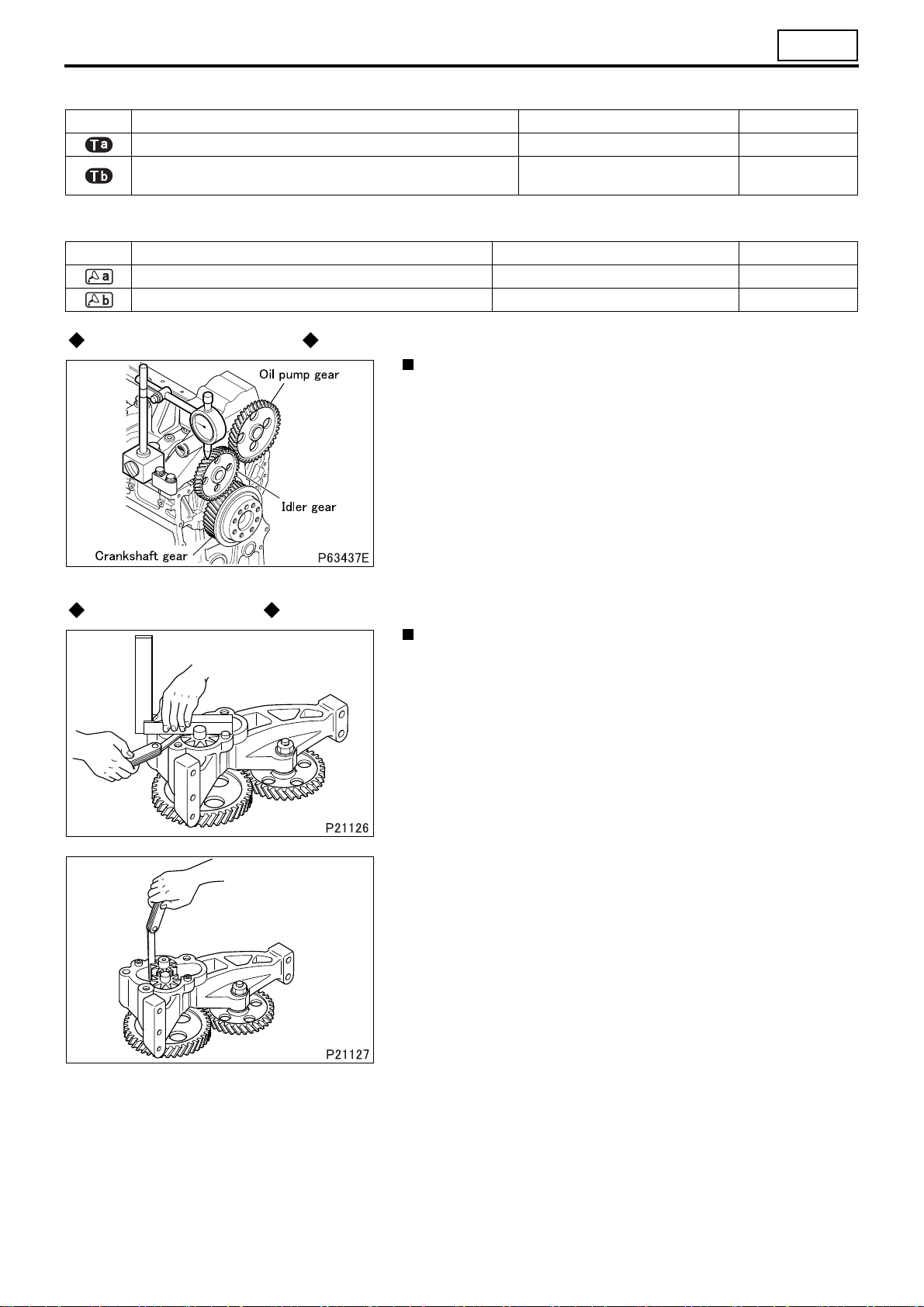
12
12-19
Tightening torque (Unit: N·m {kgf·m})
Lubricant and/or sealant
Inspection before removal
Inspection: Backlash of each gear
• If the measurement exceeds the limit, replace the defective
part(s).
Inspection procedure
Inspection: Driven gear, Gear and case assembly
• Perform the following inspections. Replace the defective part(s)
as required.
(1) Difference between case depth and height of each gear
(2) Clearance between case and tooth tips of each gear
Mark Parts to be tightened Tightening torque Remarks
Bolt (oil pump cover mounting) 44 ± 4.9 {4.5 ± 0.5} –
Nut (idler shaft mounting) 69 ± 10 {7 ± 1}
Thread-locking
compound
Mark Points of application Specified lubricant and/or sealant Quantity
Nut thread Loctite 262 As required
Sliding parts of oil pump Engine oil As required
M
itsubishi 6M70 Engine Parts contact:
email: [email protected]
Phone: 269 673 1638
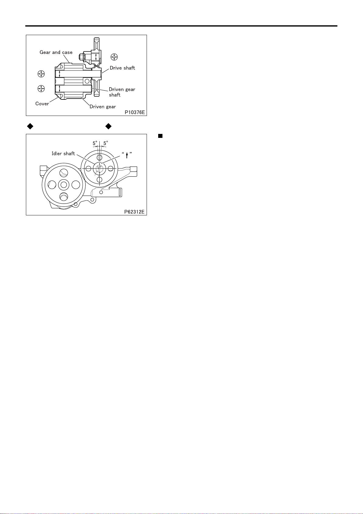
12-20
(3) Clearance between drive gear shaft and cover
(4) Clearance between driven gear shaft and case, and that
between the shaft and cover
Installation procedure
Installation: Idler shaft
• Install the idler shaft so that “↑” is positioned within the area
shown in the illustration.
OIL PUMP, OIL STRAINER

M E M O
12-21
12
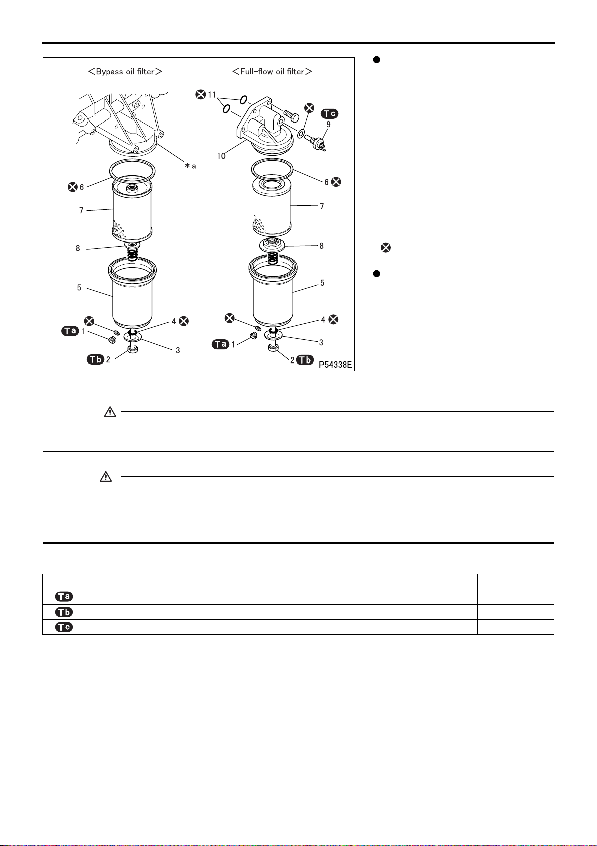
12-22
Disassembly sequence
1 Drain plug
2 Center bolt
3 Washer
4 O-ring
5 Oil filter case
6 Gasket
7 Oil filter element
8 Spring
9 Engine oil bypass alarm switch
10 Oil filter head
11 O-ring
*
a: Oil cooler
:
Non-reusable parts
Assembly sequence
Follow the disassembly sequence in re-
verse.
WARNING
• Wipe up any spilled engine oil, as it can cause fires.
• To avoid any risk of burns, take care not to touch the engine oil when the engine is hot.
CAUTION
• When adding engine oil, be careful not to allow engine oil to smear the belt. A belt smeared with oil will
slip, resulting in reduced cooling efficiency.
• Do not reuse the oil filter elements by washing.
• Install the gasket, taking care not to twist it.
Tightening torque (Unit: N·m {kgf·m})
Mark Parts to be tightened Tightening torque Remarks
Drain plug 24.5 ± 4.9 {2.5 ± 0.5} –
Center bolt 63.7 ± 4.9 {6.5 ± 0.5} –
Engine oil bypass alarm switch 49 ± 4.9 {5.0 ± 0.5} –
OIL FILTER

M E M O
12-23
12
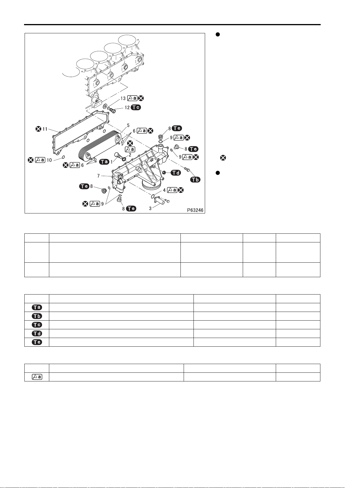
12-24
Removal sequence
1 Bypass valve
2 O-ring
3 Water pipe
4 O-ring
5 Oil cooler element
6 O-ring
7 Oil cooler cover
8 Oil cooler plug
9 O-ring
10 O-ring
11 Gasket
12 Regulator valve
(See later section.)
13 O-ring
: Non-reusable parts
Installation sequence
Follow the removal sequence in reverse.
Service standards (Unit: mm)
Tightening torque (Unit: N·m {kgf·m})
Lubricant and/or sealant
Location Maintenance item Standard value Limit Remedy
1 Bypass valve opening pressure
294 ± 50 kPa
{3.0 ± 0.5 kgf/cm
2
}
244 kPa
{2.5 kgf/
cm
2
}
Replace
5
Air leakage from oil cooler element
(air pressure: 1.47 MPa {15 kgf/cm
2
}, 15 seconds)
0 cm
3
{0 mL} – Replace
Mark Parts to be tightened Tightening torque Remarks
Bypass valve 15 to 20 {1.5 to 2.0} –
Bolt (oil cooler cover mounting) 54 {5.5} –
Regulator valve 98 to 118 {10 to 12} –
Nut (oil cooler element mounting) 24.5 to 32.3 {2.5 to 3.3} –
Oil cooler plug 21 {2.1} –
Mark Points of application Lubricant and/or sealant Quantity
O-ring Engine oil As required
M
ITSUBISHI 6M70 OIL COOLER
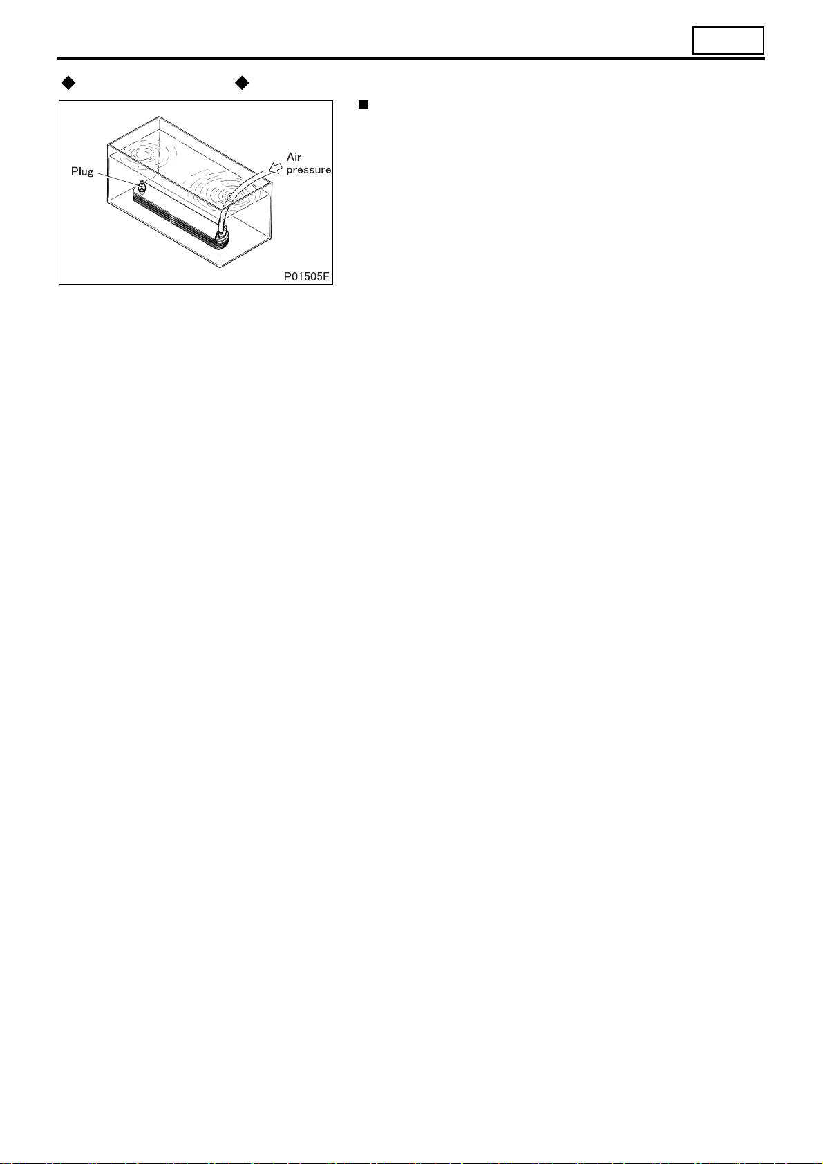
12
12-25
Inspection procedure
Inspection: Oil cooler element
• Plug the outlet of the oil cooler element and connect a hose to
the engine oil inlet port. Then, immerse the oil cooler element in
a tank of water.
• Apply a specified air pressure for 15 seconds through the hose,
and check for any air leaks.
• Replace the element if it leaks air.
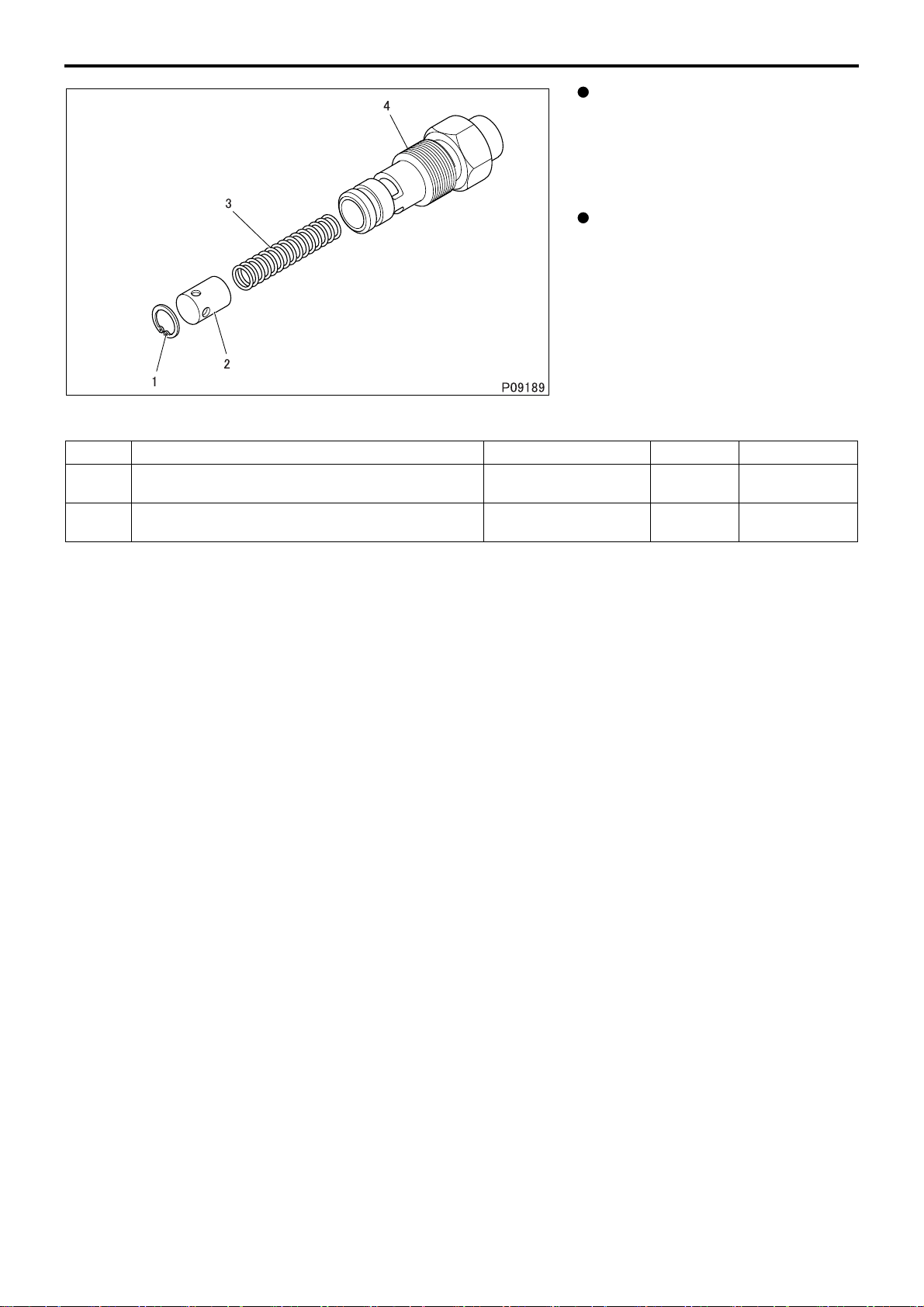
12-26
Disassembly sequence
1 Snap ring
2 Valve
3 Spring
4 Body
Assembly sequence
Follow the disassembly sequence in re-
verse.
Service standards (Unit: mm)
Location Maintenance item Standard value Limit Remedy
– Regulator valve opening pressure
0.49 ± 0.03 MPa
{5.0 ± 0.3 kgf/cm
2
}
–Replace
3 Spring installed load (installed length 48.3)
78 ± 2 N
{8.0 ± 0.2 kgf}
–Replace
M
ITSUBISHI 6M70 REGULATOR VALVE

13-1
GROUP 13
FUEL AND ENGINE CONTROL
SPECIFICATIONS................................. 13-2
STRUCTURE AND OPERATION
1. Common Rail System ....................... 13-4
2. Engine Control ................................ 13-20
3. Fuel Filter ......................................... 13-21
4. Water Separator............................... 13-22
TROUBLESHOOTING
<FUEL SYSTEM> ............................... 13-24
<DIAGNOSIS USING Multi-Use Tester>
1. Diagnosis Procedure ...................... 13-26
2. Diagnostic Precautions .................. 13-27
3. Inspections Based on
Diagnosis Codes .............................
13-28
4. Multi-Use Tester Service Data ........ 13-50
5. Actuator Tests Performed
Usin
g Multi-Use Tester....................
13-52
6. Inspections Performed at Electronic
Control Unit
Connectors ................
13-54
ON-VEHICLE INSPECTION AND
ADJUSTMENT
1. Inspecting No-load Minimum
and Maximum Speeds
.................... 13-58
2. Inspection of Fuel Leakage ............ 13-59
3. Inspection of Injection Pipe and
Fu
el Pipe Mounting Clamp
............. 13-59
4. Draining of Deposit in Fuel Tank.... 13-59
5. Air-bleeding of Fuel System........... 13-60
6. Fuel Filter Replacement................. 13-61
7. Cleaning of Gauze Filter ................ 13-62
8. Water Separator Element
Repl
acement....................................
13-63
COMMON RAIL................................... 13-65
SUPPLY PUMP.................................... 13-66
INJECTOR........................................... 13-70
FUEL TANK......................................... 13-74
FUEL FILTER ...................................... 13-76
WATER SEPARATOR ......................... 13-80
ENGINE CONTROL ............................ 13-84
INSPECTION OF ELECTRICAL
EQUIPMENT........................................ 13-88
INSTALLED LOCATIONS OF
PARTS ................................................. 13-94
ELECTRIC CIRCUIT DIAGRAM ....... 13-102

13-2
Item Specifications
Supply pump
Manufacturer Bosch
Model CP2L4
Control method Electronic
Type In-Line 4 barrel type
Feed pump type External gear
Rail pressure
control valve
Model MPROP
Rated voltage V 24
Max. common rail pressure
MPa {kgf/cm
2
}
160 {1631}
Common rail
Manufacturer Bosch
Common rail volume cm
3
{mL} 20 {20}
Pressure limiting valve opening pressure
MPa {kgf/cm
2
}
185 to 195 {1886 to 1988}
Common rail pressure sensor supply
voltage V
5
Injectors
Manufacturer Bosch
Control method Electronic
Max. operating pressure
MPa {kgf/cm
2
}
160 {1631}
Min. operating pressure
MPa {kgf/cm
2
}
25 {255}
Common rail
electronic control
unit
Manufacturer Bosch
Rated voltage V 24
M
ITSUBISHI 6M70 FUEL SYSTEM SPECIFICATIONS
Mitsubishi 6M70 Engine Parts contact:
email: [email protected]
P
hone: 269 673 1638

M E M O
13-3
13
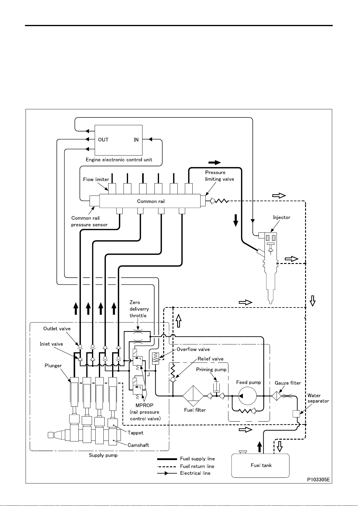
13-4
1. Mitsubishi 6M70 Common Rail System
• In the common rail system, an electronic control unit monitors various aspects of the engine (engine speed, accel-
erator position coolant temperature, etc.) using information from sensors. In accordance with these data, the elec-
tronic control unit effects control over the fuel injection quantity, fuel injection timing, and fuel injection pressure in
order to optimize the engine’s operation.
• The electronic control unit has a diagnosis function that enables it to recognize abnormalities in the common rail
system’s major components and alert the driver to them.
• The common rail system consists mainly of an electronically controlled supply pump; injectors; a common rail;
and the electronic control unit and sensors that are used to control the other components.
STRUCTURE AND OPERATION

13
13-5
• When the engine is cranked by means of the starter switch, the feed pump (this is located inside the supply pump)
simultaneously draws fuel from the fuel tank and feeds it via the water separator, gauze filter and fuel filter to the
MPROP (rail pressure control valve). A quantity of fuel metered by the MPROP is supplied via the inlet valves to
the plunger chambers.
• The fuel in the plunger chambers is pressurized. The outlet valves are then opened, and the fuel is fed under
pressure to the common rail.
• The pressurized fuel is held in the common rail and then uniformly fed to the injectors.
• In response to signals from the engine electronic control unit, a magnetic valve in each injector causes the injector
to inject fuel into the relevant combustion chamber at the optimal timing and in the optimal quantity.
• If fuel leakage occurs through any of the fuel line connections between the common rail and injectors, the relevant
flow limiter(s) will close, shutting off fuel supply and thus preventing any further fuel leakage out of the system.
• If the pressure of fuel in the common rail rises above the specified level, the pressure limiting valve opens to allow
fuel to return to the fuel tank.
• If the pressure of fuel in the supply pump rises above the specified level, the overflow valve opens to allow fuel to
return to the fuel tank.
• Excess fuel in the injector returns to the fuel tank through passages in the cylinder head.
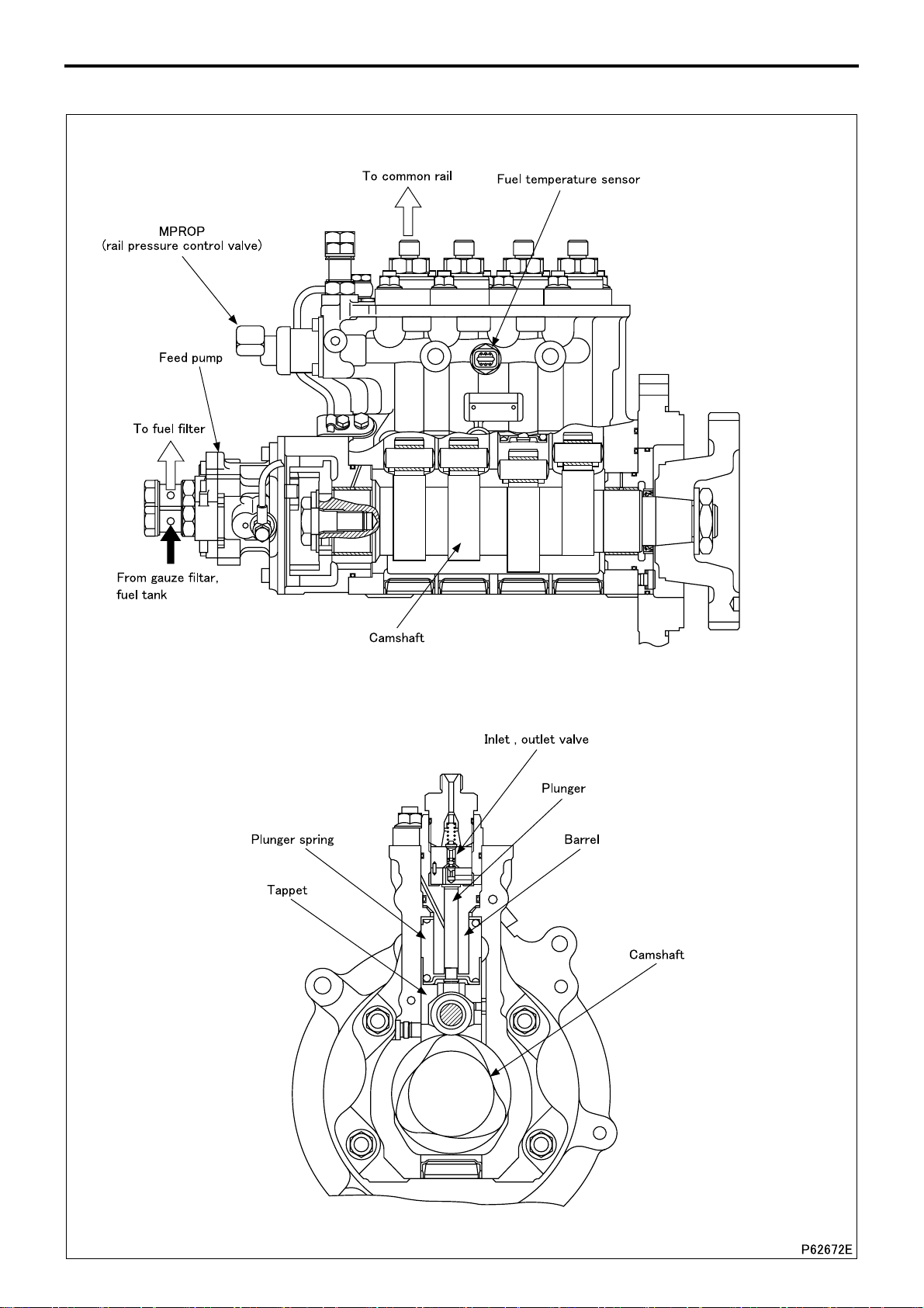
13-6
1.1 Mitsubishi 6M70 Supply pump
STRUCTURE AND OPERATION
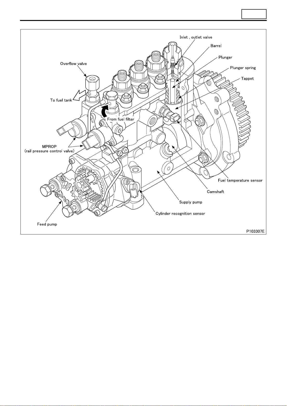
13
13-7
• The supply pump pressurizes fuel and supplies it in a highly pressurized state.
• Fuel drawn from the fuel tank by the feed pump is not supplied directly to the plungers. It is supplied first to the
MPROP (rail pressure control valve), which controls the amount of fuel reaching the plungers.
• If the fuel pressure exceeds a certain level, the overflow valve returns fuel to fuel tank. This operation keeps the
pressure of the fuel constant.
• Rotation of the camshaft causes (via the tappets) up-down movement of the plungers. Fuel in the plunger cham-
bers is thus highly pressurized.
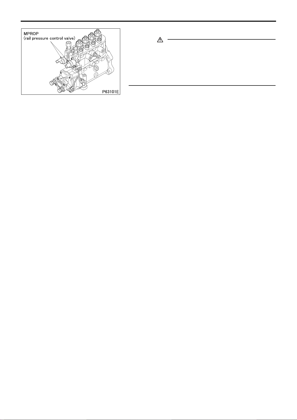
13-8
(1) MPROP (rail pressure control valve)
CAUTION
• Be sure to connect the MPROP (rail pressure control valve)
connector to the engine harness before starting the engine.
If the engine were started with the MPROP connector not
connected, control of the supply pump by the engine elec-
tronic control unit would not be possible and a fault would
ensue.
• The MPROP receives fuel from the feed pump and feeds fuel to-
ward the plungers of the supply pump in such a quantity that the
fuel pressure (target common rail pressure) corresponds to that
required by the engine electronic control unit.
• When the MPROP is not operating, i.e., when current is not flow-
ing, fuel flows at its maximum rate. When current flows, the pis-
ton in the MPROP is pressed down such that fuel is not fed
toward the plungers.
• The engine electronic control unit controls the ratio of current-off
time (duty ratio).
STRUCTURE AND OPERATION
M
itsubishi 6M70 Engine Parts contact:
email: [email protected]
Phone: 269 673 1638
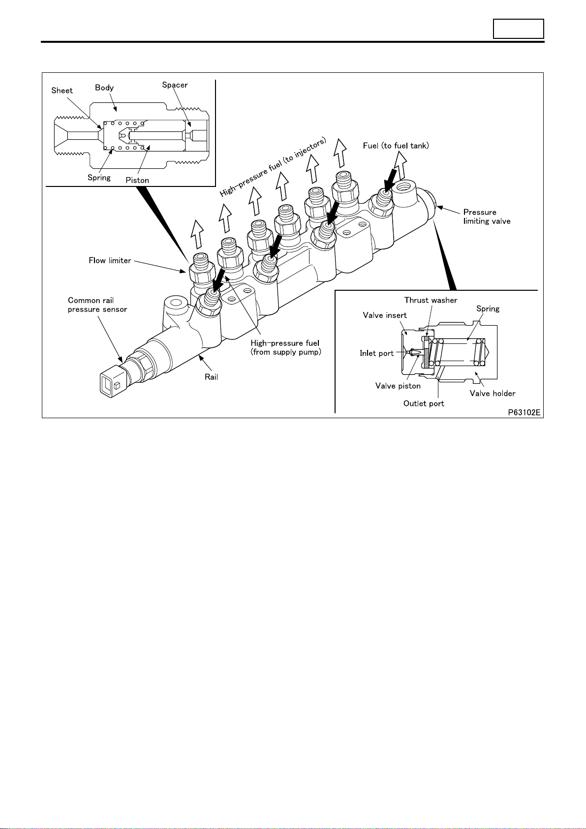
13
13-9
1.2
Mitsubishi 6M70 Common rail
• The common rail distributes to the injectors high-pressure fuel that has been fed from the supply pump.
• Each flow limiter prevents an abnormal outflow of fuel. It does so by blocking the fuel passage in the event of fuel
leakage from the injection pipe or excessive injection of fuel from the injector.
• The common rail pressure sensor is used in feedback control. It senses the fuel pressure (actual common rail
pressure) inside the common rail and feeds a corresponding signal to the electronic control unit.
• If the fuel pressure in the common rail exceeds a certain, set level, the piston in the pressure limiting valve pushes
and compresses the spring such that fuel is able to escape. The pressure limiting valve thus prevents the fuel
pressure from becoming higher than the set pressure. When the pressure limiting valve is activated, the common
rail system is faulty and needs an inspection of fuel supply system.
(1) Flow limiter
• During normal operation, the piston moves (thus pushing and compressing the spring) to the extent necessary for
one injection quantity to pass through. The piston does not make contact with the seat at this time. When injection
is complete, the piston is returned to its initial position by the spring.
• If the amount of fuel passing through the flow limiter becomes excessively great, the piston presses against the
seat, thereby closing the fuel passage and preventing an abnormal outflo
w of fuel.
When the piston has pressed against the seat, it does not return to its original position until the engine has been
stopped and the pressure in the common rail has come down.
Mitsubishi 6M70 Engine Parts contact:
email: [email protected]
Phone: 269 673 1638
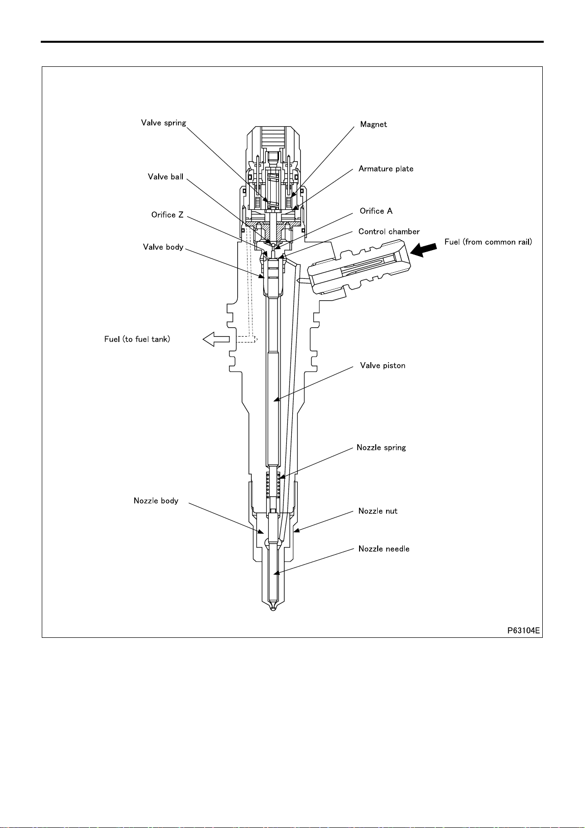
13-10
1.3 Mitsubishi 6M70 Injector
• In ac
cordance with electrical signals from the engine electronic control unit, each injector supplies high-pressure
fuel from the common rail to the relevant combustion chamber of the engine at the optimal timing and in the opti-
mal quantity.
• The Mitsubishi 6M70 injector is divided into the control section and the injector section.
• The control section consists of the control chamber, magnet, valve spring, armature plate, valve ball, valve
body, valve piston, orifice A, and orifice Z. The valve piston is located between the control section and the injec-
tion section.
• The injection section consists of the nozzle body, nozzle needle, nozzle spring, and nozzle nut.
STRUCTURE AND OPERATION
Mits
ubishi 6M70 Engine Parts contact:
email: [email protected]
Phone: 269 673 1638
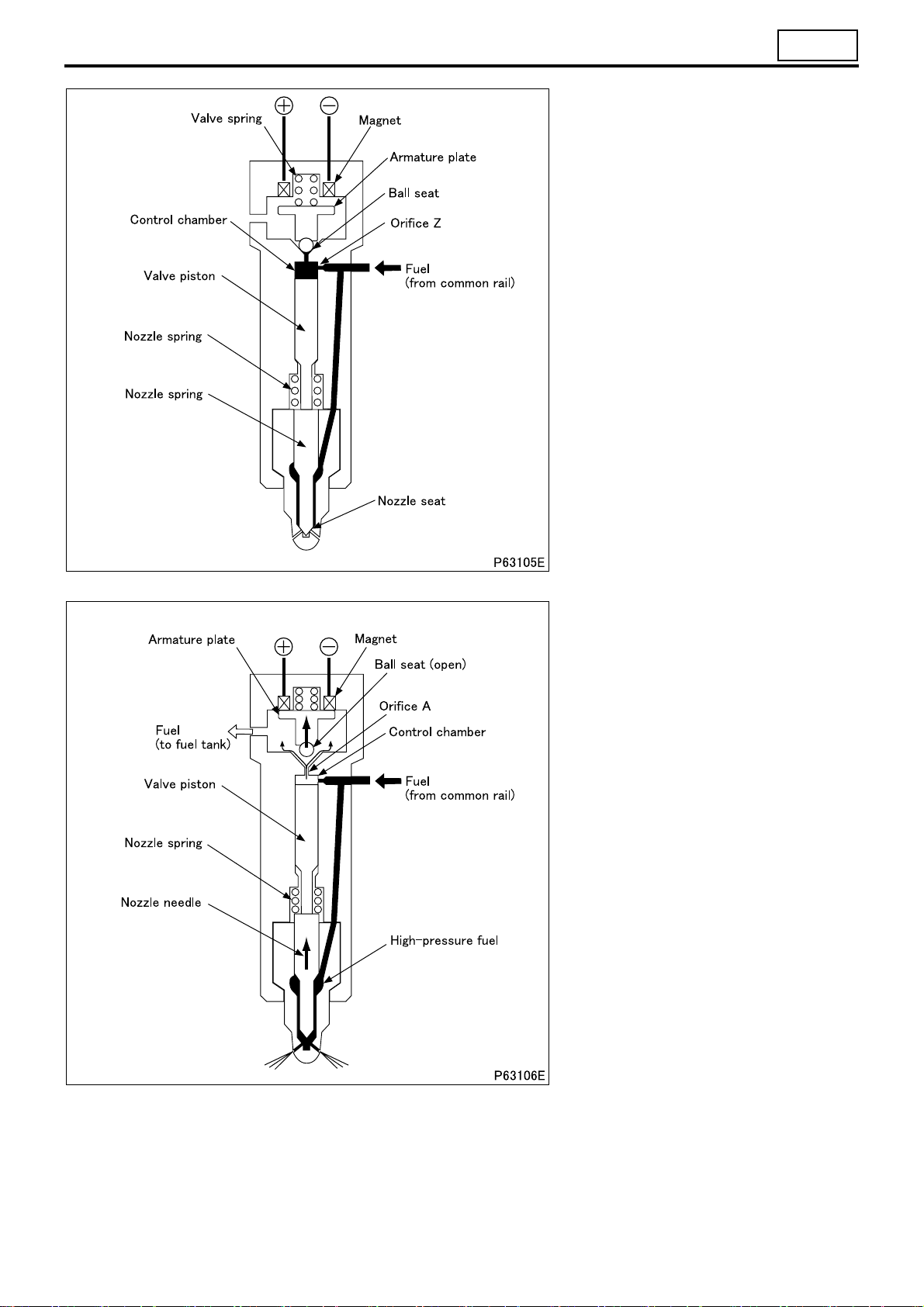
13
13-11
(1) Operation
(1.1) Injection not taking place
• With the magnet not energized, the ar-
mature plate is pushed down by the
valve spring such that the ball seat is
closed.
• The high-pressure fuel acts upon the
control chamber via orifice Z. The
same pressure acts upon the nozzle
needle.
• The fuel pressure acting on the nozzle
needle cannot overcome the valve pis-
ton and nozzle spring, so the nozzle
needle stays in its downward-pushed
position and injection does not take
place.
(1.2) Start of injection
• When the magnet is energized, the re-
sulting electromagnetic force draws
the armature plate upward, causing
the ball seat to open.
• Fuel in the control chamber passes
through the orifice A and ball seat and
flows to the fuel tank.
• With the pressure in the control cham-
ber reduced, the fuel acting on the
nozzle needle overcomes the valve
piston and nozzle spring, pushing up
the nozzle needle such that injection
starts.
• If the magnet remains energized, the
injection reaches its maximum level.
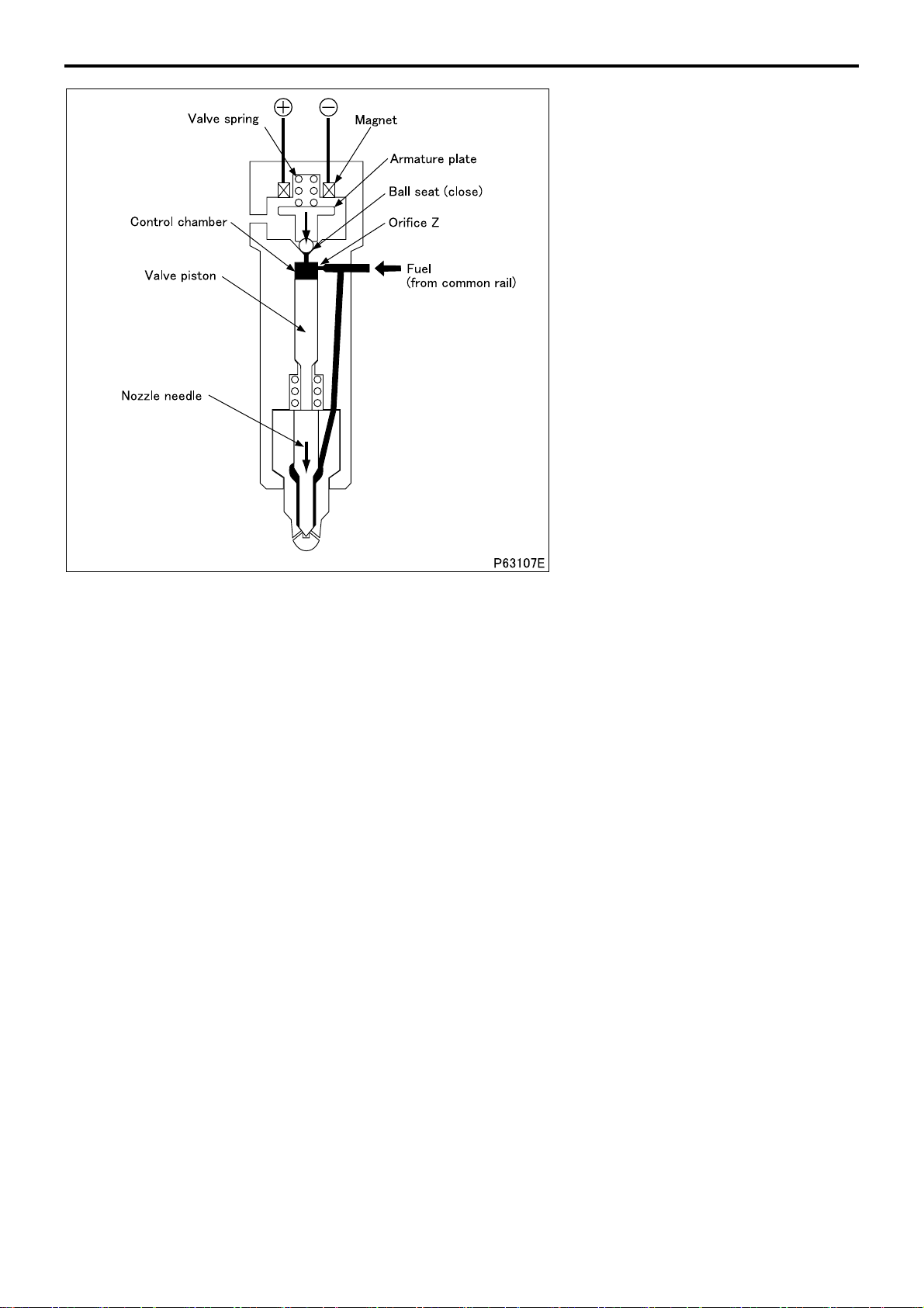
13-12
(1.3) End of injection
• When energization of the magnet is
stopped, the armature plate is pushed
downward by the valve spring such
that the ball seat closes. At this time,
fuel flows into the control chamber via
orifice Z, pushing down the valve pis-
ton and nozzle needle such that injec-
tion finishes.
STRUCTURE AND OPERATION
M
itsubishi 6M70 Engine Parts contact:
em
ail: [email protected]
Phone: 269 673 1638
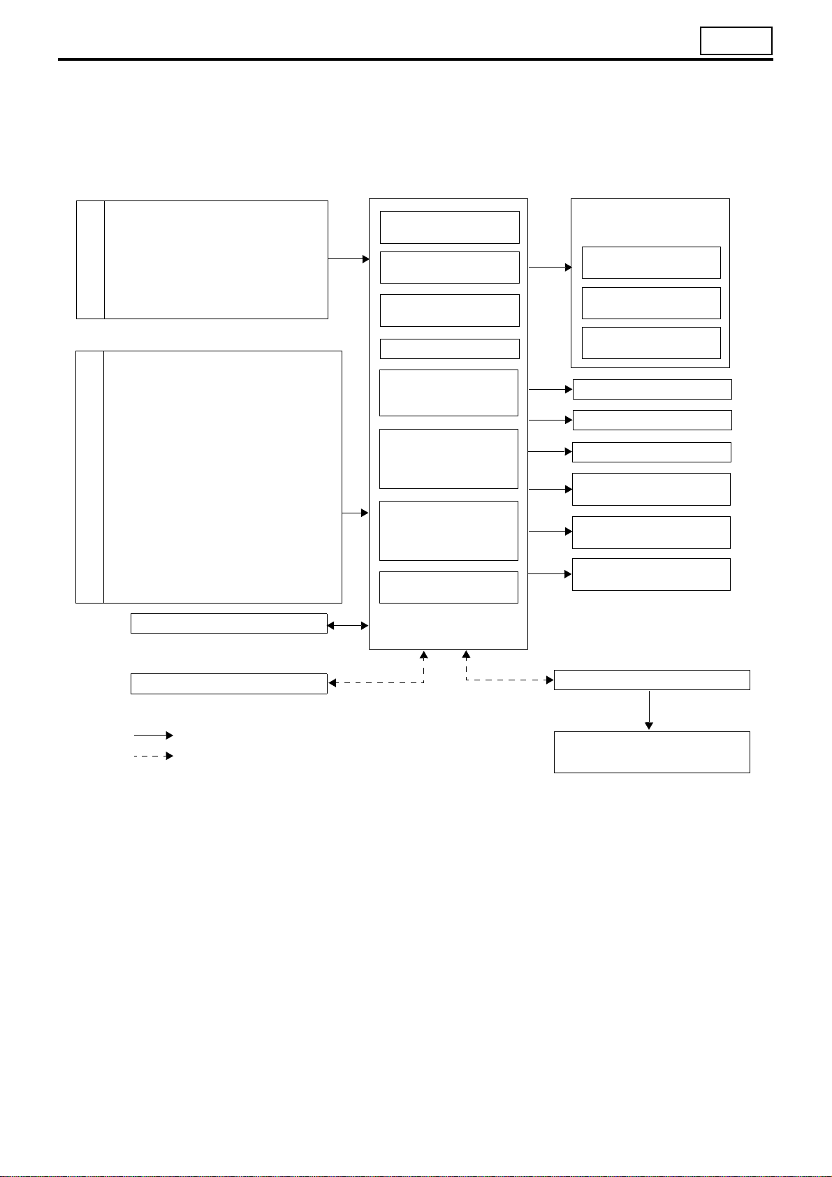
13
13-13
1.4 Electronic control system
(1) System block diagram
Fuel injection timing
control
Input signals
Engine electronic control unit
Output signals
Engine
Engine speed sensor
Cylinder recognition sensor
Water temperature sensor
Boost pressure sensor
Common rail pressure sensor
Fuel temperature sensor
Intake air temperature sensor
Vehicle
Starter switch
Accelerator pedal position sensor
Accelerator pedal switch
Pulse converter (vehicle speed sensor)
Idling speed adjustment potentiometer
Fuel injection rate adjustment resistor
Clutch switch
Transmission neutral switch
Powertard switch
Memory clear switch
Diagnosis switch
Governor control switch
Power take-off resistor
Power take-off load sensor
Pulse converter & Turbine speed sensor
Fuel injection control
Warm-up acceleration
function
Exhaust gas
recirculation valve
control function
(See Gr17.)
Starter continuous
energization
prevention function
(See Gr54.)
Fault diagnosis
function
Injector magnetic valve
MPROP1, 2 (rail pressure
control valve)
Fuel injection
pressure control
Fuel injection quantity
control
Tachometer
Safety relay
Electronic drive
unit relay
Auxiliary brake
function
Idle-up function
Turbocharger control
function
(See Gr15.)
Powertard
solenoid valve
Turbocharger
magnetic valve
ABS: Anti-lock brake system
ASR: Anti spin regulator
CAN: Controller area network
ECU: Electronic control unit
EDU: Electronic drive unit
EGR:Exhaust gas recirculation
MVCU: Multifunction vehicle control unit
MVCU (See Gr54.)
Multi-Use Tester connector
EGR EDU (See Gr17.)
: Electrical signal
: CAN signal
Engine warning lamp
EGR magnetic valve
(See Gr17.)

13-14
EGR: Exhaust gas recirculation
EDU: Electronic drive unit
MVCU: Multifunction vehicle control unit
M
itsubishi 6M70 Parts Main function/operation
Engine speed sensor Sensing of engine speed
Cylinder recognition sensor Cylinder recognition
Water temperature sensor Sensing of coolant temperature
Boost pressure sensor Sensing of boost pressure
Common rail pressure sensor Sensing of common rail pressure
Fuel temperature sensor Sensing of fuel temperature
Intake air temperature sensor Sensing of intake air temperature
Starter switch
Senses that the engine is in starting condition with the starter switch in
START position.
Accelerator pedal position sensor Sensing of extent of accelerator pedal depression
Accelerator pedal switch
Sensing of released/pressed condition of accelerator pedal (ON with
pedal released)
Pulse converter (vehicle speed sensor) Sensing of vehicle speed
Idling speed adjustment potentiometer Acceleration of warm-up
Fuel injection rate adjustment resistor Correction of fuel injection rate
Clutch switch
Sensing of released/Pressed condition of clutch pedal (OFF with pedal
released)
Transmission neutral switch Detection of transmission neutral condition
Powertard switch Operation of auxiliary brake
Diagnosis switch Output of diagnosis codes
Memory clear switch Deletion of diagnosis codes; output of past diagnosis codes
Governor control switch Idle up when power take-off is in operation
Power take-off resistor Selection of power take-off map
Power take-off load sensor Sensing of extent of accelerator pedal depression
Pulse converter & Turbine speed sensor Sensing of turbine wheel speed
Injector magnetic valve
Control of fuel injection rate, fuel injection quantity, and fuel injection
timing
MPROP1, 2 (rail pressure control valve) Control of fuel injection pressure
Engine warning lamp Indication of system abnormalities
Tachometer Indication of engine speed (in meter cluster)
Powertard solenoid valve ON/OFF control of Powertard magnetic valve
Turbocharger magnetic valve Selection of turbocharger control
Safety relay Control of starter continuous energization prevention function
Electronic drive unit relay Supply of power to exhaust gas recirculation electronic drive unit
CAN communication
(MVCU)
Engine data recognized by the engine electronic control unit are output-
ted to the CAN bus to enable systems to obtain data that they need for
control. Multifunction Vehicle Control Unit system issues signals to the
engine electronic control unit via the CAN bus to enable it to effect en-
gine control appropriate for type of system control.
Multi-Use Tester connector Communication between Multi-Use Tester and common rail system
CAN communication
(EGR EDU)
Engine data recognized by the engine electronic control unit are output-
ted to the CAN bus to enable systems to obtain data that they need for
control. Exhaust gas recirculation electronic drive unit issues signals to
the engine electronic control unit via the CAN bus to enable it to effect
engine control appropriate for type of system control.
STRUCTURE AND OPERATION
Mitsubishi 6M70 engine parts contact:
email:
phone: 269 673 1638
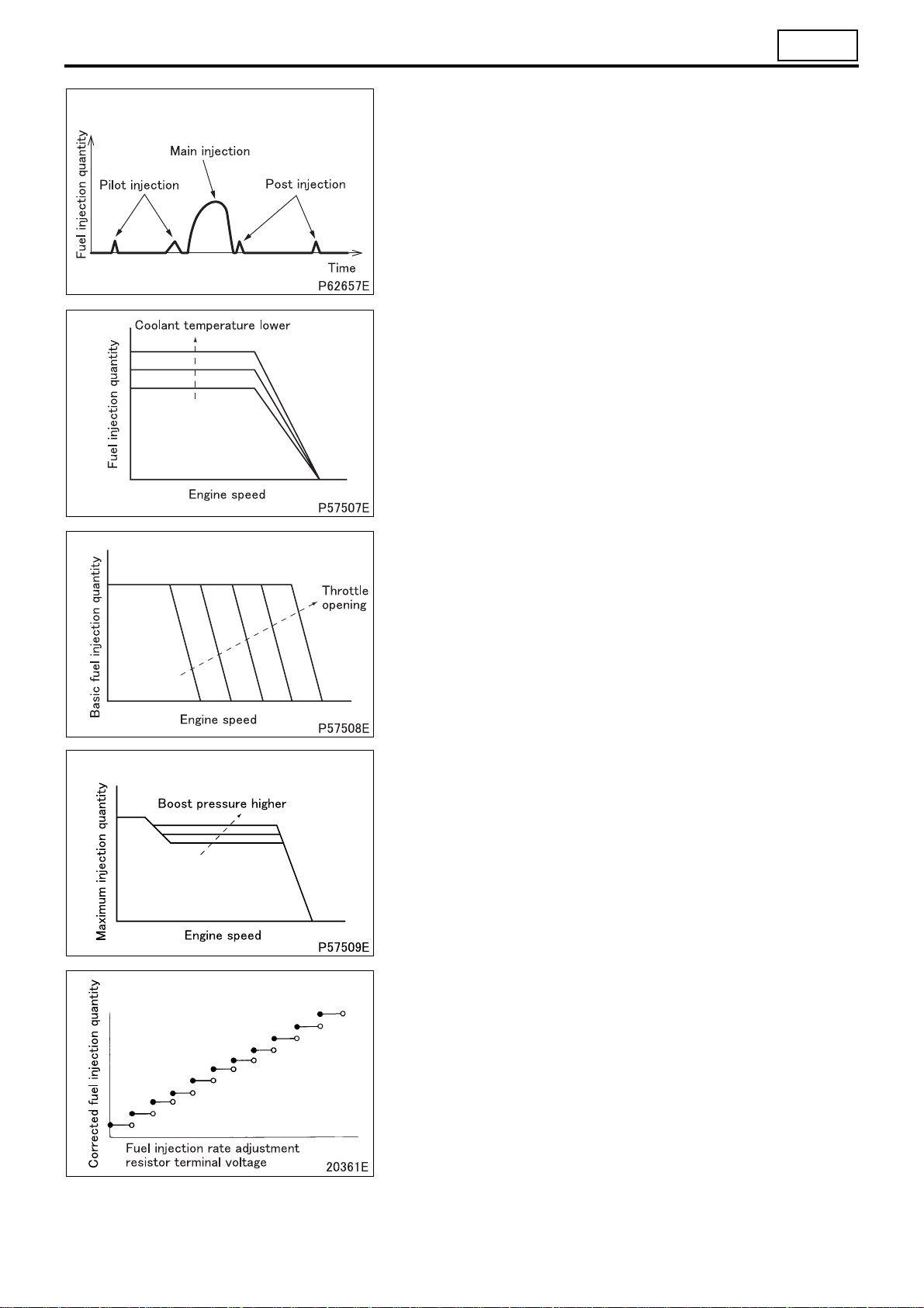
13
13-15
(2) Fuel injection control
(2.1) Pilot injection
• Pilot injection entails the injection of an extremely small amount
of fuel ahead of the main injection.
• This suppresses hasty heat generation early in the injection cy-
cle and thus suppresses NOx generation and noise at the start
of combustion.
• The post injection added after the main injection reduces partic-
ulate matter (PM) generation in the exhaust gas.
(3) Fuel injection quantity control
(3.1) Fuel injection quantity during engine startup
• During engine startup, the fuel injection quantity is determined in
accordance with the engine speed and coolant temperature.
(3.2) Basic fuel injection quantity
• The basic fuel injection quantity is determined in accordance
with the engine speed and throttle opening.
(3.3) Maximum injection quantity
• The maximum injection quantity is calculated from the engine
speed and boost pressure.
(3.4) Fuel injection rate adjustment resistor correction
amount
• To limit inconsistency in the injection quantity, the injection quan-
tity is corrected by the fuel injection rate adjustment resistor.
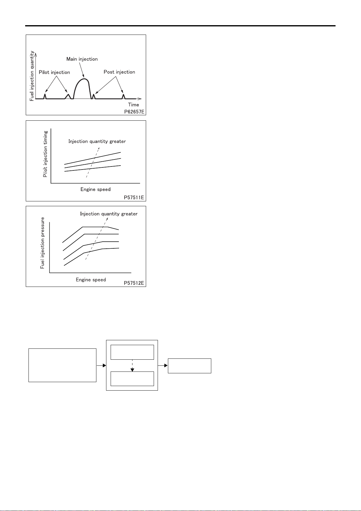
13-16
(4) Fuel injection timing control
(4.1) Main injection timing
• The main injection timing is calculated from the fuel injection
quantity and engine speed.
(4.2) Pilot injection timing (pilot interval)
• The pilot injection timing is calculated from the fuel injection
quantity and engine speed.
(5) Fuel injection pressure control
• The fuel injection pressure is calculated from the fuel injection
quantity and engine speed.
(6) Warm-up acceleration function
• The warm-up acceleration function increases engine warm-up by varying the engine’s idling speed in accordance
with the engine’s coolant temperature. It can operate either automatically or manually. Selection is made using the
idling speed adjustment potentiometer.
Water temperature sensor
Accelerator pedal position
sensor
Idling speed adjustment
potentiometer
Input signals
Engine electronic
control unit
Output signals
Comparison
operations
Target injection
quantity
Idling speed
control
STRUCTURE AND OPERATION

13
13-17
(7) Auxiliary brake function
• The auxiliary brake function activates or deactivates the Powertard solenoid valve according to the vehicle condi-
tion to control the auxiliary brake.
(8) Idle-up function
• The idle-up function increases the engine idling speed when a load is applied to the engine by other system or
when the warm-up acceleration function is activated.
(9) Fault diagnosis function
• When the starter switch is in the ON position, the system continuously monitors the sensors and other system
components. If any fault is detected, the system warns the driver of this by displaying the relevant fault information
on the meter cluster. At the same time, the system also stores a relevant diagnosis code in the memory and starts
operation in the fault mode.
• While the control during fault is taking place, the system’s functionality is limited to ensure vehicle and driver safe-
ty. It is possible to read the memorized diagnosis code using a Multi-Use Tester or from flashing of the warning
lamp.
• Diagnosis codes shown by the Multi-Use Tester and those indicated by flashing of the warning lamp are different.
• The Multi-Use Tester is capable of showing more detailed diagnosis codes.
Accelerator pedal position sensor
Clutch switch
Transmission neutral switch
Powertard switch
Auxiliary brake
function
Powetard solenoid valve
Engine electronic
control unit
Input signals
Output signals
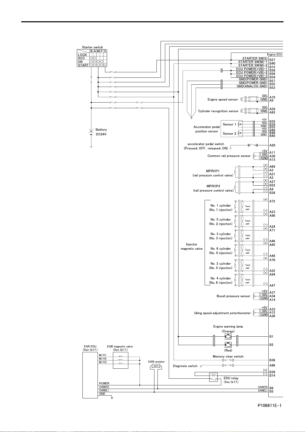
13-18
(10)Electronic control unit connection diagram
STRUCTURE AND OPERATION
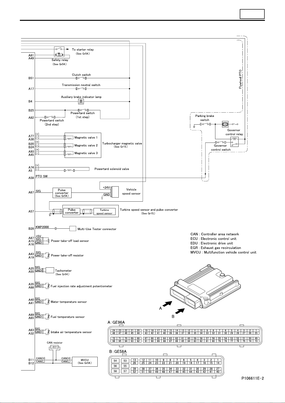
13
13-19
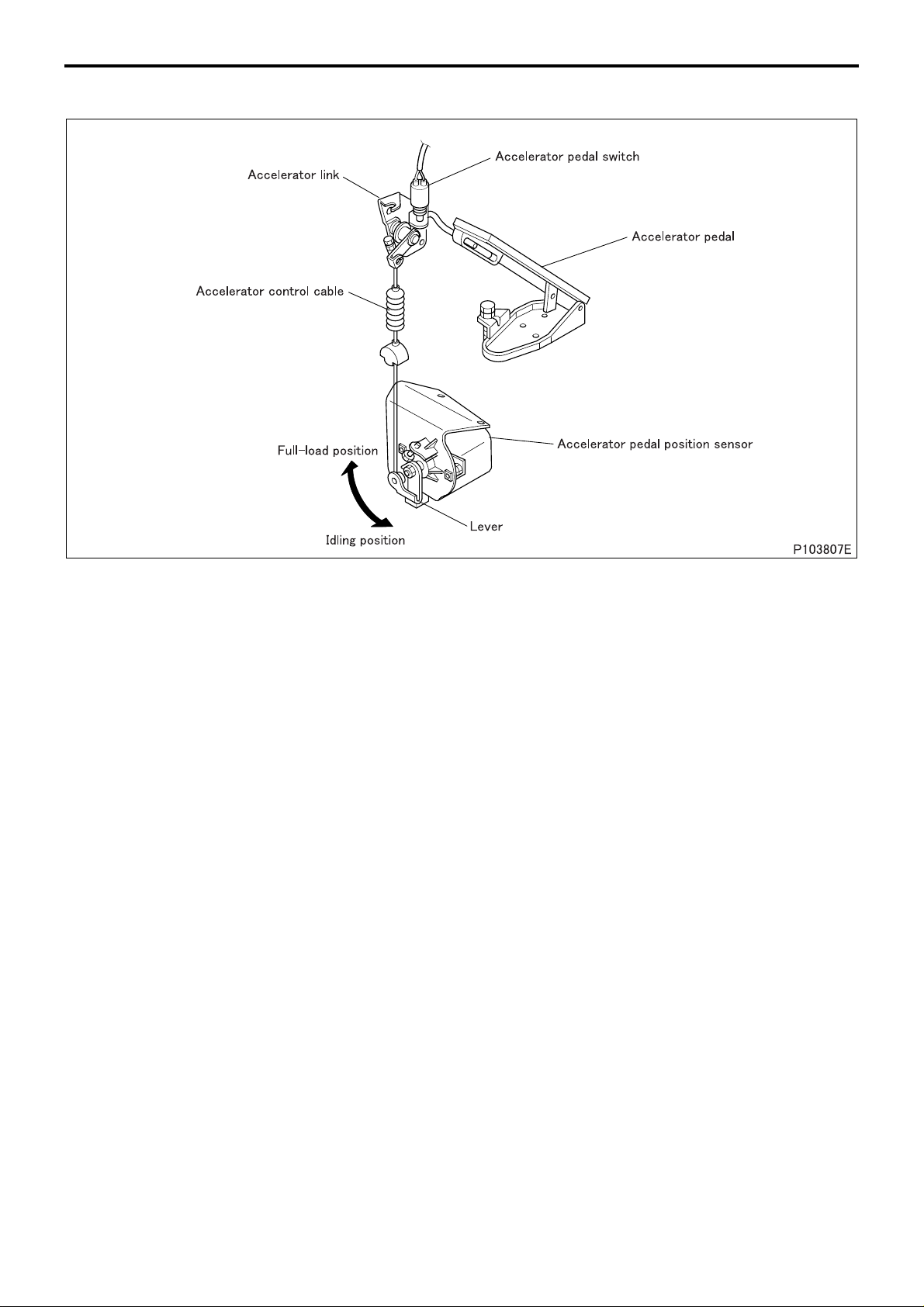
13-20
2. Engine Control
2.1 Accelerator pedal switch
• The accelerator pedal switch is used to monitor whether or not the accelerator pedal is pressed.
2.2 Accelerator pedal position sensor
• The accelerator pedal position sensor monitors for change in the position of the accelerator pedal and sends rele-
vant electric signals to the common rail electronic control unit. The lever is constantly pulled towards the idling po-
sition by a return spring.
STRUCTURE AND OPERATION
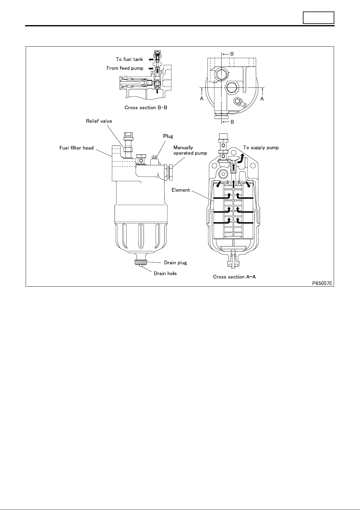
13
13-21
3. Fuel Filter
• The fuel filter removes foreign matter from fuel via the filter element. The fuel filter also incorporates a water sep-
arator which separates any water from fuel.
• Water separated from fuel accumulates at the bottom of the fuel filter assembly.
• The water which has collected can be drained through the drain hole by loosening the drain plug.
• To bleed air from the fuel system, a manually operated pump and plug are provided on the fuel filter head.
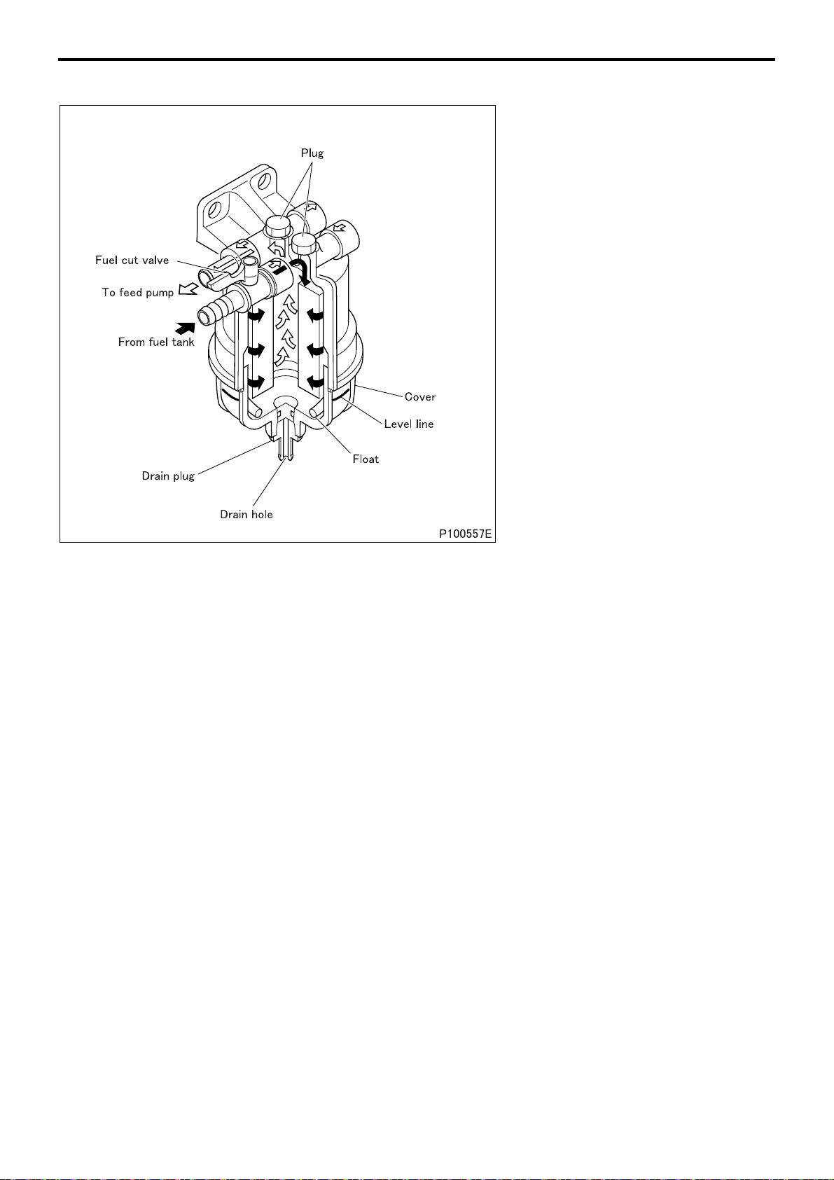
13-22
4. Water Separator
• A water separator is installed between
the fuel tank and the feed pump. It is
designed to remove impurities from
fuel and also separates water from fu-
el.
• Water separated from fuel is collected
at the bottom of the water separator
and is drained when the float reaches
the level line.
• To drain water collected, loosen the
drain cock. This allows the water to be
discharged through the drain hole.
STRUCTURE AND OPERATION

M E M O
13-23
13
13-24
MPROP: Rail pressure control valve
*
: Contact Bosch Service Station for repair.
Symptoms
Engine does not start
Engine hard to start
Engine knocks
Engine output inconsistent
Engine output not sufficient
Engine maximum speed too high
Engine idling unstable
Engine stalls immediately after start
Engine does not reach maximum speed
Engine does not stop
Fuel supply insufficient
Engine control warning lamp illuminates
Reference
Gr
Possible causes
Defective electronic control fuel system O
Supply pump
Defective feed pump O O O O
*
Defective sealing of supply pump overflow valve O O O O
*
Defective MPROP O O O O O
Defective base supply pump O O O O
*
Common rail
Common rail pressure sensor open-circuited,
short or intermittent connection; defective sensor
OO OO O O
Pressure limiting valve malfunction O O O
*
Incorrect injector
fuel injection
Defective injector magnetic valve O O O O O
Defective injector O O O O
*
Gauze filter clogged O O O O O O
Fuel filter clogged O O O O
Water separator clogged O O O O
No fuel in fuel tank O
Fuel pipe clogged and fuel leak from joint O
Air or water in fuel system O O O O
Poor quality fuel is used O O O O
Fuel leak from high-pressure joint O O O O O
Engine control
Incorrectly adjusted accelerator pedal stopper bolt O O
Defective accelerator position sensor O O O
Engine speed sensor and cylinder recognition sensor open-circuited,
short, or intermittent connection
OO O
Boost pressure sensor open-circuited, short, or intermittent connec-
tion
OOO O O
Water temperature sensor open-circuited, short, or intermittent con-
nection
OO O
Defective fuel injection volume adjusting resistor O O O
Idling speed adjustment knob intermittent connection O O O
Fuel pipe and hose cracked O
TROUBLESHOOTING <MITS
UBISHI 6M70 FUEL SYSTEM>
13
13-25
Symptoms
Engine does not start
Engine hard to start
Engine knocks
Engine output inconsistent
Engine output not sufficient
Engine maximum speed too high
Engine idling unstable
Engine stalls immediately after start
Engine does not reach maximum speed
Engine does not stop
Fuel supply insufficient
Engine control warning lamp illuminates
Reference
Gr
Possible causes
Oil viscosity unsuitable O O Gr12
Valve clearance incorrect O O
Gr11
Defective cylinder head gasket O O
Valve and valve seat worn and carbon deposits O O
Valve spring fatigued O O
Piston ring worn and damaged O O
Piston ring groove worn and damaged O
Piston and cylinder liner worn O O
Cooling system malfunction O O Gr14
Defective starter switch O O Gr54
Blown fuse O O O O Gr54
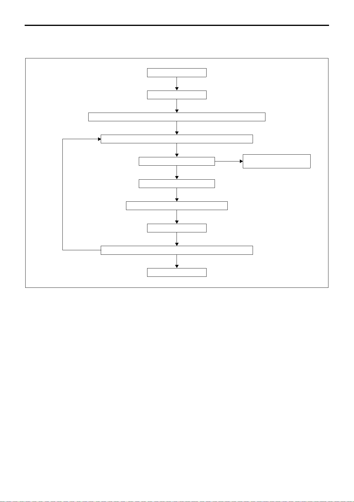
13-26
1. Diagnosis Procedure
• Perform the inspection in accordance with the following flowchart.
Vehicle in service shop
Read all (past and present) diagnosis codes by Multi-Use Tester. (See Gr00.)
Warning lamp lit
Was able to identify the fault?
Response to transient fault
(See Gr00.)
Perform inspection based on diagnosis codes. (See later section.)
Rectify or replace with new parts.
Clear stored diagnosis code. (See Gr00.)
Read diagnosis code(s) by Multi-Use Tester. (See Gr00.)
Code issued
End of inspection
Tes t d r i v e
NO
YES
No code issued
TROUBLESHOOTING <DIAGNOSIS USING Multi-Use Tester>

13
13-27
2. Diagnostic Precautions
• Before measuring voltage, check the battery for charged condition and specific gravity. If system inspection is per-
formed with the battery uncharged or reduced in specific gravity, accurate measurements cannot be achieved.
• Before disconnecting battery cables, harnesses and connectors, set the starter switch to LOCK or OFF, then allow
at least 20 seconds.
• To avoid having electrical parts damaged, set the starter switch and lighting switch to LOCK or OFF before recon-
necting battery cables, harnesses and connectors.
• When performing measurement with the tester, handle the test bar carefully so that it does not damage internal
circuit and other electrical parts of the electronic control unit to result in a short-circuit failure between terminals in
connector or between connector and car body.
• Resistance is affected by temperature. Determine the necessity of resistance measurement following given tem-
perature specification as a guide. Otherwise, use normal temperature (10 to 35°C) as the measuring condition.
• To start the engine, be sure to connect the connector of the MPROP (rail pressure control valve) to the engine
harness. If the engine is started without connecting the MPROP connector, the engine electronic control unit can-
not control the supply pump and the fault of the engine may result.

13-28
3. Inspections Based on Diagnosis Codes
3.1 Diagnosis code list
• Diagnosis codes shown by the Multi-Use Tester and those indicated by warning lamp display are different.
• The Multi-Use Tester is capable of showing more detailed diagnosis codes.
Code Message
Warning lamp indication
Remarks
Flashes Red Orange
P0107 Atmospheric Pressure Sensor 19 – O
P0108 Atmospheric Pressure Sensor 19 – O
P0112 INT Air Temp SNSR (Low) 44 – O
P0113 INT Air Temp SNSR (High) 44 – O
P0117 Water Temp SNSR (Low) 21 – O
P0118 Water Temp SNSR (High) 21 – O
P0121 Accel Pedal Check (Plausibility) 58 – O
P0122 Accel Pedal Sensor 1 24 – O
P0123 Accel Pedal Sensor 1 24 – O
P0182 Fuel Temp Sensor (inlet) Low 41 – O
P0183 Fuel Temp Sensor (inlet) High 41 – O
P0192 CRS Pressure SNSR (Low) 11 – O
P0193 CRS Pressure SNSR (High) 11 – O
P0200 Injector Circuit 1 82 – O
P0201 Injector M/V-Cylinder 1 (Load) 37 – O
P0202 Injector M/V-Cylinder 2 (Load) 38 – O
P0203 Injector M/V-Cylinder 3 (Load) 39 – O
P0204 Injector M/V-Cylinder 4 (Load) 8 – O
P0205 Injector M/V-Cylinder 5 (Load) 46 – O
P0206 Injector M/V-Cylinder 6 (Load) 47 – O
P0219 Engine Overrunning 7 O –
P0222 Accel Pedal Sensor 2 16 – O
P0223 Accel Pedal Sensor 2 16 – O
P0227 PTO Accel Sensor 61 – O
P0228 PTO Accel Sensor 61 – O
P0234 Over Boost 54 – O Gr15
P0237 Boost Press SNSR (Low) 32 – O
P0238 Boost Press SNSR (High) 32 – O
P0251 Common Rail Pressure Defect 36 – O
P0253 Common Rail Pressure Defect 22 O –
P0254 Common Rail Pressure Defect 23 O O
P0335 Engine Revolution SNSR 15 – O
P0340 Camshaft Position SNSR 12 – O
P0500 Vehicle Speed Sensor 25 – O
P0506 Idle Volume 31 – –
P0507 Idle Volume 31 – –
P0510 Accel SW 65 – –
P0560 M/V Supply Voltage 79 – O
P0600 CAN Communication – O –
P0605 ECU System (Hardware) 33 O O
P0615 Starter Safety Relay (Over Load) 48 – O Gr54
P0616 Starter Safety Relay (Low) 48 – O Gr54
TROUBLESHOOTING <DIAGNOSIS USING Multi-Use Tester>
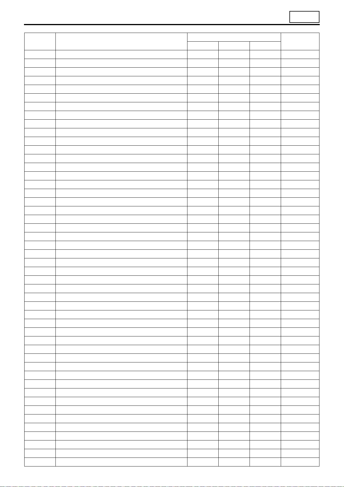
13
13-29
P0617 Starter Safety Relay (High) 48 – O Gr54
P1130 VGT 1 51 – O Gr15
P1132 VGT 1 51 – O Gr15
P1133 VGT 1 51 – O Gr15
P1135 VGT 2 52 – O Gr15
P1137 VGT 2 52 – O Gr15
P1138 VGT 2 52 – O Gr15
P1140 VGT 3 53 – O Gr15
P1142 VGT 3 53 – O Gr15
P1143 VGT 3 53 – O Gr15
P1171 Q Adjustment Resistor (Low) 34 – O
P1172 Q Adjustment Resistor (High) 34 – O
P1176 PTO Adjustment Resistor (Low) 62 – O
P1177 PTO Adjustment Resistor (High) 62 – O
P1200 Injector Circuit 2 82 – O
P1236 Turbine Revolution SNSR (Low) 57 – O Gr15
P1237 Turbine Revolution SNSR (High) 57 – O Gr15
P1238 Turbine Overrunning 59 – O Gr15
P1251 Common Rail Pressure M/V 1 63 – O
P1253 Common Rail Pressure M/V 2 63 – O
P1254 PRV Opening 36 – O
P1255 Common Rail Pressure M/V 1 63 – O
P1256 Common Rail Pressure M/V 1 63 – O
P1258 Common Rail Pressure M/V 2 63 – O
P1259 Common Rail Pressure M/V 2 63 – O
P125A Rail Pressure M/V 1 (Over Load) 63 O –
P125B Rail Pressure M/V 1 (Long Short) 63 O –
P125C Rail Pressure M/V 2 (Over Load) 63 O –
P125D Rail Pressure M/V 2 (Long Short) 63 O –
P1267 EGR 1 67 – O Gr17
P1268 EGR 1 67 – O Gr17
P1272 EGR 2 68 – O Gr17
P1273 EGR 2 68 – O Gr17
P1277 EGR 3 69 – O Gr17
P1278 EGR 3 69 – O Gr17
P1335 Revolution & Position Sensor 14 O –
P1460 Auxiliary Brake M/V 1 93 – O
P1462 Auxiliary Brake M/V 1 93 – O
P1463 Auxiliary Brake M/V 1 93 – O
P1562 Sensor Supply Voltage 1 81 – –
P1563 Sensor Supply Voltage 1 81 – –
P1567 Sensor Supply Voltage 2 81 – –
P1568 Sensor Supply Voltage 2 81 – –
P1572 Sensor Supply Voltage 3 81 – O
P1573 Sensor Supply Voltage 3 81 – O
P1605 ECU System (EEPROM) 33 – O
P1606 ECU System (Software) 33 O –
P1625 EDU Relay 84 – O Gr17
Code Message
Warning lamp indication
Remarks
Flashes Red Orange
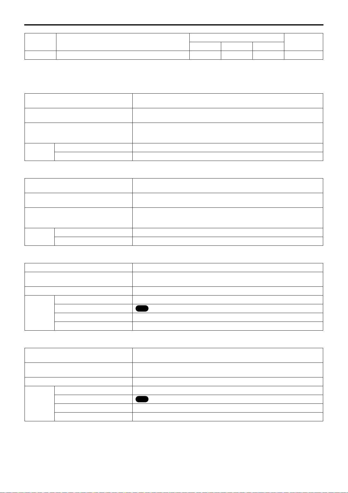
13-30
3.2 Diagnosis code generation conditions and inspection items
P0107: Atmospheric Pressure Sensor (warning lamp flashes: 19)
P0108: Atmospheric Pressure Sensor (warning lamp flashes: 19)
P0112: INT Air Temp SNSR (Low) (warning lamp flashes: 44)
P0113: INT Air Temp SNSR (High) (warning lamp flashes: 44)
P1630 CAN (EGR 1) 95 – O Gr17
Generation condition
Atmospheric pressure sensor (incorporated into engine electronic control unit)
voltage remains less than 2 V for 3 seconds.
Recoverability
System recovers when atmospheric pressure sensor (incorporated into engine
electronic control unit) remains 2 V or more for 1 second.
Control effected by electronic control unit
• Control is effected using backup value of 101.3 kPa {1.03 kgf/cm
2
}.
(Exhaust emissions worsen.)
• Exhaust gas recirculation control is stopped.
Inspection
Service data 30: Atmospheric Pressure
Other Replace engine electronic control unit.
Generation condition
Atmospheric pressure sensor (incorporated into engine electronic control unit)
voltage remains higher than 4.7 V for 3 seconds.
Recoverability
System recovers when atmospheric pressure sensor (incorporated into engine
electronic control unit) voltage remains 4.7 V or less for 1 second.
Control effected by electronic control unit
• Control is effected using backup value of 101.3 kPa {1.03 kgf/cm
2
}.
(Exhaust emissions worsen.)
• Exhaust gas recirculation control is stopped.
Inspection
Service data 30: Atmospheric Pressure
Other Replace engine electronic control unit.
Generation condition Intake air temperature sensor 1 voltage remains less than 0.15 V for 3 seconds.
Recoverability
System recovers when intake air temperature sensor 1 voltage remains 0.15 V or
more for 1 second.
Control effected by electronic control unit Control is effected using backup value (25°C).
Inspection
Service data 2B: Intake Air Temperature
Electronic control unit connector : Intake air temperature sensor 1
Electrical equipment #305: Intake air temperature sensor 1
Electric circuit diagram Intake air temperature sensor 1 system
Generation condition
Intake air temperature sensor 1 voltage remains higher than 4.85 V for 3 sec-
onds.
Recoverability
System recovers when intake air temperature sensor 1 voltage remains 4.85 V or
less for 1 second.
Control effected by electronic control unit Control is effected using backup value (25°C).
Inspection
Service data 2B: Intake Air Temperature
Electronic control unit connector : Intake air temperature sensor 1
Electrical equipment #305: Intake air temperature sensor 1
Electric circuit diagram Intake air temperature sensor 1 system
Code Message
Warning lamp indication
Remarks
Flashes Red Orange
01
01
TROUBLESHOOTING <DIAGNOSIS USING Multi-Use Tester>
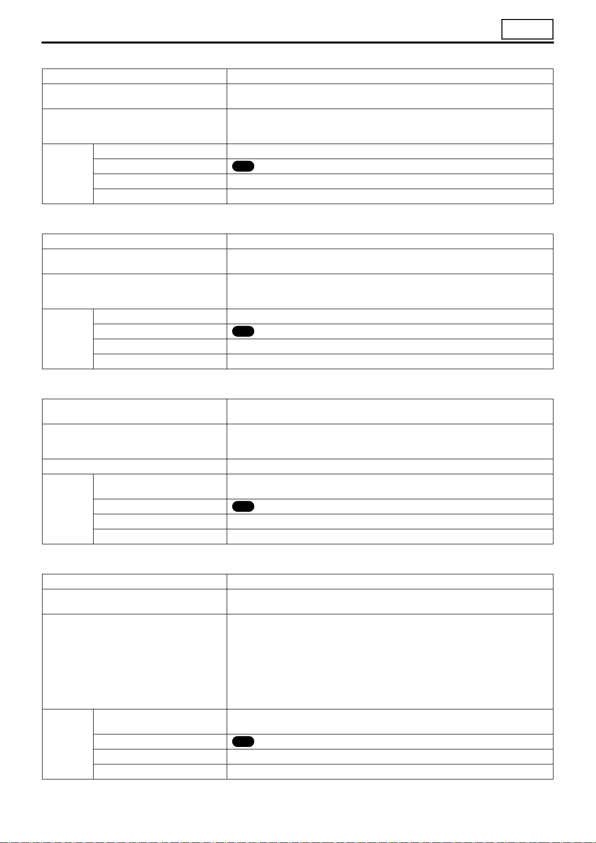
13
13-31
P0117: Water Temp SNSR (Low) (warning lamp flashes: 21)
P0118: Water Temp SNSR (High) (warning lamp flashes: 21)
P0121: Accel Pedal Check (Plausibility) (warning lamp flashes: 58)
P0122: Accel Pedal Sensor 1 (warning lamp flashes: 24)
Generation condition Water temperature sensor voltage remains less than 0.2 V for 3 seconds.
Recoverability
System recovers when water temperature sensor voltage remains 0.2 V or more
for 1 second.
Control effected by electronic control unit
• Control is effected using backup value (at engine startup: –20°C; when engine
is running: 80°C).
• Exhaust gas recirculation control is stopped.
Inspection
Service data 2E: Water Temperature
Electronic control unit connector : Water temperature sensor
Electrical equipment #262: Water temperature sensor
Electric circuit diagram Water temperature sensor system
Generation condition Water temperature sensor voltage remains higher than 4.85 V for 3 seconds.
Recoverability
System recovers when water temperature sensor voltage remains 4.85 V or less
for 1 second.
Control effected by electronic control unit
• Control is effected using backup value (at engine startup: –20°C; when engine
is running: 80°C).
• Exhaust gas recirculation control is stopped.
Inspection
Service data 2E: Water Temperature
Electronic control unit connector : Water temperature sensor
Electrical equipment #262: Water temperature sensor
Electric circuit diagram Water temperature sensor system
Generation condition
The difference in output voltage between accelerator pedal position sensors 1
and 2 remains 70% or more for 6 seconds when the sensors are normal.
Recoverability
System recovers if difference in output voltage between accelerator pedal posi-
tion sensors 1 and 2 remains less than 70% for 3 seconds when the sensors are
normal.
Control effected by electronic control unit – (Low output)
Inspection
Service data
22: Accel Pedal Position (unfiltered), 23: Accel Pedal Position (filtered)
24: Accel Pedal Sensor Voltage 1, 25: Accel Pedal Sensor Voltage 2
Electronic control unit connector : Accelerator pedal position sensor
Electrical equipment #324: Accelerator pedal position sensor
Electric circuit diagram Accelerator pedal position sensor system
Generation condition Accelerator pedal position sensor 1 voltage remains less than 0.5 V for 1 second.
Recoverability
System recovers when accelerator pedal position sensor 1 voltage remains 0.5 V
or more for 1 second.
Control effected by electronic control unit
• If accelerator pedal position sensor 1 alone is faulty
Control is effected using accelerator pedal position sensor 2.
• If both accelerator pedal position sensors 1 and 2 are faulty
• Exhaust gas recirculation control is stopped.
• Auto cruise control is stopped.
• Turbocharger control is stopped.
• Control is effected using backup value (when accelerator pedal switch is
ON: accelerator pedal is not pressed (0%); when the switch is OFF: the
pedal is pressed 30%).
Inspection
Service data
22: Accel Pedal Position (unfiltered), 23: Accel Pedal Position (filtered)
24: Accel Pedal Sensor Voltage 1
Electronic control unit connector : Accelerator pedal position sensor
Electrical equipment #324: Accelerator pedal position sensor
Electric circuit diagram Accelerator pedal position sensor 1 system
02
02
03
03
13-32
P0123: Accel Pedal Sensor 1 (warning lamp flashes: 24)
P0182: Fuel Temp Sensor (inlet) Low (warning lamp flashes: 41)
P0183: Fuel Temp Sensor (inlet) High (warning lamp flashes: 41)
P0192: CRS Pressure SNSR (Low) (warning lamp flashes: 11)
Generation condition
Accelerator pedal position sensor 1 voltage remains higher than 4.5 V for 1 sec-
ond.
Recoverability
System recovers when accelerator pedal position sensor 1 voltage remains 4.5 V
or less for 1 second.
Control effected by electronic control unit
• If accelerator pedal position sensor 1 alone is faulty
Control is effected using accelerator pedal position sensor 2.
• If both accelerator pedal position sensors 1 and 2 are faulty
• Exhaust gas recirculation control is stopped.
• Auto cruise control is stopped.
• Turbocharger control is stopped.
• Control is effected using backup value (when accelerator pedal switch is
ON: accelerator pedal is not pressed (0%); when the switch is OFF: the
pedal is pressed 30%).
Inspection
Service data
22: Accel Pedal Position (unfiltered), 23: Accel Pedal Position (filtered)
24: Accel Pedal Sensor Voltage 1
Electronic control unit connector : Accelerator pedal position sensor
Electrical equipment #324: Accelerator pedal position sensor
Electric circuit diagram Accelerator pedal position sensor 1 system
Generation condition Fuel temperature sensor voltage remains less than 0.15 V for 3 seconds.
Recoverability
System recovers when fuel temperature sensor voltage remains 0.15 V or more
for 1 second.
Control effected by electronic control unit Control is effected using backup value (40°C).
Inspection
Service data 2F: Fuel Temperature (Inlet)
Electronic control unit connector : Fuel temperature sensor
Electrical equipment #323: Fuel temperature sensor
Electric circuit diagram Fuel temperature sensor system
Generation condition Fuel temperature sensor voltage remains higher than 4.8 V for 3 seconds.
Recoverability
System recovers when fuel temperature sensor voltage remains 4.8 V or less for
1 second.
Control effected by electronic control unit Control is effected using backup value (40°C).
Inspection
Service data 2F: Fuel Temperature (Inlet)
Electronic control unit connector : Fuel temperature sensor
Electrical equipment #323: Fuel temperature sensor
Electric circuit diagram Fuel temperature sensor system
Generation condition Common rail pressure sensor voltage remains less than 0.2 V for 0.25 second.
Recoverability
System recovers (power is re-supplied to electronic control unit) if signal becomes
normal when starter switch is turned OFF (2 minutes or more) → ON.
Control effected by electronic control unit
• Common rail pressure open loop control is effected.
(Output is reduced, and exhaust emissions worsen.)
• Exhaust gas recirculation control is stopped.
• Auto cruise control is stopped.
• Actuator tests “B9: Fuel Leak Check, BB to C0: Injector Test, BA: VGT Test”
are stopped.
Inspection
Service data 0C: Difference Common Rail Pressure
Electrical equipment #319: Common rail pressure sensor
Electric circuit diagram Common rail pressure sensor system
03
04
04
TROUBLESHOOTING <DIAGNOSIS USING Multi-Use Tester>
13
13-33
P0193: CRS Pressure SNSR (High) (warning lamp flashes: 11)
P0200: Injector Circuit 1 (warning lamp flashes: 82)
P0201: Injector M/V-Cylinder 1 (Load) (warning lamp flashes: 37)
Generation condition Common rail pressure sensor voltage remains higher than 4.8 V for 0.25 second.
Recoverability
System recovers (power is re-supplied to electronic control unit) if signal becomes
normal when starter switch is turned OFF (2 minutes or more) → ON.
Control effected by electronic control unit
• Common rail pressure open loop control is effected.
(Output is reduced, and exhaust emissions worsen.)
• Exhaust gas recirculation control is stopped.
• Auto cruise control is stopped.
• Actuator tests “B9: Fuel Leak Check, BB to C0: Injector Test, BA: VGT Test”
are stopped.
Inspection
Service data 0C: Difference Common Rail Pressure
Electrical equipment #319: Common rail pressure sensor
Electric circuit diagram Common rail pressure sensor system
Generation condition
Injector circuit (No. 1, 2 or 3 cylinder) is short-circuited, open-circuited, or over-
loaded.
Recoverability
System recovers (power is re-supplied to electronic control unit) if signal be-
comes normal when starter switch is turned OFF (2 minutes or more) → ON.
Control effected by electronic control unit
• Injector magnetic valve (No. 1, 2 or 3 cylinder) control is stopped. (Output is
reduced due to three-cylinder operation, and exhaust emissions worsen.)
• Exhaust gas recirculation control is stopped.
• Auto cruise control is stopped.
• Turbocharger control is stopped.
• Actuator tests “B9: Fuel Leak Check, BB to C0: Injector Test, BA: VGT Test”
are stopped.
Inspection
Actuator test BB: Injector Test 1, BC: Injector Test 2, BD: Injector Test 3,
Electronic control unit connector : Injector magnetic valve
Electrical equipment #582: Injector magnetic valve
Electric circuit diagram Injector magnetic valve (No. 1, 2 or 3 cylinder) system
Generation condition
Injector magnetic valve (No. 1 cylinder) is short-circuited, open-circuited or over-
loaded.
Recoverability
• When short-circuited or overloaded
• System recovers (power is re-supplied to electronic control unit) if signal
becomes normal when starter switch is turned OFF (2 minutes or more) →
ON.
• When open-circuited
• System recovers if signal becomes normal with starter switch in ON posi-
tion.
Control effected by electronic control unit
• Exhaust gas recirculation control is stopped.
• Injector magnetic valves (No. 1, 2 and 3 cylinder) are stopped.
(Output is reduced, and exhaust emissions worsen.)
• Auto cruise control is stopped.
• Actuator test “BA: VGT Test” is stopped.
Inspection
Actuator test BB: Injector Test 1
Electronic control unit connector : Injector magnetic valve
Electrical equipment #582: Injector magnetic valve
Electric circuit diagram Injector magnetic valve (No. 1 cylinder) system
05
05

13-34
P0202: Injector M/V-Cylinder 2 (Load) (warning lamp flashes: 38)
P0203: Injector M/V-Cylinder 3 (Load) (warning lamp flashes: 39)
P0204: Injector M/V-Cylinder 4 (Load) (warning lamp flashes: 08)
Generation condition
Injector magnetic valve (No. 5 cylinder) is short-circuited, open-circuited or over-
loaded.
Recoverability
• When short-circuited or overloaded
• System recovers (power is re-supplied to electronic control unit) if signal
becomes normal when starter switch is turned OFF (2 minutes or more) →
ON.
• When open-circuited
• System recovers if signal becomes normal with starter switch in ON posi-
tion.
Control effected by electronic control unit
• Exhaust gas recirculation control is stopped.
• Injector magnetic valves (No. 4, 5 and 6 cylinder) are stopped.
(Output is reduced, and exhaust emissions worsen.)
• Auto cruise control is stopped.
• Actuator test “BA: VGT Test” is stopped.
Inspection
Actuator test BF: Injector Test 5
Electronic control unit connector : Injector magnetic valve
Electrical equipment #582: Injector magnetic valve
Electric circuit diagram Injector magnetic valve (No. 5 cylinder) system
Generation condition
Injector magnetic valve (No. 3 cylinder) is short-circuited, open-circuited or over-
loaded.
Recoverability
• When short-circuited or overloaded
• System recovers (power is re-supplied to electronic control unit) if signal
becomes normal when starter switch is turned OFF (2 minutes or more) →
ON.
• When open-circuited
• System recovers if signal becomes normal with starter switch in ON posi-
tion.
Control effected by electronic control unit
• Exhaust gas recirculation control is stopped.
• Injector magnetic valves (No. 1, 2 and 3 cylinder) are stopped.
(Output is reduced, and exhaust emissions worsen.)
• Auto cruise control is stopped.
• Actuator test “BA: VGT Test” is stopped.
Inspection
Actuator test BD: Injector Test 3
Electronic control unit connector : Injector magnetic valve
Electrical equipment #582: Injector magnetic valve
Electric circuit diagram Injector magnetic valve (No. 3 cylinder) system
Generation condition
Injector magnetic valve (No. 6 cylinder) is short-circuited, open-circuited or over-
loaded.
Recoverability
• When short-circuited or overloaded
• System recovers (power is re-supplied to electronic control unit) if signal
becomes normal when starter switch is turned OFF (2 minutes or more) →
ON.
• When open-circuited
• System recovers if signal becomes normal with starter switch in ON posi-
tion.
Control effected by electronic control unit
• Exhaust gas recirculation control is stopped.
• Injector magnetic valves (No. 4, 5 and 6 cylinder) are stopped.
(Output is reduced, and exhaust emissions worsen.)
• Auto cruise control is stopped.
• Actuator test “BA: VGT Test” is stopped.
Inspection
Actuator test C0: Injector Test 6
Electronic control unit connector : Injector magnetic valve
Electrical equipment #582: Injector magnetic valve
Electric circuit diagram Injector magnetic valve (No. 6 cylinder) system
05
05
05
TROUBLESHOOTING <DIAGNOSIS USING Multi-Use Tester>
13
13-35
P0205: Injector M/V-Cylinder 5 (Load) (warning lamp flashes: 46)
P0206: Injector M/V-Cylinder 6 (Load) (warning lamp flashes: 47)
P0219: Engine Overrunning (warning lamp flashes: 07)
Generation condition
Injector magnetic valve (No. 2 cylinder) is short-circuited, open-circuited or over-
loaded.
Recoverability
• When short-circuited or overloaded
• System recovers (power is re-supplied to electronic control unit) if signal
becomes normal when starter switch is turned OFF (2 minutes or more) →
ON.
• When open-circuited
• System recovers if signal becomes normal with starter switch in ON posi-
tion.
Control effected by electronic control unit
• Exhaust gas recirculation control is stopped.
• Injector magnetic valves (No. 1, 2 and 3 cylinder) are stopped.
(Output is reduced, and exhaust emissions worsen.)
• Auto cruise control is stopped.
• Actuator test “BA: VGT Test” is stopped.
Inspection
Actuator test BC: Injector Test 2
Electronic control unit connector : Injector magnetic valve
Electrical equipment #582: Injector magnetic valve
Electric circuit diagram Injector magnetic valve (No. 2 cylinder) system
Generation condition
Injector magnetic valve (No. 4 cylinder) is short-circuited, open-circuited or over-
loaded.
Recoverability
• When short-circuited or overloaded
• System recovers (power is re-supplied to electronic control unit) if signal
becomes normal when starter switch is turned OFF (2 minutes or more) →
ON.
• When open-circuited
• System recovers if signal becomes normal with starter switch in ON posi-
tion.
Control effected by electronic control unit
• Exhaust gas recirculation control is stopped.
• Injector magnetic valves (No. 4, 5 and 6 cylinder) are stopped.
(Output is reduced, and exhaust emissions worsen.)
• Auto cruise control is stopped.
• Actuator test “BA: VGT Test” is stopped.
Inspection
Actuator test BE: Injector Test 4
Electronic control unit connector : Injector magnetic valve
Electrical equipment #582: Injector magnetic valve
Electric circuit diagram Injector magnetic valve (No. 4 cylinder) system
Generation condition Engine speed is 2900 rpm or higher.
Recoverability System recovers if engine speed is 2500 rpm or less.
Control effected by electronic control unit
• No feed from MPROP (rail pressure control valve)
• Exhaust gas recirculation control
• Auto cruise control is stopped.
• Turbocharger control is stopped.
Inspection Other
• Check for occurrences of diagnosis code "P0335: Engine Revolution SNSR".
• If the diagnosis code is redisplayed with the pointer of the tachometer not
reaching the red zone, replace the engine electronic control unit.
05
05

13-36
P0222: Accel Pedal Sensor 2 (warning lamp flashes: 16)
P0223: Accel Pedal Sensor 2 (warning lamp flashes: 16)
P0227: PTO Accel Pedal Sensor (warning lamp flashes: 61)
Generation condition Accelerator pedal position sensor 2 voltage remains less than 0.5 V for 1 second.
Recoverability
System recovers when accelerator pedal position sensor 2 voltage remains 0.5 V
or more for 1 second.
Control effected by electronic control unit
• If accelerator pedal position sensor 2 alone is faulty
Control is effected using accelerator pedal position sensor 1.
• If both accelerator pedal position sensors 1 and 2 are faulty
• Exhaust gas recirculation control is stopped.
• Auto cruise control is stopped.
• Turbocharger control is stopped.
• Control is effected using backup value (when accelerator pedal switch is
ON: accelerator pedal is not pressed (0%); when the switch is OFF: the
pedal is pressed 30%).
Inspection
Service data
22: Accel Pedal Position (unfiltered), 23: Accel Pedal Position (filtered)
25: Accel Pedal Sensor Voltage 2
Electronic control unit connector : Accelerator pedal position sensor
Electrical equipment #324: Accelerator pedal position sensor
Electric circuit diagram Accelerator pedal position sensor 2 system
Generation condition
Accelerator pedal position sensor 2 voltage remains higher than 4.5 V for 1 sec-
ond.
Recoverability
System recovers when accelerator pedal position sensor 2 voltage remains 4.5 V
or less for 1 second.
Control effected by electronic control unit
• If accelerator pedal position sensor 2 alone is faulty
Control is effected using accelerator pedal position sensor 1.
• If both accelerator pedal position sensors 1 and 2 are faulty
• Exhaust gas recirculation control is stopped.
• Auto cruise control is stopped.
• Turbocharger control is stopped.
• Control is effected using backup value (when accelerator pedal switch is
ON: accelerator pedal is not pressed (0%); when the switch is OFF: the
pedal is pressed 30%).
Inspection
Service data
22: Accel Pedal Position (unfiltered), 23: Accel Pedal Position (filtered)
25: Accel Pedal Sensor Voltage 2
Electronic control unit connector : Accelerator pedal position sensor
Electrical equipment #324: Accelerator pedal position sensor
Electric circuit diagram Accelerator pedal position sensor 2 system
Generation condition
Voltage of power take-off load sensor remains less than 0.5 V for 1 second when
governor control switch is ON.
Recoverability
System recovers when voltage of power take-off load sensor remains 0.5 V or
more for 1 second when governor control switch is ON.
Control effected by electronic control unit
• When governor control switch is ON
• Engine warning lamp (orange) display
• Control is effected using backup value (output: 0%).
Inspection
Service data 34: PTO Accel Position, 35: PTO Accel Sensor Voltage
Electronic control unit connector : Power take-off load sensor
Electrical equipment #317: Power take-off load sensor
Electric circuit diagram Power take-off load sensor system
03
03
06
TROUBLESHOOTING <DIAGNOSIS USING Multi-Use Tester>
13
13-37
P0228: PTO Accel Sensor (warning lamp flashes: 61)
P0237: Boost Press SNSR (Low) (warning lamp flashes: 32)
P0238: Boost Press SNSR (High) (warning lamp flashes: 32)
Generation condition
Voltage of power take-off load sensor remains higher than 3.5 V for 1 second
when governor control switch is ON.
Recoverability
System recovers when voltage of power take-off load sensor remains 3.5 V or
less for 1 second when governor control switch is ON.
Control effected by electronic control unit
• When governor control switch is ON
• Engine warning lamp (orange) display
• Control is effected using backup value (output: 0%).
Inspection
Service data 34: PTO Accel Position, 35: PTO Accel Sensor Voltage
Electronic control unit connector : Power take-off load sensor
Electrical equipment #317: Power take-off load sensor
Electric circuit diagram Power take-off load sensor system
Generation condition Boost pressure sensor voltage remains less than 0.3 V for 3 seconds.
Recoverability
System recovers when boost pressure sensor voltage remains 0.3 V or more for
1 second.
Control effected by electronic control unit
• Control is effected using backup value of 101.3 kPa {1.03 kgf/cm
2
}. (Output is
reduced, and fuel economy worsens.)
• Actuator test “BA: VGT Test” is stopped.
Inspection
Service data 26: Boost Pressure
Electrical equipment #318: Boost pressure sensor
Electric circuit diagram Boost pressure sensor system
Generation condition Boost pressure sensor voltage remains higher than 4.7 V for 3 seconds.
Recoverability
System recovers when boost pressure sensor voltage remains 4.7 V or less for 1
second.
Control effected by electronic control unit
• Control is effected using backup value of 101.3 kPa {1.03 kgf/cm
2
}. (Output is
reduced, and fuel economy worsens.)
• Actuator test “BA: VGT Test” is stopped.
Inspection
Service data 26: Boost Pressure
Electrical equipment #318: Boost pressure sensor
Electric circuit diagram Boost pressure sensor system
06
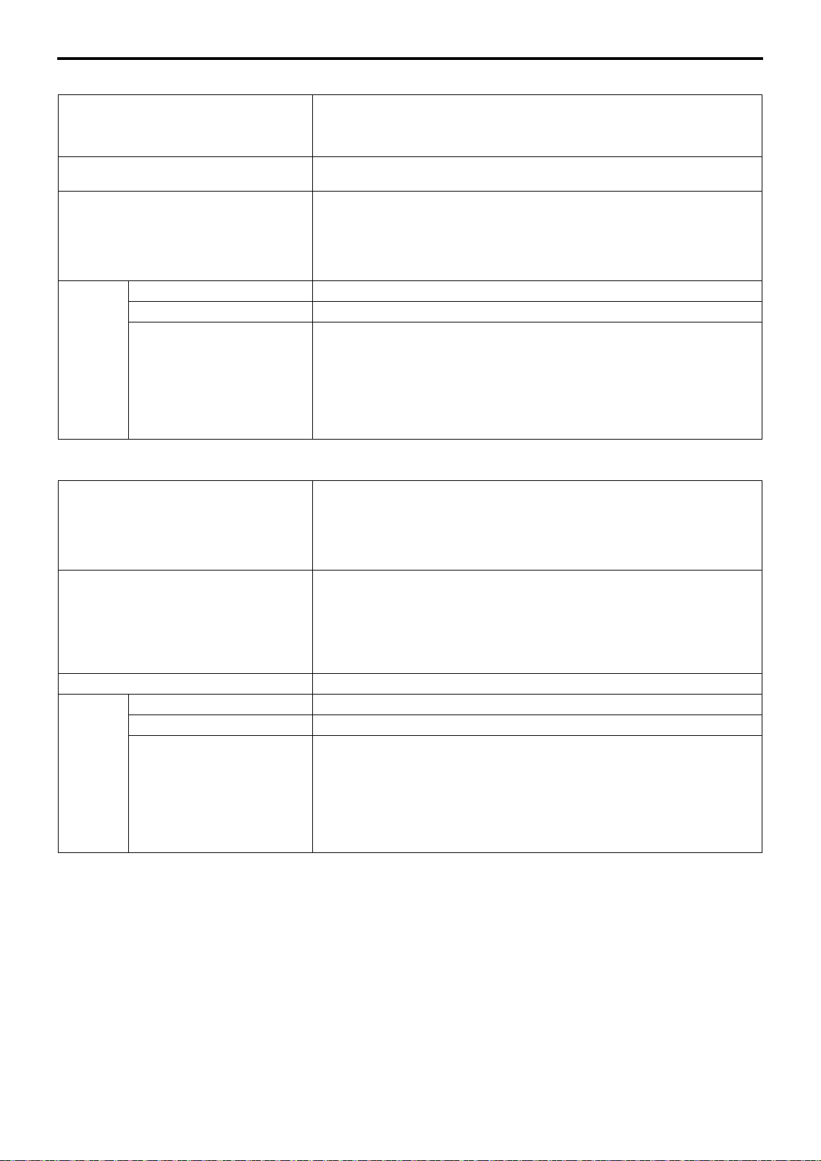
13-38
P0251: Common Rail Pressure Defect (warning lamp flashes: 36)
P0253: Common Rail Pressure Defect (warning lamp flashes: 22)
Generation condition
Diagnosis code is generated under either of the following conditions.
(1) MPROP (rail pressure control valve) power supply remains low for 1 second.
(2) The difference between target common rail pressure and actual common rail
pressure remains 30% or more for 10 seconds.
Recoverability
System recovers (power is re-supplied to electronic control unit) if signal becomes
normal when starter switch is turned OFF (2 minutes or more) → ON.
Control effected by electronic control unit
• In the case of above problem (1)
• No specific control is effected.
• In the case of above problem (2)
• Injection quantity is limited. (Output is reduced.)
• Exhaust gas recirculation control is stopped.
• Auto cruise control is stopped.
Inspection
Service data 0C: Difference Common Rail Pressure
Actuator test B9: Fuel Leak Check
Other
• Air-bleeding of fuel system (See “ON-VEHICLE INSPECTION AND ADJUST-
MENT”.)
• Inspection of fuel piping (See “COMMON RAIL”.)
• Fuel filter (See “FUEL FILTER”.)
• Gauze filter (See “ON-VEHICLE INSPECTION AND ADJUSTMENT”.)
• Supply pump (Have work performed by Bosch.)
• Pressure limiting valve (Have work performed by Bosch.)
• Injectors (Have work performed by Bosch.)
Generation condition
Diagnosis code is generated under either of the following conditions.
(1) Common rail pressure sensor voltage remains less than 0.74 V for 30 sec-
onds.
(2) The difference between target common rail pressure and actual common rail
pressure is 30% or more, and MPROP (rail pressure control valve) discharge
rate remains above the specified value for 60 seconds.
Recoverability
• In the case of above problem (1)
• System recovers when common rail pressure sensor voltage remains 0.74
V or more for 5 seconds.
• In the case of above problem (2)
• System recovers when the difference between target rail pressure and ac-
tual rail pressure is 30% or less, or MPROP (rail pressure control valve)
discharge rate remains less than the specified value for 5 seconds.
Control effected by electronic control unit Engine is stopped.
Inspection
Service data C0: Difference Common Rail Pressure
Actuator test B9: Fuel Leak Check
Other
• Air-bleeding of fuel system (See “ON-VEHICLE INSPECTION AND ADJUST-
MENT”.)
• Inspection of fuel piping (See “COMMON RAIL”.)
• Fuel filter (See “FUEL FILTER”.)
• Gauze filter (See “ON-VEHICLE INSPECTION AND ADJUSTMENT”.)
• Supply pump (Have work performed by Bosch.)
• Pressure limiting valve (Have work performed by Bosch.)
• Injectors (Have work performed by Bosch.)
TROUBLESHOOTING <DIAGNOSIS USING Multi-Use Tester>
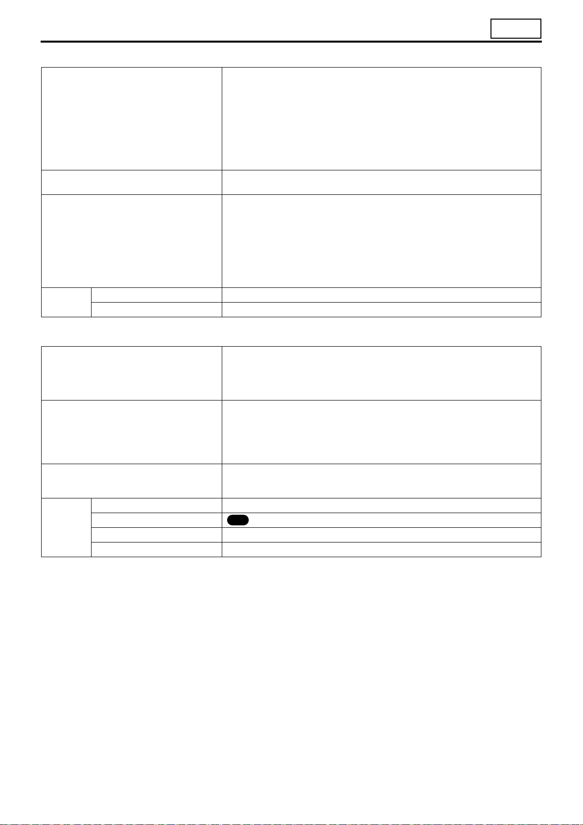
13
13-39
P0254: Common Rail Pressure Defect (warning lamp flashes: 23)
P0335: Engine Revolution SNSR (warning lamp flashes: 15)
Generation condition
Diagnosis code is generated under either of the following conditions.
(1) Common rail pressure sensor voltage remains 4.4 V or more for 10 seconds
when common rail pressure is controlled without feedback value.
(2) When above problem (1) is not occurred, common rail pressure sensor volt-
age remains 2.96 V or more for 10 seconds when common rail pressure is
controlled without feedback value.
(3) Common rail pressure sensor voltage remains 4.4 V or more for 5 seconds.
(4) The difference between target common rail pressure and actual common rail
pressure is 30% or more, and MPROP (rail pressure control valve) discharge
rate remains above the specified value for 10 seconds.
Recoverability
System recovers (power is re-supplied to electronic control unit) if signal becomes
normal when starter switch is turned OFF (2 minutes or more) → ON.
Control effected by electronic control unit
• In the case of above problems (1) and (2)
• Engine warning lamp (red) display
• Engine is stopped.
• In the case of above problems (3) and (4)
• Engine warning lamp (orange) display
• Injection quantity is limited. (Output is reduced, and exhaust emissions
worsen.)
• Exhaust gas recirculation control is stopped.
• Auto cruise control is stopped.
Inspection
Service data C0: Difference Common Rail Pressure
Other Supply pump (Have work performed by Bosch.)
Generation condition
Diagnosis code is generated under either of the following conditions.
(1) Signals from engine speed sensor are not input while signals from cylinder
recognition sensor are recognized.
(2) Engine speed recognized by engine speed sensor is higher than 6000 rpm
when engine speed is higher than 450 rpm.
Recoverability
• In the case of above problem (1)
• System recovers if signals from engine speed sensor are input while sig-
nals from cylinder recognition sensor are recognized.
• In the case of above problem (2)
• System recovers if engine speed recognized by engine speed sensor is
6000 rpm or less when engine speed is higher than 450 rpm.
Control effected by electronic control unit
• Control is effected using cylinder recognition sensor.
(Output decreases owing to reduced control accuracy.)
• Auto cruise control is stopped.
Inspection
Service data 01: Engine Revolution
Electronic control unit connector : Engine speed sensor
Electrical equipment #263: Engine speed sensor
Electric circuit diagram Engine speed sensor system
07
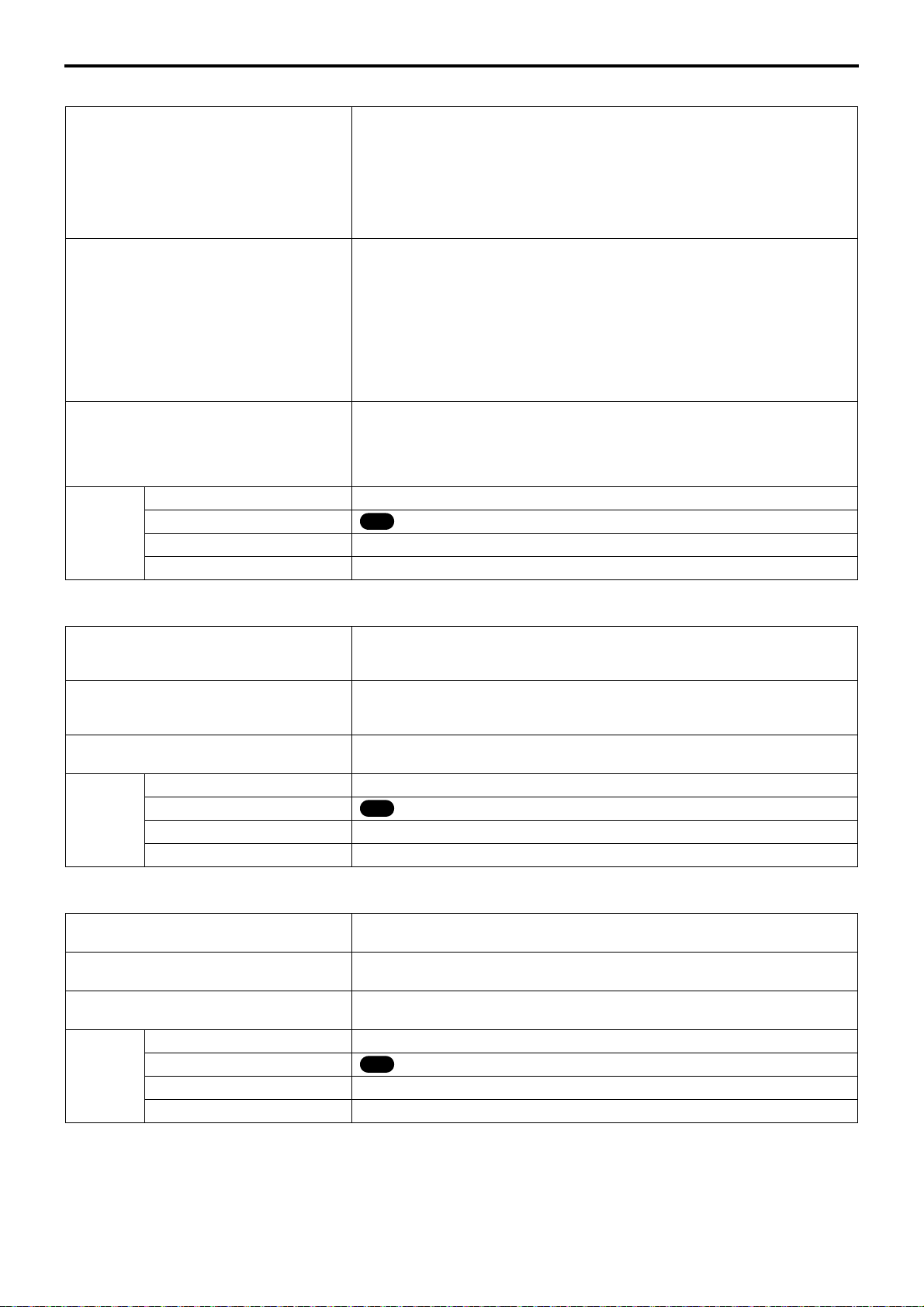
13-40
P0340: Camshaft Position SNSR (warning lamp flashes: 12)
P0500: Vehicle Speed Sensor (warning lamp flashes: 25)
P0506: Idle Volume (warning lamp flashes: 31)
Generation condition
Diagnosis code is generated under either of the following conditions.
(1) Phase difference between cylinder recognition sensor and engine speed sen-
sor deviates from the standard value when engine speed is 20 rpm or more.
(2) No signal from the cylinder recognition sensor during the 132-pulse inputs of
the engine speed sensor signal after recognition of the gap of the engine
speed sensor.
(3) Abnormal signal (timing) of cylinder recognition sensor signal during the 240-
pulse inputs of the engine speed sensor signal.
Recoverability
• In the case of above problem (1)
• System recovers when phase difference between cylinder recognition sen-
sor and engine speed sensor is within the standard value when engine
speed is 20 rpm or more.
• In the case of above problem (2)
• System recovers when signals from cylinder recognition sensor are input.
• In the case of above problem (3)
• System recovers when the signal (timing) of cylinder recognition sensor
signal during the 240-pulse inputs of the engine speed sensor signal be-
comes normal.
Control effected by electronic control unit
• In the case of above problem (1)
• Control is effected using engine speed sensor.
• In the case of above problems (2) and (3)
• Control is effected using engine speed sensor.
• Auto cruise control is stopped.
Inspection
Service data 01: Engine Revolution
Electronic control unit connector : Cylinder recognition sensor
Electrical equipment #320: Cylinder recognition sensor
Electric circuit diagram Cylinder recognition sensor system
Generation condition
Vehicle speed remains 2 km/h or less for 20 seconds when engine speed is 1000
rpm or more, clutch pedal is released and transmission neutral signal indicates
that transmission is in gear.
Recoverability
System recovers when vehicle speed remains 2 km/h or more for 3 seconds
when engine speed is 1000 rpm or more, clutch pedal is released and transmis-
sion neutral signal indicates that transmission is in gear.
Control effected by electronic control unit
• Auto cruise control is stopped.
• Vehicle speed limiting control is stopped. (Engine speed is also limited.)
Inspection
Service data 29: Vehicle Speed
Electronic control unit connector : Vehicle speed sensor
Electrical equipment #265: Vehicle speed sensor
Electric circuit diagram Vehicle speed sensor system
Generation condition
Idling speed adjustment potentiometer voltage remains less than 0.7 V for 3 sec-
onds.
Recoverability
System recovers when idling speed adjustment potentiometer voltage remains
0.7 V or more for 1 second.
Control effected by electronic control unit
• Control is effected with auto idle permanently selected.
• Actuator test “BA: VGT Test” is stopped.
Inspection
Service data 28: Idle Volume Voltage
Electronic control unit connector : Idling speed adjustment potentiometer
Electrical equipment #157: Idling speed adjustment potentiometer
Electric circuit diagram Idling speed adjustment potentiometer system
08
09
10
TROUBLESHOOTING <DIAGNOSIS USING Multi-Use Tester>
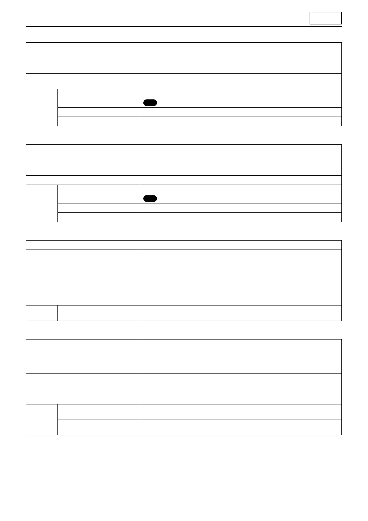
13
13-41
P0507: Idle Volume (warning lamp flashes: 31)
P0510: Accel SW (warning lamp flashes: 65)
P0560: M/V Supply Voltage (warning lamp flashes: 79)
P0600: CAN Communication (warning lamp flashes: –)
Generation condition
Idling speed adjustment potentiometer voltage remains higher than 4.6 V for 3
seconds.
Recoverability
System recovers when idling speed adjustment potentiometer voltage remains
4.6 V or less for 1 second.
Control effected by electronic control unit
• Control is effected with auto idle permanently selected.
• Actuator test “BA: VGT Test” is stopped.
Inspection
Service data 28: Idle Volume Voltage
Electronic control unit connector : Idling speed adjustment potentiometer
Electrical equipment #157: Idling speed adjustment potentiometer
Electric circuit diagram Idling speed adjustment potentiometer system
Generation condition
Accelerator pedal switch remains ON for 1 second when accelerator pedal posi-
tion is higher than 30%.
Recoverability
System recovers if accelerator pedal switch is turned OFF when accelerator ped-
al position is 30% or lower.
Control effected by electronic control unit No specific control is effected.
Inspection
Service data 73: Accel SW
Electronic control unit connector : Accelerator pedal switch
Electrical equipment #029: Accelerator pedal switch
Electric circuit diagram Accelerator pedal switch system
Generation condition Magnetic valve power supply remains low for 0.5 second.
Recoverability
System recovers (power is re-supplied to electronic control unit) if signal becomes
normal when starter switch is turned OFF (2 minutes or more) → ON.
Control effected by electronic control unit
• Turbocharger magnetic valve control is stopped.
• Safety relay control is stopped.
• Powertard magnetic valve control is stopped.
• Electronic drive unit relay control is stopped.
• Following controls are stopped by stopping electronic drive unit relay control.
• Exhaust gas recirculation control is stopped.
Inspection Other
Replace engine electronic control unit. (See “6. Registration or Change of the
Engine Electronic Control Unit Information”.)
Generation condition
Diagnosis code is generated under either of the following conditions.
• No controller area network signals from multi function vehicle control unit are
received for 1.8 seconds.
• Controller area network signal from MVCU indicating “vehicle speed limitation
device (SLD) is abnormal” is received.
Recoverability
System recovers (power is re-supplied to electronic control unit) if signal becomes
normal when starter switch is turned OFF (2 minutes or more) → ON.
Control effected by electronic control unit
• Engine speed is limited.
• Vehicle speed limiting control is stopped.
Inspection
Electric circuit diagram
Controller area network communication system between engine electronic con-
trol unit and multi function vehicle control unit
Other
Check the combination of engine electronic control unit and multi function vehicle
control unit
10
11
13-42
P0605: ECU System (Hardware) (warning lamp flashes: 33)
P1171: Q Adjustment Resistor (Low) (warning lamp flashes: 34)
P1172: Q Adjustment Resistor (High) (warning lamp flashes: 34)
P1176: PTO Adjustment Resistor (Low) (warning lamp flashes: 62)
Generation condition
Diagnosis code is generated under either of the following conditions.
(1) Power supply circuit or power supply in electronic control unit is abnormal.
(2) Devices (analog-digital converter, IC for driving injector or timer IC) in electron-
ic control unit or CPU gate array communication are abnormal.
Recoverability
• In the case of above problem (1)
• System recovers if power supply circuit or power supply in electronic con-
trol unit becomes normal.
• In the case of above problem (2)
• System recovers (power is re-supplied to electronic control unit) if signal
becomes normal when starter switch is turned OFF → ON.
Control effected by electronic control unit
• In the case of above problem (1)
• Engine warning lamp (orange) display
• In the case of above problem (2)
• Engine warning lamp (red) display
• Engine is stopped.
Inspection Other Replace the engine electronic control unit.
Generation condition
Fuel injection rate adjustment resistor voltage remains less than 0.2 V for 3 sec-
onds.
Recoverability
System recovers when fuel injection rate adjustment resistor voltage remains 0.2
V or more for 1 second.
Control effected by electronic control unit Control is effected using backup value (No. 1). (Output is slightly reduced.)
Inspection
Service data 33: Q Adjustment Resistor No.
Electronic control unit connector : Fuel injection rate adjustment resistor
Electrical equipment #828: Fuel injection rate adjustment resistor
Electric circuit diagram Fuel injection rate adjustment resistor system
Generation condition
Fuel injection rate adjustment resistor voltage remains higher than 4.8 V for 3
seconds.
Recoverability
System recovers when fuel injection rate adjustment resistor voltage remains 4.8
V or less for 1 second.
Control effected by electronic control unit Control is effected using backup value (No. 1). (Output is slightly reduced.)
Inspection
Service data 33: Q Adjustment Resistor No.
Electronic control unit connector : Fuel injection rate adjustment resistor
Electrical equipment #828: Fuel injection rate adjustment resistor
Electric circuit diagram Fuel injection rate adjustment resistor system
Generation condition
Power take-off resistor voltage remains less than 0.2 V for 3 seconds when gov-
ernor control switch is ON.
Recoverability
System recovers when power take-off resistor voltage remains 0.2 V or more for
1 second when governor control switch is ON.
Control effected by electronic control unit Control is effected using backup value (not resistor).
Inspection
Service data 36: PTO Adjustment Resistor No.
Electronic control unit connector : Power take-off resistor
Electrical equipment #828: Power take-off resistor
Electric circuit diagram Power take-off resistor system
12
12
13
TROUBLESHOOTING <DIAGNOSIS USING Multi-Use Tester>
13
13-43
P1177: PTO Adjustment Resistor (High) (warning lamp flashes: 62)
P1200: Injector Circuit 2 (warning lamp flashes: 82)
P1251: Common Rail Pressure M/V 1 (warning lamp flashes: 63)
P1253: Common Rail Pressure M/V 2 (warning lamp flashes: 63)
Generation condition
Power take-off resistor voltage remains higher than 4.8 V for 3 seconds when
governor control switch is ON.
Recoverability
System recovers when power take-off resistor voltage remains 4.8 V or less for 1
second when governor control switch is ON.
Control effected by electronic control unit Control is effected using backup value (not resistor).
Inspection
Service data 36: PTO Adjustment Resistor No.
Electronic control unit connector : Power take-off resistor
Electrical equipment #828: Power take-off resistor
Electric circuit diagram Power take-off resistor system
Generation condition
Injector circuit 2 (No. 4, 5 or 6 cylinder) is short-circuited, open-circuited, or over-
loaded.
Recoverability
System recovers (power is re-supplied to electronic control unit) if signal becomes
normal when starter switch is turned OFF (2 minutes or more) → ON.
Control effected by electronic control unit
• Injector magnetic valve (No. 4, 5 or 6 cylinder) control is stopped. (Output is
reduced due to three-cylinder operation, and exhaust emissions worsen.)
• Exhaust gas recirculation control is stopped.
• Auto cruise control is stopped.
• Turbocharger control is stopped.
• Actuator tests “B9: Fuel Leak Check, BB to C0: Injector Test, BA: VGT Test”
are stopped.
Inspection
Actuator test
BE: Injector Test 4, BF: Injector Test 5
C0: Injector Test 6
Electronic control unit connector : Injector magnetic valve
Electrical equipment #582: Injector magnetic valve
Electric circuit diagram Injector magnetic valve (No. 4, 5 or 6 cylinder) system
Generation condition
Current flowing to MPROP1 (rail pressure control valve) remains above the spec-
ified value for 0.3 second.
Recoverability
System recovers (power is re-supplied to electronic control unit) if signal becomes
normal when starter switch is turned OFF (2 minutes or more) → ON.
Control effected by electronic control unit
• Injection quantity is limited. (Output is reduced, and exhaust emissions wors-
en.)
• Exhaust gas recirculation control is stopped.
• Auto cruise control is stopped.
Inspection
Actuator test B9: Fuel Leak Check
Electronic control unit connector : MPROP1 (rail pressure control valve)
Electrical equipment #574: MPROP1 (rail pressure control valve)
Electric circuit diagram MPROP1 (rail pressure control valve) system
Generation condition
Current flowing to MPROP2 (rail pressure control valve) remains above the spec-
ified value for 0.3 second.
Recoverability
System recovers (power is re-supplied to electronic control unit) if signal becomes
normal when starter switch is turned OFF (2 minutes or more) → ON.
Control effected by electronic control unit
• Injection quantity is limited. (Output is reduced, and exhaust emissions wors-
en.)
• Exhaust gas recirculation control is stopped.
• Auto cruise control is stopped.
Inspection
Actuator test B9: Fuel Leak Check
Electronic control unit connector : MPROP2 (rail pressure control valve)
Electrical equipment #574: MPROP2 (rail pressure control valve)
Electric circuit diagram MPROP2 (rail pressure control valve) system
13
05
14
14

13-44
P1254: PRV Opening (warning lamp flashes: 36)
P1255: Common Rail Pressure M/V 1 (warning lamp flashes: 63)
Generation condition
Diagnosis code is generated under either of the following conditions
• Common rail pressure is abnormally large.
(except forced opening of pressure limiting valve by electronic control unit
control)
• Pressure limiting valve is faulty.
(Limiting valve opens even though the common rail pressure is normal.)
• Abnormal common rail pressure due to leakage or clogging of fuel system
Recoverability
System recovers (power is re-supplied to electronic control unit) if signal becomes
normal when starter switch is turned OFF (2 minutes or more) → ON.
Control effected by electronic control unit
• Injection quantity is limited. (Output is reduced, and exhaust emissions wors-
en.)
• Exhaust gas recirculation control is stopped.
• Auto cruise control is stopped.
Inspection
Service data 0C: Difference Common Rail Pressure
Actuator test B9: Fuel Leak Check
Electronic control unit connector : MPROP (rail pressure control valve)
Electrical equipment #574: MPROP (rail pressure control valve)
Electric circuit diagram MPROP (rail pressure control valve) system
Other
• Air-bleeding of fuel system (See “ON-VEHICLE INSPECTION AND ADJUST-
MENT”.)
• Inspection of fuel piping (See “COMMON RAIL”.)
• Fuel filter (See “FUEL FILTER”.)
• Gauze filter (See “ON-VEHICLE INSPECTION AND ADJUSTMENT”.)
• Supply pump (Have work performed by Bosch.)
• Pressure limiting valve (Have work performed by Bosch.)
• Injectors (Have work performed by Bosch.)
Generation condition
MPROP1 (rail pressure control valve) circuit shorted to ground or open-circuited
(low level when turned OFF) as detected for 0.3 second.
Recoverability
System recovers (power is re-supplied to electronic control unit) if signal becomes
normal when starter switch is turned OFF (2 minutes or more) → ON.
Control effected by electronic control unit
• Injection quantity is limited. (Output is reduced, and exhaust emissions wors-
en.)
• Exhaust gas recirculation control is stopped.
• Auto cruise control is stopped.
Inspection
Actuator test B9: Fuel Leak Check
Electronic control unit connector : MPROP1 (rail pressure control valve)
Electrical equipment #574: MPROP1 (rail pressure control valve)
Electric circuit diagram MPROP1 (rail pressure control valve) system
14
14
TROUBLESHOOTING <DIAGNOSIS USING Multi-Use Tester>
13
13-45
P1256: Common Rail Pressure M/V 1 (warning lamp flashes: 63)
P1258: Common Rail Pressure M/V 2 (warning lamp flashes: 63)
Generation condition
Diagnosis code is generated under either of the following conditions.
(1) MPROP1 (rail pressure control valve) circuit shorted to battery (high level
when turned ON) as detected for 0.3 second.
(2) MPROP1 (rail pressure control valve) driving voltage remains abnormal for 1
second.
Recoverability
• In the case of above problem (1)
• System recovers (power is re-supplied to electronic control unit) if signal
becomes normal when starter switch is turned OFF (2 minutes or more) →
ON.
• In the case of above problem (2)
• MPROP1 (rail pressure control valve) driving voltage remains normal for 1
second.
Control effected by electronic control unit
• In the case of above problem (1)
• Injection quantity is limited. (Output is reduced, and exhaust emissions
worsen.)
• Exhaust gas recirculation control is stopped.
• Auto cruise control is stopped.
• In the case of above problem (2)
• No specific control is effected.
Inspection
Actuator test B9: Fuel Leak Check
Electronic control unit connector : MPROP1 (rail pressure control valve)
Electrical equipment #574: MPROP1 (rail pressure control valve)
Electric circuit diagram MPROP1 (rail pressure control valve) system
Generation condition
Diagnosis code is generated under either of the following conditions.
(1) MPROP2 (rail pressure control valve) circuit shorted to battery (high level
when turned ON) as detected for 0.3 second.
(2) MPROP2 (rail pressure control valve) driving voltage remains abnormal for 1
second.
Recoverability
• In the case of above problem (1)
• System recovers (power is re-supplied to electronic control unit) if signal
becomes normal when starter switch is turned OFF (2 minutes or more) →
ON.
• In the case of above problem (2)
• MPROP2 (rail pressure control valve) driving voltage remains normal for 1
second.
Control effected by electronic control unit
• In the case of above problem (1)
• Injection quantity is limited. (Output is reduced, and exhaust emissions
worsen.)
• Exhaust gas recirculation control is stopped.
• Auto cruise control is stopped.
• In the case of above problem (2)
• No specific control is effected.
Inspection
Actuator test B9: Fuel Leak Check
Electronic control unit connector : MPROP2 (rail pressure control valve)
Electrical equipment #574: MPROP2 (rail pressure control valve)
Electric circuit diagram MPROP2 (rail pressure control valve) system
14
14
13-46
P1259: Common Rail Pressure M/V 2 (warning lamp flashes: 63)
P125A: Rail Pressure M/V 1 (Over load) (warning lamp flashes: 63)
P125B: Rail Pressure M/V 1 (Long Short) (warning lamp flashes: 63)
P125C: Rail Pressure M/V 2 (Over Load) (warning lamp flashes: 63)
Generation condition
MPROP2 (rail pressure control valve) circuit shorted to ground or open-circuited
(low level when turned OFF) as detected for 0.3 second.
Recoverability
System recovers (power is re-supplied to electronic control unit) if signal becomes
normal when starter switch is turned OFF (2 minutes or more) → ON.
Control effected by electronic control unit
• Injection quantity is limited. (Output is reduced, and exhaust emissions wors-
en.)
• Exhaust gas recirculation control is stopped.
• Auto cruise control is stopped.
Inspection
Actuator test B9: Fuel Leak Check
Electronic control unit connector : MPROP2 (rail pressure control valve)
Electrical equipment #574: MPROP2 (rail pressure control valve)
Electric circuit diagram MPROP2 (rail pressure control valve) system
Generation condition
MPROP1 (rail pressure control valve) driving current value remains higher than
2A for 10 seconds.
Recoverability
System recovers (power is re-supplied to electronic control unit) if signal becomes
normal when starter switch is turned OFF (2 minutes or more) → ON.
Control effected by electronic control unit
• Injection quantity is limited. (Output is reduced, and exhaust emissions wors-
en.)
• Exhaust gas recirculation control is stopped.
• Auto cruise control is stopped.
Inspection
Service data 0C: Difference Common Rail Pressure
Actuator test B9: Fuel Leak Check
Electronic control unit connector : MPROP1 (rail pressure control valve)
Electrical equipment #574: MPROP1 (rail pressure control valve)
Electric circuit diagram MPROP1 (rail pressure control valve) system
Generation condition
MPROP1 (rail pressure control valve) circuit remains shorted to ground as detect-
ed for 10 seconds.
Recoverability
System recovers (power is re-supplied to electronic control unit) if signal becomes
normal when starter switch is turned OFF (2 minutes or more) → ON.
Control effected by electronic control unit Engine is stopped 50 seconds after the diagnosis code is generated.
Inspection
Service data 0C: Difference Common Rail Pressure
Actuator test B9: Fuel Leak Check
Electronic control unit connector : MPROP1 (rail pressure control valve)
Electrical equipment #574: MPROP1 (rail pressure control valve)
Electric circuit diagram MPROP1 (rail pressure control valve) system
Generation condition
MPROP2 (rail pressure control valve) driving current value remains higher than
2A for 10 seconds.
Recoverability
System recovers (power is re-supplied to electronic control unit) if signal becomes
normal when starter switch is turned OFF (2 minutes or more) → ON.
Control effected by electronic control unit
• Injection quantity is limited. (Output is reduced, and exhaust emissions wors-
en.)
• Exhaust gas recirculation control is stopped.
• Auto cruise control is stopped.
Inspection
Service data 0C: Difference Common Rail Pressure
Actuator test B9: Fuel Leak Check
Electronic control unit connector : MPROP2 (rail pressure control valve)
Electrical equipment #574: MPROP2 (rail pressure control valve)
Electric circuit diagram MPROP2 (rail pressure control valve) system
14
14
14
14
TROUBLESHOOTING <DIAGNOSIS USING Multi-Use Tester>
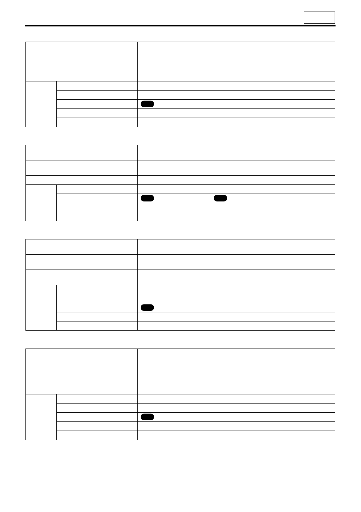
13
13-47
P125D: Rail Pressure M/V 2 (Long Short) (warning lamp flashes: 63)
P1335: Revolution & Position Sensor (warning lamp flashes: 14)
P1460: Auxiliary Brake M/V 1 (warning lamp flashes: 93)
P1462: Auxiliary Brake M/V 1 (warning lamp flashes: 93)
Generation condition
MPROP2 (rail pressure control valve) circuit remains shorted to ground as detect-
ed for 10 seconds.
Recoverability
System recovers (power is re-supplied to electronic control unit) if signal becomes
normal when starter switch is turned OFF (2 minutes or more) → ON.
Control effected by electronic control unit Engine is stopped 50 seconds after the diagnosis code is generated.
Inspection
Service data 0C: Difference Common Rail Pressure
Actuator test B9: Fuel Leak Check
Electronic control unit connector : MPROP2 (rail pressure control valve)
Electrical equipment #574: MPROP2 (rail pressure control valve)
Electric circuit diagram MPROP2 (rail pressure control valve) system
Generation condition
No signal from engine speed sensor and cylinder recognition sensor while starter
switch (S signal) is input for 10.2 seconds.
Recoverability
System recovers when signals are input from engine speed sensor or cylinder
recognition sensor.
Control effected by electronic control unit No specific control is effected.
Inspection
Service data 01: Engine Revolution
Electronic control unit connector : Engine speed sensor, : Cylinder recognition sensor
Electrical equipment #263: Engine speed sensor, #320: Cylinder recognition sensor
Electric circuit diagram Engine speed sensor and cylinder recognition sensor systems
Generation condition
Current flowing to Powertard solenoid valve remains above the specified value
for 1 second.
Recoverability
System recovers when the current flowing to Powertard solenoid valve remains
below the specified value for 1 second.
Control effected by electronic control unit
• Operation of auxiliary brake is stopped.
• Auto cruise control is stopped.
Inspection
Service data 80: Powertard M/V
Actuator test AC: Powertard M/V
Electronic control unit connector : Powertard solenoid valve
Electrical equipment #571: Powertard solenoid valve
Electric circuit diagram Powertard solenoid valve system
Generation condition
Powertard solenoid valve circuit shorted to ground or open-circuited (driving ter-
minal is at low level when turned OFF) as detected for 1 second.
Recoverability
System recovers when Powertard solenoid valve circuit remains normal (driving
terminal is at high level when turned OFF) for 1 second.
Control effected by electronic control unit
• Operation of auxiliary brake is stopped.
• Auto cruise control is stopped.
Inspection
Service data 80: Powertard M/V
Actuator test AC: Powertard M/V
Electronic control unit connector : Powertard solenoid valve
Electrical equipment #571: Powertard solenoid valve
Electric circuit diagram Powertard solenoid valve system
14
07 08
15
15
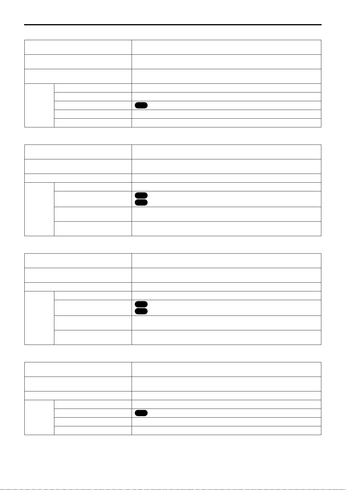
13-48
P1463: Auxiliary Brake M/V 1 (warning lamp flashes: 93)
P1562: Sensor Supply Voltage 1 (warning lamp flashes: 81)
P1563: Sensor Supply Voltage 1 (warning lamp flashes: 81)
P1567: Sensor Supply Voltage 2 (warning lamp flashes: 81)
Generation condition
Powertard solenoid valve circuit shorted to battery (driving terminal is at high lev-
el when turned ON) as detected for 1 second.
Recoverability
System recovers when Powertard solenoid valve circuit remains normal (driving
terminal is at low level when turned ON) for 1 second.
Control effected by electronic control unit
• Operation of auxiliary brake is stopped.
• Auto cruise control is stopped.
Inspection
Service data 80: Powertard M/V
Actuator test AC: Powertard M/V
Electronic control unit connector : Powertard solenoid valve
Electrical equipment #571: Powertard solenoid valve
Electric circuit diagram Powertard solenoid valve system
Generation condition
Circuit voltage (sensor supply voltage 1) in electronic control unit remains abnor-
mally low for 0.5 second.
Recoverability
System recovers when circuit voltage (sensor supply voltage 1) in electronic con-
trol unit becomes normal.
Control effected by electronic control unit No specific control is effected. Failure occurs only to circuit abnormality.
Inspection
Service data 24: Accel Pedal Sensor Voltage 1, 28: Idle Volume Voltage
Electronic control unit connector
: Accelerator pedal position sensor 1,
: Idling speed adjustment potentiometer
Electrical equipment
#157: Idling speed adjustment potentiometer, #324: Accelerator pedal position
sensor 1
Electric circuit diagram
Accelerator pedal position sensor 1 and idling speed adjustment potentiometer
systems
Generation condition
Circuit voltage (sensor supply voltage 1) in electronic control unit remains abnor-
mally high for 0.5 second.
Recoverability
System recovers when circuit voltage (sensor supply voltage 1) in electronic con-
trol unit becomes normal.
Control effected by electronic control unit No specific control is effected. Failure occurs only to circuit abnormality.
Inspection
Service data 24: Accel Pedal Sensor Voltage 1, 28: Idle Volume Voltage
Electronic control unit connector
: Accelerator pedal position sensor 1,
: Idling speed adjustment potentiometer
Electrical equipment
#157: Idling speed adjustment potentiometer, #324: Accelerator pedal position
sensor 1
Electric circuit diagram
Accelerator pedal position sensor 1 and idling speed adjustment potentiometer
systems
Generation condition
Circuit voltage (sensor supply voltage 2) in electronic control unit remains abnor-
mally low for 0.5 second.
Recoverability
System recovers when circuit voltage (sensor supply voltage 2) in electronic con-
trol unit becomes normal.
Control effected by electronic control unit No specific control is effected. Failure occurs only to circuit abnormality.
Inspection
Service data 25: Accel Pedal Sensor Voltage 2, 26: Boost Pressure
Electronic control unit connector : Accelerator pedal position sensor 2
Electrical equipment #318: Boost pressure sensor, #324: Accelerator pedal position sensor 2
Electric circuit diagram Boost pressure sensor and accelerator pedal position sensor 2 systems
15
03
10
03
10
03
TROUBLESHOOTING <DIAGNOSIS USING Multi-Use Tester>
13
13-49
P1568: Sensor Supply Voltage 2 (warning lamp flashes: 81)
P1572: Sensor Supply Voltage 3 (warning lamp flashes: 81)
P1573: Sensor Supply Voltage 3 (warning lamp flashes: 81)
P1605: ECU System (EEPROM) (warning lamp flashes: 33)
P1606: ECU System (Software) (warning lamp flashes: 33)
Generation condition
Circuit voltage (sensor supply voltage 2) in electronic control unit remains abnor-
mally high for 0.5 second.
Recoverability
System recovers when circuit voltage (sensor supply voltage 2) in electronic con-
trol unit becomes normal.
Control effected by electronic control unit No specific control is effected. Failure occurs only to circuit abnormality.
Inspection
Service data 25: Accel Pedal Sensor Voltage 2, 26: Boost Pressure
Electronic control unit connector : Accelerator pedal position sensor 2
Electrical equipment #318: Boost pressure sensor, #324: Accelerator pedal position sensor 2
Electric circuit diagram Boost pressure sensor and accelerator pedal position sensor 2 systems
Generation condition
Circuit voltage (sensor supply voltage 3) in electronic control unit remains abnor-
mally low for 0.5 second.
Recoverability
System recovers when circuit voltage (sensor supply voltage 3) in electronic con-
trol unit becomes normal.
Control effected by electronic control unit No specific control is effected. Failure occurs only to circuit abnormality.
Inspection
Service data 0C: Difference Common Rail Pressure, 35: PTO Accel Sensor Voltage
Electronic control unit connector : Power take-off load sensor
Electrical equipment #317: Power take-off load sensor, #319: Common rail pressure sensor
Electric circuit diagram Power take-off load sensor and common rail pressure sensor systems
Generation condition
Circuit voltage (sensor supply voltage 3) in electronic control unit remains abnor-
mally high for 0.5 second.
Recoverability
System recovers when circuit voltage (sensor supply voltage 3) in electronic con-
trol unit becomes normal.
Control effected by electronic control unit No specific control is effected. Failure occurs only to circuit abnormality.
Inspection
Service data 0C: Difference Common Rail Pressure, 35: PTO Accel Sensor Voltage
Electronic control unit connector : Power take-off load sensor
Electrical equipment #317: Power take-off load sensor, #319: Common rail pressure sensor
Electric circuit diagram Power take-off load sensor and common rail pressure sensor systems
Generation condition Reading or writing error occurs during access.
Recoverability
System recovers (power is re-supplied to electronic control unit) if signal becomes
normal when starter switch is turned OFF → ON.
Control effected by electronic control unit No specific control is effected. Failure occurs only to circuit abnormality.
Inspection Other Replace engine electronic control unit.
Generation condition
Diagnosis code is generated under either of the following conditions.
• System overload occurs.
• Data processing time of engine electronic control unit has exceeded time-out
period (0.0655 second).
Recoverability
System recovers (power is re-supplied to electronic control unit) if signal becomes
normal when starter switch is turned OFF (2 minutes or more) → ON.
Control effected by electronic control unit Engine is stopped.
Inspection Other Replace engine electronic control unit.
03
06
06
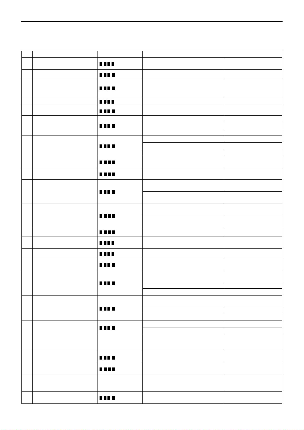
13-50
4. Multi-Use Tester Service Data
• It is possible to see service data and actuator tests simultaneously.
No. Item Data Inspection condition Requirement
01 Engine Revolution Racing (engine running)
Engine speed after engine
warm-up: 500 ± 25 rpm
02 Reference Injection Quantity Engine idling 5 to 20%
0C
Difference Common Rail
Pressure
Engine idling
Fuel injection quantity af-
ter engine warm-up:
Less than 30%
20 Actual EGR Position 1 See Gr17. –
21 VGT Position See Gr15. –
22
Accel Pedal Position
(unfiltered)
Accelerator pedal not pressed 0%
Accelerator pedal gradually pressed Value gradually increases.
Accelerator pedal fully pressed 100%
23
Accel Pedal Position
(filtered)
Accelerator pedal not pressed 0%
Accelerator pedal gradually pressed Value gradually increases.
Accelerator pedal fully pressed 100%
24
Accel Pedal Sensor
Voltage 1
Accelerator pedal gradually pressed
from released position
0.85 to 4.15 V
25
Accel Pedal Sensor
Voltage 2
Accelerator pedal gradually pressed
from released position
0.85 to 4.15 V
26 Boost Pressure
Starter switch ON (engine is stopped)
Value matches atmospher-
ic pressure indication.
Accelerator pedal pressed after engine
has started
Value gradually increases.
27
Boost Pressure Sensor
Voltage
Starter switch ON (engine is stopped)
1 V <altitude: 0 m>
0.92 V <altitude: 600 m>
Accelerator pedal pressed after engine
has started
Value gradually increases.
28 Idle Volume Voltage SLOW to FAST 3 to 1 V
29 Vehicle Speed Vehicle in motion
Value matches speedome-
ter indication.
2A Turbine Revolution See Gr15. –
2B Intake Air Temperature Engine cold
Value matches ambient
temperature indication.
2E Water Temperature
Engine cold
Value matches ambient
temperature indication.
Engine in process of warming up Value gradually increases.
Engine stopped after warming up Value gradually decreases.
2F Fuel Temperature (Inlet)
Engine cold
Value matches ambient
temperature indication.
Engine in process of warming up Value gradually increases.
Engine stopped after warming up Value gradually decreases.
30 Atmospheric Pressure
Altitude: 0 m 101 kPa
Altitude: 600 m 95 kPa
33 Q Adjustment Resistor No.
1/2/3/4/5/6/7/8/9/10/
11/NON
–
Number matches number
marked on fuel injection
rate adjustment resistor.
34 PTO Accel Position
When power take-off is used (MIN to
MAX)
0 to 100%
35 PTO Accel Sensor Voltage
When power take-off is used (MIN to
MAX)
1 to 3.0 V
36 PTO Adjustment Resistor No. 1/2/3/4/5/6/7/8/NON Governor control switch ON
Number matches number
marked on power take-off
resistor.
37 Power Supply Voltage Starter switch ON
Value matches battery
voltage.
.rpm
. %
. %
.
. %
. %
. %
. V
. V
. kPa
. V
. V
.km/h
.rpm
. °C
. °C
. °C
. kPa
. %
. V
. V
TROUBLESHOOTING <DIAGNOSIS USING Multi-Use Tester>
13
13-51
71 Starter SW (S) ON/OFF
Engine cranked by means of starter
switch
ON
Starter switch in position except
START
OFF
72 Starter SW (M) ON/OFF
Starter switch in ON position ON
Starter switch in position except ON OFF
73 Accel SW ON/OFF
Accelerator pedal not pressed ON
Accelerator pedal pressed OFF
74 Powertard SW 1 ON/OFF
Powertard switch (1st step): ON ON
Powertard switch (1st step): OFF OFF
75 Powertard SW 2 ON/OFF
Powertard switch (2nd step): ON ON
Powertard switch (2nd step): OFF OFF
76 Clutch SW ON/OFF
Clutch pedal pressed ON
Clutch pedal not pressed OFF
77 Neutral SW ON/OFF
Transmission not in neutral ON
Transmission in neutral OFF
78 Idle Up Cancel SW ON/OFF
Actuator test is performed
ON (5 times, for 1.5 sec.
each)
Actuator test is not performed OFF
[Actuator test] B8: Idle Up Cancel SW
7C PTO SW ON/OFF
Governor control switch ON ON
Governor control switch OFF OFF
7D Diagnosis SW ON/OFF
Diagnosis switch OFF
(with connector connected)
ON
Diagnosis switch ON
(with connector disconnected)
OFF
7E Memory Clear SW ON/OFF
Memory clear switch OFF
(with connector connected)
ON
Memory clear switch ON
(with connector disconnected)
OFF
7F Auxiliary Brake SW 1 ON/OFF
Operated under following conditions
• Accelerator and clutch pedals are
pressed
• Transmission in neutral position
ON
Other than above conditions OFF
80 Powertard M/V ON/OFF
Powertard operating ON
Powertard not operating OFF
[Actuator test] A6: Powertard M/V
82 VGT M/V 1 ON/OFF See Gr15. –
83 VGT M/V 2 ON/OFF See Gr15. –
84 VGT M/V 3 ON/OFF See Gr15. –
85 Auxiliary Brake Indicator Lamp ON/OFF
Auxiliary brake operating ON
Auxiliary brake not operating OFF
[Actuator test] AE: Auxiliary Brake Indicator Lamp
88 Starter Safety Relay ON/OFF See Gr54. –
89 EDU Power Relay ON/OFF See Gr17. –
8A MIL LAMP ON/OFF
Starter switch ON (engine not started) ON
No error after engine startup OFF
[Actuator test] B3: MIL Lamp
8B Diagnosis Lamp ON/OFF
Starter switch ON (engine not started) ON
No error after engine startup OFF
[Actuator test] B4: Diagnosis Lamp
No. Item Data Inspection condition Requirement

13-52
5. Actuator Tests Performed Using Multi-Use Tester
• It is possible to see service data and actuator tests simultaneously.
No. Item Explanation Confirmation method
A1 EGR 1
See Gr17. –A2 EGR 2
A3 EGR 3
A9 VGT M/V 1
See Gr15. –AA VGT M/V 2
AB VGT M/V 3
AC Powertard M/V
Repeatedly turn each valve ON and OFF (5 times, for
1.5 sec. each).
[Can be executed when the following conditions are
satisfied]
• Vehicle: stationary (vehicle speed 0 km/h)
• Starter switch: ON
• Engine: stopped
Check by the operating
sound when Powertard so-
lenoid valve is turned ON/
OFF.
[Service data]
80: Powertard M/V
AE Auxiliary Brake Indicator Lamp
Repeatedly turn Auxiliary brake indicator lamp ON and
OFF (5 times, for 1.5 sec. each).
[Can be executed when the following conditions are
satisfied]
• Vehicle: stationary (vehicle speed 0 km/h)
• Starter switch: ON
• Engine: stopped
Check that the indicator
lamp surely illuminates or
goes out as commanded.
[Service data]
85: Auxiliary Brake Indica-
tor Lamp
B1 Starter Safety Relay See Gr54. –
B2 EDU Relay See Gr17. –
B3 MIL LAMP
Repeatedly turn the engine control warning lamp ON
and OFF (5 times, for 1.5 sec. each).
[Can be executed when the following conditions are
satisfied]
• Starter switch: ON
• Engine: stopped
ON/OFF condition of warn-
ing lamp (orange)
[Service data]
8A: MIL LAMP
B4 Diagnosis Lamp
ON/OFF condition of warn-
ing lamp (red)
[Service data]
8B: Diagnosis Lamp
B8 Idle Up Cancel SW
Repeatedly turn idle up cancel switch ON and OFF (5
times, for 1.5 sec. each).
[Can be executed when the following conditions are
satisfied]
• Vehicle: stationary (vehicle speed 0 km/h)
• Transmission: Neutral
Check that the engine
idling speed remains at low
idling.
[Service data]
78: Idle Up Cancel SW
B9 Fuel Leak Check
Increase rail pressure for a certain period of time
[Can be executed when the following conditions are
satisfied]
• Vehicle: stationary (vehicle speed 0 km/h)
• Transmission: Neutral
• Engine: idling
Check that no fuel leaks
from fuel system (pipe and
hose).
BA VGT Test See Gr15. –
BB Injector Test 1
Selected injector magnetic valve forcibly deactivated
[Can be executed when the following conditions are
satisfied]
• Vehicle: stationary (vehicle speed 0 km/h)
• Engine speed: Below 1500 rpm
• Transmission: Neutral
• No active diagnosis code generated
Check that injector mag-
netic valve for No. 1 cylin-
der stops operating.
BC Injector Test 2
Check that injector mag-
netic valve for No. 2 cylin-
der stops operating.
BD Injector Test 3
Check that injector mag-
netic valve for No. 3 cylin-
der stops operating.
BE Injector Test 4
Check that injector mag-
netic valve for No. 4 cylin-
der stops operating.
BF Injector Test 5
Check that injector mag-
netic valve for No. 5 cylin-
der stops operating.
C0 Injector Test 6
Check that injector mag-
netic valve for No. 6 cylin-
der stops operating.
TROUBLESHOOTING <DIAGNOSIS USING Multi-Use Tester>

M E M O
13-53
13
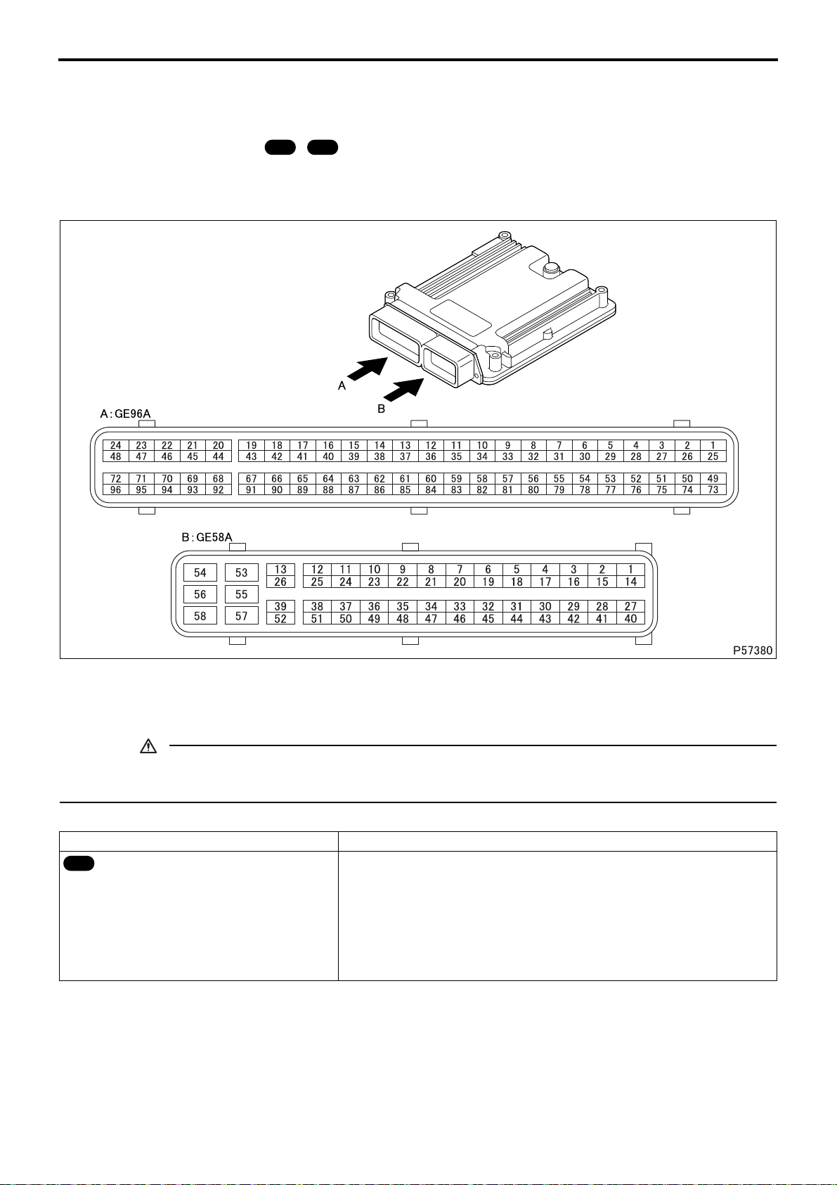
13-54
6. Inspections Performed at Electronic Control Unit Connectors
• These inspections aid troubleshooting by enabling you to check whether electronic control unit signals are being
correctly transmitted via the vehicle harness and connectors.
The white-on-black numbers ( , , and so on) correspond to the similarly printed reference numbers in
section “3. Inspections Based on Diagnosis Codes”.
6.1 Electronic control unit connector terminal layout
6.2 Inspection instructions
• Some inspections are performed with the connectors removed. Others are performed with the connectors fitted.
Observe the following caution:
CAUTION
• Do not touch any terminal except those specified for the inspection. Be particularly careful not to cause
short circuits between terminals using the tester probes.
Check item Measurement method
Resistance of intake air temperature sensor 1
[Conditions]
• Starter switch OFF
• Disconnect connector. Perform inspection on vehicle-side connector.
[Requirements]
Terminals: A63-A32
• 0°C: 15 kΩ
• 20°C: 6.514 kΩ
• 80°C: 0.874 kΩ
01 02
01
+3.78
–2.94
+1.437
–1.147
+0.136
–0.115
TROUBLESHOOTING <DIAGNOSIS USING Multi-Use Tester>
13
13-55
Check item Measurement method
Resistance of water temperature sensor
[Conditions]
• Starter switch OFF
• Disconnect connector. Perform inspection on vehicle-side connector.
[Requirements]
Terminals: A40-A41
• 20°C: 2.45 ± 0.14 kΩ
• 80°C: 0.32 kΩ (reference value)
• 110°C: 147.1 ± 2 kΩ
Output voltage of accelerator pedal position
sensor
[Conditions]
• Starter switch ON
• Vehicle-side harness connected (Perform inspection on back of connector.)
[Requirements]
Terminals (+)-(–):
B34-B33 (accelerator pedal position sensor 1)
B46-B45 (accelerator pedal position sensor 2)
• With accelerator pedal not pressed: 0.85 ± 0.1 V
• With accelerator pedal pressed: 4.15 ± 0.1 V
Resistance of fuel temperature sensor
[Conditions]
• Starter switch OFF
• Disconnect connector. Perform inspection on vehicle-side connector.
[Requirements]
Terminals: A89-A65
• 20°C: 2.5 ± 0.25 kΩ
• 80°C: 0.32 ± 0.02 kΩ
• 110°C: 0.144 ± 0.01 kΩ
Resistance of injector magnetic valve
[Conditions]
• Starter switch OFF
• Disconnect connector. Perform inspection on vehicle-side connector.
[Requirements]
Terminals:
A72-A23 (injector magnetic valve: No. 1 cylinder)
A70-A22 (injector magnetic valve: No. 2 cylinder)
A71-A46 (injector magnetic valve: No. 3 cylinder)
A94-A47 (injector magnetic valve: No. 4 cylinder)
A96-A24 (injector magnetic valve: No. 5 cylinder)
A95-A48 (injector magnetic valve: No. 6 cylinder)
• 0.21 to 0.295 Ω
Output voltage of Power take-off load sensor
[Conditions]
• Starter switch ON
• Vehicle-side harness connected (Perform inspection on back of connec-
tor.)
[Requirements]
Terminals (+)-(–): A15-A16
• Idling: 0.85 ± 0.1 V
• Full-load: 3.0 ± 0.1 V
Resistance of engine speed sensor
[Conditions]
• Starter switch OFF
• Disconnect connector. Perform inspection on vehicle-side connector.
[Requirements]
Terminals: A10-A9
• 2.2 ± 0.2 Ω (25°C)
Resistance of cylinder recognition sensor
[Conditions]
• Starter switch OFF
• Disconnect connector. Perform inspection on vehicle-side connector.
[Requirements]
Terminals: A59-A83
• 860 ± 86 Ω
Output voltage of vehicle speed sensor
[Conditions]
• Starter switch ON
• Vehicle-side harness connected (Perform inspection on back of connector.)
• Turn wheels slowly using chassis dynamometer.
[Requirements]
Terminals (+)-(–): A67-chassis ground
• High pulse voltage: 8 ± 1 V
• Low pulse voltage: 0.5 V or lower
02
03
04
05
06
07
08
09

13-56
Output voltage of idling speed adjustment
potentiometer
[Conditions]
• Starter switch ON
• Vehicle-side harness connected (Perform inspection on back of connector.)
[Requirements]
Terminals (+)-(–): A12-A36
• AUTO position: 4.0 ± 0.1 V
• SLOW position: 3.0 ± 0.2 V
• FAST position: 1.0 ± 0.1 V
Operating voltage of accelerator pedal switch
[Conditions]
• Starter switch OFF
• Disconnect connector. Perform inspection on vehicle-side connector.
[Requirements]
Terminals (+)-(–): A20-chassis ground
• With accelerator pedal pressed: There is no continuity.
• With accelerator pedal not pressed: There is continuity.
Resistance of fuel injection rate adjustment
resistor
[Conditions]
• Starter switch OFF
• Disconnect connector. Perform inspection on vehicle-side connector.
[Requirements]
Terminals: A35-A88
• No. 1 resistor: 270 ± 13.5 Ω
• No. 2 resistor: 510 ± 25.5 Ω
• No. 3 resistor: 820 ± 41 Ω
• No. 4 resistor: 1300 ± 65 Ω
• No. 5 resistor: 2000 ± 100 Ω
• No. 6 resistor: 3300 ± 165 Ω
• No. 7 resistor: 5600 ± 280 Ω
• No. 8 resistor: 15000 ± 750 Ω
• No. 9 resistor: 390 ± 19.5 Ω
• No. 10 resistor: 4300 ± 215 Ω
• No. 11 resistor: 9100 ± 455 Ω
Resistance of Power take-off resistor
[Conditions]
• Starter switch OFF
• Disconnect connector. Perform inspection on vehicle-side connector.
[Requirements]
Terminals: A43-A19
• No. 1 resistor: 270 ± 13.5 Ω
• No. 2 resistor: 510 ± 25.5 Ω
• No. 3 resistor: 820 ± 41 Ω
• No. 4 resistor: 1300 ± 65 Ω
• No. 5 resistor: 2000 ± 100 Ω
• No. 6 resistor: 3300 ± 165 Ω
• No. 7 resistor: 5600 ± 280 Ω
• No. 8 resistor: 15000 ± 750 Ω
Resistance of MPROP
(rail pressure control valve)
[Conditions]
• Starter switch OFF
• Disconnect connector. Perform inspection on vehicle-side connector.
[Requirements]
Terminals:
• A69-A21, A69-A2, A3-A21, A3-A2 (MPROP1)
• A27-A4, A27-B38, B52-A4, B52-B38 (MPROP2)
• 2.6 to 3.15 Ω
Voltage of Powertard solenoid valve
[Conditions]
• Starter switch OFF
• Disconnect connector. Perform inspection on vehicle-side connector.
[Requirements]
Terminals: A74-A5
• 32.6 to 39.8 Ω (engine oil temperature: 25°C)
Resistance of controller area network resistor
[Conditions]
• Starter switch OFF
• Disconnect connector. Perform inspection on vehicle-side connector.
[Requirements]
Terminals: B11-B12, B5-B6
• 120 ± 6 Ω
10
11
12
13
14
15
16
TROUBLESHOOTING <DIAGNOSIS USING Multi-Use Tester>

M E M O
13-57
13
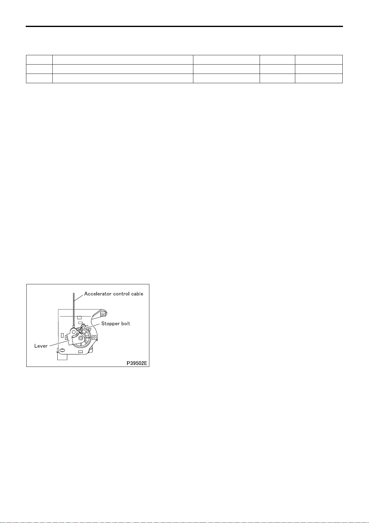
13-58
1. Inspecting No-load Minimum and Maximum Speeds
Service standards
1.1 Work before inspection
• Before starting the inspection and adjustment, carry out the fol-
lowing preparatory steps.
• Put the transmission in neutral.
• Turn the steering wheel in neutral position.
• Turn off all lamps and accessories.
• Attach a Multi-Use Tester.
• Warm up the engine until the engine coolant temperature is ap-
proximately 80 to 95°C.
(Verify from Service Data “2E: Water Temperature”)
1.2 No-load minimum speed
[Inspection]
• With the accelerator pedal released, measure the engine speed.
• If the measurement deviates from the standard value, check for
an installed condition of the accelerator control cable and accel-
erator link. (See “ENGINE CONTROL”.)
• If the cable and link are found to be normal, check for the accel-
erator pedal switch
*a
, accelerator pedal position sensor
*a
, sup-
ply pump
*b
and engine electronic control unit
*b
.
(*a: See “ENGINE CONTROL”, *b: Contact Bosch Service Sta-
tion for repair.)
1.3 No-load maximum speed
[Inspection]
• Measure the engine speed with the accelerator pedal pressed
against the stopper bolt.
• If the measurement deviates from the standard value, check for
an installed condition of the accelerator control cable and accel-
erator link. (See “ENGINE CONTROL”.)
• If the cable and link are found to be normal, check for the accel-
erator pedal switch
*a
, accelerator pedal position sensor
*a
, sup-
ply pump
*b
and engine electronic control unit
*b
.
(*a: See “ENGINE CONTROL”, *b: Contact Bosch Service Sta-
tion for repair.)
[Adjustment]
• If the measurement deviates from the standard value, adjust the
stopper bolt to change the accelerator pedal travel until the opti-
mum engine speed is reached with the pedal pressed.
• If it cannot be adjusted within the standard value by using the
stopper bolt, check for an installed condition of the accelerator
control cable and accelerator link. (See “ENGINE CONTROL”.)
• If the cable and link are found to be normal, check for the accel-
erator pedal switch
*a
, accelerator pedal position sensor
*a
, sup-
ply pump
*b
and engine electronic control unit
*b
.
(*a: See “ENGINE CONTROL”, *b: Contact Bosch Service Sta-
tion for repair.)
• After the adjustment, make sure that the accelerator pedal
moves smoothly by firmly pressing the pedal 10 to 15 times until
it contacts the stopper bolt.
Location Maintenance item Standard value Limit Remedy
– No-load minimum speed (idling speed) 450 to 500 rpm – Inspect
– No-load maximum speed 2330 to 2370 rpm – Inspect
ON-VEHICLE INSPECTION AND ADJUSTMENT
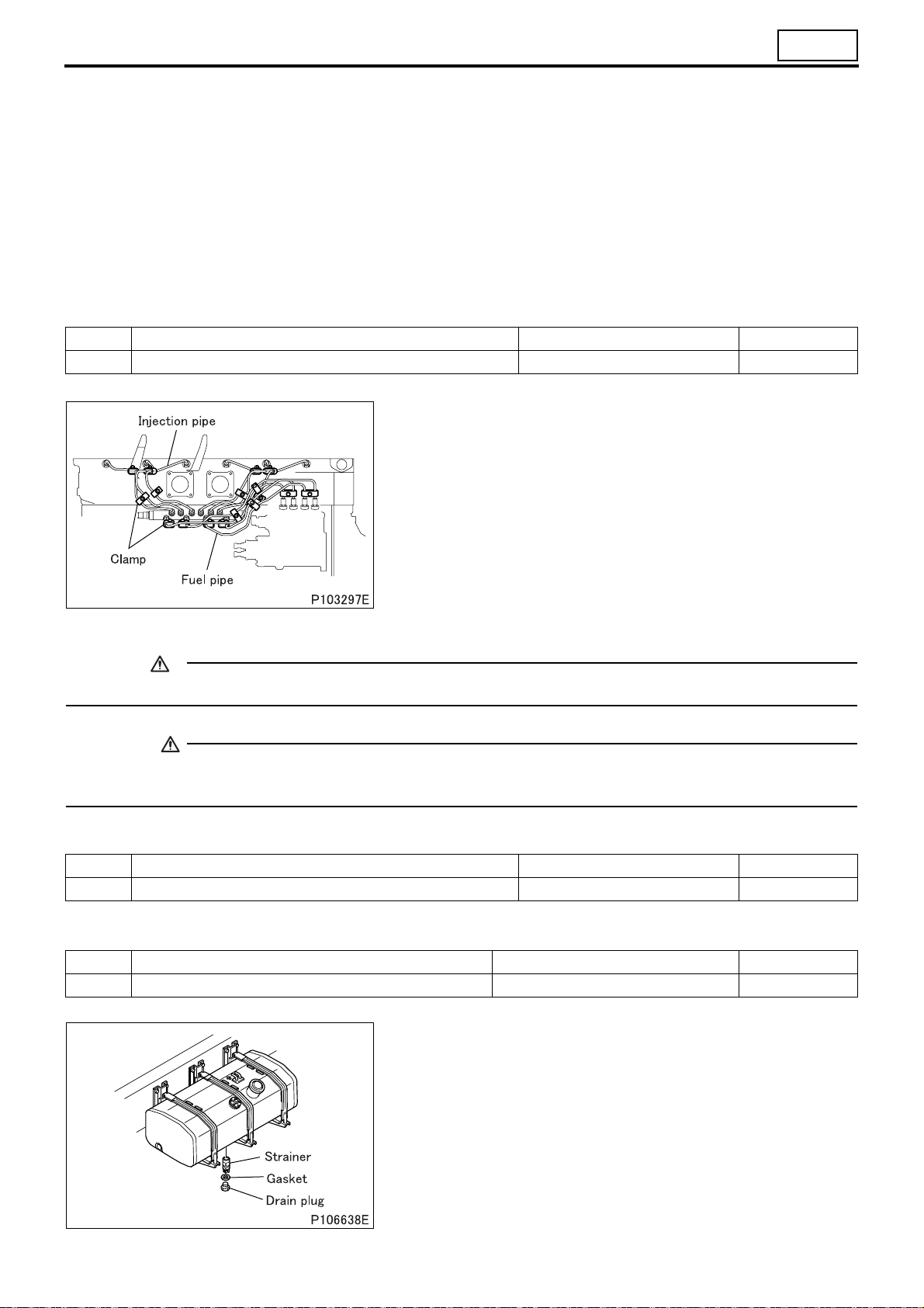
13
13-59
• If it does not move smoothly, check for an installed condition of
the accelerator control cable and accelerator link. (See “EN-
GINE CONTROL”.)
2. Inspection of Fuel Leakage
• Check if there is no fuel leakage from the fuel tank, fuel filter, supply pump, common rail, injector and fuel piping.
If there is a fuel leakage, replace the pipe or hose and tighten to the specified torque. If fuel leaks from joint, re-
tighten the bolts, nuts and clamps to the specified torque. (See later section.)
3. Inspection of Injection Pipe and Fuel Pipe Mounting Clamp
Tightening torque (Unit: N·m {kgf·m})
• Visually check the clamp appearance and make sure there is no
cracks or damages at the rubber part of the clamps.
• If there is any abnormality, replace the clamp.
• Check for looseness in the clamp mounting bolt or nuts. If there
is looseness, tighten the bolts and nuts to the specified torque.
4. Draining of Deposit in Fuel Tank
DANGER
• Do not allow any flames or sources of heat near the fuel tank, as it may explode.
WARNING
• Fuel is highly flammable. Keep it away from flames and sources of heat.
• Thoroughly wipe up any spilled fuel, otherwise it may catch fire.
Tightening torque (Unit: N·m {kgf·m})
Lubricant and/or sealant
[Removal]
• Drain the deposit in the fuel tank by removing the drain plug,
gasket and strainer from the fuel tank.
[Installation]
• Install the strainer and gasket to the fuel tank. Tighten the drain
plug to the specified torque.
Mark Parts to be tightened Tightening torque Remarks
– Bolt or nut (clamp mounting) 17.6 to 21.6 {1.8 to 2.2} –
Mark Parts to be tightened Tightening torque Remarks
– Drain plug 127 {13} Sealant
Location Points of application Specified lubricant and/or sealant Quantity
– Seat surface of drain plug Seal end No. 22 As required
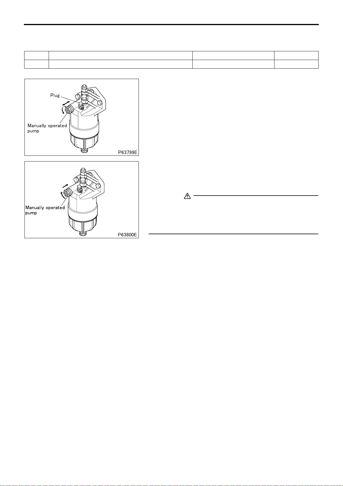
13-60
5. Air-bleeding of Fuel System
Tightening torque (Unit: N·m {kgf·m})
• Loosen one of the plugs on the fuel filter.
• Turn the knob of the manually operated pump counterclockwise.
When the knob jumps out, push the knob to feed fuel.
• Continue pumping until fuel with no bubbles of air comes out of
the plug.
• With no air bubbles coming out with fuel, tighten the plug to the
specified torque.
• Continue operating the pump until there is strong pumping resis-
tance.
• While pushing the knob of the manually operated pump, screw it
in to the right to fix.
• Wipe up all spilled fuel, then start the engine.
• Check that no fuel leakage occurs.
WARNING
• Fuel is highly flammable. Keep it away from flames and
sources of heat.
• Be sure to wipe up all spilled fuel. Unless it is wiped up, it
could catch fire.
Mark Parts to be tightened Tightening torque Remarks
– Plug 9.8 ± 2.0 {1.0 ± 0.2} –
ON-VEHICLE INSPECTION AND ADJUSTMENT
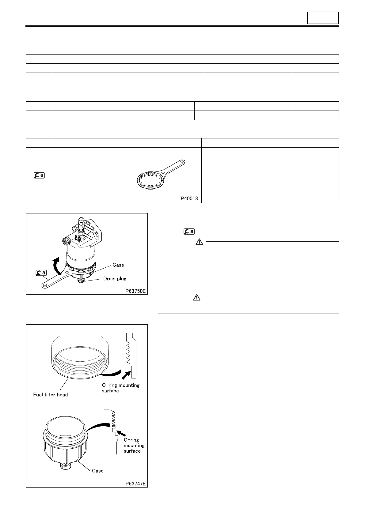
13
13-61
6. Fuel Filter Replacement
Tightening torque (Unit: N·m {kgf·m})
Lubricant and/or sealant
Special tools
[Removal]
• Drain fuel from the case by loosening the drain plug.
• Us
ing
, remove the case.
WARNING
• Fuel is highly flammable. Keep it away from flames and
sources of heat.
• Thoroughly wipe up any spilled fuel. Otherwise, it may
catch fire.
CAUTION
• Be careful not to damage the case.
[Installation]
• Clean the surface of the fuel filter head and case where the O-
ring is to be mounted.
Mark Parts to be tightened Tightening torque Remarks
– Drain plug 2 ± 0.5 {0.2 ± 0.05} –
– Case 18 to 20 {1.8 to 2.0} –
Mark Points of application Specified lubricant and/or sealant Quantity
– O-ring Engine oil As required
Mark Tool name and shape Part No. Application
Filter wrench MH063201 Removal and installation of case
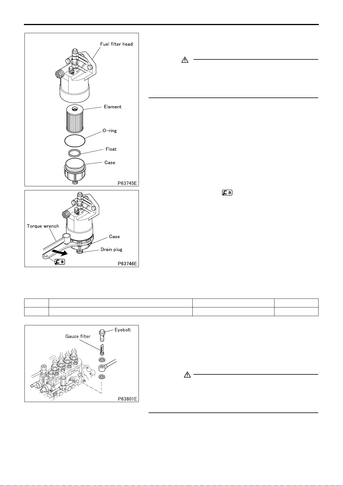
13-62
• Replace the filter element and O-rings with new parts.
• Apply a thin coat of engine oil to the O-rings. Install the O-rings
onto the case.
CAUTION
• The use of non-genuine filter elements will lead to engine
problems. Be sure to use only genuine parts.
• To help prevent fuel injection problems, keep the fuel filter
and hoses free from contamination.
• Install a torque wrench to and tighten the case to the spec-
ified torque.
• Tighten the drain plug to the specified torque. With the plug cor-
rectly installed, bleed air from the fuel system.
• Start the engine and ensure that there is no fuel leakage.
• If there is fuel leakage, remove and install the fuel filter correctly.
7. Cleaning of Gauze Filter
Tightening torque (Unit: N·m {kgf·m})
• Remove the eyebolt in the middle of fuel piping.
• Pull out the gauze filter from the removed eyebolt.
• Wash the gauze filter with light oil.
• After washing, install the gauze filter in the reverse order.
• Bleed air from the fuel system.
• Start the engine and check for fuel leakage.
WARNING
• Thoroughly wipe up any spilled fuel, otherwise it may catch
fire.
• Fuel is highly flammable. Keep it away from flames and
sources of heat.
Mark Parts to be tightened Tightening torque Remarks
– Eyebolt 25 to 29 {2.5 to 3.0} –
ON-VEHICLE INSPECTION AND ADJUSTMENT
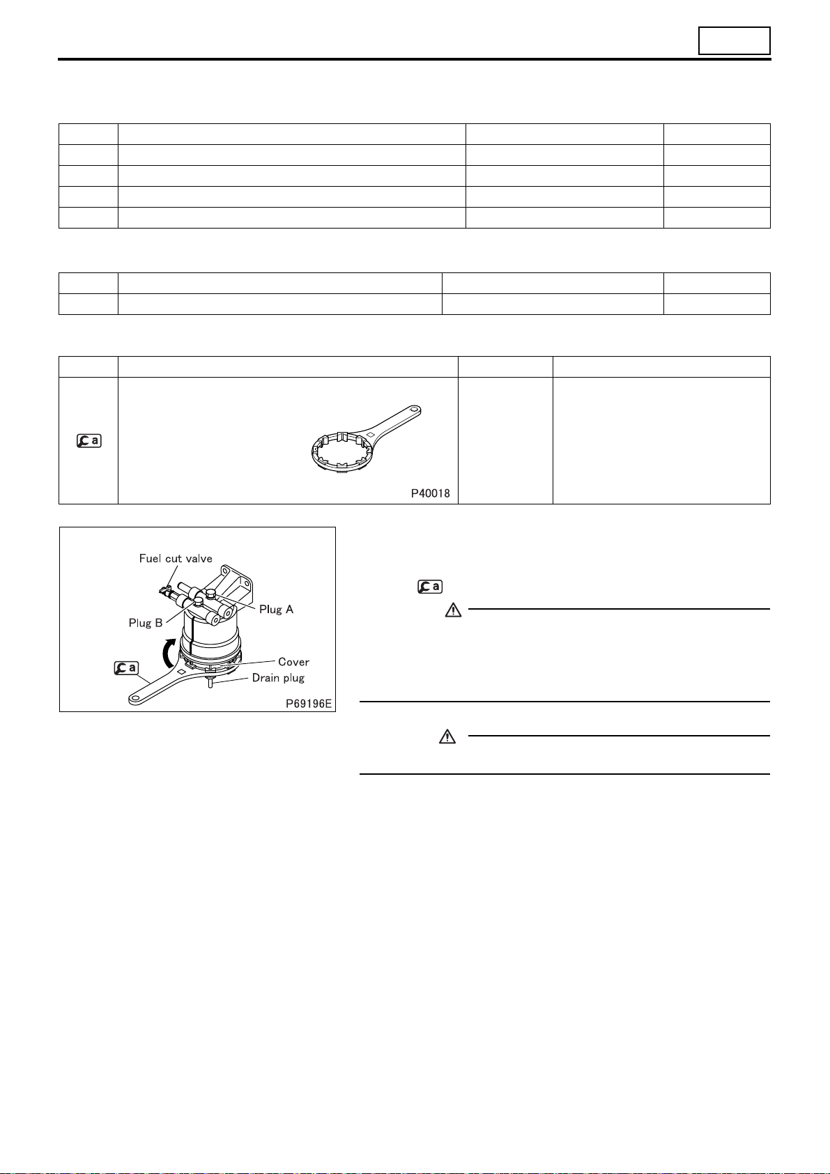
13
13-63
8. Water Separator Element Replacement
Tightening torque (Unit: N·m {kgf·m})
Lubricant and/or sealant
Special tools
[Removal]
• Loosen plugs A and B and then loosen the drain plug. Next, dis-
charge fuel from the water separator.
• Us
ing
, remove the cover.
WARNING
• Fuel is highly flammable. Keep it away from flames and
sources of heat.
• Thoroughly wipe up any spilled fuel. Otherwise, it may
catch fire.
CAUTION
• Use care not to damage the cover.
Mark Parts to be tightened Tightening torque Remarks
– Drain plug 1.47 ± 0.3 {0.15 ± 0.03} –
– Cover 19.6 ± 2.5 {2.0 ± 0.3} –
– Plug A 12.3 ± 2.5 {1.25 ± 0.3} –
– Plug B 17.2 ± 2.5 {1.75 ± 0.3} –
Mark Points of application Specified lubricant and/or sealant Quantity
– O-ring Engine oil As required
Mark Tool name and shape Part No. Application
Filter wrench MH063201 Removal and installation of cover
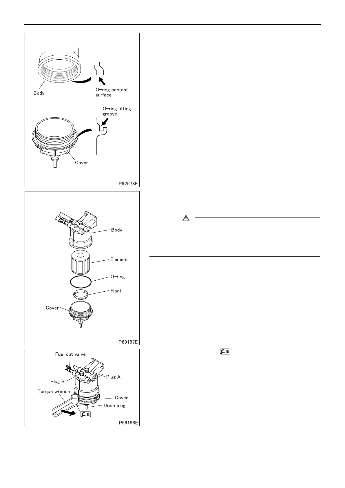
13-64
[Installation]
• Clean the surface of the water separator body, against which O-
ring abuts, and the O-ring groove in the cover.
• Replace the filter element and O-ring with new parts.
• Apply a thin coat of engine oil to the O-ring. Install the O-ring
onto the case.
CAUTION
• The use of non-genuine filter elements will lead to engine
problems. Be sure to use only genuine parts.
• To help prevent fuel injection problems, keep the water sep-
arator and fuel hoses free from contamination.
• Install torque wrench to and tighten the case to the speci-
fied torque.
• Tighten the drain plug and plugs A, B to the specified torque.
With the plug correctly installed, bleed air from the fuel system.
• Start the engine and ensure that there is no fuel leakage.
• If there is fuel leakage, remove and install the water separator
correctly.
ON-VEHICLE INSPECTION AND ADJUSTMENT
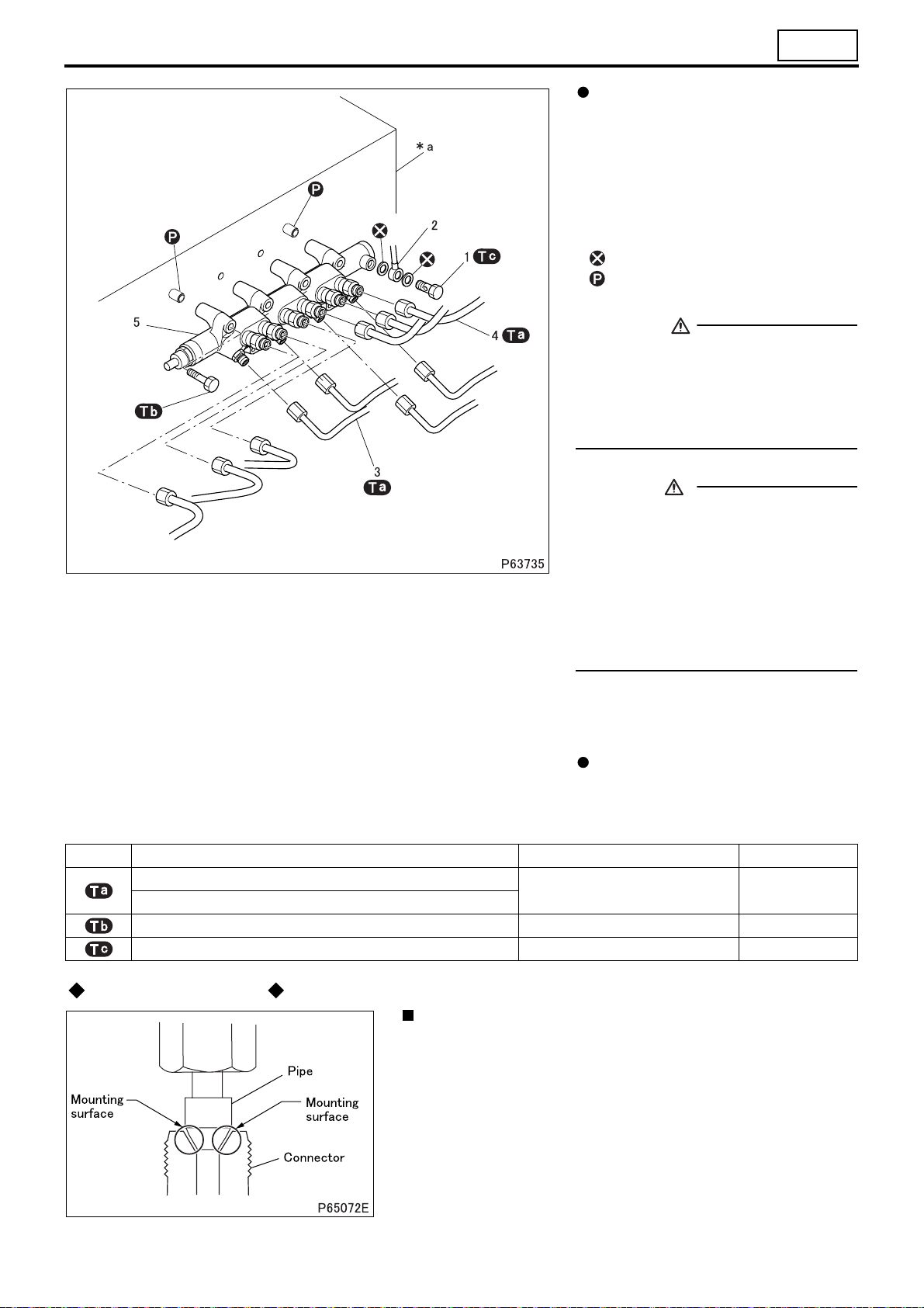
13
13-65
Removal sequence
1 Eyebolt
2 Fuel return pipe
3 Fuel pipe
4 Injection pipe
5 Common rail
*
a: Crankcase
: Non-reusable parts
: Locating pin
WARNING
• Fuel is highly flammable. Do not
handle it near flames or heat.
• Spilled fuel may catch fire and
therefore, must be wiped off com-
pletely.
CAUTION
• Any contamination of the common
rail, even if it is minor, will greatly
affect the performance of the en-
gine. After removing pipes or other
parts, plug the openings with cov-
ers. Wash eyebolts and gaskets in
light oil and keep them away from
contaminants.
• Contact Bosch Service Station for any
service needs of the common rail.
Installation sequence
Follow the removal sequence in reverse.
Tightening torque (Unit: N·m {kgf·m})
Installation procedure
Installation: Mitsubishi 6M70 Fuel pipe and injection pipe
• Ensure that the pipe and mounting surfaces of the connector are
flat and free from damage.
• Bring the pipe into intimate contact with mounting surfaces of the
connector evenly, and temporarily tighten it without applying an
excessive force.
• Tighten it to the specified torque after temporary tightening.
Mark Parts to be tightened Tightening torque Remarks
Fuel pipe
29 to 34 {3.0 to 3.5} –
Injection pipe
Bolt (common rail mounting) 54 {5.5} –
Eyebolt (fuel return pipe mounting) 30 to 35 {3.1 to 3.6} –
M
ITSUBISHI 6M70 COMMON RAIL
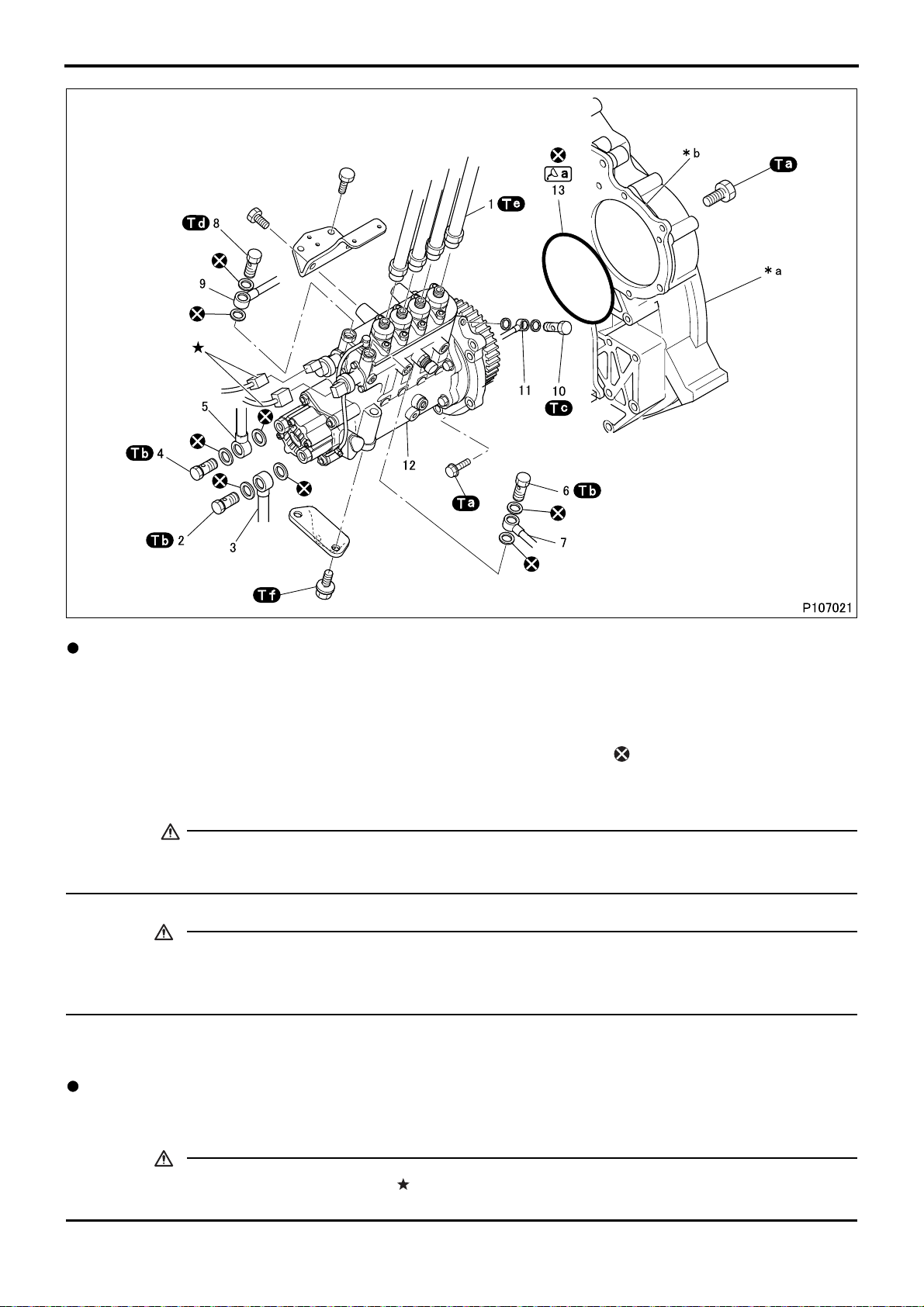
13-66
Removal sequence
WARNING
• Fuel is highly flammable. Do not handle it near flames or heat.
• Spilled fuel may catch fire and therefore, must be wiped off completely.
CAUTION
• Any contamination of the supply pump, even if it is minor, will greatly affect the performance of the en-
gine. After removing pipes, hoses, or other parts, plug the openings with covers. Wash eyebolts and new
gaskets in light oil and keep them away from contaminants.
• Contact Bosch Service Station for any service needs of the supply pump.
Installation sequence
Follow the removal sequence in reverse.
CAUTION
• Make sure that the harness (marked with “ ”) of MPROP (rail pressure control valve) is connected to the
supply pump before starting the engine. Starting the engine without connection causes a malfunction.
1 Fuel pipe
2 Eyebolt
3 Fuel suction pipe
4 Eyebolt
5 Fuel feed pipe
6 Eyebolt
7 Fuel feed pipe
8 Over flow valve
9 Fuel return pipe
10 Eyebolt
11 Oil pipe
12 Supply pump
13 O-ring
*
a: Flywheel housing
*
b: Rear plate
: Non-reusable parts
M
ITSUBISHI 6M70 FUEL SUPPLY PUMP
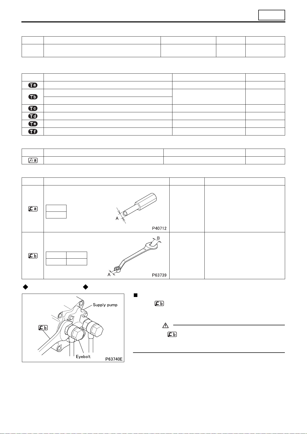
13
13-67
Service standards
Tightening torque (Unit: N·m {kgf·m})
Lubricant and/or sealant
Special tools (Unit: mm)
Removal procedure
Removal: Fuel suction pipe and fuel feed pipe
• Apply (width across flats: 24 mm) to the connector of the
supply pump as a stopper, and then loosen the eyebolt to re-
move the fuel suction pipe and fuel feed pipe.
CAUTION
• Do not use except for a stopper of the fuel suction pipe
and fuel feed pipe, otherwise the open end section may be
broken.
Location Maintenance item Standard value Limit Remedy
8 Overflow valve
0.23 ± 0.07 MPa
{2.3 ± 0.7 kgf/cm
2
}
–Replace
Mark Parts to be tightened Tightening torque Remarks
Bolt (supply pump mounting) 54 {5.5} –
Eyebolt (fuel suction pipe mounting)
25 to 29 {2.6 to 3.0} –
Eyebolt (fuel feed pipe mounting)
Eyebolt (oil pipe mounting) 21 {2.1} –
Overflow valve mounting 30 to 40 {3.1 to 4.1} –
Fuel pipe 29 to 35 {3.0 to 3.6} –
Bolt (supply pump mounting) 125 {12.7} –
Mark Points of application Specified lubricant and/or sealant Quantity
O-ring Engine oil As required
Mark Tool name and shape Part No. Application
Timing bolt
ME350296 Installation of supply pump
Open end spanner
ME355665
Removal and installation of fuel suc-
tion pipe and fuel feed pipe
A
φ10
AB
15 24
M
itsubishi 6M70 Engine Parts contact:
email: [email protected]
Phone: 269 673 1638
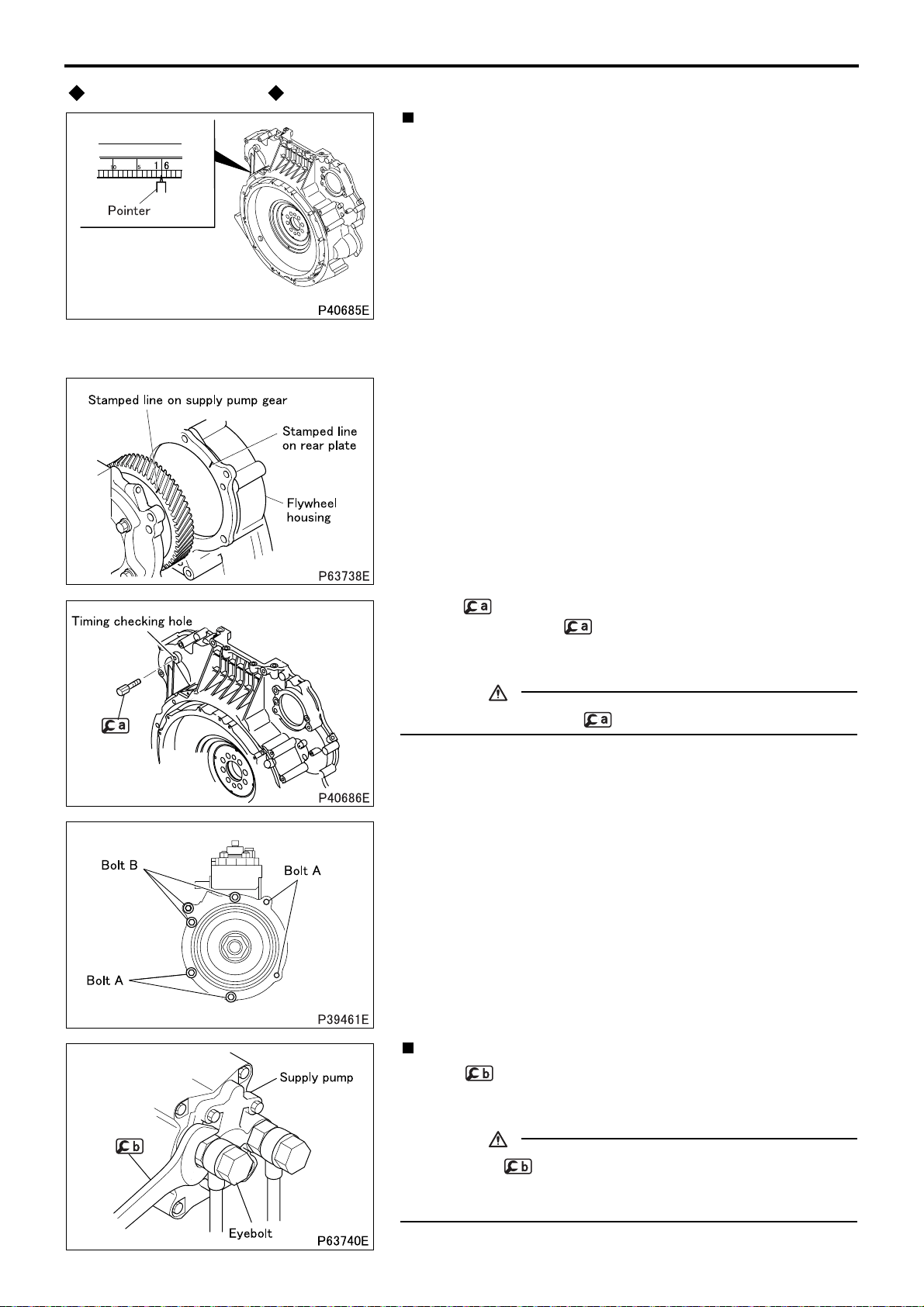
13-68
Installation procedure
Installation: Mitsubishi 6M70 Fuel Supply pump
• Position the No. 1 piston to the top dead center in the compres-
sion stroke in the following manner.
• Crank the engine to align the pointer with the “1 6” mark on
the flywheel.
• This will bring either the No. 1 piston or the No. 6 piston to the
top dead center in the compression stroke. If both the inlet
and exhaust rockers can be moved by hand by the amount of
valve clearance, that cylinder is at the top dead center in the
compression stroke. From that position, every turn of the
crankshaft will alternately bring the No.1 and No. 6 pistons to
the top dead center in the compression stroke. (See Gr11.)
• Install the supply pump while ensuring that the stamped line on
the supply pump gear is aligned with the stamped line on rear
plate.
• Insert into the timing checking hole of the flywheel housing.
• If the seat surface of is securely fitted, the timing is aligned.
If the seat surface lifts, the gears are not properly engaged. Re-
install the supply pump.
CAUTION
• Remember to remove after it is used.
• Install bolt A from the supply pump side and bolt B from the fly-
wheel housing side.
Installation: Fuel suction pipe and fuel feed pipe
• Apply (width across flats: 24 mm) to the connector of the
supply pump as a stopper, and then tighten the eyebolt to install
the fuel suction pipe and fuel feed pipe.
CAUTION
• Do not use except for a stopper of the fuel suction pipe
and fuel feed pipe, otherwise the open end section may be
broken.
SUPPLY PUMP
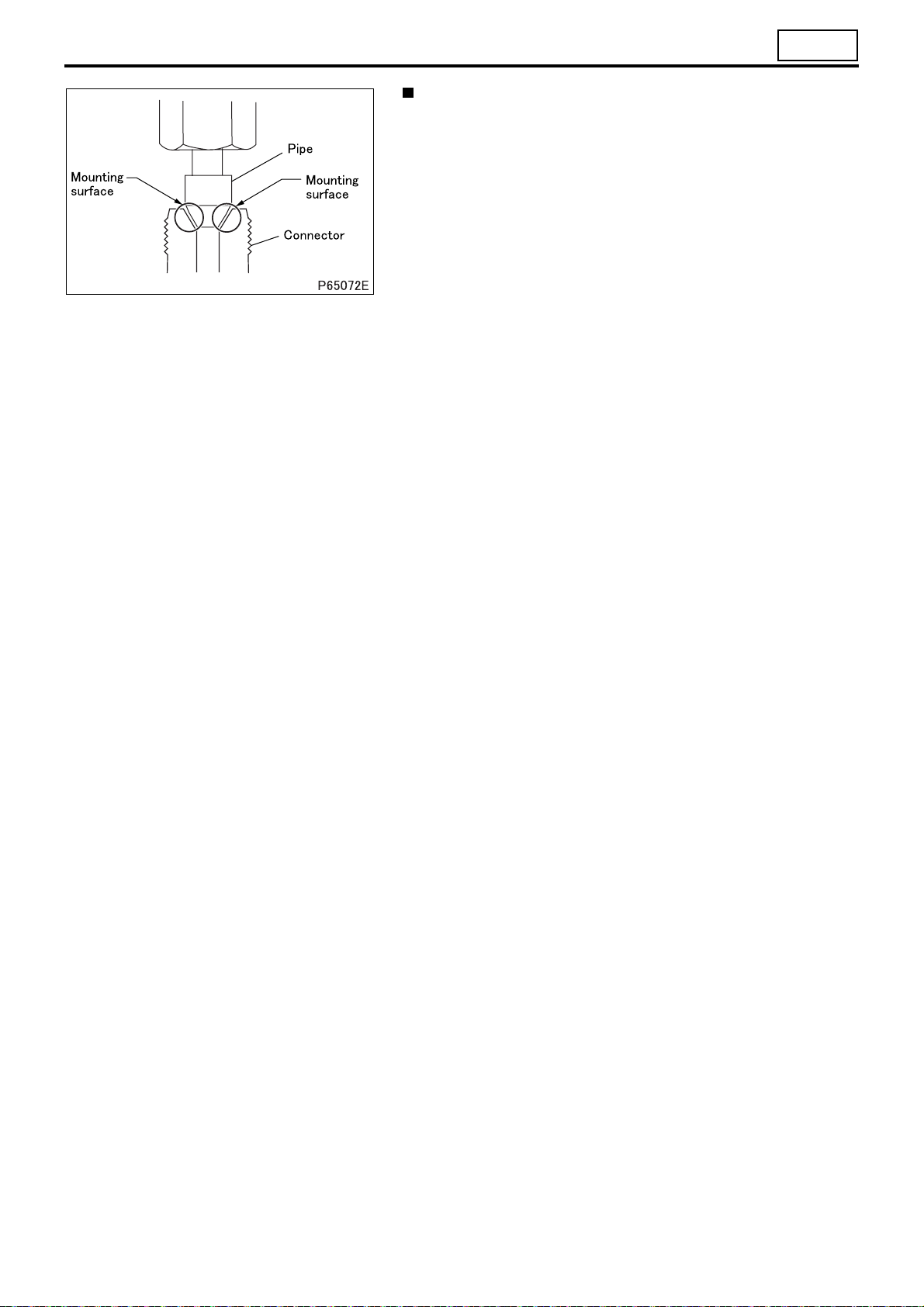
13
13-69
Installation: Fuel pipe
• Ensure that the pipe and mounting surfaces of the connector are
flat and free from damage.
• Bring the pipe into intimate contact with mounting surfaces of the
connector evenly, and temporarily tighten it without applying an
excessive force.
• Tighten it to the specified torque after temporary tightening.
Mitsubishi 6M70 Engine Parts contact:
email: [email protected]
Phone: 269 673 1638
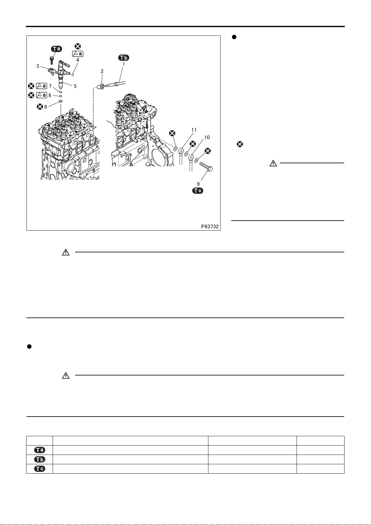
13-70
Removal sequence
1 Injection pipe
2 Injection pipe seal
3 Nozzle bridge
4 O-ring
5 Injector
6 O-ring
7 O-ring
8 Nozzle tip gasket
9 Eyebolt
10 Fuel return pipe
11 Fuel return pipe
: Non-reusable parts
WARNING
• Fuel is highly flammable.
Do not handle it near flames or
heat.
• Spilled fuel may catch fire and
therefore, must be wiped off com-
pletely.
CAUTION
• The harnesses and connectors between the injectors and common rail electronic control unit are under
high voltage. Be careful not to receive an electric shock. Before attempting to remove the injectors, turn
the starter switch to the LOCK position.
• Carefully handle the injector, taking care not to damage the threaded portion and nozzle as high pressure
is applied to the injector.
• To eliminate fuel injection and other problems, protect the injectors and pipes, that have been removed,
from the ingress of contaminants.
• Contact Bosch Service Station for any service needs of the injector.
Installation sequence
Follow the removal sequence in reverse.
CAUTION
• Do not attempt to clean the nozzle hole with a wire brush or other similar tools, or the hole can be dam-
aged.
• Be sure to tighten the nozzle bridge bolts to the specified torque. Overtightening the bolts can deform the
injectors, resulting in incorrect fuel injection.
Tightening torque (Unit: N·m {kgf·m})
Mark Parts to be tightened Tightening torque Remarks
Bolt (nozzle bridge mounting)
54 nm {5.5 kgfm} 40 Ft Lbs
–
Mitsubishi 6M70 Injection pipe 29 to 34 {3.0 to 3.5} –
Eyebolt (fuel return pipe mounting) 40 {4} –
MITSUBISHI 6M70 INJECTOR
M
its
ubishi 6M70 Engine Parts contact:
email: [email protected]
Phone: 269 673 1638
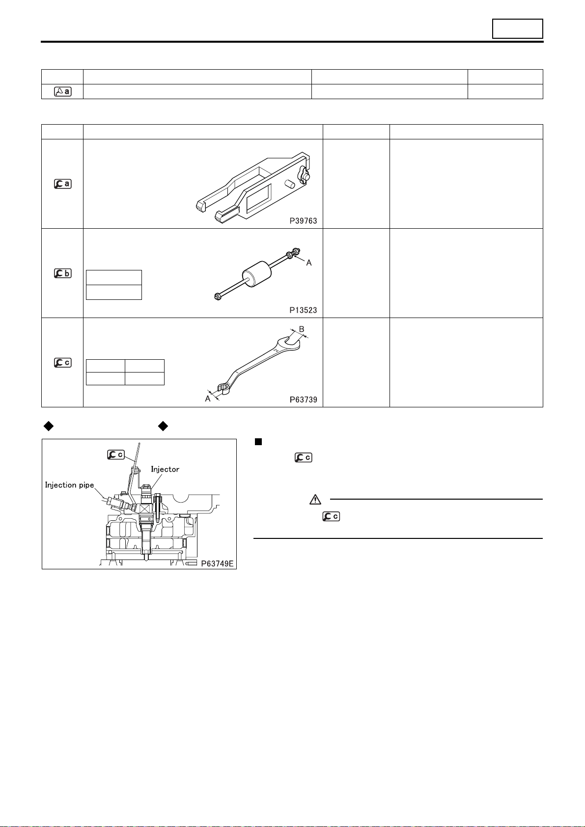
13
13-71
Lubricant and/or sealant
Special tools (Unit: mm)
Removal procedure
•
Removal: Mitsubishi 6M70 Injection pipe
Apply (width across flats
: 15 mm) to the connector of the
injector as a stopper, and then loosen the union nut to remove
the injection pipe.
CAUTION
• Do not use except for a stopper of the injection pipe,
otherwise the open end section may be broken.
Mark Points of application Specified lubricant and/or sealant Quantity
O-ring Engine oil As required
Mark Tool name and shape Part No. Application
ME165088
Removing injector
(use with MH061071)
MH061071 Removing injector
ME355665
Removal and installation of injection
pipe
Injector extractor
adapter
Nozzle extractor
A
M8 × 1.25
Open end spanner
AB
15 24
Mitsubishi 6M70 Engine Parts contact:
email: [email protected]
P
hone: 269 673 1638
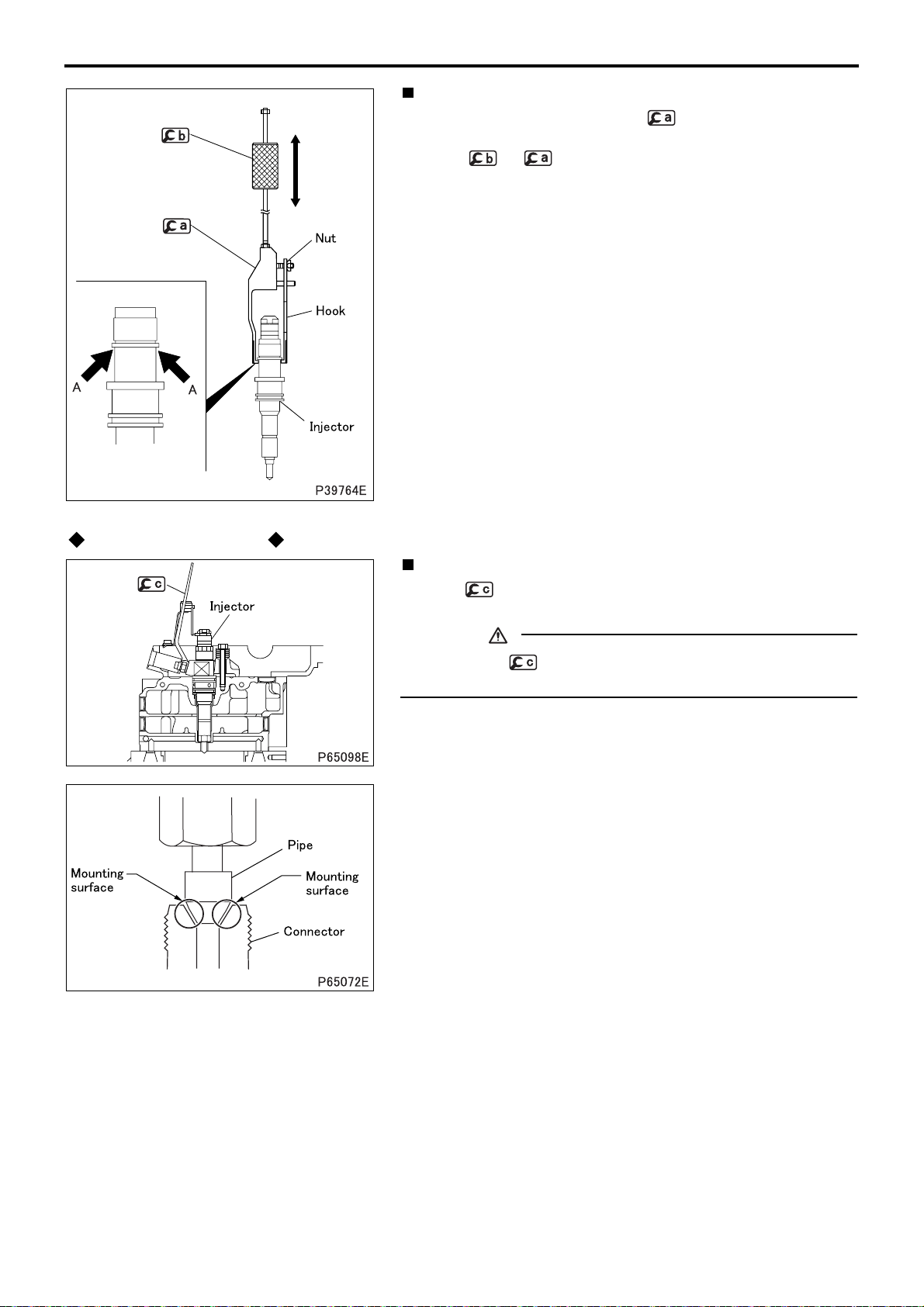
13-72
Removal: Mitsubishi 6M70 Injector
• Tighten the nut so that a hook of can be hung on section A
of the injector.
• Attach to and remove the injector.
Installation procedure
•
Installation: Mitsubishi 6M70 Injection pipe
Apply (width across flats
: 24 mm) to the connector of the
injector as a stopper.
CAUTION
• Do not use except for a stopper of the injection pipe,
otherwise the open end section may be broken.
• Ensure that the pipe and mounting surfaces of the connector are
flat and free from damage.
• Bring the pipe into intimate contact with mounting surfaces of the
connector evenly, and temporarily tighten it without applying an
excessive force.
• Tighten it to the specified torque after temporary tightening.
INJECTOR

M E M O
13-73
13
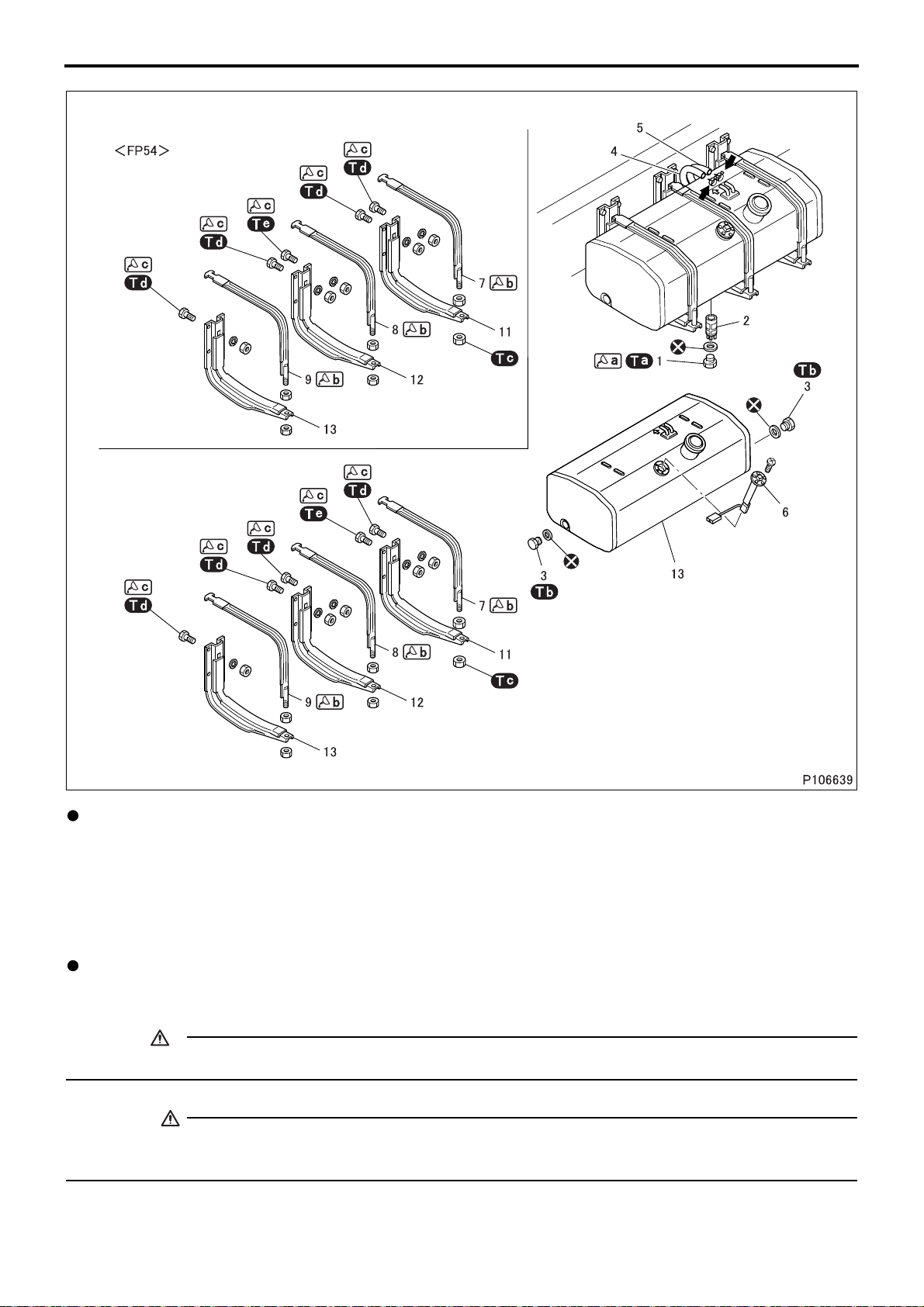
13-74
Removal sequence
Installation sequence
Follow the removal sequence in reverse.
DANGER
• Do not allow any flames or sources of heat near the fuel tank, as it may explode.
WARNING
• Fuel is highly flammable. Keep it away from flames and sources of heat.
• Thoroughly wipe up any spilled fuel, otherwise it may catch fire.
1 Drain plug
2 Strainer
3 Connecting plug
4 Suction hose
5 Return hose
6 Fuel level sensor
7 Fuel tank strap
8 Fuel tank strap
<Except FV51>
9 Fuel tank strap
10 Fuel tank
11 Fuel tank bracket
12 Fuel tank bracket
<Except FV51>
13 Fuel tank bracket
FUEL TANK
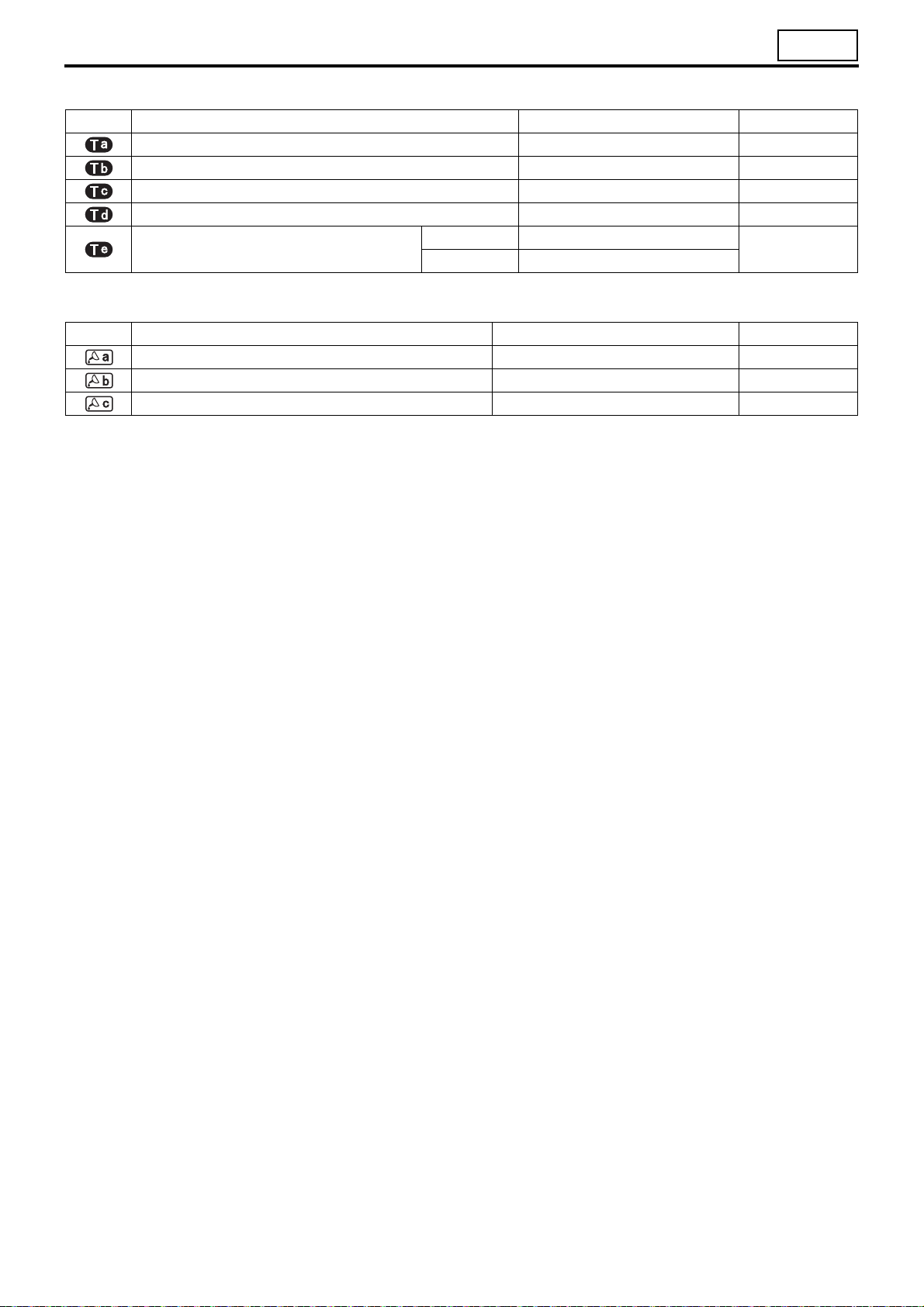
13
13-75
Tightening torque (Unit: N·m {kgf·m})
Lubricant and/or sealant
Mark Parts to be tightened Tightening torque Remarks
Drain plug 127 {13} –
Connecting plug 20 {2.0} –
Nut (fuel tank strap mounting) 11.7 to 12.7 {1.2 to 1.3} –
Bolt (fuel tank bracket mounting) 54 to 72 {5.5 to 7.3} Wet
Bolt (fuel tank bracket mounting)
FV51 54 to 72 {5.5 to 7.3}
Wet
Except FV51 150 to 204 {15 to 21}
Location Points of application Specified lubricant and/or sealant Quantity
Seat surface of drain plug Seal end No. 22 As required
Contact area between fuel tank strap and fuel tank Soapy water As required
Thread area of bolt Engine oil As required
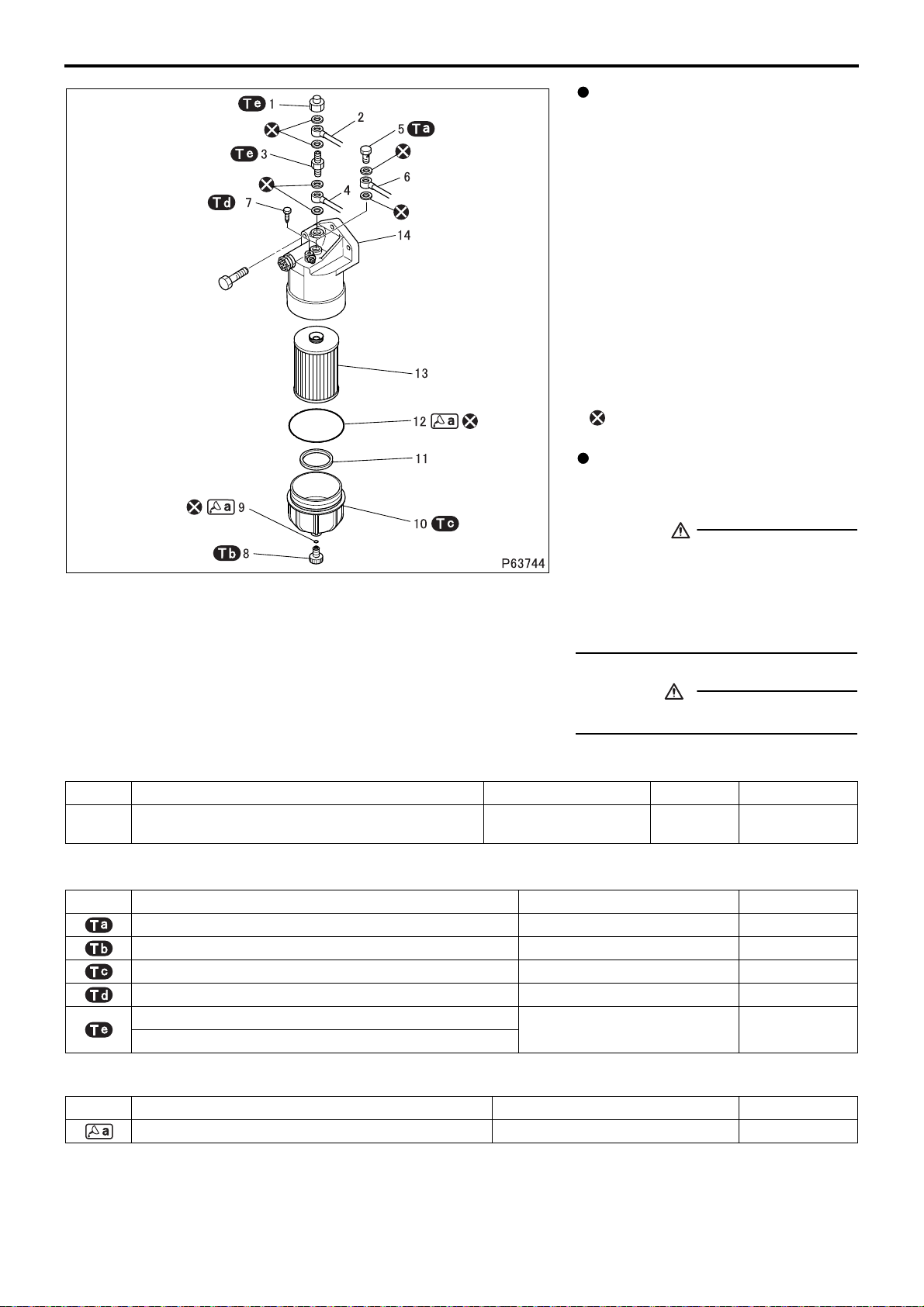
13-76
Disassembly sequence
1 Cap
2 Fuel return pipe
3 Overflow valve
4 Fuel feed pipe
5 Eyebolt
6 Fuel feed pipe
7 Plug
8 Drain plug
9 O-ring
10 Case
11 Float
12 O-ring
13 Element
14 Fuel filter head
: Non-reusable parts
Assembly sequence
Follow the disassembly sequence in re-
verse.
WARNING
• Fuel is highly flammable. Keep it
away from flames and sources of
heat.
• Thoroughly wipe up any spilled fu-
el. Otherwise, it may catch fire.
CAUTION
• Be careful not to damage the case.
Service standards
Tightening torque (Unit: N·m {kgf·m})
Lubricant and/or sealant
Location Maintenance item Standard value Limit Remedy
3 Overflow valve
1.14 ± 0.03 MPa
{12 ± 0.3 kgf/cm
2
}
–Replace
Mark Parts to be tightened Tightening torque Remarks
Eyebolt 30 {3.0} –
Drain plug 2 ± 0.5 {0.2 ± 0.05} –
Case 18 to 20 {1.8 to 2.0} –
Plug 9.8 ± 2.0 {1.0 ± 0.2} –
Overflow valve
20 to 29 {2.0 to 3.0} –
Cap
Mark Points of application Specified lubricant and/or sealant Quantity
O-ring Engine oil As required
FUEL FILTER
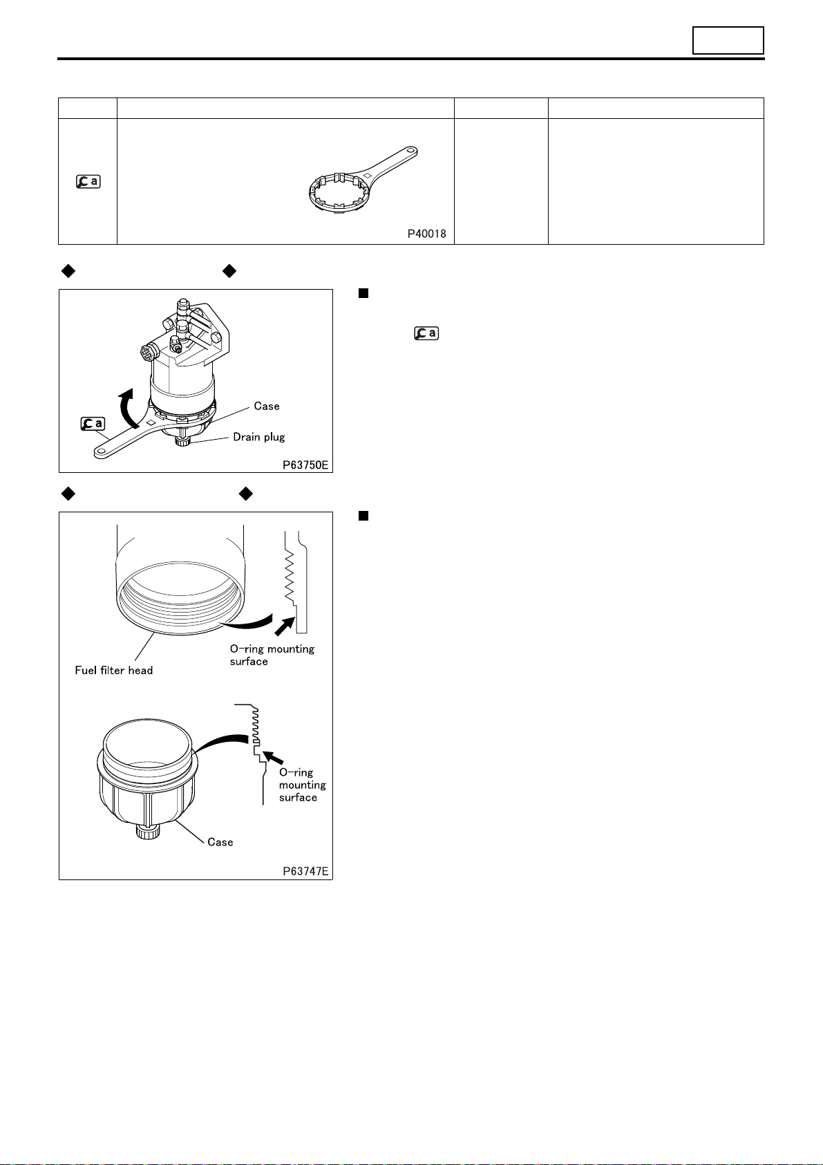
13
13-77
Special tools
Removal procedure
Removal: Case
• Drain fuel from the case by loosening the drain plug.
• Us
ing
, remove the case.
Installation procedure
Installation: Case
• Clean the surface of the fuel filter head and case where the O-
ring is to be mounted.
Mark Tool name and shape Part No. Application
Filter wrench MH063201 Removal and installation of case
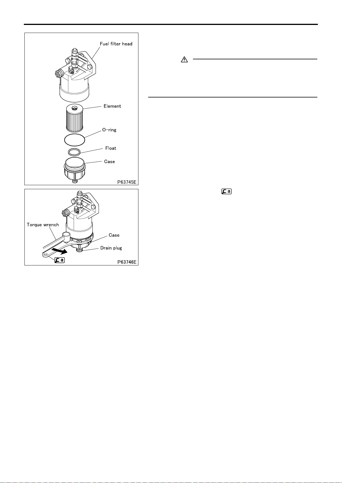
13-78
• Replace the filter element and O-rings with new parts.
• Apply a thin coat of engine oil to the O-rings. Install the O-rings
onto the case.
CAUTION
• The use of non-genuine filter elements will lead to engine
problems. Be sure to use only genuine parts.
• To help prevent fuel injection problems, keep the fuel filter
and hoses free from contamination.
• Install a torque wrench to and tighten the case to the spec-
ified torque.
• Tighten the drain plug to the specified torque. With the plug cor-
rectly installed, bleed air from the fuel system.
• Start the engine and check that there is no fuel leakage.
• If there is fuel leakage, remove and install the fuel filter correctly.
FUEL FILTER

M E M O
13-79
13
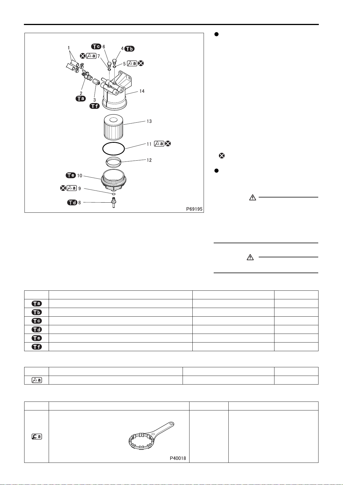
13-80
Disassembly sequence
1 Fuel hose
2 Fuel cut valve
3 Connector
4 Plug A
5 O-ring
6 Plug B
7 O-ring
8 Drain plug
9 O-ring
10 Cover
11 O-ring
12 Float
13 Element
14 Body
: Non-reusable parts
Assembly sequence
Follow the disassembly sequence in re-
verse.
WARNING
• Fuel is highly flammable. Keep it
away from flames and sources of
heat.
• Thoroughly wipe up any spilled fu-
el. Otherwise, it may catch fire.
CAUTION
• Be careful not to damage the case.
Tightening torque (Unit: N·m {kgf·m})
Lubricant and/or sealant
Special tools
Mark Parts to be tightened Tightening torque Remarks
Fuel cut valve 35 {3.6} –
Plug A 12.3 ± 2.5 {1.3 ± 0.3} –
Plug B 17.2 ± 2.5 {1.8 ± 0.3} –
Drain plug 1.47 ± 0.3 {0.15 ± 0.03} –
Cover 19.6 ± 2.5 {2.0 ± 0.25} –
Connector 40 {4.0} –
Mark Points of application Specified lubricant and/or sealant Quantity
O-ring Engine oil As required
Mark Tool name and shape Part No. Application
Filter wrench MH063201 Removal and installation of cover
WATER SEPARATOR
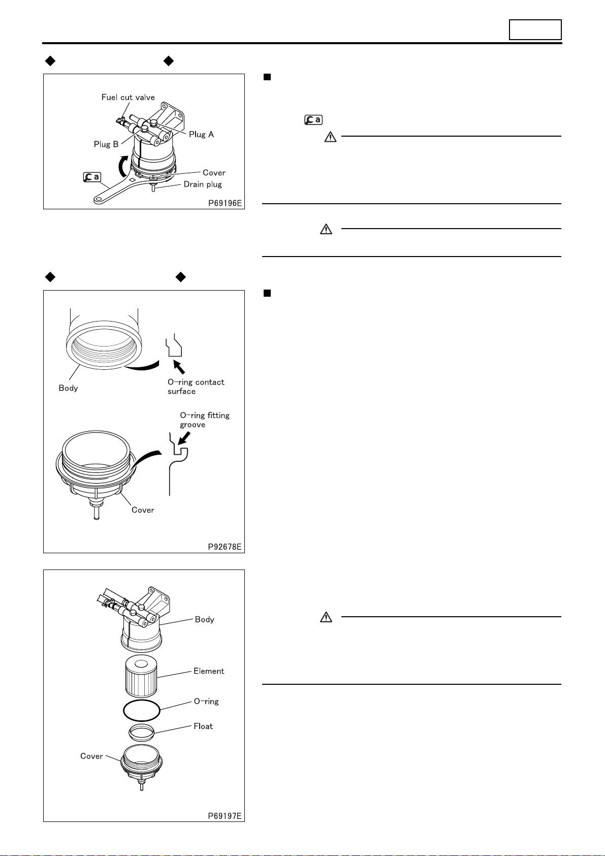
13
13-81
Removal procedure
Removal: Cover
• Loosen plugs A and B and then loosen the drain plug. Next, dis-
charge fuel from the water separator.
• Using , remove the cover.
WARNING
• Do not bring an open flame or heat near to fuel, which can
catch fire easily.
• Thoroughly wipe the surface clean of spilled fuel that could
otherwise lead to a fire.
CAUTION
• Use care not to damage the cover.
Installation procedure
Installation: Cover
• Clean the surface of the water separator body, against which O-
ring abuts, and the O-ring groove in the cover.
• Replace the filter element and O-ring with new parts.
• Apply a thin coat of engine oil to the O-ring. Install the O-ring
onto the case.
CAUTION
• The use of non-genuine filter elements will lead to engine
problems. Be sure to use only genuine parts.
• To help prevent fuel injection problems, keep the water sep-
arator and fuel hoses free from contamination.
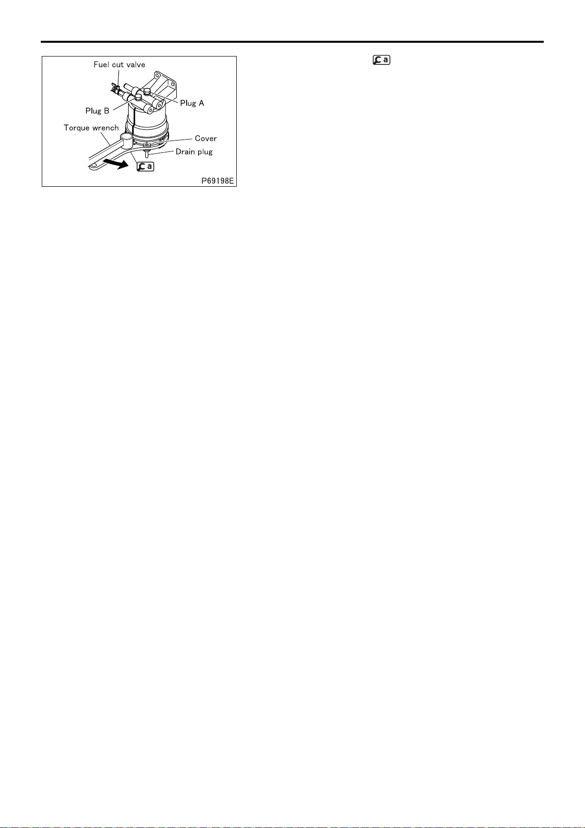
13-82
• Install torque wrench to and tighten the case to the speci-
fied torque.
• Tighten the drain plug and plugs A, B to the specified torque.
With the plug correctly installed, bleed air from the fuel system.
• Start the engine and ensure that there is no fuel leakage.
• If there is fuel leakage, remove and install the water separator
correctly.
WATER SEPARATOR

M E M O
13-83
13
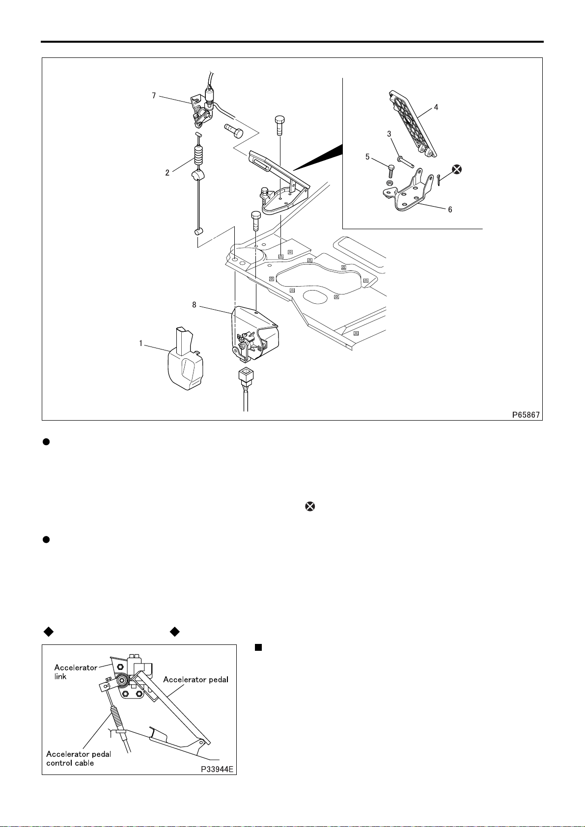
13-84
Removal sequence
Installation sequence
Follow the removal sequence in reverse.
• After the installation, check the no-load minimum speed and no-load maximum speed for normal state and adjust
them if required. (See “ON-VEHICLE INSPECTION AND ADJUSTMENT”.)
• Make sure that the accelerator pedal moves smoothly.
Installation procedure
Installation: Accelerator pedal control cable
• Connect the accelerator pedal control cable to the accelerator
link.
1 Cover
2 Accelerator pedal control cable
3 Accelerator pedal pin
4 Accelerator pedal
5 Stopper bolt
6 Accelerator pedal bracket
7 Accelerator link (See later section.)
8 Accelerator pedal position sensor
: Non-reusable parts
ENGINE CONTROL
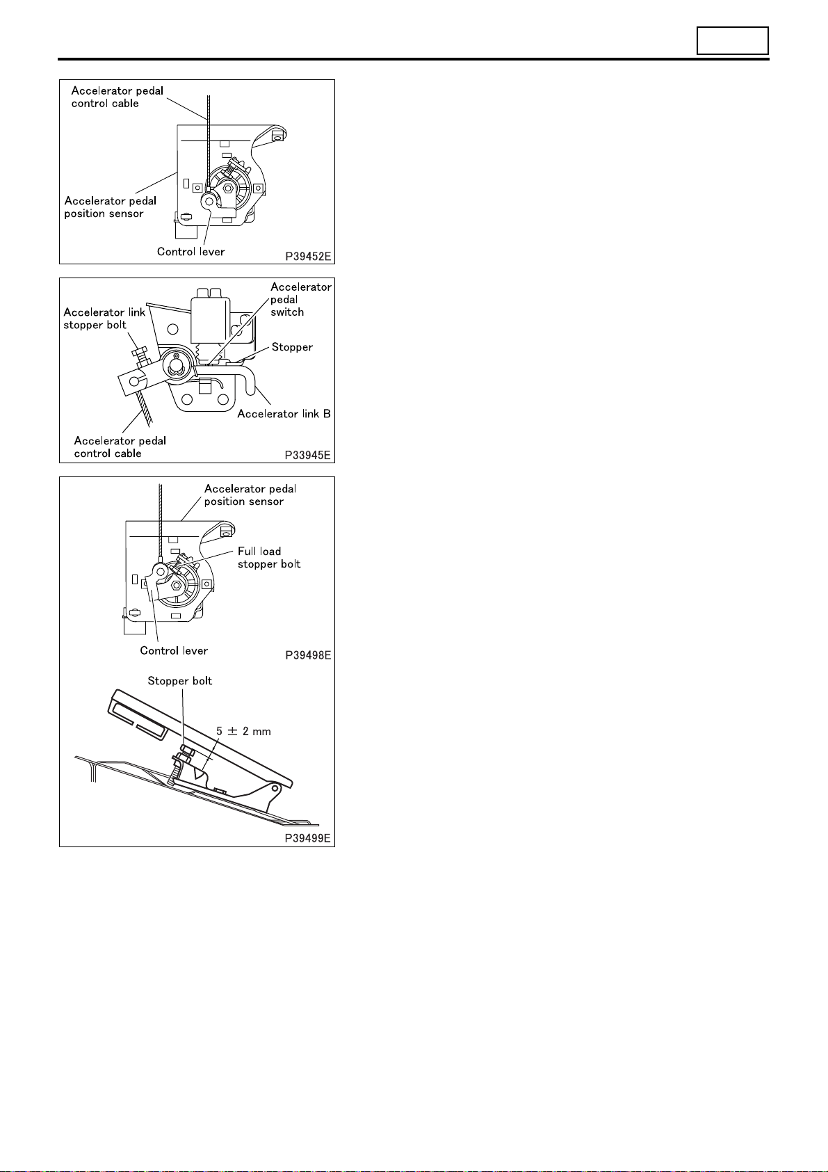
13
13-85
• Install the other end of the accelerator pedal control cable onto
the accelerator position sensor control lever.
• Adjust tension of the accelerator pedal control cable with the ac-
celerator link stopper bolt so that accelerator link B contacts the
stopper.
• Press the accelerator pedal until the control lever of the acceler-
ator pedal position sensor contacts the full load stopper bolt.
• Adjust the stopper bolt so that clearance between the accelera-
tor pedal and stopper bolt is to the dimension shown in the illus-
tration.
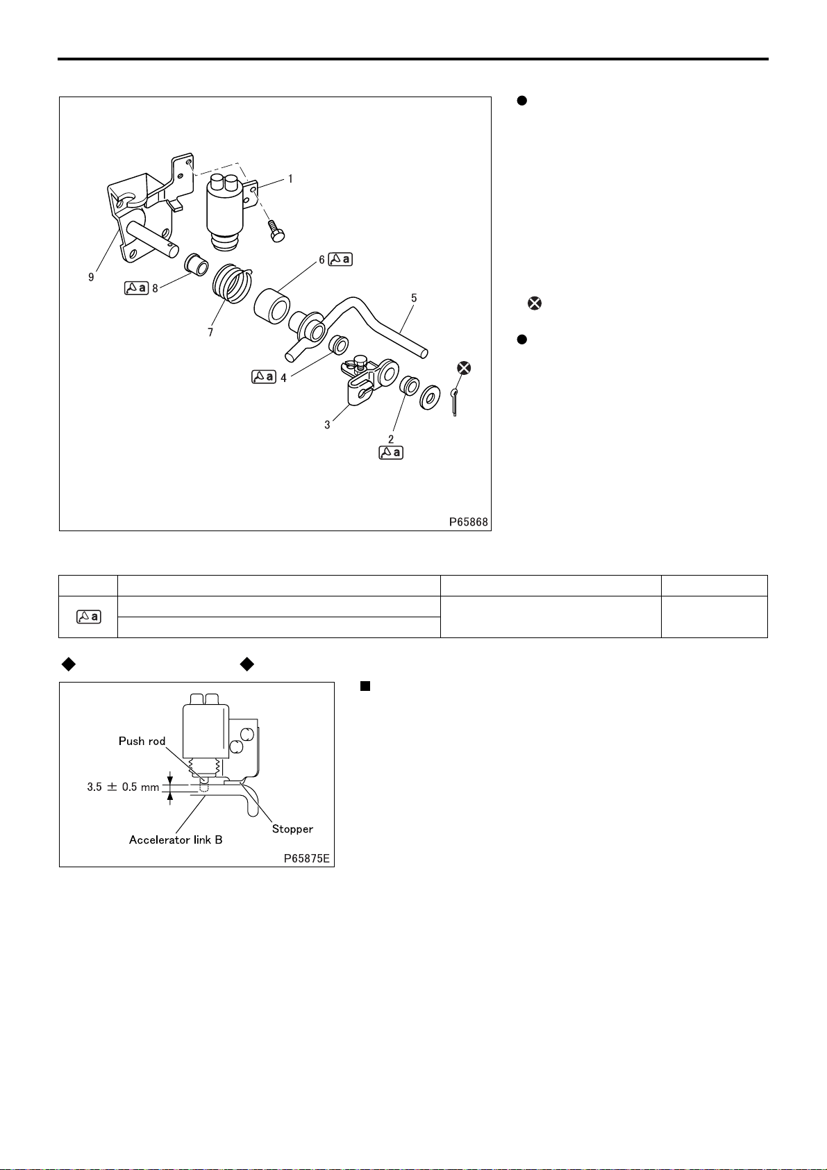
13-86
Accelerator Link
Removal sequence
1 Accelerator pedal switch
2 Bushing
3 Accelerator link A
4 Bushing
5 Accelerator link B
6 Collar
7 Return spring
8 Bushing
9 Accelerator link bracket
: Non-reusable parts
Installation sequence
Follow the removal sequence in reverse.
Lubricant and/or sealant
Installation procedure
Installation: Accelerator pedal switch
• Place accelerator link B against the stopper.
• Place the push rod of the accelerator pedal switch against accel-
erator link B and install the accelerator pedal switch so that the
stroke of the push rod is to the dimension shown in the illustra-
tion.
Mark Points of application Specified lubricant and/or sealant Quantity
Sliding surfaces of bushing and accelerator link bracket
Chassis grease
[NLGI No. 1 (Li soap)]
As required
Sliding surfaces of collar and return spring
ENGINE CONTROL

M E M O
13-87
13
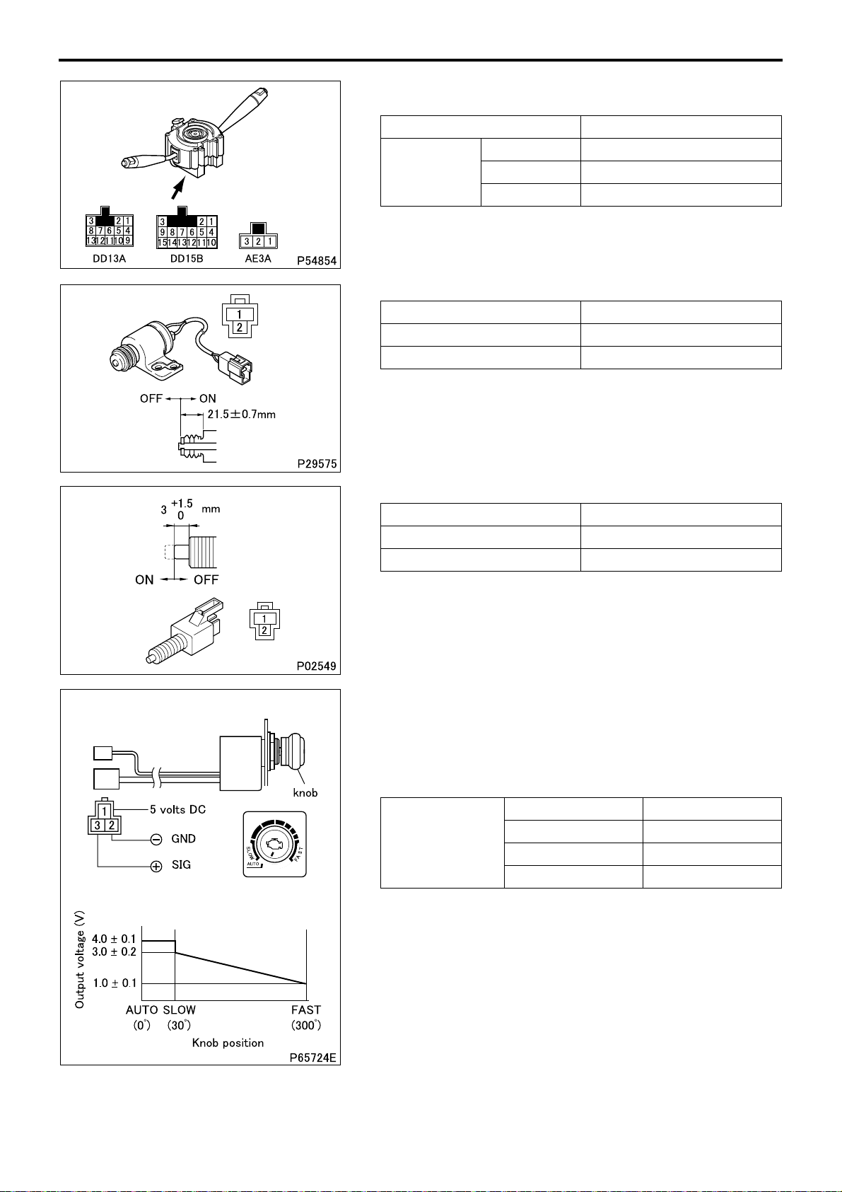
13-88
#001 Inspection of combination switch
DD15B connector connection table
• For other inspections than shown above, see Gr54.
• If there is any abnormality, replace the switch.
#029 Inspection of accelerator pedal switch
• If there is any abnormality, replace the switch.
#031 Inspection of clutch switch
• If there is any abnormality, replace the switch.
#157 Inspection of idling speed adjustment potentiometer
• Apply 5 volts DC to terminals 1 and 2 of the idling speed adjust-
ment potentiometer.
• Turn the knob fully counterclockwise. Then, measure the output
voltage across terminals 2 and 3 (see the diagrams on the left)
while slowly turning the knob clockwise.
• If any measurement is out of specification, replace the idling
speed adjustment potentiometer.
Switch position Terminals with continuity
Powertard
switch
OFF –
1st step 6 – 11
2nd step 6 – 11, 3 – 9
Switch position Terminals with continuity
OFF –
ON 1 – 2
Switch position Terminals with continuity
OFF –
ON 1 – 2
Standard value
Knob position Output voltage
AUTO (0°) 4.0 ± 0.1 V
SLOW (30°) 3.0 ± 0.2 V
FAST (300°) 1.0 ± 0.1 V
INS
PECTION OF MITSUBISHI 6M70 ELECTRICAL PARTS
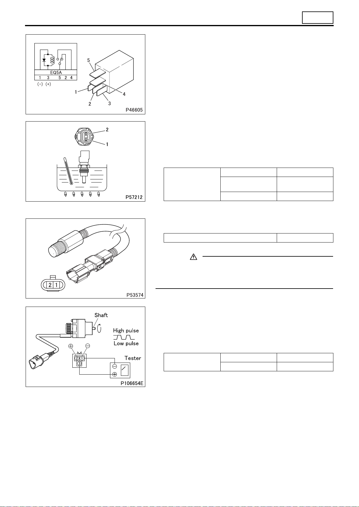
13
13-89
#201 Inspection of relay (normally open 5-pin)
• Check continuity and operating condition of the relay. Replace
the relay if necessary.
#262 Inspection of Mitsubishi 6M70 water temperature sensor
• Place the water temperature sensor in a container filled with en-
gine oil.
• Heat the oil to each of the specified temperatures. Stir the oil
well while doing so.
• Measure the resistance between terminals 1 and 2.
• If either measurement is out of specification, replace the sensor.
#263 Inspection of Mitsubishi 6M70 engine speed sensor
• Measure the resistance between terminals 1 and 2.
• If the measurement is out of specification, replace the sensor.
CAUTION
• The signal may not output if the sensor tightening torque is
insufficient. Check if the sensor is tightened with the cor-
rect tightening torque. (See Gr11.)
#265 Inspection of vehicle speed sensor
• With the 24 volts DC applied to terminals 1 and 2, slowly turn the
shaft of the vehicle speed sensor.
• Measure the maximum voltage (high pulse voltage) and mini-
mum voltage (low pulse voltage) occurring at each specified pair
of terminals.
• If any measurement is out of specification, replace the sensor.
Standard value
20°C 2.45 ± 0.14 kΩ
80°C
0.32 kΩ
(reference value)
110°C147.1 ± 2 Ω
Standard value (at 25°C) 2.2 ± 0.2 kΩ
Standard value
Low pulse voltage 0.5 V or lower
High pulse voltage 8 ± 1 V
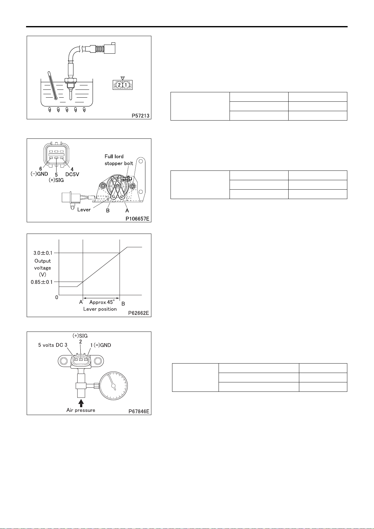
13-90
#305 Inspection of Misubishi 6M70 intake air temperature sensor
• The intake air temperature sensor 1 may output false signals if
its tip is contaminated. Clean it if necessary. (See Gr15.)
• Place the sensor in a container filled with engine oil.
• Heat the oil to each of the specified temperatures. Stir the oil
well while doing so.
• Measure the resistance between terminals 1 and 2.
• If either measurement is out of specification, replace the sensor.
#317 Inspection of power take-off load sensor
• Apply 5 volts DC to terminals 4 and 6.
• Measure the output voltage across terminals 5 and 6 with the le-
ver at idling position A and at full-load position B.
• If measurement of full-load position B deviates from standard
value, adjust with full load stopper bolt.
• If measurement of idling position A deviates from standard val-
ue, replace the sensor.
#318 Inspection of Mitsubishi 6M70 boost pressure sensor
• Apply 5 volts DC to terminals 3 and 1.
• Apply air pressure. Gradually increase it and, while doing so,
measure the output voltage occurring at terminals 2 and 1.
• If any measurement is out of specification, replace the sensor.
#319 Inspection of Mitsubishi 6M70 common rail pressure sensor
• The sensor cannot easily be inspected in isolation, so you must
evaluate it indirectly by inspection of system harnesses and re-
lated parts.
• If there is no abnormality in any related part but the system is ab-
normal, replace the common rail.
Standard value
0°C15 kΩ
20°C6.514 kΩ
80°C 0.874 kΩ
Standard value
Lever position Output voltage
Idling position A 0.85 ± 0.1 V
Full-load position B 3.0 ± 0.1 V
Standard value
Air pressure (gauge pressure) Voltage
99 kPa {1.0 kg/cm
2
} Approx. 2.5 V
232.2 kPa {2.3 kg/cm
2
} Approx. 4.5 V
+3.78
–2.94
+1.437
–1.147
+0.136
–0.115
INSPECTION OF ELECTRICAL EQUIPMENT
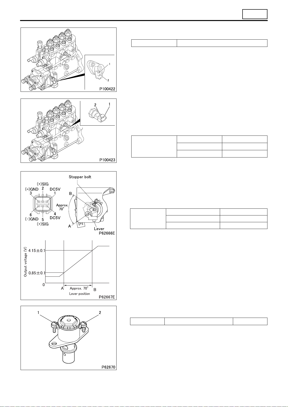
13
13-91
#320 Inspection of Mitsubishi 6M70 cylinder recognition sensor
• Measure the resistance between terminals 1 and 2.
• If the measurement is out of specification, replace the sensor.
#323 Inspection of Mitsubishi 6M70 fuel temperature sensor
• Place the fuel temperature sensor in a container filled with en-
gine oil.
• Heat the oil to each of the specified temperatures. Stir the oil
well while doing so.
• Measure the resistance between terminals 1 and 2.
• If any measurement is out of specification, replace the sensor.
#324 Inspection of accelerator pedal position sensor
• Apply 5 volts DC to terminals 4 and 6 and terminals 1 and 3 of
the accelerator pedal position sensor connector.
• Measure the output voltage at terminals 5 and 6 (sensor 1) and
the output voltage at terminals 2 and 3 (sensor 2) with the lever
in each specified position.
A: Position in which accelerator pedal switch is fully pushed in
by lever
B: Position in which lever is touching stopper bolt
• If any output voltage is out of specification, make an adjustment.
• If any output voltage is still out of specification when you have
made an adjustment, replace the sensor.
#571 Inspection of Powertard solenoid valve
• Measure the resistance between terminals 1 and 2.
• If the measurement is out of specification, replace the Powertard
solenoid valve.
Standard value 860 ± 86 Ω
Standard value
20°C 2.5 ± 0.25
kΩ
80°C 0.32 ± 0.02 kΩ
110°C 0.144 ± 0.01 kΩ
Standard value
Lever position Output voltage
Idling position A 0.85 ± 0.1 V
Full load position B 4.15 ± 0.1 V
Standard value Engine oil temperature: 25°C 32.6 to 39.8 Ω
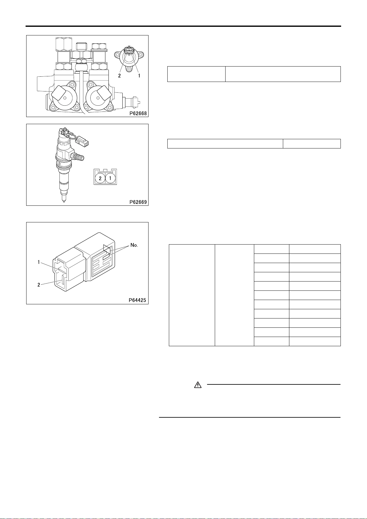
13-92
#574 Inspection of MPROP
(rail pressure control valve)
• Measure the resistance between terminals 1 and 2. Identify
MPROP1 and 2 by “M/P-1” and “M/P-2” labeled on the harness.
• If the measurement is out of specification, replace the supply
pump.
#582 Inspection of Mitsubishi 6M70 injector magnetic valve
• Measure the resistance between terminals 1 and 2.
• If the measurement is out of specification, replace the injector.
#828 Inspection of fuel injection rate adjustment resistor
• Measure the resistance of the resistor number marked on the
fuel injection rate adjustment resistor.
• If the measurement is out of specification, replace the fuel injec-
tion rate adjustment resistor with one that has the same resistor
number and same specified resistance.
CAUTION
• The fuel injection rate adjustment resistor is matched to the
engine. If you replace it, be sure to replace it with one that
has the same resistor number.
Standard value
(at 20°C)
2.6 to 3.15 Ω
Standard value (at 20
to 70°C) 0.21 to 0.295 Ω
Standard value
(at 20°C)
Resistor No.
1 270 ± 13.5 Ω
2 510 ± 25.5 Ω
3 820 ± 41 Ω
4 1300 ± 65 Ω
5 2000 ± 100 Ω
6 3300 ± 165 Ω
7 5600 ± 280 Ω
8 15000 ± 750 Ω
9 390 ± 19.5 Ω
10 4300 ± 215 Ω
11 9100 ± 455 Ω
INSPECTION OF ELECTRICAL EQUIPMENT

M E M O
13-93
13
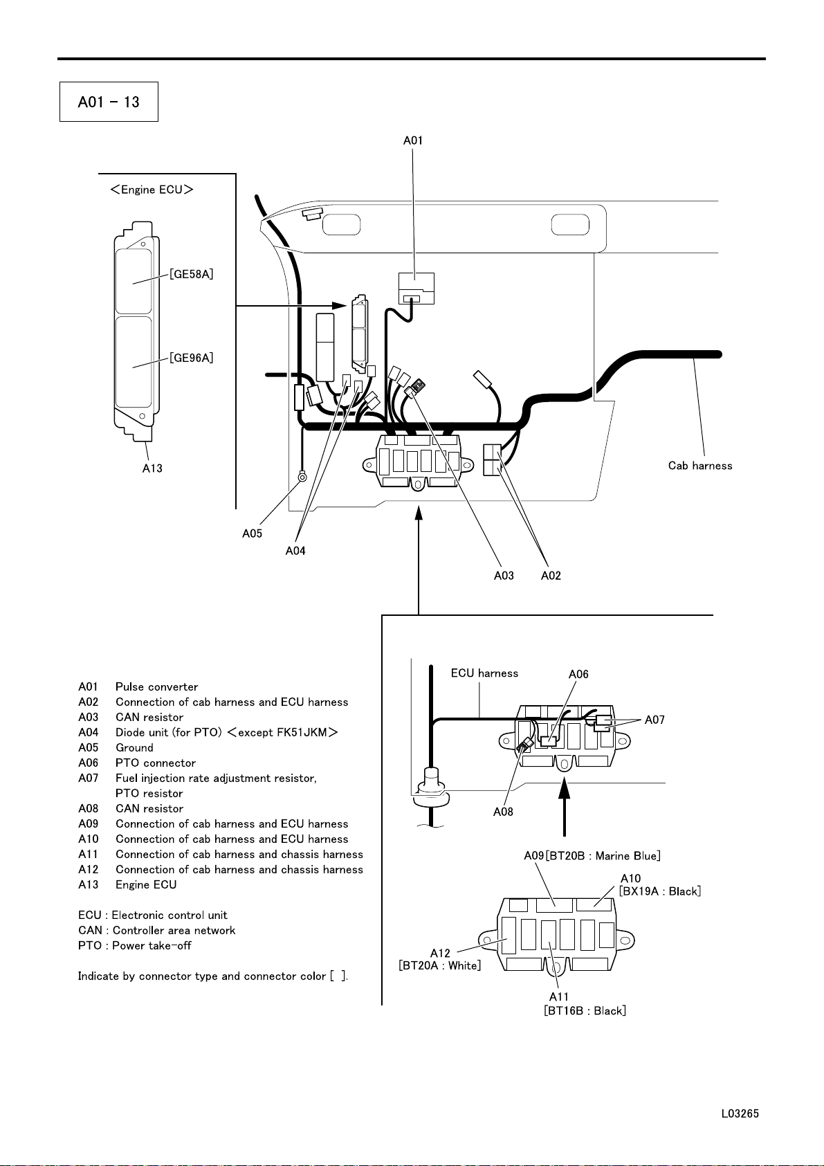
13-94
INSTALLED LOCATIONS OF PARTS
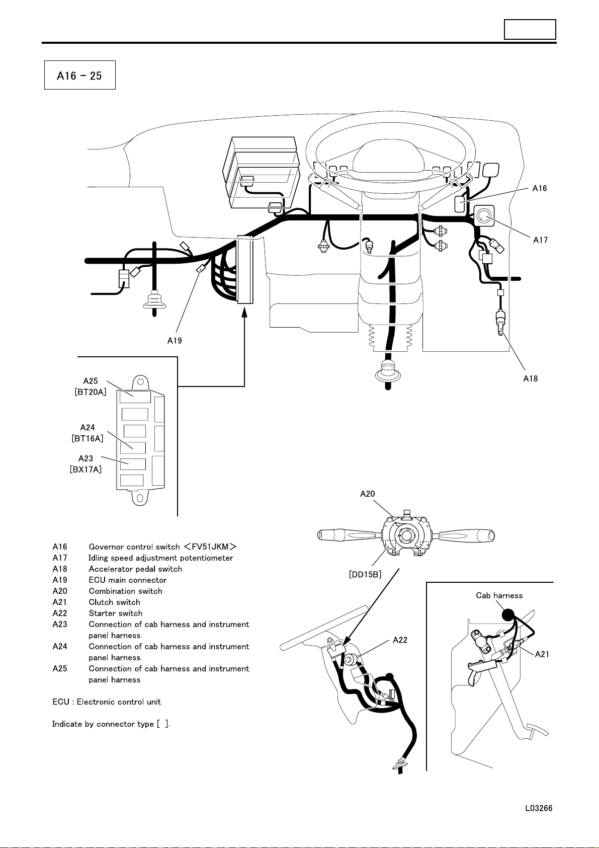
13
13-95
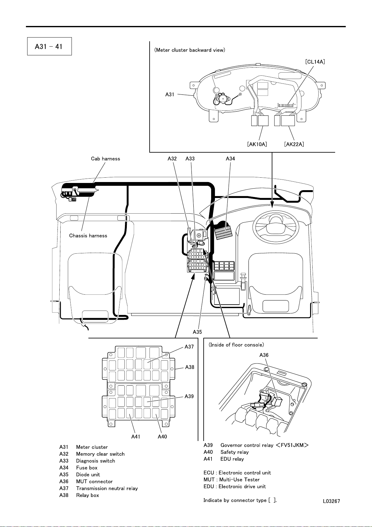
13-96
INSTALLED LOCATIONS OF PARTS

13
13-97
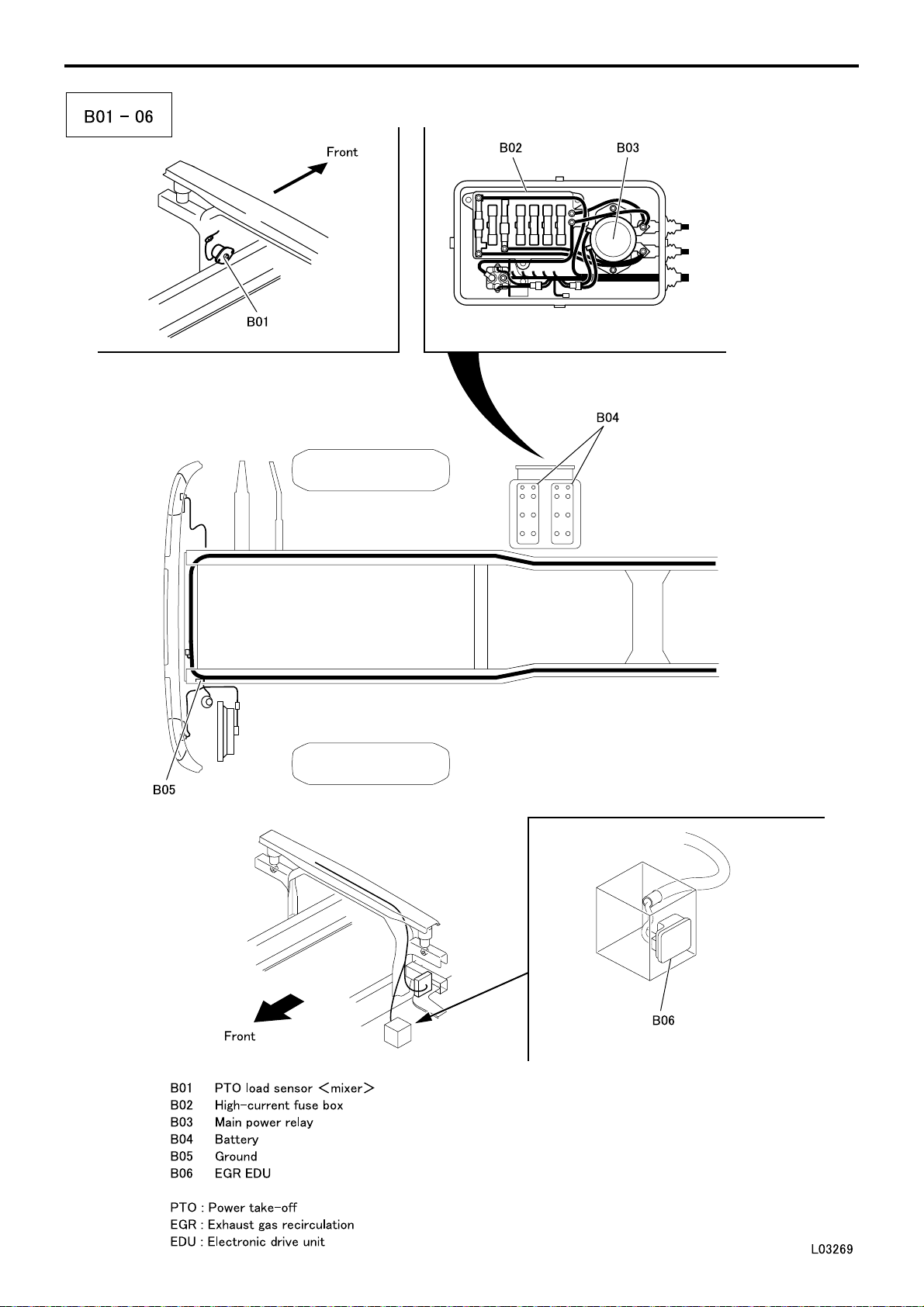
13-98
INSTALLED LOCATIONS OF PARTS
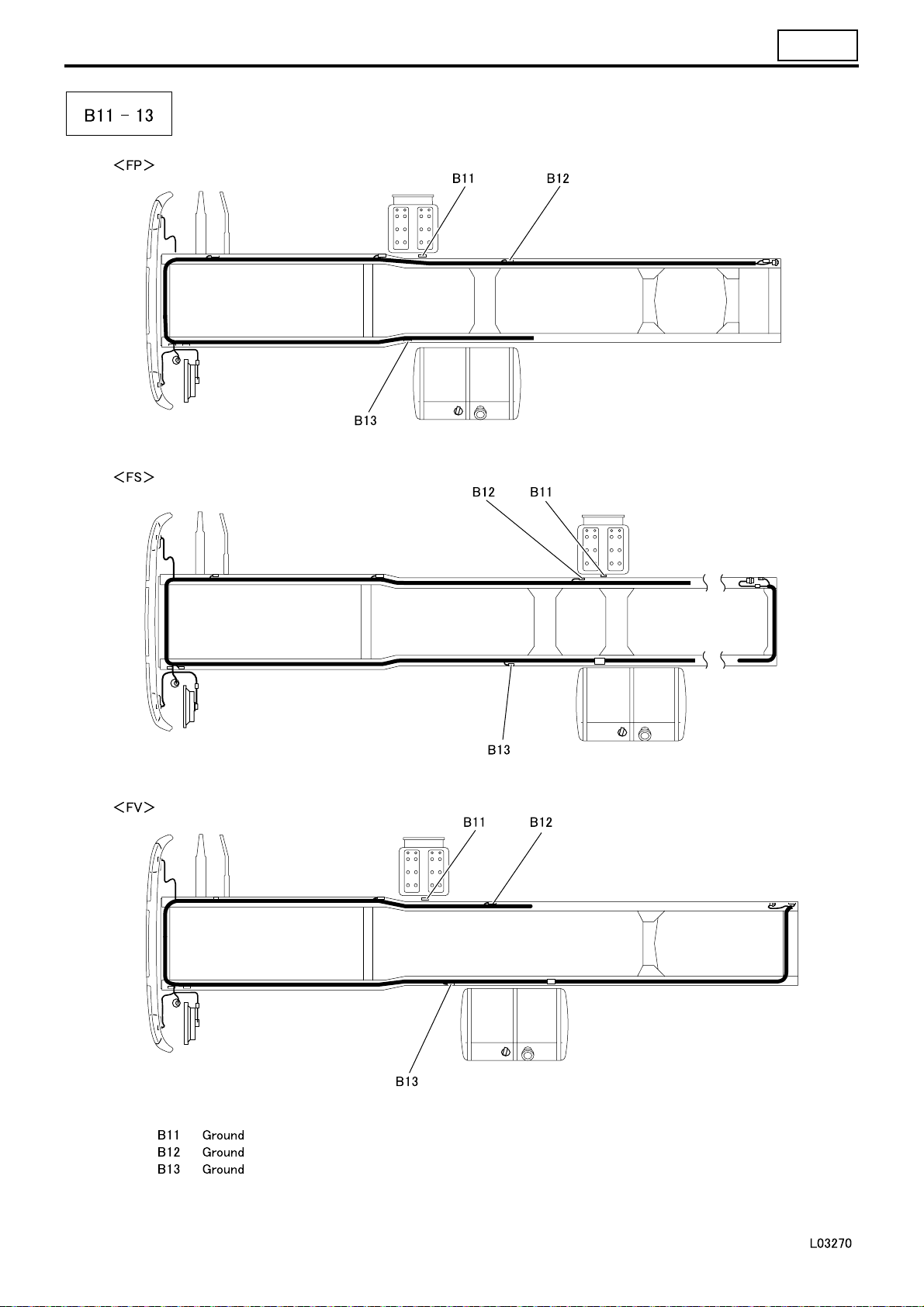
13
13-99
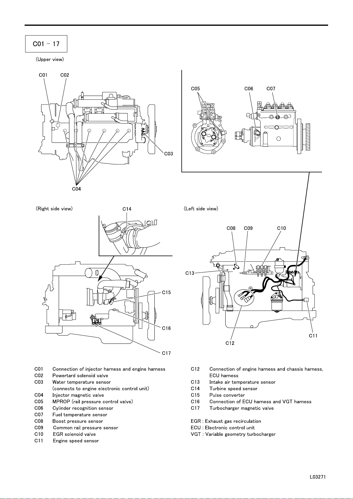
13-100
MITSUBISHI 6M70 INSTALLED LOCATIONS OF PARTS
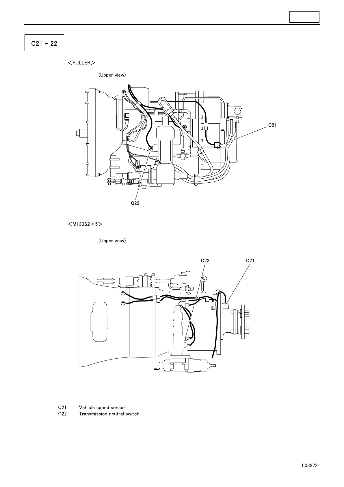
13
13-101
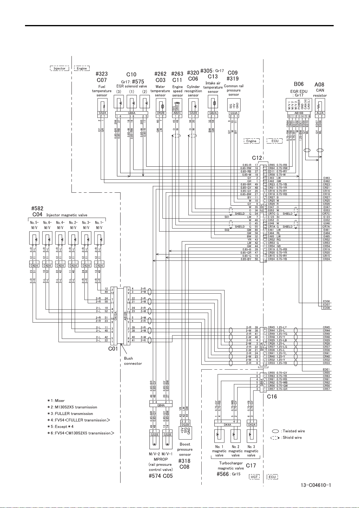
13-102
ELECTRIC CIRCUIT DIAGRAM
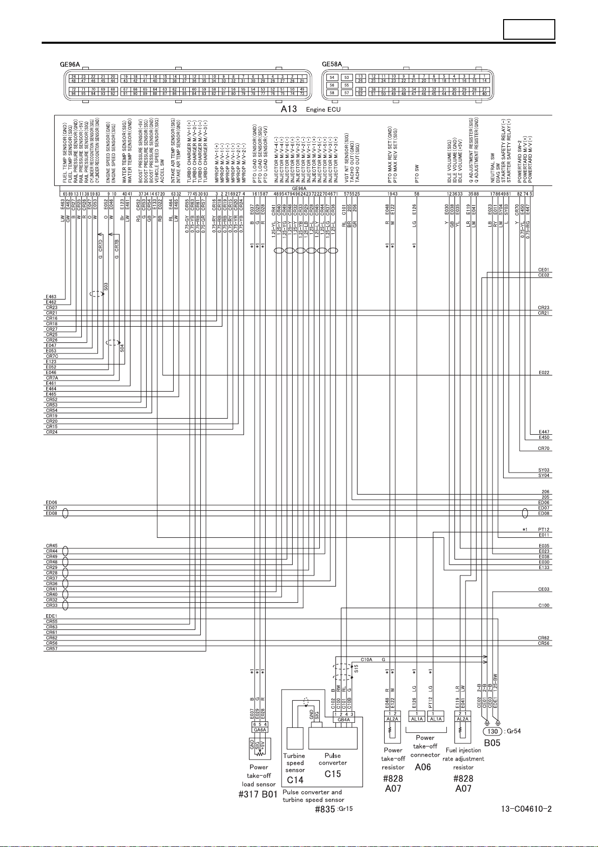
13
13-103
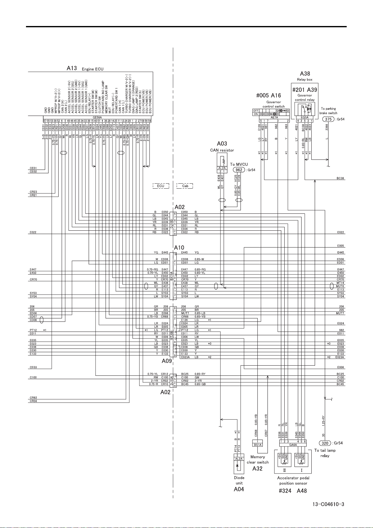
13-104
ELECTRIC CIRCUIT DIAGRAM
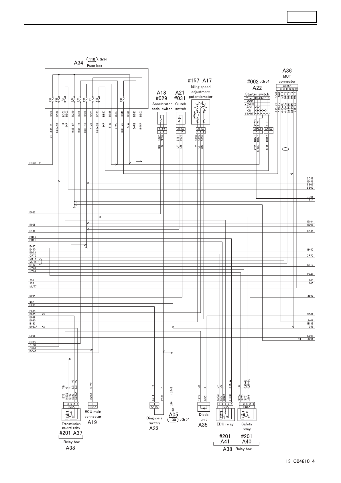
13
13-105
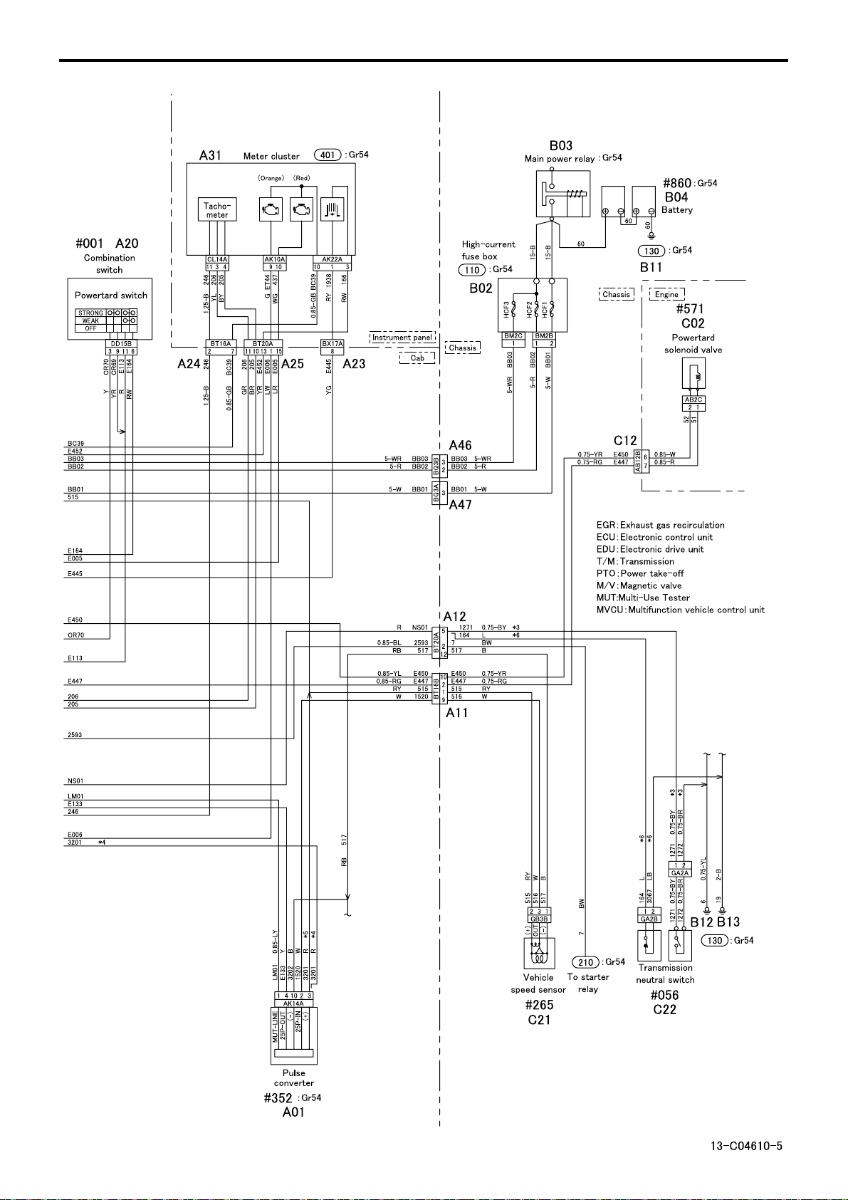
13-106
ELECTRIC CIRCUIT DIAGRAM

14-1
GROUP 14 COOLING
SPECIFICATIONS ............................................................................. 14-2
STRUCTURE AND OPERATION
1. Cooling System (Flow of Coolant) ................................................... 14-3
2. Thermostat ......................................................................................... 14-4
3. Water Pump ........................................................................................ 14-4
TROUBLESHOOTING ...................................................................... 14-5
ON-VEHICLE INSPECTION AND ADJUSTMENT
1. Inspection and Adjustment of Belt Tension ................................. 14-6
2. Inspection of Belts ....................................................................... 14-8
3. Coolant Replacement and Cleaning of Cooling System ................ 14-9
4. Air Bleeding of Cooling System ..................................................... 14-11
5. Gas Leakage Test ............................................................................ 14-11
6. Coolant Leakage Test....................................................................... 14-11
DISCONNECTION AND CONNECTION
OF HOSES AND PIPES .................................................................. 14-12
RADIATOR AND FAN SHROUD ..................................................... 14-16
SURGE TANK .................................................................................. 14-24
COOLING FAN AND BELT............................................................... 14-26
WATER PUMP................................................................................... 14-28
THERMOSTAT .................................................................................. 14-34

14-2
Item Specifications
Cooling system Forced water circulation system
Water pump Belt-driven type
Thermostat Wax pellet, bottom bypass type (with jiggle valve)
Automatic cooling fan coupling Continuous control type
Radiator Tube and corrugated fin type
Coolant capacity dm
3
{L} 41 {41}
SPECIFICATIONS
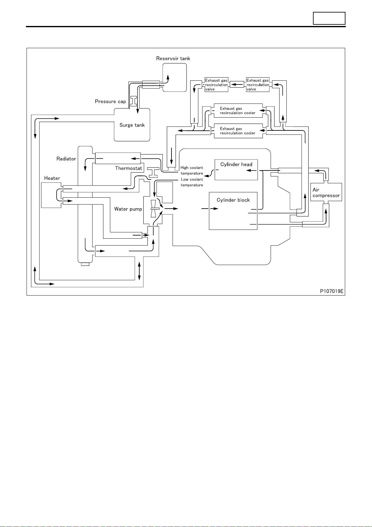
14
14-3
1. Mitsubishi 6M70 Cooling System (Flow of Coolant)
STRUCTURE AND OPERATION
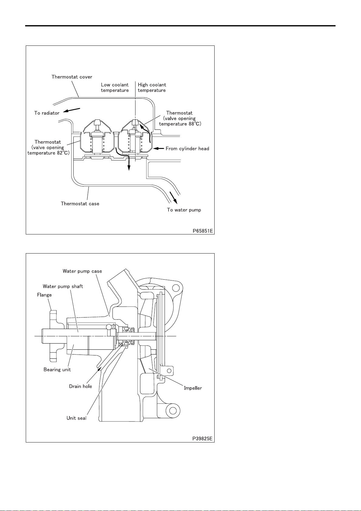
14-4
2. Mitsubishi 6M70 Thermostat
• The thermostat is a bottom bypass
type that uses a wax-filled pellet as its
flow-regulating element. When the
wax is heated, it melts from solid to liq-
uid, changing its total volume. This al-
lows the valve to open or close in
accordance with the coolant tempera-
ture, regulating and adjusting the flow
of coolant to the radiator and to the
water pump (bypassing the radiator).
3. Mitsubishi 6M70 Water Pump
• The water pump has a drain hole to
prevent coolant from entering the unit
bearing in case of a defect in the unit
seal.
STRUCTURE AND OPERATION
14
14-5
Symptoms
Overheating (poor cooling)
Overcooling
Abnormal noise
Excessive coolant loss
Reference Gr
Possible causes
Belt
Loose or damaged O O
Excessive tension O
Oil on belt O
Water pump
Incorrectly mounted water pump O O
Defective gasket O O
Defective bearing unit O O
Defective impeller O
Defective unit seal O O
Fit of bearing unit on flange and impeller too loose O O
Thermostat
Incorrectly mounted case O O
Defective gasket O O
Valve opening temperature too high
(valve remains closed)
O
Valve opening temperature too low (valve remains open) O
Leakage from coolant temperature sensor O O
Radiator
Clogged core O
Cracked core and/or separation in welds O O
Automatic cooling fan
coupling
Defective bearing O O
Damaged bimetal O
Contaminated bimetal O O
Silicon oil leakage O O
Oil cooler
Incorrectly mounted oil cooler O O
Gr12
Defective gasket O O
Cylinder head
Incorrectly mounted cylinder head O O
Gr11
Defective gasket O O
Poorly airtight pressure cap O
Insufficient coolant amount, contaminated coolant O
Clogged or scaled coolant passage O
Incorrectly connected hoses O O
Excessively low exterior temperature O
Exhaust gas recircula-
tion related
Defective gasket O O
Gr17
Incorrectly mounted exhaust gas recirculation piping O O
Air compressor
Defective gasket O O
Gr11
Incorrectly mounted water pipe O O
TROUBLESHOOTING
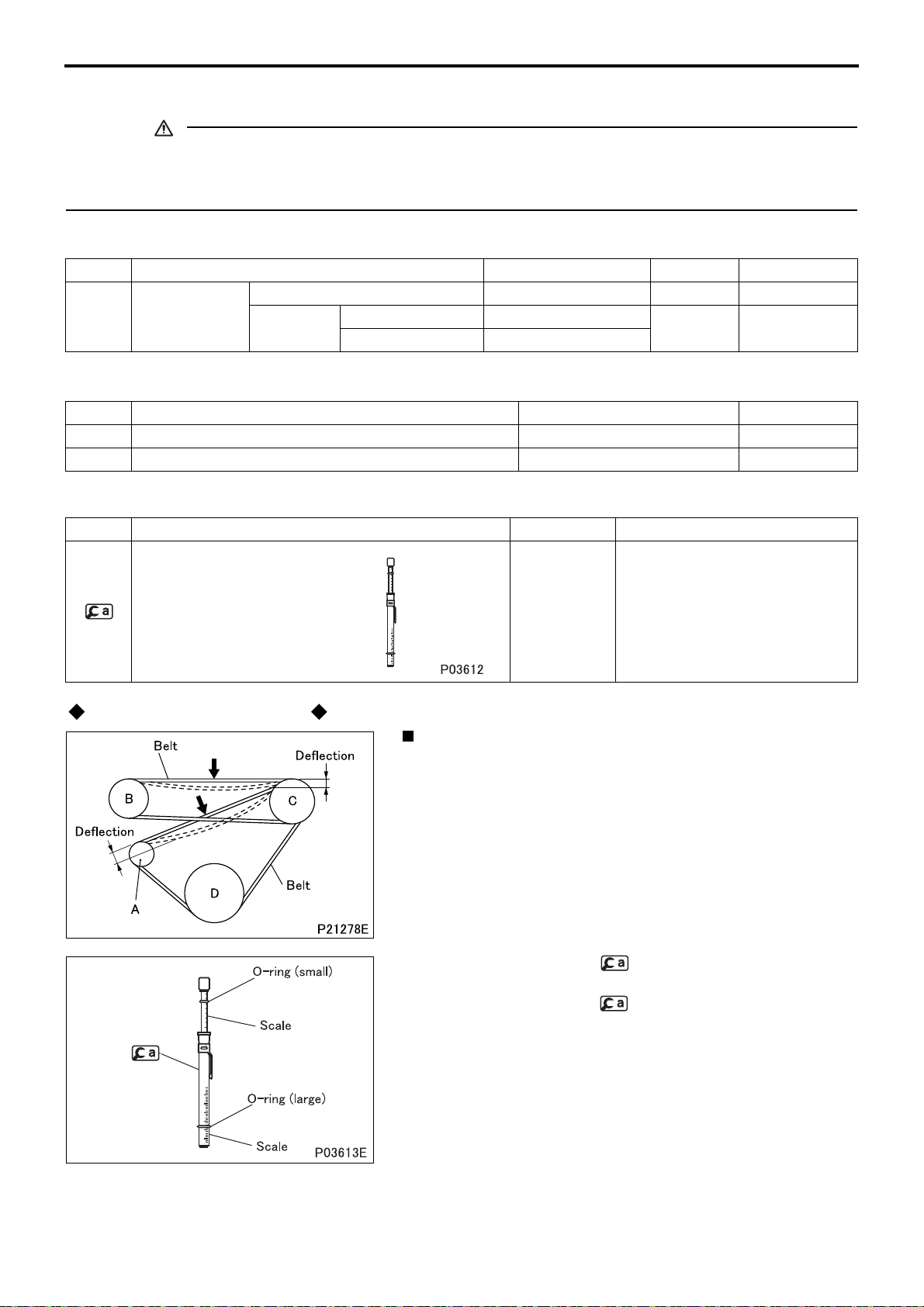
14-6
1. Inspection and Adjustment of Belt Tension
CAUTION
• Be careful not to allow engine oil to smear the belt. A belt smeared with oil slips, resulting in reduced
cooling efficiency.
• When replacing the belts, replace them as a set to prevent differences in tension between the two belts.
Service standards (Unit: mm)
Tightening torque (Unit: N·m {kgf·m})
Special tools
Inspection after installation
Inspection: Tension of belts
• Press each belt at a central portion between pulleys with a force
of approximately 98 N {10 kgf} as shown in the illustration and
measure the amount of deflection of the belt.
A: Alternator pulley
B: Compressor pulley (for air conditioner)
C: Water pump pulle
y
D: Crankshaft pulley
• Place the small O-ring on at the scale mark corresponding
to 98 N {10 kgf} (press force).
• Place the large O-ring on at the scale mark corresponding
to the maximum permissible deflection value specified for the
belt.
Location Maintenance item Standard value Limit Remedy
– Belt tension
For air conditioner 15 to 20 – Adjust
For alterna-
tor
When new 19 to 24
– Adjust
When reused 25 to 30
Mark Parts to be tightened Tightening torque Remarks
– Nut (for alternator retention) 82 {8.4} –
– Bolt (for cooler compressor retention) 19.6 to 24.5 {2.0 to 2.5} –
Mark Tool name and shape Part No. Application
Belt tension gauge MH062345 Measurement of tension of belt
ON-VEHICLE INSPECTION AND ADJUSTMENT
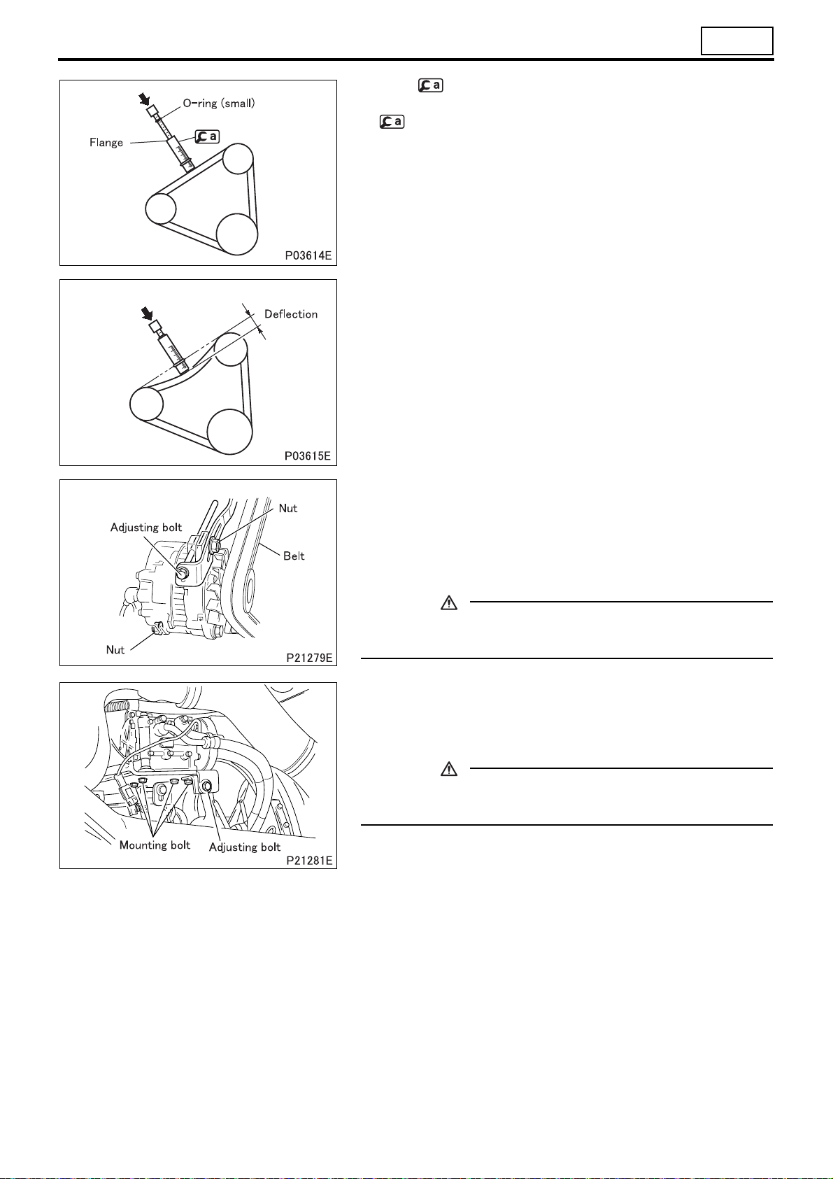
14
14-7
• Place at a central portion between pulleys of the V-belt and
push the handle (indicated by the arrow in the illustration) until
indicated by arrow touches the O-ring.
• Measure the amount of deflection of the V-belt.
• If the measurement deviates from the standard value, adjust as
follows.
Adjustment of belt
(1) Belt for alternator
• Loosen the alternator mounting nuts (2 locations) and adjust the
tension of the belt with the adjusting bolt.
• When the adjustment is completed, tighten the bolts and nuts
securely.
CAUTION
• Excessive tension in belts may damage the belts and relat-
ed bearings.
(2) Belts for air conditioner
• Loosen the cooler compressor mounting bolts (4 places) and ad-
just the tension of the belt with the adjusting bolt.
• When the adjustment is completed, tighten the bolts securely.
CAUTION
• Excessive tension in belts may damage the belts and relat-
ed bearings.
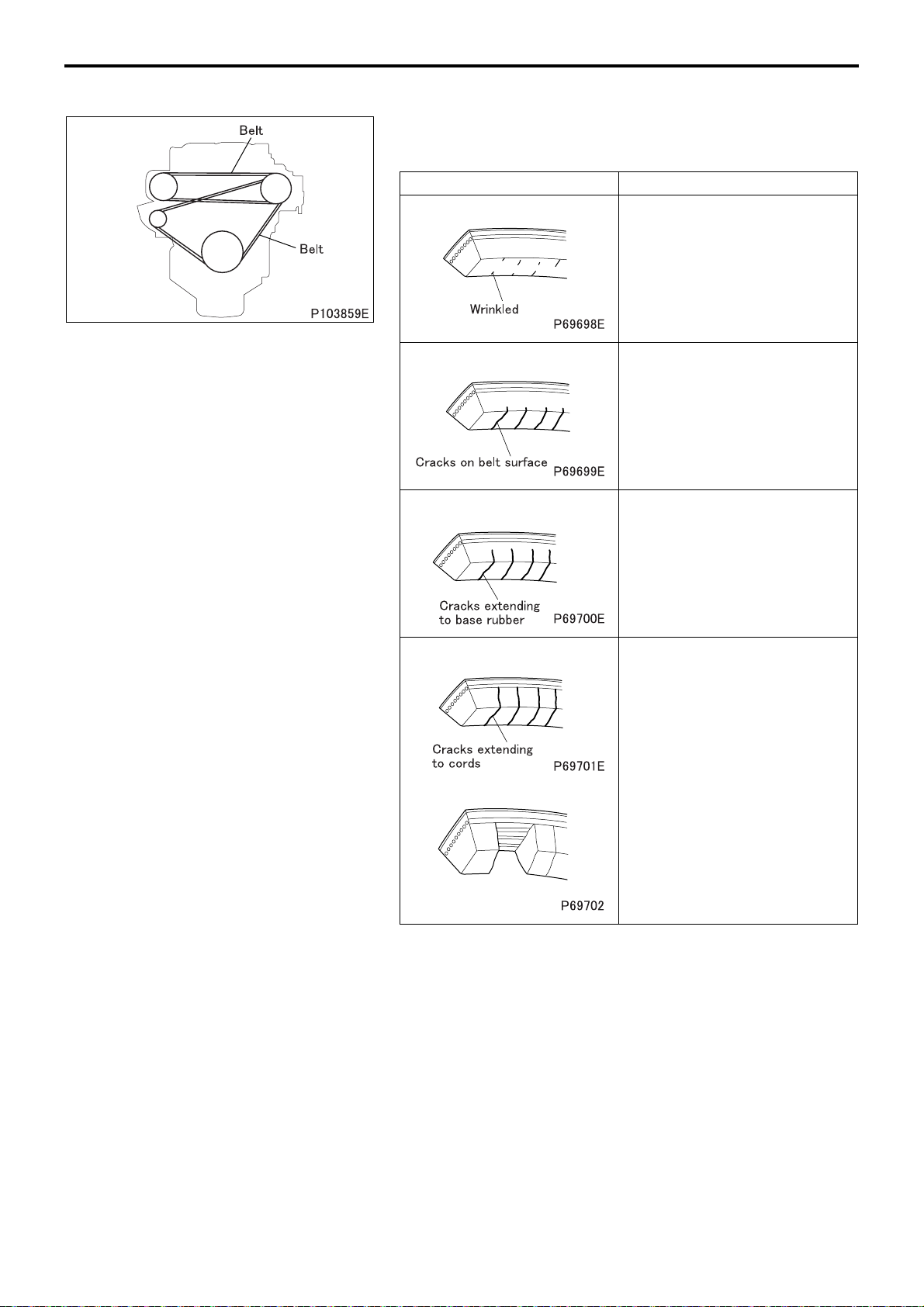
14-8
2. Inspection of Belts
• Visually check the belt for a crack or damage.
• If there is any abnormality, replace the belt.
Belt condition Remaining service life (reference)
• The driving distance over the
which the belt can still be used is
at least as long as that over which
the belt has been used since the
vehicle was new or since the belt
was replaced (whichever is more
recent).
• The driving distance over the
which the belt can still be used is
about half of that over which the
belt has been used since the vehi-
cle was new or since the belt was
replaced (whichever is more re-
cent).
• The driving distance over the
which the belt can still be used is
about a quarter of that over which
the belt has been used since the
vehicle was new or since the belt
was replaced (whichever is more
recent).
• The belt has reached the end of
its service life and must be re-
placed.
ON-VEHICLE INSPECTION AND ADJUSTMENT
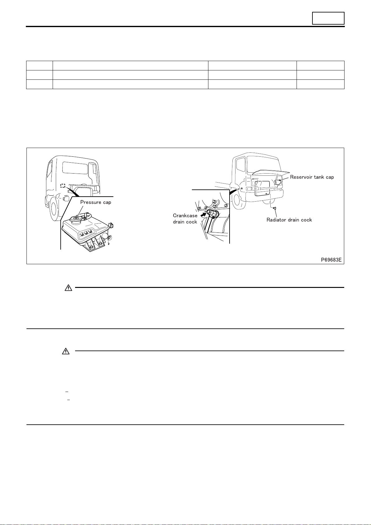
14
14-9
3. Coolant Replacement and Cleaning of Cooling System
Tightening torque (Unit: N·m {kgf·m})
• Using the radiator for extended periods of time without cleaning can increase chance of rust and scale formation,
which may cause engine overheating. The cooling system must be cleaned periodically.
Use a coolant containing the FUSO DIESEL LONGLIFE COOLANT additive and soft water in the specified pro-
portions. (See the Owner’s Handbook for instructions on the use of the additive.)
3.1 Draining of coolant
• Before draining the coolant, loosen the pressure cap to reduce the pressure in the cooling system. Remember to
drain the coolant out of the reservoir tank as well.
WARNING
• Drain the coolant only after it has cooled sufficiently to avoid getting scalded.
• Opening the pressure cap while the coolant temperature is still high can cause hot coolant to spray
out. Cover the pressure cap with a cloth, and loosen it slowly to let the pressure out before opening it
fully.
3.2 Cleaning procedure
CAUTION
• Water used for flushing the cooling system must be soft water that has a property meeting the require-
ments indicated below. Using hard water will cause scale and rust to form in the system.
Required properties of soft water
Total hardness.......................... 300 ppm or less
Sulfate SO .............................. 100 ppm or less
Chloride CI ............................. 100 ppm or less
Total dissolved solids.............. 500 ppm or less
pH .............................................. 6 to 8
• Keep the coolant temperature at approximately 90°C so that the thermostat valve remains open and coolant con-
tinues to circulate in the radiator.
• For the sake of convenience you can raise the coolant temperature quickly by covering the front of the radiator
with corrugated cardboard or something similar.
• In cases where a great amount of rust has accumulated it is common for the radiator to leak as a result of clean-
ing. Conduct a through check for leakage after cleaning.
• Select an appropriate cleaning method according to the condition of the cooling system as shown below.
Mark Parts to be tightened Tightening torque Remarks
– Radiator drain cock 2.0 {0.2} –
– Crankcase drain cock 37 {3.8} –
4
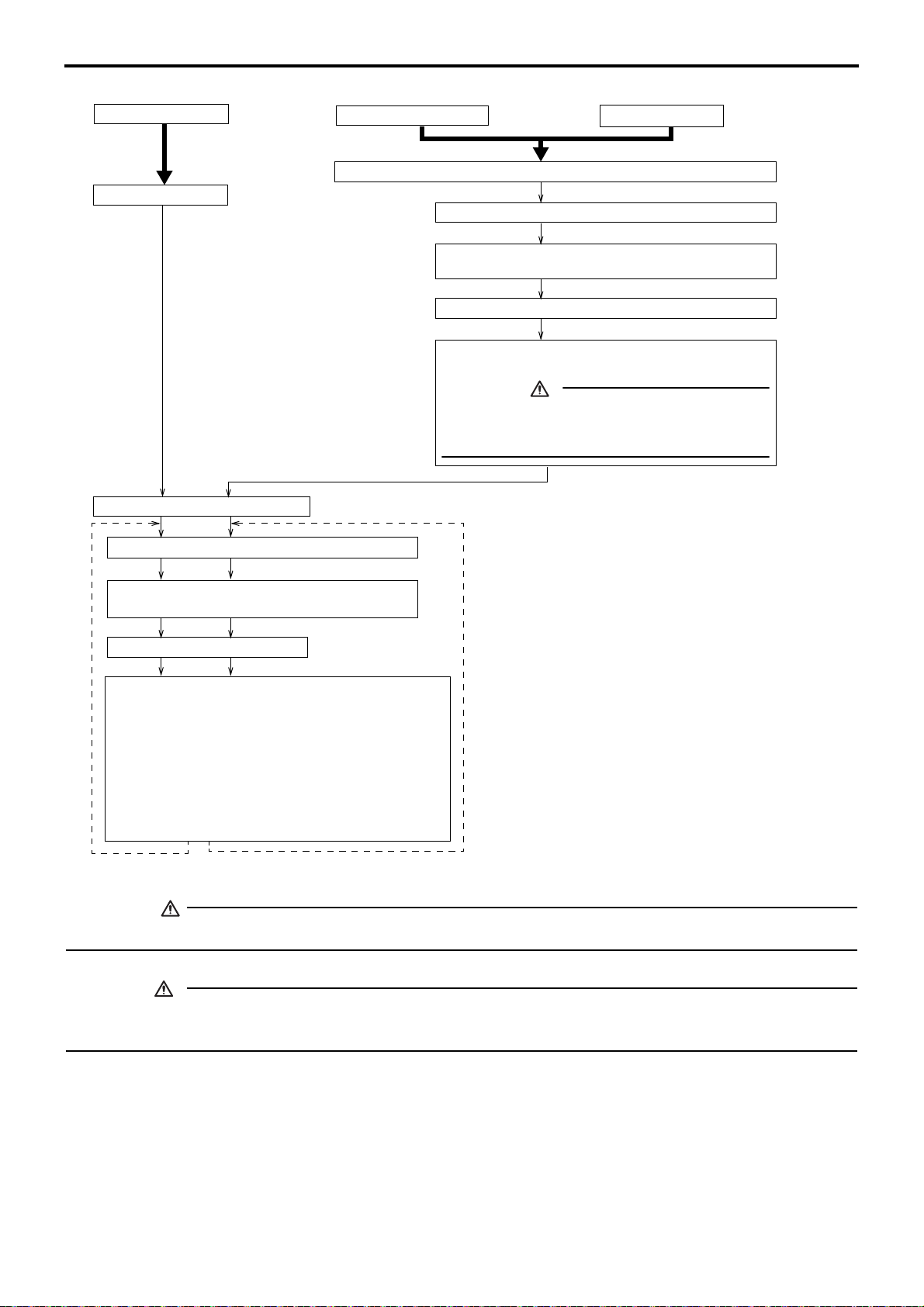
14-10
WARNING
• FUSO DIESEL LONGLIFE COOLANT is flammable. Keep it away from heat and flames.
CAUTION
• If you accidentally splash FUSO DIESEL LONGLIFE COOLANT in your eyes, wash it out immediately with
water and seek medical attention.
• Ordinary condition
• Coolant extremely dirty
• Radiator clogged
Flushing with water
Cleaning using FUSO RADIATOR CLEANER (RADIPET-7)
Drain out coolant
Make water solution of FUSO RADIATOR CLEANER
(RADIPET-7) at 5 to 10% concentration in volume.
Pour solution into surge tank.
Let the engine idle for 30 minutes with the water at approxi-
mately 90°C.
CAUTION
• Limit the engine idling period to one hour. Operating
an engine containing the cleaning solution for long-
er time may lead to damage of the cooling system.
Drain out coolant
Pour tap water (preferably hot) into the surge tank.
Let the engine idle for 10 minutes with the water
at approximately 90°C.
Cleaning is complete if drained water is clear
Repeat procedure if drained water is not clear
• After cleaning the cooling system using cleaning solu-
tion, fill it with coolant containing the specified additive as
soon as possible.
• To prevent freezing of the coolant and corrosion of the
cooling system, add the specified portion of FUSO DIE-
SEL LONGLIFE COOLANT to the coolant. (See the
Owner’s Handbook for instructions on the use of the ad-
ditive.)
Drain out water
ON-VEHICLE INSPECTION AND ADJUSTMENT
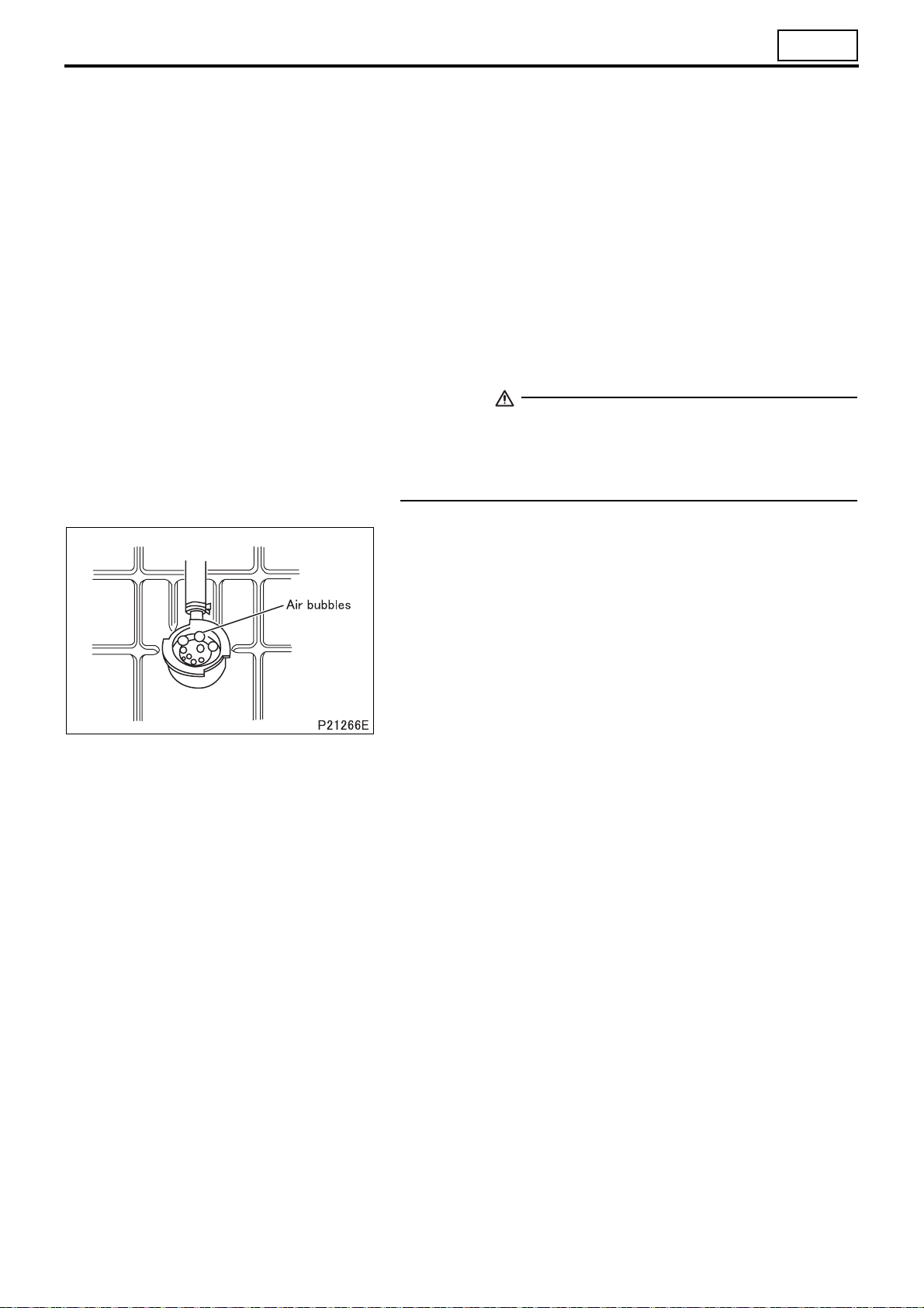
14
14-11
4. Air Bleeding of Cooling System
• If the engine is started with the coolant filled up to the neck of the surge tank, the coolant temperature rises and
the expanded coolant overflows from the neck little by little. To avoid this, fill the surge tank with a slightly smaller
quantity of the coolant.
• With the pressure cap removed and the coolant temperature at 90°C, let the engine idle in order to bleed air com-
pletely out of the cooling system.
• After air bleeding is completed, refill the reservoir tank with coolant as needed.
5. Gas Leakage Test
• Presence of air or exhaust gas in coolant accelerates corrosion
of the cooling system components. To prevent this, carry out air/
gas leakage tests in accordance with the following procedure.
• Remove the pressure cap.
WARNING
• If the engine is hot, boiling coolant may spurt out from the
filler port when the pressure cap is loosened. To avoid
burning yourself, make sure to remove the pressure cap
only when the coolant is cold.
• Run the engine until the coolant temperature rises to approxi-
mately 90°C.
• If air bubbles appear continuously through the filler port, there is
air or exhaust gas penetrating into the cooling system.
• Presence of air in coolant can be an indication of loose cylinder
head bolts, loose water pump mounting bolts, loose hose con-
nections, and/or a damaged hose.
• Presence of exhaust gas in coolant can be an indication of a
damaged cylinder head gasket and/or cracks in the cylinder
head.
6. Coolant Leakage Test
• Ensure that there is no coolant leakage from coolant system during idling.
• If any leakage is found, check for the mounting condition. If there is looseness, tighten the part to the specified
torque. If there are cracks or damages, replace the defective part with a new one. (See later section.)
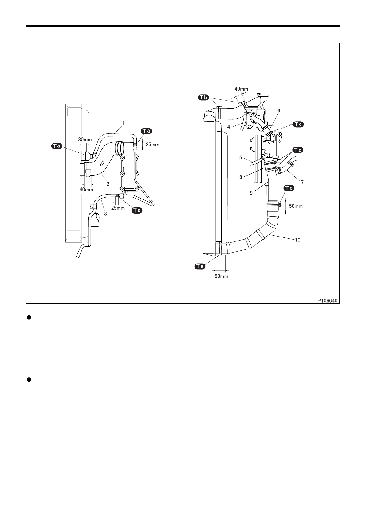
14-12
Periphery of Radiator
Removal sequence
Installation sequence
Follow the removal sequence in reverse.
• Install each hose clamp to the angle indicated in the illustration so that sufficient clearance is assured between the
hose clamp and its surrounding parts.
1 Supply hose
2 Inlet hose
3 Overflow hose
4 Heater hose
5 Heater hose
6 Water hose
7 Hose
8 Water hose
9 Water pipe
10 Outlet hose
DISCONNECTION AND CONNECTION OF HOSES AND PIPES
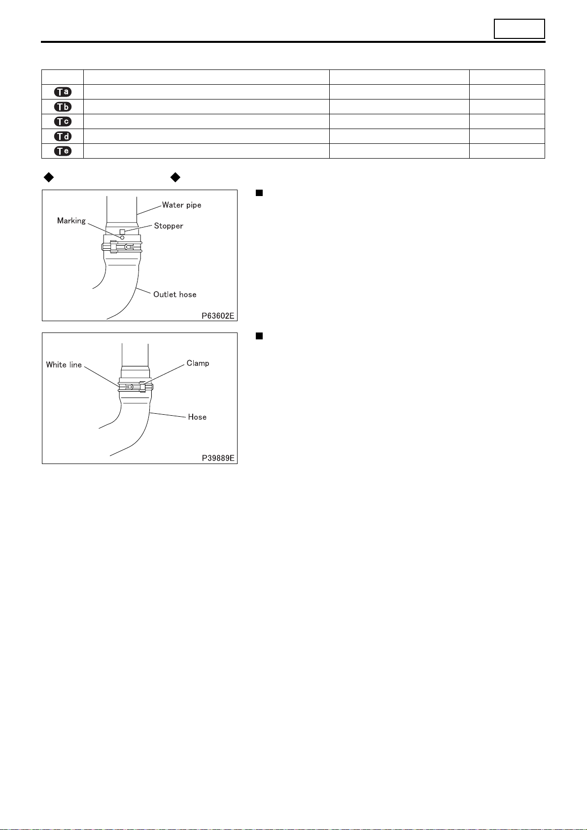
14
14-13
Tightening torque (Unit: N·m {kgf·m})
Installation procedure
Installation: Outlet hose
• Install the outlet hose so that its marking faces the stopper of the
water pipe.
Installation: Hose
• Install the hose marked with a white line so that this white line is
placed in the center of the clamp.
Mark Parts to be tightened Tightening torque Remarks
Hose clamp 4.0 ± 0.5 {0.4 ± 0.05} –
Hose clamp 5.0 ± 0.5 {0.5 ± 0.05} –
Hose clamp 3.5 to 4.5 {0.35 to 0.45} –
Hose clamp 4.4 {0.45} –
Hose clamp 6.5 ± 0.5 {0.7 ± 0.05} –
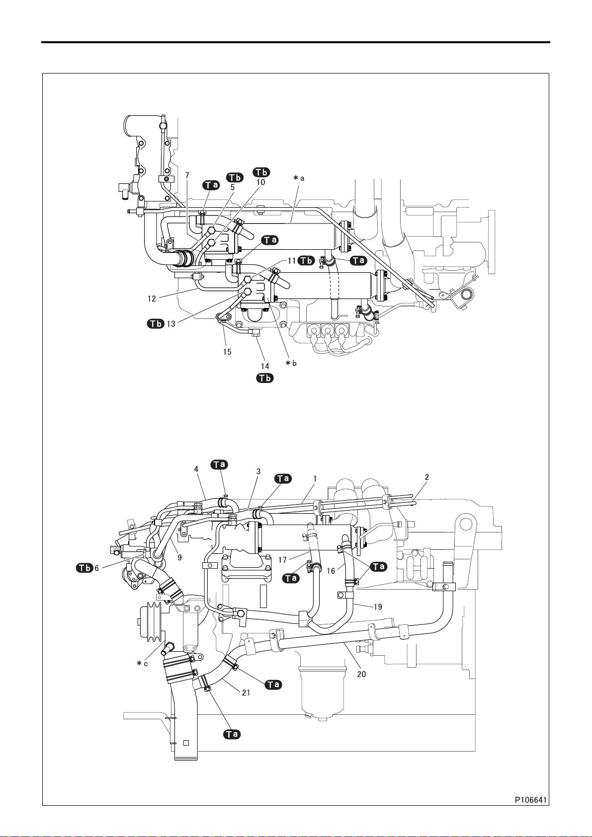
14-14
Periphery of Engine
DISCONNECTION AND CONNECTION OF HOSES AND PIPES
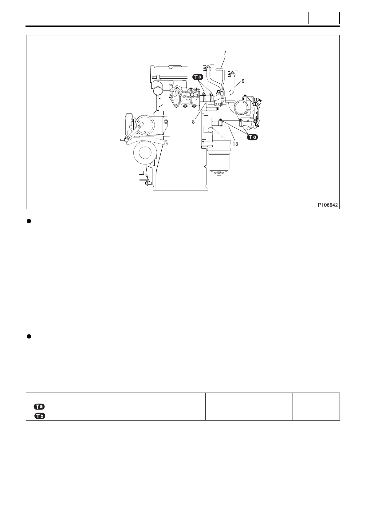
14
14-15
Removal sequence
Installation sequence
Follow the removal sequence in reverse.
• Install each hose clamp to the angle indicated in the illustration so that sufficient clearance is assured between the
hose clamp and its surrounding parts.
Tightening torque (Unit: N·m {kgf·m})
Mark Parts to be tightened Tightening torque Remarks
Clamp 3.9 {0.4} –
Eyebolt (water pipe mounting) 39 {4.0} –
1 Air pipe
2 Water pipe
3 Water hose
4 Water hose
5 Eyebolt
6 Eyebolt
7 Water pipe
8 Water hose
9 Water pipe
10 Eyebolt
11 Eyebolt
12 Water pipe
13 Eyebolt
14 Eyebolt
15 Water pipe
16 Water hose
17 Water hose
18 Water hose
19 Water pipe
20 Water pipe
21 Water hose
*
a: Exhaust gas recirculation
cooler
*
b: Exhaust gas recirculation
valve
*
c: Water pump
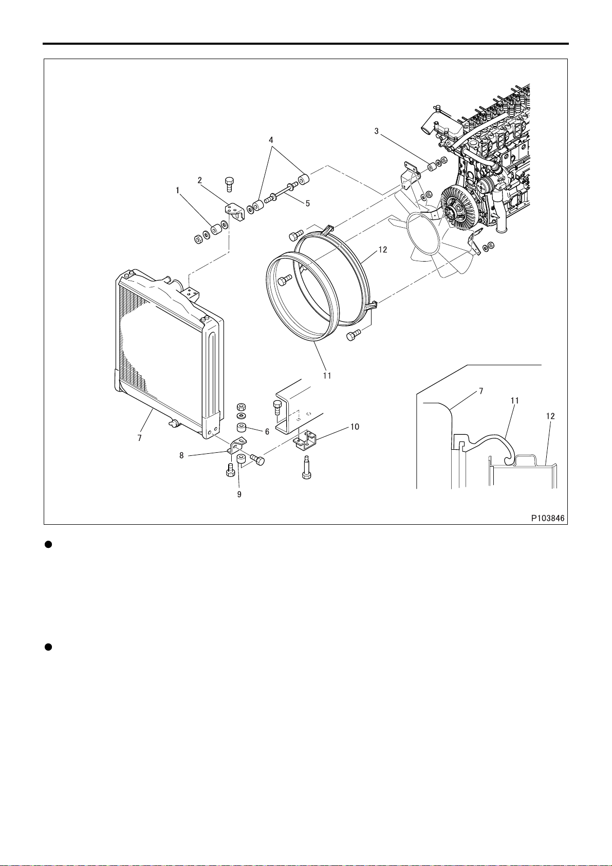
14-16
Removal sequence
Installation sequence
Follow the removal sequence in reverse.
• Refer to the previous section “DISCONNECTION AND CONNECTION OF HOSES AND PIPES” for the correct
insertion depth of radiator hoses into the pump as well as the correct tightening torque of clamps.
1 Cushion rubber
2 Front thrust rod bracket
3 Cushion rubber
4 Cushion rubber
5 Thrust rod
6 Cushion rubber
7 Radiator
(See later section.)
8 Radiator bracket
9 Cushion rubber
10 Radiator support
11 Shroud seal
12 Fan shroud
RADIATOR AND FAN SHROUD
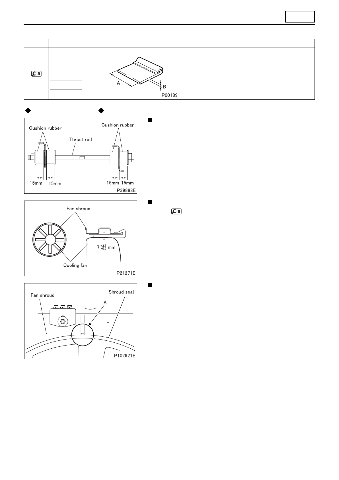
14
14-17
Special tools (Unit: mm)
Installation procedure
Installation: Thrust rod
• Tighten nuts so that the thickness of cushion rubbers on both
ends of the thrust rod is to the dimension shown in the illustra-
tion.
Installation: Fan shroud
• Using , adjust the clearance between the fan shroud and
cooling fan blades to the dimension shown in the illustration over
the entire circumference.
Installation: Shroud seal and fan shroud
• Install the shroud seal and fan shroud while aligning the section
A as shown in the illustration.
Mark Tool name and shape Part No. Application
ME294842
Adjusting clearance between fan
shroud and cooling fan blades
Tip clearance
spacer
AB
50 7
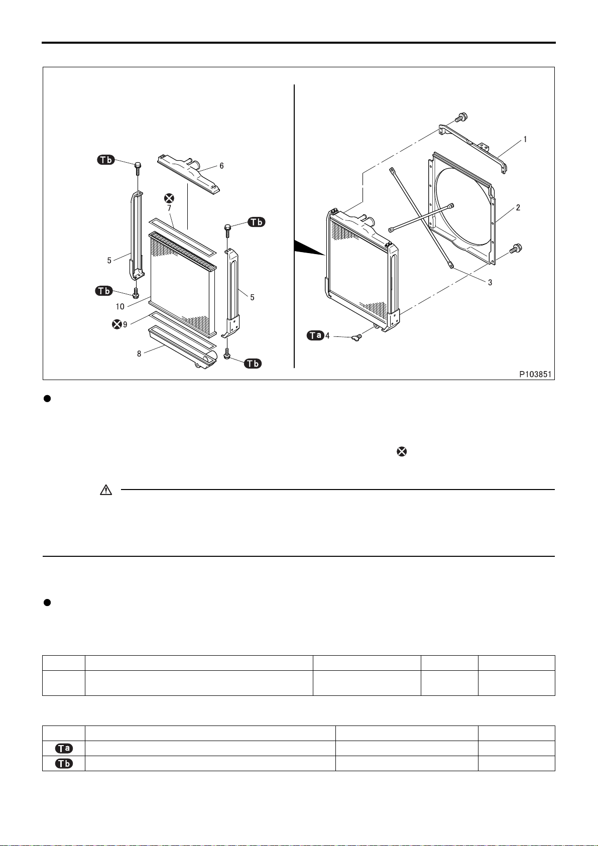
14-18
Radiator
Disassembly sequence
CAUTION
• Gently handle upper tank and lower tank, since they are made of a resin that can break on impact.
• If there are two paint marks on the joint between the core and upper tank or on the joint between the core
and lower tank (which indicates that the tank retaining tabs have been crimped twice before), replace the
core with a new part.
• Do not disassemble radiator unless there is an abnormality.
Assembly sequence
Follow the disassembly sequence in reverse.
Service standards
Tightening torque (Unit: N·m {kgf·m})
Location Maintenance item Standard value Limit Remedy
–
Air leakage from radiator
(air pressure: 177 kPa {1.8 kgf/cm
2
})
0 cm
3
{0 mL} – Rectify or replace
Mark Parts to be tightened Tightening torque Remarks
Drain cock 2 {0.2} –
Bolt (side member mounting) 13 {1.3} –
1 Thrust rod bracket
2 Radiator shroud
3 Cross stay
4 Drain cock
5 Side member
6 Upper tank
7 Packing
8 Lower tank
9 Packing
10 Core
: Non-reusable parts
RADIATOR AND FAN SHROUD
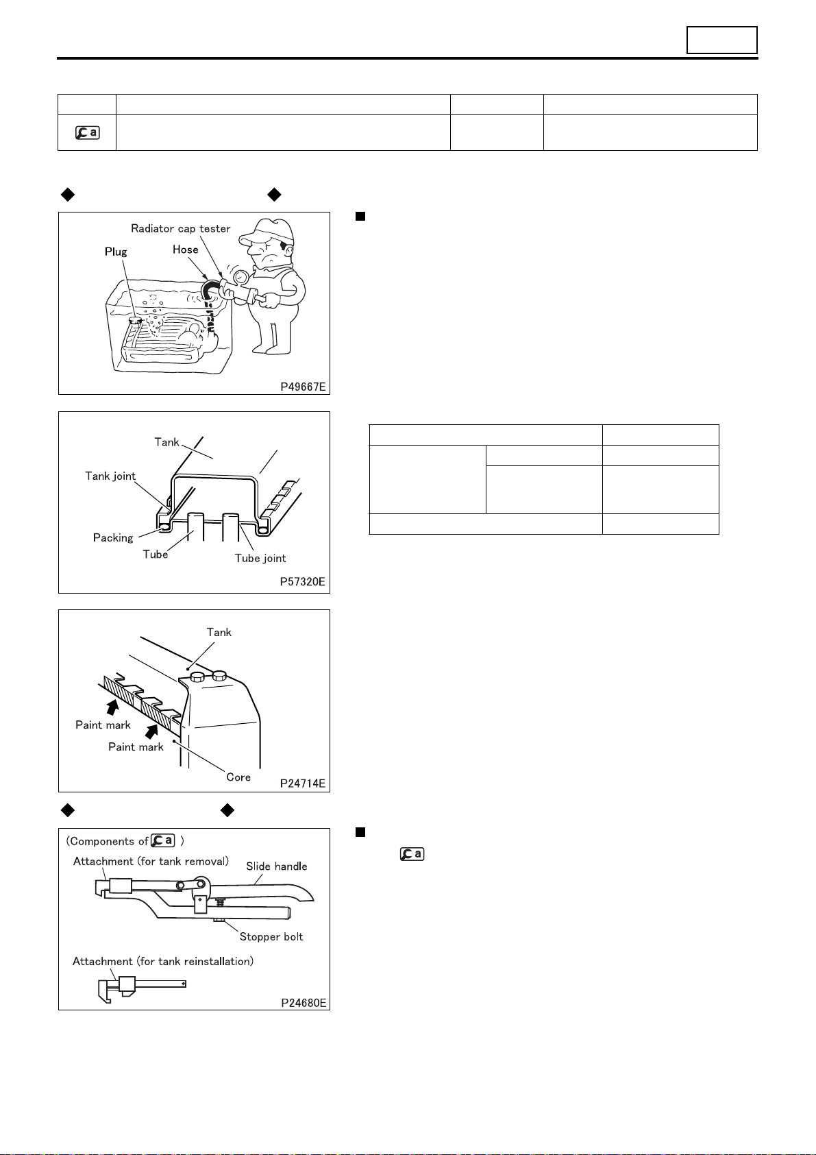
14
14-19
Special tools
The indicated part number is T.RAD’s part number.
Inspection before removal
Inspection: Air leakage from radiator
• Install hose and radiator cap tester and plug to upper tank.
• Insert plug in lower tank, and immerse the entire body of the ra-
diator in water.
• Apply a specified air pressure using radiator cap tester, and
check for any air leakage.
• If any leakage is found, repair or replace radiator.
• Replace the following parts according to the leakage location.
• If there are two paint marks on the joint between the core and
upper tank or on the joint between the core and lower tank
(which indicates that the tank retaining tabs have been crimped
twice before), replace the core with a new part.
• Paint a mark for each core replacement. The upper and lower
core replacement should be counted and marked separately.
Removal procedure
Removal: Upper tank and lower tank
• Use , for removal and reinstallation of the tanks.
Mark Tool name and shape Part No. Application
Lock-and-break tool
J94-Z013
-10000
Removal of upper and lower tanks
Area of leakage Cause
Upper tank
Lower tank
Tank Cracked tank
Tank joint
Defective crimping
Defective packing
Cracked tank
Tube; Tube joint Cracked tube
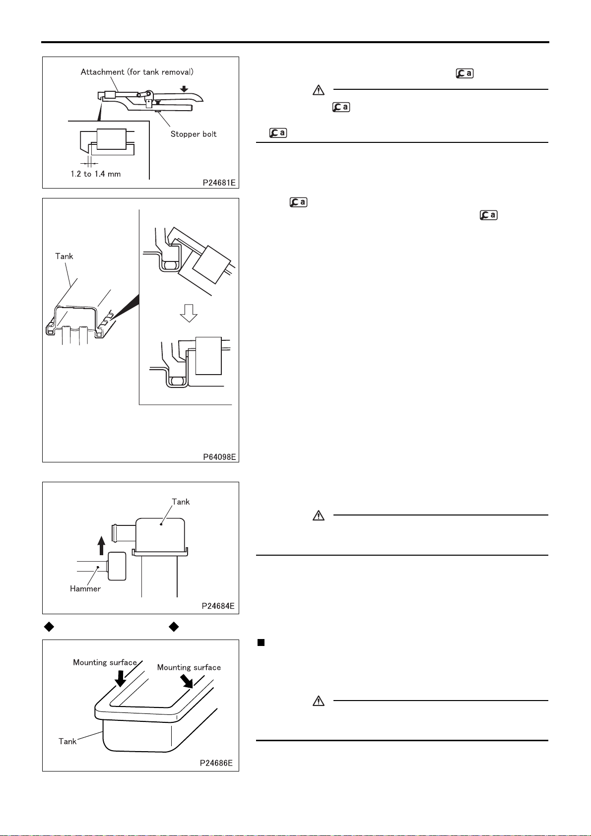
14-20
• Adjust the stopper bolt until the gap dimension shown in the il-
lustration is obtained on the attachment of .
CAUTION
• Before using , be sure to set the gap to the specified di-
mension by adjusting the stopper bolt. Otherwise, damaged
will result.
• Use to bend open tabs of retain tank in place.
• After tabs are bent open, squeeze the handle
of
to straight-
en tabs as illustrated.
• After straightening all tabs in the perimeter, hold the pipes con-
nected to the inlet/outlet, and remove tank.
• If it is difficult to remove tank lightly hit with rubber hammer (or
plastic hammer) to remove.
CAUTION
• Gently handle tanks, since they are made of a resin that can
break on impact.
Inspection procedure
Inspection: Tank surface where core is to be mounted
• Check and clean the tank surface where the core is to be mount-
ed for cleanliness, damage, etc.
• If any abnormality is found, replace the tank.
CAUTION
• To prevent adhesion of foreign substances on mounting
surface, conduct work with bare hands.
RADIATOR AND FAN SHROUD
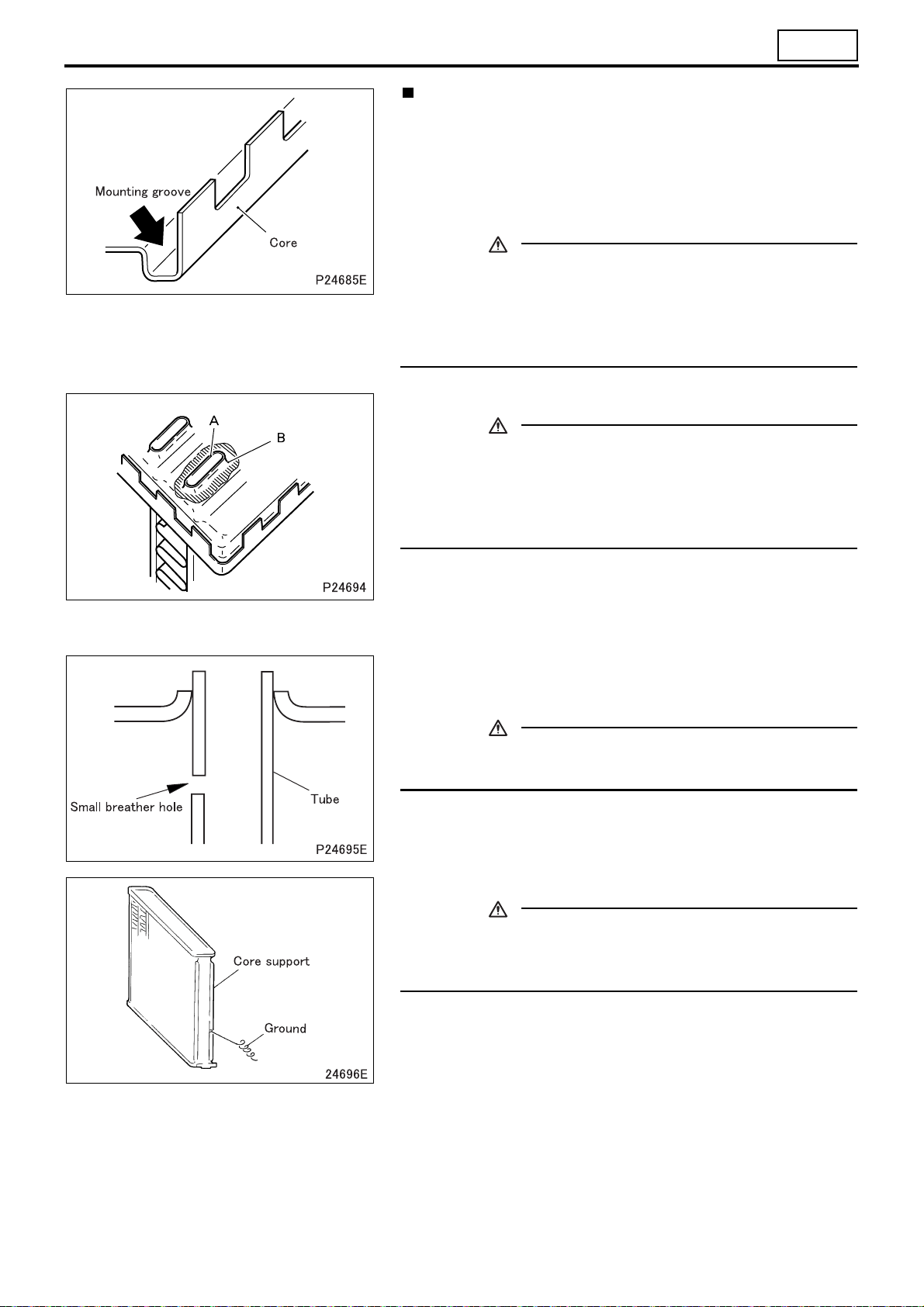
14
14-21
Inspection: Core groove where tank is to be mounted
• Check the groove on the core where the tank is to be mounted
for adhesion of foreign substances or cracks.
• If foreign substances are found, rub the area with #1000 sand-
paper or the like gently so as to avoid scratching the surface, or
use compressed air to remove them.
• If there are cracks in the groove, repair or replace.
CAUTION
• If the packing and tank are installed onto the core without
removing foreign substances from the groove, coolant leak-
age will result. Be sure to inspect and clean the tank mount-
ing groove along the entire periphery (even a hair can cause
leakage).
Repairing core
CAUTION
• The core is repaired by means of tungsten inert-gas arc
welding (TIG welding), which should only be performed by a
skilled welder.
• It is extremely dangerous to weld on a wet core. Before
welding, ensure that the core is completely dry.
• Using a stainless wire brush, brush both ends A of the leaky
tube and the areas B around the tube ends until the base alumi-
num is exposed.
• Before closing the tube at both ends by welding, drill a small
breather hole in the tube.
CAUTION
• If a breather hole is not provided, the tube may develop
small pinholes due to escaping air.
• Ground the core at the support.
CAUTION
• If welding is performed without the core properly grounded,
this can lead to short-circuit where the base metal may
melt.
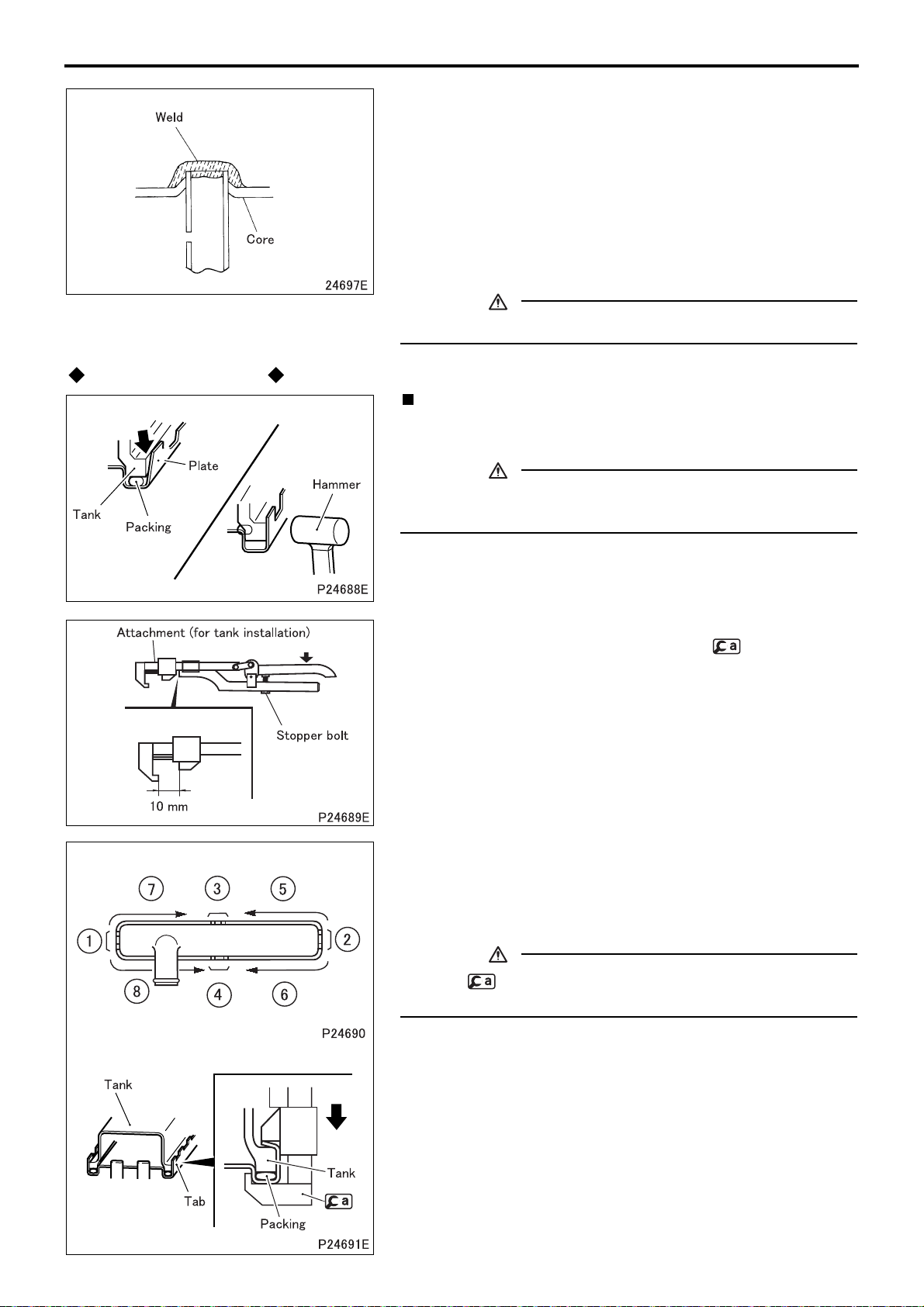
14-22
• Close both end of the tube by tungsten inert-gas arc welding
(TIG welding).
Welding conditions
• Welding rod: A4043 (approx. φ2 mm)
• Welding current: AC80A
• After welding, check for the following problems. If any of them
exist, repair again or replace the core.
• Undercut
• Bead crack
• Base metal crack
CAUTION
• Improper weld can lead to recurrence of coolant leakage.
Installation procedure
Installation: Upper tank, Lower tank
• With the tank installed, eliminate any clearance between the
tank and core plate by tapping with a rubber (or plastic) hammer.
CAUTION
• To prevent adhesion of foreign substances, use bare hands
to install the packing and tank.
• Adjust the stopper bolt until the gap dimension shown in the il-
lustration is obtained on the attachment of .
• Follow the sequence shown in the diagram, bend tabs for crimp-
ing tank.
1 to 4: Bend two tabs at the center.
5 to 8: Bend other tabs following the direction of the arrow.
CAUTION
• Since cannot be used to crimp sides 1 and 2, use pli-
ers with the tips wrapped in vinyl tape.
• After crimping the tabs onto the tank, check for coolant
leakage.
RADIATOR AND FAN SHROUD
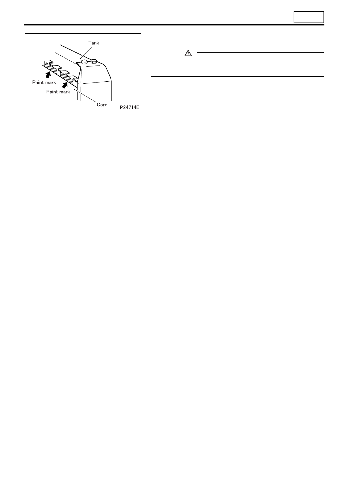
14
14-23
• Paint a mark on the core where it can be easily noticed to indi-
cate that the core has been crimped.
CAUTION
• Paint a mark on the core where it can be easily noticed to
indicate that the core has been crimped.
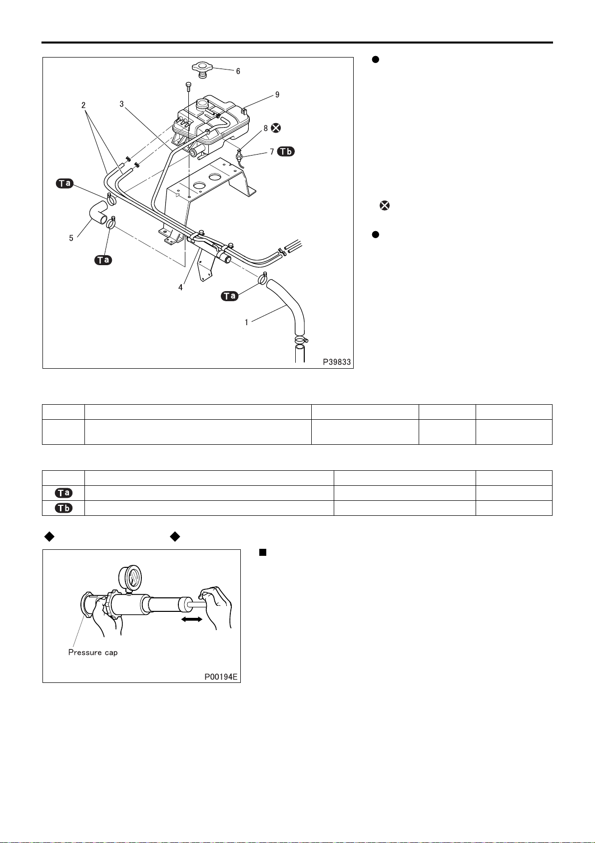
14-24
Disassembly sequence
1 Supply hose
2 Air bleeder hose
3 Overflow hose
4 Supply pipe
5 Supply hose
6 Pressure cap
7 Water level sensor
8 O-ring
9 Surge tank
: Non-reusable parts
Assembly sequence
Follow the disassembly sequence in re-
verse.
Service standards (Unit: mm)
Tightening torque (Unit: N·m {kgf·m})
Inspection procedure
Inspection: Pressure cap
(1) Pressure valve opening pressure
• If the measurement deviates from the standard value, replace
the pressure cap.
Location Maintenance item Standard value Limit Remedy
6 Pressure valve opening pressure
49 ± 9.8 kPa
{0.5 ± 0.1 kgf/cm
2
)
–Replace
Mark Parts to be tightened Tightening torque Remarks
Clamp 3 to 5 {0.3 to 0.5} –
Water level sensor 3 to 4 {0.3 to 0.4} –
SURGE TANK
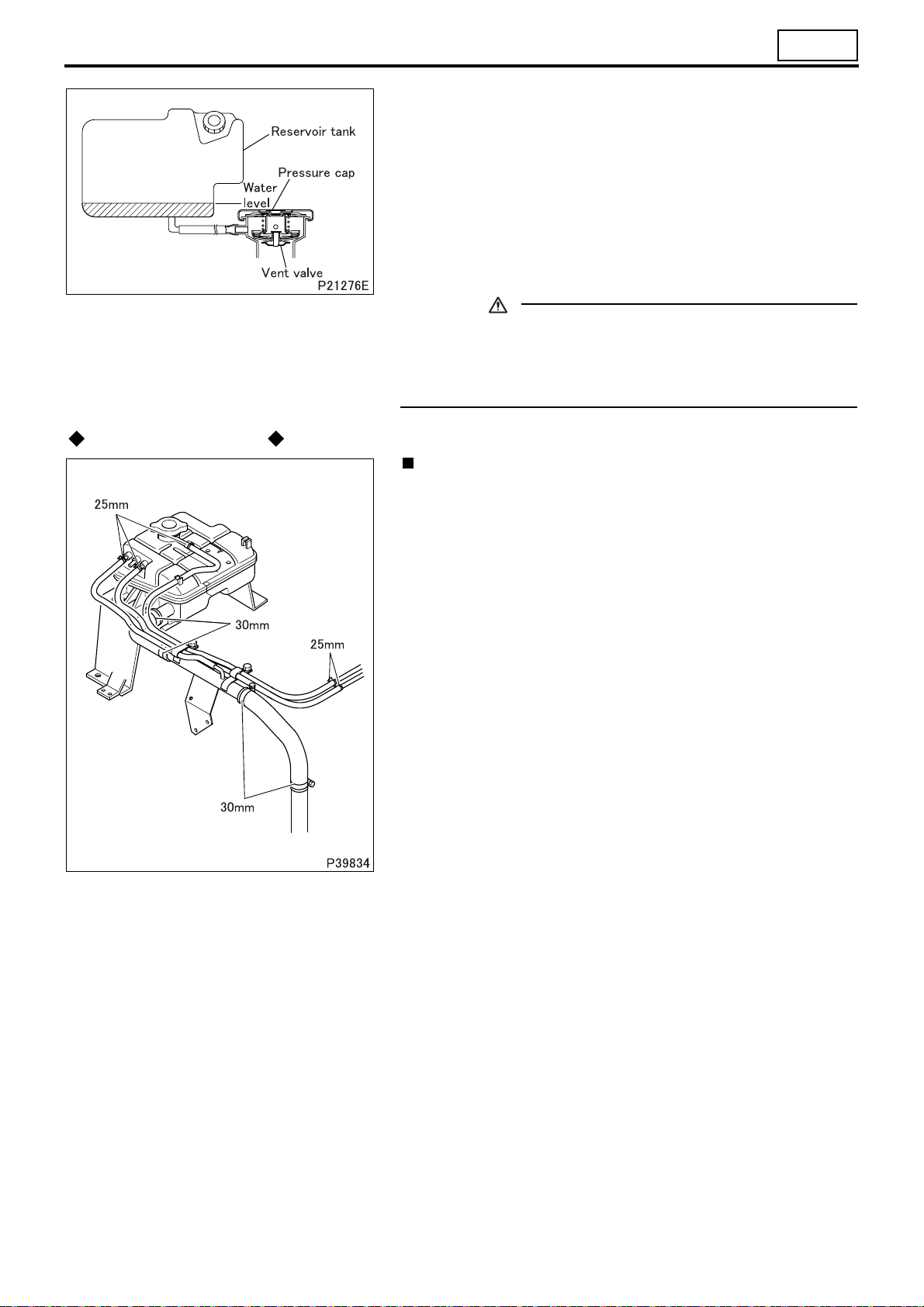
14
14-25
(2) Inspection of vent valve
• Check the water level of the reservoir tank in advance.
• Run the engine at high rpm. When the engine coolant overflows
to the reservoir tank to some extent, stop the engine.
• Leave the engine in this condition for a while. When the engine
coolant temperature becomes the atmospheric temperature,
check that the water level in the reservoir tank returns to the wa-
ter level before the engine start.
• If the water level does not lower, the vent valve is defective. Re-
place the pressure cap.
CAUTION
• Do not remove the pressure cap before the engine coolant
temperature drops to the atmospheric temperature. Other-
wise, vacuum in the radiator is lost and the engine coolant
cannot return to the reservoir tank.
Installation procedure
Installation: Hose
• The insertion depth of each hose is as shown in the illustration.
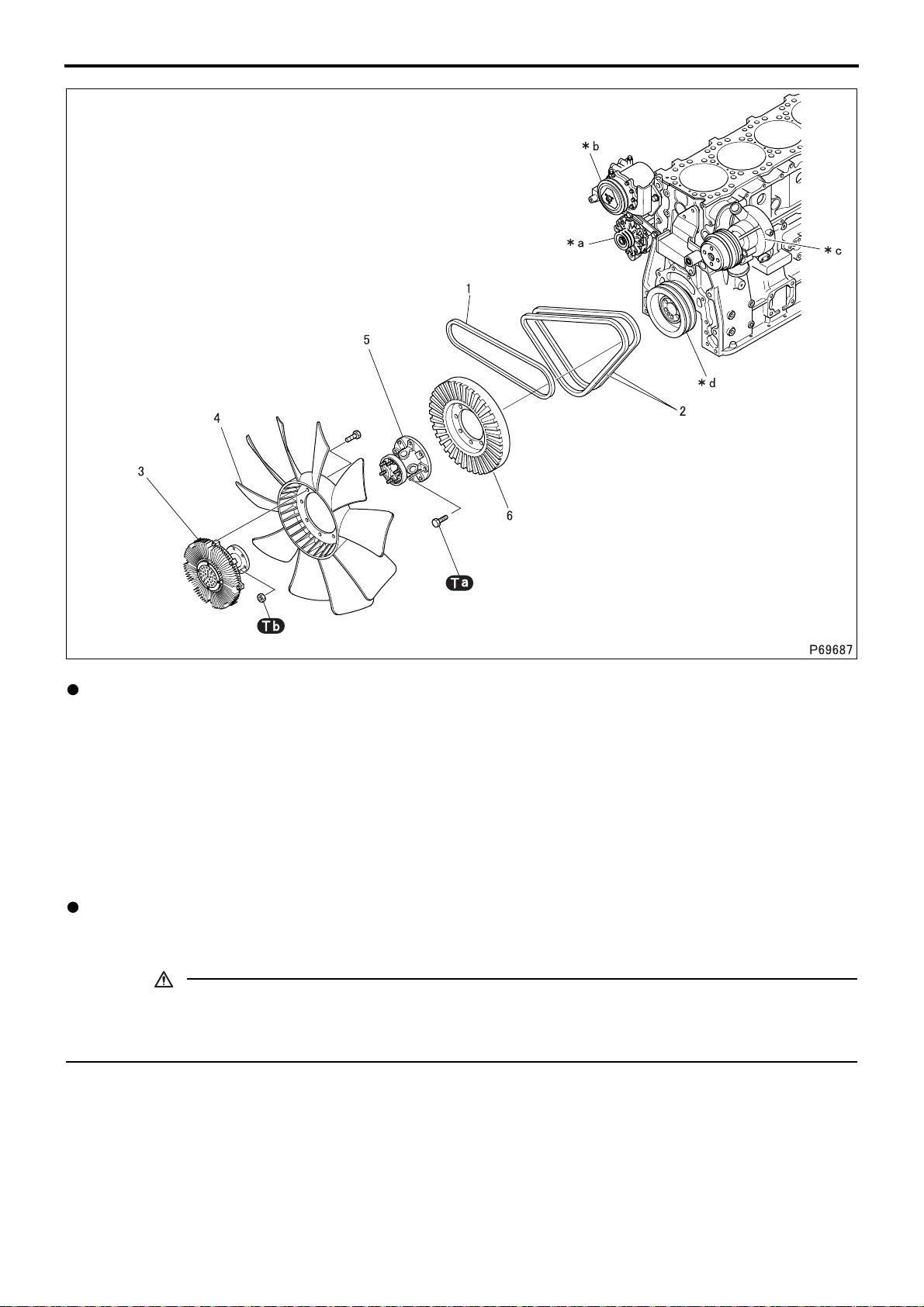
14-26
Removal sequence
• The automatic cooling fan coupling cannot be disassembled. If it is found faulty, replace the whole assembly.
Installation sequence
Follow the removal sequence in reverse.
CAUTION
• Be careful not to allow engine oil to smear the belt. A belt smeared with oil slips, resulting in reduced
cooling efficiency.
• When replacing the belts, replace them as a set to prevent differences in tension between the two belts.
• After installation, perform the inspection and adjustment of belt tension. (See “ON-VEHICLE INSPECTION AND
ADJUSTMENT.”)
1 Belt (for air conditioner)
2 Belt (for alternator)
3 Automatic cooling fan coupling
4 Cooling fan
5 Fan coupling
6 Torsional damper
*
a: Alternator
*
b: Cooler compressor
(for air conditioner)
*
c: Water pump
*
d: Crankshaft pulley
MITSUBISHI 6M70 COOLING FAN AND BELT
Mitsubishi 6M70 Engine Parts contact:
email: EngineParts@HeavyE
quipmentRestorationParts.com
Phone: 269 673 1638
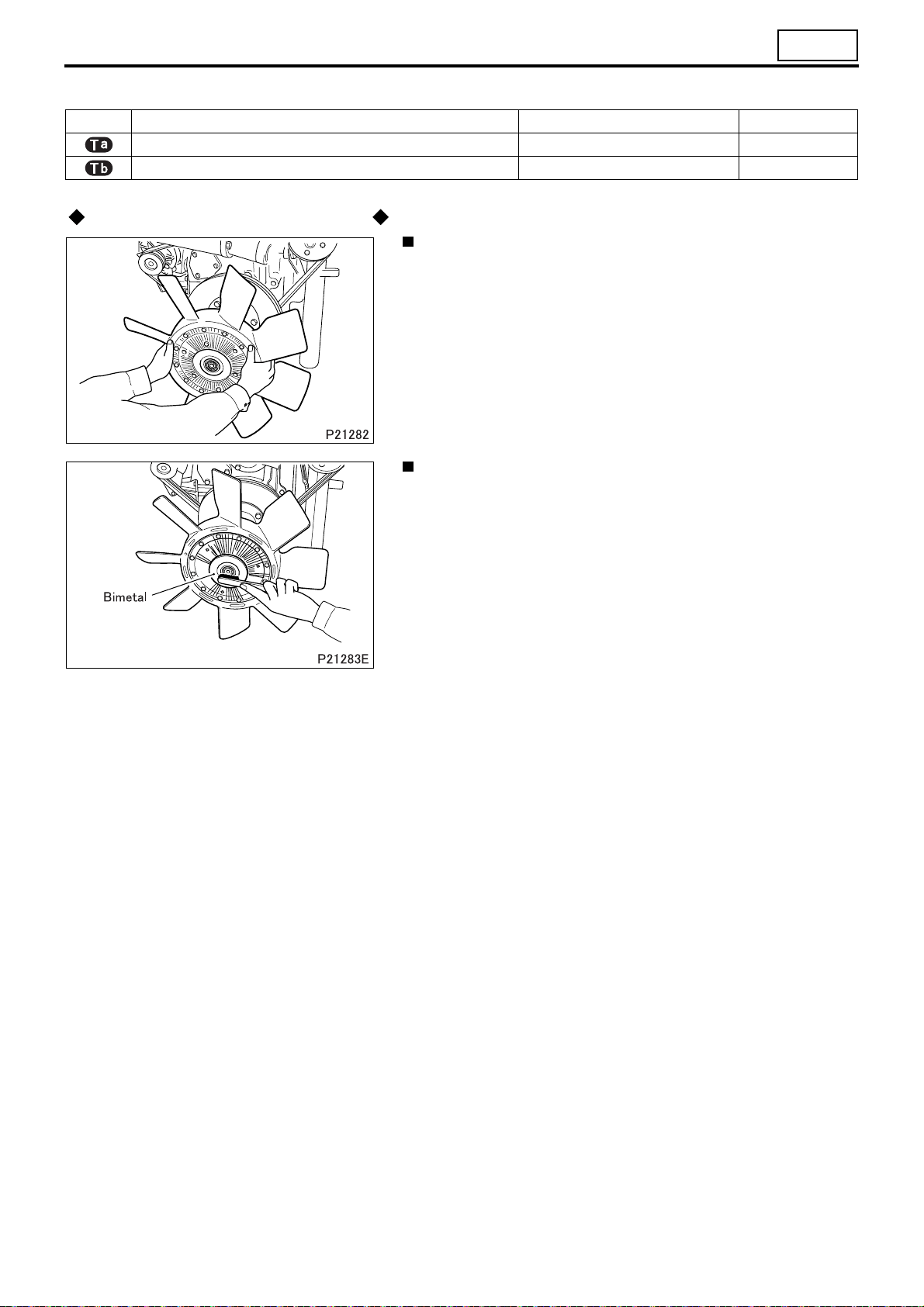
14
14-27
Tightening torque (Unit: N·m {kgf·m})
Inspection and cleaning procedure
Inspection: Automatic cooling fan coupling
• Perform the following inspection. If any abnormality is found, re-
place the automatic cooling fan coupling.
• Check for leakage of oil from the coupling body.
• Rotate the automatic cooling fan coupling by hand and check
for irregular movement or abnormal noise caused by a defect
in the bearing.
• Check for excessive axial play in the automatic cooling fan
coupling when the engine is cool.
Cleaning: Automatic cooling fan coupling
• If any foreign particles have adhered to the bimetal, remove
them carefully without applying excessive force.
Mark Parts to be tightened Tightening torque Remarks
Bolt (fan coupling mounting) 115 {12} –
Nut (automatic cooling fan coupling mounting) 50 {5.0} –
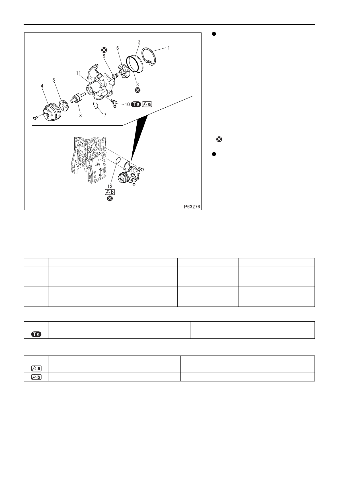
14-28
Disassembly sequence
1 Snap ring
2 Water pump cover
3 O-ring
4 Water pump pulley
5 Flange
6 Impeller
7 Wire
8 Bearing unit
9 Unit seal
10 Connector
11 Water pump case
12 O-ring
: Non-reusable parts
Assembly sequence
Follow the disassembly sequence in re-
verse except for the following.
11 → 8 → 7 → 9 → 6
• See the previous section “DISCON-
NECTION AND CONNECTION OF
HOSES AND PIPES” for the correct
insertion depth of water pump hoses
into the pump as well as the correct
tightening torque of clamps.
Service standards (Unit: mm)
Tightening torque (Unit: N·m {kgf·m})
Lubricant and/or sealant
Location Maintenance item Standard value Limit Remedy
5, 8 Interference between flange and bearing unit 0.05 to 0.08 –
Reassembly
allowed only
twice
6, 8 Interference between impeller and bearing unit 0.03 to 0.06 –
Reassembly
allowed only
twice
Mark Parts to be tightened Tightening torque Remarks
Connector 39 {4.0} –
Mark Points of application Specified lubricant and/or sealant Quantity
Thread of connector Threebond Sealock 2310 As required
O-ring Engine oil As required
M
ITSUBISHI 6M70 WATER PUMP
M
itsubishi 6M70 Engine Parts contact:
email: [email protected]
Phone: 269 673 1638
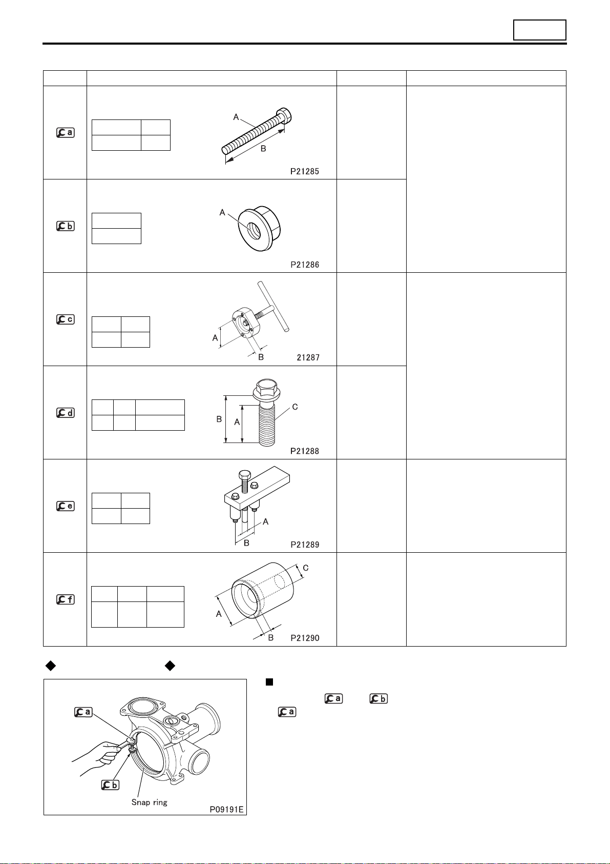
14
14-29
Special tools (Unit: mm)
Removal procedure
Removal: Snap ring
• Install the and into bolt hole of snap ring, then tighten
and remove the snap ring.
Mark Tool name and shape Part No. Application
MH001102
Removal and installation of snap ring
MF434103
MH062411
Removal of flange
MH000715
MH062192 Removal of impeller
MH062195 Installation of unit seal
Bolt
AB
M6
× 160
Nut
A
M6
× 1
Water pump pully
puller
AB
60 13
Bolt
AB C
26 35 M10
× 1.5
Impeller puller
AB
φ 10 48
Unit seal installer
AB C
φ 28
9.6
±
0.03
φ 12.5±
0.
1
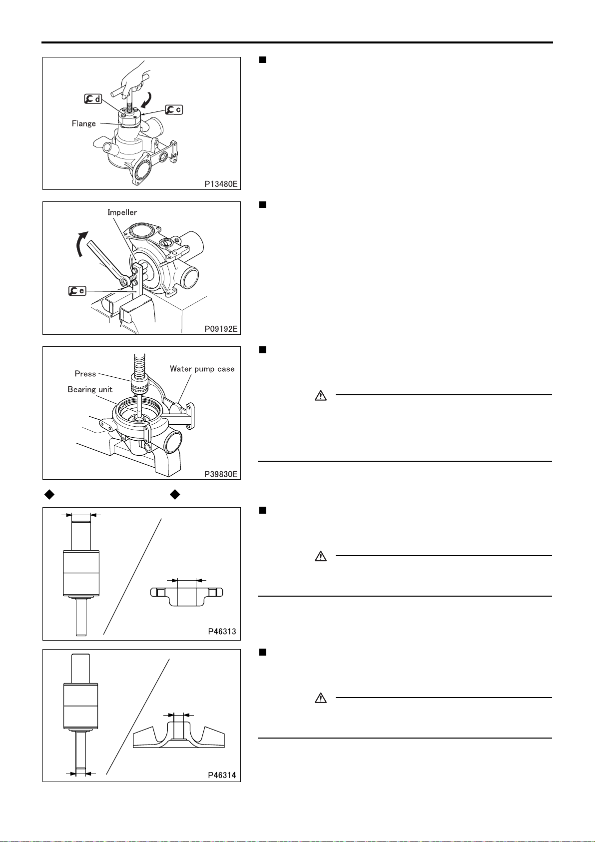
14-30
Removal: Flange
Removal: Impeller
Removal: Bearing unit
• Remove the bearing unit using a press. Heating the water pump
case to approximately 80°C will facilitate the removal.
CAUTION
• The ram load applied to remove the bearing unit should not
exceed 9800 N {1000 kgf}.
• When the bearing unit is replaced, always replace the unit
seal.
Inspection procedure
Inspection: Interference between flange and bearing unit
• If the measurement deviates from the standard value, replace
the defective part(s).
CAUTION
• Even if the measurement complies with the standard value,
reassembly must not be carried out more than twice.
Inspection: Interference between impeller and bearing unit
• If the measurement deviates from the standard value, replace
the defective part(s).
CAUTION
• Even if the measurement complies with the standard value,
reassembly must not be carried out more than twice.
WATER PUMP
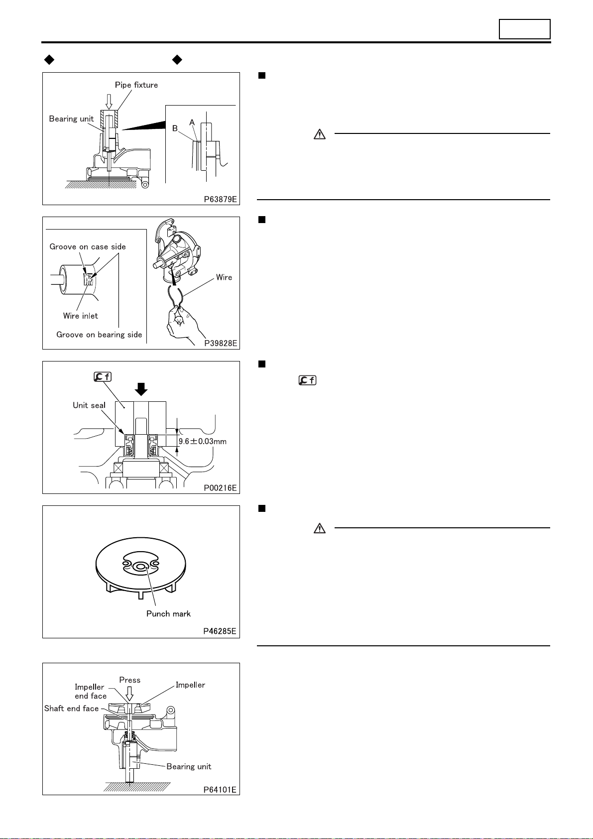
14
14-31
Installation procedure
Installation: Bearing unit
• Install the bearing unit by ramming down its outer race with the
press until the end face A of the outer race and the end face B of
water pump case meet flush.
CAUTION
• Before installing, check the rotating condition of the bear-
ing unit.
• When installing, do not press the shaft end of the bearing
unit.
Installation: Wire
• Align the groove on the water pump case side with the groove
on the bearing side at the wire inlet before inserting the wire into
the water pump case.
Installation: Unit seal
• Using , install the unit seal until it securely contacts the wa-
ter pump case.
Installation: Impeller
CAUTION
• Before installing an impeller, make sure that there is no or
only one punch mark in the shown location on the impeller.
Make an additional punch mark on the flange to indicate
that it undergoes the disassembly and reassembly process
you are doing now.
• Punch mark(s) indicate the number of times the impeller
was disassembled and reassembled in the past. If there are
two marks, the impeller must be replaced.
• With a press installed against the impeller end face, press fit the
impeller onto the bearing unit until the impeller end face is flush
with the shaft end face of the bearing unit.
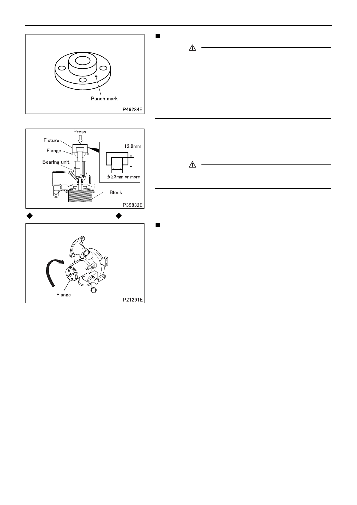
14-32
Installation: Flange
CAUTION
• Before installing a flange, make sure that there is no or only
one punch mark in the shown location on the flange. Make
an additional punch mark on the flange to indicate that it
undergoes the disassembly and reassembly process you
are doing now.
• Punch mark(s) indicate the number of times the flange was
disassembled and reassembled in the past. If there are two
marks, the flange must be replaced.
• Stand the shaft of the bearing unit on a block as illustrated.
• Place a fixture on the flange and apply the load of a press to it.
• Press the fixture down until the shaft of the bearing unit contacts
the fixture.
CAUTION
• If the flange is installed without the fixture, the water pump
case will be damaged.
Inspection after assembly
Inspection: Flange rotation
• Rotate the flange by hand. The flange should rotate smoothly
without any binding.
• If the flange does not rotate freely, disassemble and check.
WATER PUMP

M E M O
14-33
14
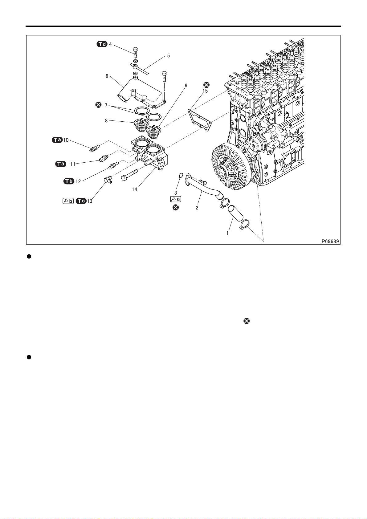
14-34
Disassembly sequence
• Do not remove the thermostat case unless it has a water leak or any other defect.
Installation sequence
Follow the disassembly sequence in reverse.
• Refer to the previous section “DISCONNECTION AND CONNECTION OF HOSES AND PIPES” for the correct
insertion depth of thermostat cover and case hoses into the pump as well as the correct tightening torque of
clamps.
1 Water hose
2 Bypass pipe
3 O-ring
4 Eyebolt
5 Air bleeding pipe
6 Thermostat cover
7 Rubber ring
8 Thermostat
(Valve opening temperature
82°C)
9 Thermostat
(Valve opening temperature
88°C)
10 Water temperature sensor
(for engine control)
11 Water temperature sensor
<for thermometer>
12 Overheat switch
13 Water joint
14 Thermostat case
15 Gasket
: Non-reusable parts
MITSUBISHI 6M70 THERMOSTAT
M
itsubishi 6M70 Engine Parts contact:
email: [email protected]
Phone: 269 673 1638
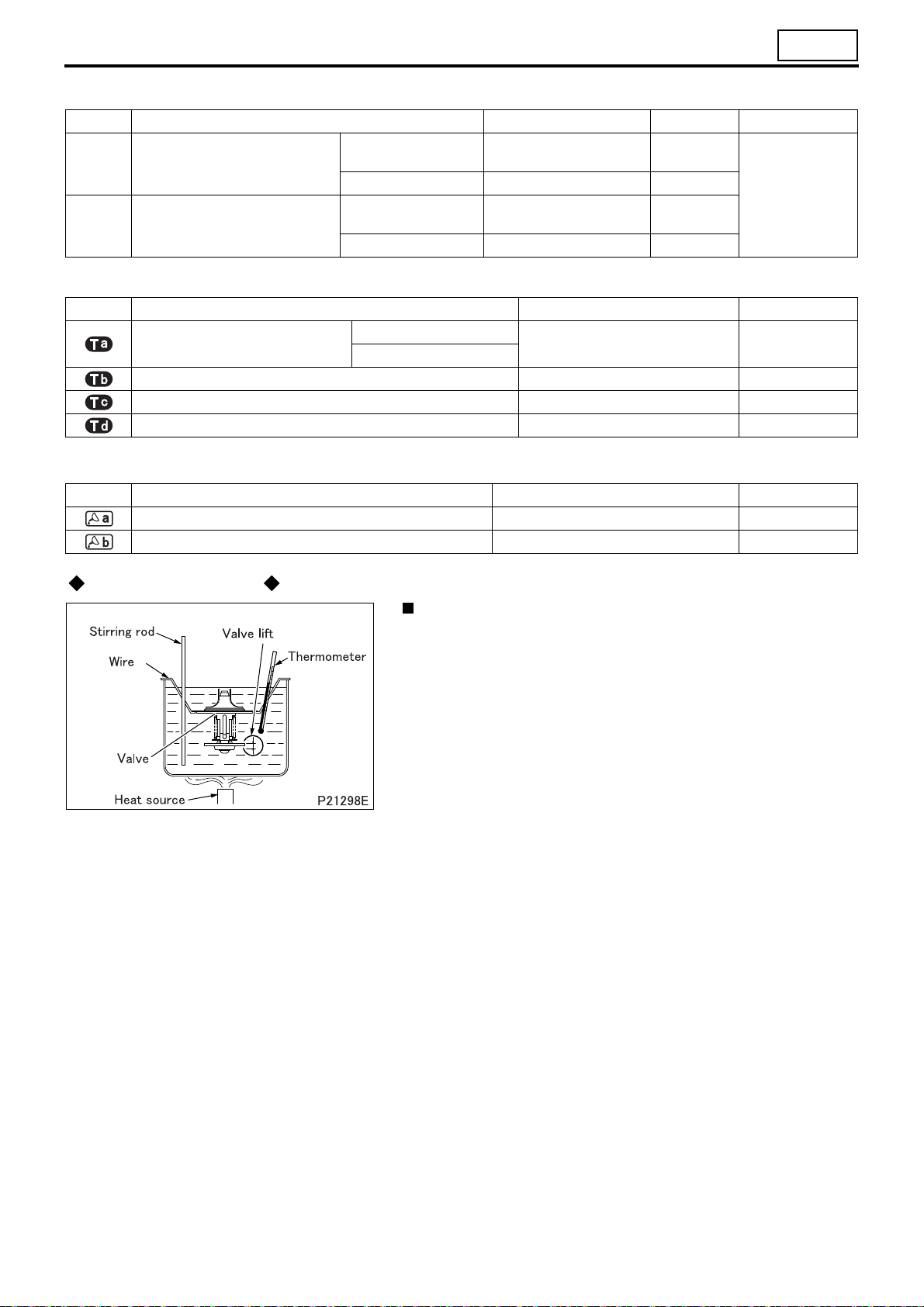
14
14-35
Service standards (Unit: mm)
Tightening torque (Unit: N·m {kgf·m})
Lubricant and/or sealant
Inspection procedure
Inspection: Thermostat
• Stir the water using a stirring rod to maintain an even water tem-
perature in the container, then conduct the tests indicated below.
• If the measurement deviates from the standard value, replace
the thermostat.
(1) Valve opening temperature
• Hold the thermostat with wire to keep it away from the heat
source.
• Heat the water gradually to the valve opening temperature.
• Maintain this temperature for five minutes and make sure that
the valve is completely open.
• Make sure that the valve closes completely when the water tem-
perature drops below 65°C.
(2) Valve lift
• Maintain the coolant temperature at the specified temperature
for five minutes to keep the valve fully open.
• Measure the valve lift.
Location Maintenance item Standard value Limit Remedy
8 Thermostat
Valve opening
temperature
82 ± 2°C–
Replace
Valve lift/temperature 10 or more/95°C–
9 Thermostat
Valve opening
temperature
88 ± 2°C–
Valve lift/temperature 10 or more/100°C–
Mark Parts to be tightened Tightening torque Remarks
Water temperature sensor
For engine control
39 {40} –
For thermometer
Overheat switch 27 to 41 {2.8 to 4.2} –
Water joint 34 {3.5} Sealant
Eyebolt 25 {2.6} –
Mark Points of application Specified lubricant and/or sealant Quantity
O-ring Engine oil As required
Winding around threaded portion of water joint Teflon tape 3.5 turns

15-1
GROUP 15 MITSUBISHI 6M70 INTAKE
AND EXHAUST
SPECIFICATIONS ................................ 15-2
STRUCTURE AND OPERATION
1. Air Cleaner ...................................... 15-3
2. Turbocharger .................................. 15-4
3. Turbocharger Control System ......... 15-5
4. Diesel Particulate Filter.................... 15-8
TROUBLESHOOTING ......................... 15-9
ON-VEHICLE INSPECTION AND ADJUST-
MENT
1. Measurement and Adjustment of
Turbocharger Boost Pressure .......
15-10
2. Cleaning and Inspection of
Air Cleaner Element
...................... 15-12
3. Check for Looseness in Intake
Manifold Mounting Bolts and
Nuts
.............................................. 15-12
4. Check for Cracks and Gas
Leakage in Exhaust Manifold
........ 15-12
5. Check for Cracks and Gas
Leakage in Turbocharger
.............. 15-12
TURBOCHARGER CONTROL SYSTEM
1. Diagnosis Procedure ..................... 15-14
2. Diagnostic Precautions ................. 15-14
3. Inspections Based on
Diagnosis Codes
.......................... 15-15
4. Multi-Use Tester
Service Data
................................. 15-20
5. Actuator Tests by
Multi-Use Tester
............................ 15-20
6. Inspection of
Electrical Equipment
..................... 15-21
7. Installed Locations of Parts .......... 15-22
8. Electric Circuit Diagram ................ 15-30
AIR CLEANER ................................... 15-34
TURBOCHARGER ............................... 15-36
INTERCOOLER ................................... 15-48
INTAKE MANIFOLD............................ 15-50
EXHAUST MANIFOLD........................ 15-52
EXHAUST PIPE
<FS>...................................................... 15-54
<EXCEPT FS>....................................... 15-56
DIESEL PARTICULATE FILTER
<FS>................................................... 15-58
<EXCEPT FS> .................................... 15-60

15-2
/
Item Specifications
Air cleaner element Cyclone filter paper type
Dust indicator type Mechanical
Turbocharger
Model
TF08
(VG (Variable Geometry: Variable nozzle vane
type) Turbocharger)
Manufacturer Mitsubishi Heavy Industries
Intercooler type Tube and corrugated fin (air cooled)
DPF (Diesel Particulate Filter) Continuous regeneration type
SPECIFICATIONS
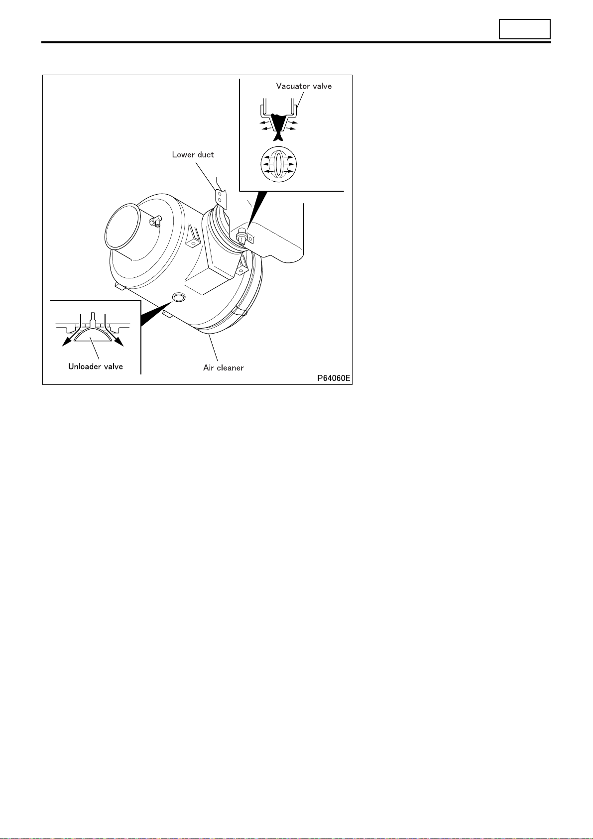
15
15-3
1. Air Cleaner
• The air cleaner is a single element
type.
• The air cleaner is provided with an un-
loader valve and a vacuator valve.
• When the engine speed drops below a
specified level, the vacuator and un-
loader valves are shaken by a conse-
quent change in internal vacuum to
automatically force out accumulated
water and dust.
STRUCTURE AND OPERATION
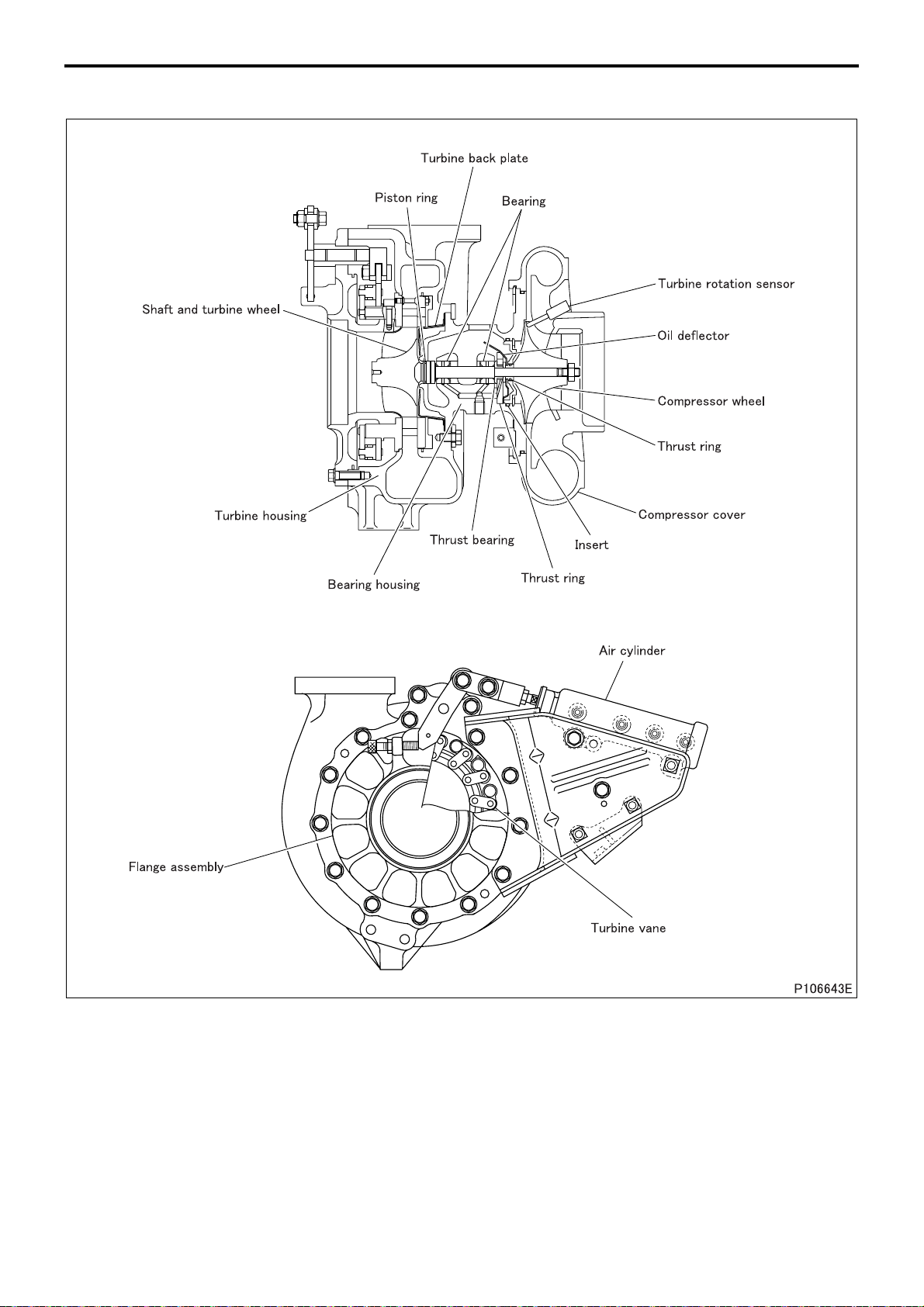
15-4
2. Mitsubishi 6M70 Turbocharger
• TF08 model is equipped with turbocharger, which is a variable nozzle vane type turbocharger with adjustable,
heat-resistive alloy turbine vanes provided at the turbine exhaust gas inlet port.
STRUCTURE AND OPERATION
M
itsubishi 6M70 Engine Parts contact:
email: [email protected]
Phone: 269 673 1638
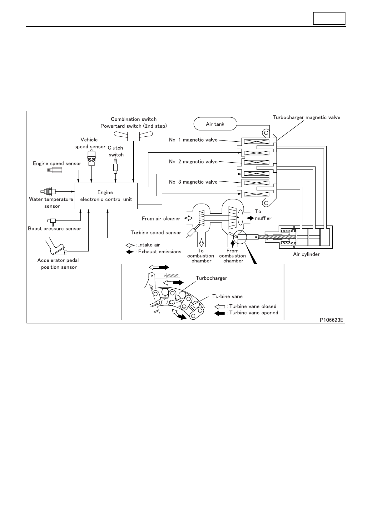
15
15-5
3. Turbocharger Control System
3.1 General description
• The turbocharger control system uses various sensors to detect the status of the engine and controls the turbo-
charger magnetic valves according to sensor output data by means of the engine electronic control unit.
• The turbocharger magnetic valves control the air cylinder movement to optimize the opening of the turbine vanes
according to operating conditions.
• When powertard brake (2nd step) is activated, the turbine vanes are closed, the turbocharger speed is increased
and more air is supplied to the combustion chamber.
15-6
3.2 Electronic Control System
(1) System block diagram
Starter switch (S)
Water temperature sensor
Accelerator pedal position sensor
Clutch switch
Engine speed sensor
Boost pressure sensor
Powertard switch (2nd stage)
Turbine speed sensor
Input signals
Turbocharger control
function
Diagnosis function
Turbocharger magnetic
valve
Engine warning lamp
Engine-electronic control unit
Output signals
Vehicle speed sensor
Diagnosis switch
Memory clear switch
STRUCTURE AND OPERATION
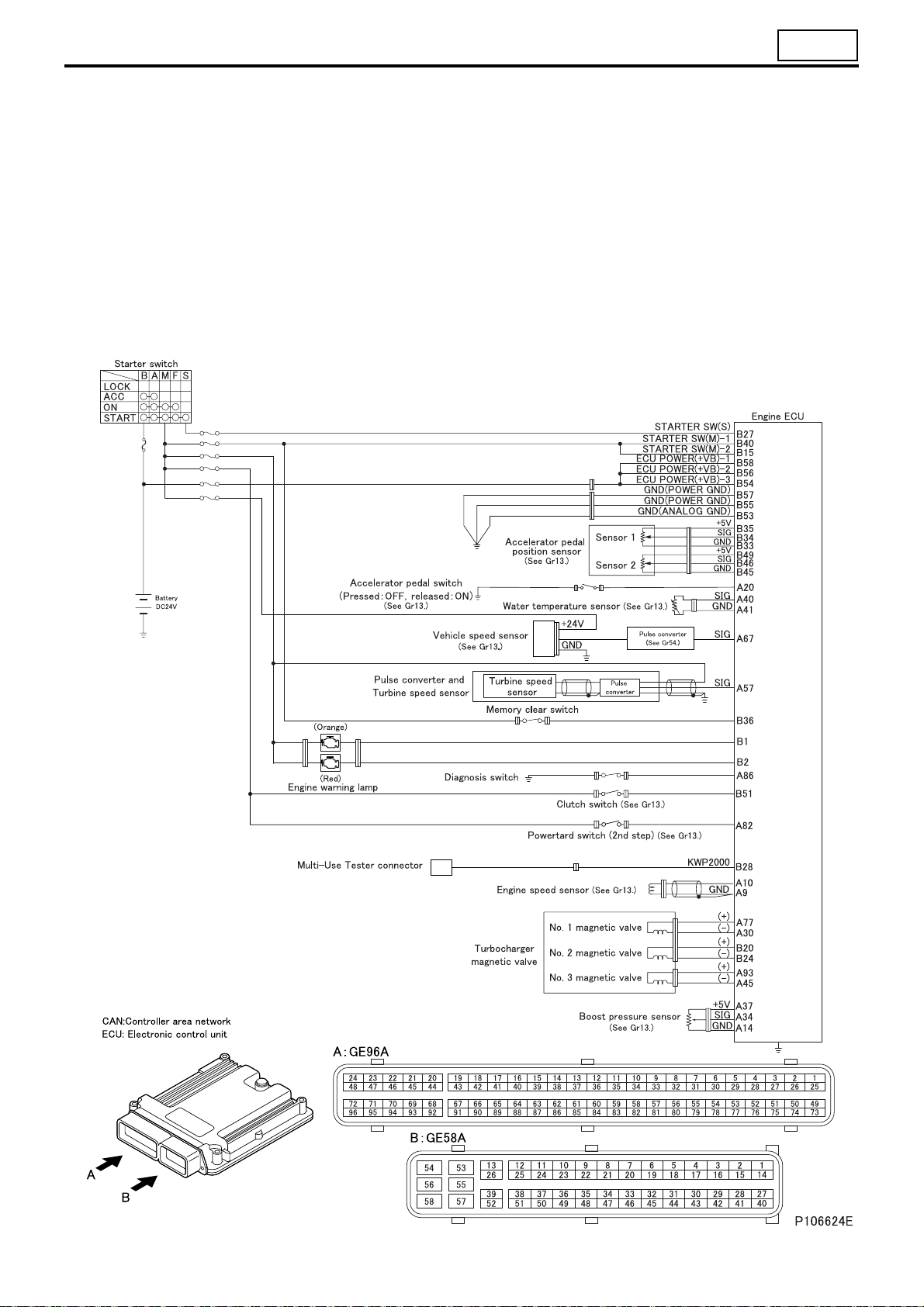
15
15-7
(2) Diagnosis function
• While the starter switch is on, the diagnosis function is constantly activated to find faults in various sensors. Upon
any sensor being found faulty, the driver is informed of the fault through the display in the meter cluster. At the
same time, the fault is memorized in the form of a diagnosis code and the system starts to effect necessary at-
fault control(s).
• During at-fault control(s), the system is limited in the workings to ensure the safety of the vehicle and driver. The
memorized diagnosis code can be accessed on the Multi-Use Tester screen or through blinking of warning lamp.
• Diagnosis codes are different in the way of indication between the Multi-Use Tester and blinking of the warning
lamp.
• The Multi-Use Tester provides more specific diagnosis codes.
3.3 Electronic control unit connection diagram
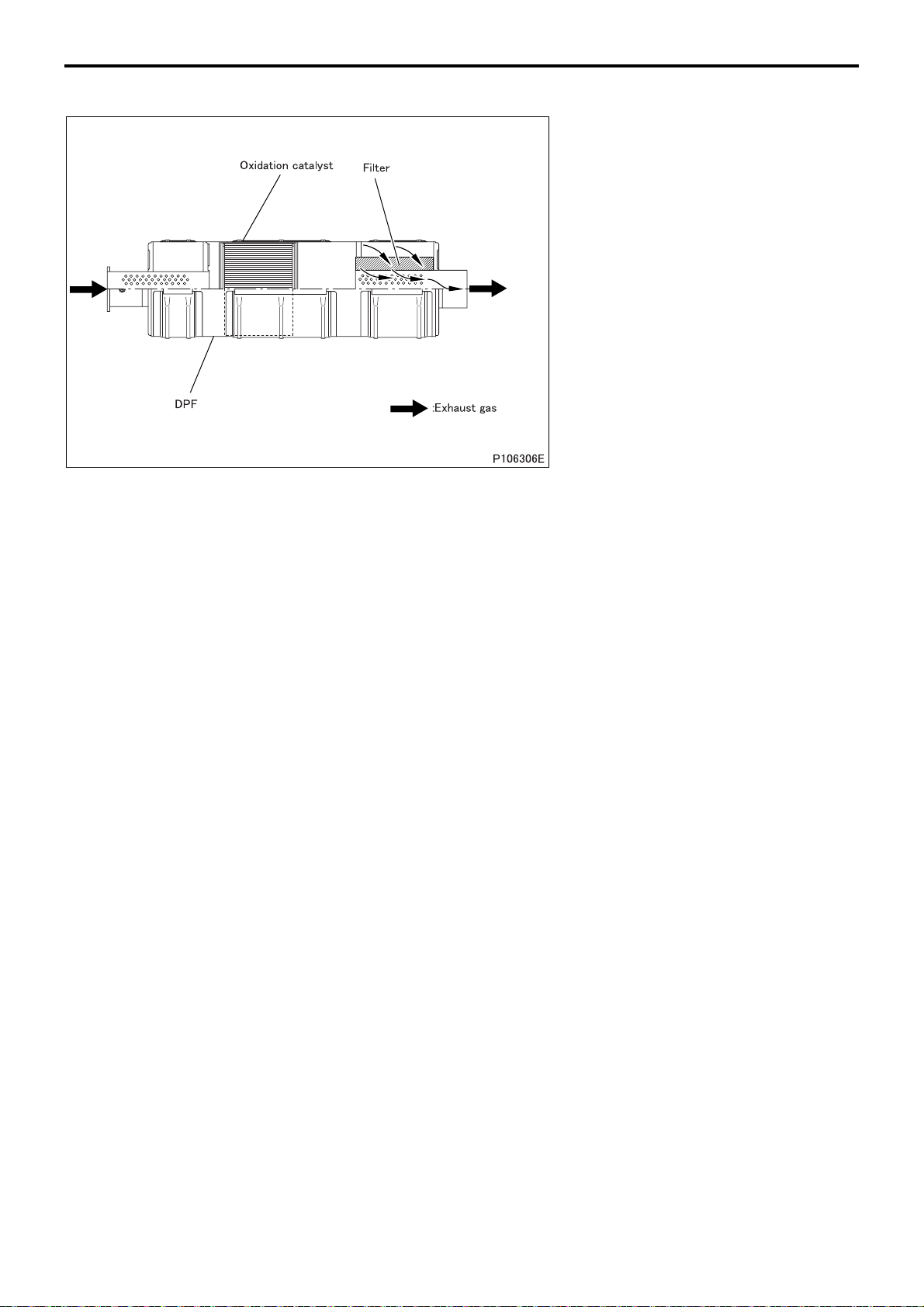
15-8
4. Diesel Particulate Filter
• Diesel particulate filter is a large-ca-
pacity system consisting of an ultra-ef-
ficient oxidation catalyst and a filter.
Diesel particulate filter is designed to
efficiently break and capture PM emit-
ted by engines running on low-sulfur
fuel, and the filter is continuously re-
generated.
• The new environmentally-friendly en-
gine has drastically-reduced PM emis-
sion levels. In addition, the ultra-
efficient oxidation catalyst breaks and
treats most of PM emitted from the en-
gine, minimizing PM loading/deposit
onto the subsequent filter. As a result,
the filter is unlikely to clog up even un-
der the driving conditions that require
long hours of drive with relatively low
exhaust gas temperature. Also, active
regeneration, which increases fuel
consumption, is not required.
• The size of the filtration openings has
been optimized to eliminate the de-
posit of ash (product of combustion)
generated in the engine. The filter re-
quires no maintenance, including peri-
odical cleaning.
STRUCTURE AND OPERATION
15
15-9
Symptoms
Engine hard to start
Black exhaust gas
White exhaust gas
Poor engine power
Excess oil consumption
Abnormal noise or vibration in intake/exhaust
system
Reference Gr
Possible causes
Air cleaner Clogged air cleaner element O O O O
Turbocharger
Cartridge assembly
Defective bearing O O O
Carbon deposits on shaft and turbine wheel
unit
OO
Interference between shaft and turbine
wheel unit and turbine back plate
OO O
Interference between shaft and turbine
wheel unit and turbine housing
OO O
Bent shaft and turbine wheel unit O O O
Damaged shaft and turbine wheel unit O O O
Interference between compressor wheel
and compressor cover
OO O
Seized thrust sleeve and/or thrust bearing O O O
Damaged compressor wheel O O O
Oil leakage due to worn piston ring and/or
insert
OO O
Piston ring fitted poorly O
Defective sliding action between parts due
to clogged lubrication oil pipe and eyebolt
OO O
Oil seals damaged due to clogged oil return
pipe
OO
Compressor cover fitted poorly O O O O
Turbine housing fitted poorly O O
Intercooler
Foreign substances deposited on intercooler front
core
O
Front pipe/DPF/tail pipe deformed O O
Front pipe/DPF/tail pipe fitted poorly O O
Incorrect valve clearances O
Gr11
Head gasket defective O
Wear/carbon deposits on valves and valve seats O
Valve spring weakened O
Piston rings worn/damaged O O
Piston ring grooves worn/damaged O O
Cooling system malfunctioning O Gr14
Engine oil quantity excessive O Gr12
Major moving parts seized O O Gr11
Uneven or excessive fuel injection O Gr13
TROUBLESHOOTING
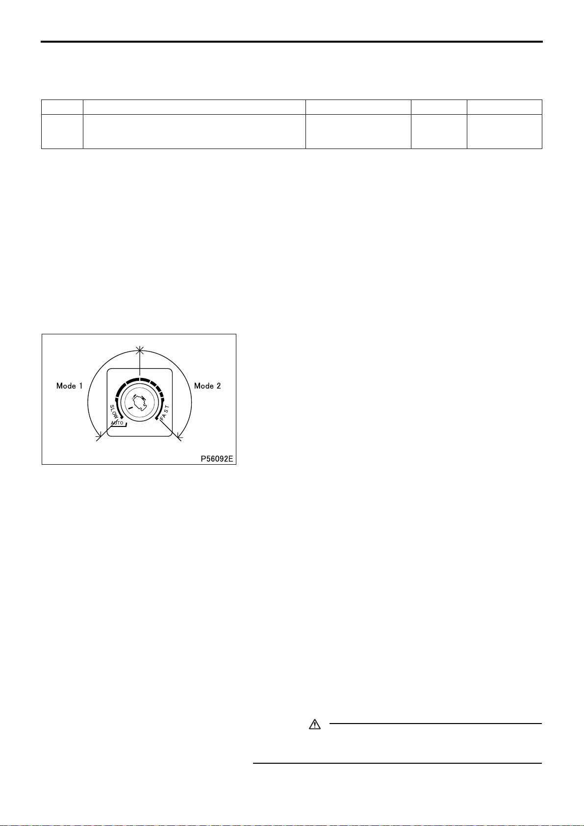
15-10
1. Measurement and Adjustment of Turbocharger Boost Pressure
Service standards
(1) Preparation
• Put the transmission in N range.
• Turn the steering wheel in neutral position.
• Turn off all lamps and accessories.
• Connect the Multi-Use Tester.
• Check diagnosis code of each electronic control system. If any
fault exists, rectify it.
• Warm up the engine until the engine coolant has been heated to
more than 60°C. (verify from Service Data “2E: Water Tempera-
ture”)
• Check that the non-load minimum speed (idling speed) is as
specified. (See Gr13.)
(2) Measurement and correction of boost pressure
• Turn the idle adjust dial to any position within the illustrated
range of Mode 1.
• Select [Engine Control] on the system select screen of the Multi-
Use Tester, then execute [BA: VGT Test] from [Actuator Tests].
• When [BA: VGT Test] is executed, the engine speed should be
automatically increased to 1600 rpm (No. 2 magnetic valve acti-
vated).
• Maintain the state of [BA: VGT Test] having been executed (for 5
to 15 minutes) until boost pressure is stabilized.
• Measure the following items from among [Service Data].
26: Boost pressure (actual boost pressure)
2B: Intake air temperature (actual intake air temperature)
30: Atmospheric pressure (actual atmospheric pressure)
• Obtain corrected boost pressure by calculating above Service
Data.
[Correction with intake air temperature]
Corrected boost pressure [kPa] = Measured boost pressure + 0.43
(measured intake air temperature - 25)
[Correction with boost temperature (Exhaust gas recirculation
temperature)]
Corrected boost pressure [kPa] = Measured boost pressure + 0.02
(measured boost temperature - 33)
[Correction with atmospheric pressure]
Corrected boost pressure [kPa] = Measured boost pressure -
(measured atmospheric pressure - 101.5)
• If corrected boost pressure in any case above deviates from the
standard value, adjust the turbocharger.
CAUTION
• If the adjusting range of the air cylinder shaft exceeds ±1.5
turns, check the turbocharger.
Location Maintenance item Standard value Limit Remedy
–
Boost pressure
(when VGT test performed with ambient temperature at
25°C and atmospheric pressure at 101.5 kPa)
157 ± 7 kPa – Adjust
ON-VEHICLE INSPECTION AND ADJUSTMENT
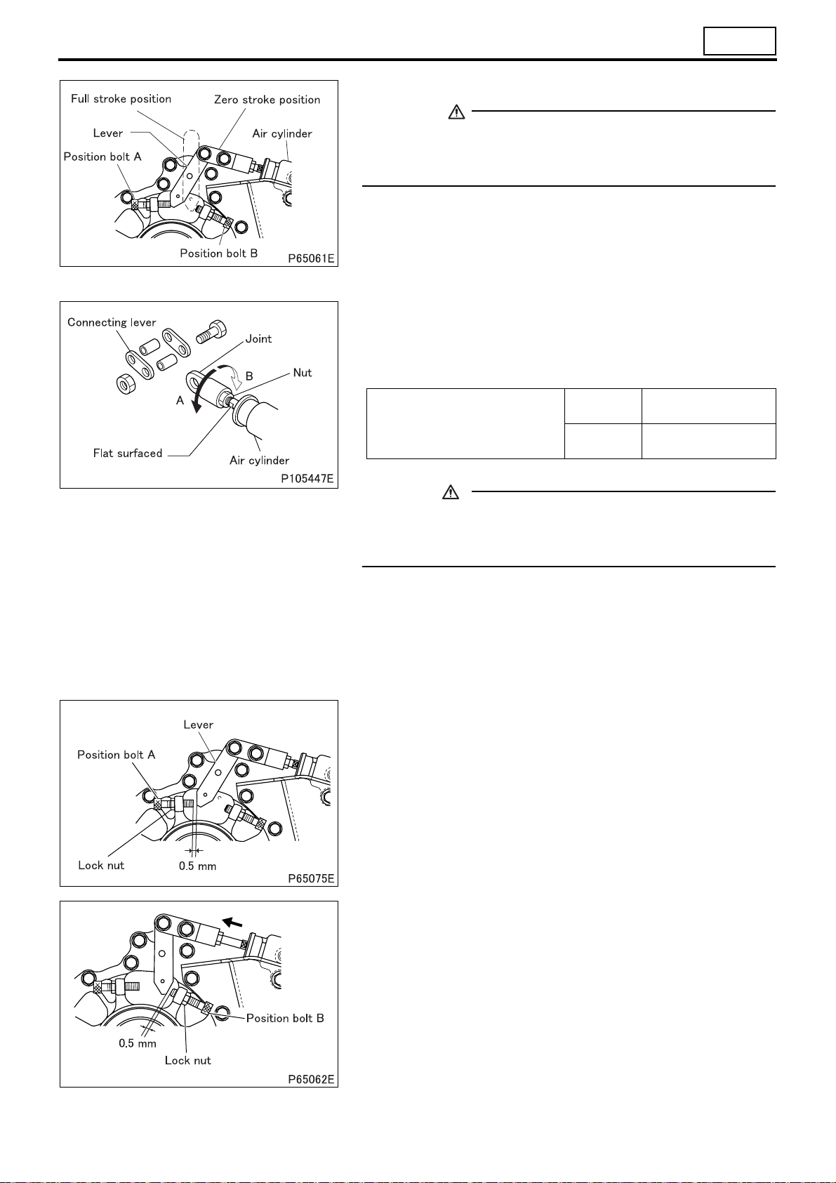
15
15-11
(3) Adjustment of turbocharger
WARNING
• The turbocharger is hot for a while after the engine is
stopped. Take care not to burn yourself during adjustment
work.
• To adjust the turbocharger, turn the joint.
• Make sure that the air cylinder is in the state of zero stroke when
the engine is stopped.
• Loosen the position bolts A and B.
• Remove the connecting levers from the air cylinder joint.
• With a wrench put on the flats of the air cylinder shaft, loosen the
nu
t.
• Turning the joint part of the air cylinder, adjust the length of the
shaft.
CAUTION
• If boost pressure exceeds the standard value, the engine
may malfunction or break down. Boost pressure must be
within the specified range.
• After adjustment, secure the shaft with nut and refit the levers to
the joint.
• Measure boost pressure again.
• If the boost pressure deviates from the standard value, readjust
it.
• Make sure that the air cylinder is in the state of zero stroke when
the engine is stopped.
• Tighten the position bolt A for the illustrated clearance between
the bolt and lever.
• After adjustment, secure the bolt with the lock nut.
• Introduce specified pressure in the air cylinder from the port A,
B, C to bring the air cylinder into the state of full stroke.
• Tighten the position bolt B for the illustrated clearance between
the bolt and lever.
• After adjustment, secure the bolt with the lock nut.
Adjusting guide: One turn
(with engine speed at 1600 rpm)
Direction A
Decreased by ap-
prox. 17 kPa
Direction B
Increased by approx.
17 kPa
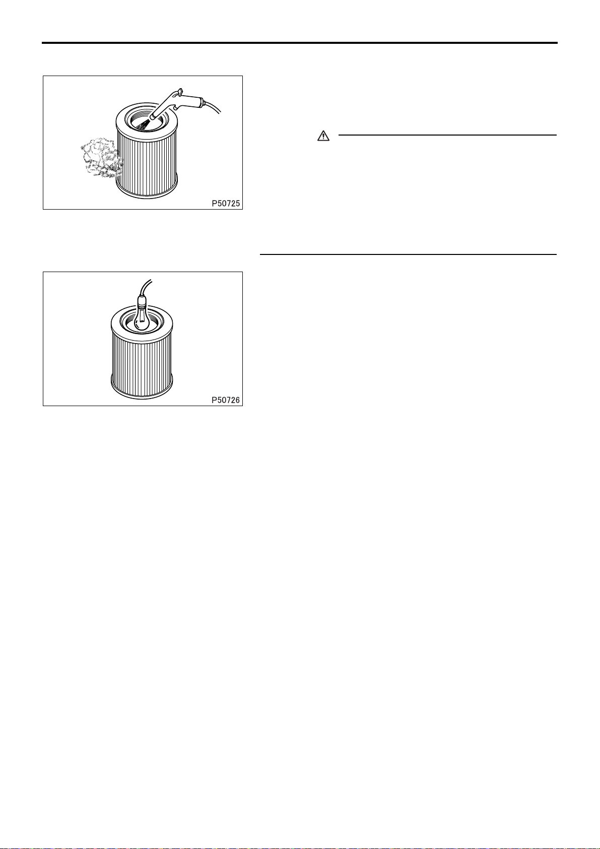
15-12
2. Cleaning and Inspection of Air Cleaner Element
[Cleaning: Element]
• Blow a jet of compressed air at a pressure not higher than 685
kPa {7 kgf/cm
2
} against the inside surfaces of the element.
CAUTION
• For the frequency and timing of cleaning, refer to the rele-
vant instruction manual. More frequent cleaning than nec-
essary could damage the element or cause dust and foreign
matter to be sucked into the engine.
• Do not strike the element or hit it against another object to
remove dust.
• Do not blow compressed air against outside surfaces of the
element.
[Inspection: Element]
• Shine some electric light inside the element.
• Replace the element if thin spots or broken parts are evident in
the filter paper, or if the packing at the top of the element is dam-
aged.
Also replace the element if the dust on the element is damp with
oily smoke or soot, regardless of the replacement schedule.
3. Check for Looseness in Intake Manifold Mounting Bolts and Nuts
• Check for looseness in the intake manifold and air inlet pipe mounting bolts and nuts. If there is looseness, tighten
the bolts and nuts to the specified torque. (See “INTAKE MANIFOLD”.)
4. Check for Cracks and Gas Leakage in Exhaust Manifold
• Inspect the exhaust manifold visually. If there is any trace of gas leakage or cracks, replace the exhaust manifold.
(See “EXHAUST MANIFOLD”.)
• Check for looseness in the exhaust manifold mounting nuts. If there is looseness, tighten the nuts to the specified
torque. (See “EXHAUST MANIFOLD”.)
5. Check for Cracks and Gas Leakage in Turbocharger
• Inspect the turbocharger visually. If there is any trace of gas leakage or cracks, replace the turbocharger. (See
“TURBOCHARGER”.)
• Check for looseness in the turbocharger mounting bolts and nuts. If there is looseness, tighten the bolts and nuts
to the specified torque. (See “TURBOCHARGER”.)
ON-VEHICLE INSPECTION AND ADJUSTMENT

M E M O
15-13
15
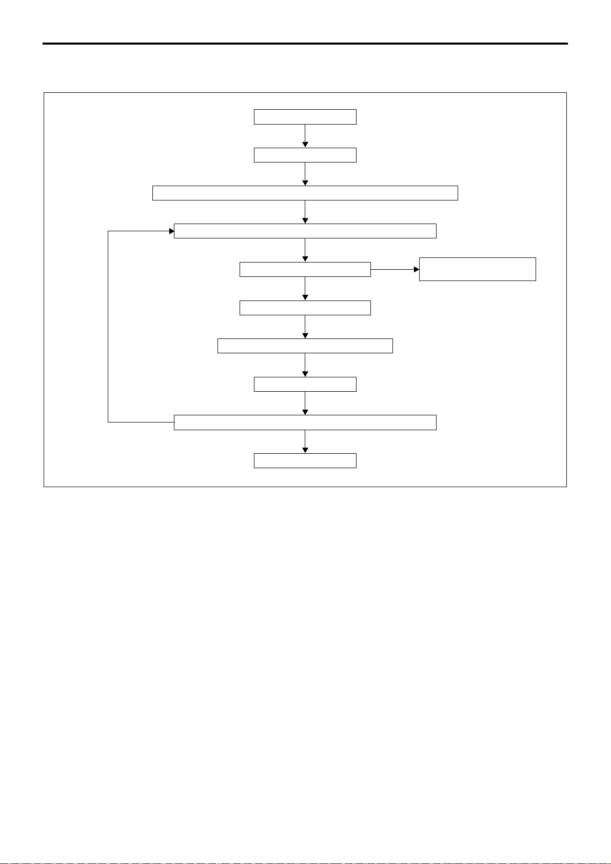
15-14
1. Diagnosis Procedure
• Perform the inspection in accordance with the following flowchart.
2. Diagnostic Precautions
• Before measuring voltage, check the battery for charged condition and specific gravity. If system inspection is per-
formed with the battery uncharged or reduced in specific gravity, accurate measurements cannot be achieved.
• Before disconnecting battery cables, harnesses and connectors, set the starter switch to LOCK or OFF, then allow
at least 20 seconds.
• To avoid having electrical parts damaged, set the starter switch and lighting switch to LOCK or OFF before recon-
necting battery cables, harnesses and connectors.
• When performing measurement with the tester, handle the test bar carefully so that it does not damage internal
circuit and other electrical parts of the electronic control unit to result in a short-circuit failure between terminals in
connector or between connector and car body
.
• Re
sistance is affected by temperature. Determine the necessity of resistance measurement following given tem-
perature specification as a guide. Otherwise, use normal temperature (10 to 35°C) as the measuring condition.
Vehicle in service shop
Read all (past and present) diagnosis codes by Multi-Use Tester. (See Gr00.)
Warning lamp lit
Was able to identify the fault?
Response to transient fault
(See Gr00.)
Perform inspection based on diagnosis codes. (See later section.)
Rectify or replace with new parts.
Clear stored diagnosis code. (See Gr00.)
Read diagnosis code(s) by Multi-Use Tester. (See Gr00.)
Code issued
End of inspection
Tes t d r i v e
NO
YES
No code issued
TURBOCHARGER CONTROL SYSTEM
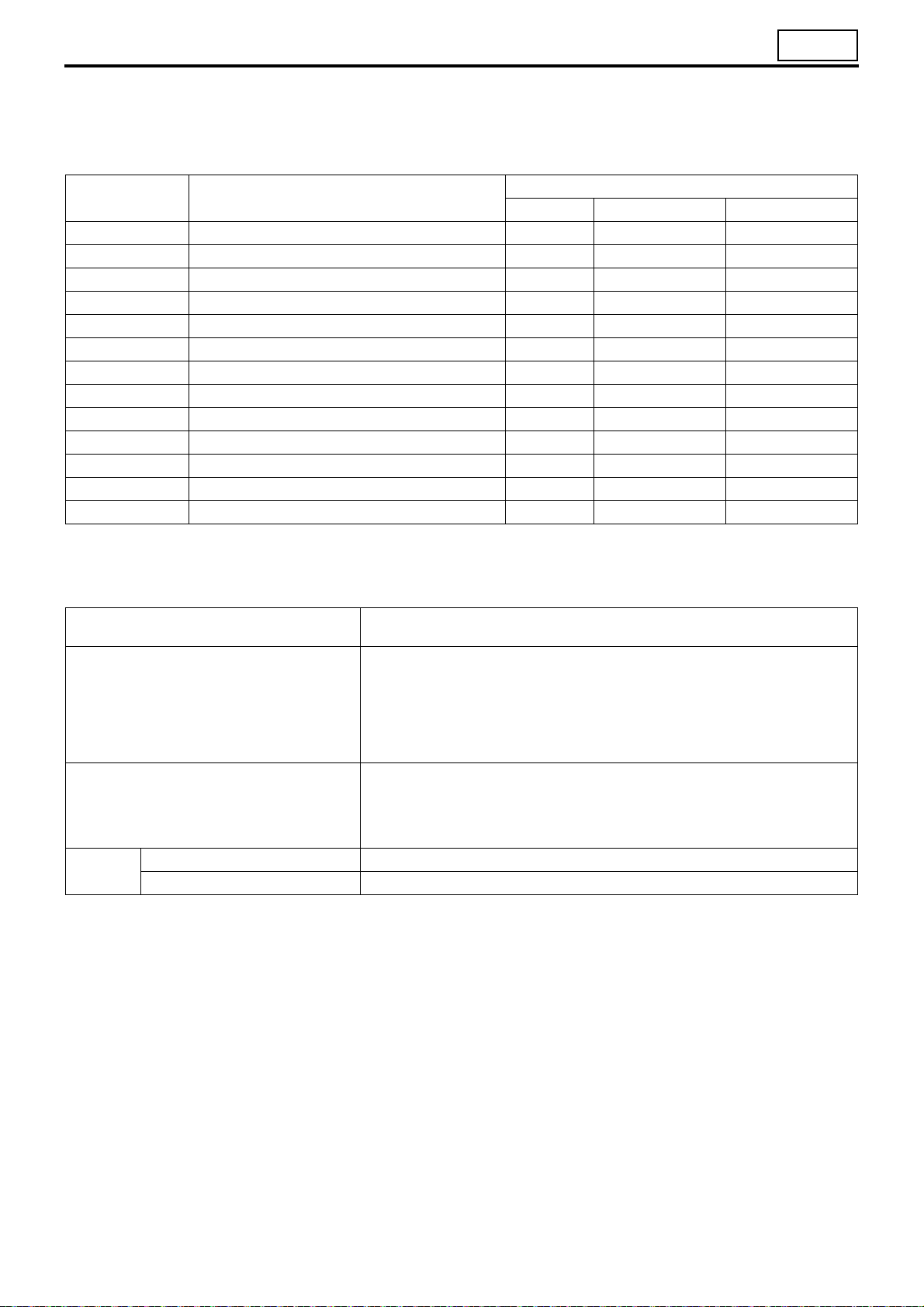
15
15-15
3. Inspections Based on Diagnosis Codes
3.1 Diagnosis code list
• Diagnosis codes shown by the Multi-Use Tester and those indicated by flashing of the warning lamp are different.
• The Multi-Use Tester is capable of showing more detailed diagnosis codes.
3.2 Diagnosis code generation conditions and inspection items
P0234: Over Boost (warning lamp flashes: 54)
Code Message
Warning lamp indication
Flashes Red Orange
P0234 Over Boost 54 – O
P1130 VGT1 51 – O
P1132 VGT1 51 – O
P1133 VGT1 51 – O
P1135 VGT2 52 – O
P1137 VGT2 52 – O
P1138 VGT2 52 – O
P1140 VGT3 53 – O
P1142 VGT3 53 – O
P1143 VGT3 53 – O
P1236 Turbine Revolution SNSR (Low) 57 – O
P1237 Turbine Revolution SNSR (High) 57 – O
P1238 Turbine Overrunning 59 – O
Generation condition
Boost pressure remaining above the specified value for 10 seconds is repeated
five times when engine speed is at 600 rpm up to 2300 rpm.
Recoverability
• In the case of above problem
• System recovers if boost pressure is below the specified value when en-
gine speed is at 600 rpm up to 2300 rpm.
• In the case where above problem is repeated five more times
• System recovers (power is re-supplied to electronic control unit) if signal
becomes normal when starter switch is turned OFF (2 minutes or more)
→ ON.
Control effected by electronic control unit
• In the case of above problem
• No specific control is effected.
• In the case where above problem is repeated five more times
• Injection quantity is limited. (Output is reduced, and exhaust emissions
worsen.)
Inspection
Service data 26: Boost Pressure
Other Turbocharger
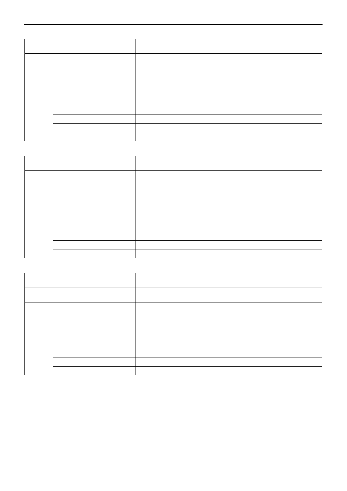
15-16
P1130: VGT1 (warning lamp flashes: 51)
P1132: VGT1 (warning lamp flashes: 51)
P1133: VGT1 (warning lamp flashes: 51)
Generation condition
Current flowing in the turbocharger magnetic valve (No. 1 magnetic valve) re-
mains above the specified value for 1 second.
Recoverability
System recovers when current flowing in the turbocharger magnetic valve (No.
1 magnetic valve) becomes normal for 1 second.
Control effected by electronic control unit
• Turbocharger control is stopped.
• Exhaust gas recirculation control is stopped.
• Auto cruise control is stopped.
• Injection quantity is limited. (Output is reduced, and exhaust emissions wors-
en.)
• Actuator test “BA: VGT Test” is stopped.
Inspection
Service data 21: VGT position, 82: VGT M/V1
Actuator test A9: VGT1
Electrical equipment #566: Turbocharger magnetic valve
Electric circuit diagram Turbocharger magnetic valve (No. 1 magnetic valve) system
Generation condition
Turbocharger magnetic valve (No. 1 magnetic valve) circuit shorted to ground
or open-circuited (low level when turned OFF) as detected for 1 second.
Recoverability
System recovers when current flowing in the turbocharger magnetic valve (No.
1 magnetic valve) becomes normal (high level when turned OFF) for 1 second.
Control effected by electronic control unit
• Turbocharger control is stopped.
• Exhaust gas recirculation control is stopped.
• Auto cruise control is stopped.
• Injection quantity is limited. (Output is reduced, and exhaust emissions wors-
en.)
• Actuator test “BA: VGT Test” is stopped.
Inspection
Service data 21: VGT position, 82: VGT M/V1
Actuator test A9: VGT1
Electrical equipment #566: Turbocharger magnetic valve
Electric circuit diagram Turbocharger magnetic valve (No. 1 magnetic valve) system
Generation condition
Turbocharger magnetic valve (No. 1 magnetic valve) circuit shorted to battery
(high level when turned ON) as detected for 1 second.
Recoverability
System recovers when current flowing in the turbocharger magnetic valve (No.
1 magnetic valve) becomes normal (low level when turned ON) for 1 second.
Control effected by electronic control unit
• Turbocharger control is stopped.
• Exhaust gas recirculation control is stopped.
• Auto cruise control is stopped.
• Injection quantity is limited. (Output is reduced, and exhaust emissions wors-
en.)
• Actuator test “BA: VGT Test” is stopped.
Inspection
Service data 21: VGT position, 82: VGT M/V1
Actuator test A9: VGT1
Electrical equipment #566: Turbocharger magnetic valve
Electric circuit diagram Turbocharger magnetic valve (No. 1 magnetic valve) system
TURBOCHARGER CONTROL SYSTEM
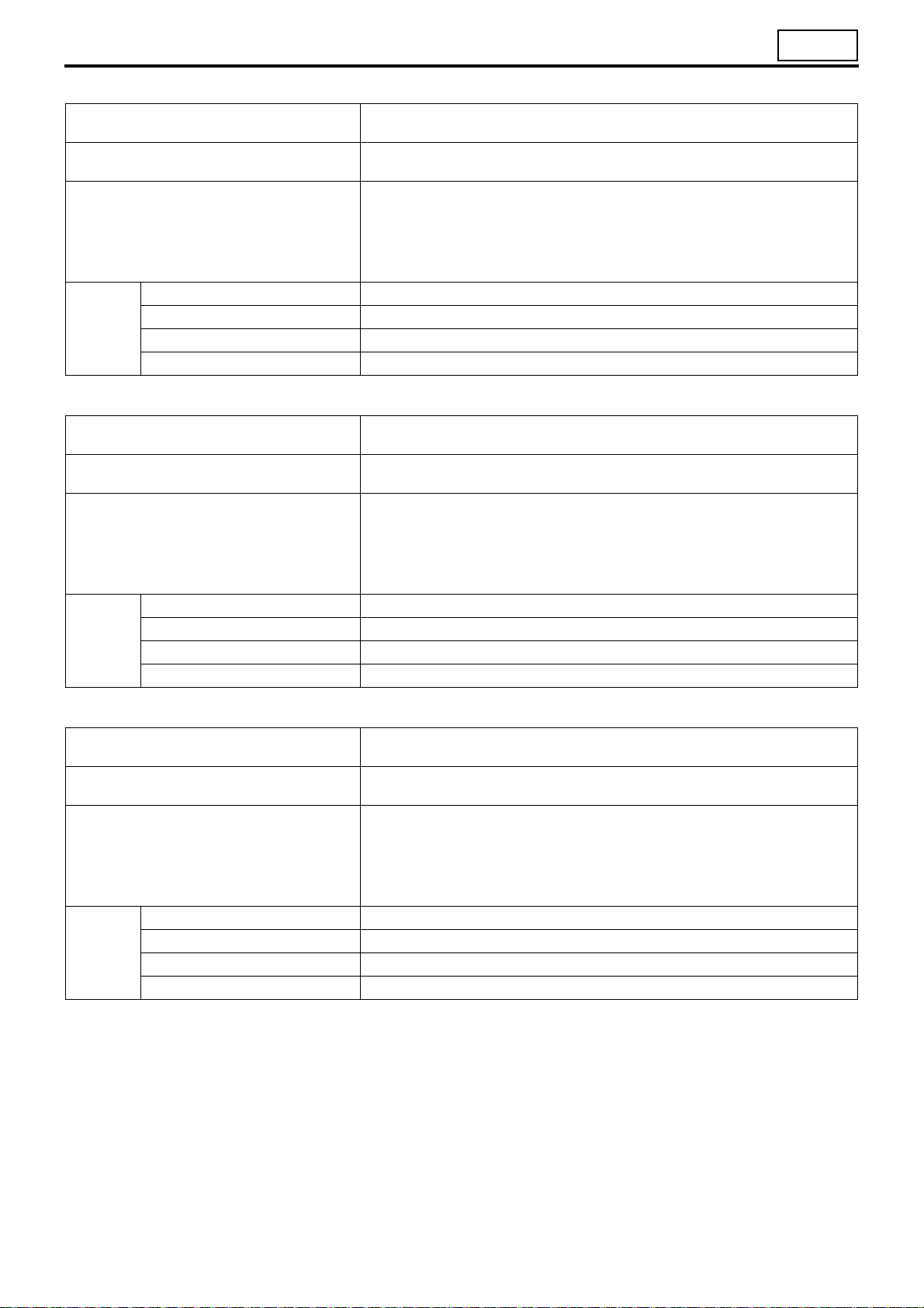
15
15-17
P1135: VGT2 (warning lamp flashes: 52)
P1137: VGT2 (warning lamp flashes: 52)
P1138: VGT2 (warning lamp flashes: 52)
Generation condition
Current flowing in the turbocharger magnetic valve (No. 2 magnetic valve) re-
mains above the specified value for 1 second.
Recoverability
System recovers when current flowing in the turbocharger magnetic valve (No.
2 magnetic valve) becomes normal for 1 second.
Control effected by electronic control unit
• Turbocharger control is stopped.
• Exhaust gas recirculation control is stopped.
• Auto cruise control is stopped.
• Injection quantity is limited. (Output is reduced, and exhaust emissions wors-
en.)
• Actuator test “BA: VGT Test” is stopped.
Inspection
Service data 21: VGT position, 83: VGT M/V2
Actuator test AA: VGT2
Electrical equipment #566: Turbocharger magnetic valve
Electric circuit diagram Turbocharger magnetic valve (No. 2 magnetic valve) system
Generation condition
Turbocharger magnetic valve (No. 2 magnetic valve) circuit shorted to ground
or open-circuited (low level when turned OFF) as detected for 1 second.
Recoverability
System recovers when current flowing in the turbocharger magnetic valve (No.
2 magnetic valve) becomes normal (high level when turned OFF) for 1 second.
Control effected by electronic control unit
• Turbocharger control is stopped.
• Exhaust gas recirculation control is stopped.
• Auto cruise control is stopped.
• Injection quantity is limited. (Output is reduced, and exhaust emissions wors-
en.)
• Actuator test “BA: VGT Test” is stopped.
Inspection
Service data 21: VGT position, 83: VGT M/V2
Actuator test AA: VGT2
Electrical equipment #566: Turbocharger magnetic valve
Electric circuit diagram Turbocharger magnetic valve (No. 2 magnetic valve) system
Generation condition
Turbocharger magnetic valve (No. 2 magnetic valve) circuit shorted to battery
(high level when turned ON) as detected for 1 second.
Recoverability
System recovers when current flowing in the turbocharger magnetic valve (No.
2 magnetic valve) becomes normal (low level when turned ON) for 1 second.
Control effected by electronic control unit
• Turbocharger control is stopped.
• Exhaust gas recirculation control is stopped.
• Auto cruise control is stopped.
• Injection quantity is limited. (Output is reduced, and exhaust emissions wors-
en.)
• Actuator test “BA: VGT Test” is stopped.
Inspection
Service data 21: VGT position, 83: VGT M/V2
Actuator test AA: VGT2
Electrical equipment #566: Turbocharger magnetic valve
Electric circuit diagram Turbocharger magnetic valve (No. 2 magnetic valve) system

15-18
P1140: VGT3 (warning lamp flashes: 53)
P1142: VGT3 (warning lamp flashes: 53)
P1143: VGT3 (warning lamp flashes: 53)
Generation condition
Current flowing in the turbocharger magnetic valve (No. 3 magnetic valve) re-
mains above the specified value for 1 second.
Recoverability
System recovers when current flowing in the turbocharger magnetic valve (No.
3 magnetic valve) becomes normal for 1 second.
Control effected by electronic control unit
• Turbocharger control is stopped.
• Exhaust gas recirculation control is stopped.
• Auto cruise control is stopped.
• Injection quantity is limited. (Output is reduced, and exhaust emissions wors-
en.)
• Actuator test “BA: VGT Test” is stopped.
Inspection
Service data 21: VGT position, 84: VGT M/V3
Actuator test AB: VGT3
Electrical equipment #566: Turbocharger magnetic valve
Electric circuit diagram Turbocharger magnetic valve (No. 3 magnetic valve) system
Generation condition
Turbocharger magnetic valve (No. 3 magnetic valve) circuit shorted to ground
or open-circuited (low level when turned OFF) as detected for 1 second.
Recoverability
System recovers when current flowing in the turbocharger magnetic valve (No.
3 magnetic valve) becomes normal (high level when turned OFF) for 1 second.
Control effected by electronic control unit
• Turbocharger control is stopped.
• Exhaust gas recirculation control is stopped.
• Auto cruise control is stopped.
• Injection quantity is limited. (Output is reduced, and exhaust emissions wors-
en.)
• Actuator test “BA: VGT Test” is stopped.
Inspection
Service data 21: VGT position, 84: VGT M/V3
Actuator test AB: VGT3
Electrical equipment #566: Turbocharger magnetic valve
Electric circuit diagram Turbocharger magnetic valve (No. 3 magnetic valve) system
Generation condition
Turbocharger magnetic valve (No. 3 magnetic valve) circuit shorted to battery
(high level when turned ON) as detected for 1 second.
Recoverability
System recovers when current flowing in the turbocharger magnetic valve (No.
3 magnetic valve) becomes normal (low level when turned ON) for 1 second.
Control effected by electronic control unit
• Turbocharger control is stopped.
• Exhaust gas recirculation control is stopped.
• Auto cruise control is stopped.
• Injection quantity is limited. (Output is reduced, and exhaust emissions wors-
en.)
• Actuator test “BA: VGT Test” is stopped.
Inspection
Service data 21: VGT position, 84: VGT M/V3
Actuator test AB: VGT3
Electrical equipment #566: Turbocharger magnetic valve
Electric circuit diagram Turbocharger magnetic valve (No. 3 magnetic valve) system
TURBOCHARGER CONTROL SYSTEM
15
15-19
P1236: Turbine Revolution SNSR (Low) (warning lamp flashes: 57)
P1237: Turbine Revolution SNSR (High) (warning lamp flashes: 57)
P1238: Turbine Overrunning (warning lamp flashes: 59)
Generation condition
Turbine speed remains 3000 rpm or less for 10 seconds when engine speed is
1000 rpm or more.
Recoverability
System recovers if turbine speed remains higher than 3000 rpm for 1 second
when engine speed is 1000 rpm or more.
Control effected by electronic control unit No specific control is effected.
Inspection
Service data 2A: Turbine Revolution
Electrical equipment #835: Turbine speed sensor and pulse converter
Electric circuit diagram Turbine speed sensor and pulse converter system
Generation condition Turbine speed remains 125000 rpm or more for 10 seconds.
Recoverability
System recovers when turbine speed remains less than 125000 rpm for 1 sec-
ond.
Control effected by electronic control unit Turbocharger control is stopped.
Inspection
Service data 2A: Turbine Revolution
Electrical equipment #835: Turbine speed sensor and pulse converter
Electric circuit diagram Turbine speed sensor and pulse converter system
Generation condition Turbine speed remains 105000 rpm or more for 1 second.
Recoverability
System recovers if signal becomes normal when starter switch is turned from
OFF (2 minutes or more) to ON (power supply resumed to electronic control
unit).
Control effected by electronic control unit
• Injection quantity is stopped. (Output is reduced, and exhaust emissions
worsen.)
• Exhaust gas recirculation control is stopped.
Inspection
Service data 2A: Turbine Revolution
Electrical equipment #835: Turbine speed sensor and pulse converter
Electric circuit diagram Turbine speed sensor and pulse converter system
Other Turbocharger unit
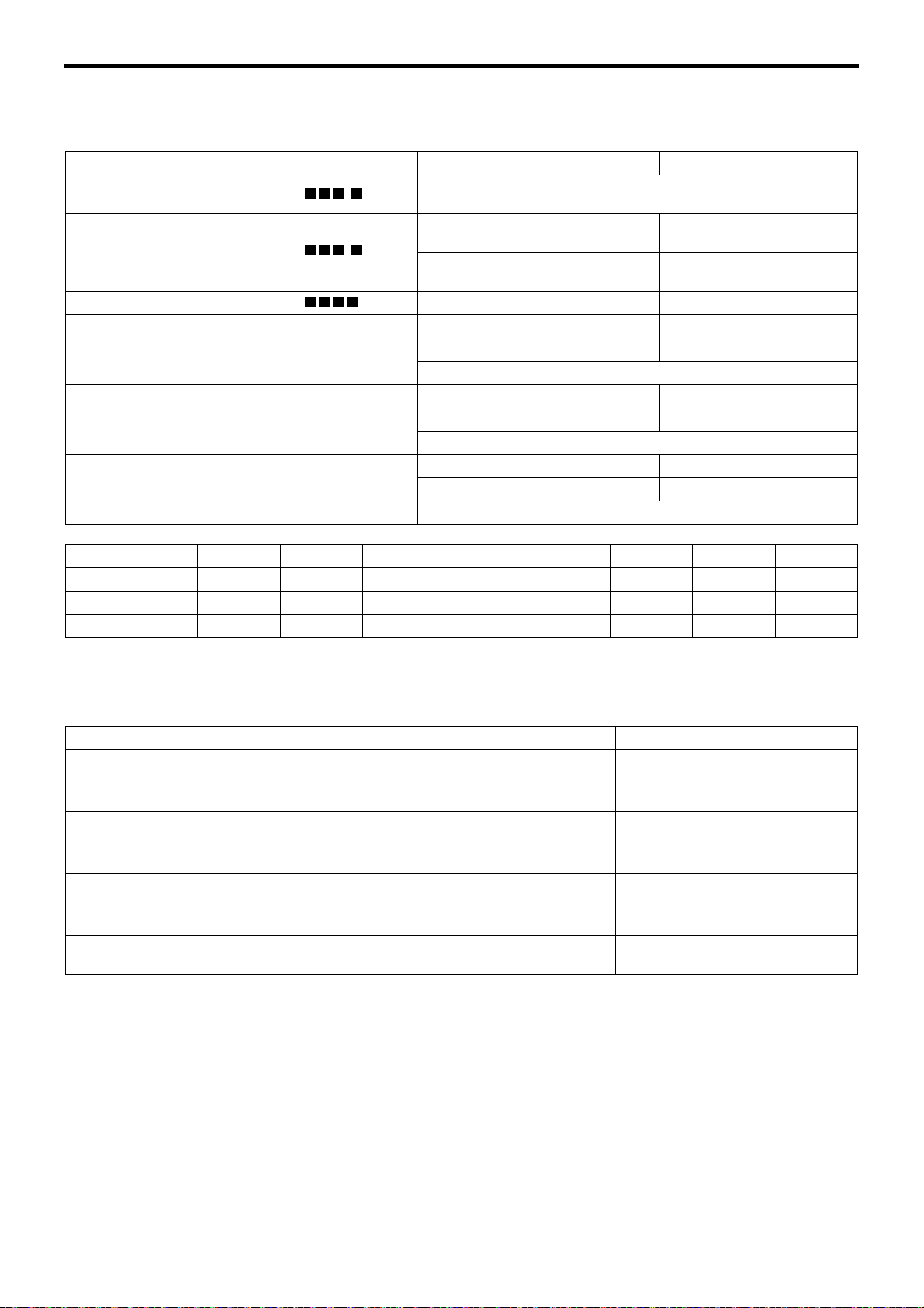
15-20
4. Multi-Use Tester Service Data
• It is possible to see service data and actuator tests simultaneously.
5. Actuator Tests by Multi-Use Tester
• It is possible to see service data and actuator tests simultaneously.
No. Item Data Inspection condition Requirement
21 VGT Position . %
VGT opening degrees displayed according to VGT M/V operations
shown below.
26 Boost Pressure
. kPa
Starter switch ON (engine is stopped)
Value matches atmospheric
pressure indication.
Accelerator pedal pressed after en-
gine has started
Value gradually increases.
2A Turbine Revolution .rpm Engine speed: 2280 to 2320 rpm 50000 to 80000 rpm
82 VGT M/V1 ON/OFF
No. 1 magnetic valve ON ON
No. 1 magnetic valve OFF OFF
[Actuator test] A9: VGT1
83 VGT M/V2 ON/OFF
No. 2 magnetic valve ON ON
No. 2 magnetic valve OFF OFF
[Actuator test] AA: VGT2
84 VGT M/V3 ON/OFF
No. 3 magnetic valve ON ON
No. 3 magnetic valve OFF OFF
[Actuator test] AB: VGT3
VGT opening (%) 0 to 12.5 to 25 to 37.5 to 50 to 62.5 to 75 to 87.5 to 100
M/V1 ON OFF ON OFF ON OFF ON OFF
M/V2 ON ON OFF OFF ON ON OFF OFF
M/V3 ON ON ON ON OFF OFF OFF OFF
No. Item Description Check method
A9 VGTM/V1 No. 1 magnetic valve activated
Magnetic valve operating sound
[Service data]
82: VGT M/V1
AA VGTM/V2 No. 2 magnetic valve activated
Magnetic valve operating sound
[Service data]
83: VGT M/V2
AB VGTM/V3 No. 3 magnetic valve activated
Magnetic valve operating sound
[Service data]
84: VGT M/V3
BA VGT Test
Used for turbo boost pressure measurement/ad-
justment
See On-Vehicle Inspection and Ad-
justment.
TURBOCHARGER CONTROL SYSTEM
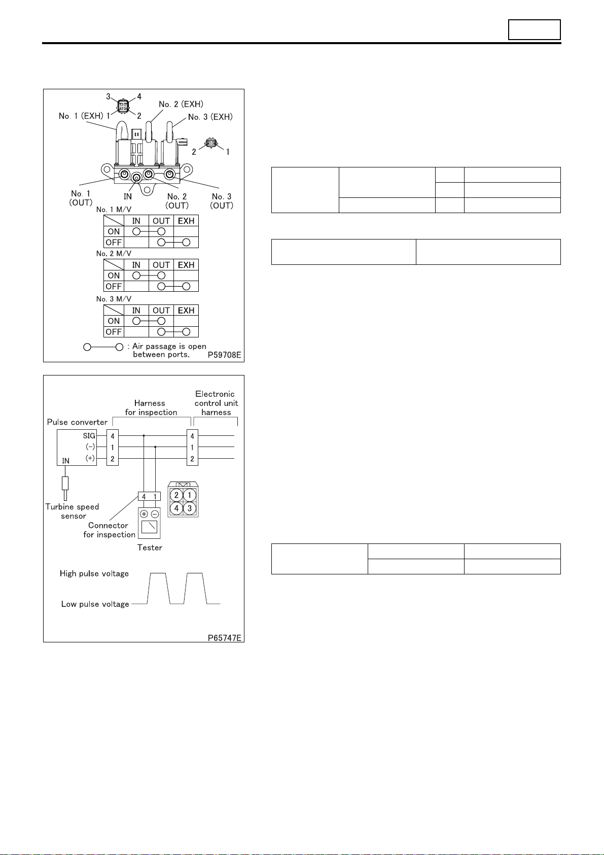
15
15-21
6. Inspection of Electrical Equipment
#566 Inspection of turbocharger magnetic valve
• Perform the following tests on the turbocharger magnetic valve.
Replace the valve if found faulty.
(1) Valve activation test
• Gradually increasing from 0 V, apply voltage to the turbocharger
magnetic valve between the following terminals.
• Measure voltage when turbocharger magnetic valve is activated.
(Listen to the operating sound for ON/OFF of the magnet valve.)
(2) Continuity and air tight test
• Test air pressure: 981 kPa {10 kgf/cm
2
}
#835 Inspection of turbine speed sensor and pulse converter
unit
• Test the turbine speed sensor and pulse converter unit as con-
nected to the turbocharger.
• Disconnect the turbine speed sensor and pulse converter unit
from the electronic control unit harness at connectors. Then,
prepare and fit the test harness in place.
• The sensor does not respond to manual rotation of the turbo-
charger compressor wheel. To make the sensor responsive,
start the engine to be idling.
• Measure the maximum level (high-pulse voltage) and minimum
level (low-pulse voltage) of voltage appearing between test con-
nector terminals 4 and 1.
• If the measurement deviates the standard value, replace the tur-
bine speed sensor and pulse converter unit.
Terminals
4-pin connector
1-3 No. 1 magnetic valve
2-4 No. 2 magnetic valve
2-pin connector 1-2 No. 3 magnetic valve
Reference value
(minimum activation voltage)
18 V or less
Standard value
Low-pulse voltage 0 V
High-pulse voltage 5 V
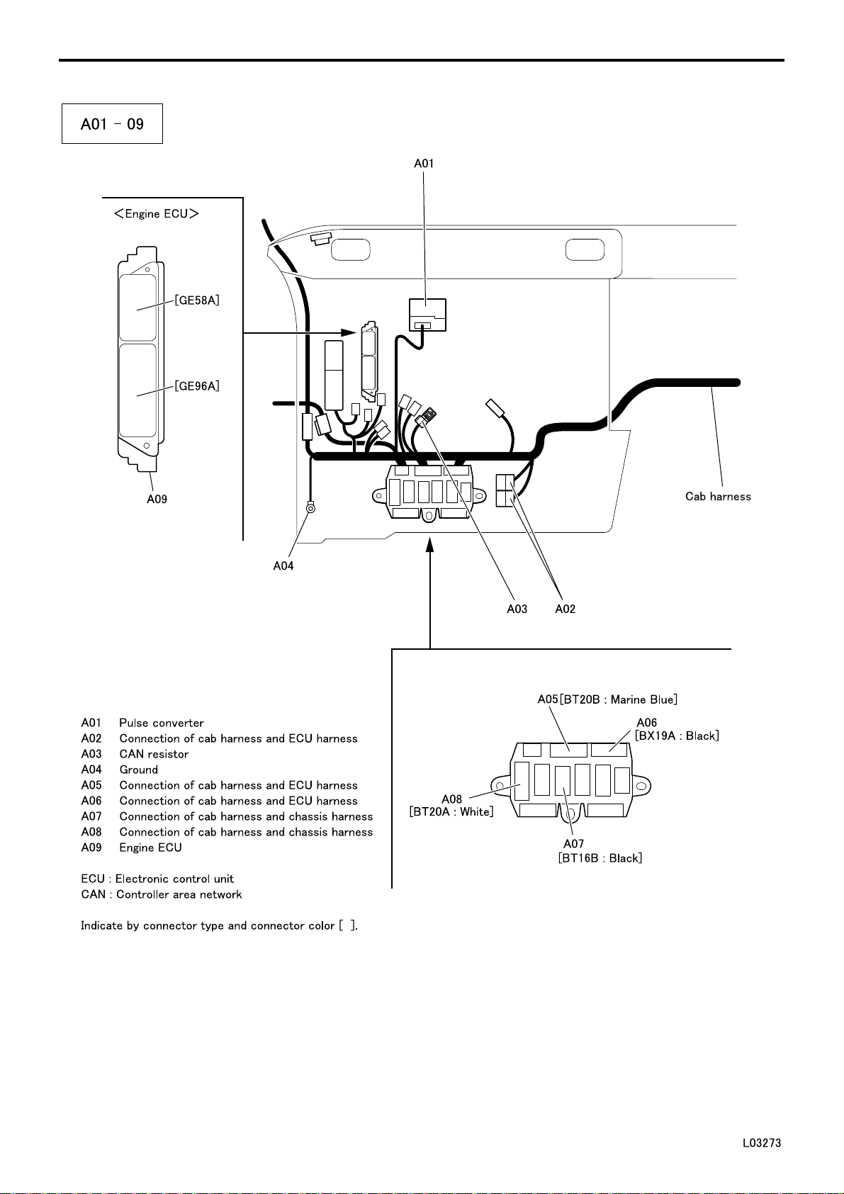
15-22
7. Installed Locations of Parts
TURBOCHARGER CONTROL SYSTEM
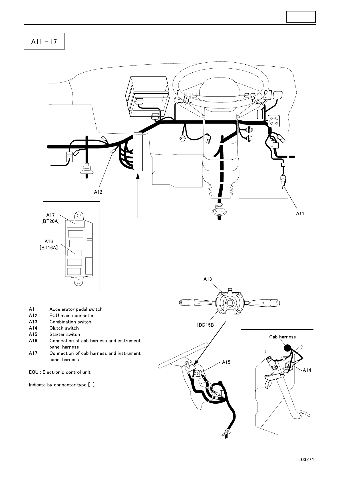
15
15-23
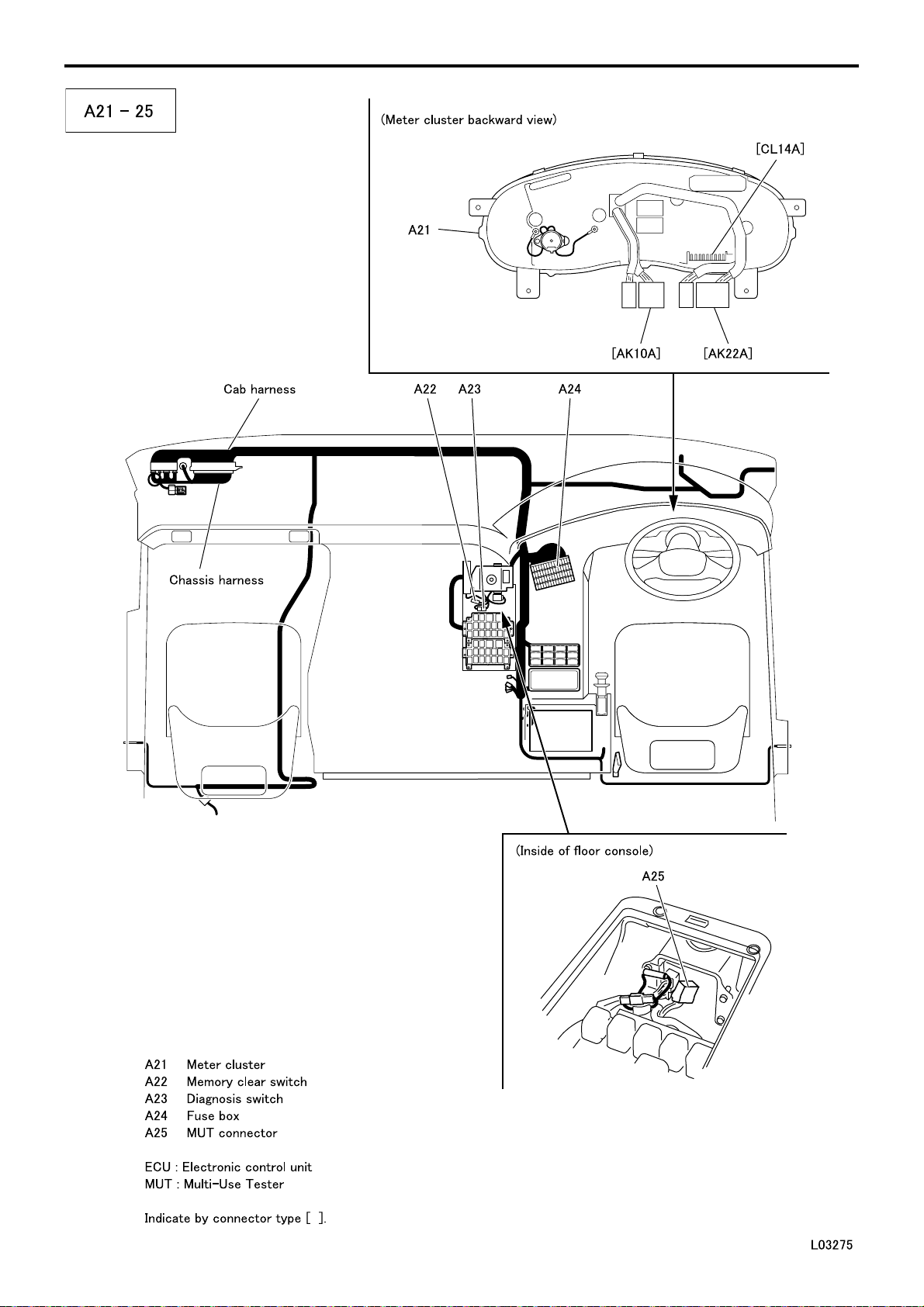
15-24
TURBOCHARGER CONTROL SYSTEM

15
15-25
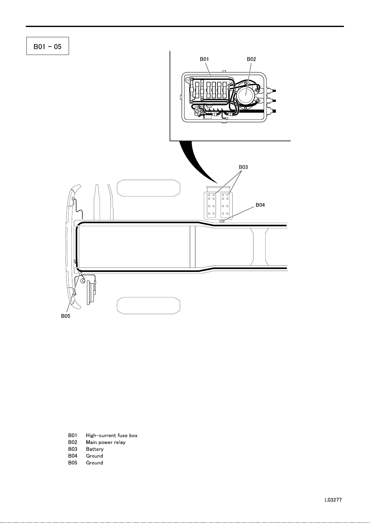
15-26
TURBOCHARGER CONTROL SYSTEM
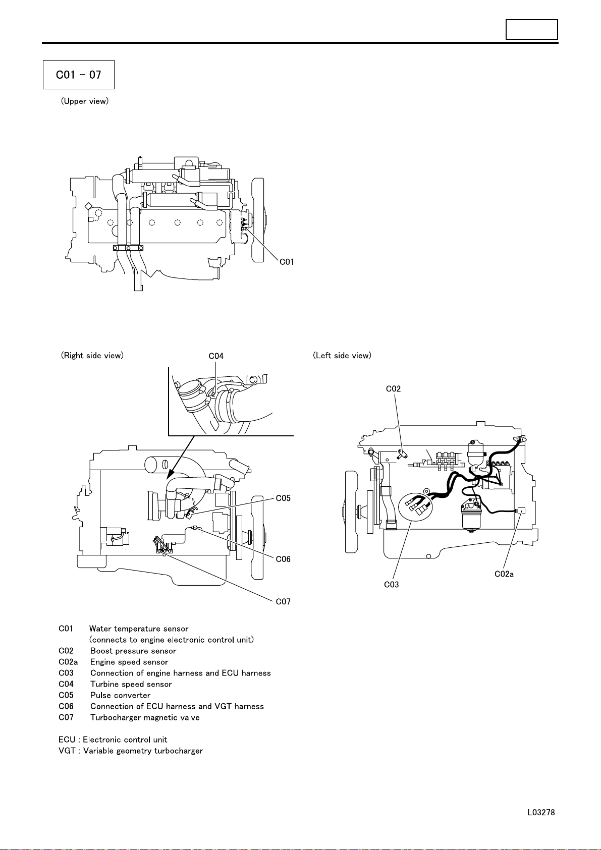
15
15-27
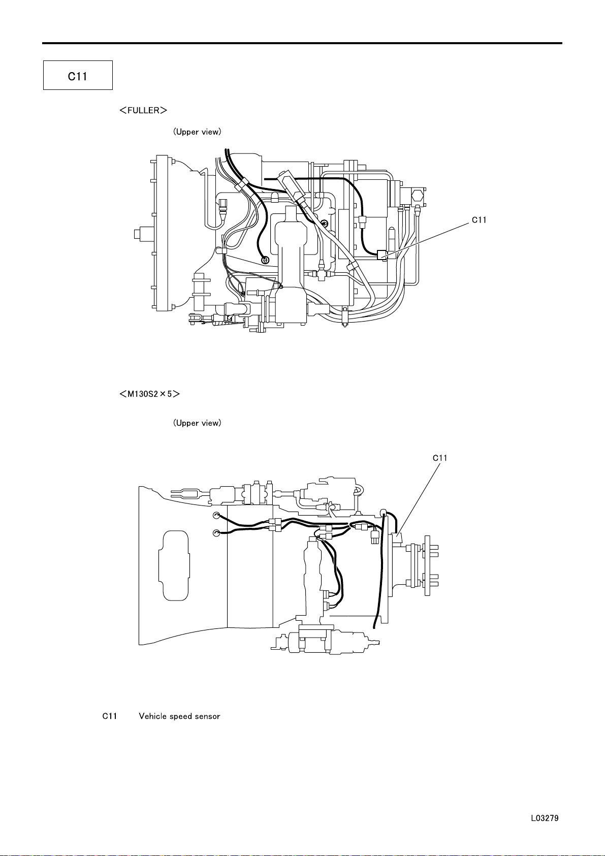
15-28
TURBOCHARGER CONTROL SYSTEM

M E M O
15-29
15
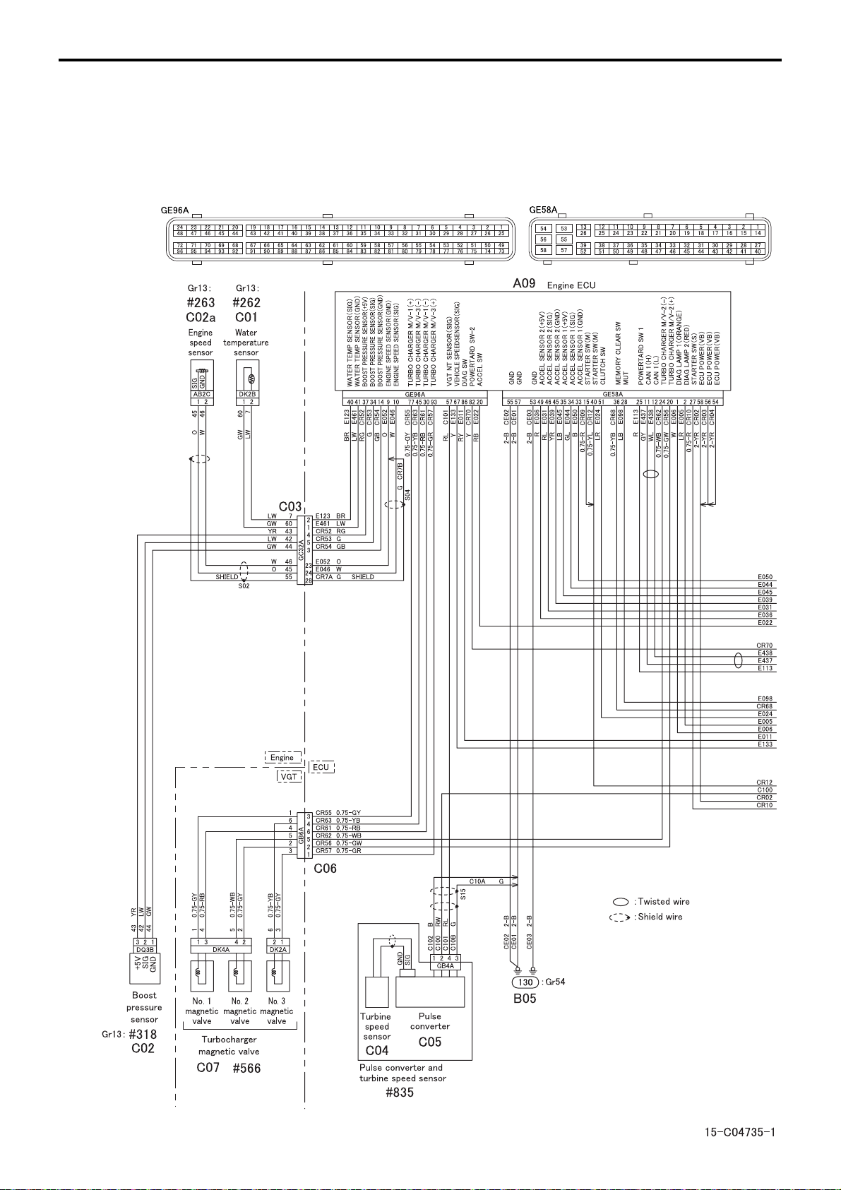
15-30
8. Electric Circuit Diagram
TURBOCHARGER CONTROL SYSTEM
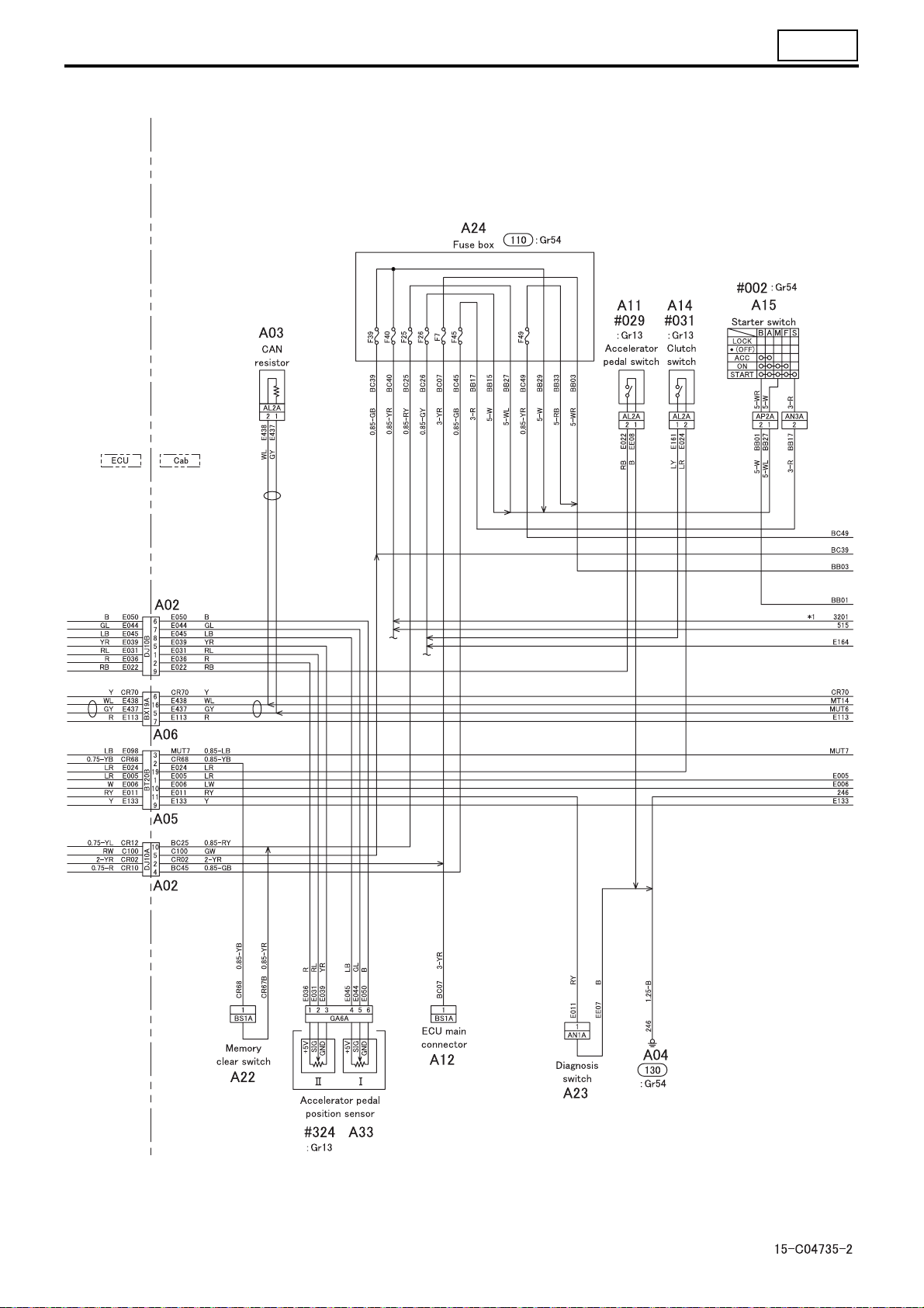
15
15-31
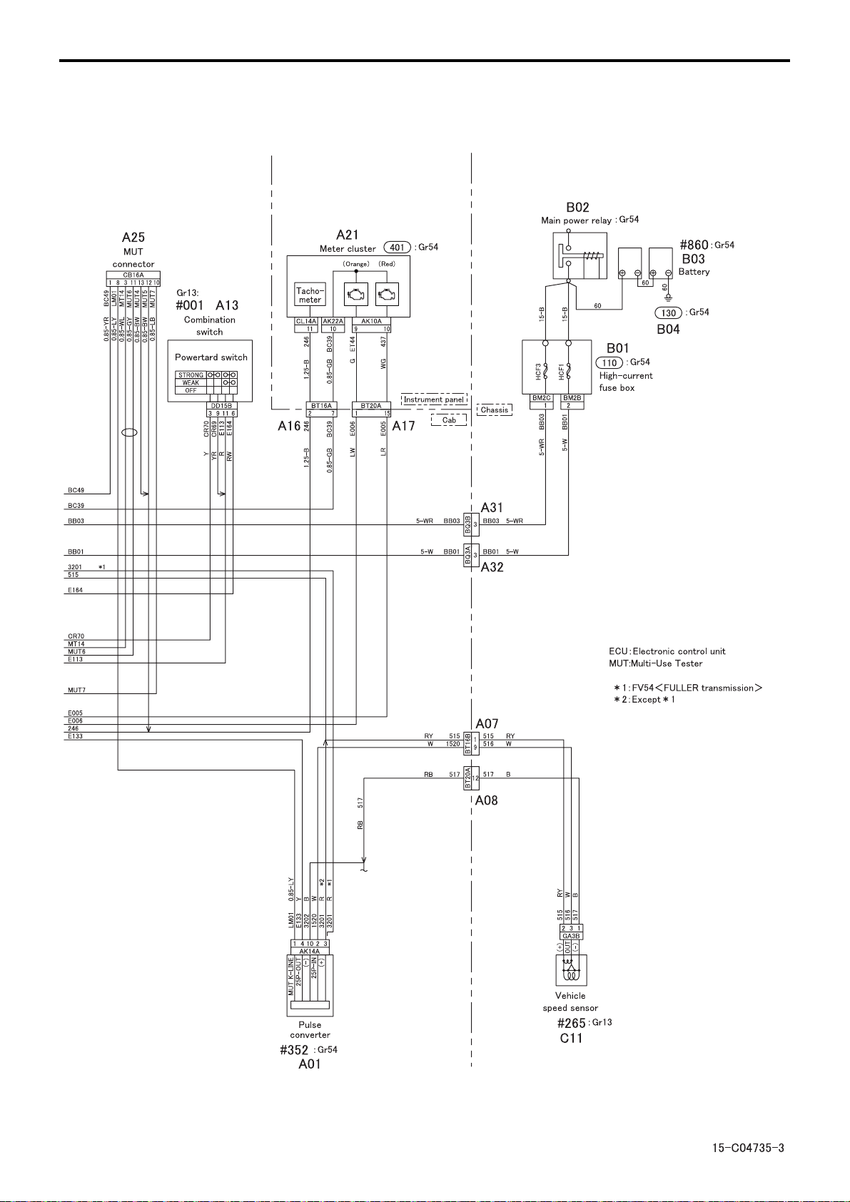
15-32
TURBOCHARGER CONTROL SYSTEM

M E M O
15-33
15
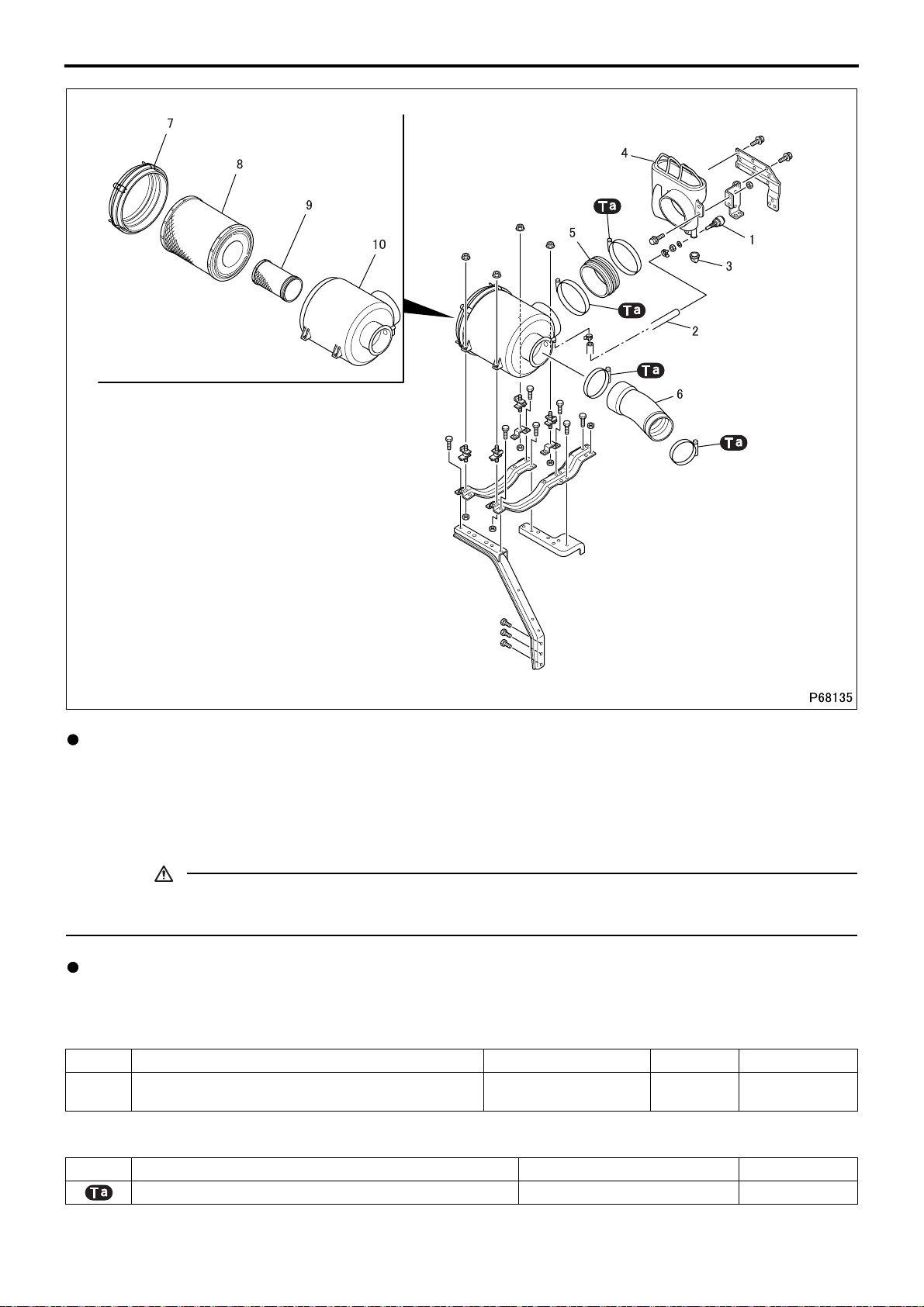
15-34
Removal sequence
CAUTION
• Do not remove the safty element except for replacement.
• Never clean the safty element.
Installation sequence
Follow the removal sequence in reverse.
Service standards
Tightening torque (Unit: N·m {kgf·m})
Location Maintenance item Standard value Limit Remedy
1 Dust indicator activating negative pressure
9.12 ± 0.69 kPa
{930 ± 70 mmH
2
O}
–Replace
Mark Parts to be tightened Tightening torque Remarks
Clamp 3.0 to 3.5 {0.3 to 0.35} –
1 Dust indicator
2 Air tube
3 Vacuator valve
4 Lower air duct
5 Duct joint hose
6 Air intake hose
7 Cover
8 Outer element
9 Safety element
10 Body
AIR CLEANER
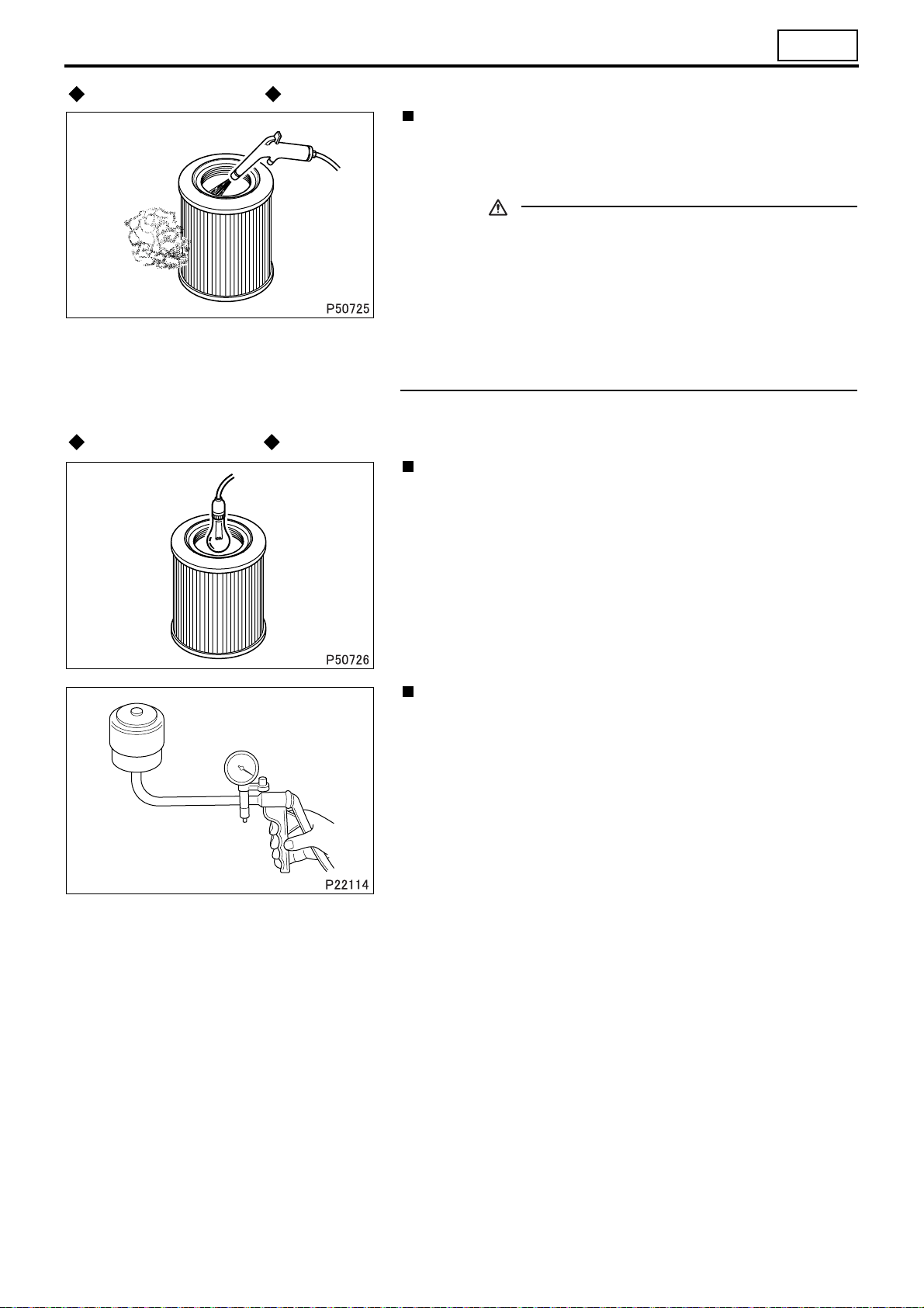
15
15-35
Cleaning procedure
Cleaning: Element
• Blow a jet of compressed air at a pressure not higher than 685
kPa {7 kgf/cm
2
} against the inside surfaces of the element.
CAUTION
• For the frequency and timing of cleaning, refer to the rele-
vant instruction manual. More frequent cleaning than nec-
essary could damage the element or cause dust and foreign
matter to be sucked into the engine.
• Do not strike the element or hit it against another object to
remove dust.
• Do not blow compressed air against outside surfaces of the
element.
Inspection procedure
Inspection: Element
• Shine some electric light inside the element.
• Replace the element if thin spots or broken parts are evident in
the filter paper, or if the packing at the top of the element is dam-
aged.
Also replace the element if the dust on the element is damp with
oily smoke or soot, regardless of the replacement schedule.
Inspection: Operation of dust indicator under specified neg-
ative pressure
• Apply negative pressure to the dust indicator, and take the read-
ing when the red signal appears in the dust indicator window.
• Replace the dust indicator if found faulty.
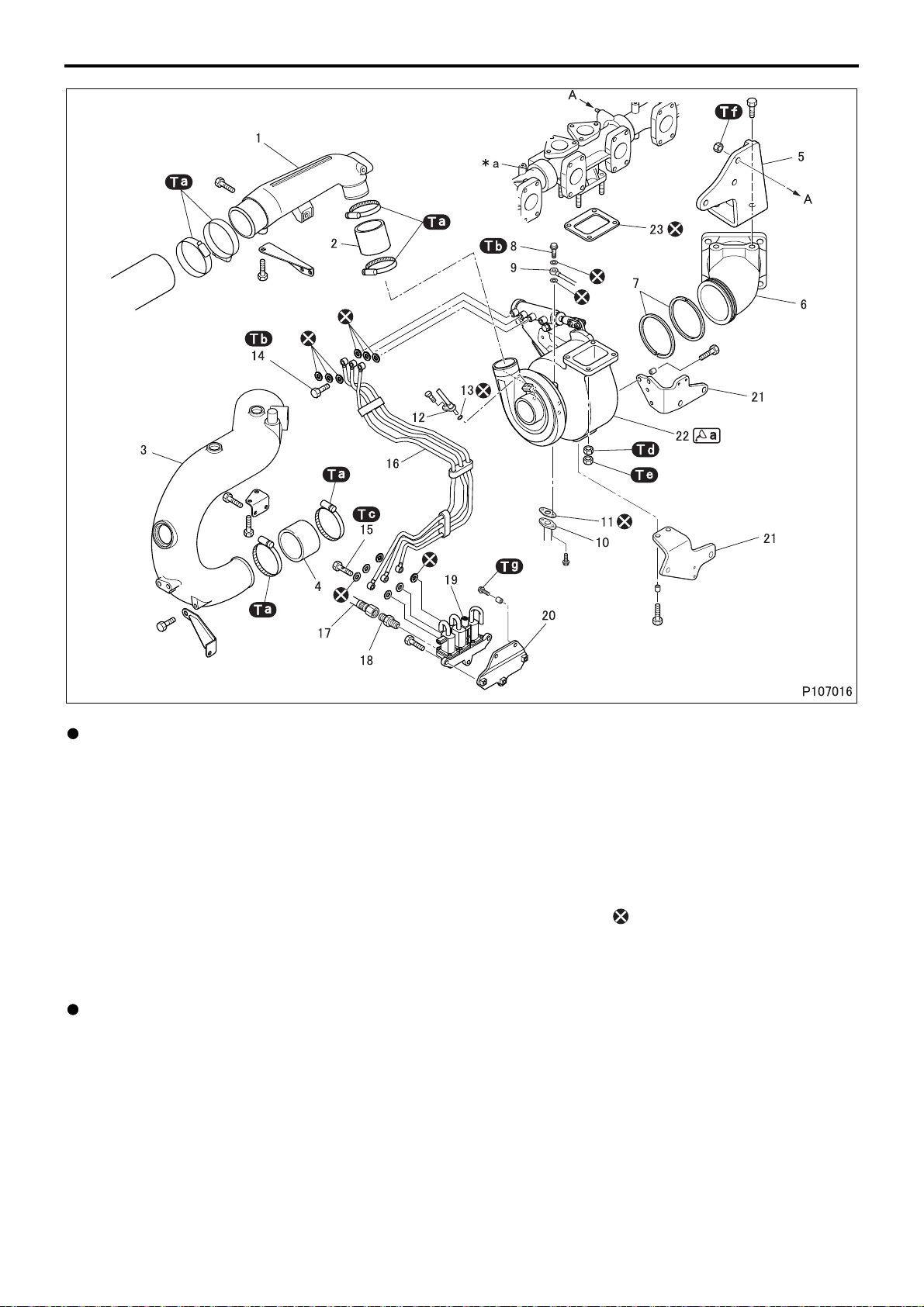
15-36
Removal sequence
Installation sequence
Follow the removal sequence in reverse.
1 Air inlet pipe
2 Air hose
3 Air pipe
4 Air hose
5 Turbocharger coupler bracket
6 Turbocharger coupler
7 Seal ring
8 Eyebolt
9 Oil feed pipe
10 Oil return pipe
11 Gasket
12 Turbine speed sensor
13 O-ring
14 Eyebolt
15 Eyebolt
16 Air pipe
17 Air hose
18 Connector
19 Turbocharger magnetic valve
20 Turbocharger magnetic valve
bracket
21 Bracket
22 Turbocharger (See later sec-
tion.)
23 Gasket
*
a: Exhaust manifold
: Non-reusable parts
M
ITSUBISHI 6M70 TURBOCHARGER ATTACHING PARTS
Mitsubishi 6M70 Engine Parts contact:
email: [email protected]
P
hone: 269 673 1638
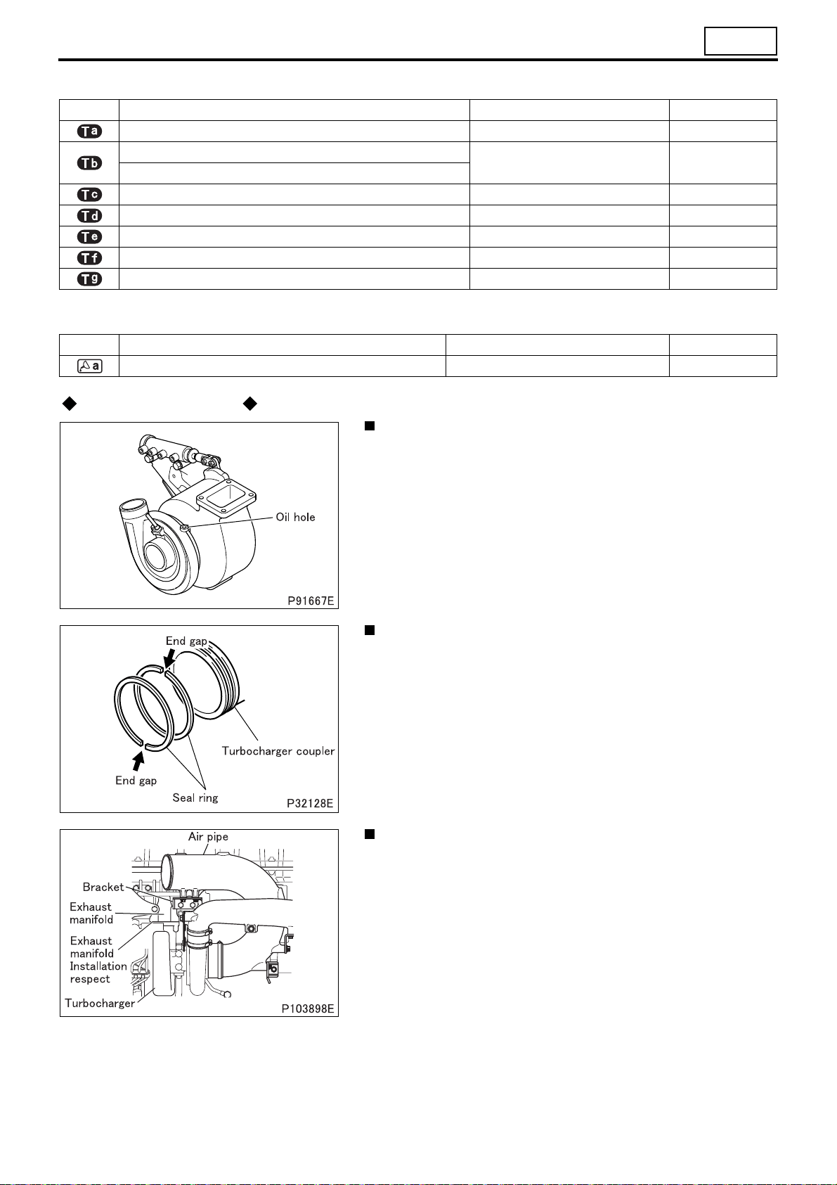
15
15-37
M
itsubishi 6M70 Tightening torque (Unit: N·m {kgf·m})
Lubricant and/or sealant
Installation procedure
Installation: Mitsubishi 6M70 Turbocharger
• Before installing the turbocharger assembly, pour engine oil into
the oil hole of the bearing housing to ensure smooth operation of
the internal parts.
Installation: Mitsubishi 6M70 Seal ring
• Fit the seal rings onto the turbocharger coupler, with their end
gaps positioned 180 degrees apart from each other.
Installation: Bracket
• Temporarily tighten the bracket on the air pipe and exhaust man-
ifold.
• Tighten the bolts after temporary tightening while ensuring that
there is no clearance at the joints between the bracket and air
pipe, and bracket and exhaust manifold.
• After installing the bracket, ensure that there is no gas leakage
from the joint of turbocharger with exhaust manifold.
Mark Parts to be tightened Tightening torque Remarks
Clamp 7.0 to 8.0 {0.7 to 0.8} –
Eyebolt (oil pipe mounting)
21 {2.1} –
Eyebolt (air pipe mounting)
Eyebolt (air pipe mounting) 25 {2.5} –
Nut (turbocharger mounting) 36 {3.7} –
Nut (turbocharger mounting) 45 {4.6} –
Nut (turbocharger coupler bracket mounting) 90 {9.0} –
Bolt (turbocharger magnetic valve bracket mounting) 75 {7.6} –
Mark Points of application Specified lubricant and/or sealant Quantity
Turbocharger (to be filled with engine oil) Engine oil As required
Mitsubishi 6M70 Engine Parts contact:
email: [email protected]
Phone: 269 673 1638
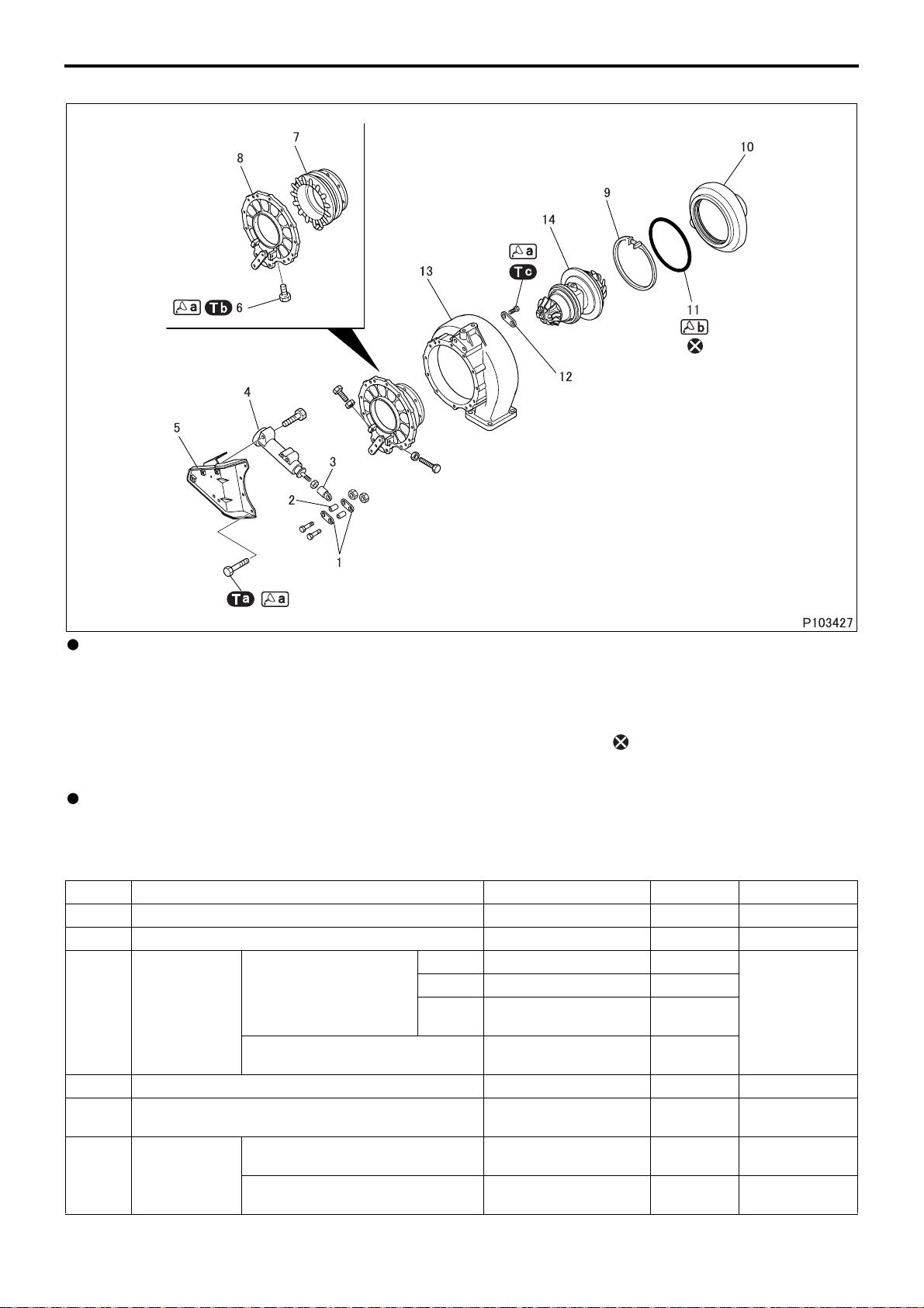
15-38
Mitsubishi 6M70 Turbocharger
Disassembly sequence
Assembly sequence
Follow the disassembly sequence in reverse.
Service standards (Unit: mm)
Location Maintenance item Standard value Limit Remedy
2 Spacer outside diameter – φ11.5 Replace
3 Joint inside diameter – φ12.5 Replace
4 Air cylinder
Stroke
(operating air pressure:
390 to 785 kPa {4 to 8 kgf/
cm
2
} when compressed air
introduced)
Port A 12 –
Replace
Port B 6 –
Port C 3 –
Airtight test (390 to 785 kPa {4 to 8
kgf/cm
2
})
No air leakage of 25 cm
2
{25 mL} for 1 minute
–
7 Play between nozzle lever plate and link 0.05 to 0.40 1.0 Replace
10, 14
Clearance between compressor cover and compressor
wheel
0.08 to 0.28 – Check parts
14
Cartridge as-
sembly
Play in axial direction of shaft and tur-
bine wheel
0.075 to 0.155 – Check parts
Shaft and turbine wheel-to-turbine
back plate clearance
0.48 to 0.92 – Check parts
1 Connecting lever
2 Spacer
3 Joint
4 Air cylinder
5 Bracket
6 Clamp bolt
7 Nozzle
8 Flange
9 Snap ring
10 Compressor cover
11 O-ring
12 Clamp plate
13 Turbine housing
14 Cartridge assembly
(See later section.)
: Non-reusable parts
TURBOCHARGER
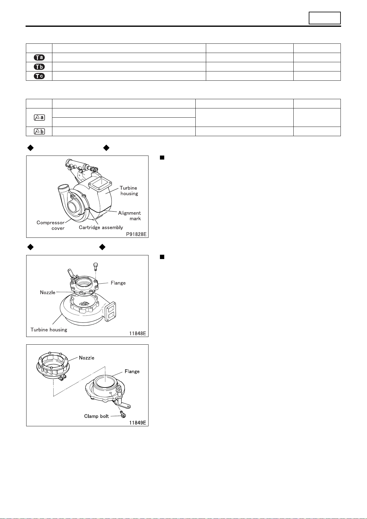
15
15-39
Tightening torque (Unit: N·m {kgf·m})
Lubricant and/or sealant
Work before removal
Alignment mark
• Put alignment marks on the coupling, turbine housing, compres-
sor cover and cartridge assembly.
Removal procedure
Removal: Nozzle
• Remove the flange and nozzle in one unit from the turbine hous-
ing.
• Remove the clamp bolt, then remove the nozzle from the flange.
Mark Parts to be tightened Tightening torque Remarks
Bolt (bracket mounting) 34 to 38 {3.5 to 3.9} Wet
Clamp bolt 6.4 to 7.4 {0.65 to 0.75} Wet
Bolt (clamp plate mounting) 25.5 to 27.4 {2.6 to 2.8} Wet
Mark Points of application Specified lubricant and/or sealant Quantity
Threads of clamp bolt
Seizure preventive compound
(FEL-PRO CA-5)
As required
Threads of mounting bolt
O-ring Engine oil As required
Mitsubishi 6M70 Engine Parts contact:
email: EngineParts@HeavyEquipm
entRestorationParts.com
Phone: 269 673 1638
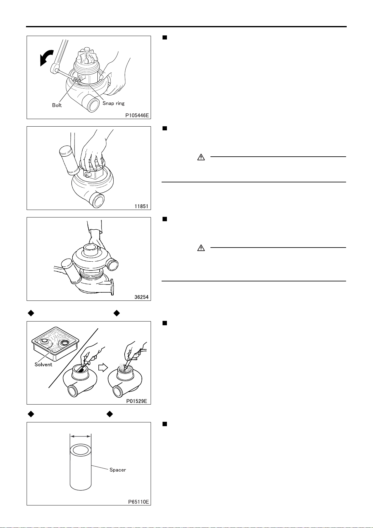
15-40
Removal: Snap ring
• Tighten the bolt to contract the snap ring and remove the ring.
Removal: Compressor cover
• Lightly tap around the entire periphery of the compressor cover
with a rubber-faced hammer, taking care not to cause damage.
CAUTION
• The blades on the cartridge assembly are easily bent. Make
sure that they do not strike the compressor cover.
Removal: Turbine housing
• Lightly tap around the entire periphery of the turbine housing
with a rubber-faced hammer, taking care not to cause damage.
CAUTION
• The blades of the turbine wheel on the cartridge assembly
are easily bent. Make sure that they do not strike the turbine
housing.
Work after disassembly
Cleaning
• Before cleaning, visually check the disassembled parts for
scorches, abrasion and other marks that may be difficult to see
after cleaning. Replace any part that appears de
fective.
• Immer
se the disassembled parts in a non-flammable solvent (a
5 to 10 aqueous solution of Oil Clean from New Hope Co., Ltd.).
Take out the parts and blow them dry with compressed air. Re-
move any hard deposits with a stiff brush or plastic scraper.
• Again, immerse the parts in the solvent.
• Blow them dry using compressed air.
Inspection procedure
Inspection: Spacer outside diameter
• If the measurement is less than the specified limit, replace the
spacer.
TURBOCHARGER
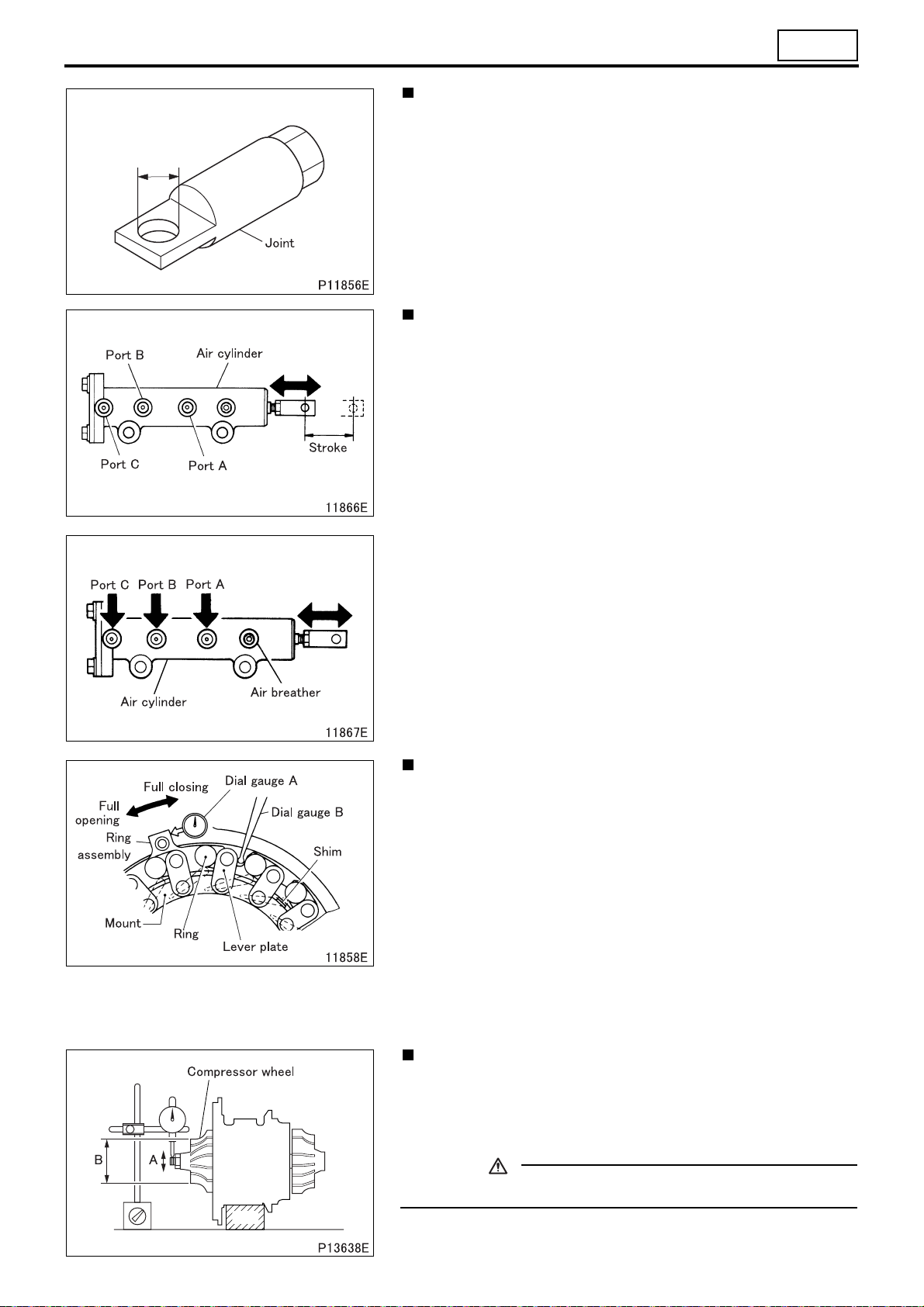
15
15-41
Inspection: Joint inside diameter
• If the measurement exceeds the specified limit, replace the joint.
Inspection: Air cylinder
(1) Stroke
• Apply specified air pressure to the ports (A to C) in the air cylin-
der, one at a time, and measure the corresponding strokes of
the air cylinder.
• If the measurement deviates from the standard value, replace
the air cylinder.
(2) Airtight test
• Apply specified air pressure to the ports (A to C) in the air cylin-
der, one at a time, and measure air leakage per minute using an
air breather.
• If the measurement exceeds the standard value, replace the air
cylinder.
Inspection: Nozzle
• Move the ring assembly of the nozzle all the way by hand from
“full opening” to “full closing” and measure its travel with a dial
gauge A.
• Position the ring assembly roughly in the middle of measured
length of its travel.
• To center and hold the ring assembly and mount in place, use
appropriate shims equally spaced at 3 places between them.
Type of shim
• Width × length: 5 mm × 10 mm
• Thickness: 0.1 mm to 0.4 mm
• Measure the play between each lever plate and ring with the dial
gauge B. If any of the measurements exceeds the specified limit,
replace the nozzle.
Inspection: Clearance between compressor cover and com-
pressor wheel
• Measure the maximum runout A of the compressor wheel when
the wheel is moved in vertical direction.
• Measure the outside diameter B of the compressor wheel.
CAUTION
• Do not rotate the compressor wheel for axial play measurement.
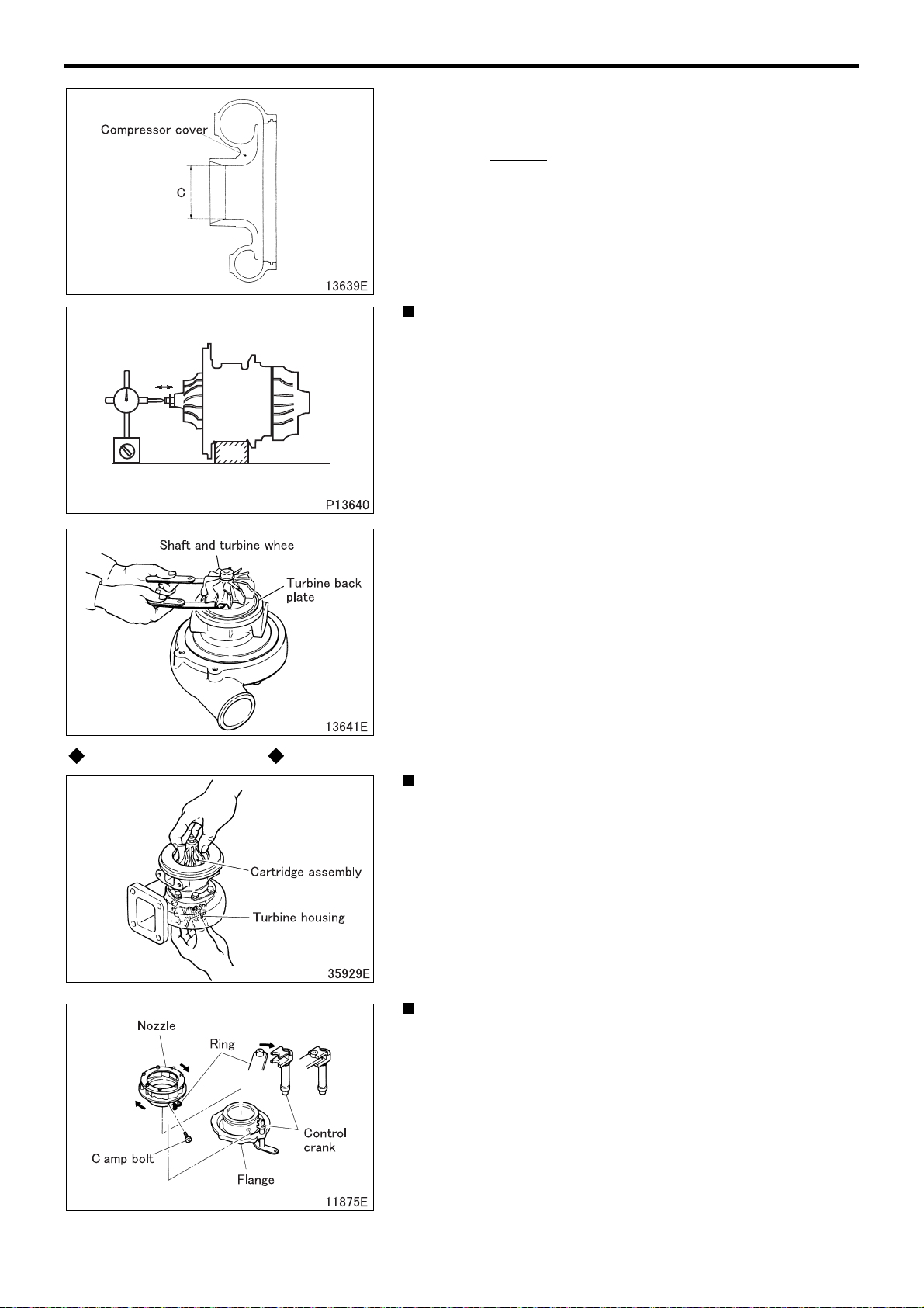
15-42
• Measure the inside diameter C of the compressor cover.
• Calculate the clearance between compressor wheel and com-
pressor cover as follows.
• If the clearance deviates from the specified standard value
range, disassemble and correct.
Inspection: Cartridge assembly
(1
) Play in axial direc
tion of shaft and turbine wheel
• If the measurement exceeds the specified limit, disassemble
and check the parts.
(2
) Shaf
t and turbine wheel-to-turbine back plate clearance
• Measure the clearance between the turbine back plate and shaft
and turbine wheel unit.
• Be sure to measure the clearance at the periphery of the blades
using two feeler gauges.
• If the measurement deviates from the standard value, disassem-
ble the cartridge assembly, inspect and check the parts.
Installation procedure
Installation: Turbine housing
• Install the cartridge assembly into the turbine, then perform the
following test.
(1) Rotating condition of cartridge assembly
• Turn the wheels of the cartridge assembly. They should turn
smoothly
.
• If no
t, disassemble the cartridge assembly, inspect and check
the parts.
Installation: Nozzle
• Fit the nozzle in the flange.
• In fitting, turn the nozzle and flange so that the control crank and
ring properly engage each other
Clearance=
C-B-A
2
TURBOCHARGER
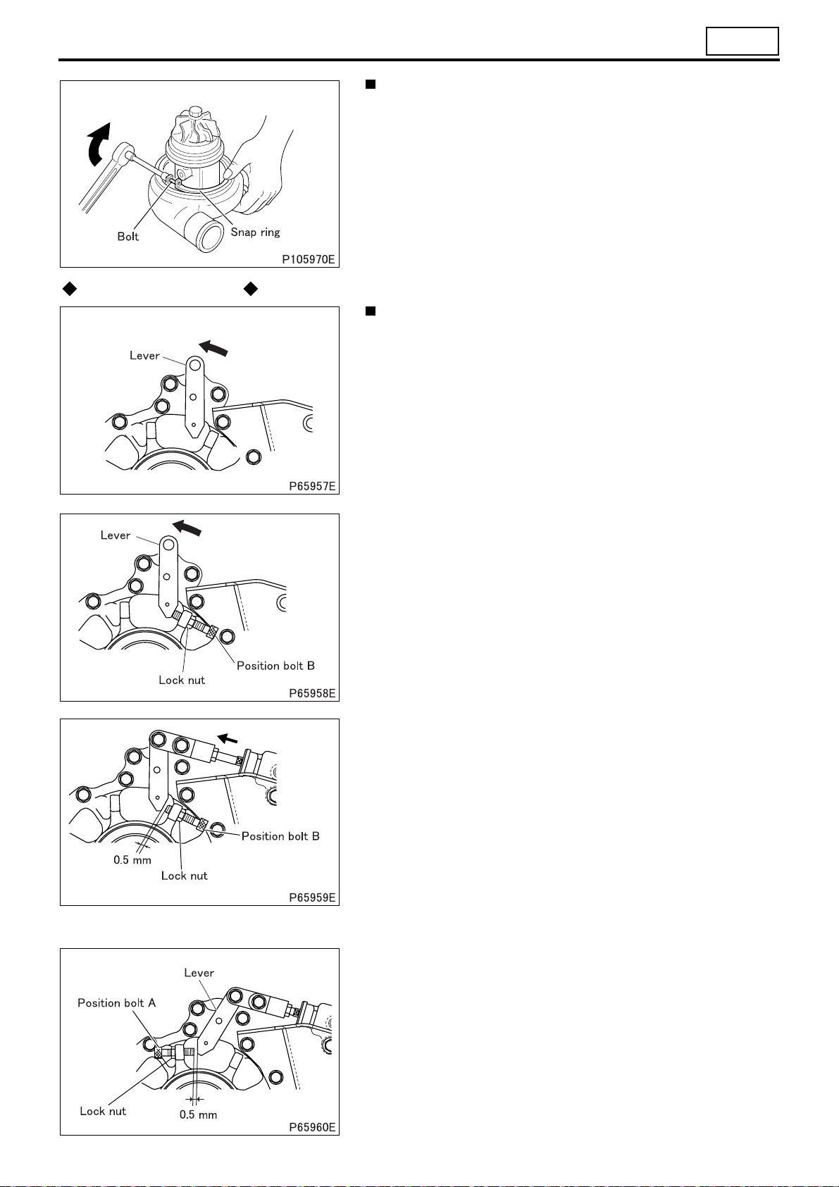
15
15-43
Installation: Snap ring
• Turn the snap ring in its mounting groove to confirm proper seat-
ing of the ring. After confirmation, loosen the bolt and fit the ring
securely.
Work after installation
Adjustment: Positioning of air cylinder
(1) Full closing position
• Remove the position bolt B, then move the lever all the way in
the illustrated direction.
(2) Temporary tightening of position bolt
• Reinstall the position bolt B, and drive it in until it contacts the le-
ver.
• Mark the position bolt B at that position, give it 5 and half turns,
then tighten the lock nut to secure the position bolt B.
(3) Readjustment for full closing position
• Introduce specified pressure in the air cylinder from the port A,
B, C and bring the air cylinder into the state of full stroke, then
connect the lever to the joint.
• Make sure that the lever is in slight contact with the position bolt
B. If there is an open space between the lever and position bolt
B or the lever is pushing the position bolt B, loosen the lock nut
and make necessary adjustment by turning the shaft. Then,
tighten the lock nut.
• Back up the position bolt B a half turn for a clearance of approxi-
mately 0.5 mm between the bolt and lever, then tighten the lock
nut to secure the position bolt B in that position.
(4) Full opening position
• Release compressed air to bring the air cylinder into the sate of
zero stroke. Adjust the position bolt A for a clearance of 0.5 mm
between the bolt and lever, then tighten the lock nut to secure
the bolt in that position.
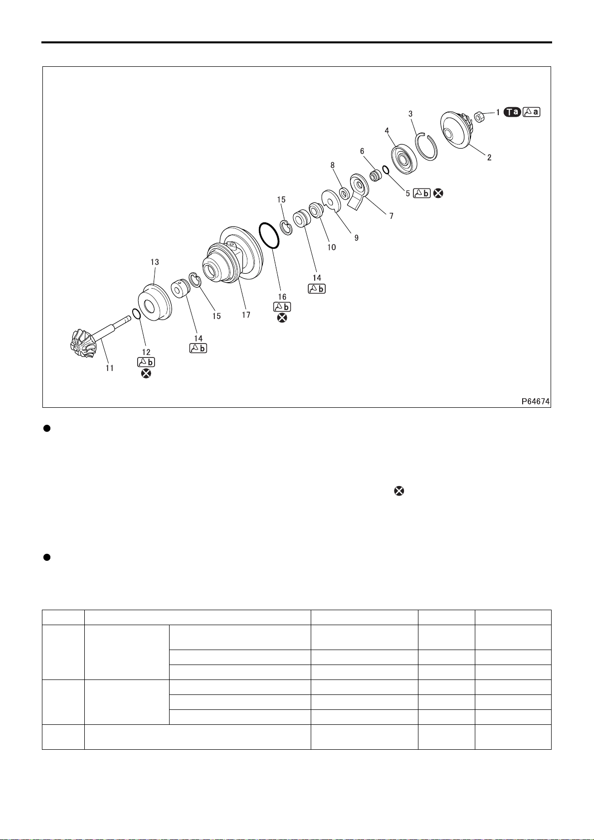
15-44
Cartridge Assembly
Disassembly sequence
Assembly sequence
Follow the disassembly sequence in reverse.
Service standards (Unit: mm)
Location Maintenance item Standard value Limit Remedy
11
Shaft and turbine
wheel
Turbine housing-to-shaft and tur-
bine wheel clearance
0.39 to 1.0 – Replace
Bearing journal outside diameter – 11.996 Replace
Shaft bend – 0.015 Replace
14 Bearing
Outside diameter – 20.382 Replace
Inside diameter – 12.042 Replace
Length – 11.94 Replace
17
Inside diameter of bearing insertion bore in bearing
housing
– 20.506 Replace
1 Lock nut
2 Compressor wheel
3 Snap ring
4 Insert
5 Piston ring
6 Thrust sleeve
7 Oil deflector
8 Thrust ring
9 Thrust bearing
10 Thrust ring
11 Shaft and turbine wheel
12 Piston ring
13 Turbine back plate
14 Bearing
15 Snap ring
16 O-ring
17 Bearing housing
: Non-reusable parts
MITSUBISHI 6M70 TURBOCHARGER PARTS
Mitsubis
hi 6M70 Engine Parts contact:
email: [email protected]
Phone: 269 673 1638
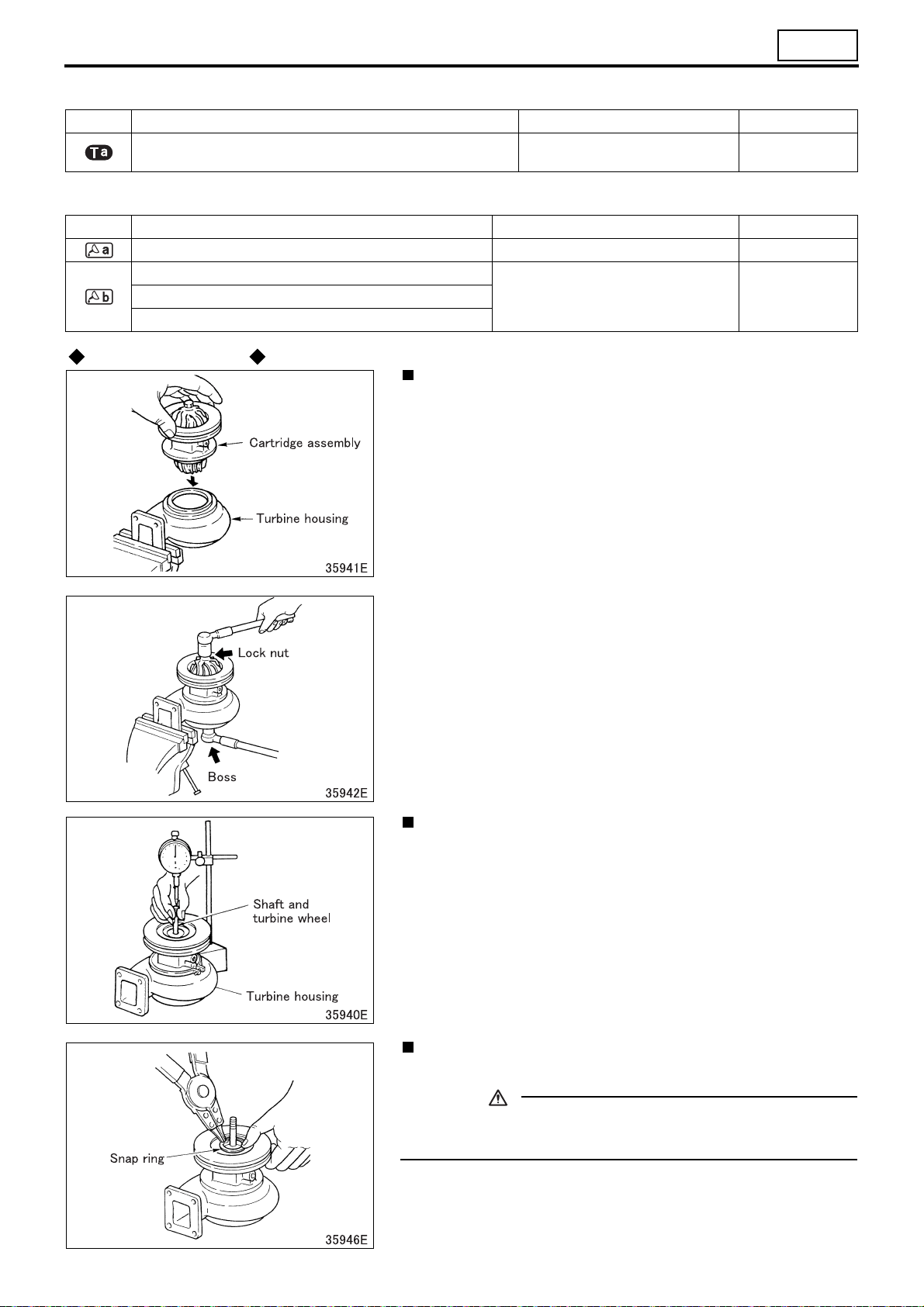
15
15-45
Tightening torque (Unit: N·m {kgf·m})
Lubricant and/or sealant
Removal procedure
Removal: Compressor wheel
• Secure the turbine housing in a vise.
• Fit the turbine wheel side of the cartridge assembly into the tur-
bine housing.
• Hold the boss on the shaft and turbine wheel unit to prevent the
cartridge assembly from turnin
g.
• Lo
osen and remove the lock nut.
Inspection: Turbine housing-to-shaft and turbine wheel
clearance
• If the measurement deviates from the standard value, replace
the defective part.
Removal: Snap ring
• Remove the snap ring.
CAUTION
• Remove the snap ring while holding it with your hand to
prevent it from springing off.
Mark Parts to be tightened Tightening torque Remarks
Lock nut 20 {2.0}
Thread-locking
compound
Mark Points of application Specified lubricant and/or sealant Quantity
Thread of lock nut Molykote BR-2 Plus As required
O-ring
Engine oil As requiredPiston ring
Bearing
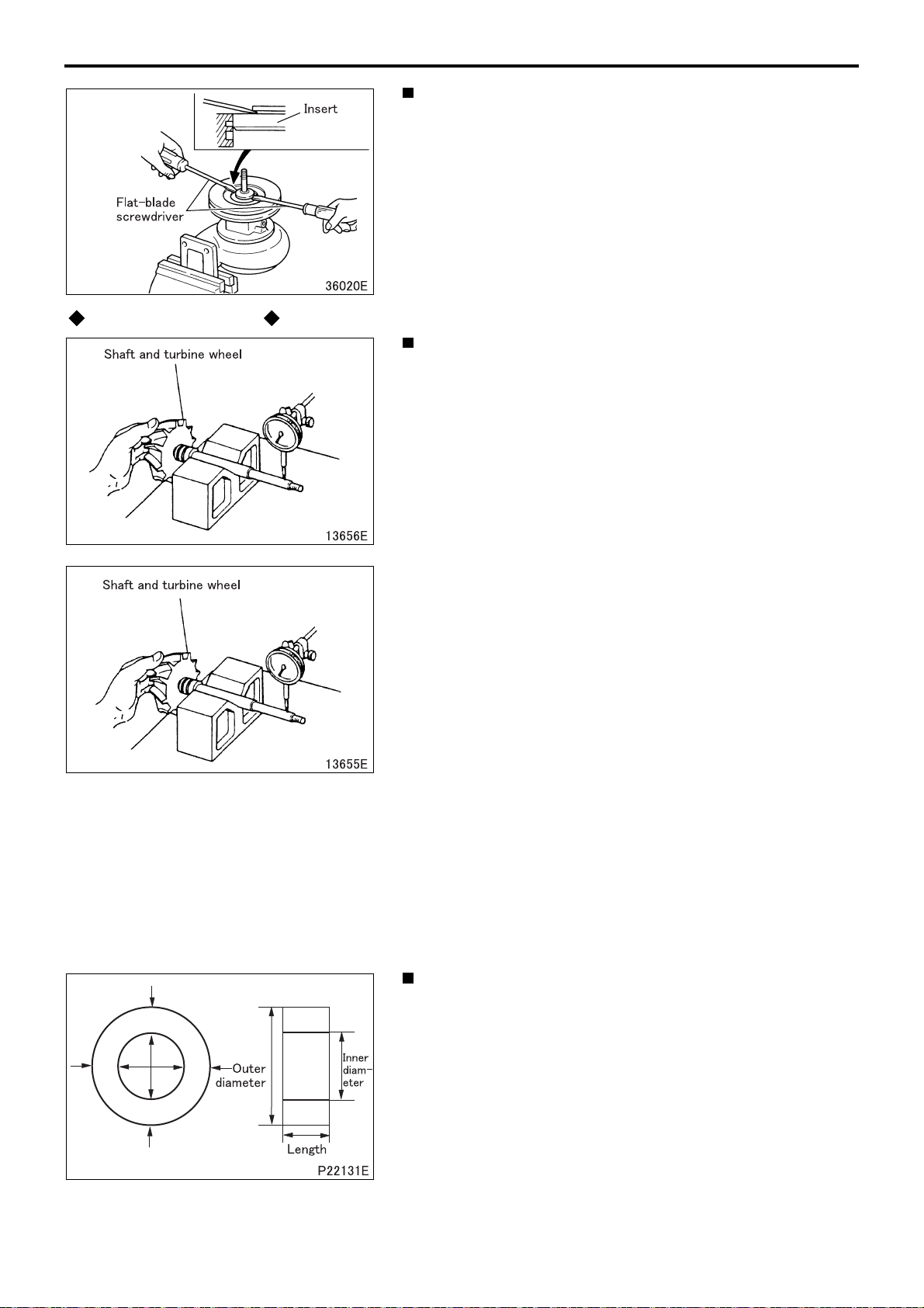
15-46
Removal: Insert
Inspection procedure
Inspection: Shaft and turbine wheel
[Inspection]
(1) Journal outside diameter
• If the measurement exceeds the specified limit or uneven wear
is excessive, replace the shaft and turbine wheel uni
t.
• Inspect th
e journal visually and recondition it if roughened.
(2) Shaft bend
• Set a dial gauge at the illustrated position on the shaft. Turning
the shaft slowly, measure the extent of bending.
• If the measurement exceeds the specified limit, replace the shaft
and turbine wheel unit.
[Reconditioning]
• Attach the shaft and turbine wheel unit to a lathe, supporting it at
both centers.
• With the shaft and turbine wheel unit turning at 300 to 600 rpm,
smooth the journal using sandpaper (#400) and engine oil.
• Measure the outside diameter of the bearing contact portion. If
the measurement exceeds the specified limit, replace the shaft
and turbine wheel unit.
Inspection: Bearing
• If the measurement exceeds the specified limit, replace the
bearing.
TURBOCHARGER
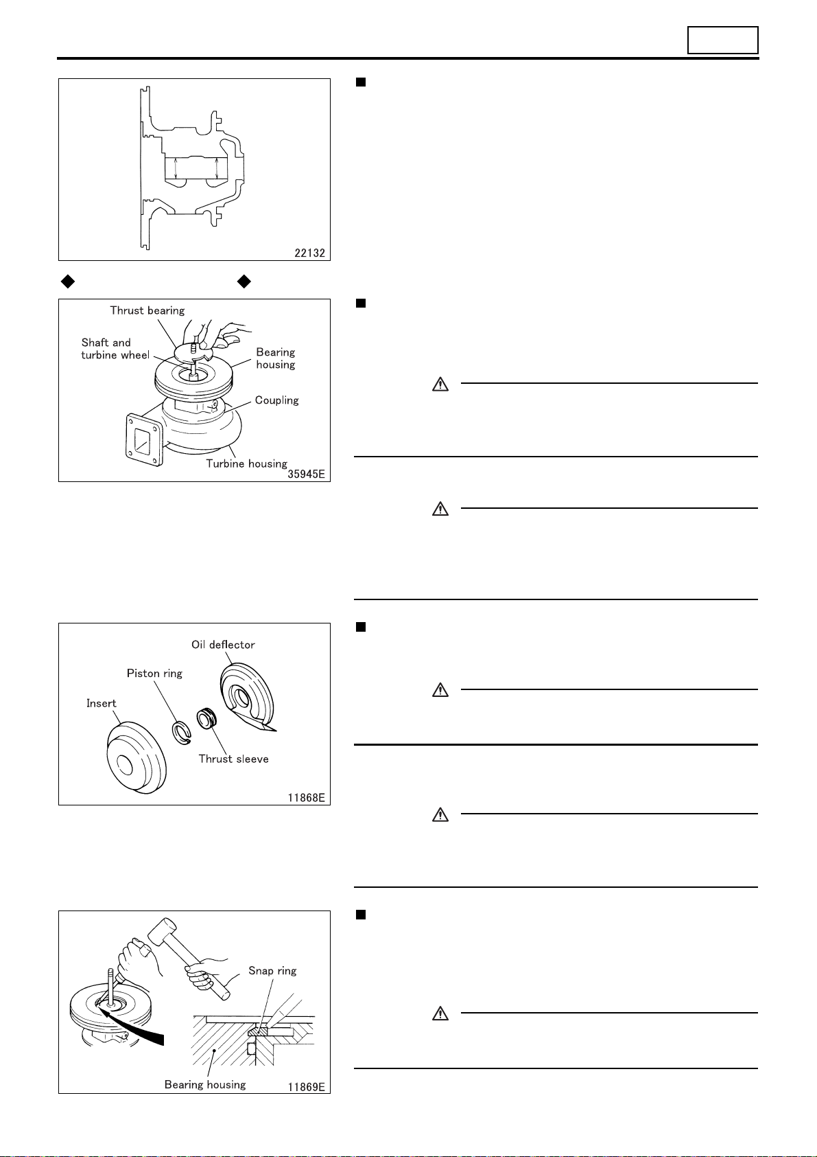
15
15-47
Inspection: Bearing housing
• If the measurement exceeds the specified limit, replace the
bearing housing.
Installation procedure
Installation: Thrust bearing
• Install the shaft and turbine wheel unit, fitted in the bearing hous-
ing, in the turbine housing. Fasten it in place temporarily with the
coupling.
CAUTION
• When installing the shaft and turbine wheel unit, make sure
that its blades are not damaged by striking the turbine
housing because they are easily bent.
• Fit the thrust bearing onto the shaft and turbine wheel unit.
CAUTION
• Before installing the thrust bearing, wipe off dirt and oily
substance completely from the stepped area of the shaft
and both sides of the thrust ring using dry tissue paper or
the like.
Installation: Insert
• Fit the piston ring onto the thrust sleeve, then fit it into the insert,
its end gap first, taking care that it is not damaged.
CAUTION
• When fitting the piston ring, use care not to open it exces-
sively or twist its end gap portion.
• Fit necessary parts in the insert first, then fit the insert into the
bearing housing.
CAUTION
• Before installing the insert, wipe off dirt and oily substance
completely from both end faces of the thrust sleeve using
dry tissue paper or the like.
Installation: Snap ring
• Place the snap ring in the bearing housing in the illustrated di-
rection using a pair of snap ring pliers.
• Then, using a screwdriver, tap the snap ring at its break ends
into place in the mating groove of the bearing housing.
CAUTION
• Fit the snap ring while holding it with your hand to prevent
it from springing off.
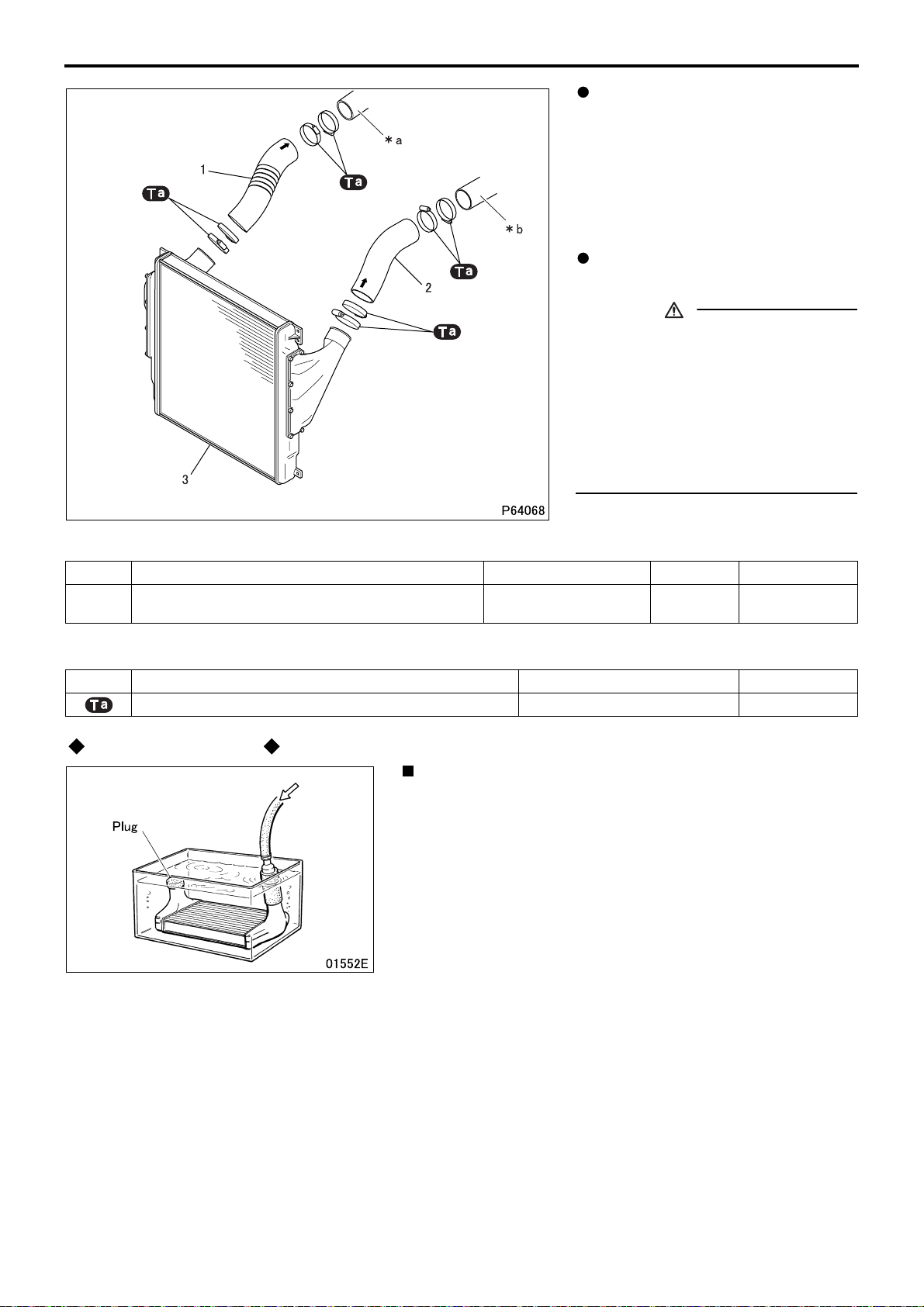
15-48
Removal sequence
1 Air inlet hose
2 Air outlet hose
3 Intercooler
*
a: Turbocharger
*
b: Intake throttle
Installation sequence
Follow the removal sequence in reverse.
CAUTION
• When removing the air inlet hose,
do not try to pry it off with strong
force using a screwdriver or other
similar tools. Doing that can dam-
age the fluorolayer on the inner sur-
face of the hose, possibly
compromising the oil resistance of
the hose.
Service standards
Tightening torque (Unit: N·m {kgf·m})
Inspection procedure
Inspection: Intercooler
• Plug one of the air ports of the intercooler and immerse it in a
tank of water. Apply the specified air pressure to the intercooler
through the other air port.
• If leakage is apparent, replace the intercooler.
Location Maintenance item Standard value Limit Remedy
3
Intercooler air leakage
(at air pressure of 147 kPa {1.5 kgf/cm
2
})
0 cm
3
{0 mL} – Replace
Mark Parts to be tightened Tightening torque Remarks
Clamp 7 to 8 {0.7 to 0.8} –
INTERCOOLER
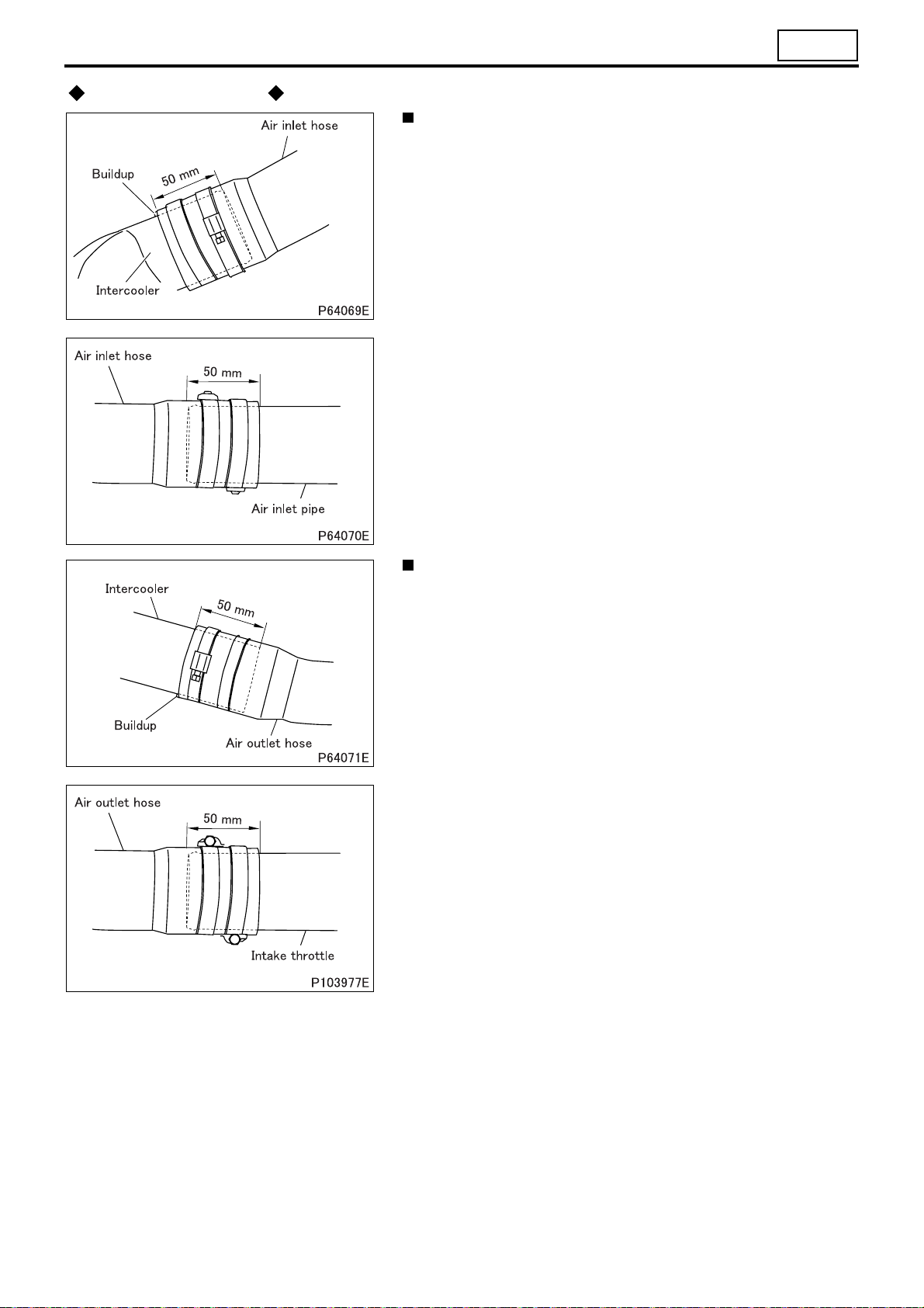
15
15-49
Installation procedure
Installation: Air inlet hose
• Fit the air inlet hose to the intercooler and air inlet pipe to the il-
lustrated dimension.
Installation: Air outlet hose
• Fit the air outlet hose to the intercooler and air inlet pipe to the il-
lustrated dimension.
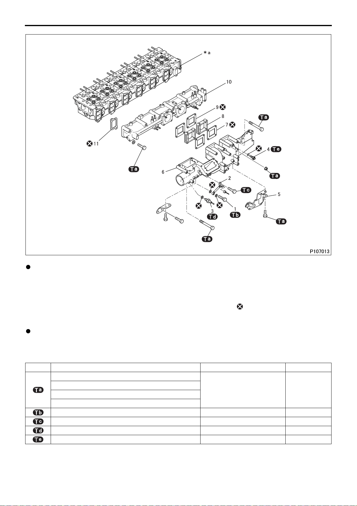
15-50
Disassembly sequence
Assembly sequence
Follow the disassembly sequence in reverse.
Tightening torque (Unit: N·m {kgf·m})
Mark Parts to be tightened Tightening torque Remarks
Bolt (intake manifold mounting)
54 {5.5} –
Bolt (air inlet pipe mounting)
Bolt (bracket mounting)
Nut (air inlet pipe mounting)
Eyebolt 21 {2.1} –
Bolt (boost pressure sensor mounting) 4 to 6 {0.4 to 0.6} –
Intake air temperature sensor 1 20 {2.0} –
Intake air temperature sensor 2 25
± 5 {2.5 ± 0.5} –
1 Eyebolt
2 Boost pressure sensor
3 Intake air temperature sensor
4 Intake air temperature sensor
(dummy)
5 Bracket
6 Air inlet pipe
7 Gasket
8 Spacer
9 Gasket
10 Intake manifold
11 Gasket
*
a: Cylinder head (See Gr11.)
: Non-reusable parts
M
ITSUBISHI 6M70 INTAKE MANIFOLD
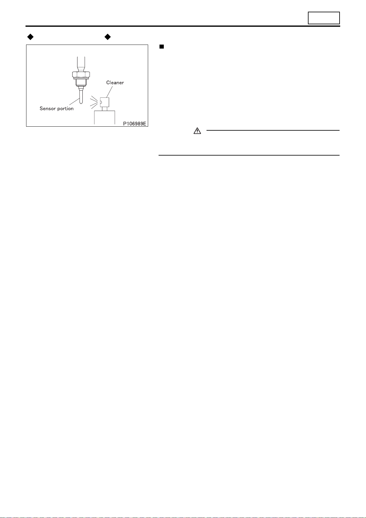
15
15-51
Inspection procedure
Inspection: Intake air temperature sensor
• Check that the sensor portion is free of soot, oily substance, etc.
• If not, clean the sensor portion as follows.
• Spray a cleaner on the sensor portion from 2 or 3 cm away.
Recommended cleaners:
Wako Chemical brake and parts cleaner from Wako Ch
emical
T
rusco Nakayama brake and parts cleaner ALP-BP
Chemsearch Lexite LO
• In 20 to 30 seconds after spraying, wipe the sensor portion clear
of the sprayed cleaner using a soft waste cloth or the like.
CAUTION
• Be sure to wait for 20 or 30 seconds before wiping. It takes
the cleaner that long to dissolve foreign matter.
• If the sensor portion is fouled excessively, the positive crankcase
ventilation (PCV) may be faulty. Inspect the PCV valve and filter
to locate the cause and remove it.
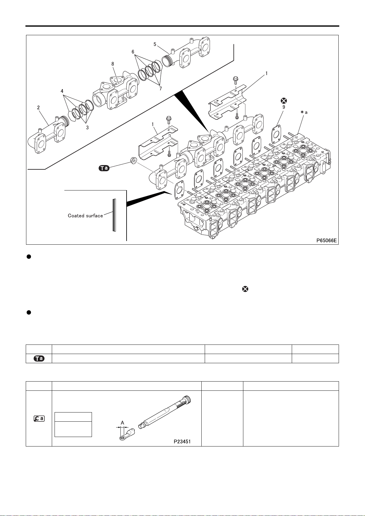
15-52
Disassembly sequence
Assembly sequence
Follow the disassembly sequence in reverse.
M
itsubishi 6M70 Tightening torque (Unit: N·m {kgf·m})
Special tools (Unit: mm)
Mark Parts to be tightened Tightening torque Remarks
Nut (exhaust manifold mounting) 42 {4.2} –
Mark Tool name and shape Part No. Application
MH063080 Installation of exhaust manifold
1 Insulator
2 Front exhaust manifold
3 Seal ring
4 Exhaust Manifold Expansion rings
5 Rear exhaust manifold
6 Seal ring
7 Expansion ring
8 Center exhaust manifold
9 Exhaust Manifold Gaskets
*
a: Cylinder head (See Gr11.)
: Non-reusable parts
Torque wrench
A
Double
flat
surfaced 14
MITSUBISHI 6M70 EXHAUST MANIFOLD
Mits
ubishi 6M70 Engine Parts contact:
email: [email protected]
Phone: 269 673 1638
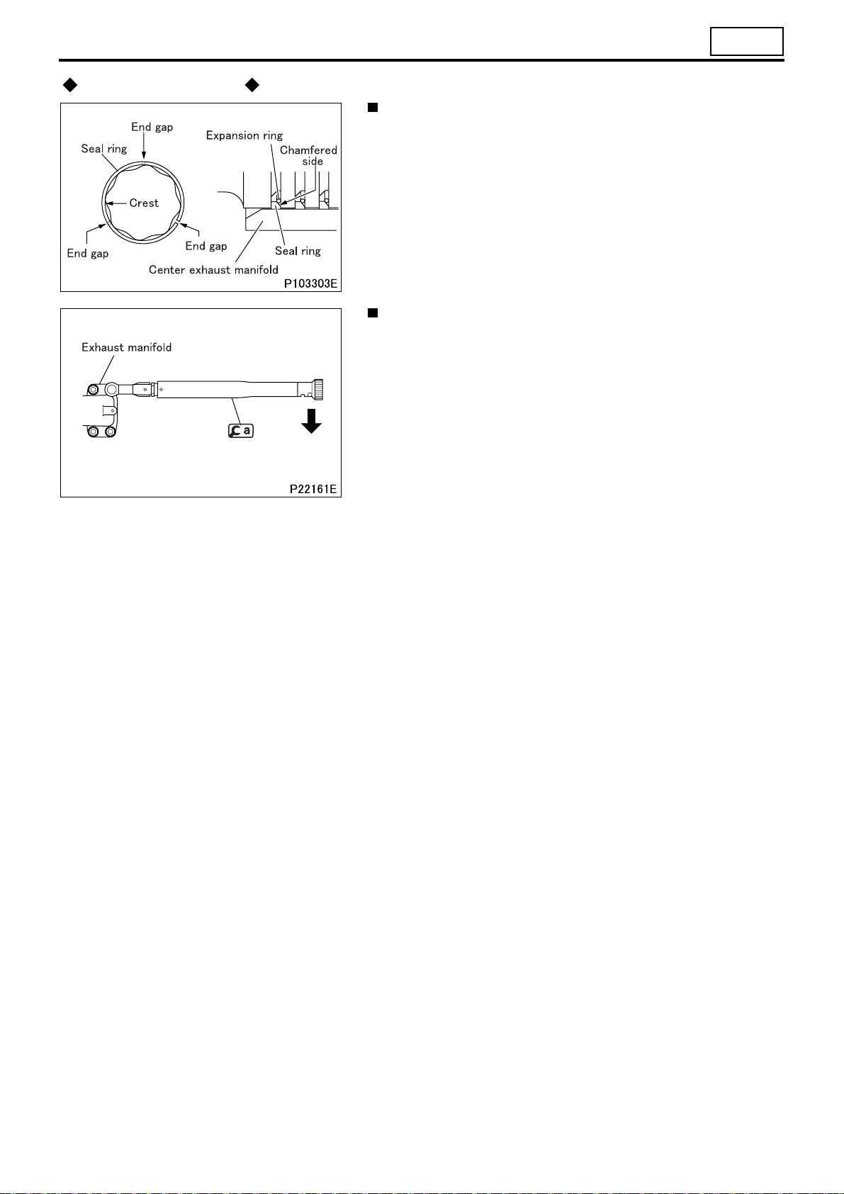
15
15-53
Installation procedure
Installation: Mitsubishi 6M70 Expansion rings and seal rings
• Fit the seal rings with their end gaps positioned 120 degrees
apart from each other.
• Fit the expansion rings so that their crests do not meet the end
gaps of the seal ring
s.
• Fit the seal rings with their chamfered sides facing the center ex-
haust manifold.
Installation: Mitsubishi 6M70 Exhaust manifold
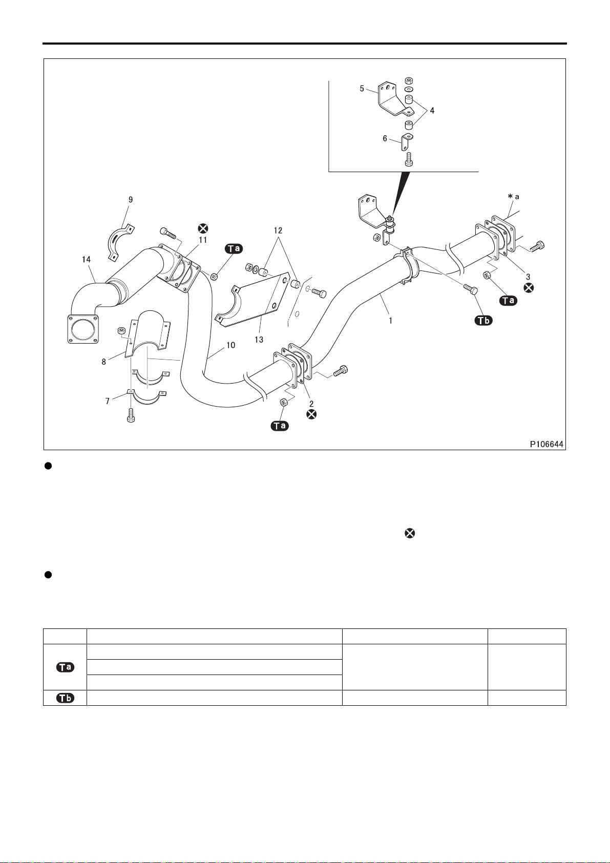
15-54
Disassembly sequence
Installation sequence
Follow the removal sequence in reverse.
Tightening torque (Unit: N·m {kgf·m})
Mark Parts to be tightened Tightening torque Remarks
Nut (upper front pipe mounting)
85 to 110 {8.7 to 11.0} –Nut (center front pipe mounting)
Nut (lower front pipe mounting)
Bolt (clamp mounting) 20
± 3 {2.1 ± 0.3} –
1 Lower front pipe
2 Gasket
3 Gasket
4 Rubber cushion
5 Exhaust pipe hanger
6 Stay
7 Clamp
8 Exhaust pipe cover
9 Clamp
10 Center front pipe
11 Gasket
12 Rubber cushion
13 Clamp
14 Upper front pipe
*
a: Diesel Particulate Filter
: Non-reusable parts
EXHAUST PIPE <FS>
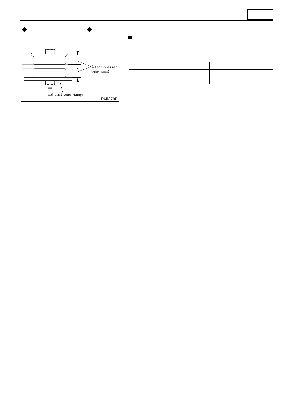
15
15-55
Installation procedure
Installation: Rubber cushions
• Tighten the rubber cushions until they are compressed to the
thickness A.
Location of rubber cushion Compressed thickness
Upper front pipe 10 mm
Lower front pipe 23 mm
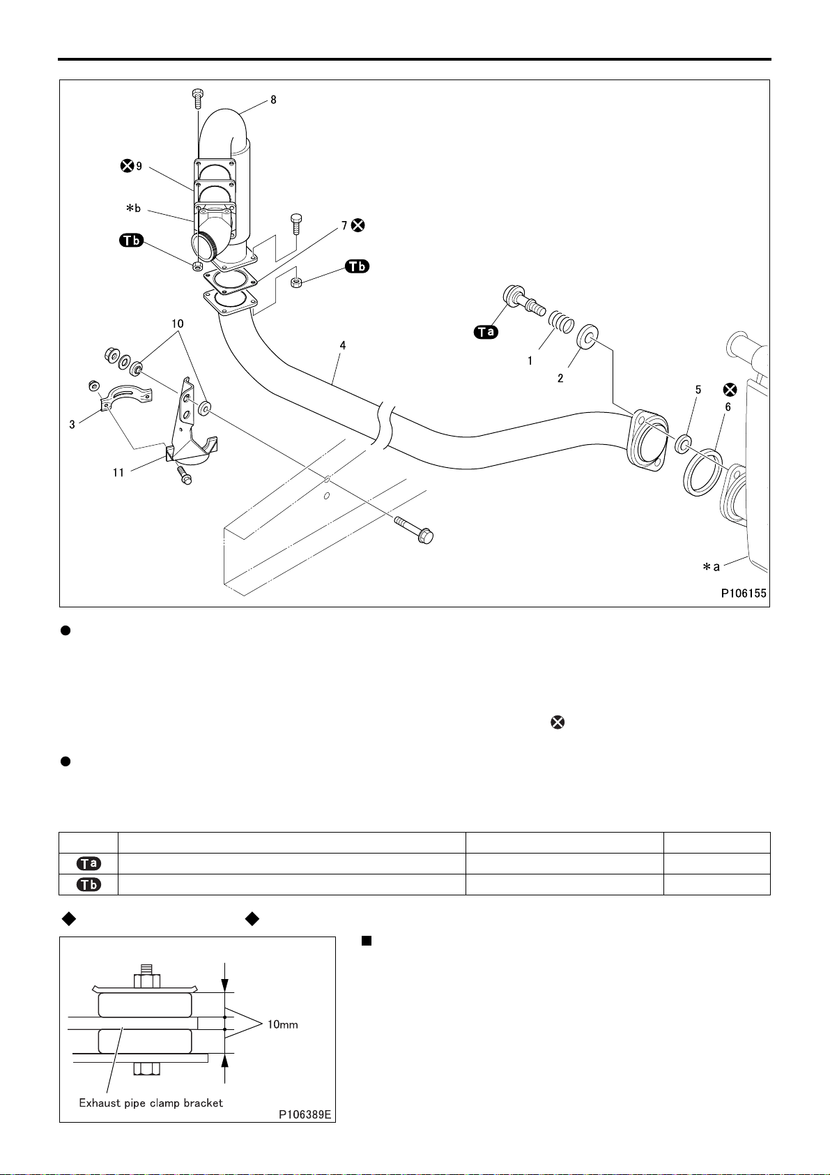
15-56
Disassembly sequence
Installation sequence
Follow the removal sequence in reverse.
Tightening torque (Unit: N·m {kgf·m})
Installation procedure
Installation: Rubber cushions
• Tighten the rubber cushions until they are compressed to the il-
lustrated dimension.
Mark Parts to be tightened Tightening torque Remarks
Bolt (lower front pipe mounting) 44
± 10 {4.5 ± 1.0} –
Nut (upper front pipe mounting) 85 to 110 {8.7 to 11.0} –
1 Spring
2 Washer
3 Clamp
4 Lower front pipe
5 Washer
6 Seal ring
7 Gasket
8 Upper front pipe
9 Gasket
10 Rubber cushion
11 Exhaust pipe clamp bracket
*
a: Diesel Particulate Filter
*
b: Turbocharger coupler
: Non-reusable parts
EXHAUST PIPE <EXCEPT FS>

M E M O
15-57
15
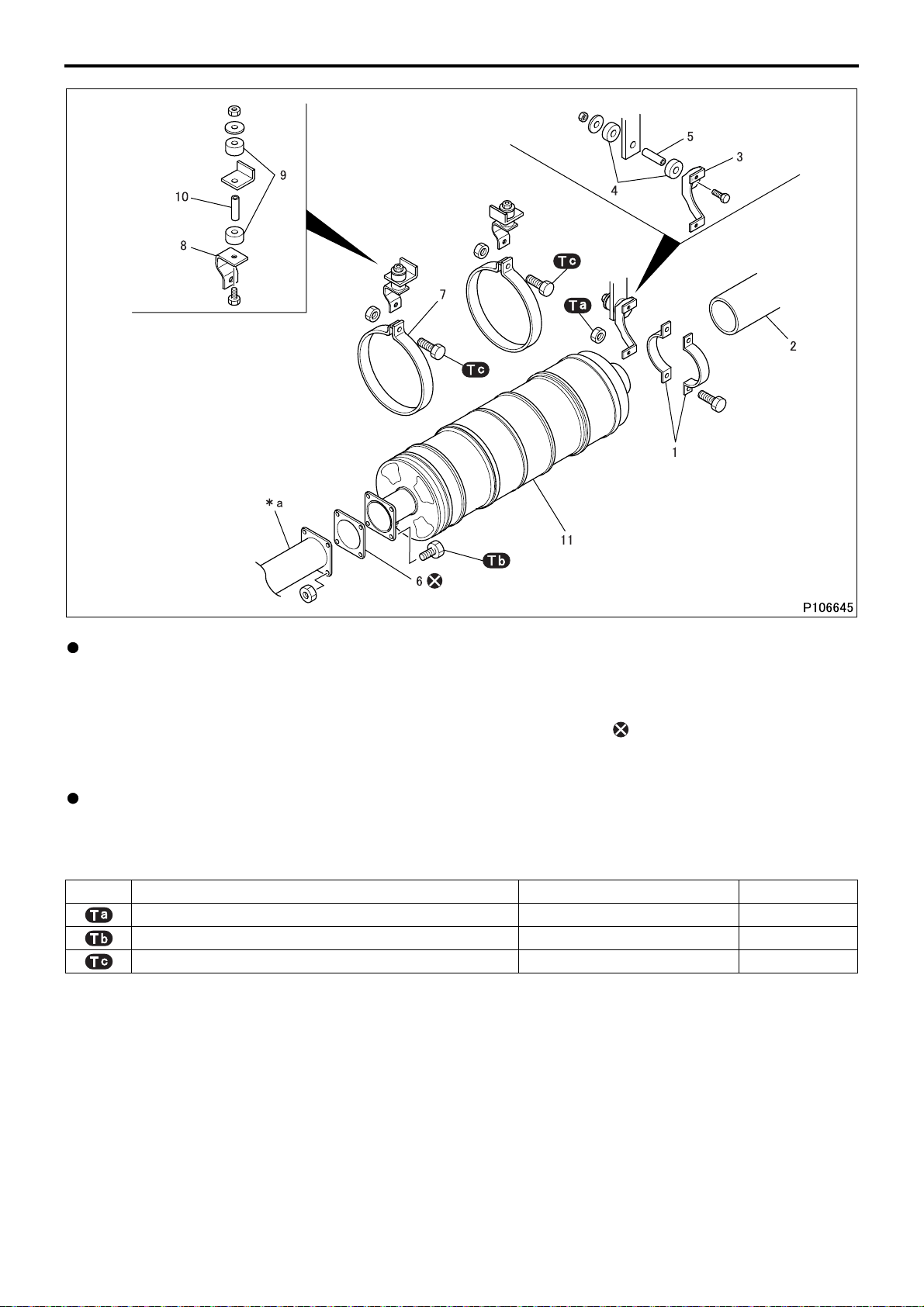
15-58
Disassembly sequence
Assembly sequence
Follow the disassembly sequence in reverse.
Tightening torque (Unit: N·m {kgf·m})
Mark Parts to be tightened Tightening torque Remarks
Nut (clamp tightening) 54
± 10 {5.5 ± 1.0} –
Nut (front pipe mounting) 85 to 110 {8.6 to 11.0} –
Bolt (clamp tightening) 20
± 3 {2.1 ± 0.3} –
1 Clamp
2 Tail pipe
3 Stay
4 Rubber cushion
5 Collar
6 Gasket
7 DPF band
8 Stay
9 Rubber cushion
10 Collar
11 DPF
*
a: Front pipe
: Non-reusable parts
DPF: Diesel Particulate Filter
DIESEL PARTICULATE FILTER <FS>
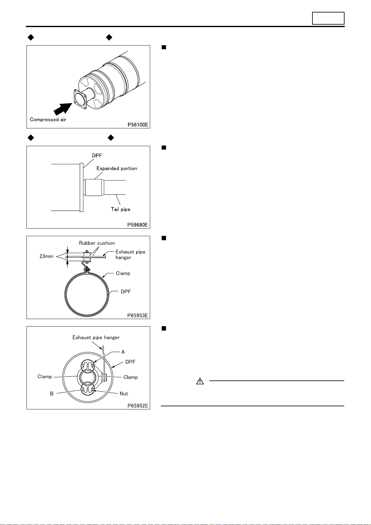
15
15-59
Inspection procedure
Inspection: DPF
• Check the inner exhaust channel of DPF for clogging with for-
eign material.
• If clogged, the inner exhaust channel must be cleaned with com-
pressed air or DPF must be replaced.
• If DPF is clogged, this may be due to problems with the engine.
Check the engine and adjust as required. Also check the engine
oil and fuel.
Installation procedure
Installation: DPF
• Insert the DPF pipe into the tail pipe until the DPF pipe bottoms
out against the expanded portion of the tail pipe.
Installation: Rubber cushions
• Compress the rubber cushions until the dimensions shown in
the illustration are achieved.
Installation: Clamps
• Tighten the nuts just enough to loosely retain the clamps so that
they can easily be moved.
• Tighten the nut at A until the ends of the clamps at A contact with
each other.
• Completely tighten the nut at B.
CAUTION
• Do not overtighten the nut at B, or the clamps and DPF may
become damaged.
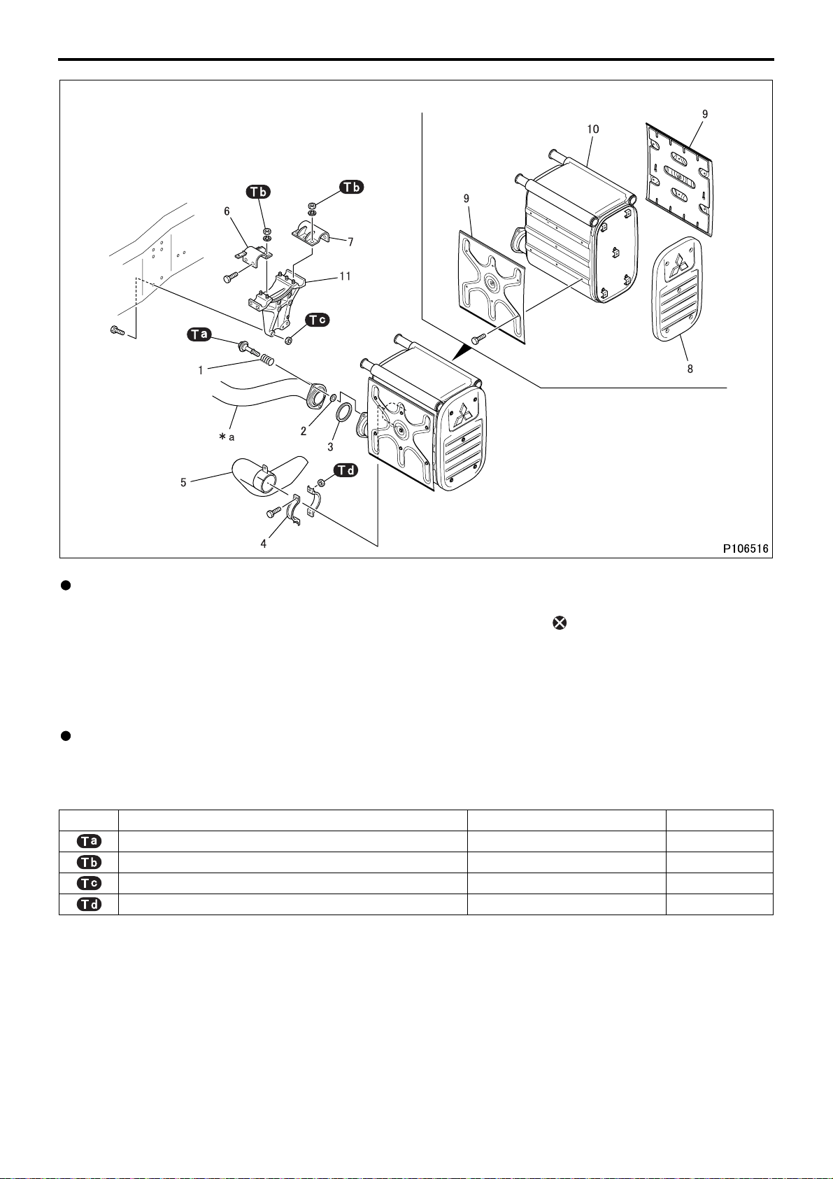
15-60
Disassembly sequence
Assembly sequence
Follow the disassembly sequence in reverse.
Tightening torque (Unit: N·m {kgf·m})
Mark Parts to be tightened Tightening torque Remarks
Bolt (front pipe mounting) 34 to 54 {3.5 to 5.5} –
Nut (DPF mounting) 70 to 95 {7.1 to 9.7} –
Nut (bracket mounting) 306 to 360 {31 to 37} –
Nut (bracket mounting) 20
± 3 {2.1 ± 0.3} –
1 Spring
2 Washer
3 Seal ring
4 Clamp
5 Tail pipe
6 Muffler plate
7 Muffler plate
8 DPF cover
9 DPF insulator
10 DPF
11 Bracket
*
a: Front pipe
: Non-reusable parts
DPF: Diesel Particulate Filter
DIESEL PARTICULATE FILTER <EXCEPT FS>
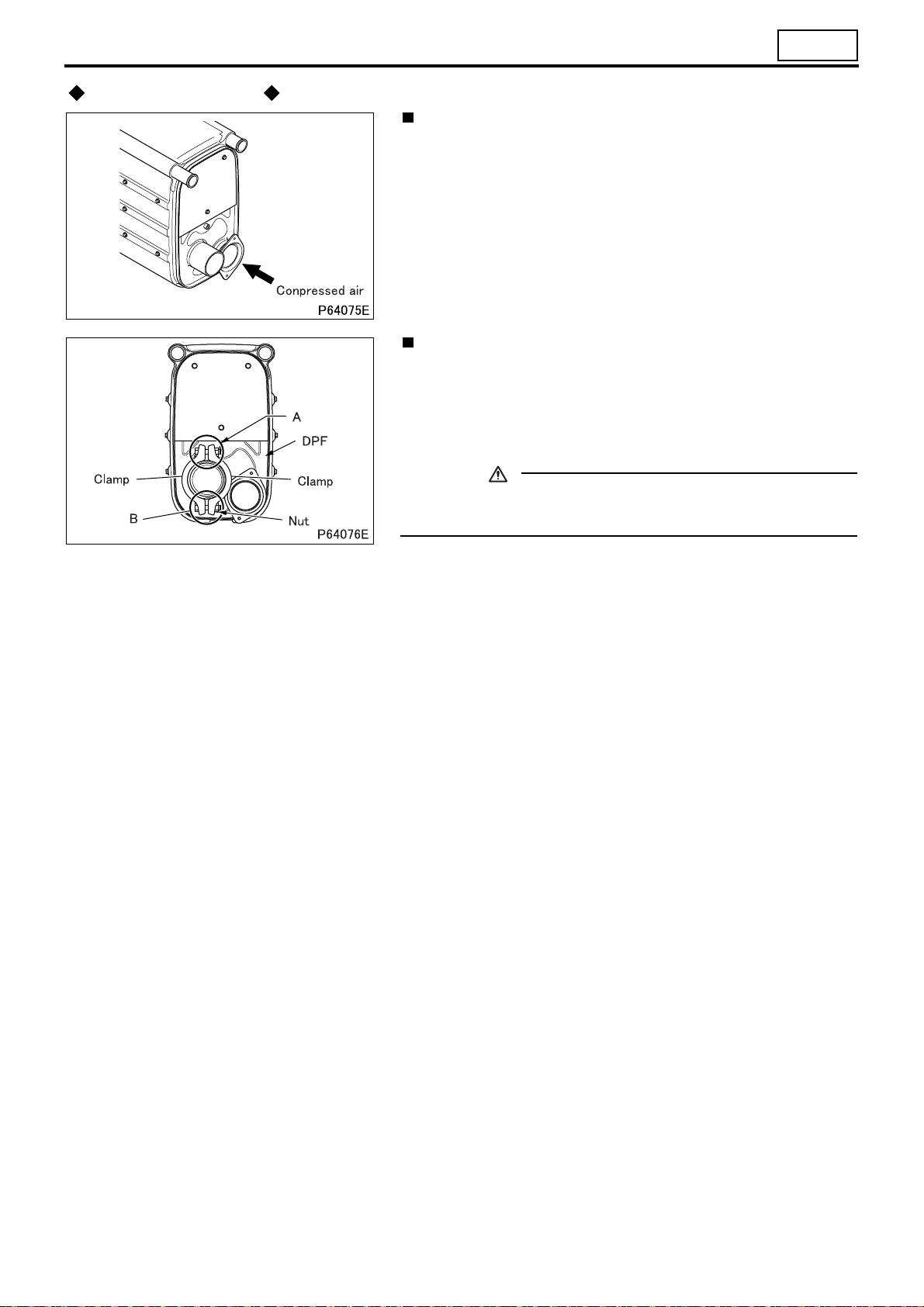
15
15-61
Inspection procedure
Inspection: DPF
• Check the inner exhaust channel of DPF for clogging with for-
eign material.
• If clogged, the inner exhaust channel must be cleaned with com-
pressed air or DPF must be replaced.
• If DPF is clogged, this may be due to problems with the engine.
Check the engine and adjust as required. Also check the engine
oil and fuel.
Installation: Clamps and rubber cushions
• Tighten the nuts just enough to loosely retain the clamps so that
they can easily be moved.
• Tighten the nut at A until the ends of the clamps at A contact with
each other.
• Completely tighten the nut at B.
CAUTION
• Do not overtighten the nut at B, or the clamps and DPF may
become damaged.

17-1
GROUP 17 MITSUISHI 6M70
EMISSION CONTROL
STRUCTURE AND OPERATION
1. Exhaust Gas Recirculation System............................................... 17-2
2. Blowby Gas Return System .......................................................... 17-7
ON-VEHICLE INSPECTION AND ADJUSTMENT
1. Replacement of Positive Crankcase Ventilation Valve Element..... 17-8
2. Check for Cracks and Damages in Piping of Blowby Gas
Retu
rn System
.............................................................................. 17-8
3. Check for Cracks, Damages and Looseness in Piping of
Exhaust Gas Recirculation System
............................................... 17-8
EXHAUST GAS RECIRCULATION SYSTEM
1. Diagnosis Procedure .................................................................. 17-10
2. Diagnostic Precautions .............................................................. 17-10
3. Inspections Based on Diagnosis Codes ......................................17-11
4. Multi-Use Tester Service Data ..................................................... 17-14
5. Actuator Tests Performed Using Multi-Use Tester....................... 17-14
6. Inspections Performed at Electronic Control Unit Connectors.... 17-14
7. Inspection of Electrical Equipment ............................................. 17-16
8. Installed Locations of Parts ........................................................ 17-18
9. Electric Circuit Diagram.............................................................. 17-24
EGR VALVE, EGR MAGNETIC VALVE, EGR PIPE AND
EGR COOLER................................................................................... 17-26
BLOWBY GAS RETURN SYSTEM .................................................. 17-29
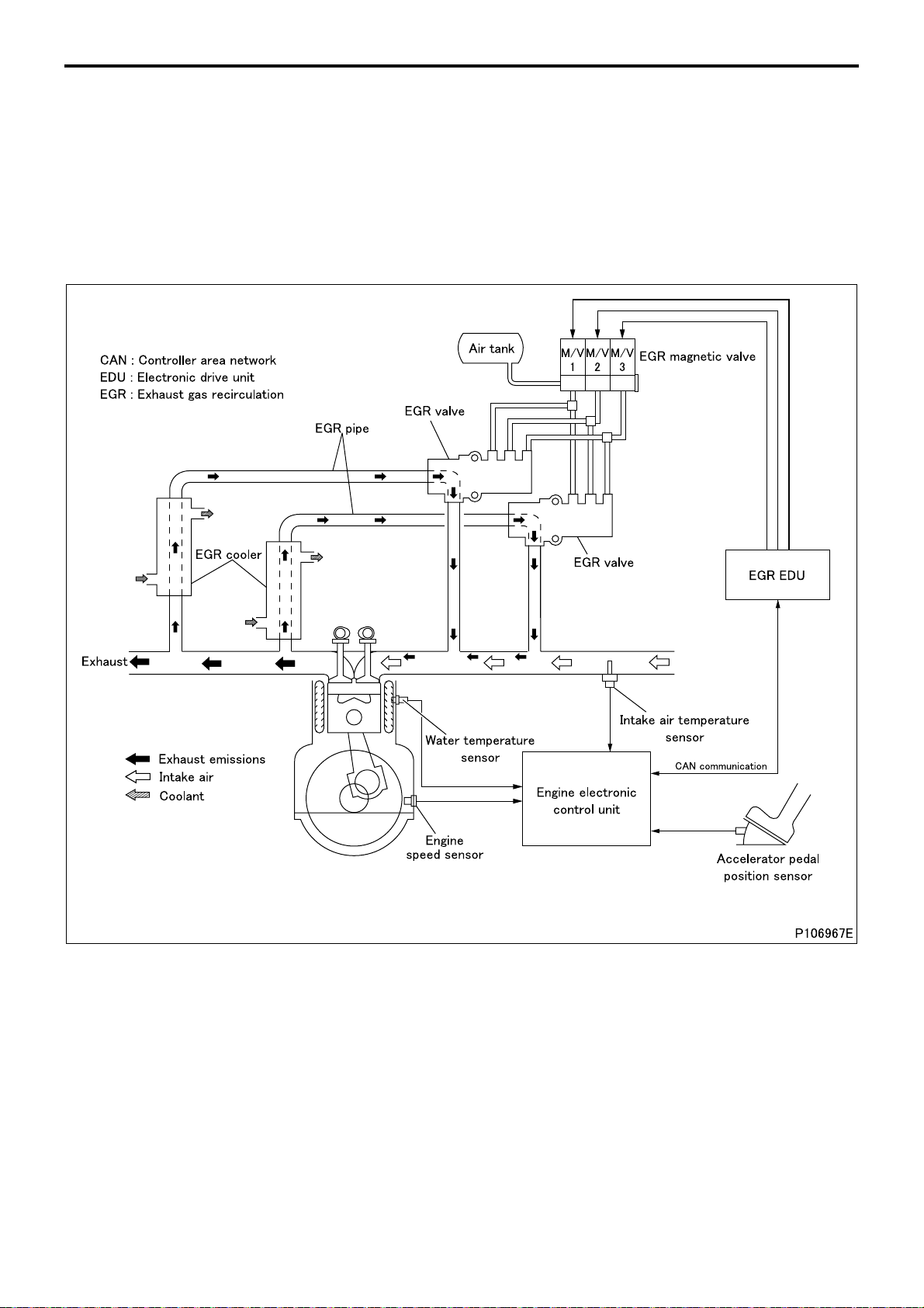
17-2
1. Exhaust Gas Recirculation System
1.1 Overview
• In the exhaust gas recirculation system, various engine-related information (engine speed, water temperature, ac-
celerator position) is collected by the relevant sensors and is sent to the engine electronic control unit and EGR
EDU which then control the EGR magnetic valves based on the information received.
• EGR achieves lower combustion temperatures by reintroducing combusted exhaust gas (which contains inert
gases) into the intake manifold. This has the effect of reducing the amount of harmful NOx (nitrogen oxides)
formed in the engine. The EGR cooler enhances the NOx (nitrogen oxides) reducing performance of the EGR
system by cooling the mixed exhaust gas to lower maximum combustion temperature.
STRUCTURE AND OPERATION
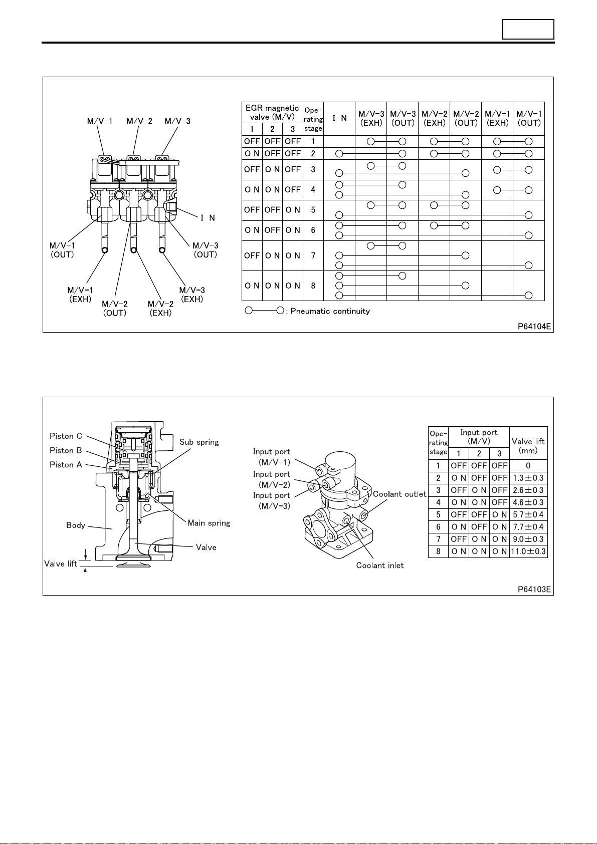
17
17-3
(1) EGR magnetic valves
• The EGR magnetic valves are each turned ON/OFF by drive signals from the engine electronic control unit to re-
alize a 7-stage supply of air to the EGR valve.
(2) Mitsubishi 6M70 EGR valve
• The EGR valve realizes 7 stages of valve lift in accordance with the supply of air to its input ports from the EGR
magnetic valves.
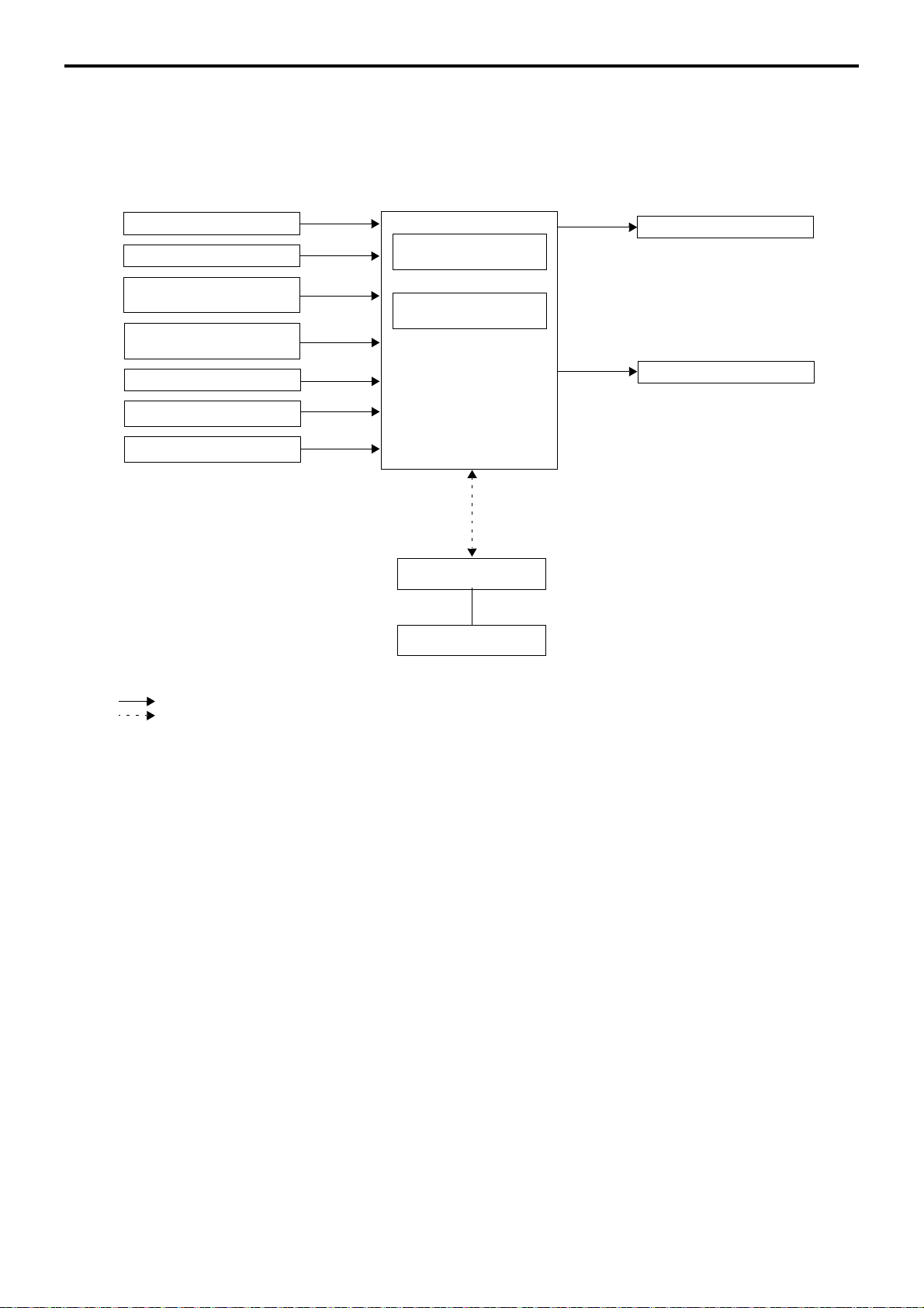
17-4
1.2 Electronic control system
(1) System block diagram
Input signals
Engine electronic control unit
Output signals
Exhaust gas recircula-
tion control function
Engine speed sensor
Water temperature sensor
Accelerator pedal position
sensor
Fault diagnosis
function
Engine warning lamp
Electronic drive unit relay
EGR: Exhaust gas recirculation
EDU: Electronic drive unit
Memory clear switch
Multi-Use Tester connector
Diagnosis switch
Intake air temperature
sensor
: Electrical signal
: Controller area network signal
EGR EDU
EGR magnetic valve
STRUCTURE AND OPERATION

17
17-5
(2) Exhaust gas recirculation valve control function
• Based on inputs from various sensors, the engine electronic control unit determines the degree of opening of the
exhaust gas recirculation valve and sends corresponding control signals to the exhaust gas recirculation electron-
ic drive unit to activate the exhaust gas recirculation magnetic valve.
In the case of black smoke emission or engine speed instability, which may occur when the engine is heavily load-
ed or lightly loaded, or when the auxiliary brake is operating, the engine electronic control unit stops exhaust gas
recirculation valve control.
(3) Fault diagnosis function
• While the starter switch is in the ON position, the engine electronic control unit continuously monitors exhaust gas
recirculation electronic drive unit, the sensors and other control elements for faults. In the event that the engine
electronic control unit finds a component faulty, it causes an indication to be made in the meter cluster to alert the
driver. At the same time, it memorizes the fault location in the form of a diagnosis code.
• While the engine is running, the exhaust gas recirculation electronic drive unit continuously monitors the status of
communication with the exhaust gas recirculation magnetic valve and engine electronic control unit. When the ex-
haust gas recirculation electronic drive unit detects a fault, it sends the information to the engine electronic control
unit.
• While the control during fault is taking place, the system’s functionality is limited to ensure vehicle and driver safe-
ty. It is possible to read the memorized diagnosis code using a Multi-Use Tester or from flashing of the warning
lamp.
• Diagnosis codes shown by the Multi-Use Tester and those indicated by flashing of the warning lamp are different.
• The Multi-Use Tester is capable of showing more detailed diagnosis codes.
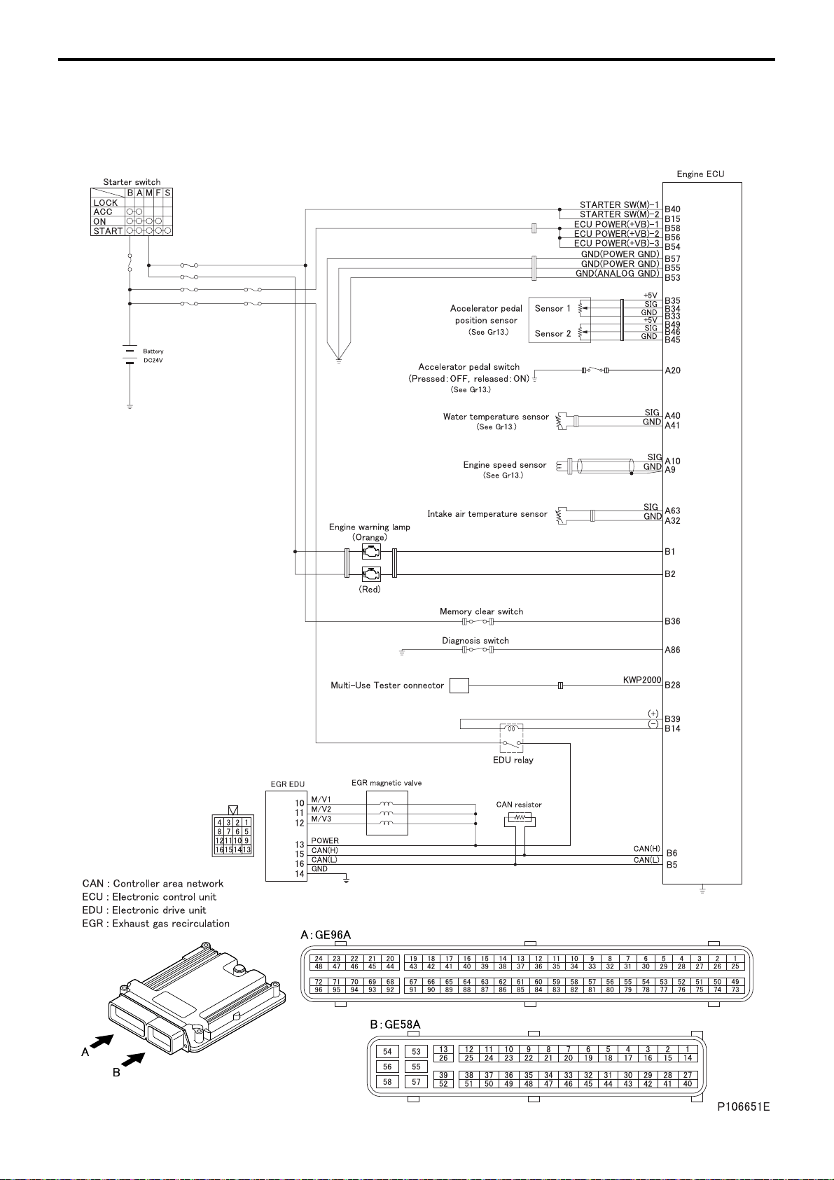
17-6
1.3 Electronic control unit connection diagram
STRUCTURE AND OPERATION
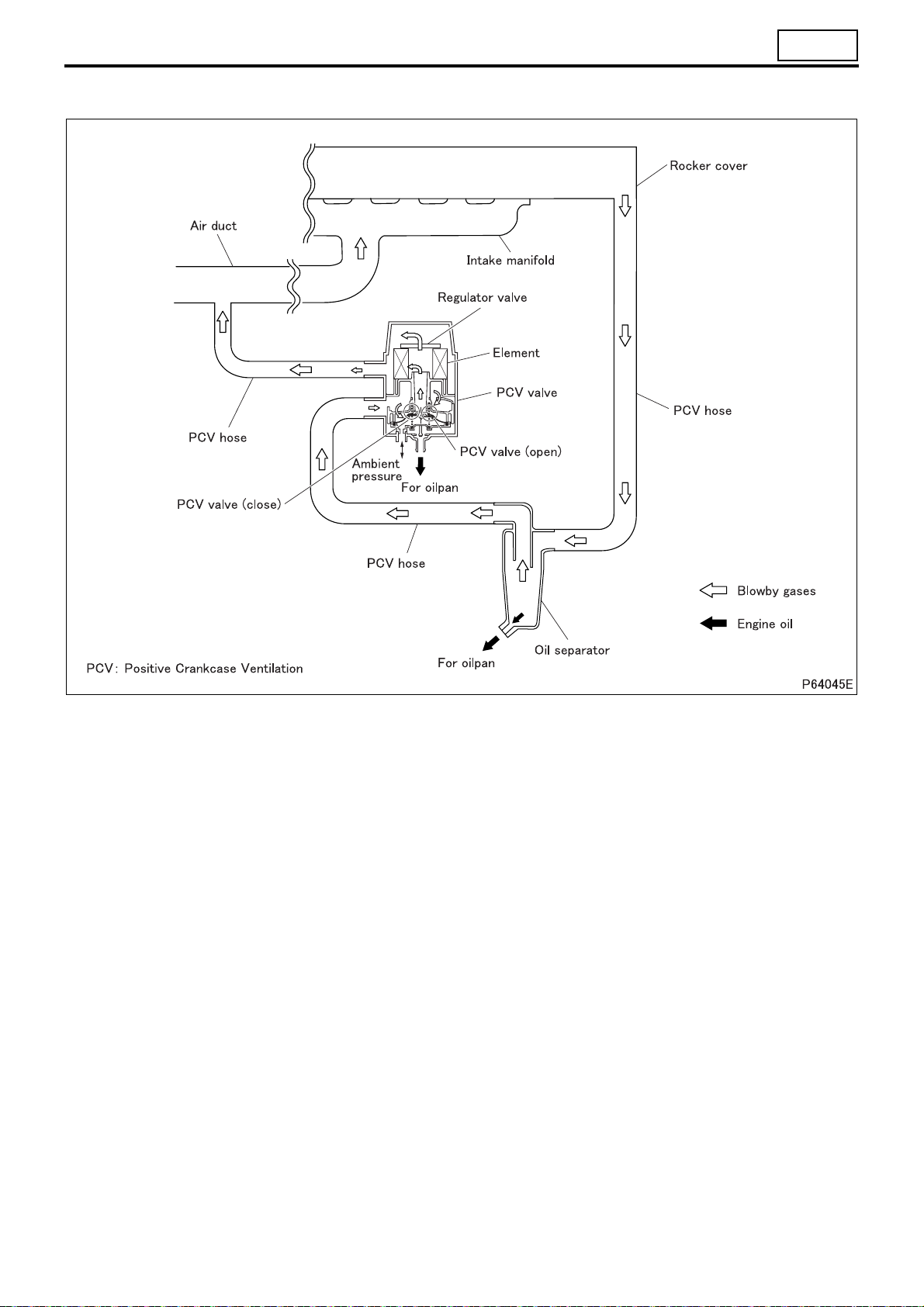
17
17-7
2. Blowby Gas Return System
• The blowby gas return system is designed to introduce blowby gases into the intake air duct for reburning, thus
preventing the gases from being released to the atmosphere.
• The positive crankcase ventilation valve keeps constant the pressure inside the crankcase.
• The oil in the blowby gas is separated by the wire mesh and the element in the oil separator and the positive
crankcase ventilation valve and is returned to the oil pan.
• When the element is clogged, the regulator valve opens and the blowby gas flows to the positive crankcase venti-
lation hose without passing through the element.
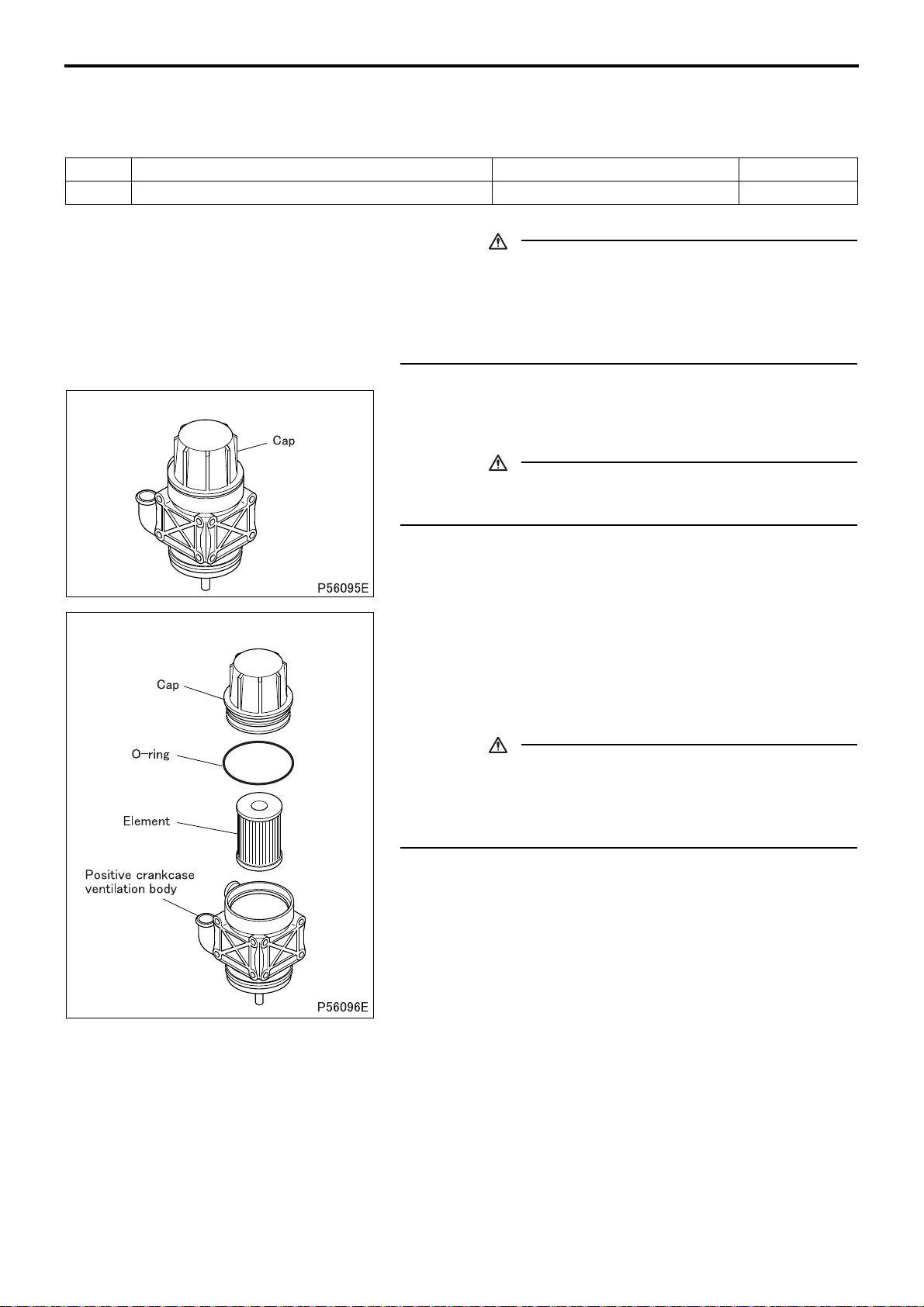
17-8
1. Replacement of Positive Crankcase Ventilation Valve Element
Lubricant and/or sealant
CAUTION
• For information on the element replacement interval, refer
to the element instruction manual. If the element is used be-
yond its replacement interval, it may become clogged,
causing the pressure inside the engine to increase such
that oil leakage occurs.
[Removal]
• Loosen the cap by hand.
CAUTION
• Do not use any tools to loosen the cap. Otherwise, the cap
may become damaged.
[Installation]
• Clean the thread on the cap.
• Lightly smear the O-ring with engine oil and fit it on the cap.
• Securely tighten the cap until it stops slightly above the positive
crankcase ventilation body.
CAUTION
• Be sure to use a genuine Mitsubishi Fuso element. Using an
inappropriate element could result in engine trouble.
• When replacing the element, be sure to replace the O-ring
also.
2. Check for Cracks and Damages in Piping of Blowby Gas Return System
• Inspect the piping of blowby gas return system visually. If there is any cracks or damages, replace the piping.
(See “BLOWBY GAS RETURN SYSTEM”.)
3. Check for Cracks, Damages and Looseness in Piping of Exhaust Gas Recircula-
tion System
• Inspect the exhaust gas recirculation pipe visually. If there is any cracks or damages, replace the pipe. (See “EGR
VALVE, EGR PIPE AND EGR COOLER”.)
• Check for looseness in the exhaust gas recirculation pipe mounting bolts and nuts. If there is looseness, tighten
the bolts and nuts to the specified torque. (See “EGR VALVE, EGR PIPE AND EGR COOLER”.)
Mark Points of application Specified lubricant and/or sealant Quantity
– O-ring Engine oil As required
ON-VEHICLE INSPECTION AND ADJUSTMENT

M E M O
17-9
17

17-10
1. Diagnosis Procedure
• Perform the inspection in accordance with the following flowchart.
2. Diagnostic Precautions
• Before measuring voltage, check the battery for charged condition and specific gravity. If system inspection is per-
formed with the battery uncharged or reduced in specific gravity, accurate measurements cannot be achieved.
• Before disconnecting battery cables, harnesses and connectors, set the starter switch to LOCK or OFF, then allow
at least 20 seconds.
• To avoid having electrical parts damaged, set the starter switch and lighting switch to LOCK or OFF before recon-
necting battery cables, harnesses and connectors.
• When performing measurement with the tester, handle the test bar carefully so that it does not damage internal
circuit and other electrical parts of the electronic control unit to result in a short-circuit failure between terminals in
connector or between connector and car body
.
• Re
sistance is affected by temperature. Determine the necessity of resistance measurement following given tem-
perature specification as a guide. Otherwise, use normal temperature (10 to 35°C) as the measuring condition.
Vehicle in service shop
Read all (past and present) diagnosis codes by Multi-Use Tester. (See Gr00.)
Warning lamp lit
Was able to identify the fault?
Response to transient fault
(See Gr00.)
Perform inspection based on diagnosis codes. (See later section.)
Rectify or replace with new parts.
Clear stored diagnosis code. (See Gr00.)
Read diagnosis code(s) by Multi-Use Tester. (See Gr00.)
Code issued
End of inspection
Tes t d r i v e
NO
YES
No code issued
EXHAUST GAS RECIRCULATION SYSTEM
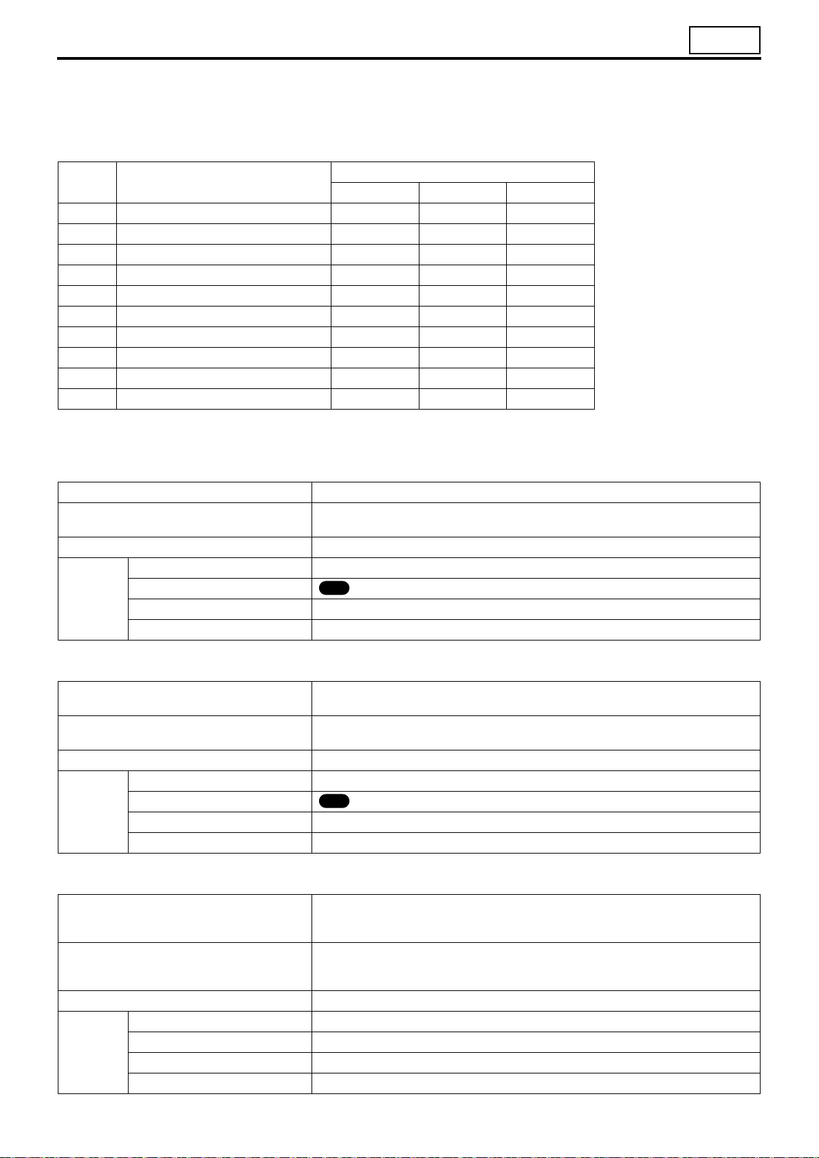
17
17-11
3. Inspections Based on Diagnosis Codes
3.1 Diagnosis code list
• Diagnosis codes shown by the Multi-Use Tester and those indicated by warning lamp display are different.
• The Multi-Use Tester is capable of showing more detailed diagnosis codes.
3.2 Diagnosis code generation conditions and inspection items
P0112: INT Air Temp SNSR (Low) (warning lamp flashes: 44)
P0113: INT Air Temp SNSR (High) (warning lamp flashes: 44)
P1267: EGR1 (warning lamp: 67)
Code Message
Warning lamp indication
Flashes Red Orange
P0112 INT Air Temp SNSR (Low) 44 – O
P0113 INT Air Temp SNSR (High) 44 – O
P1267 EGR 1 67 – O
P1268 EGR 1 67 – O
P1272 EGR 2 68 – O
P1273 EGR 2 68 – O
P1277 EGR 3 69 – O
P1278 EGR 3 69 – O
P1625 EDU Relay 84 – O
P1630 CAN (EGR 1) 95 – O
Generation condition Intake air temperature sensor 1 voltage remains lower than 0.15 V for 3 seconds.
Recoverability
System recovers if intake air temperature sensor 1 voltage remains higher than
0.15 V for 1 second.
Control effected by electronic control unit Carries out control using a backup value (25°C).
Inspection
Service data 2B: Intake Air Temperature
Electronic control unit connector : Intake air temperature sensor 1
Electrical equipment #305: Intake air temperature sensor
Electric circuit diagram Intake air temperature sensor 1 system
Generation condition
Intake air temperature sensor 1 voltage remains higher than 4.85 V for 3 sec-
onds.
Recoverability
System recovers if intake air temperature sensor 1 voltage remains lower than
4.85 V for 1 second.
Control effected by electronic control unit Carries out control using a backup value (25°C).
Inspection
Service data 2B: Intake Air Temperature
Electronic control unit connector : Intake air temperature sensor 1
Electrical equipment #305: Intake air temperature sensor
Electric circuit diagram Intake air temperature sensor 1 system
Generation condition
Controller area network signal from exhaust gas recirculation electronic drive unit
indicating “magnetic valve (M/V-1) circuit shorted to ground or open” remains be-
ing received for 2 seconds.
Recoverability
System recovers if controller area network signal from exhaust gas recirculation
electronic drive unit indicating “magnetic valve (M/V-1) is normal” remains being
received for 1 second.
Control effected by electronic control unit Exhaust gas recirculation control is stopped.
Inspection
Service data 20: Actual EGR Position
Actuator test A1: EGR1
Electrical equipment #530: Exhaust gas recirculation magnetic valve
Electric circuit diagram Exhaust gas recirculation magnetic valve system
01
01
17-12
P1268: EGR1 (warning lamp: 67)
P1272: EGR2 (warning lamp: 68)
P1273: EGR2 (warning lamp: 68)
P1277: EGR3 (warning lamp: 69)
Generation condition
Controller area network signal from exhaust gas recirculation electronic drive unit
indicating “magnetic valve (M/V-1) circuit shorted to power source” remains being
received for 2 seconds.
Recoverability
System recovers if controller area network signal from exhaust gas recirculation
electronic drive unit indicating “magnetic valve (M/V-1) is normal” remains being
received for 1 second.
Control effected by electronic control unit Exhaust gas recirculation control is stopped.
Inspection
Service data 20: Actual EGR Position
Actuator test A1: EGR1
Electrical equipment #530: Exhaust gas recirculation magnetic valve
Electric circuit diagram Exhaust gas recirculation magnetic valve system
Generation condition
Controller area network signal from exhaust gas recirculation electronic drive unit
indicating “magnetic valve (M/V-2) circuit shorted to ground or open” remains be-
ing received for 2 seconds.
Recoverability
System recovers if controller area network signal from exhaust gas recirculation
electronic drive unit indicating “magnetic valve (M/V-2) is normal” remains being
received for 1 second.
Control effected by electronic control unit Exhaust gas recirculation control is stopped.
Inspection
Service data 20: Actual EGR Position
Actuator test A2: EGR2
Electrical equipment #530: Exhaust gas recirculation magnetic valve
Electric circuit diagram Exhaust gas recirculation magnetic valve system
Generation condition
Controller area network signal from exhaust gas recirculation electronic drive unit
indicating “magnetic valve (M/V-2) circuit shorted to power source” remains being
received for 2 seconds.
Recoverability
System recovers if controller area network signal from exhaust gas recirculation
electronic drive unit indicating “magnetic valve (M/V-2) is normal” remains being
received for 1 second.
Control effected by electronic control unit Exhaust gas recirculation control is stopped.
Inspection
Service data 20: Actual EGR Position
Actuator test A2: EGR2
Electrical equipment #530: Exhaust gas recirculation magnetic valve
Electric circuit diagram Exhaust gas recirculation magnetic valve system
Generation condition
Controller area network signal from exhaust gas recirculation electronic drive unit
indicating “magnetic valve (M/V-3) circuit shorted to ground or open” remains be-
ing received for 2 seconds.
Recoverability
System recovers if controller area network signal from exhaust gas recirculation
electronic drive unit indicating “magnetic valve (M/V-3) is normal” remains being
received for 1 second.
Control effected by electronic control unit Exhaust gas recirculation control is stopped.
Inspection
Service data 20: Actual EGR Position
Actuator test A3: EGR3
Electrical equipment #530: Exhaust gas recirculation magnetic valve
Electric circuit diagram Exhaust gas recirculation magnetic valve system
EXHAUST GAS RECIRCULATION SYSTEM
17
17-13
P1278: EGR3 (warning lamp: 69)
P1625: EDU Relay (warning lamp flashes: 84)
P1630: CAN (EGR 1) (warning lamp flashes: 95)
Generation condition
Controller area network signal from exhaust gas recirculation electronic drive unit
indicating “magnetic valve (M/V-3) circuit shorted to power source” remains being
received for 2 seconds.
Recoverability
System recovers if controller area network signal from exhaust gas recirculation
electronic drive unit indicating “magnetic valve (M/V-3) is normal” remains being
received for 1 second.
Control effected by electronic control unit Exhaust gas recirculation control is stopped.
Inspection
Service data 20: Actual EGR Position
Actuator test A3: EGR3
Electrical equipment #530: Exhaust gas recirculation magnetic valve
Electric circuit diagram Exhaust gas recirculation magnetic valve system
Generation condition
Either of the following occurs.
(1) Current flowing in the electronic drive unit relay remains exceeds the speci-
fied value for 1 second.
(2) Electronic drive unit relay circuit remains shorted to ground or open (driving
terminal low level when turned OFF) as detected for 1 second.
(3) Electronic drive unit relay circuit remains shorted to power supply (high level
when turned ON) as detected for 1 second.
Recoverability
• In the case of above problem (1)
• System recovers if current flowing in the electronic drive unit relay remains
lower than the specified value.
• In the case of above problem (2)
• System recovers if current flowing in the electronic drive unit relay remains
normal (driving terminal high level when turned OFF) for 1 second.
• In the case of above problem (3)
• System recovers if current flowing in the electronic drive unit relay remains
normal (driving terminal low level when turned ON) for 1 second.
Control effected by electronic control unit Exhaust gas recirculation control is stopped.
Inspection
Service data 89: EDU Power Relay
Actuator test B2: EDU Relay
Electronic control unit connector : Electronic drive unit relay
Electrical equipment #201: Inspection of relay
Electric circuit diagram Electronic drive unit relay system
Generation condition
Any of the following occurs.
(1) Controller area network signal from exhaust gas recirculation electronic drive
unit 1 indicating “target exhaust gas recirculation opening received from en-
gine electronic control unit is wrong” remains being received for 2 seconds.
(2) No controller area network signal from exhaust gas recirculation electronic
drive unit is received for 1 second.
(3) Engine controller area network signal abnormal state lasts for 0.5 second.
Recoverability
• In the case of above problem (1)
• System recovers if controller area network signal from exhaust gas recircu-
lation electronic drive unit 1 indicating “target exhaust gas recirculation
opening received from engine electronic control unit is normal” remains be-
ing received for 1 second.
• In the case of above problem (2)
• System recovers if controller area network signal from exhaust gas recircu-
lation electronic drive unit remains being received for 0.5 second.
• In the case of above problem (3)
• System recovers if normal engine controller area network signal lasts for
0.5 second.
Control effected by electronic control unit Exhaust gas recirculation control is stopped.
Inspection
Service data 20: Actual EGR Position 1
Actuator test A1: EGR 1
Electrical equipment Exhaust gas recirculation electronic drive unit and engine electronic control unit
Electric circuit diagram
Controller area network communication system between engine electronic con-
trol unit and exhaust gas recirculation electronic drive unit
02
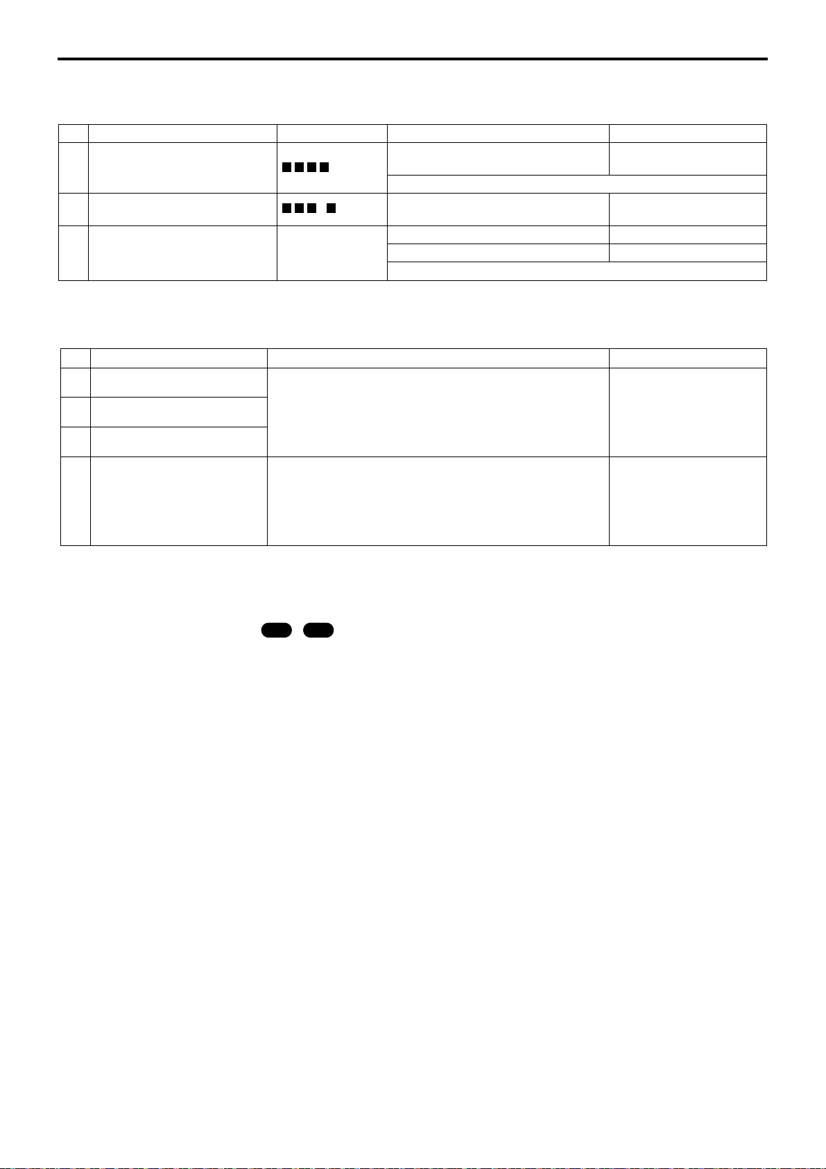
17-14
4. Multi-Use Tester Service Data
• It is possible to see service data and actuator tests simultaneously.
5. Actuator Tests Performed Using Multi-Use Tester
• It is possible to see service data and actuator tests simultaneously.
6. Inspections Performed at Electronic Control Unit Connectors
• These inspections aid troubleshooting by enabling you to check whether electronic control unit signals are being
correctly transmitted via the vehicle harness and connectors.
The white-on-black numbers ( , , and so on) correspond to the similarly printed reference numbers in
section “3. Inspections Based on Diagnosis Codes”.
No. Item Data Inspection condition Requirement
20 Actual EGR Position .
Perform actuator test
Position as commanded by
actuator test
[Actuator test] A1: EGR 1
2B Intake Air Temperature . °C On a cold engine
Equal to ambient tempera-
ture
89 EDU Power Relay ON/OFF
Starter switch ON ON
Starter switch OFF OFF
[Actuator test] B2: EDU relay
No. Item Explanation Confirmation method
A0 EGR 1
Maintain exhaust gas recirculation valve 1 opening indicated
by Multi-Use Tester.
[Can be executed when the following conditions are satisfied]
• Vehicle: stationary (vehicle speed 0 km/h)
• Starter switch: ON
• Engine: stopped
Actual position of service
data matches target value
commanded by actuator
test
[Service data]
20: Actual EGR Position
A1 EGR 2
A3 EGR 3
AC EDU Relay
ON/OFF switchover of electronic drive unit relay
(automatically reset after 15 seconds)
[Can be executed when the following conditions are satisfied]
• Vehicle: stationary (vehicle speed 0 km/h)
• Starter switch: ON
• Engine: stopped
Operating sound of elec-
tronic drive unit relay
[Service data]
89: EDU Power Relay
01 02
EXHAUST GAS RECIRCULATION SYSTEM
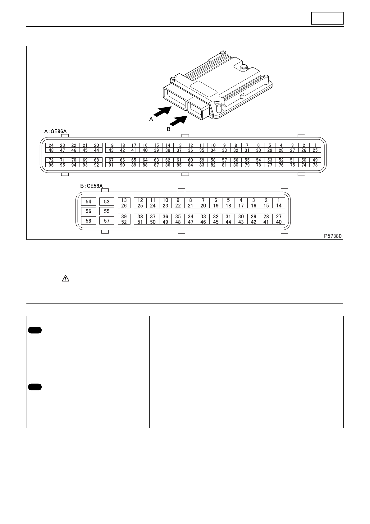
17
17-15
6.1 Electronic control unit connector terminal layout
6.2 Inspection instructions
• Some inspections are performed with the connectors removed. Others are performed with the connectors fitted.
Observe the following caution:
CAUTION
• Do not touch any terminal except those specified for the inspection. Be particularly careful not to cause
short circuits between terminals using the tester probes.
Check item Measurement method
Resistance of intake air temperature sensor 1
[Conditions]
• Starter switch OFF
• Disconnect connector. Perform inspection on vehicle-side connector.
[Requirements]
Terminals: A63-A32
• 0°C: 15 kΩ
• 20°C: 6.514 kΩ
• 80°C: 0.874 kΩ
Voltage of electronic drive unit relay
[Conditions]
• Starter switch ON
• Vehicle-side harness connected (Perform inspection on back of connector.)
[Requirements]
Terminals (+)-(–): B14-ground
• With relay operating: 0 V
• With relay not operating: Corresponding to battery voltage
01
+3.78
–2.94
+1.437
–1.147
+0.136
–0.115
02
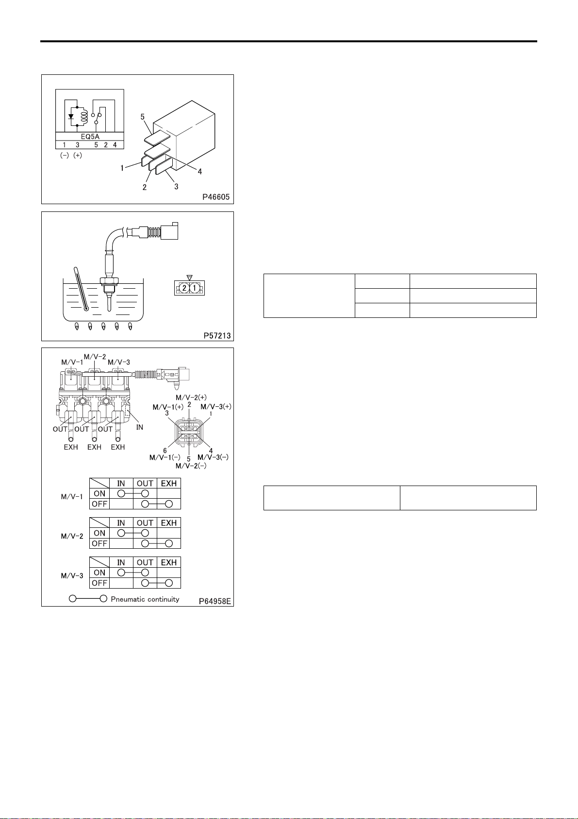
17-16
7. Inspection of Electrical Equipment
#201 Inspection of relay (normally open, 5 pins)
• Perform a continuity check and an operation check. If there is
any abnormality, replace the relay.
#305 Inspection of intake air temperature sensor
• Place the sensor in a container filled with engine oil.
• Heat the oil to each of the specified temperatures. Stir the oil
well while doing so.
• Measure the resistance between terminals 1 and 2.
• If either measurement is out of specification, replace the sensor.
#530 Inspection of exhaust gas recirculation magnetic valve
• Perform the following checks. If there is any abnormality, replace
the exhaust gas recirculation magnetic valve.
(1) Check of operation
• Gradually increase from zero the voltage applied to terminals 3
and 6 (magnetic valve 1), 2 and 5 (magnetic valve 2) and 1 and
4 (magnetic valve 3).
• Observe the voltage when the exhaust gas recirculation magnet-
ic valve operates.
(Determine the magnetic valve’s OFF-ON operation from the op-
erating sound.)
(2) Check of continuity and airtightness
• Air pressure applied during check: 930 kPa {9.5 kgf/cm
2
}
Standard value
0°C15 kΩ
20°C6.514 kΩ
80°C0.874 kΩ
Standard value
(min. operating voltage)
18 V or lower
+3.78
–2.94
+1.437
–1.147
+0.136
–0.115
EXHAUST GAS RECIRCULATION SYSTEM

M E M O
17-17
17
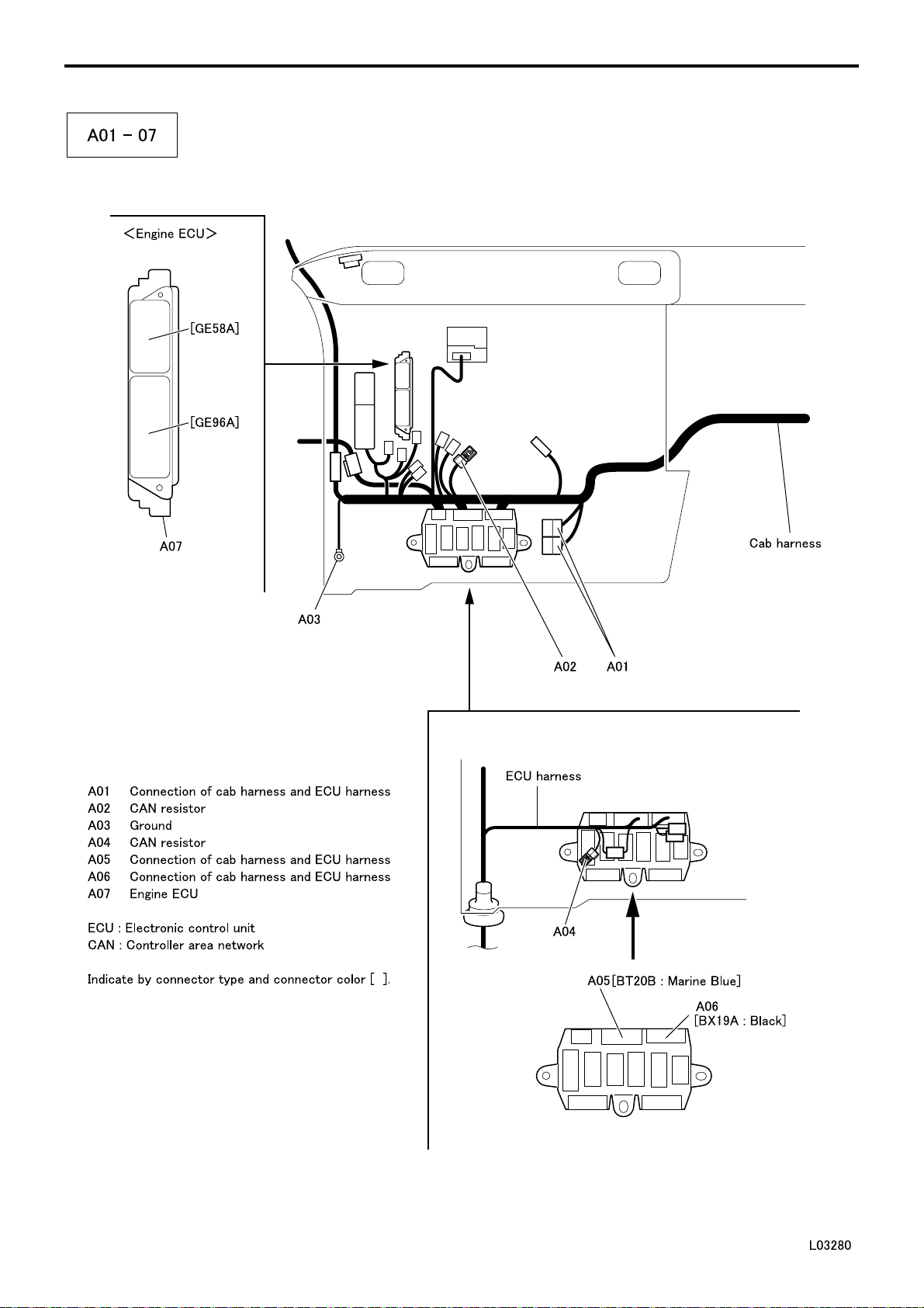
17-18
8. Installed Locations of Parts
EXHAUST GAS RECIRCULATION SYSTEM
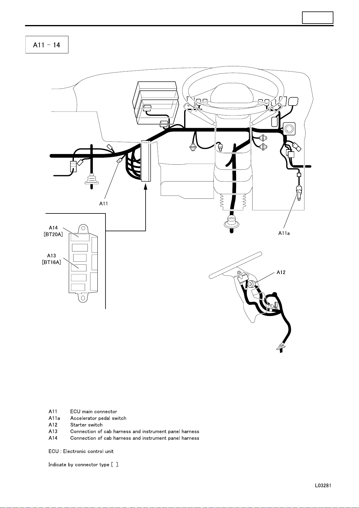
17
17-19
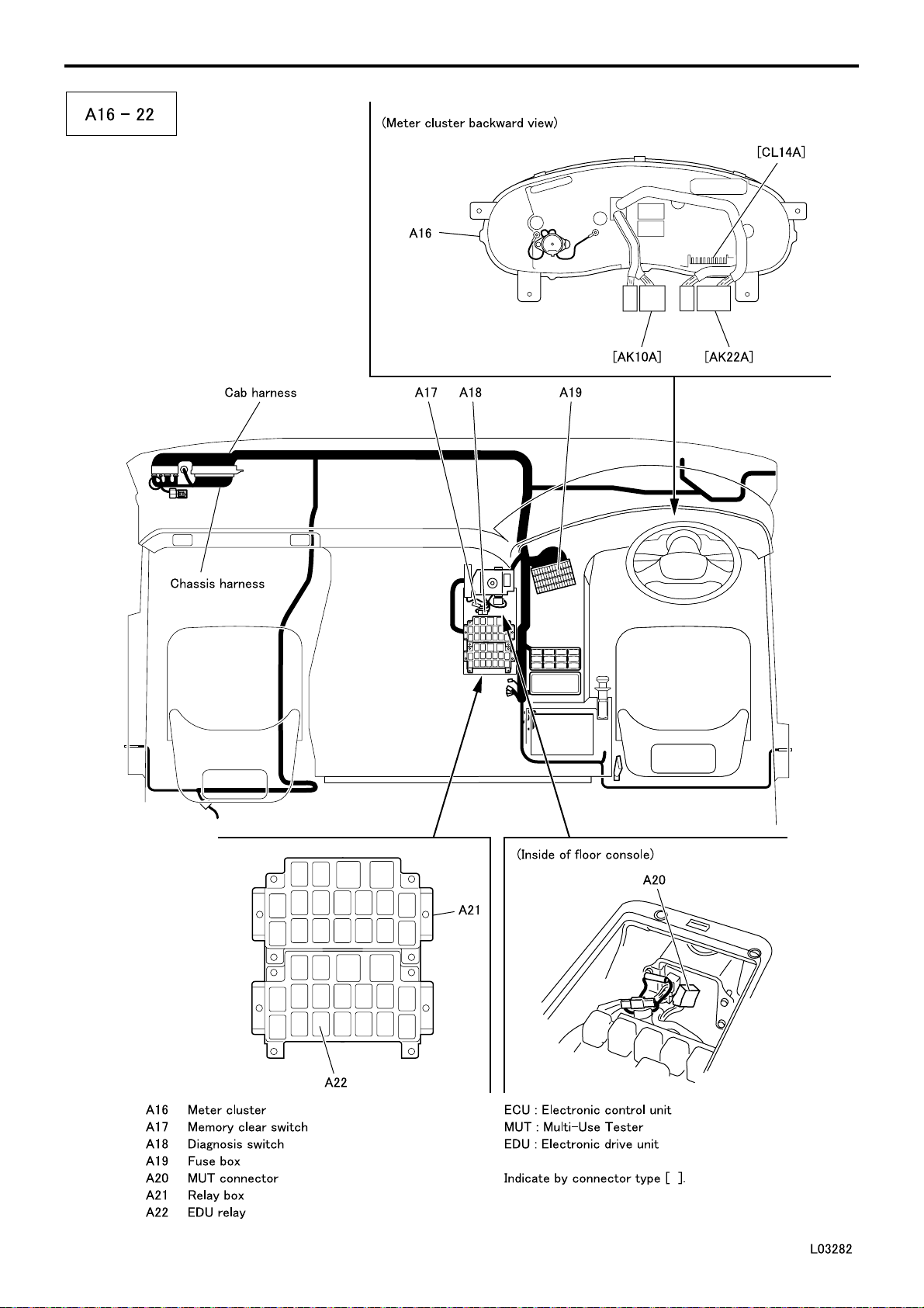
17-20
EXHAUST GAS RECIRCULATION SYSTEM
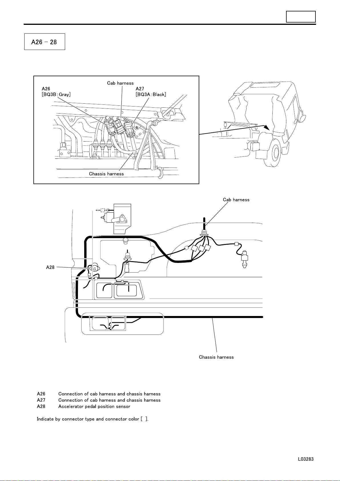
17
17-21
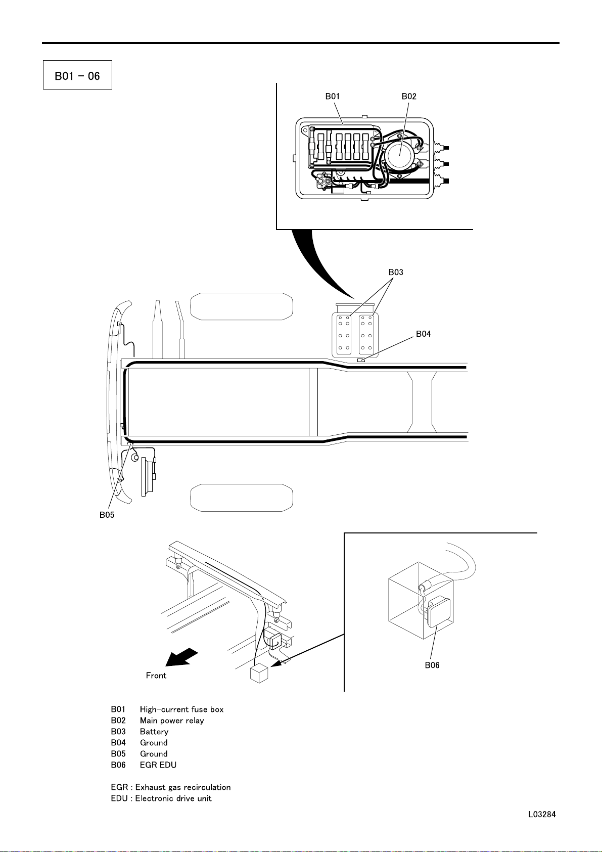
17-22
EXHAUST GAS RECIRCULATION SYSTEM
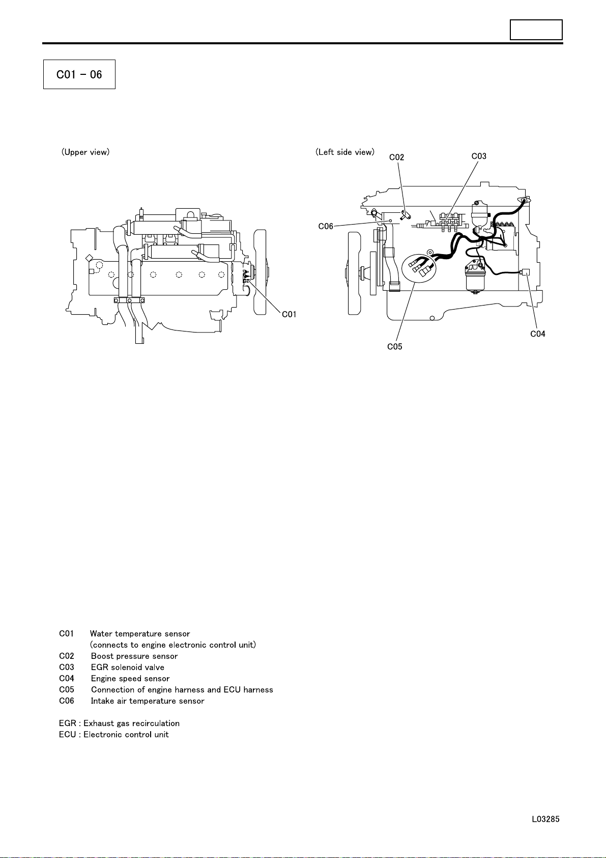
17
17-23
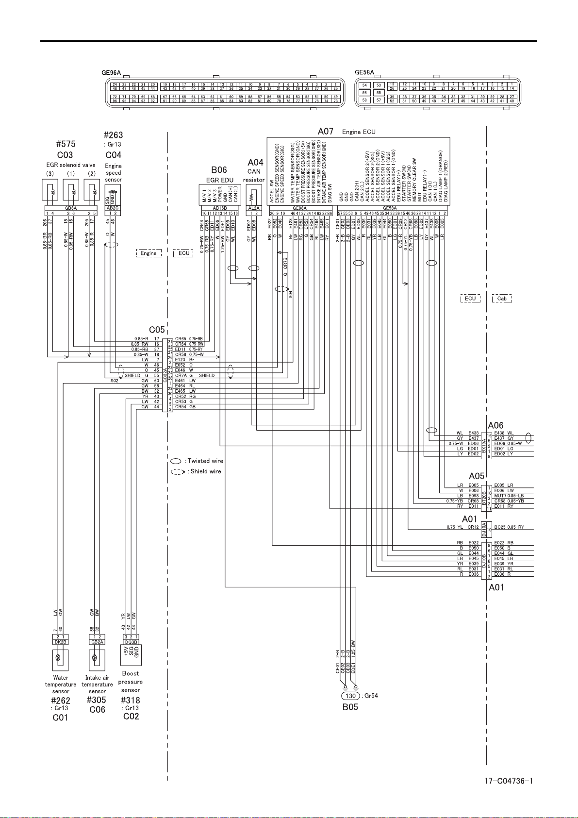
17-24
9. Electric Circuit Diagram
EXHAUST GAS RECIRCULATION SYSTEM
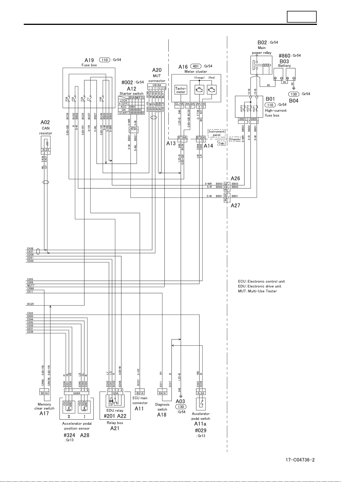
17
17-25
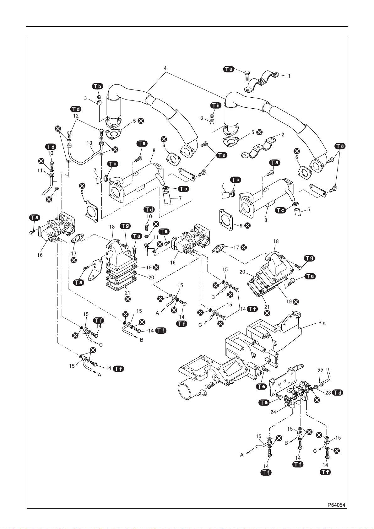
17-26
MITSUBISHI 6M70 EGR VALVE, EGR MAGNETIC VALVE, EGR PIPE
AND EGR COOLER
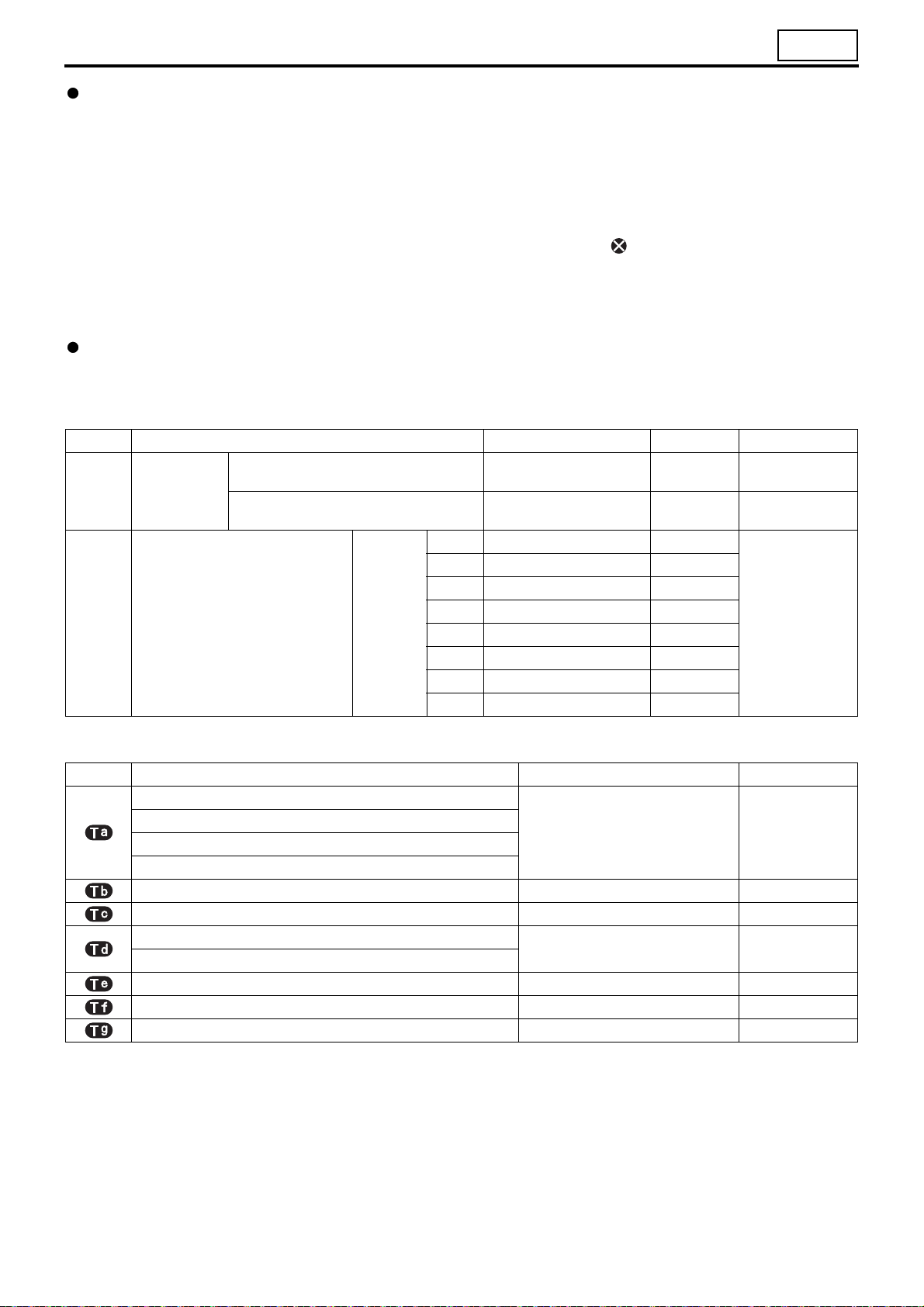
17
17-27
Removal sequence
Installation sequence
Perform installation by following the removal sequence in reverse.
Service standards (Unit: mm)
Tightening torque (Unit: N·m {kgf·m})
Location Maintenance item Standard value Limit Remedy
8
Air leakage of
EGR cooler
Exhaust gas passage side
(Air pressure: 400 kPa {4 kgf/ cm
2
})
0 cm
3
{0mL} – Replace
Coolant passage side
(Air pressure: 300 kPa {3 kgf/ cm
2
})
0 cm
3
{0mL} – Replace
16
EGR valve lift
(Air pressure: 637 to 932 kPa {6.5
to 9.5 kgf/ cm
2
})
Operating
stage
10 –
Replace
2 1.3 ± 0.3 –
3 2.6 ± 0.3 –
4 4.6 ± 0.3 –
5 5.7 ± 0.4 –
6 7.7 ± 0.4 –
7 9.0 ± 0.3 –
8 11.0 ± 0.3 –
Mark Parts to be tightened Tightening torque Remarks
Bolt (EGR pipe clamp mounting)
54 {5.5} –
Bolt (EGR pipe mounting)
Bolt (Bracket mounting)
Bolt (EGR cooler mounting)
Nut (EGR pipe mounting) 42 {4.2} –
Clamp (water hose mounting) 3.9 {0.4}
Eyebolt (EGR water pipe mounting)
40 {4.1} –
Connector (air pipe mounting)
Bolt (EGR magnetic valve mounting) 24 {2.4}
Eyebolt (EGR air pipe mounting) 25 {2.6} –
Bolt (EGR pipe mounting) 59 {6.0} –
1 Upper EGR pipe clamp
2 Lower EGR pipe clamp
3 Spacer
4 EGR pipe
5 Gasket
6 Gasket
7 Rubber hose
8 EGR cooler
9 Gasket
10 Eyebolt
11 EGR water pipe
12 Eyebolt
13 EGR water pipe
14 Eyebolt
15 EGR air pipe
16 EGR valve
17 Gasket
18 EGR pipe
19 Gasket
20 Plate
21 Gasket
22 Air pipe
23 Connector
24 EGR magnetic valve
*
a: Air inlet pipe (see Gr15.)
: Non-reusable parts
Arrows A to C indicate points to or
from which pipes are connected.
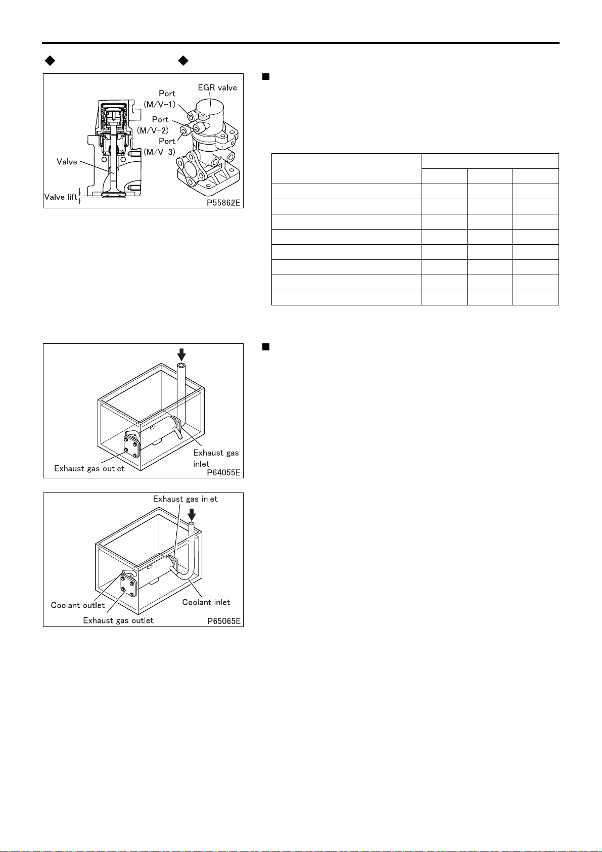
17-28
Inspection procedures
Inspection: EGR valve lift
• While applying specified air pressure to the ports in accordance
with the table below, measure the valve lift in operating steps 1
to 8 on each valve.
• Replace the EGR valve if it does not conform to the standard
value.
O: Air applied
–: Air not applied
Inspection: EGR cooler
(1) Exhaust gas passage side
• Fit a cover over the exhaust gas outlet of the EGR cooler, and
connect a hose to the exhaust gas inlet. Then, submerge the
EGR cooler in a container of water. Make sure the coolant pas-
sage is full of water.
• Apply specified air pressure through the hose. Check that air
does not leak from any part.
• If there is any leakage, replace the EGR cooler.
(2) Coolant passage side
• Fit covers over the EGR cooler’s exhaust gas inlet, exhaust gas
outlet, and coolant outlet, and connect a hose to the coolant in-
let. Then, submerge the EGR cooler in a container of water.
• Apply specified air pressure through the hose. Check that air
does not leak from any part.
• If there is any leakage, replace the EGR cooler.
Operating step
Input port
M/V-1 M/V-2 M/V-3
1 –––
2O––
3–O–
4OO–
5––O
6O–O
7–OO
8 OOO
EGR VALVE, EGR MAGNETIC VALVE, EGR PIPE AND EGR COOLER
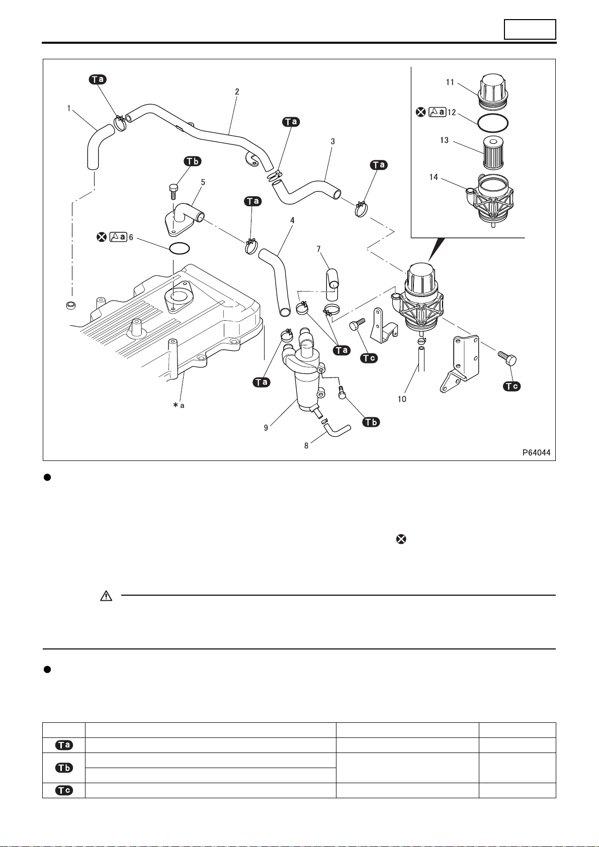
17
17-29
Removal sequence
CAUTION
• For information on the element replacement interval, refer to the element instruction manual. If the ele-
ment is used beyond its replacement interval, it may become clogged, causing the pressure inside the en-
gine to increase such that oil leakage occurs.
Installation sequence
Perform installation by following the removal sequence in reverse.
Tightening torque (Unit: N·m {kgf·m})
Mark Parts to be tightened Tightening torque Remarks
Clamp 4.0 {0.4} –
Bolt (PCV pipe mounting)
54 {5.5} –
Bolt (oil separator mounting)
Bolt (PCV valve mounting) 24 {2.4} –
1 PCV hose
2 PCV pipe
3 PCV hose
4 PCV hose
5 PCV pipe
6 O-ring
7 PCV hose
8 Oil hose
9 Oil separator
10 Oil hose
11 Cap
12 O-ring
13 Element
14 PCV body
*
a: Rocker cover
: Non-reusable parts
PCV: Positive crankcase ventilation
BLOWBY GAS RETURN SYSTEM

LAST PAGE
Lubricant and/or sealant
Mark Points of application Specified lubricant and/or sealant Quantity
O-ring Engine oil As required
BLOWBY GAS RETURN SYSTEM
Mits
ubishi 6M70 Engine Parts contact:
email: [email protected]
Phone: 269 673 1638