
Emergency Call Terminal
Quick Start Guide
V1.0.2
I
Foreword
General
This manual introduces the installation, functions and operations of the Emergency Call Terminal
device (hereinafter referred to as "the Terminal"). Read carefully before using the device, and keep the
manual safe for future reference.
Safety Instructions
The following categorized signal words with defined meaning might appear in the manual.
Signal Words Meaning
DANGER
Indicates a high potential hazard which, if not avoided, will result in
death or serious injury.
WARNING
Indicates a medium or low potential hazard which, if not avoided,
could result in slight or moderate injury.
CAUTION
Indicates a potential risk which, if not avoided, could result in
property damage, data loss, lower performance, or unpredictable
result.
TIPS
Provides methods to help you solve a problem or save you time.
NOTE
Provides additional information as the emphasis and supplement to
the text.
Revision History
Version Revision Content Release Time
V1.0.2 Revised description of words. September 2022
V1.0.1
1. Delete the image of Management
Platform in Figure1-4 Networking.
2. Change the font from Arial to Myraid pro.
3. Update the About the Manual section.
August 2021
V1.0.0 First release. April 2020
Privacy Protection Notice
As the device user or data controller, you might collect the personal data of others such as their face,
fingerprints, and license plate number. You need to be in compliance with your local privacy protection
laws and regulations to protect the legitimate rights and interests of other people by implementing
measures which include but are not limited: Providing clear and visible identification to inform people
of the existence of the surveillance area and provide required contact information.

II
About the Manual
The manual is for reference only. Slight differences might be found between the manual and the
product.
We are not liable for losses incurred due to operating the product in ways that are not in
compliance with the manual.
The manual will be updated according to the latest laws and regulations of related jurisdictions.
For detailed information, see the paper user’s manual, use our CD-ROM, scan the QR code or visit
our official website. The manual is for reference only. Slight differences might be found between
the electronic version and the paper version.
All designs and software are subject to change without prior written notice. Product updates
might result in some differences appearing between the actual product and the manual. Please
contact customer service for the latest program and supplementary documentation.
There might be errors in the print or deviations in the description of the functions, operations and
technical data. If there is any doubt or dispute, we reserve the right of final explanation.
Upgrade the reader software or try other mainstream reader software if the manual (in PDF
format) cannot be opened.
All trademarks, registered trademarks and company names in the manual are properties of their
respective owners.
Please visit our website, contact the supplier or customer service if any problems occur while
using the device.
If there is any uncertainty or controversy, we reserve the right of final explanation.
III
Important Safeguards and Warnings
This section introduces content covering the proper handling of the device, hazard prevention, and
prevention of property damage. Read carefully before using the device, and comply with the
guidelines when using it.
Operation Requirements
●
Check whether the power supply is correct before use.
●
Do not unplug the power cord on the side of the device while the adapter is powered on.
●
Operate the device within the rated range of power input and output.
●
Transport, use and store the device under allowed humidity and temperature conditions.
●
Do not drop or splash liquid onto the device, and make sure that there is no object filled with liquid
on the device to prevent liquid from flowing into it.
●
Do not disassemble the device without professional instruction.
Installation Requirements
●
Do not connect the power adapter to the device while the adapter is powered on.
●
Strictly comply with the local electric safety code and standards. Make sure the ambient voltage is
stable and meets the power supply requirements of the device.
●
Do not connect the device to two or more kinds of power supplies, to avoid damage to the device.
●
Improper use of the battery might result in a fire or explosion.
●
Personnel working at heights must take all necessary measures to ensure personal safety including
wearing a helmet and safety belts.
●
Do not place the device in a place exposed to sunlight or near heat sources.
●
Keep the device away from dampness, dust, and soot.
●
Install the device on a stable surface to prevent it from falling.
●
Install the device in a well-ventilated place, and do not block its ventilation.
●
Use an adapter or cabinet power supply provided by the manufacturer.
●
Use the power cords that are recommended for the region and conform to the rated power
specifications.
●
The power supply must conform to the requirements of ES1 in IEC 62368-1 standard and be no
higher than PS2. Please note that the power supply requirements are subject to the device label.
●
The device is a class I electrical appliance. Make sure that the power supply of the device is
connected to a power socket with protective earthing.

1
Table of Contents
Foreword ............................................................................................................................................................ I
Important Safeguards and Warnings ............................................................................................................. III
1 Product Overview .......................................................................................................................................... 2
Introduction ................................................................................................................................................................................. 2
Structure ........................................................................................................................................................................................ 2
1.2.1 Front Panel ...................................................................................................................................................................... 2
1.2.2 Rear Panel ........................................................................................................................................................................ 3
1.2.3 Device Ports .................................................................................................................................................................... 4
Typical Networking .................................................................................................................................................................... 5
2 Installation ..................................................................................................................................................... 6
Screws............................................................................................................................................................................................. 6
Mounting Plate Dimensions .................................................................................................................................................. 6
Procedure ...................................................................................................................................................................................... 7
3 Web Operations ............................................................................................................................................. 9
Initialization .................................................................................................................................................................................. 9
Login ............................................................................................................................................................................................. 10
Password Reset ......................................................................................................................................................................... 10
Local Settings ............................................................................................................................................................................ 11
3.4.1 Basic Settings................................................................................................................................................................ 11
3.4.2 Video & Audio ............................................................................................................................................................... 12
3.4.3 System Settings ........................................................................................................................................................... 14
3.4.4 Alarm Output Settings .............................................................................................................................................. 15
3.4.5 Security Management ............................................................................................................................................... 15
3.4.6 Onvif User ...................................................................................................................................................................... 16
Network Settings ...................................................................................................................................................................... 17
3.5.1 TCP/IP .............................................................................................................................................................................. 17
3.5.2 Firewall ............................................................................................................................................................................ 18
3.5.3 Register ........................................................................................................................................................................... 19
Logout .......................................................................................................................................................................................... 20
Restart .......................................................................................................................................................................................... 20
Restoring to Factory Settings .............................................................................................................................................. 20
4 Basic Functions ............................................................................................................................................ 21
Calling ........................................................................................................................................................................................... 21
Monitoring and Listening ..................................................................................................................................................... 21
Light Compensation ............................................................................................................................................................... 21
Tampering Alarm ...................................................................................................................................................................... 21
Alarm Linkage ........................................................................................................................................................................... 21
5 FAQ ............................................................................................................................................................... 22
Cybersecurity Recommendations ............................................................................................. 23
2
1 Product Overview
Introduction
The Terminal can be connected with the management platform and master station (VTS) to provide
emergency calling, voice broadcasting, video monitoring, and more. It is applicable to schools, banks,
industrial parks, apartments, office buildings and other places. And it can be configured on the web
page.
Structure
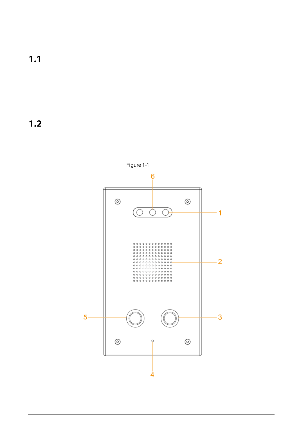
1.2.1 Front Panel
Front panel
3
Table 1-1 Front panel description
No. Name Description
1 Illuminator
When the light is insufficient and the Terminal is monitored or
calling, the illuminator is turned on automatically.
2 Speaker Outputs audio.
3 Service button Calls the management center.
4 Microphone Inputs audio.
5 SOS button Sends alarms to the management center.
6 Camera Capture videos.
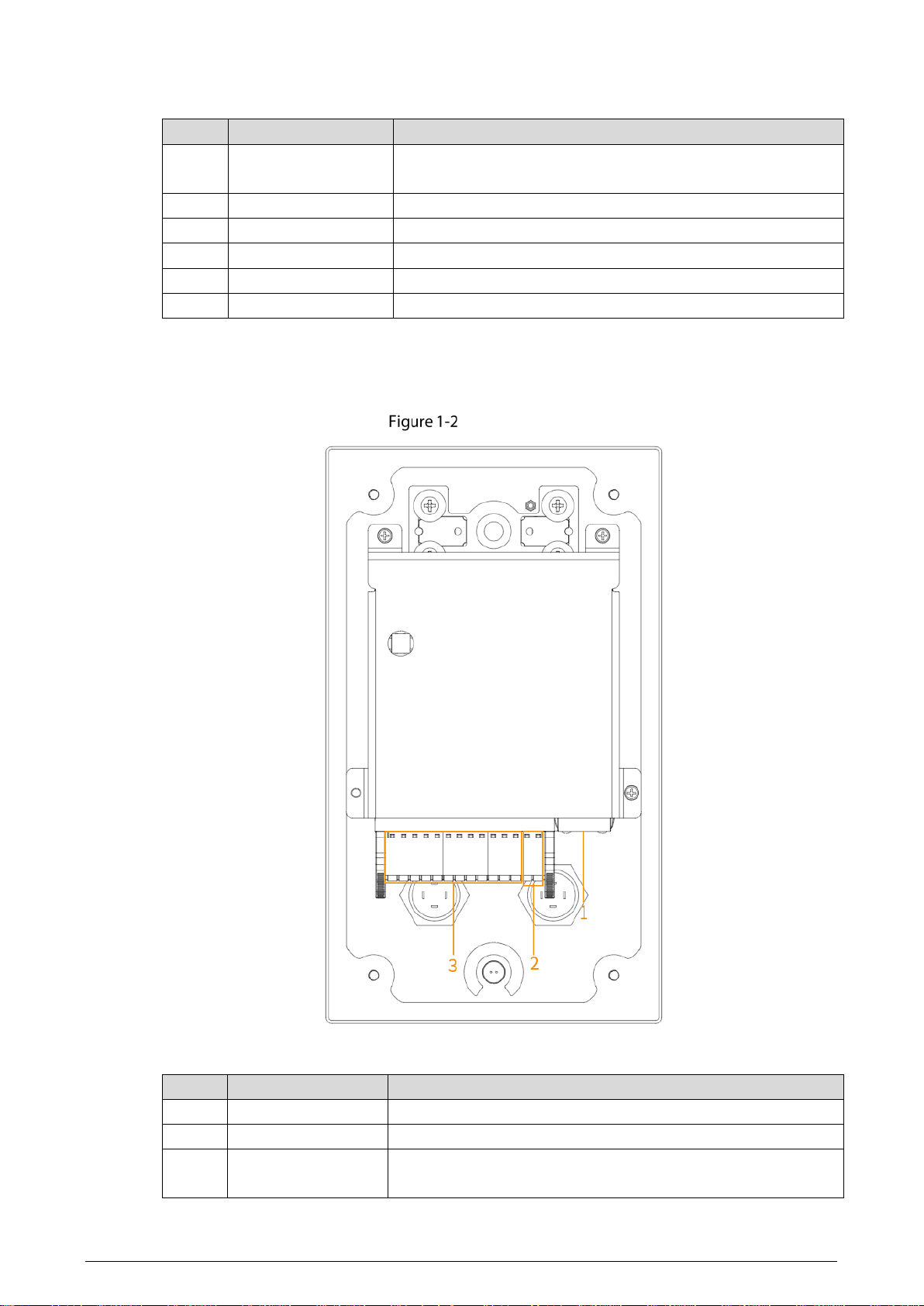
1.2.2 Rear Panel
Rear panel
Table 1-2 Rear panel description
No. Name Description
1 Network port Insert network cable (RJ-45 connector).
2 Power port Connect 12 VDC power supply.
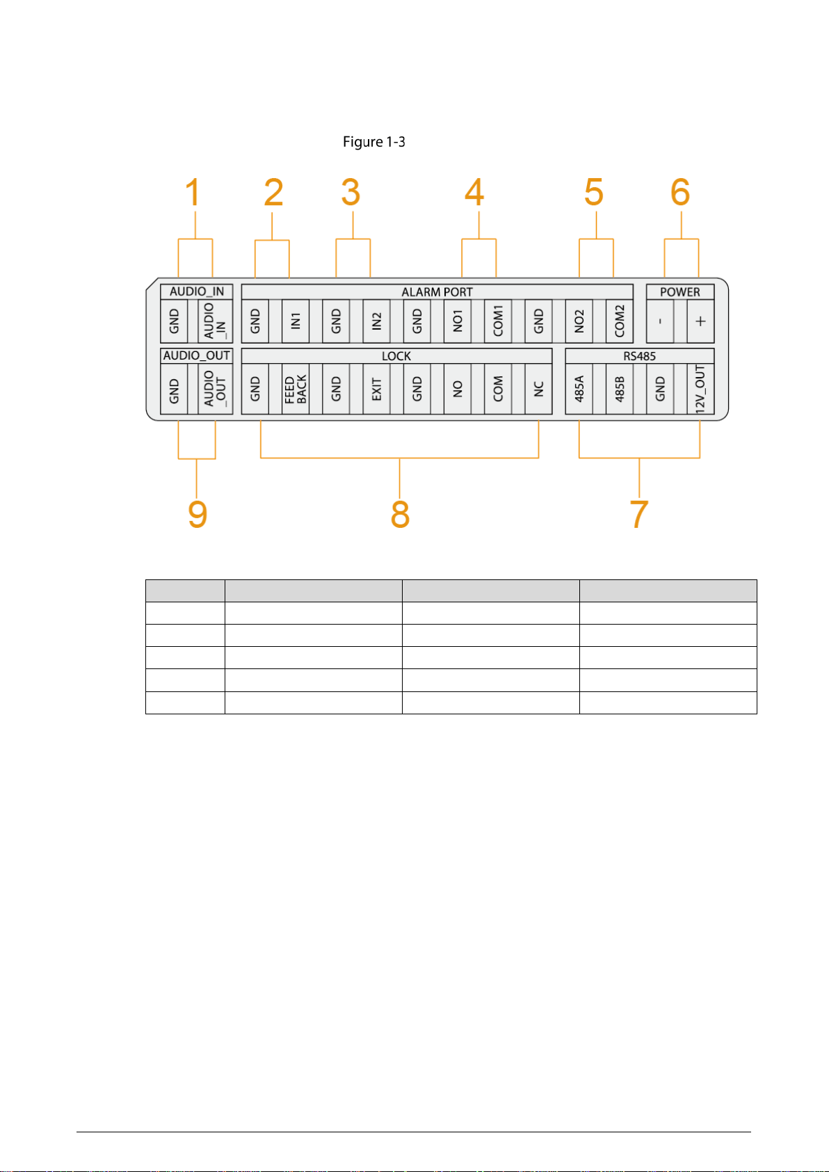
3 Device ports
For audio input and output, alarm input and output, RS-485, and
so on. For details, see "1.2.3 Device Ports."
4
1.2.3 Device Ports
Device ports
Table 1-3 Device ports description
No. Name No. Name
1 MIC 6 Power input
2 Alarm input 1 7 RS-485
3 Alarm input 2 8 Reserved ports
4 Alarm output 1 9 Active speaker
5 Alarm output 2 — —
5
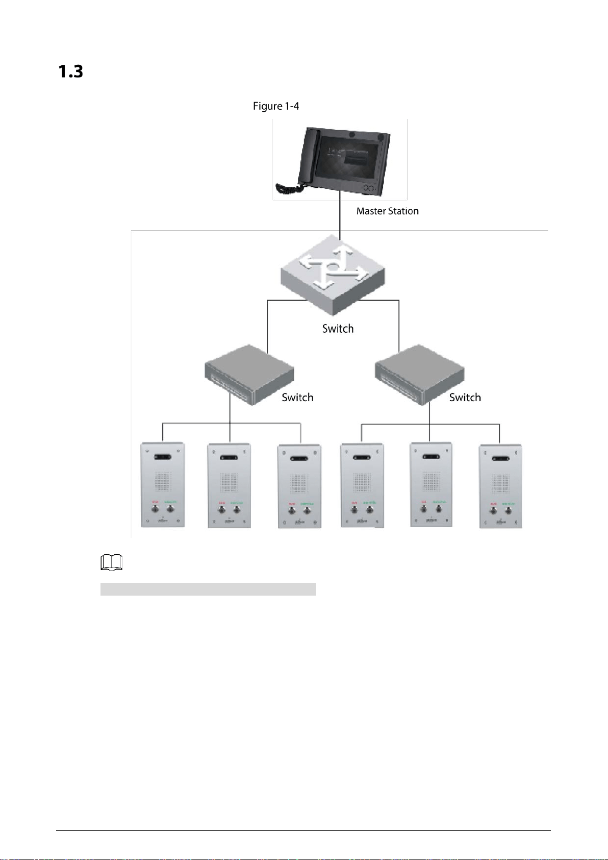
Typical Networking
Networking
The master station in the networking is optional.
6
2 Installation
Do not install the Terminal in places with condensation, high temperature, grease, dust, chemical
corrosion, or direct sunlight.
In case of abnormality after powering on, cut off the power supply immediately, and then pull out
the network cable. Power on again after troubleshooting.
Engineering installation and debugging shall be done by professional teams. Do not dismantle
or repair arbitrarily in case of device failure. Contact after-sales department.
Surface mount is supported, and rear cable outlet and bottom cable outlet are reserved on the
mounting plate.
Screws
Before installing the Terminal, check the screws in the accessory package.
Table 2-1 Screws
Name Figure Quantity
M3 × 8 hexalobular socket screw
4
ST3 × 18 self-tapping screw
4
Expansion bolt
4
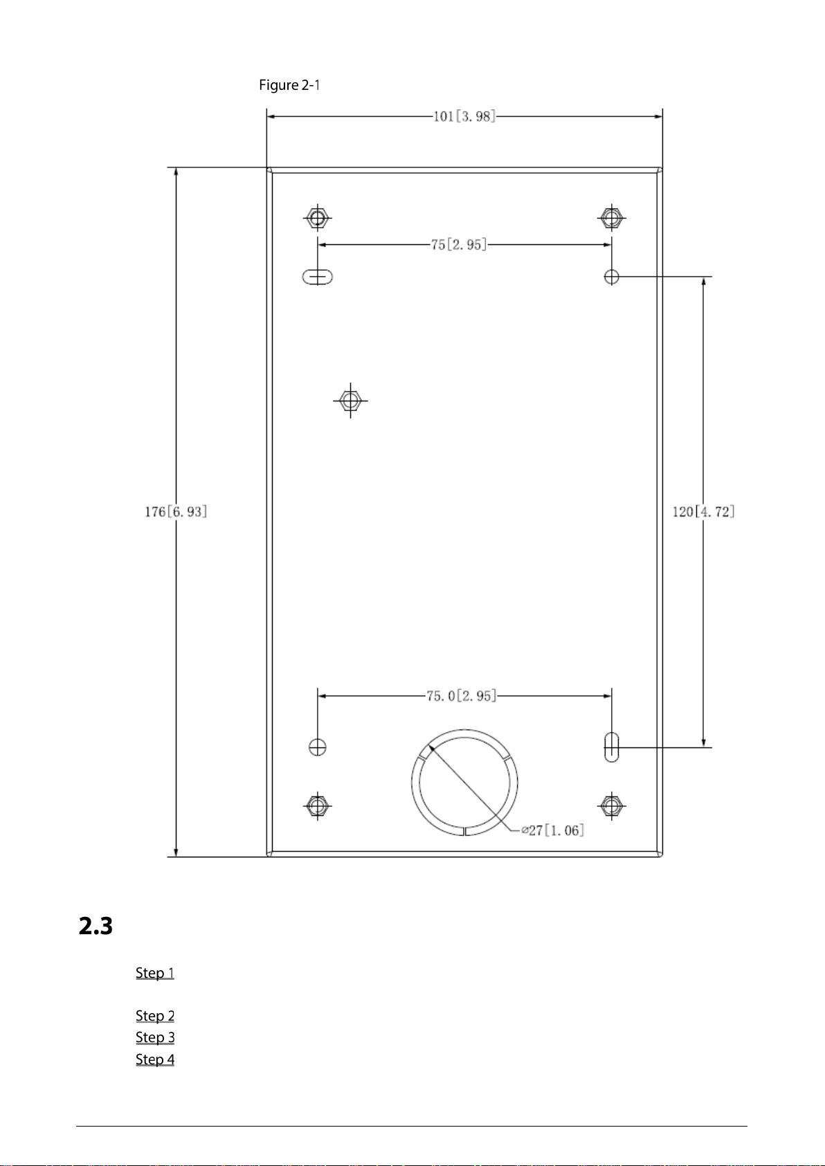
Mounting Plate Dimensions
Before installing the Terminal, see the mounting plate dimensions first to provide enough installation
space.
7
Mounting plate dimensions (mm [inch])
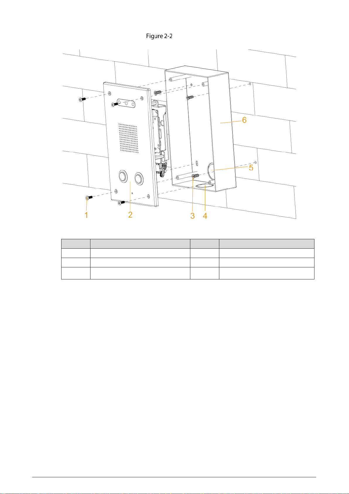
Procedure
Drill 4 holes on the wall according to the screw holes on the mounting plate, and put the
expansion bolts into the holes.
Fix the mounting plate on the wall with the ST3×18 self-tapping screws.
Apply sealant between the mounting plate and the wall, and to cover the cable outlets.
Fix the Terminal to the mounting plate with M3X8 hexalobular socket screws.
8
Installation
Table 2-2 Installation component
No. Name No. Name
1 M3X8 hexalobular socket screw 4 Bottom cable outlet
2 Emergency Call Terminal 5 Rear cable outlet
3 ST3×18 self-tapping screw 6 Mounting plate
9
3 Web Operations
Initialization
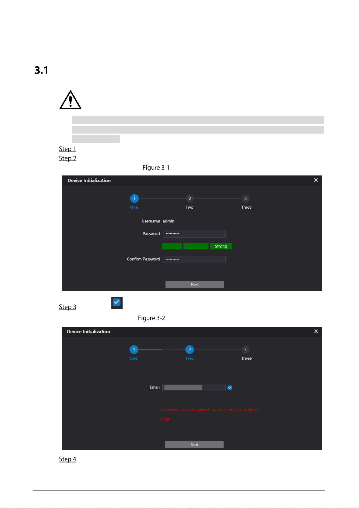
For first-time login, or login after restoring to factory settings, you need to initialize the Terminal.
The IP address is 192.168.1.108 by default. Make sure that the PC and the Terminal are in the same
network segment.
Enter the IP address of the Terminal in the address bar.
Enter and confirm the password according to the on-screen prompts, and then click Next.
Password setting
Select the checkbox, enter the email address, and then click Next.
Password protection
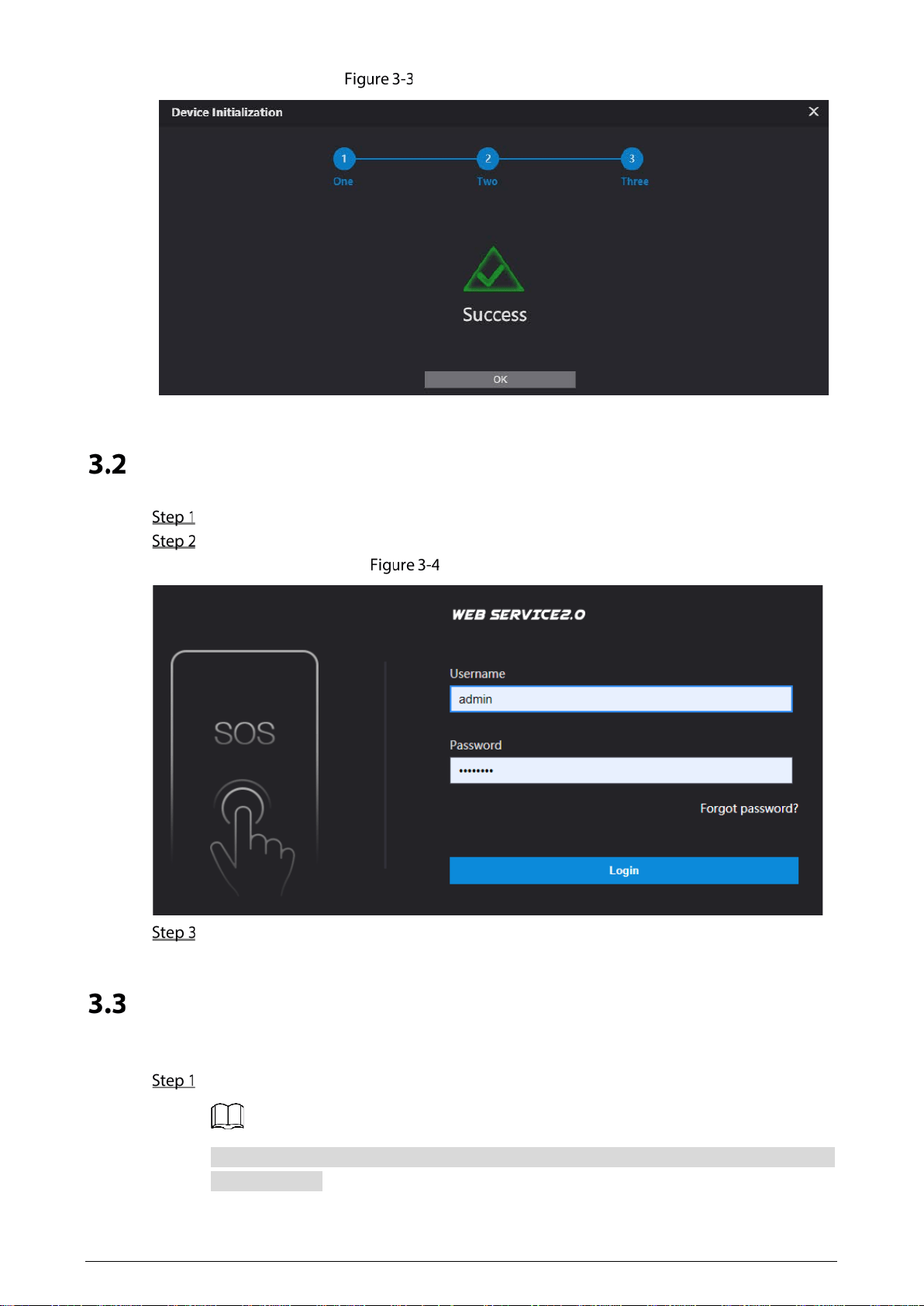
Click OK.
10
Initialization completed
Login
Enter the IP address of the Terminal in the address bar.
Enter the username and password.
Login web page
Click Login.
Password Reset
If you forget the password when logging in to the web page, you can reset the password.
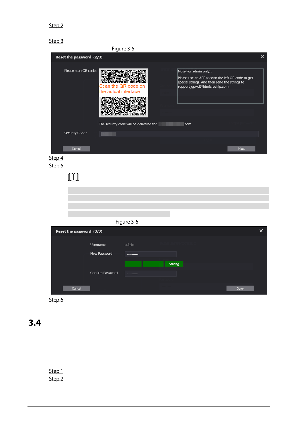
Click Forgot password? on the login web page.
If you use IE browser, the system might prompt Stop running the script, click No to continue
to run the script.
11
Click Next, scan the QR code according to the on-screen prompts, and you will get the security
code.
In the Security Code box, enter the security code received in your provided mailbox.
Enter the security code
Click Next.
Enter and confirm the new password.
The password should consist of 8 to 32 non-blank characters and contain at least two types
of characters among uppercase, lowercase, number, and special character (excluding ' " ; : &).
The confirming password should be the same as the new password. Set a strong password
according to the prompt of password strength.
Resetting password
Click Save.
Local Settings
3.4.1 Basic Settings
Set the name of the Terminal for easy identification.
Select Local Setting > Basic on the web page.
Enter the device name.
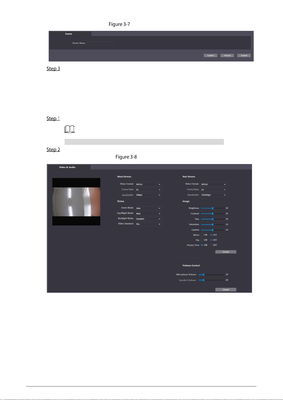
12
Device name setting
Click Confirm.
3.4.2 Video & Audio
You can set the brightness, contrast, hue, saturation and scene mode of the monitoring screen, and
adjust the volume of the Terminal.
Select Local Setting > Video & Audio on the web page.
If the plug-in has not been installed, follow on-screen instructions to install it.
Configure parameters.
Video & audio

13
Table 3-1 Video & audio parameter description
Parameter Description
Video Format
The Terminal supports 720P (1280 × 720), WVGA (800 × 480), D1 (720
× 576), and CIF (352 × 288). You can select as needed.
Frame Rate
The number of frames per second in a video. The higher the frame rate
is, the more clear and smooth the video will be.
Bandwidth
Select the bandwidth according to the network the Terminal is
connected to.
Brightness
The overall brightness of the image.
The larger the value is, the brighter the image will become.
The image might be white if the value is too large.
Contrast
The ratio of black to white in the image. The larger the value is, the
richer the image color.
If the value is too large, the dark area becomes darker and the
bright area is likely to be overexposed.
The image might be greyish if the value is too small.
Hue
Adjust the color of the image. The larger the value, the darker the
color.
Saturation
Adjust the image vividness. The larger the value, the more vivid the
image. This value does not affect the overall brightness of image.
Gamma Change the image brightness and contrast in a non-linear way. The
larger the value, the brighter the image.
Mirror Flip the image horizontally.
Flip Flip the image vertically.
Display Time Display the time at the top left corner of the monitoring screen.
Scene Mode
The overall tone of the image varies with the scene modes.
Disabled: No mode is set.
Auto: Automatically adjust the scene mode to make the image
color normal according to the light reaching the sensor. This mode
is selected by default.
Sunny: The image tone is decreased in this mode.
Night: The image tone is increased in this mode.
Day/Night Mode
This mode affects the illumination of the Terminal.
Auto: Automatically adjust the mode to make the image color
normal according to the light reaching the sensor.
Color: The image is colored.
B/W: The image is black and white.
Backlight Mode
Select the appropriate compensation mode according to the actual
conditions.
When human faces are in the backlight, it is recommended to select
WDR.
Disabled: No compensation is made.
14
Parameter Description
BLC: Backlight compensation corrects areas with extremely high
or low levels of light to maintain a normal and usable level of light
for the object in focus.
WDR: The system dims bright areas and compensates dark areas
to ensure the clarity of all areas
according to the lighting
conditions.
HLC: The system constrains bright areas and reduces halo size to
dim the overall brightness.
Video Standard
Select PAL or NTSC as needed.
PAL: The frame rate is 25 fps by default.
NTSC: The frame rate is 30 fps by default.
Microphone
Volume/Speaker Volume
Adjusts the volume of the microphone or speaker.
3.4.3 System Settings
You can set the time zone, system time, DST type and NTP timing.
Select Local Setting > System on the web page.
Configure parameters.
System settings
Table 3-2 System settings parameters
Parameter Description
Date Format
Select the display format of the date from YYYY-MM-DD, MM-DD-YYYY
and DD-MM-YYYY.
Time Format
Select the time format from 24-Hour and 12-Hour.
Time Zone Select the local time zone.
System Time
Set the system time manually.
Click Sync PC to synchronize the system time with the PC time.
DST setting
Select the ON checkbox to enable DST.
1. Select Date or Week as the DST Type.
2.
Set the Start Time and End Time.
15
Parameter Description
NTP setting
Set NTP time synchronization.
1. Select the NTP Enable checkbox.
2. Configure parameters.
NTP Server: Enter the IP address of the time server for the Terminal to
synchronize time.
Port: Enter the port number of the time server.
Interval: Enter the interval at which the time is synchronized.
Maintenance Set the auto maintenance time of the system.
SSH
You can enable SSH (Secure Shell) authentication to perform safety
management. The function is disabled by default.
Click Save.
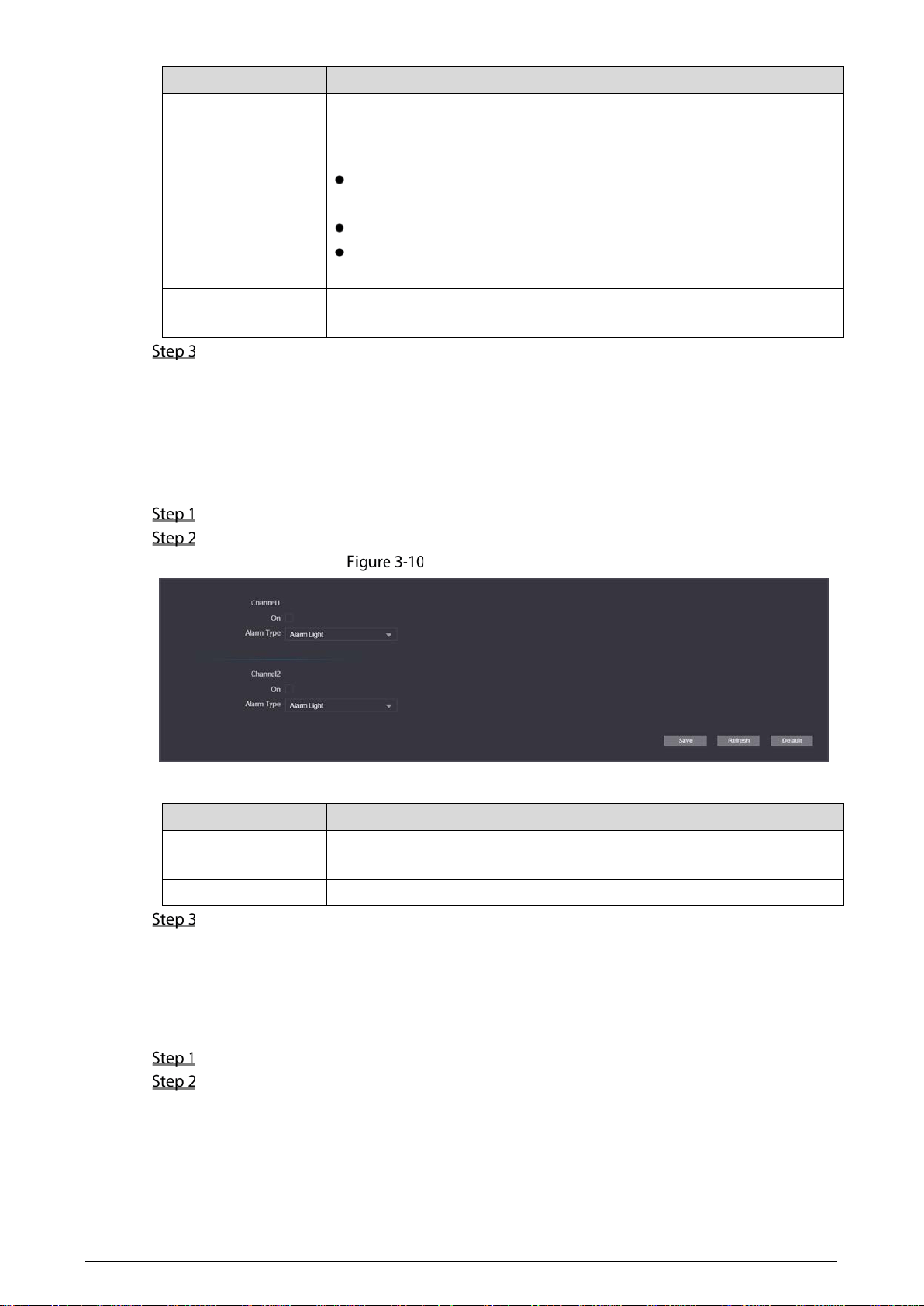
3.4.4 Alarm Output Settings
After the alarm output is enabled, when the Terminal initiates a call, the alarm output relay can output
the alarm signal.
Select Local Setting > Alarm Output on the web page.
Configure parameters.
Alarm output settings
Table 3-3 System settings parameters
Parameter Description
Channel
The Terminal has two alarm outputs. Select the alarm output channel
according to the alarm device you have installed.
Alarm Type
Alarm Light is selected by default.
Click Save.
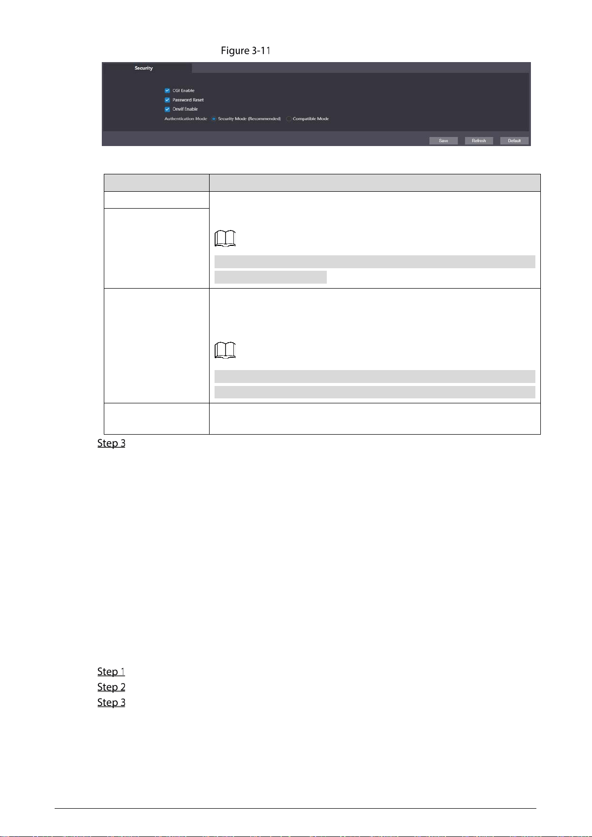
3.4.5 Security Management
You can configure system service to ensure secure management.
Select Local Setting > Security on the web page.
Configure parameters.
16
Security management
Table 3-4 Security management parameter description
Parameter Description
CGI Enable
Enabled by default. The Terminal can connect with other network video
products through this protocol.
CGI (Common
Gateway Interface) is an interface between external
programs and web server.
Onvif Enable
Password Reset
Enabled by default to allow password resetting and setting reserved email
address. After successful setting, you can reset the password by clicking
Forgot password? on the login web page.
If the function is disabled, you can only reset the password after restoring
the Terminal to factory settings by pressing the reset button on the device.
Authentication Mode
Select the anthentication mode from Security Mode and Compatible
Mode.
Click Save.
3.4.6 Onvif User
The function is mainly for acquiring streams through Onvif protocol, and the information of the Onvif
user needs to be validated. You can add or delete Onvif users, and modify their passwords. The Onvif
user is admin by default.
Preparation
On the web page, select Local Setting > Security, and then select the Onvif Enable checkbox.
Procedure
Select Local Setting > Onvif User on the web page.
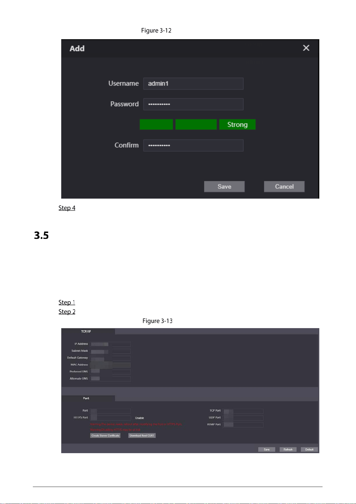
Click Add.
Enter the username and password, and then confirm the password you entered.
17
Add Onvif users
Click Save.
Network Settings
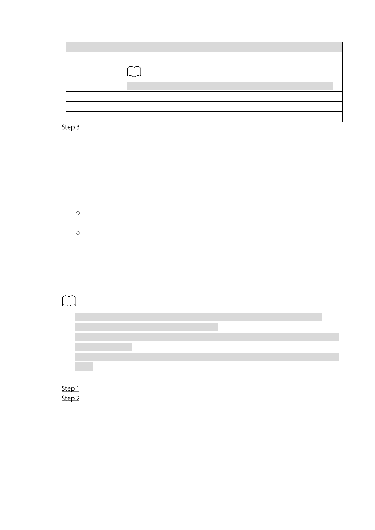
3.5.1 TCP/IP
You can configure the IP address and DNS server to connect the Terminal to other devices in the
network.
Select Network > Basic on the web page.
Configure parameters.
TCP/IP settings
18
Table 3-5 TCP/IP parameter description
Parameter Description
IP Address Enter the IP address, subnet mask, and default gateway you planned.
The IP address and default gateway must be in the same network segment.
Subnet Mask
Default Gateway
MAC Address The MAC (Media Access Control) address of the Terminal.
Preferred DNS The IP address of the DNS server.
Alternate DNS Alternate IP address of the DNS server.
Click Save.
3.5.2 Firewall
You can configure network access, PING prohibited, and anti-half connection to strengthen the
security of the network and data.
Network Access: Restrict access by setting block list and allow list.
Allow List: Only if the IP or MAC address of the user is in the allow list, can the Terminal be
accessed. If a port is also set, the user can only access the specified port.
Block List: If the IP or MAC address of the user is in the block list, the Terminal cannot be
accessed. If a port is also set, the user cannot access the specified port.
PING Prohibited: If the function is enabled, the Terminal will not respond ping request.
Anti-Half Connection: If the function is enabled, the Terminal can provide services normally
when there is half connection attack.
You cannot add the IP address or MAC address of the Terminal to the allow list or block list.
When adding MAC address, you cannot set the port.
MAC address verification takes effect only when the IP address of the Terminal and PC of the user
are in the same LAN.
When the Terminal is accessed through WAN, the system can only verify the MAC address of the
router.
This section takes setting network access as an example.
Select Network > Firewall on the web page.
Select Network Access as the Type, and then select the Enable checkbox.
When enabling PING Prohibited and Anti Half Connection, you do not need to set
parameters. Click Confirm to complete the settings.
When enabling Network Access, you need to configure allow list or block list. Here are
the steps.
1. Select Allow List or Block List as the Mode.
2. Click Add.
3. Configure parameters.
19
Table 3-6 Firewall parameters description
Parameter Description
Type
Select IP Address, IP Segment, MAC Address or All IP Addresses.
IP Address: Select the IP version, and then enter the IP address to be
added.
IP Segment
: Select the IP version, and then enter the Initial IPv4
Address, and End IPv4 Address.
MAC Address: Enter the MAC address to be added.
All IP Addresses: Set all IP addresses to the allow list or block list.
All Device Ports
Set access ports. You can select all device ports, or set the port range.
All Device Ports: Set all ports of the Terminal to the block list or allow
list. When all IP addresses are set to the block list, you are not allowed
to select all ports. Because in this case, all devices cannot access all ports
of the Terminal.
Device Start Sever Port/Device End Sever Port: Set the start port and
end port. The value ranges from 1 to 65535.
Device Start Sever
Port
Device End Sever
Port
4. Click Save.
The system goes back to the Firewall web page.
Click Confirm.
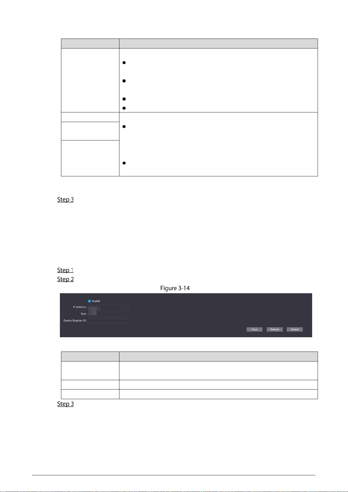
3.5.3 Register
The Terminal registers to the proxy server designated by the user, and then the proxy server provides
the transfer function to facilitate the client software to access the Terminal, so as to watch live view
and monitor the scene.
Select Network > Register on the web page.
Select the Enable checkbox, and then set parameters.
Register
Table 3-7 Register parameter description
Parameter Description
IP Address
The IP address or domain name of the server that the Terminal is registered
to.
Port The sever port for registering.
Device Register ID Customize the register ID for the Terminal.
Click Save.
20
Logout
Click , and then select Exit to log out.
Restart
Click , and then select Reboot to restart the Terminal.
Restoring to Factory Settings
Click , and then select Factory Defaults to restore the Terminal to factory settings.
The operation will clear the data of the Terminal. Be cautious.

21
4 Basic Functions
Calling
If you have connected the Terminal to the entrance and exit management platform or master station,
you can press the SOS or service button on the Terminal to call the platform client and master station.
For details of adding the Terminal to the platform or master station, see the platform user's manual or
the master station user's manual.
Monitoring and Listening
The management center can initialize monitoring or listening on the Terminal to remotely see the
monitoring screen of the Terminal, and listen to the audio.
Light Compensation
When the ambient light is dim or at night, the Terminal can compensate the light automatically with
the photosensitive technology to ensure a clearer image.
Tampering Alarm
The Terminal has a built-in tampering alarm switch. When the Terminal is removed from the wall, an
alarm is triggered and sent to the management center.
Alarm Linkage
Alarm input, alarm output and other linkage functions can be customized according to customer
requirements.

22
5 FAQ
Table 5-1 FAQ
Problem Solution
The Terminal has no
sound or light, and
cannot be powered
on.
Check whether the power supply is normal and the socket is in good
contact.
There is a prompt
that the call is not
successful.
Network failure. Check whether the network cable is properly connected.
The user has some
uncertainties or
cannot solve the
problems.
Contact the technical support personnel.

23
Cybersecurity Recommendations
Mandatory actions to be taken for basic device network security:
1. Use Strong Passwords
Please refer to the following suggestions to set passwords:
The length should not be less than 8 characters.
Include at least two types of characters; character types include upper and lower case
letters, numbers and symbols.
Do not contain the account name or the account name in reverse order.
Do not use continuous characters, such as 123, abc, etc.
Do not use overlapped characters, such as 111, aaa, etc.
2. Update Firmware and Client Software in Time
According to the standard procedure in Tech-industry, we recommend to keep your device
(such as NVR, DVR, IP camera, etc.) firmware up-to-date to ensure the system is equipped
with the latest security patches and fixes. When the device is connected to the public
network, it is recommended to enable the “auto-check for updates” function to obtain
timely information of firmware updates released by the manufacturer.
We suggest that you download and use the latest version of client software.
"Nice to have" recommendations to improve your device network security:
1. Physical Protection
We suggest that you perform physical protection to device, especially storage devices. For
example, place the device in a special computer room and cabinet, and implement well-done
access control permission and key management to prevent unauthorized personnel from
carrying out physical contacts such as damaging hardware, unauthorized connection of
removable device (such as USB flash disk, serial port), etc.
2. Change Passwords Regularly
We suggest that you change passwords regularly to reduce the risk of being guessed or cracked.
3. Set and Update Passwords Reset Information Timely
The device supports password reset function. Please set up related information for password
reset in time, including the end user’s mailbox and password protection questions. If the
information changes, please modify it in time. When setting password protection questions, it is
suggested not to use those that can be easily guessed.
4. Enable Account Lock
The account lock feature is enabled by default, and we recommend you to keep it on to guarantee
the account security. If an attacker attempts to log in with the wrong password several times, the
corresponding account and the source IP address will be locked.
5. Change Default HTTP and Other Service Ports
We suggest you to change default HTTP and other service ports into any set of numbers between
1024–65535, reducing the risk of outsiders being able to guess which ports you are using.
6. Enable HTTPS
We suggest you to enable HTTPS, so that you visit Web service through a secure communication
channel.
7. MAC Address Binding
We recommend you to bind the IP and MAC address of the gateway to the device, thus reducing

24
the risk of ARP spoofing.
8. Assign Accounts and Privileges Reasonably
According to business and management requirements, reasonably add users and assign a
minimum set of permissions to them.
9. Disable Unnecessary Services and Choose Secure Modes
If not needed, it is recommended to turn off some services such as SNMP, SMTP, UPnP, etc., to
reduce risks.
If necessary, it is highly recommended that you use safe modes, including but not limited to the
following services:
SNMP: Choose SNMP v3, and set up strong encryption passwords and authentication
passwords.
SMTP: Choose TLS to access mailbox server.
FTP: Choose SFTP, and set up strong passwords.
AP hotspot: Choose WPA2-PSK encryption mode, and set up strong passwords.
10. Audio and Video Encrypted Transmission
If your audio and video data contents are very important or sensitive, we recommend that you
use encrypted transmission function, to reduce the risk of audio and video data being stolen
during transmission.
Reminder: encrypted transmission will cause some loss in transmission efficiency.
11. Secure Auditing
Check online users: we suggest that you check online users regularly to see if the device is
logged in without authorization.
Check device log: By viewing the logs, you can know the IP addresses that were used to log
in to your devices and their key operations.
12. Network Log
Due to the limited storage capacity of the device, the stored log is limited. If you need to save the
log for a long time, it is recommended that you enable the network log function to ensure that
the critical logs are synchronized to the network log server for tracing.
13. Construct a Safe Network Environment
In order to better ensure the safety of device and reduce potential cyber risks, we recommend:
Disable the port mapping function of the router to avoid direct access to the intranet devices
from external network.
The network should be partitioned and isolated according to the actual network needs. If
there are no communication requirements between two sub networks, it is suggested to use
VLAN, network GAP and other technologies to partition the network, so as to achieve the
network isolation effect.
Establish the 802.1x access authentication system to reduce the risk of unauthorized access
to private networks.
Enable IP/MAC address filtering function to limit the range of hosts allowed to access the
device.
