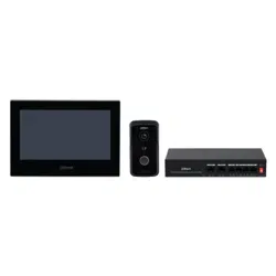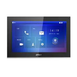

2-Wire Hybrid Indoor Monitor
User's Manual
V1.0.0
I
Foreword
General
This manual introduces the structure, functions, and operations of the 2-wire hybrid indoor monitor
(hereinafter referred to as "the VTH"). Read carefully before using the device, and keep the manual
safe for future reference.
Safety Instructions
The following signal words might appear in the manual.
Signal Words Meaning
Indicates a high potential hazard which, if not avoided, will result in
death or serious injury.
Indicates a medium or low potential hazard which, if not avoided,
could result in slight or moderate injury.
Indicates a potential risk which, if not avoided, could result in
property damage, data loss, reductions in performance, or
unpredictable results.
Provides methods to help you solve a problem or save time.
Provides additional information as a supplement to the text.
Revision History
Version Revision Content Release Time
V1.0.0 First Release. August 2023
Privacy Protection Notice
As the device user or data controller, you might collect the personal data of others such as their face,
fingerprints, and license plate number. You need to be in compliance with your local privacy
protection laws and regulations to protect the legitimate rights and interests of other people by
implementing measures which include but are not limited: Providing clear and visible identification
to inform people of the existence of the surveillance area and provide required contact information.
About the Manual
●
The manual is for reference only. Slight differences might be found between the manual and the
product.
●
We are not liable for losses incurred due to operating the product in ways that are not in
compliance with the manual.
●
The manual will be updated according to the latest laws and regulations of related jurisdictions.
For detailed information, see the paper user’s manual, use our CD-ROM, scan the QR code or visit
our official website. The manual is for reference only. Slight differences might be found between
the electronic version and the paper version.
●
All designs and software are subject to change without prior written notice. Product updates

II
might result in some differences appearing between the actual product and the manual. Please
contact customer service for the latest program and supplementary documentation.
●
There might be errors in the print or deviations in the description of the functions, operations
and technical data. If there is any doubt or dispute, we reserve the right of final explanation.
●
Upgrade the reader software or try other mainstream reader software if the manual (in PDF
format) cannot be opened.
●
All trademarks, registered trademarks and company names in the manual are properties of their
respective owners.
●
Please visit our website, contact the supplier or customer service if any problems occur while
using the device.
●
If there is any uncertainty or controversy, we reserve the right of final explanation.
III
Important Safeguards and Warnings
This section introduces content covering the proper handling of the device, hazard prevention, and
prevention of property damage. Read carefully before using the device, and comply with the
guidelines when using it.
Operation Requirements
●
Check whether the power supply is correct before use.
●
Do not unplug the power cord on the side of the device while the adapter is powered on.
●
Operate the device within the rated range of power input and output.
●
Transport, use and store the device under allowed humidity and temperature conditions.
●
Do not drop or splash liquid onto the device, and make sure that there is no object filled with
liquid on the device to prevent liquid from flowing into it.
●
Do not disassemble the device without professional instruction.
Installation Requirements
●
Do not connect the power adapter to the device while the adapter is powered on.
●
Strictly comply with the local electric safety code and standards. Make sure the ambient voltage
is stable and meets the power supply requirements of the device.
●
Do not connect the device to two or more kinds of power supplies, to avoid damage to the
device.
●
Improper use of the battery might result in a fire or explosion.
●
Personnel working at heights must take all necessary measures to ensure personal safety
including wearing a helmet and safety belts.
●
Do not place the device in a place exposed to sunlight or near heat sources.
●
Keep the device away from dampness, dust, and soot.
●
Install the device on a stable surface to prevent it from falling.
●
Install the device in a well-ventilated place, and do not block its ventilation.
●
Use an adapter or cabinet power supply provided by the manufacturer.
●
Use the power cords that are recommended for the region and conform to the rated power
specifications.
●
The power supply must conform to the requirements of ES1 in IEC 62368-1 standard and be no
higher than PS2. Please note that the power supply requirements are subject to the device label.
●
The device is a class I electrical appliance. Make sure that the power supply of the device is
connected to a power socket with protective earthing.

IV
Table of Contents
Foreword
........................................................................................................................................................................................................I
Important Safeguards and Warnings
............................................................................................................................................ III
1 Production Overview
.......................................................................................................................................................................... 1
1.1 Introduction
................................................................................................................................................................................. 1
1.2 Function
......................................................................................................................................................................................... 1
2 Network Diagram
................................................................................................................................................................................. 3
3 Structure
................................................................................................................................................................................................. 10
3.1 Front Panel
.................................................................................................................................................................................. 10
3.2 Rear Panel
.................................................................................................................................................................................... 12
4 Installation and Wiring
.................................................................................................................................................................... 17
5 DIP Configuration
............................................................................................................................................................................... 19
5.1 DIP Switch Basic Mapping Rule
........................................................................................................................................ 19
5.2 DIP Switch Coding Rules
...................................................................................................................................................... 20
6 VTH Operations
................................................................................................................................................................................... 22
6.1 Home Screen
.............................................................................................................................................................................. 22
6.2 Call
................................................................................................................................................................................................... 23
6.2.1 Call Logs
............................................................................................................................................................................ 24
6.2.2 VTH Calling DMSS
......................................................................................................................................................... 26
6.3 Information
................................................................................................................................................................................. 27
6.3.1 Alarm information
........................................................................................................................................................ 27
6.3.2 Guest Message
............................................................................................................................................................... 27
6.3.3 Video Pictures
................................................................................................................................................................. 28
6.4 Monitoring
.................................................................................................................................................................................. 29
6.4.1 Monitoring VTO
............................................................................................................................................................. 29
6.4.2 Monitoring Camera
...................................................................................................................................................... 31
6.5 Setting
........................................................................................................................................................................................... 32
6.5.1 Ring Settings
................................................................................................................................................................... 32
6.5.1.1 VTO Ring
................................................................................................................................................................. 32
6.5.1.2 Alarm Ring
............................................................................................................................................................. 33
6.5.1.3 Other Ring
............................................................................................................................................................. 34
6.5.2 Alarm Setting
.................................................................................................................................................................. 34
6.5.2.1 Wired Zone
............................................................................................................................................................ 34
6.5.2.2 Alarm Output
....................................................................................................................................................... 36
6.5.3 Arm Mode Setting
........................................................................................................................................................ 37
6.5.4 General Setting
.............................................................................................................................................................. 38

V
6.5.4.1 Time and DND
...................................................................................................................................................... 38
6.5.4.2 Display
..................................................................................................................................................................... 39
6.5.4.3 Other
........................................................................................................................................................................ 40
6.5.5 WLAN
.................................................................................................................................................................................. 42
6.5.5.1 WLAN Configuration
........................................................................................................................................ 42
6.5.5.2 Wireless IP
............................................................................................................................................................. 43
6.5.6 Password Management
............................................................................................................................................. 43
6.5.6.1 User Password
..................................................................................................................................................... 43
6.5.6.2 Network Password
............................................................................................................................................ 44
6.5.6.2.1 Creating Network Password
.............................................................................................................. 44
6.5.6.2.2 Modifying Network Password
.......................................................................................................... 46
6.5.6.2.3 Resetting Network Password
............................................................................................................ 47
6.5.7 QR Code
............................................................................................................................................................................. 47
6.5.8 Product Information
.................................................................................................................................................... 48
6.5.9 Upgrading the Program
............................................................................................................................................ 48
6.6 Arming and Disarming
.......................................................................................................................................................... 49
6.6.1 Arming
................................................................................................................................................................................ 49
6.6.2 Disarming
......................................................................................................................................................................... 50
7 DMSS App
............................................................................................................................................................................................... 52
7.1 Downloading DMSS App
...................................................................................................................................................... 52
7.2 Registration and Login
......................................................................................................................................................... 52
7.3 Adding VTH to DMSS
............................................................................................................................................................. 53
7.4 Configuring Arm and Disarm
............................................................................................................................................. 58
7.5 DMSS Monitoring VTO
.......................................................................................................................................................... 59
7.6 DMSS Calling VTO
.................................................................................................................................................................... 61
7.7 DMSS Calling VTH
.................................................................................................................................................................... 62
7.8 DMSS Unlocking Door
........................................................................................................................................................... 62
7.9 Device Sharing
.......................................................................................................................................................................... 63
Appendix 1 Cybersecurity Recommendations
........................................................................................................................ 68

1
1 Production Overview
1.1 Introduction
The 2-wire hybrid indoor monitor (VTH) uses its 2-wire system for communication. It can display
videos from VTOs and HDCVI cameras, and perform video intercom calls with VTOs. It can also
perform remote unlock through the DMSS app.
Power supply must be certified by our company.
1.2 Function
2-Wire Communication
Supports the 2-wire communication system.
Video and Voice Call
Make video and voice calls to other VTOs.
Monitoring
Monitors VTOs and HDCVI cameras.
Auto Snapshot
Take snapshots while you are on a call, and stores them to the SD card.
DND (Do Not Disturb)
Mutes call notifications.
Remote Unlock
Unlocks doors remotely.
Arm and Disarm
Arms and disarms devices.
Playback
Displays videos and pictures from the SD card.
Record
Displays call and alarm records.

2
Messages
Displays guest messages.
Wi-Fi Networking
Connects to Wi-Fi networks.

3
2 Network Diagram
The network diagram below displays all the networking scenarios.
Different models of the devices have different requirements.
1. For H series VTH and F series VTO.
When there are 6 devices (VTH+VTO) connected together, only a maximum of 2 devices can
provide power output.
2. For G series VTH and S series VTO.
●
When there are no more than 4 VTHs, the maximum current output of all the 12 VDC power is
500 mA.
●
When there are more than 4 VTHs, the maximum current output of all the 12 VDC power is
300 mA.
●
The power supply of HDCVI camera cannot be grounded.
●
The product appearance is for reference only.
4
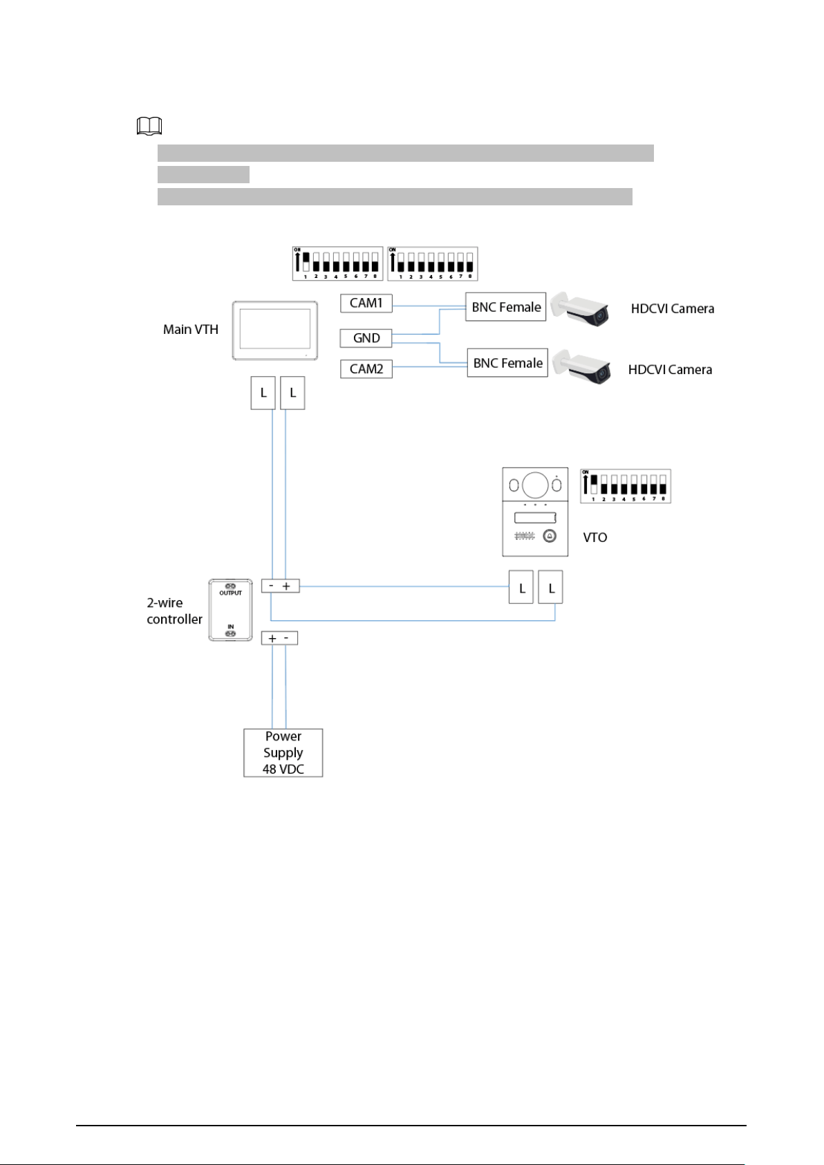
Wiring 1 VTO and 1 VTH
●
The two wires connected to the positive and negative terminals of OUT cannot be
short-circuited.
●
The line termination terminal and branch terminal are optional in this scenario.
Figure 2-1 Network diagram (without line termination terminal and branch terminal)
5
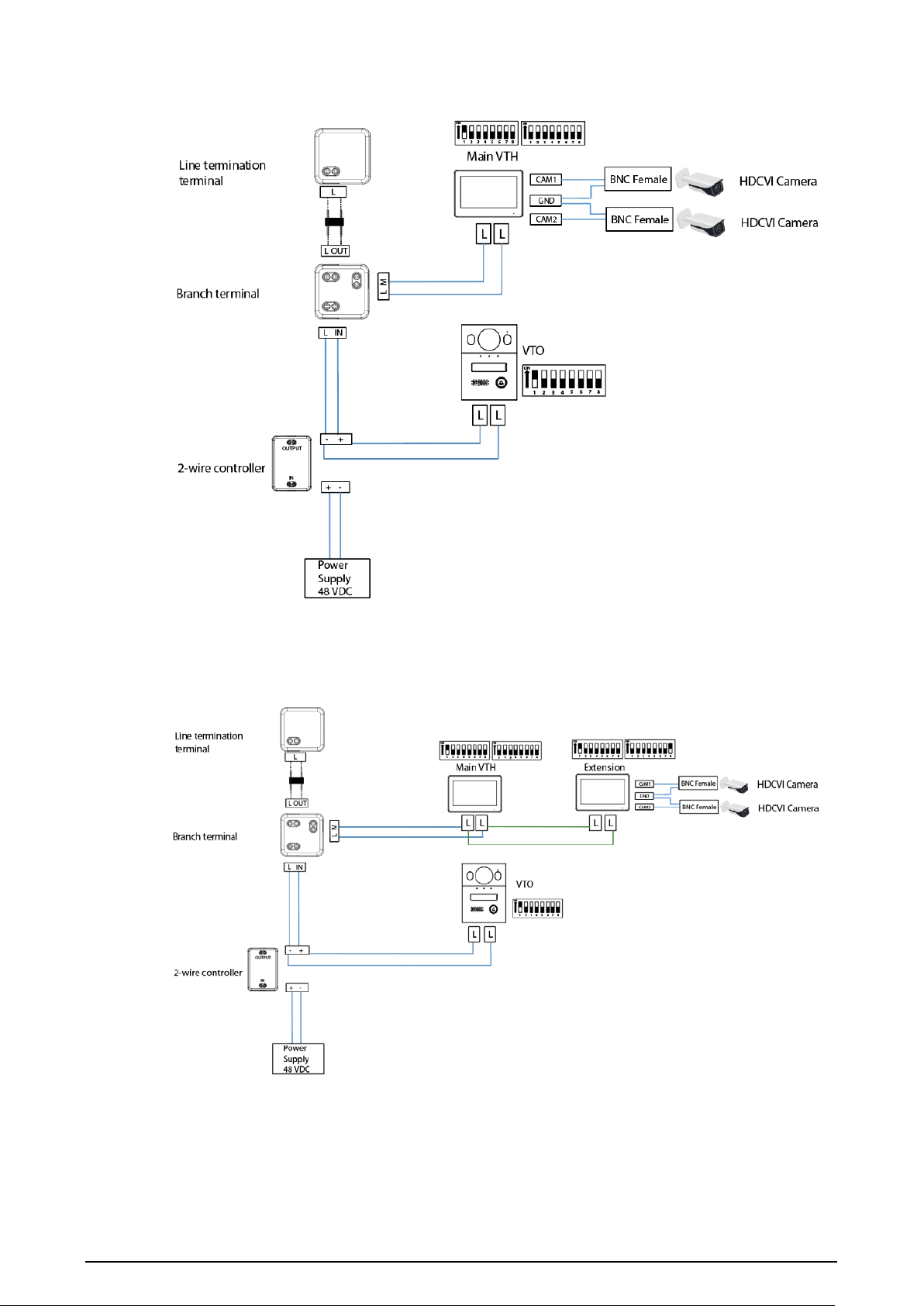
Figure 2-2 Network diagram (with line termination terminal and branch terminal)
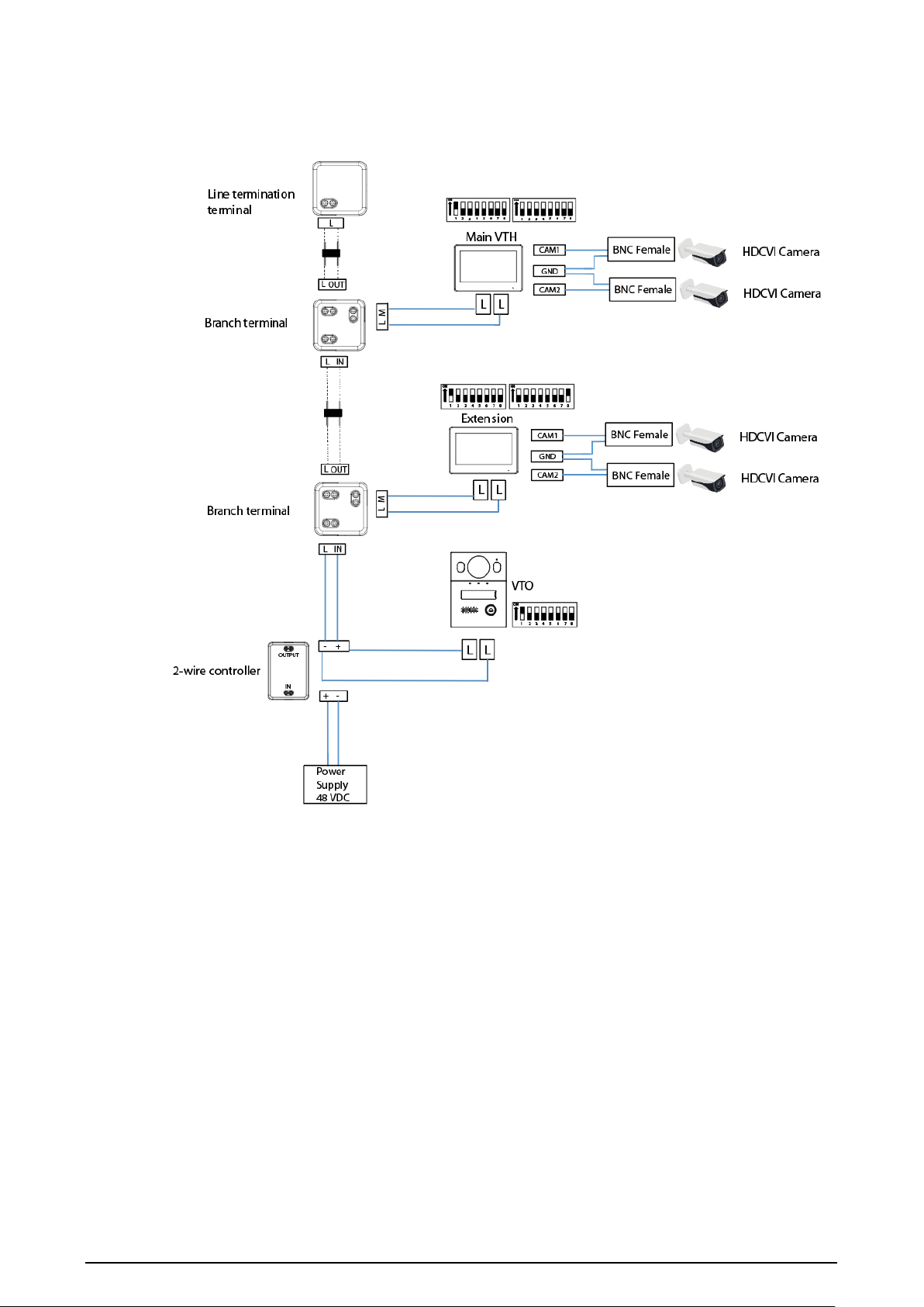
Wiring 1 VTO and 2 VTHs (Cascade Connection)
Figure 2-3 Network diagram
6
Wiring 1 VTO and 2 VTHs (Parallel Connection)
Figure 2-4 Network diagram
7
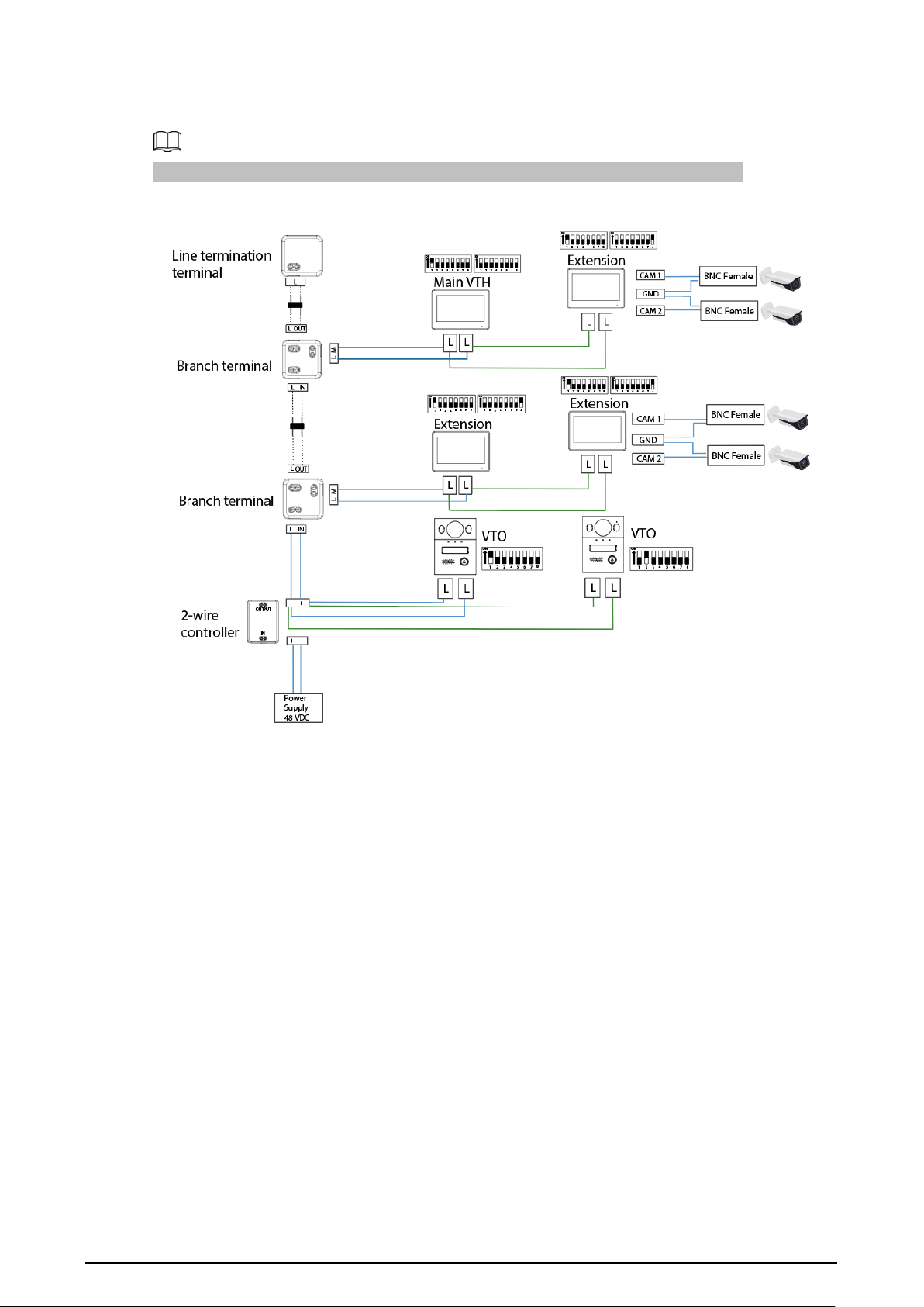
Wiring 2 VTOs and 4 VTHs
The DIP number of each VTO cannot be the same. Otherwise, the connection might fail.
Figure 2-5 Network diagram
8
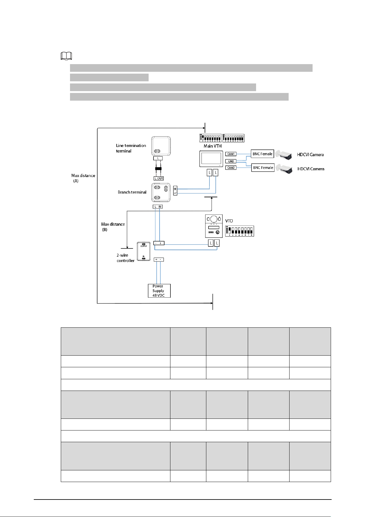
Wiring Distance Between the VTH and VTO
●
It is recommended that the distance between the line termination terminal and the 2-wire
controller do not exceed 3 m.
●
Max distance (A) refers to the distance between the VTH and the VTO.
●
Max distance (B) refers to the distance between the 2-wire controller and the VTH.
Figure 2-6 Max distance
Table 2-1 Wiring distance
RVV Cable AWG
Max.
Distance
(A)
Max.
Distance
(B)
Max.
Quantity of
Terminals
2 × 0.5 mm² 20 180 m 100 m 6
2 × 1.5 mm² 15 180 m 100 m 6
RVVP Cable
AWG
Max.
Distance
(A)
Max.
Distance
(B)
Max.
Quantity of
Terminals
2 × 0.5 mm² 20 150 m 100 m 6
Network Cable
AWG
Max.
Distance
(A)
Max.
Distance
(B)
Max.
Quantity of
Terminals
Cat5e Single Pair 24 100 m 35 m 6
9
Cat5e Single Pair 24 100 m 50 m 4
Multi Pair
Cable
24 200 m 100 m 6
Telephone Wire
AWG
Max.
Distance
(A)
Max.
Distance
(B)
Max.
Quantity of
Terminals
Telephone Wire 24 20 m 20 m 2
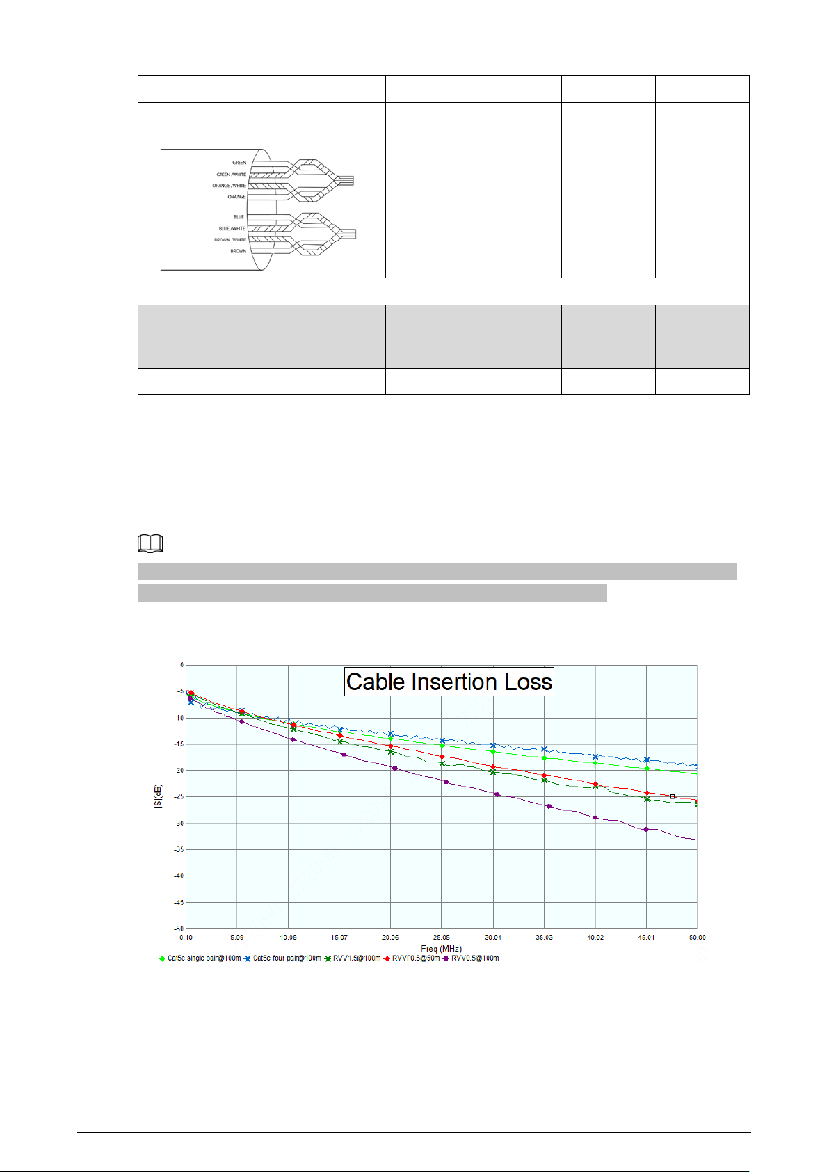
Cable Insertion Loss
Insertion loss refers to the situation of sending a signal from one end of the cable and receiving the
signal at the other end of the cable.
The calculation of cable insertion loss is as follows: Insertion Loss = 20 × Log (signal received/signal
sent)
The cable insertion loss followed is collected from the laboratory environment, and is for reference
only. The actual data might differ from that collected in the test environment.
Figure 2-7 Cable insertion loss

10
3 Structure
3.1 Front Panel
H series model with 7-inch screen
Figure 3-1 Front panel

11
H series model with 4.3-inch screen
Figure 3-2 Front panel
Table 3-1 Icons description
Icon Description
Unlock: Press to unlock the VTO when using it to make or receive a call
and perform monitoring.
●
Answer the call.
●
End the call.
12
G series model with 7-inch screen
Figure 3-3 Front panel
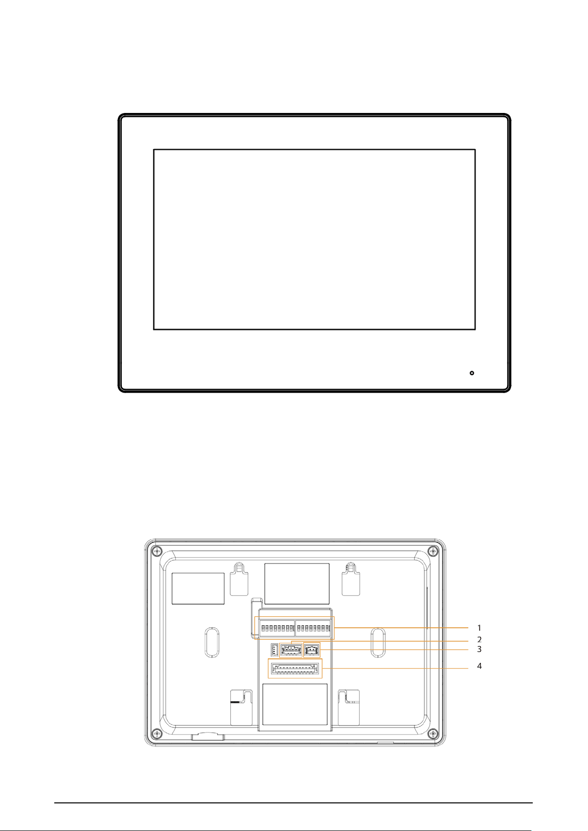
3.2 Rear Panel
H series model with 7-inch screen
Figure 3-4 Rear panel
13
Table 3-2 Rear panel description
No. Name Description
1
Dual In-line Package (DIP)
Switch
Manually change the position of the actuator to
that are corresponding to the function that you
want to program. DIP switches allow you to quickly
preconfigure the VTH a variety of settings or
operating modes.
2
RS-485 and power output
port
Used to connect to other devices; and connect to
the power supply.
3 2-wire hybrid port —
4 Alarm port
●
Used to connect to the alarm input and output
devices.
●
Include 6 alarm input ports, 1 alarm output port
and 2 camera ports.
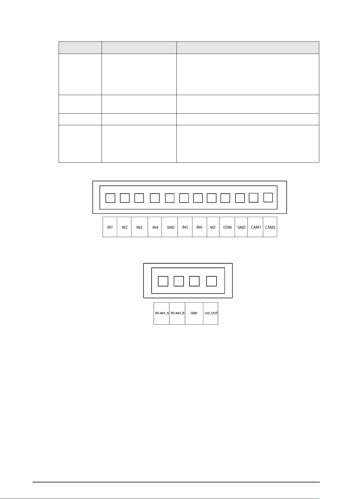
Figure 3-5 Alarm port
Figure 3-6 RS-485 and power output port

14
H series model with 4.3-inch screen
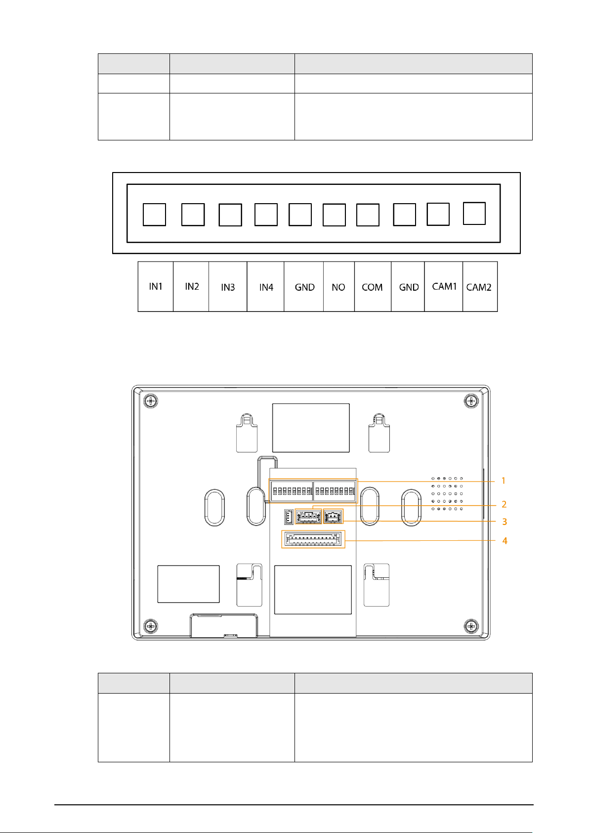
Figure 3-7 Rear panel
Table 3-3 Rear panel description
No. Name Description
1
Dual In-line Package (DIP)
Switch
Manually change the position of the actuator to
that corresponding to the function that you want to
program. DIP switches allow you to quickly
preconfigure the VTH to a variety of settings or
operating modes.
15
No. Name Description
2 2-wire hybrid port —
3 Alarm port
●
Connects to alarm input and output devices.
●
Include 4 alarm input ports, 1 alarm output port
and 2 camera ports.
Figure 3-8 Alarm port
G series model with 7-inch screen
Figure 3-9 Rear panel
Table 3-4 Rear panel description
No. Name Description
1
Dual In-line Package (DIP)
Switch
Manually change the position of the actuator to
that are corresponding to the function that you
want to program. DIP switches allow you to quickly
preconfigure the VTH a variety of settings or
operating modes.

16
No. Name Description
2
RS-485 and power output
port
Used to connect to other devices; and connect to
the power supply.
3 2-wire hybrid port —
4 Alarm port
●
Used to connect to the alarm input and output
devices.
●
Include 6 alarm input ports, 1 alarm output port
and 2 camera ports.
Figure 3-10 Alarm port
Figure 3-11 RS-485 and power output port
17
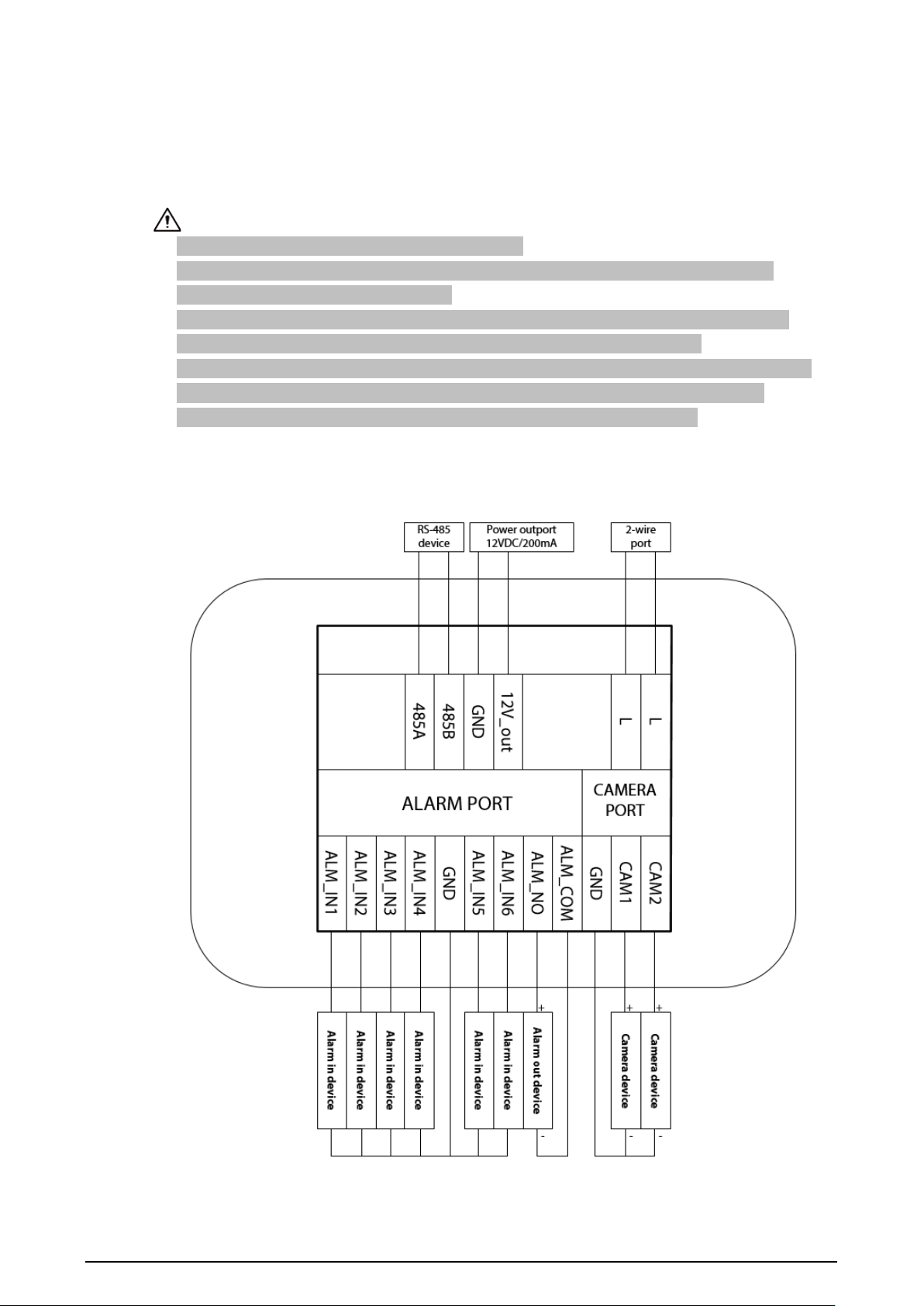
4 Installation and Wiring
This chapter introduces the wiring of the device.
●
The alarm input port is connected with dry contact.
●
Do not install devices in environments that have condensation, high temperatures, dust
corrosive substances and direct sunlight.
●
If the device behaves abnormally after you turn it on, cut off the power supply at once and
unplug the network cable. Power on again after you finish resolving the issue.
●
Installation should be done by professional teams. Do not disassemble or repair the device by
yourself to avoid damaging the device. Contact after-sales service if you need any help.
●
The recommended installation height of the device is 1.6 m from the ground.
The VTH with a 7-inch screen
Figure 4-1 Port description
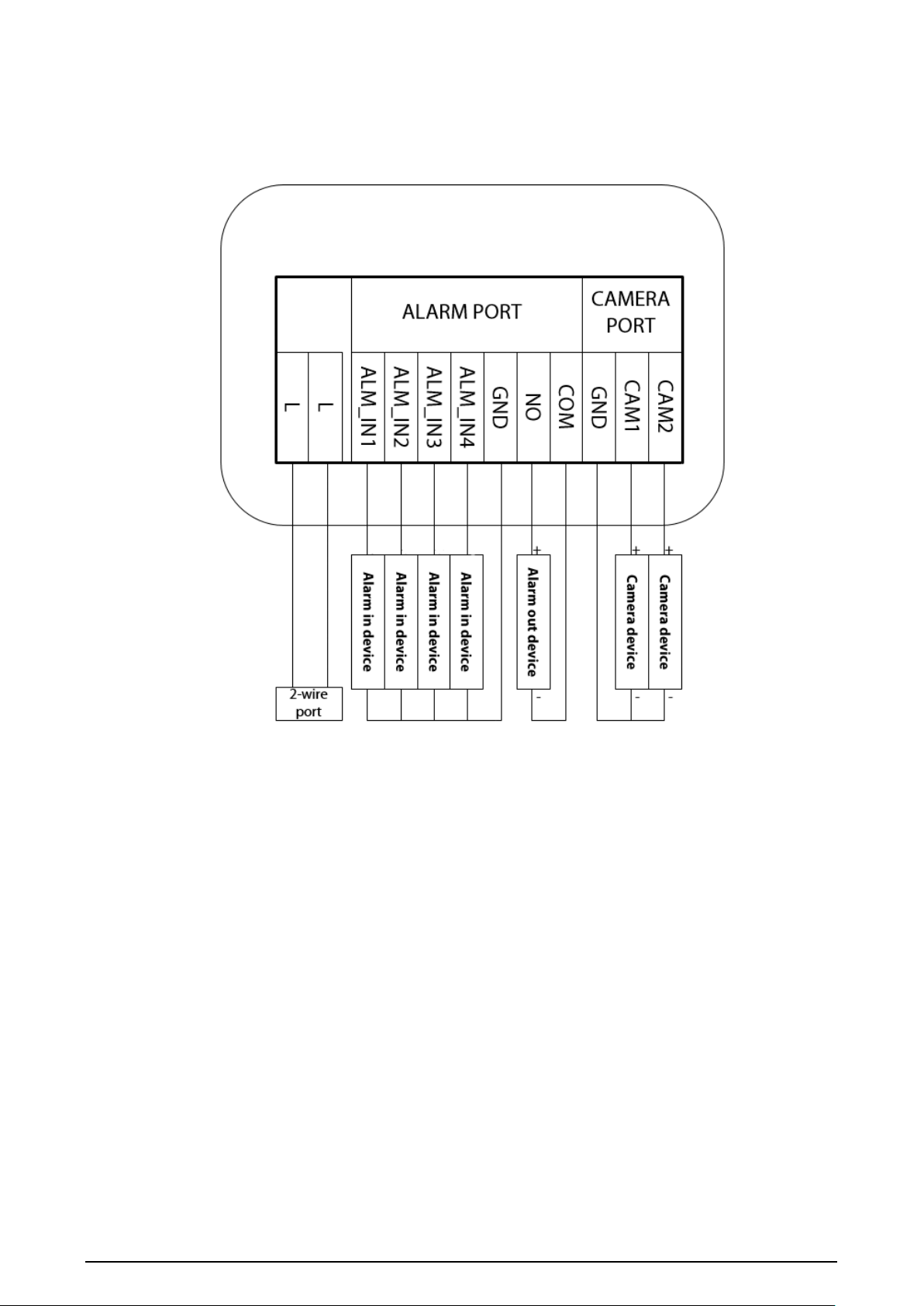
18
The VTH with a 4.3-inch screen
Figure 4-2 Port description
19
5 DIP Configuration
5.1 DIP Switch Basic Mapping Rule
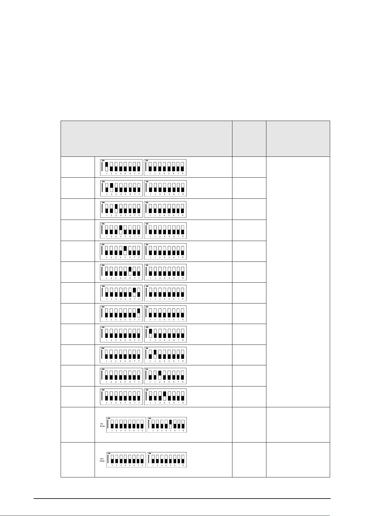
Table 5-1 DIP Switch mapping relations and function
DIP Switch No.
Corresp
onding
Address
No.
Function
DIP 1
1
●
Used to
program the
address of the
VTH.
●
You can set a
maximum of
4,094 VTH
address by
using the 12 DIP
switches.
DIP 2
2
DIP 3
4
DIP 4
8
DIP 5
16
DIP 6
32
DIP 7
64
DIP 8
128
DIP 9
256
DIP 10
512
DIP 11
1024
DIP 12
2048
DIP 13
—
ON
: Connect to
HDCVI camera
through Unshielded
Twisted Pair (UTP).
DIP 13
—
OFF
: Connect to the
HDCVI camera
through the coax
cable.
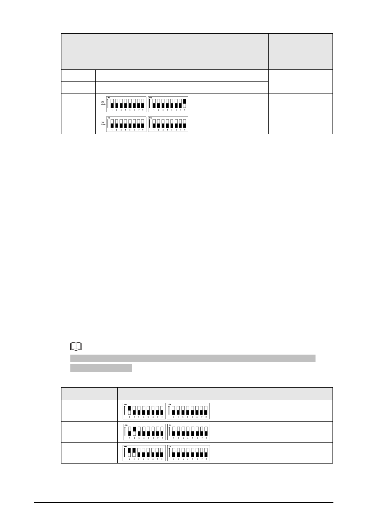
20
DIP Switch No.
Corresp
onding
Address
No.
Function
DIP 14
— —
Reserved.
DIP 15
— —
DIP 16
—
ON
: Set the VTH as
the extension.
DIP 16
—
OFF
: Set the VTH as
the main VTH.
5.2 DIP Switch Coding Rules
This section introduces how to configure the address of a VTH through the coding rules of DIP
switches. By setting the switches in combination, you can get any value from 1-4,094.
1. Find the mapping relationship between the DIP switch number and the address number you
plan to configure from the table.
It follows a calculation rule that combines only the numbers listed in the
Address No.
to form a
new address number.
2. Manually move the actuators corresponding to the DIP switches to the
ON
status, so that the
address of the VTH can be configured.
For example, if you want to set your VTH address as 4, you need to first find the mapping
relationship (DIP 3 equals to the address number of 4) in the table, and then manually move the
actuator of DIP 3 to the
ON
status. If you want to set your VTH address as 3, you need to do the
calculation (1+2=3; which equals to the value of DIP 1 and DIP 2 combined together in the
mapping relationship), and manually move both the actuator of DIP 1 and DIP 2 to the
ON
status.
If you want to set your VTH address as 133, you need to do a more complex calculation
(128+4+1=133, which equals to the value of DIP 8, DIP 3 and DIP 1 combined together in the
mapping relationship), and then manually move the actuator of DIP 8, DIP 3 and DIP 1 to the
ON
status.
Here is the list of commonly used VTH addresses (1-20) and their corresponding DIP switch
number combinations.
Table 5-2 Common VTH addresses (1-20) and DIP switch numbers
VTH Address DIP Switch Combination Coding Rule
1 DIP 1
2
DIP 2
3
DIP 2+ DIP 1
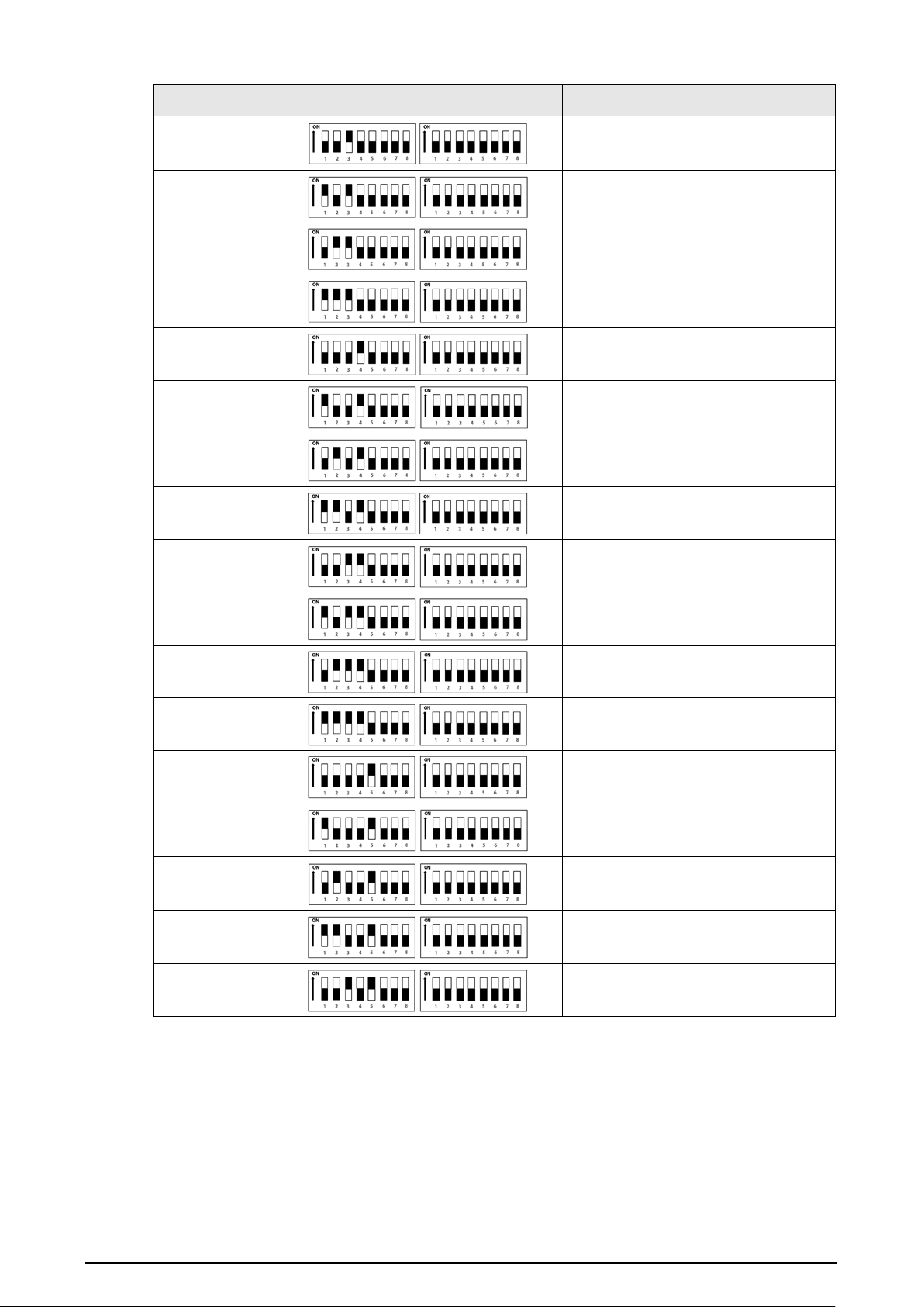
21
VTH Address DIP Switch Combination Coding Rule
4
DIP 3
5 DIP 3 + DIP 1
6
DIP 2 + DIP 3
7 DIP 3 + DIP 2 + DIP 1
8
DIP 4
9
DIP 4 + DIP 1
10
DIP 4 + DIP 2
11
DIP 4 + DIP 2+ DIP 1
12 DIP 4 + DIP 3
13 DIP 4 + DIP 3+ DIP 1
14
DIP 4 + DIP 3+ DIP 2
15 DIP 4 + DIP 3 + DIP 2+DIP 1
16
DIP 5
17
DIP 5 + DIP 1
18 DIP 5 + DIP 2
19
DIP 5 + DIP 2+ DIP 1
20
DIP 5 + DIP 3
22
6 VTH Operations
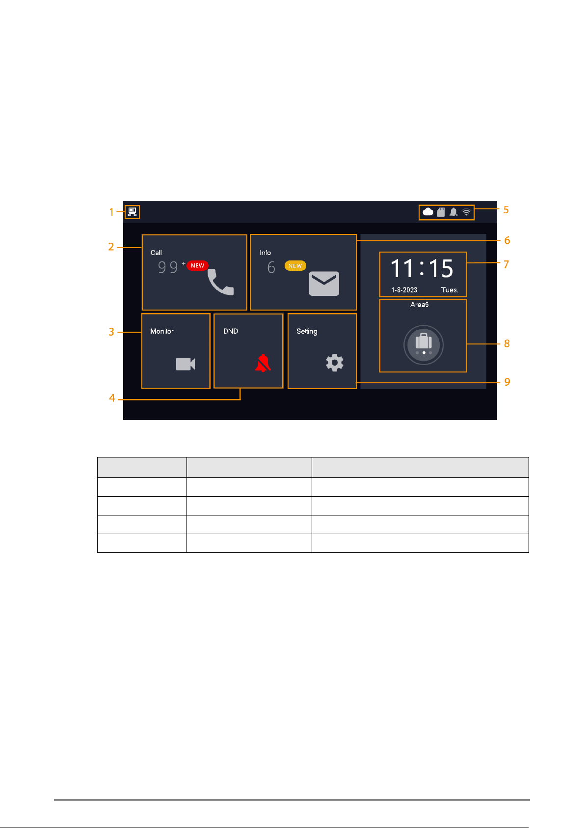
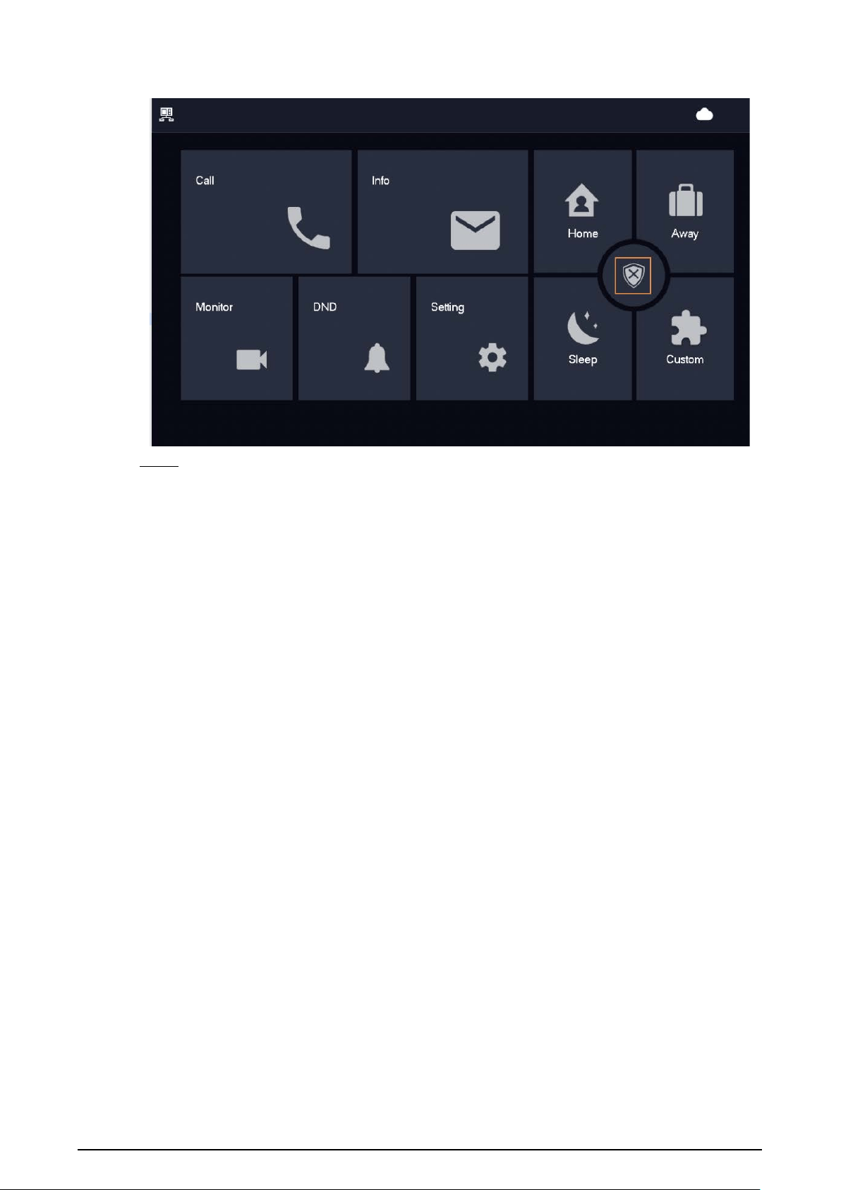
6.1 Home Screen
Figure 6-1 Home screen
Table 6-1 Home screen description
No. Name Description
1 Main VTH If there is no icon, this is a sub VTH.
2 Call Call other VTOs, or DMSS users.
3 Monitor Monitor VTOs and HDCVI cameras.
4 DND Enable to not receive any calls.
23
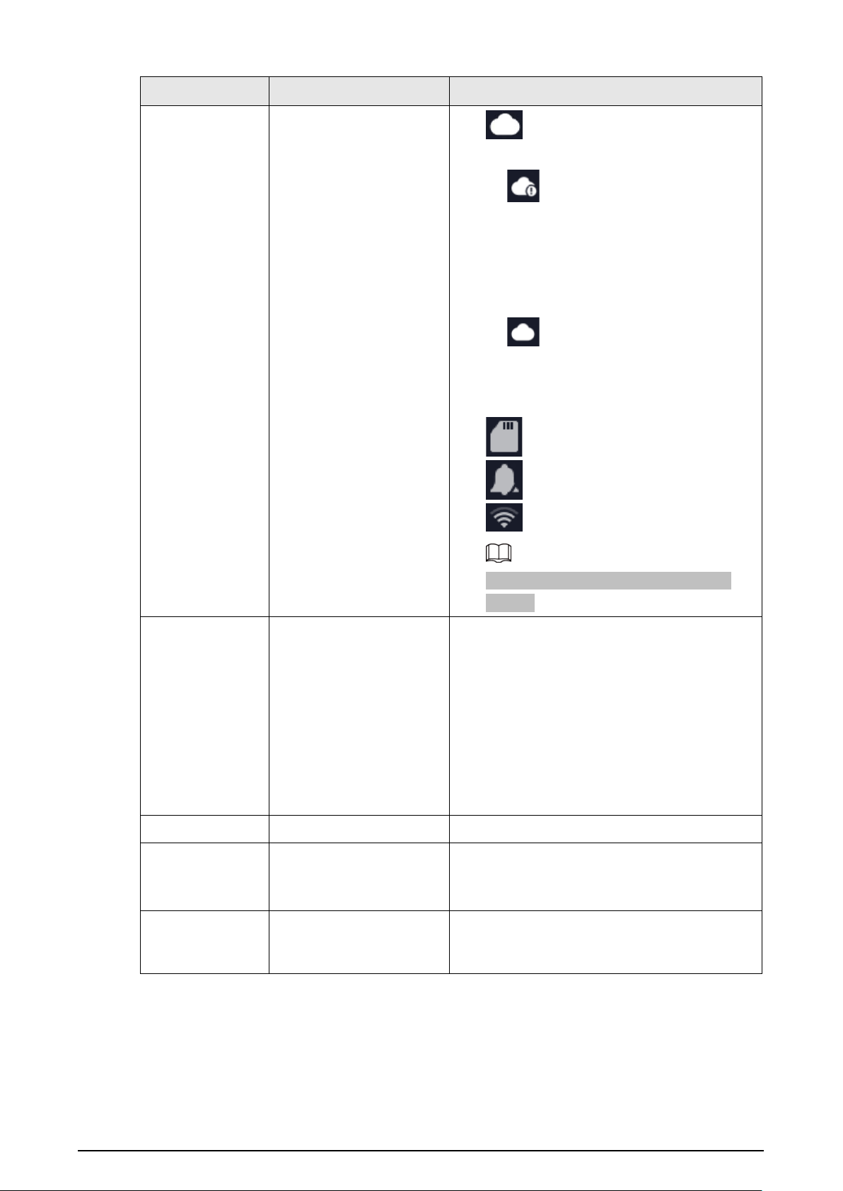
No. Name Description
5 Icons
●
: Displays the network connection
status.
◇
: The icon appears when the
device does not meet one of the
following standards. The cloud function
is enabled, or the VTH is connected to a
Wi-Fi that allows it to visit external
networks.
◇
: The icon appears only when the
cloud function is enabled, and the VTH
has connected to a Wi-Fi that allows the
device to visit external networks.
●
: An SD card is inserted.
●
: The DND is enabled.
●
: The Wi-Fi is connected.
The Wi-Fi function is available on select
models.
6 Info
●
View, delete and clear security alarm
information.
●
When an SD card is inserted into the VTH, 3
tabs will be displayed:
Alarm
,
Guest MSG
,
and
Guest Video
. You can view, delete and
clear the messages.
●
When the VTH has an SD card, the
Video
Pic
tab will be displayed. You can view,
delete and clear the videos and pictures.
7 Time and Date —
8 Arm/Disarm
●
Display unread alarm information.
●
Tap to select an arm mode:
Sleep
,
Away
,
Home
or
Custom
.
9 Setting
Tap the icon to configure the settings for ring,
alarm, arm mode, general, WLAN and
password.
6.2 Call
Manage calls and view call records.
24
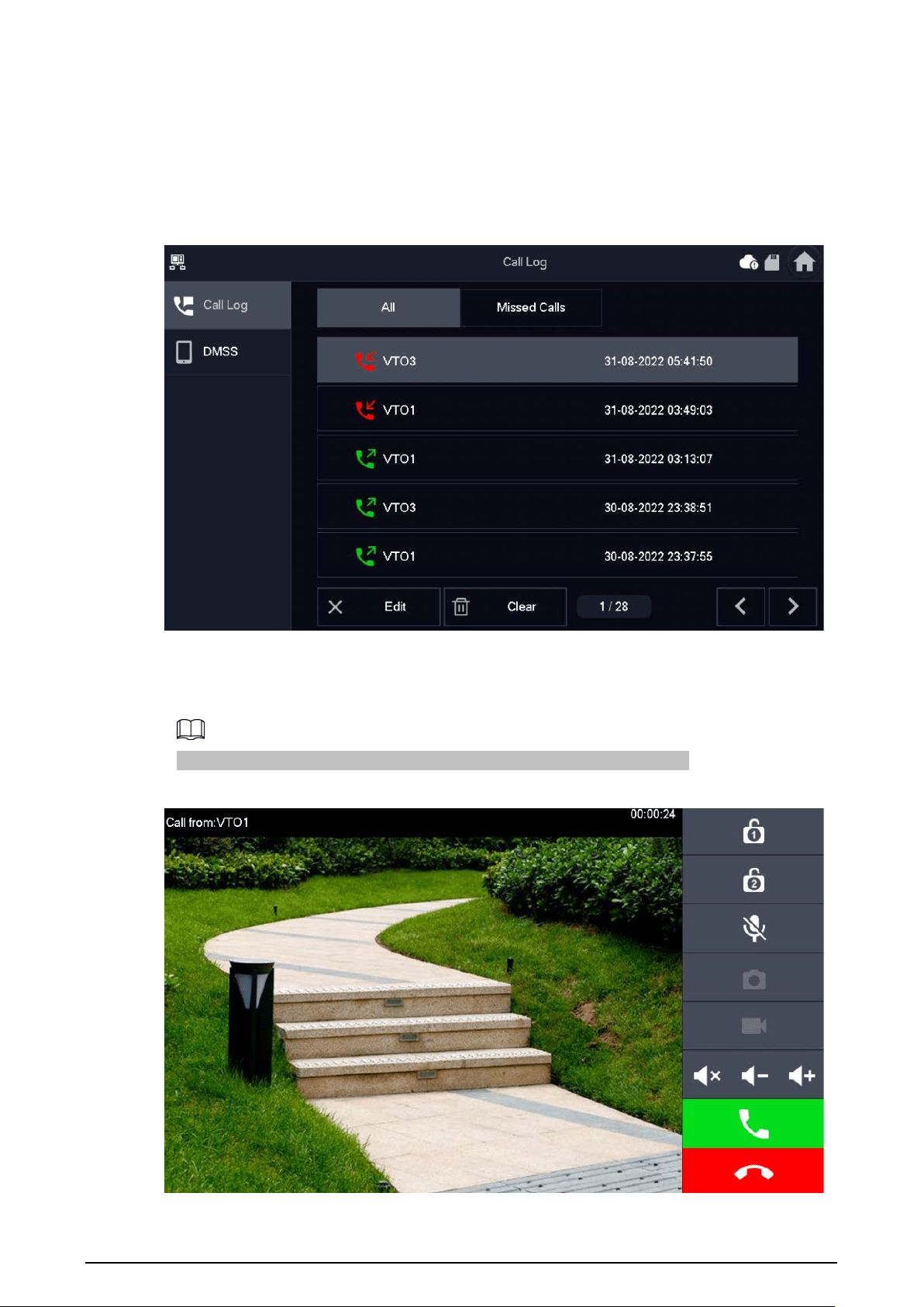
6.2.1 Call Logs
Select
Call
>
Call Log
to view and manage call records.
●
All
: All of the call records.
●
Missed Calls
: Calls that were missed.
Figure 6-2 Call log
●
Call back
: Tap a call record to call back.
●
Delete
: Tap
Edit
, and then tap
Delete
to delete a record.
●
Clear
: Clear all record from the current tab (
All
or
Missed Calls
).
If storage is full, the earliest records will be overwritten. Back up the records.
Figure 6-3 Calling VTO (the device with a 7-inch screen)
25
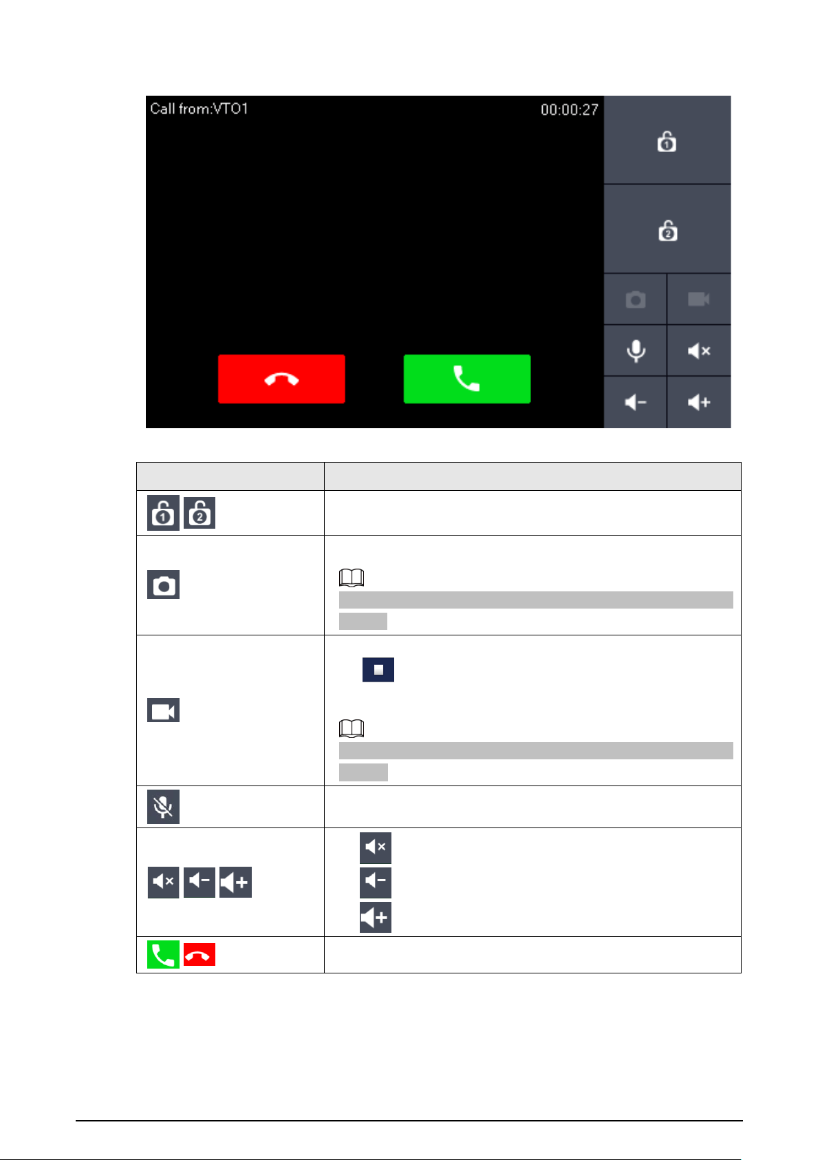
Figure 6-4 Calling VTO (the device with a 4.3-inch screen)
Table 6-2 Icon description
Icon Description
/ Remotely unlock the door where the VTO is located.
Take snapshots.
An SD card is needed to use this function. Otherwise, the icon will
be gray.
Tap to start recording. It will stop when the call ends or when you
tap
.
If the SD card is full, the earliest videos will be overwritten.
An SD card is needed to use this function. Otherwise, the icon will
be grey.
Tap to mute the sound from the VTH.
/ /
●
: Mute the sound.
●
: Lower the volume.
●
: Increase the volume.
/
Receive and end calls.
26
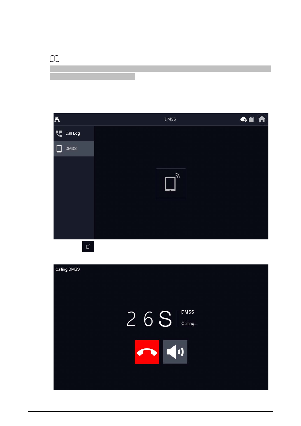
6.2.2 VTH Calling DMSS
Make calls to the DMSS app.
To call DMSS, you must have added the VTH to the DMSS account that you are using. For details, see
"6.5.6.2.1 Creating Network Password".
Procedure
Step 1 Select
Call
>
DMSS
.
Figure 6-5 DMSS
Step 2 Tap to call the DMSS app account that the VTH has bonded with.
Figure 6-6 Calling DMSS
27
●
: Hang up the call.
●
: Mute the call.
6.3 Information
View and manage the information, including alarm records, guest messages and video pictures.
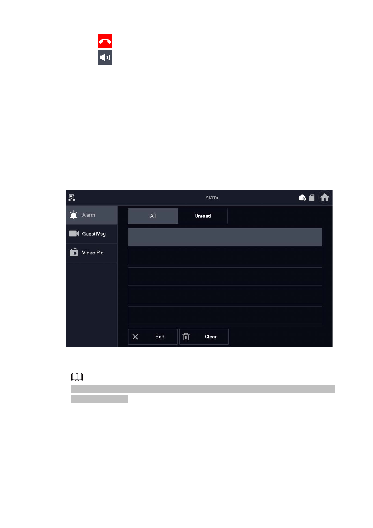
6.3.1 Alarm information
When an alarm is triggered, there will be 15 s alarm sound. The alarm information will be uploaded
to the alarm record screen.
Select
Info
>
Alarm
, and then you can view and manage all alarm records.
Figure 6-7 Alarm
●
Edit
: Edit the alarm records you selected.
●
Delete
: Delete the alarm records you selected.
After tapping
Edit
and selecting the records, the icon becomes
Del
, and then you can delete the
selected the records.
●
Clear
: Delete all of the alarm records.
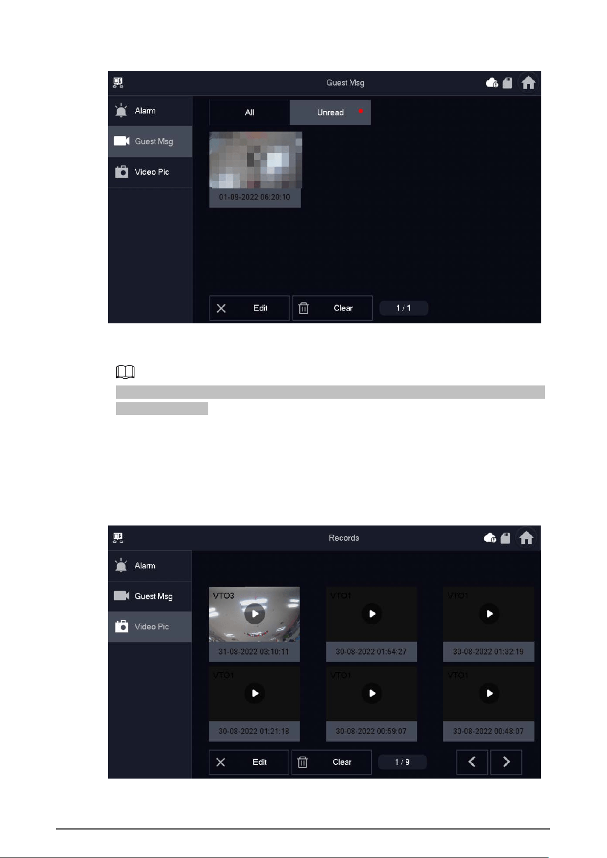
6.3.2 Guest Message
Select
Info
>
Guest MSG
, and then you can view and manage all messages.
28
Figure 6-8 Guest messages
●
Edit
: Edit the guest message records you selected.
●
Delete
: Delete the guest message records you selected.
After tapping
Edit
and selecting the records, the icon becomes
Del
, and then you can delete the
selected the records.
●
Clear
: Delete all of the guest message records.
6.3.3 Video Pictures
Select
Info
>
Video Pic
, and then you can view and manage the pictures and videos.
Figure 6-9 Video pictures
●
Edit
: Edit the video picture records you selected.
29
●
Delete
: Delete the video picture records you selected.
After tapping
Edit
and selecting the records, the icon becomes
Del
, and then you can delete the
selected the records.
●
Clear
: Delete all the video picture records.
6.4 Monitoring
View the images recorded from the VTO or HDCVI camera.
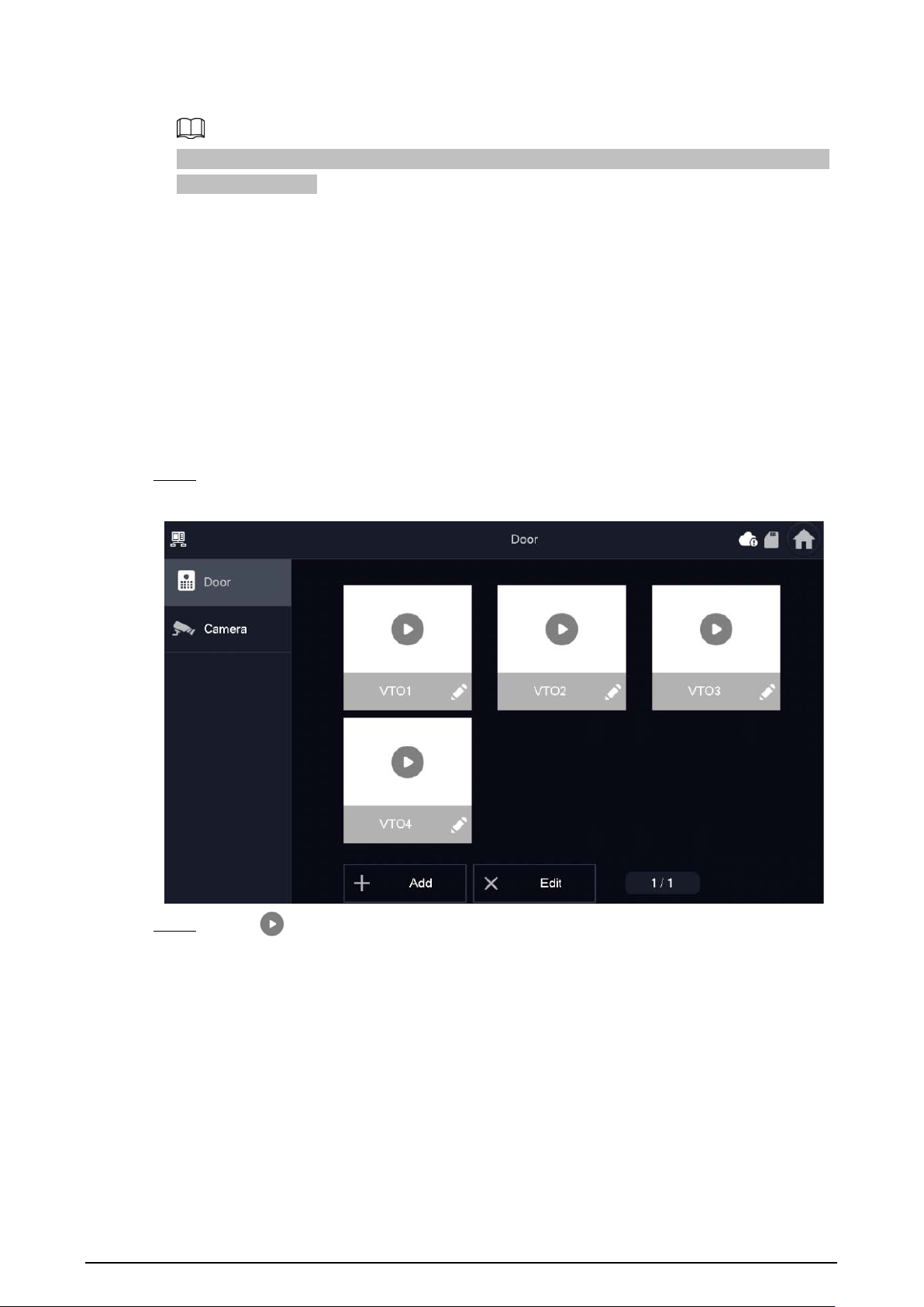
6.4.1 Monitoring VTO
Procedure
Step 1 Select
Monitor
>
Door
.
Figure 6-10 VTO
Step 2 Tap
to monitor the VTO you selected.
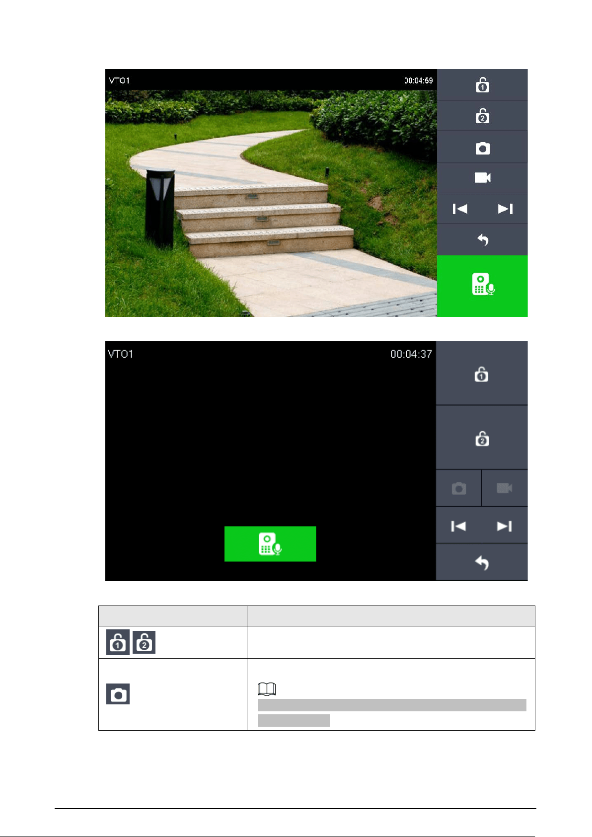
30
Figure 6-11 Monitoring VTO (the device with a 7-inch screen)
Figure 6-12 Monitoring VTO (the device with a 4.3-inch screen)
Table 6-3 Icon description
Icon Description
/ Remotely unlock the door where the VTO is located.
Take snapshots.
An SD card is needed to use this function. Otherwise, the icon
would turn grey.

31
Icon Description
Tap to start recording, and it will stop when the call is
completed or after you tap
.
If the SD card is full, the oldest videos will be overwritten.
An SD card is needed to use this function. Otherwise, the icon
would turn grey.
/
If the VTH is connected to multiple VTOs or HDCVI camera, tap
or to switch between devices.
Exit monitoring.
Tap to speak to the VTO, and tap again to stop.
Related Operations
●
Add
: To add new VTOs. Enter the ID number and the name of the VTO, and then tap
OK
.
Figure 6-13 Add new VTO
●
Delete
: To delete the selected VTOs.
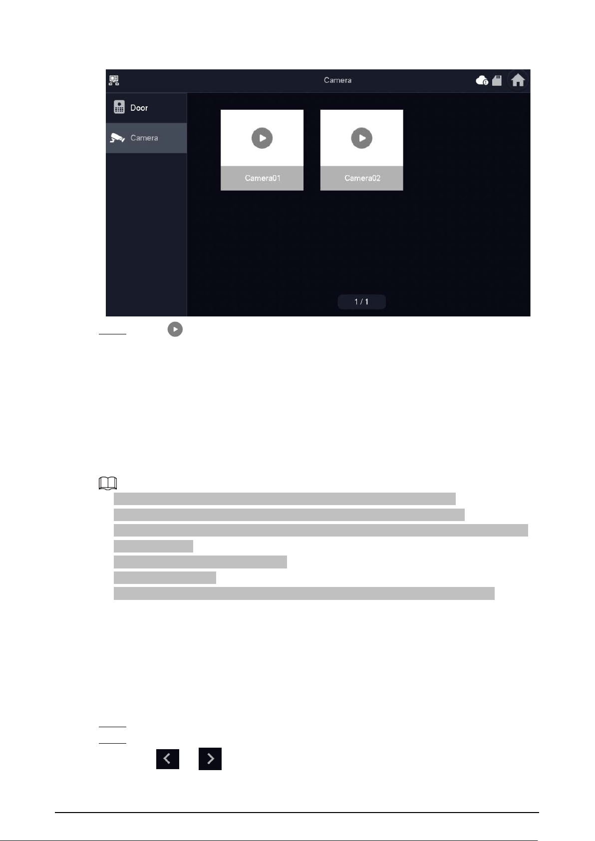
6.4.2 Monitoring Camera
Procedure
Step 1 Select
Monitor
>
Camera
.
32
Figure 6-14 Camera
Step 2 Tap
to monitor the camera you selected.
6.5 Setting
6.5.1 Ring Settings
Set VTO ring, alarm ring and other rings.
●
There is an SD card on the VTH, and users can import ring tones to the SD card.
●
Ring tones must be stored in the /Ring folder at the root directory of the SD card.
●
Audio files must be .pcm files (audio files of other formats cannot be played if you change their
extension names).
●
Audio file size must be less than 100 KB.
●
Ring tone format: .pcm.
●
You can only customize 10 ring tones. Other ring tones will not be displayed at the VTH.
6.5.1.1 VTO Ring
Background Information
Set a ring for the connected VTO, and support to set maximum 14 VTOs.
Procedure
Step 1 Tap
Setting
.
Step 2 Select
Ring
>
VTO Ring
.
●
or : Tap the icons to page up and down.
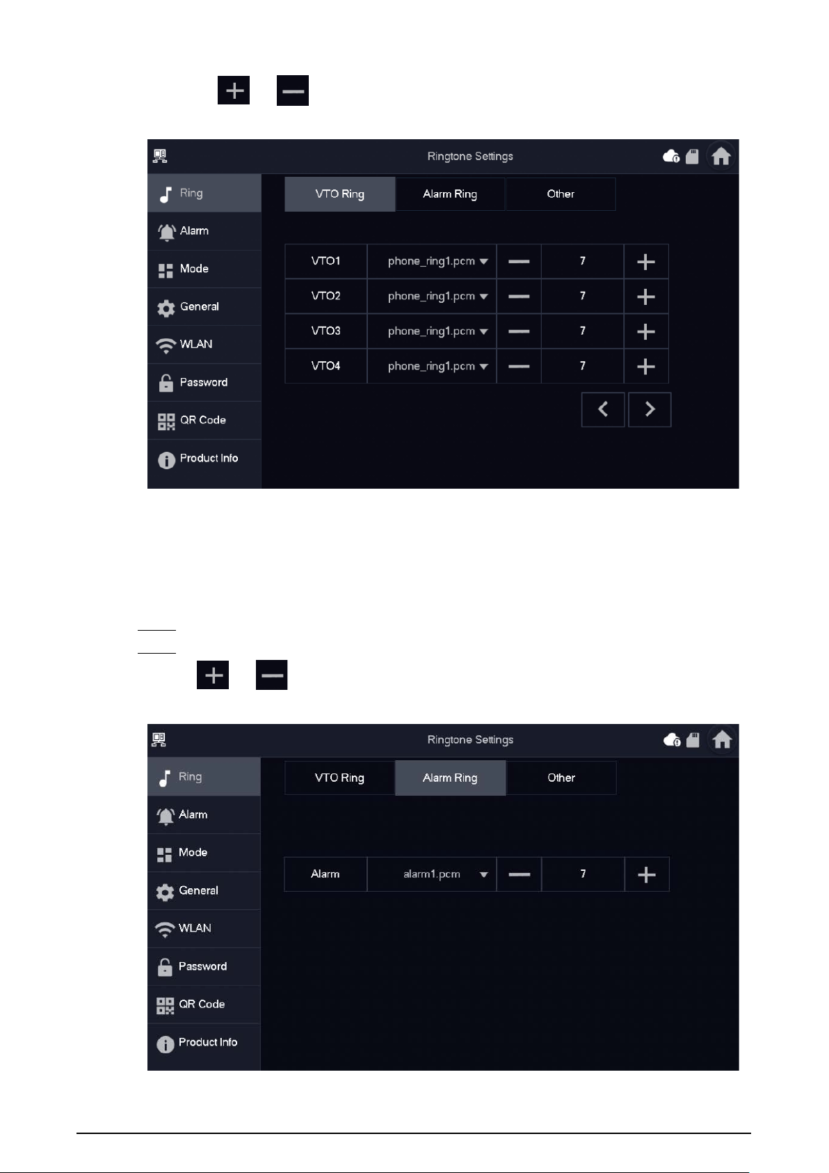
33
●
or : Tap the icons to adjust the VTO ring volumes.
Figure 6-15 VTO ring
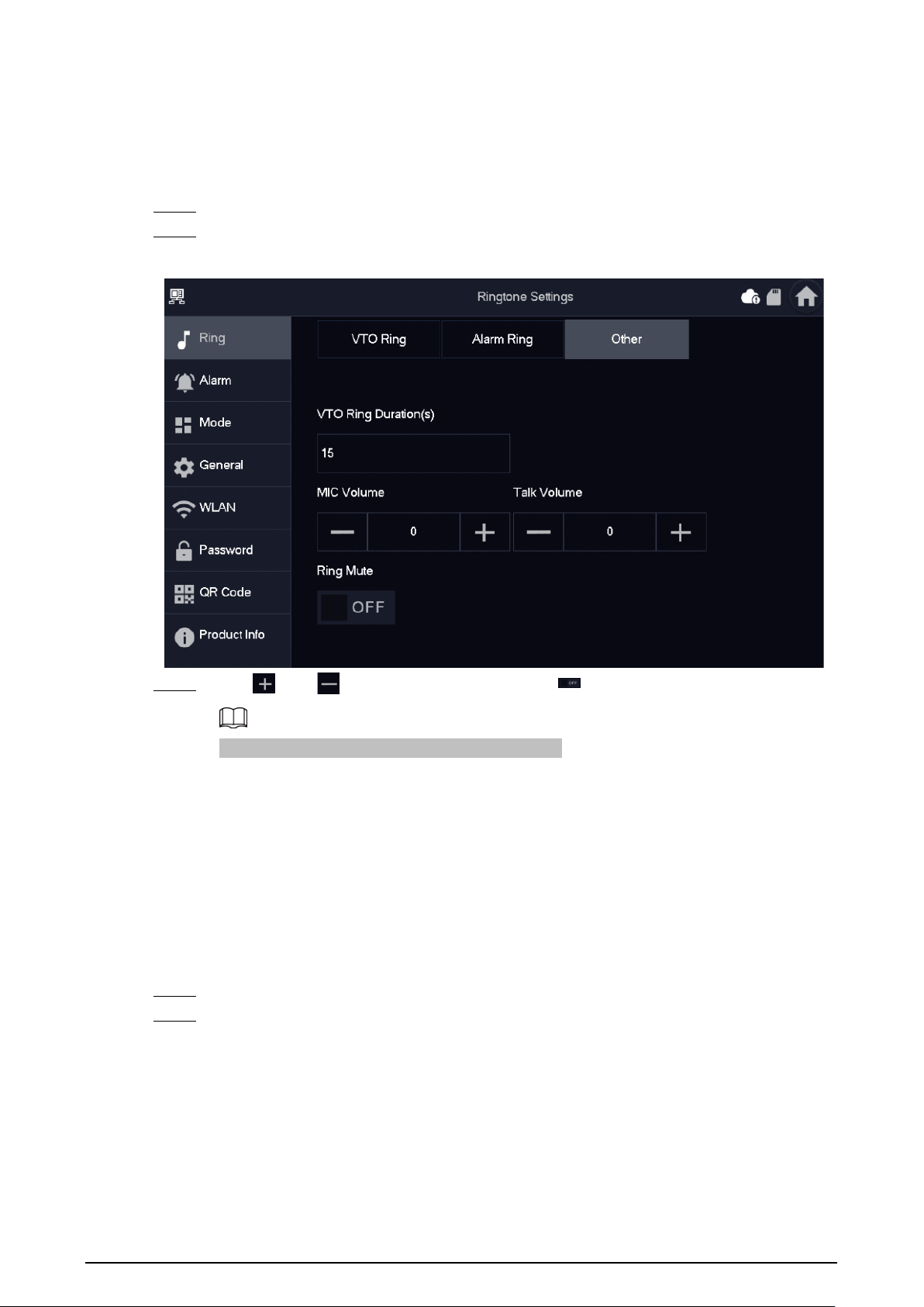
6.5.1.2 Alarm Ring
Set the ring when the VTH gives an alarm.
Procedure
Step 1 Tap
Setting
.
Step 2 Select
Ring
>
Alarm Ring
.
or : Tap the icons to adjust the VTO ring volumes.
Figure 6-16 Alarm ring
34
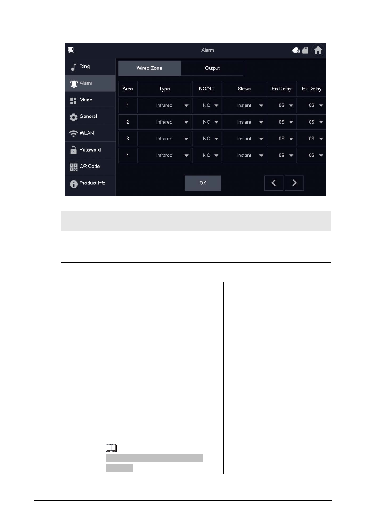
6.5.1.3 Other Ring
Set VTO ring time, MIC volume, talk volume and ring mute setting.
Procedure
Step 1 Tap
Setting
.
Step 2 Select
Ring
>
Other
.
Figure 6-17 Other ring
Step 3 Tap
and to set the time or volume. Tap to enable
Ring Mute
.
VTO ring time: ring time when a VTO calls this VTH.
6.5.2 Alarm Setting
6.5.2.1 Wired Zone
Set zone type, NO/NC, alarm status and delay. You can set 6 zones at most.
Procedure
Step 1 Tap
Setting
.
Step 2 Select
Alarm
>
Wired Zone
.
35
Figure 6-18 Wired zone
Table 6-4 Parameter description
Paramete
r
Description
Area The number cannot be modified.
NO/NC
Select NO (normally open) or NC (normally closed) according to detector type. It
shall be the same as detector type.
Type
Select corresponding type according to detector type, including IR, gas, smoke,
urgency button, door, burglar alarm, perimeter and doorbell.
Status
●
Instant Alarm
: After armed, if an alarm
is triggered, the device produces siren
at once and enters alarm status.
●
Delay Alarm
: After armed, if an alarm
is triggered, the device enters alarm
status after a specified time, during
which you can disarm and cancel the
alarm.
●
Bypass
: Alarm will not be triggered in
the area. After disarmed, this area will
restore to normal working status.
●
Remove
: The area is invalid during
arm/disarm.
●
24 Hour
: Alarm will be triggered all the
time in the area regardless of arm or
disarm.
A zone in
Remove
status cannot be
bypassed.
—
36
Paramete
r
Description
Enter
Delay
After entering delay, when armed area
triggers an alarm, entering armed area
from non-armed area within the delay time
period will not lead to linkage alarm.
Linkage alarm will be produced if delay
time comes to an end and it is not
disarmed.
Delay is only valid to the areas of
Delay Alarm
.
Exit Delay
After arm,
Delay Alarm
area will enter arm
status at the end of
Exit Delay
.
If multiple areas set the exit delay,
interface prompt will conform to
maximum delay time.
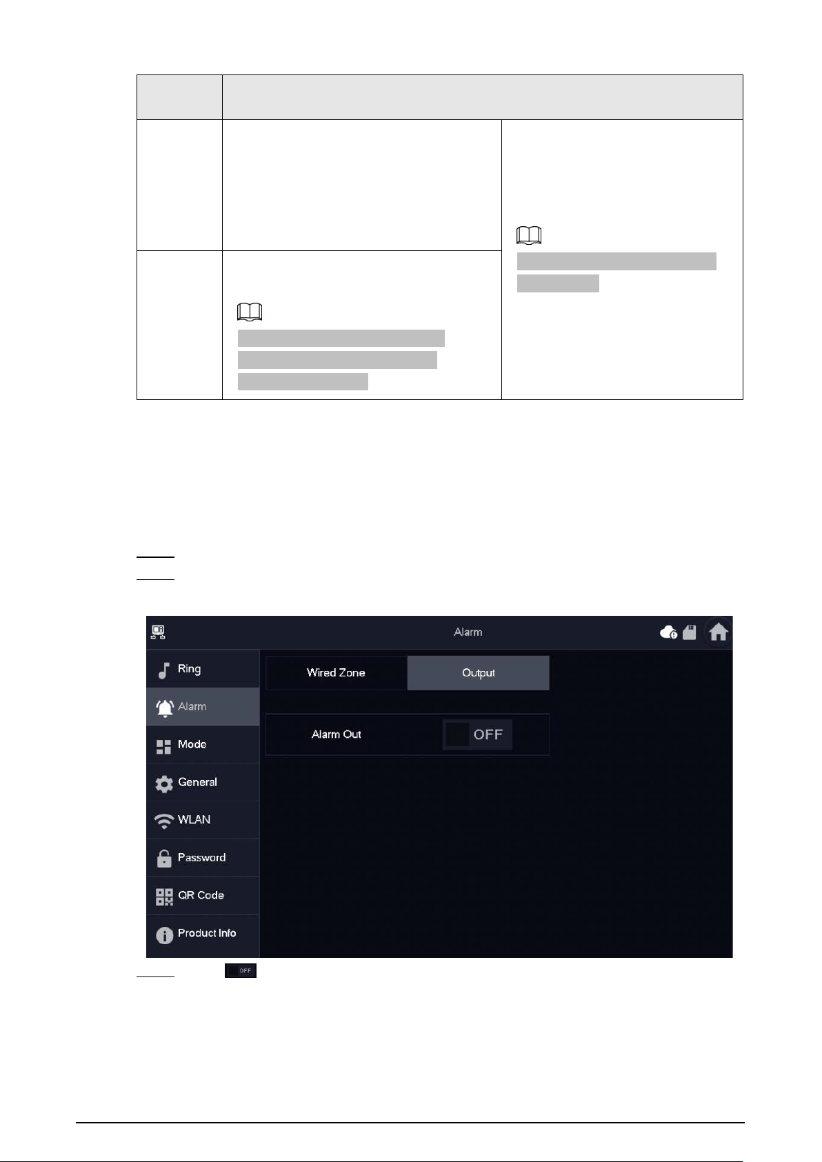
6.5.2.2 Alarm Output
After enabling alarm output, when other devices call this VTH, the alarm output device will output
alarm information.
Procedure
Step 1 Tap
Setting
.
Step 2 Select
Alarm
>
Output
.
Figure 6-19 Alarm output
Step 3 Tap to enable the alarm output function.
37
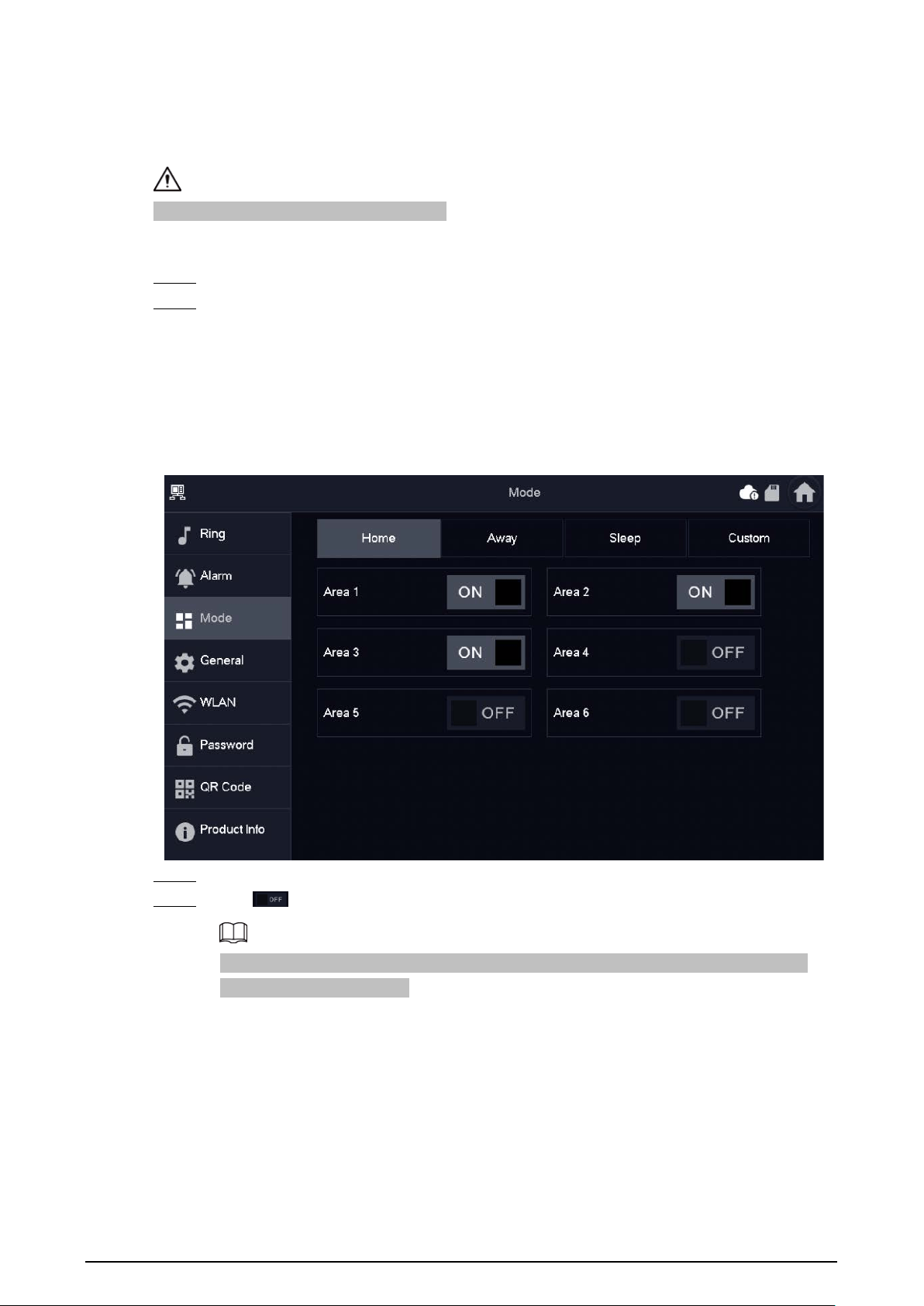
6.5.3 Arm Mode Setting
Set area on/off status under different modes.
Area mode can only be set in disarm status.
Procedure
Step 1 Tap
Setting
.
Step 2 Select
Mode
.
●
Home
: An arming mode that allows you to arm the system when inside the area of the
alarm system.
●
Away
: Arm the system when you leave the area of the alarm system.
●
Sleep
: An alarming mode that allows you to arm the system in the sleep time.
●
Custom
: Arm the system based on your customized needs.
Figure 6-20 Mode setting
Step 3 Select the arm mode you want to configure in the tabs.
Step 4 Tap in every area to add it into arm mode.
Multiple areas can be added into one arm mode at the same time, and one area can be
added into different modes.
38
6.5.4 General Setting
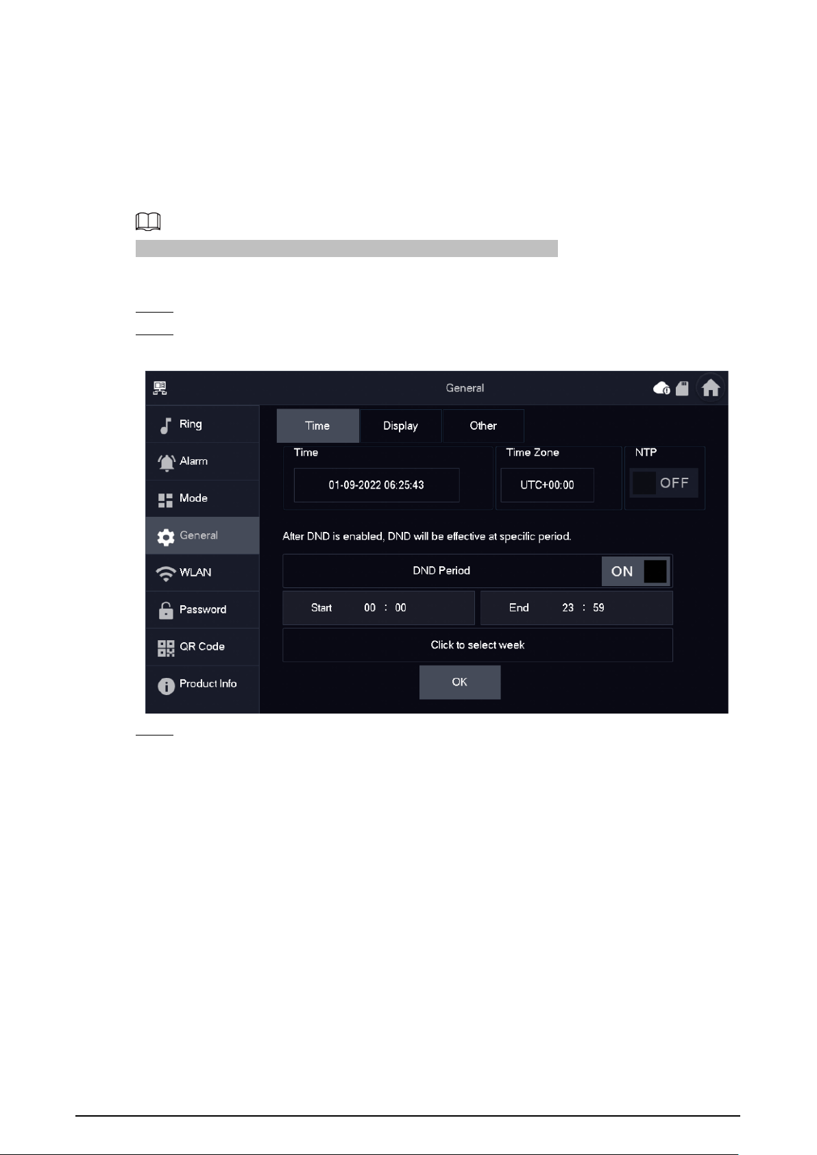
6.5.4.1 Time and DND
Set VTH system time, time zone and DST.
Parameters at this screen can be set on both main VTH and extensions.
Procedure
Step 1 Tap
Setting
.
Step 2 Select
General
>
Time
.
Figure 6-21 Set time and time zone
Step 3 Set time parameter.
●
Enable
NTP
, the VTH will synchronize time with the NTP server automatically; turn it off
to set time or time zone manually.
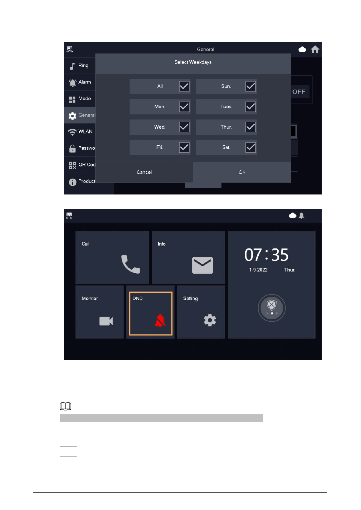
●
Enable
DND period
, set start and end time or tap
Click to select week
to select the
day(s), and you will not receive any call or message during this period, and then tap
OK
.
39
Figure 6-22 DND period
Figure 6-23 DND enabled
6.5.4.2 Display
Set VTH screen brightness, screenclose time and clean the screen.
The snapshots are for reference only, and might differ from the actual screen.
Procedure
Step 1 Tap
Setting
.
Step 2 Select
General
>
Display
.

40
Figure 6-24 Display
Step 3 Set parameters.
●
Brightness
: The brightness of the VTH screen. If the screen display is brighter or darker
than your expectation, you can adjust the brightness by taping
or .
●
Screenclose Time
: The screen will automatically turn off when it reaches the time limit
for being idle. If it is longer or shorter than your expected time limit, you can adjust the
time by taping
or .
●
Clean
: Tap the icon, and then the screen will be locked for 30 seconds. During the
period, clean the screen.
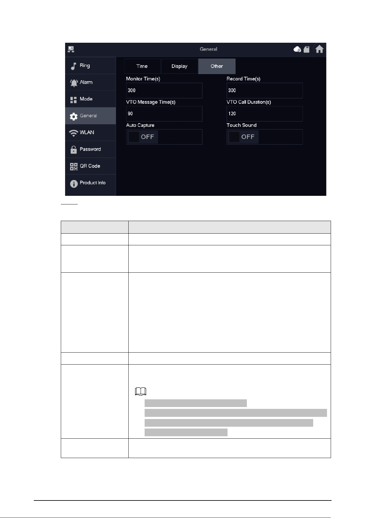
6.5.4.3 Other
You can configure the monitoring time, recording time, VTO message time, VTO call time, auto
capture and touch sound.
For Sub VTHs, you can configure Auto Capture, Touch Sound, Record Time, VTO Call Duration and
Touch Sound. But VTO Message Time cannot be configured, it is 90 seconds by default. All the
parameters can be configured for the main VTH.
Procedure
Step 1 Tap
Setting
.
Step 2 Select
General
>
Other
.
41
Figure 6-25 Other
Step 3 Configure parameters.
Table 6-5 Parameter description
Parameter Description
Monitor Time The maximum time to monitor VTOs and HDCVI cameras.
Record Time
The maximum time for recording videos during calls and monitoring.
The system stop recording when it reaches the end of the recording
time.
VTO Message Time
●
When
VTO Message Time(s)
is not 0:
◇
If the main VTH has an SD card and the call from the VTO is not
answered, the VTH will allow the caller to leave a message,
saving the message to the SD card.
◇
If the VTH does not have an SD card, calls from the VTO will be
automatically hung up on.
●
When
VTO Message Time(s)
is 0: Regardless of the situation, calls
from the VTO will be automatically hung up on.
VTO Call Duration The maximum time for a call between the VTO and VTH.
Auto Capture
Enable for 3 snapshots to be automatically taken when the VTO calls the
VTH. Tap
Info
>
Record and Picture
to view them.
●
An SD card is needed for this function.
●
After enabling auto capture,
Answer and Delete Snapshots
will be
displayed. Turn it on for snapshots to be deleted automatically
when the VTH answers the call.
Touch Sound
Enable touch sound to allow the screen to make a clicking sound
whenever you tap it.
42
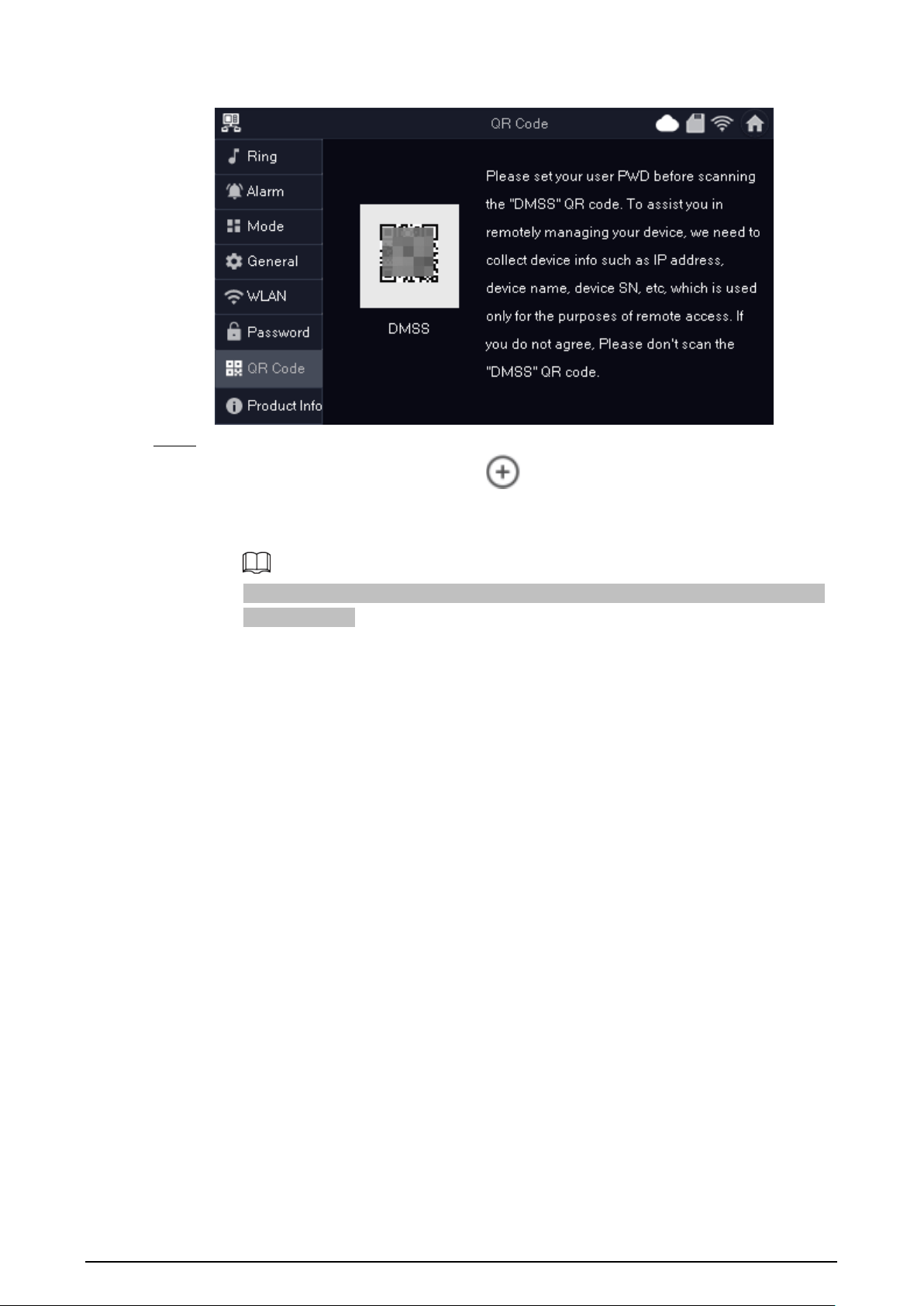
6.5.5 WLAN
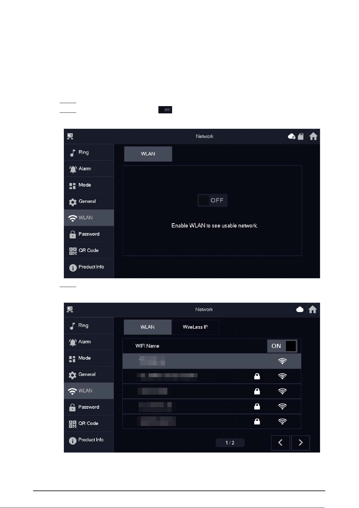
6.5.5.1 WLAN Configuration
Procedure
Step 1 On the main screen, select
Setting
>
WLAN
.
Step 2 Tap
WLAN
screen, and tap to see all of the available Wi-Fi services.
Figure 6-26 Enable Wi-Fi
Step 3 Tap a Wi-Fi, and then enter the password to connect to the Wi-Fi.
Figure 6-27 Wi-Fi list

43
6.5.5.2 Wireless IP
Procedure
Step 1 On the main screen, select
Setting
>
WLAN
.
Step 2 Tap
Wireless IP
, and enter
Local IP
,
Subnet Mask
and
Gateway
, and then tap
OK
.
You can also tap
Wireless IP
, and turn on
DHCP
to obtain the information automatically.
Figure 6-28 Wireless IP
6.5.6 Password Management
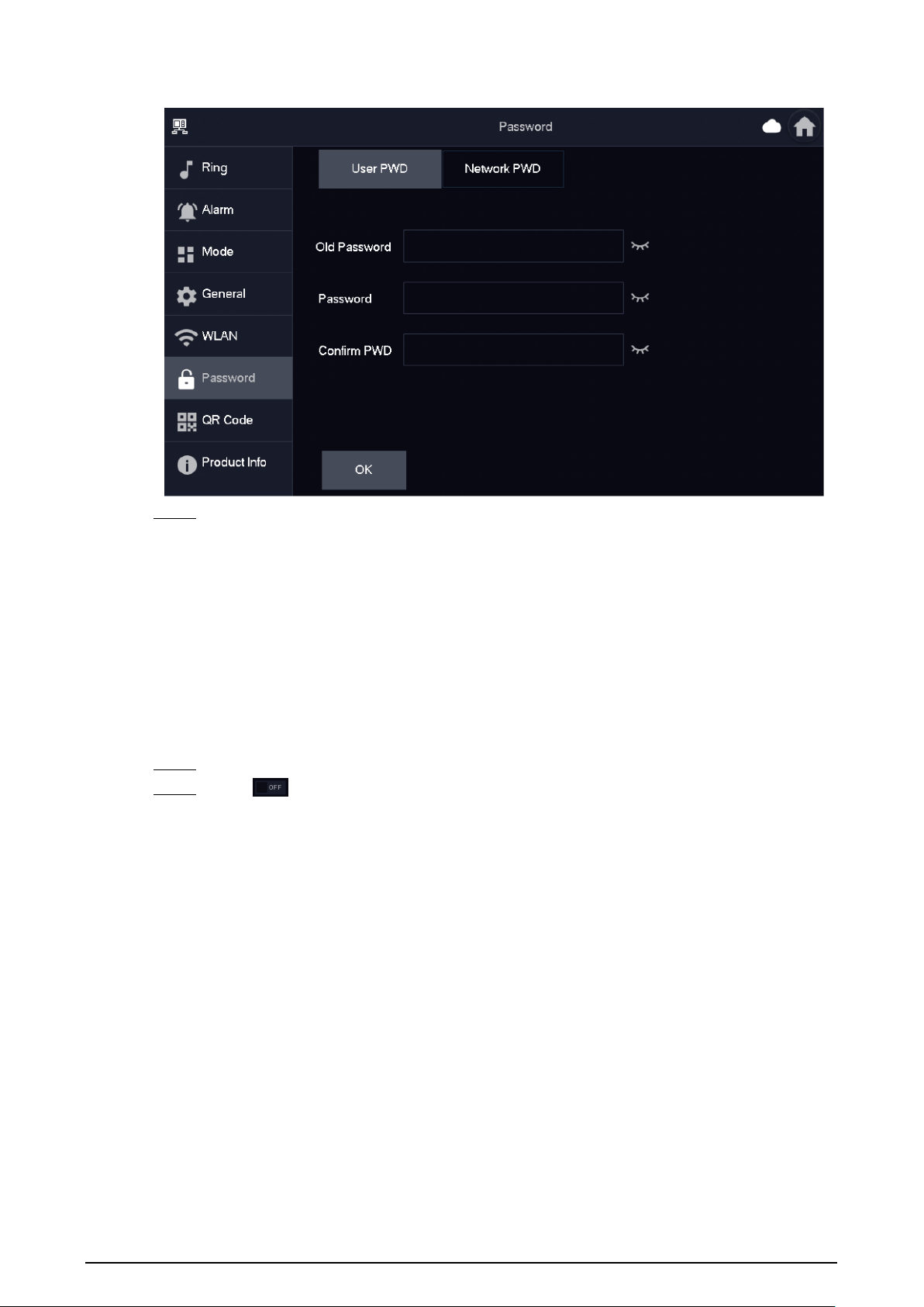
6.5.6.1 User Password
The user password is used to enter the arm and disarm mode. You can revise your user password
based on your needs. The default password is 123456.
Procedure
Step 1 On the home screen, select
Setting
>
Password
>
User PWD
.
Step 2 Enter the old password, new password and conform it.
44
Figure 6-29 Change user password
Step 3 Tap
OK
to save the configuration.
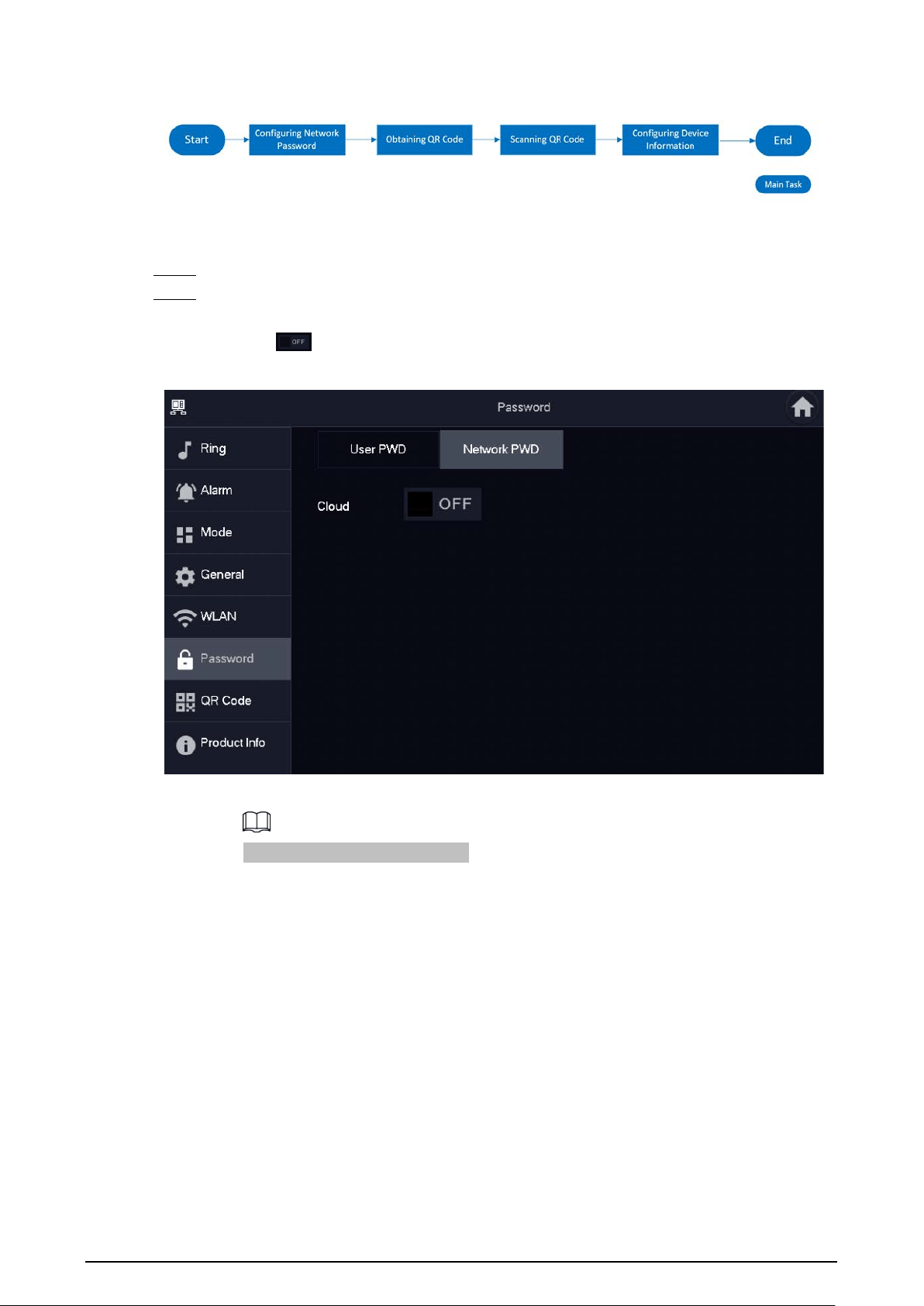
6.5.6.2 Network Password
The network password is used when adding the VTH to the DMSS app.
6.5.6.2.1 Creating Network Password
The network password is used to add the VTH to the DMSS app.
Procedure
Step 1 On the home screen, select
Setting
>
Password
>
Network PWD
.
Step 2 Tap to enable the cloud function.

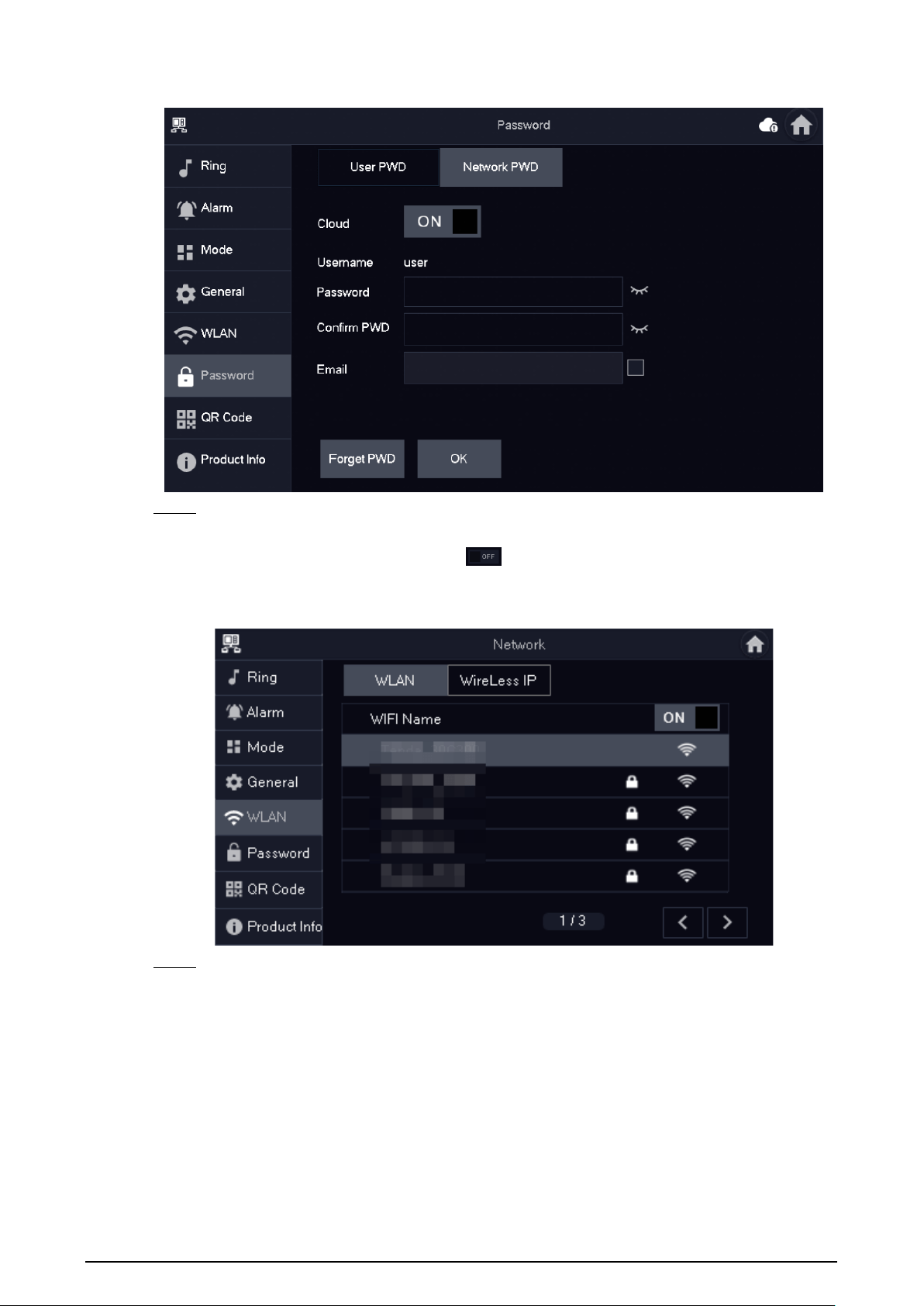
45
Figure 6-30 Enable cloud
Step 3 Create a user account and then enter the password you planned and then confirm it.
The
Username
is
user
by default.
Figure 6-31 Create network password
Step 4 Tap
OK
.
Result
The VTH would automatically generate a QR code that contains the
User
account. When you scan
the DMSS QR code in the
Setting
>
QR Code
, the DMSS App would synchronize the device
information of the VTH.

46
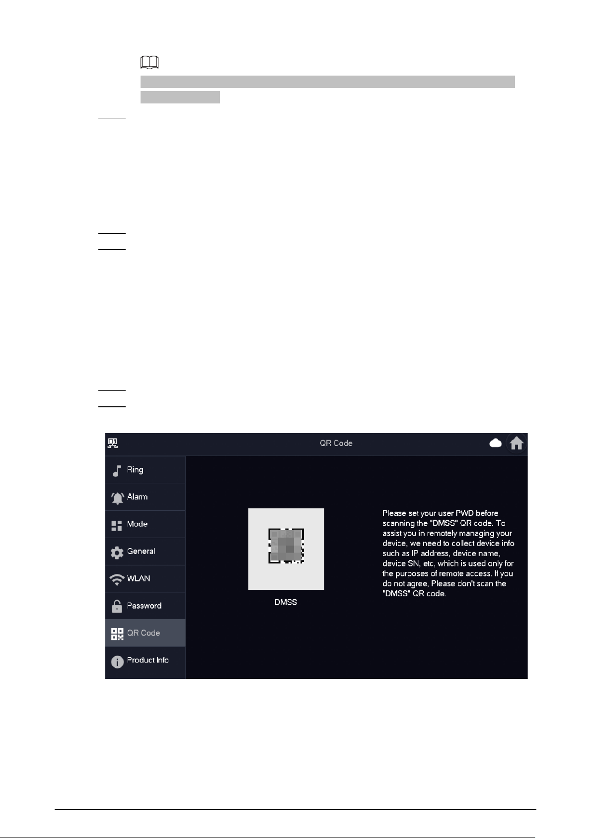
When going to the QR Code screen for the first time, the
DMSS
QR code would not appear. Only
after you set the network password, this module would be displayed.
Figure 6-32 DMSS QR code
6.5.6.2.2 Modifying Network Password
This section applies to the situation when you know your current network password and you want to
change it to another one.
Procedure
Step 1 On the home screen, select
Setting
>
Password
>
Network PWD
.
Step 2 Enter the old password, new password and then confirm the new one.
Figure 6-33 Change password
47
Make sure that you have created a strong password. Otherwise, there will be onscreen
prompt appeared.
Step 3 Tap
OK
.
6.5.6.2.3 Resetting Network Password
This section applies to the situation when you forget your network password and you can reset it to
create a new one.
Procedure
Step 1 On the home screen, select
Setting
>
Password
>
Network PWD
.
Step 2 Tap
Forget PWD
, and enter the new password in the
Password Verification
window, and
then tap
OK
.
6.5.7 QR Code
Scan the QR code using your DMSS App so you can obtain the device information, such as SN, IP
address of VTH.
Procedure
Step 1 Tap
Setting
.
Step 2 Select
QR Code
.
Figure 6-34 QR code
48
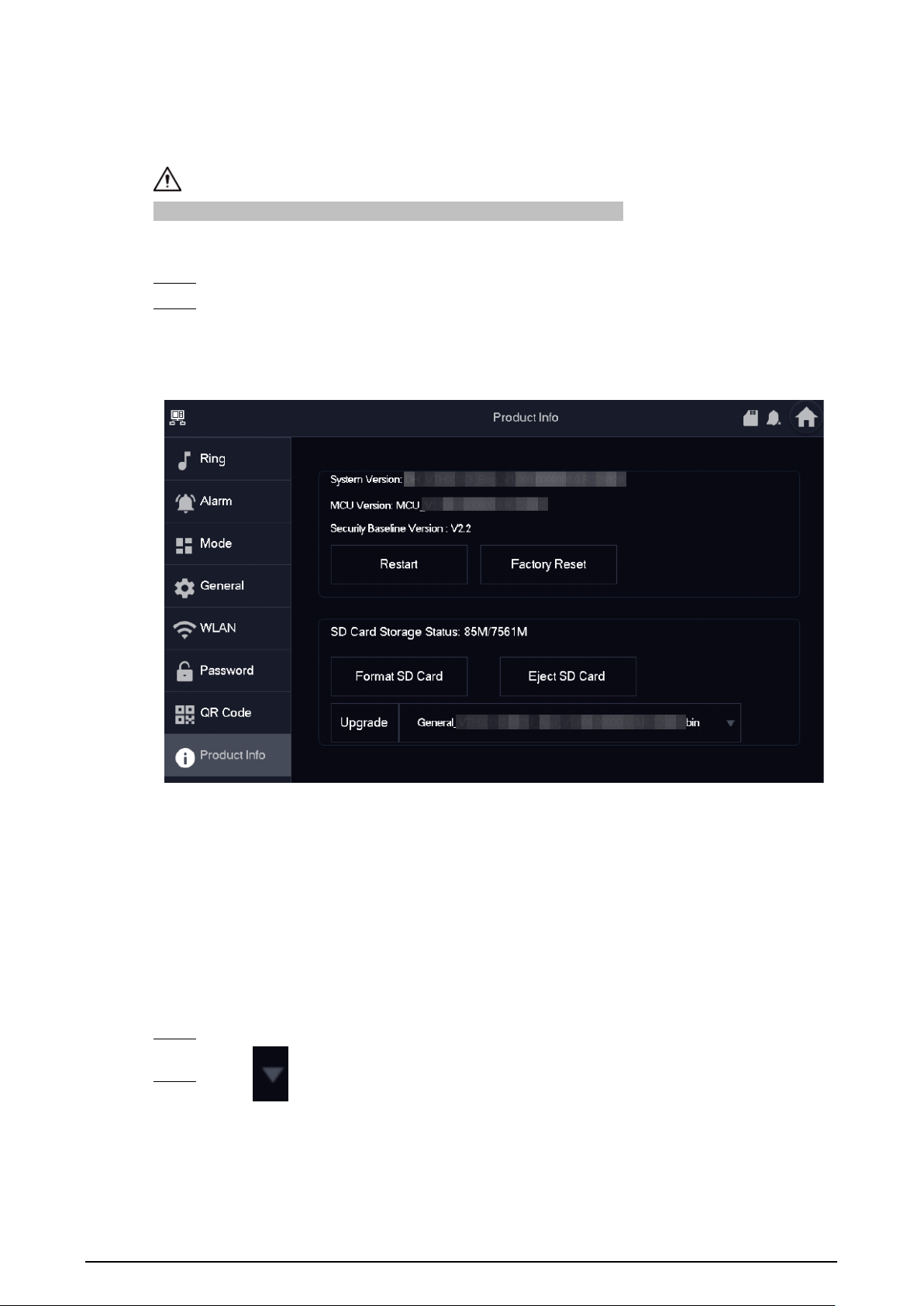
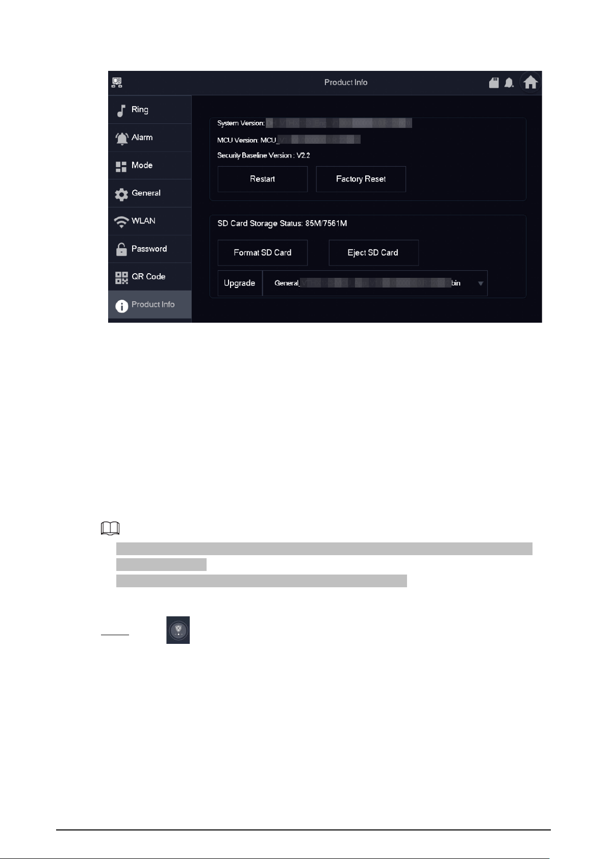
6.5.8 Product Information
Restart the system and format SD card.
If SD card is not inserted into the device, SD format function is invalid.
Procedure
Step 1 Tap
Setting
.
Step 2 Select
Product Info
.
●
Restart
: Restart the device.
●
Factory Reset
: Reset the device to factory setting.
Figure 6-35 Upgrading the device
6.5.9 Upgrading the Program
Prerequisites
●
Make sure that you have uploaded the software for upgrading under the
Upgrade
directory of
the SD card.
●
Make sure that you have inserted the SD card into the VTH.
Procedure
Step 1 Select
Setting
>
Product Info
.
Step 2 Tap to select the upgrading program, and then tap
Upgrade
to upgrade the
software.
49
Figure 6-36 Upgrade the device
Related Operations
●
Format SD Card
: Tap the icon to format the data stored in the SD card.
●
Eject SD Card
: Tap the icon to eject the SD card that inserted in the VTH.
6.6 Arming and Disarming
6.6.1 Arming
In case of triggering alarm after arm, produce linkage alarm and upload alarm information.
●
Please ensure that the area has been added into arm mode. Otherwise, there will be no alarm
triggering after arm.
●
Please ensure that it is in disarmed status. Otherwise, arm will fail.
Procedure
Step 1 Tap on the home screen to view all the arm modes.
●
Home
: Arm the system when inside the area of the alarm system.
●
Away
: Arm the system when you leave the area of the alarm system.
●
Sleep
: An alarming mode that allows you to arm the system in the sleep time.
●
Custom
: Arm the system based on your customized needs.

50
Figure 6-37 Arm mode
Step 2 Enter arm password in the
In Mode Arm
, and then tap
OK
.
●
Default password of arm is 123456. If you want to modify the password, please refer to
"6.5.6.1 User Password" for details.
●
If delay alarm is set in the area, the device will beep continuously at the end of exit
delay time.
6.6.2 Disarming
Procedure
Step 1 In the arm mode, tap .
52
7 DMSS App
7.1 Downloading DMSS App
You can download the DMSS App in the APP Store (iOS) or Google Play (Android) by searching for
DMSS
.
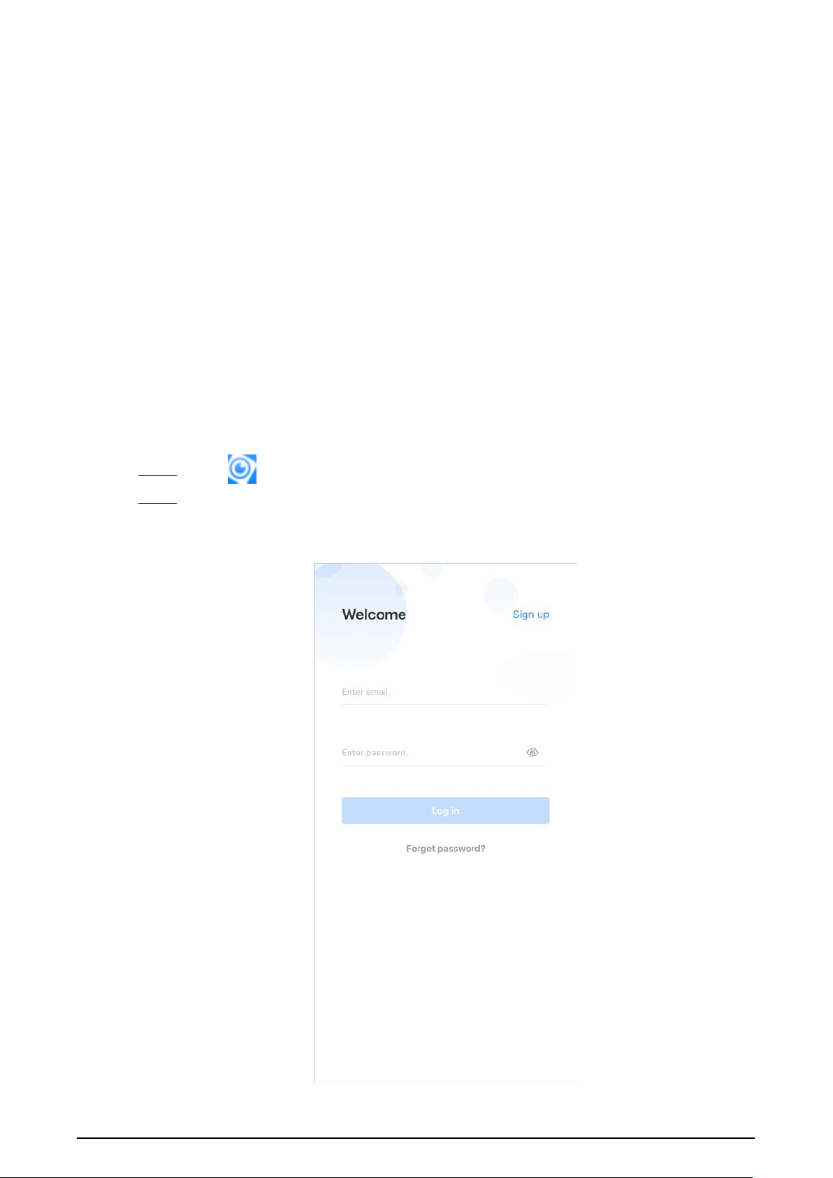
7.2 Registration and Login
For first-time use, you need to create an account. This user manual uses the operations for iOS as an
example
Procedure
Step 1 Tap to start the App.
Step 2 Create an account.
1) On the
Login
screen, tap
Sign up
.
Figure 7-1 Sign up
53
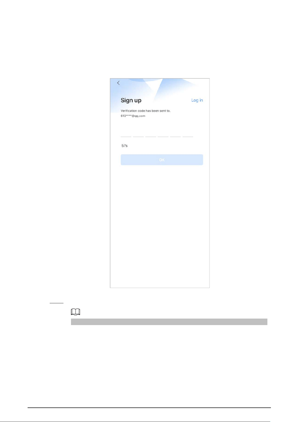
2) Enter your email address and password.
3) Read the
User Agreement and Privacy Policy
, and then select the
I have read and
agree to
checkbox.
4) Tap
Get verification code
, check your email box for the verification code, and then
enter the code.
Figure 7-2 Verification code
5) Tap
OK
.
Step 3 On the
Login
screen, enter your email and password, and then tap
Log in
.
You can modify the password through
Me
>
Account Management
>
Modify Password
.
7.3 Adding VTH to DMSS
Background Information
Before adding VTH to DMSS, see the configuration flow below to help you familiarize the process.
54
Figure 7-3 Configuration flow
Procedure
Step 1 Power on the VTH.
Step 2 Configure network password on the VTH.
1) Select
Setting
>
Password
>
Network PWD
.
2) Tap
to enable the cloud function.
Figure 7-4 Enable Cloud
3) Create a user account, and then enter the password you planned and then confirm it.
The
Username
is
user
by default.
55
Figure 7-5 Create network password
Step 3 Connect to the Wi-Fi.
1) Select
Setting
>
WLAN
.
2) Tap
WLAN
screen, and then tap
to see all of the available Wi-Fi services.
3) Tap a Wi-Fi, and then enter the password to connect to the Wi-Fi.
Figure 7-6 Connect to the Wi-Fi
Step 4 Obtain QR Code. Select
Setting
>
QR Code
to obtain the latest QR code of the VTH, which
contains its device information.
56
Figure 7-7 Obtain DMSS QR code
Step 5 Scan the QR code.
1) On the
Home
screen of the app, tap , and then select
SN/Scan
.
2) Scan the DMSS QR code you obtained in
Setting
>
General
>
QR Code
on the VTH to
obtain the device information of the VTH.
When there is a main VTH and extension(s), make sure that you only scan the QR code
of the main VTH.

57
Figure 7-8 Add VTH
The illustration is for reference only and might differ from the actual one.
Step 6 Configure device information. On the
Add Device
screen, enter the device name of the
VTH, username and password of the VTH, and then tap
Save
.
●
Device Name
: customized.
●
Username
: Enter
user
.
●
Password
: Enter the network password of the VTH you configured in "6.5.6.1 User
Password".
Figure 7-9 Add device
Step 7 Configure the time zone, and then tap
Done
.
58
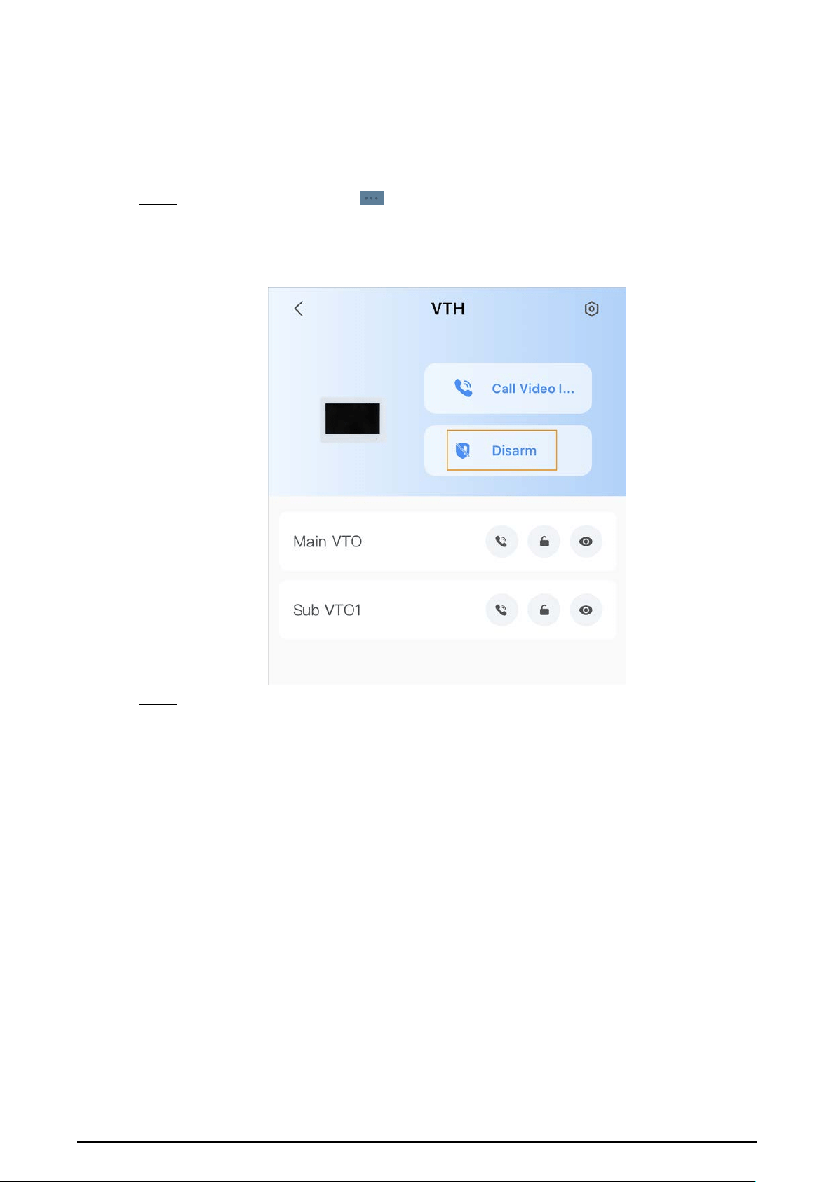
7.4 Configuring Arm and Disarm
Make sure that the VTH and VTO are properly connected.
Procedure
Step 1 On the
Home
screen, tap , select the VTH you have just added, and then tap
Device
Details
to go to the function screen.
Step 2 Tap
Disarm
or
Arm
to disarm or arm the VTH.
Figure 7-10 Disarm VTO
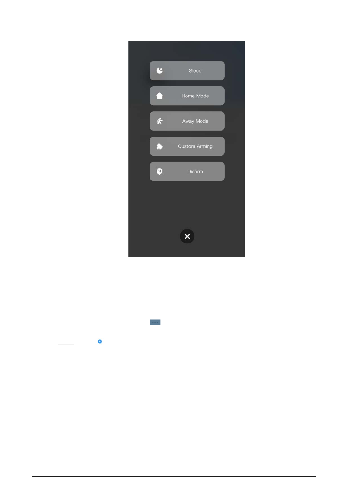
Step 3 Select from the arm/disarm mode list, and the arm/disarm configuration would take effect
on the VTH after you completed the setting.
●
Sleep
: Arm the system in the sleep time.
●
Home Mode
: Arm the system when inside the area of the alarm system.
●
Away Mode
: Arm the system when you leave the area of the alarm system.
●
Custom Arming
: Arm the system based on your customized needs.
●
Disarm
: Turn the security system off. The opposite of arming.
59
Figure 7-11 Arm and disarm mode
7.5 DMSS Monitoring VTO
Make sure that the VTH and VTO are properly connected.
Procedure
Step 1 On the
Home
screen, tap , select the VTH you have added, and then tap
Device
Details
to go to the function screen.
Step 2 Tap
to view the monitoring video of the VTO.

60
Figure 7-12 View monitoring video
Figure 7-13 Viewing monitoring video
Table 7-1 Video call function icons
Function Description
Play/Pause.
61
Function Description
Mute/Unmute.
Change the image orientation to landscape.
Favorites.
Select a video, tap
, and then select an existing file that you want to
save the video to.
Video stream. Tap the icon to switch between SD and HD video quality.
Video playback.
Take snapshot.
Video recording.
Answer/End the call.
7.6 DMSS Calling VTO
Procedure
Step 1 On the
Home
screen, tap , select the VTH you have just added, and then tap
Device
Details
to go to the function screen.
Step 2 Tap
to call the VTO you added to the DMSS.
If there are more than one VTO, you can call the main VTO and sub VTO respectively.
Figure 7-14 Call VTO

62
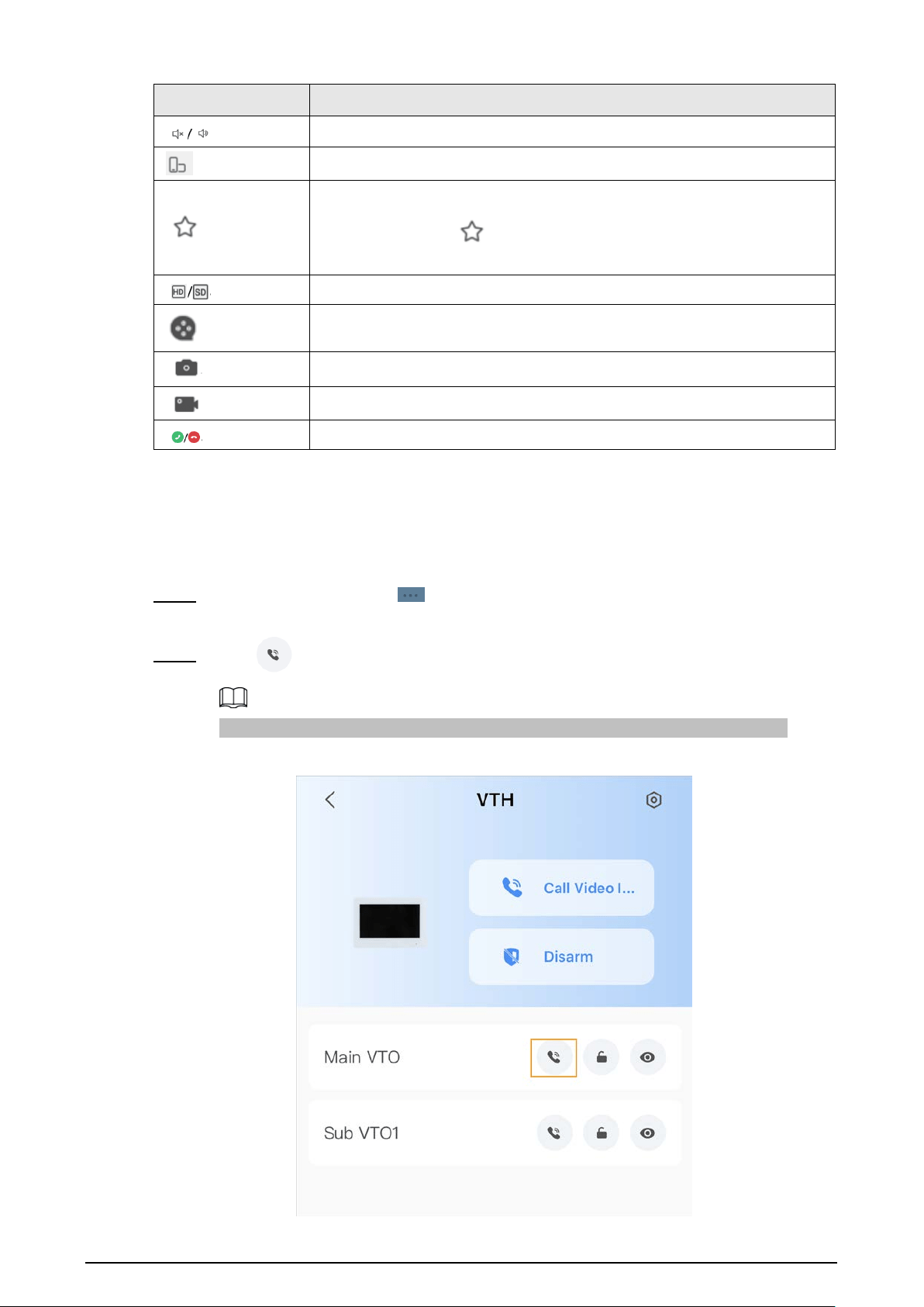
7.7 DMSS Calling VTH
Make sure that the VTH and VTO are properly connected.
Procedure
Step 1 On the
Home
screen, tap , select the VTH you have just added, and then tap
Device
Details
to go to the function screen.
Step 2 Tap
Call Video Intercom
to call the VTH you added to the DMSS.
Figure 7-15 Call VTH
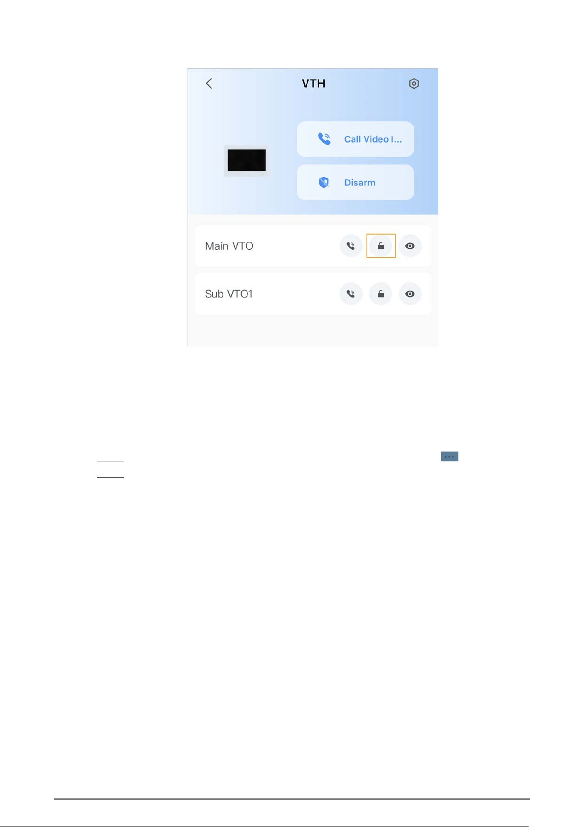
7.8 DMSS Unlocking Door
Procedure
Step 1 On the
Home
screen, tap , select the VTH you have just added, and then tap
Device
Details
to go to the function screen.
Step 2 Tap
to unlock the door.
63
Figure 7-16 Unlock the door
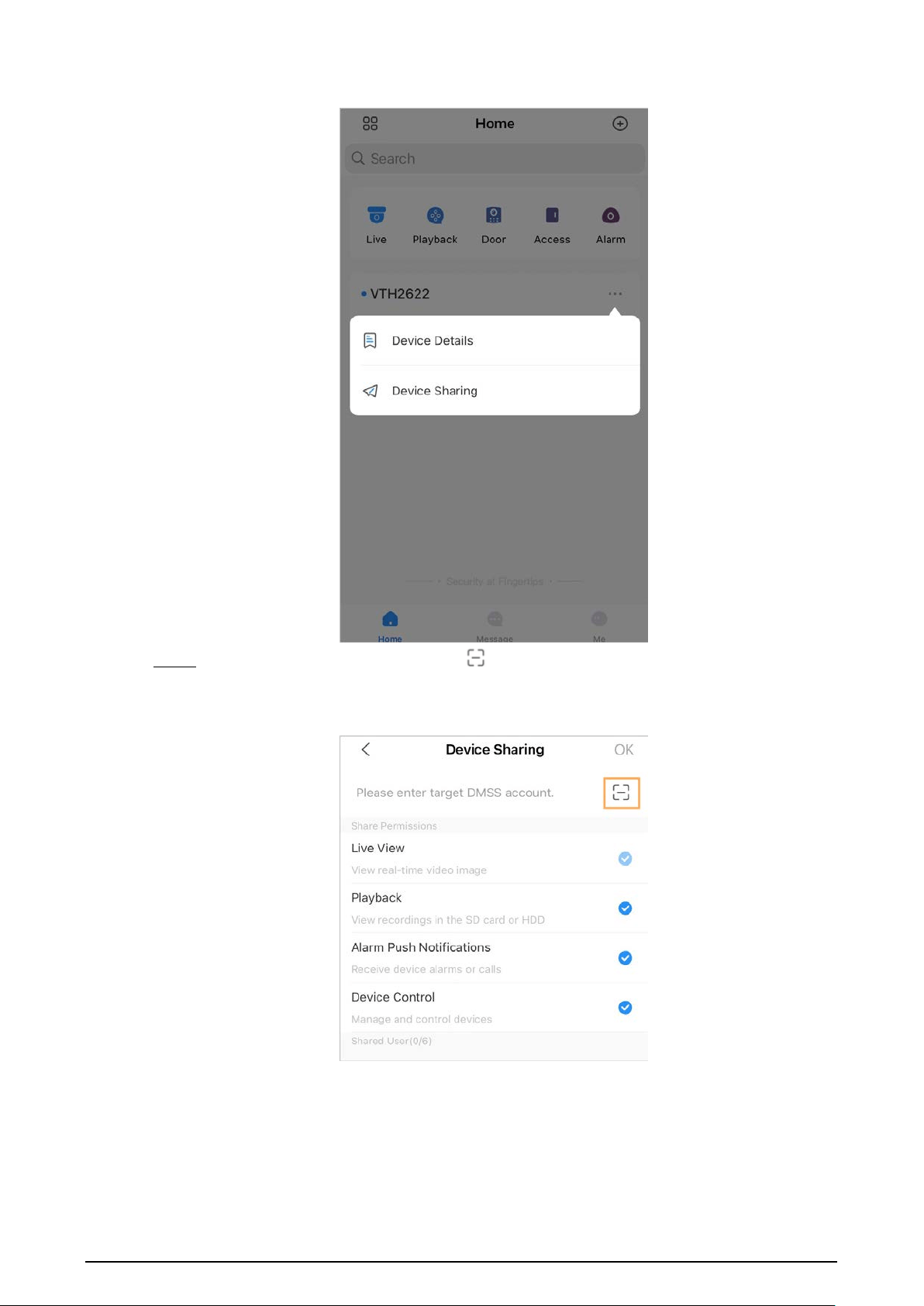
7.9 Device Sharing
Once one user has added the VTH, the user can share the binding relationship with other users.
Procedure
Step 1 On the
Home
screen, select the VTH you have just added, and tap the .
Step 2 Select
Device Sharing
.
64
Figure 7-17 Device sharing (1)
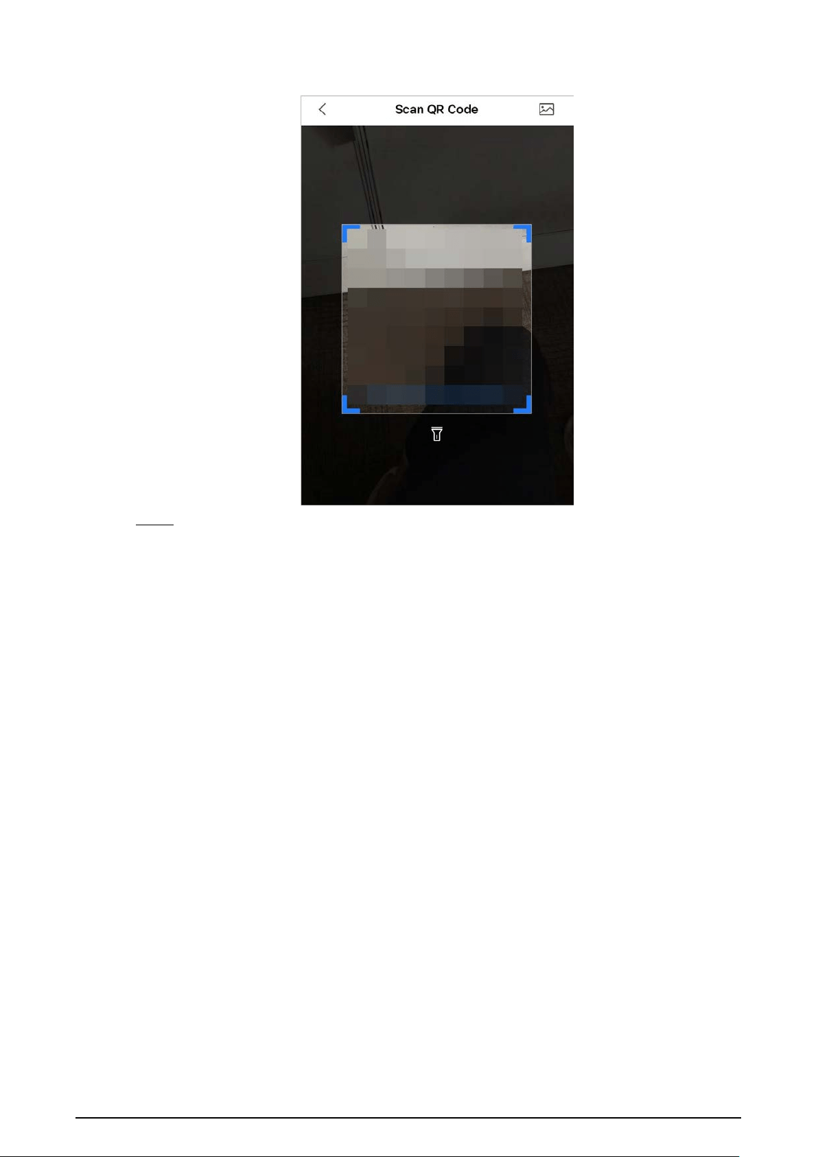
Step 3 On the
Device Sharing
screen, tap
to scan the QR code of the users you want to
share the device.
Figure 7-18 Device sharing (2)
65
Figure 7-19 Scan QR code of the user you want to share
Step 4 After scanning the QR code, the user that receives the sharing has to refresh the
Home
screen to update the sharing information. Otherwise, the shared device information would
be not synchronized automatically.
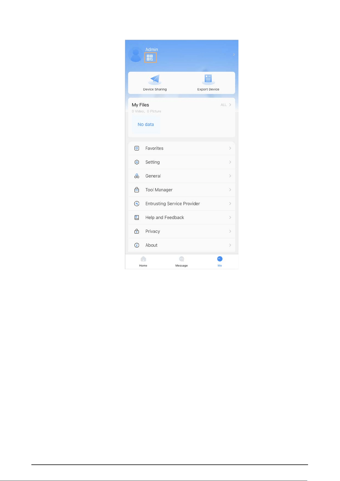
Related Operations
To obtain the QR code of the user that receives the sharing
1. Log in to the DMSS account of the user that to receive the sharing.
2. Tap
Me
, and tap the QR code icon at the top of the screen.
66
Figure 7-20 Obtain the QR code

67
Figure 7-21 Obtain the QR code (2)

68
Appendix 1 Cybersecurity Recommendations
Mandatory actions to be taken for basic equipment network security:
1.
Use Strong Passwords
Please refer to the following suggestions to set passwords:
●
The length should not be less than 8 characters.
●
Include at least two types of characters; character types include upper and lower case letters,
numbers and symbols.
●
Do not contain the account name or the account name in reverse order.
●
Do not use continuous characters, such as 123, abc, etc.
●
Do not use overlapped characters, such as 111, aaa, etc.
2.
Update Firmware and Client Software in Time
●
According to the standard procedure in Tech-industry, we recommend to keep your
equipment (such as NVR, DVR, IP camera, etc.) firmware up-to-date to ensure the system is
equipped with the latest security patches and fixes. When the equipment is connected to the
public network, it is recommended to enable the“auto-check for updates” function to obtain
timely information of firmware updates released by the manufacturer.
●
We suggest that you download and use the latest version of client software.
"Nice to have" recommendations to improve your equipment network security:
1.
Physical Protection
We suggest that you perform physical protection to equipment, especially storage devices. For
example, place the equipment in a special computer room and cabinet, and implement
well-done access control permission and key management to prevent unauthorized personnel
from carrying out physical contacts such as damaging hardware, unauthorized connection of
removable equipment (such as USB flash disk, serial port), etc.
2.
Change Passwords Regularly
We suggest that you change passwords regularly to reduce the risk of being guessed or cracked.
3.
Set and Update Passwords Reset Information Timely
The device supports password reset function. Please set up related information for password
reset in time, including the end user’s mailbox and password protection questions. If the
information changes, please modify it in time. When setting password protection questions, it is
suggested not to use those that can be easily guessed.
4.
Enable Account Lock
The account lock feature is enabled by default, and we recommend you to keep it on to
guarantee the account security. If an attacker attempts to log in with the wrong password several
times, the corresponding account and the source IP address will be locked.
5.
Change Default HTTP and Other Service Ports
We suggest you to change default HTTP and other service ports into any set of numbers between
1024–65535, reducing the risk of outsiders being able to guess which ports you are using.
6.
Enable HTTPS
We suggest you to enable HTTPS, so that you visit Web service through a secure communication
channel.
7.
MAC Address Binding
We recommend you to bind the IP and MAC address of the gateway to the equipment, thus

69
reducing the risk of ARP spoofing.
8.
Assign Accounts and Privileges Reasonably
According to business and management requirements, reasonably add users and assign a
minimum set of permissions to them.
9.
Disable Unnecessary Services and Choose Secure Modes
If not needed, it is recommended to turn off some services such as SNMP, SMTP, UPnP, etc., to
reduce risks.
If necessary, it is highly recommended that you use safe modes, including but not limited to the
following services:
●
SNMP: Choose SNMP v3, and set up strong encryption passwords and authentication
passwords.
●
SMTP: Choose TLS to access mailbox server.
●
FTP: Choose SFTP, and set up strong passwords.
●
AP hotspot: Choose WPA2-PSK encryption mode, and set up strong passwords.
10.
Audio and Video Encrypted Transmission
If your audio and video data contents are very important or sensitive, we recommend that you
use encrypted transmission function, to reduce the risk of audio and video data being stolen
during transmission.
Reminder: encrypted transmission will cause some loss in transmission efficiency.
11.
Secure Auditing
●
Check online users: we suggest that you check online users regularly to see if the device is
logged in without authorization.
●
Check equipment log: By viewing the logs, you can know the IP addresses that were used to
log in to your devices and their key operations.
12.
Network Log
Due to the limited storage capacity of the equipment, the stored log is limited. If you need to
save the log for a long time, it is recommended that you enable the network log function to
ensure that the critical logs are synchronized to the network log server for tracing.
13.
Construct a Safe Network Environment
In order to better ensure the safety of equipment and reduce potential cyber risks, we
recommend:
●
Disable the port mapping function of the router to avoid direct access to the intranet devices
from external network.
●
The network should be partitioned and isolated according to the actual network needs. If
there are no communication requirements between two sub networks, it is suggested to use
VLAN, network GAP and other technologies to partition the network, so as to achieve the
network isolation effect.
●
Establish the 802.1x access authentication system to reduce the risk of unauthorized access to
private networks.
●
Enable IP/MAC address filtering function to limit the range of hosts allowed to access the
device.