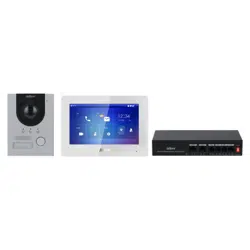
2-Wire Hybrid Door Station
User's Manual
V1.0.0
I
Foreword
General
This manual introduces the structure, functions and networking of the 2-wire hybrid door station
(hereinafter referred to as "the VTO"). Read carefully before using the device, and keep the manual
safe for future reference.
Safety Instructions
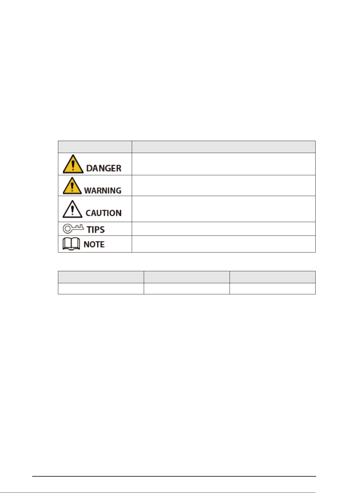
The following signal words might appear in the manual.
Signal Words Meaning
Indicates a high potential hazard which, if not avoided, will result in
death or serious injury.
Indicates a medium or low potential hazard which, if not avoided,
could result in slight or moderate injury.
Indicates a potential risk which, if not avoided, could result in
property damage, data loss, reductions in performance, or
unpredictable results.
Provides methods to help you solve a problem or save time.
Provides additional information as a supplement to the text.
Revision History
Version Revision Content Release Time
V1.0.0 First Release. August 2023
Privacy Protection Notice
As the device user or data controller, you might collect the personal data of others such as their face,
fingerprints, and license plate number. You need to be in compliance with your local privacy
protection laws and regulations to protect the legitimate rights and interests of other people by
implementing measures which include but are not limited: Providing clear and visible identification
to inform people of the existence of the surveillance area and provide required contact information.
About the Manual
●
The manual is for reference only. Slight differences might be found between the manual and the
product.
●
We are not liable for losses incurred due to operating the product in ways that are not in
compliance with the manual.
●
The manual will be updated according to the latest laws and regulations of related jurisdictions.
For detailed information, see the paper user’s manual, use our CD-ROM, scan the QR code or visit
our official website. The manual is for reference only. Slight differences might be found between
the electronic version and the paper version.
●
All designs and software are subject to change without prior written notice. Product updates

II
might result in some differences appearing between the actual product and the manual. Please
contact customer service for the latest program and supplementary documentation.
●
There might be errors in the print or deviations in the description of the functions, operations
and technical data. If there is any doubt or dispute, we reserve the right of final explanation.
●
Upgrade the reader software or try other mainstream reader software if the manual (in PDF
format) cannot be opened.
●
All trademarks, registered trademarks and company names in the manual are properties of their
respective owners.
●
Please visit our website, contact the supplier or customer service if any problems occur while
using the device.
●
If there is any uncertainty or controversy, we reserve the right of final explanation.
III
Important Safeguards and Warnings
This section introduces content covering the proper handling of the device, hazard prevention, and
prevention of property damage. Read carefully before using the device, and comply with the
guidelines when using it.
Operation Requirements
●
Check whether the power supply is correct before use.
●
Do not unplug the power cord on the side of the device while the adapter is powered on.
●
Operate the device within the rated range of power input and output.
●
Transport, use and store the device under allowed humidity and temperature conditions.
●
If the device is powered off for longer than a month, it should be placed in its original package
and sealed. Make sure to keep it away from moisture, and store it under allowed humidity and
temperature conditions.
●
Do not drop or splash liquid onto the device, and make sure that there is no object filled with
liquid on the device to prevent liquid from flowing into it.
●
Do not disassemble the device without professional instruction.
Installation Requirements
●
Do not connect the power adapter to the device while the adapter is powered on.
●
Strictly comply with the local electric safety code and standards. Make sure the ambient voltage
is stable and meets the power supply requirements of the device.
●
Do not connect the device to two or more kinds of power supplies, to avoid damage to the
device.
●
Improper use of the battery might result in a fire or explosion.
●
Personnel working at heights must take all necessary measures to ensure personal safety
including wearing a helmet and safety belts.
●
Do not place the device in a place exposed to sunlight or near heat sources.
●
Keep the device away from dampness, dust, and soot.
●
Install the device on a stable surface to prevent it from falling.
●
Install the device in a well-ventilated place, and do not block its ventilation.
●
Use an adapter or cabinet power supply provided by the manufacturer.
●
Use the power cords that are recommended for the region and conform to the rated power
specifications.
●
The power supply must conform to the requirements of ES1 in IEC 62368-1 standard and be no
higher than PS2. Please note that the power supply requirements are subject to the device label.
●
The device is a class I electrical appliance. Make sure that the power supply of the device is
connected to a power socket with protective earthing.

IV
Table of Contents
Foreword
........................................................................................................................................................................................................I
Important Safeguards and Warnings
............................................................................................................................................ III
1 Product Overview
................................................................................................................................................................................. 1
1.1 Introduction
................................................................................................................................................................................. 1
1.2 Function
......................................................................................................................................................................................... 1
2 Network Diagram
................................................................................................................................................................................. 2
3 Installation
............................................................................................................................................................................................... 9
4 Structure
................................................................................................................................................................................................. 10
4.1 Front Panel
.................................................................................................................................................................................. 10
4.2 Rear Panel
.................................................................................................................................................................................... 12
5 Wiring
....................................................................................................................................................................................................... 14
6 Basic DIP Configuration
.................................................................................................................................................................. 15
6.1 DIP Switch Introduction
....................................................................................................................................................... 15
6.2 Configuring VTO Address
.................................................................................................................................................... 16
7 Software Functions
............................................................................................................................................................................ 19

1
1 Product Overview
1.1 Introduction
The 2-wire hybrid VTO uses the metal front panel and supports featured nameplate. Using two wires
for communication, the VTO supports video intercom with 2-wire hybrid VTH, and supports local
lock and external 485 lock; it also supports call alarm and message notification on DMSS app.
We recommend using the power supply provided with the device in the package. If you solely
purchased the device without its power supply, then please make sure that the power supply you
intend to use was certified by our company.
1.2 Function
2-wire Communication
Supports 2-wire communication.
Video/Voice Call
Make video or voice call to VTHs.
Monitoring
Videos can be monitored by VTH or DMSS app users.
Auto IR Illumination
Supports auto IR illumination at night.
Unlock
Swipe the cards or use the password to open the door.
Card and password function are available on select models.
Keypad with Braille
The device has the keypad with braille.
Keypad with braille is available on select models.

2
2 Network Diagram
The network diagrams below display all the networking scenarios.
Different models of the devices have different requirements.
1. For H series VTH and F series VTO.
When there are 6 devices (VTH+VTO) connected together, only a maximum of 2 devices can
provide power output.
2. For G series VTH and S series VTO.
●
When there are no more than 4 VTHs, the maximum current output of all the 12 VDC power is
500 mA.
●
When there are more than 4 VTHs, the maximum current output of all the 12 VDC power is
300 mA.
●
The power supply of HDCVI camera cannot be grounded.
●
The product appearance is for reference only.
3
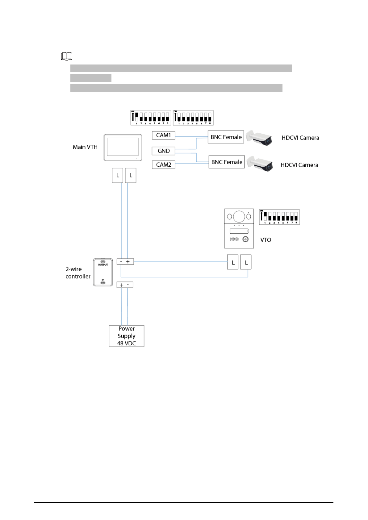
Wiring 1 VTO and 1 VTH
●
The two wires connected to the positive and negative terminals of OUT cannot be
short-circuited.
●
The line termination terminal and branch terminal are optional in this scenario.
Figure 2-1 Network diagram (without line termination terminal and branch terminal)

4
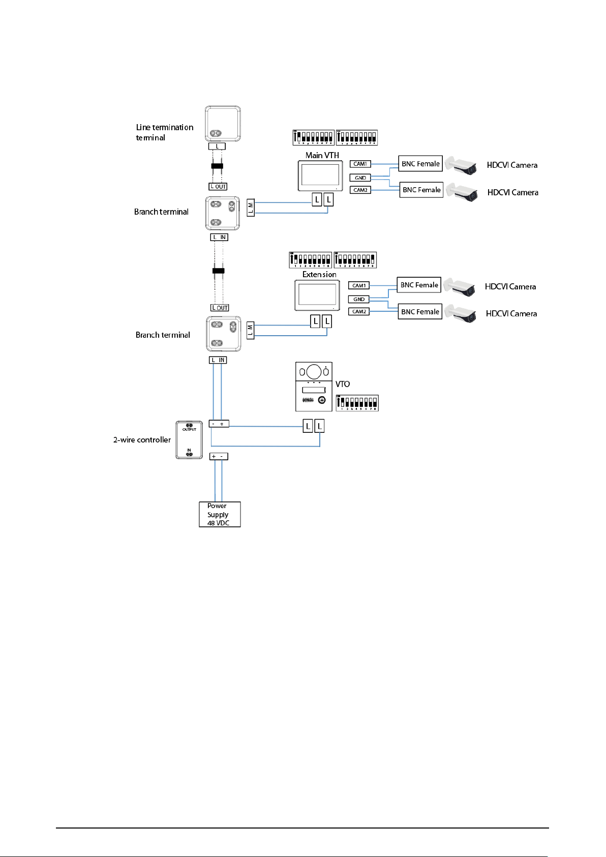
Figure 2-2 Network diagram (with line termination terminal and branch terminal)
Wiring 1 VTO and 2 VTHs (Cascade Connection)
Figure 2-3 Network diagram
5
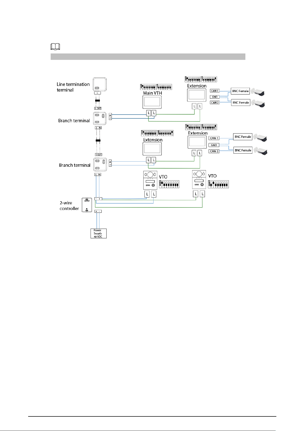
Wiring 1 VTO and 2 VTHs (Parallel Connection)
Figure 2-4 Network diagram
6
Wiring 2 VTOs and 4 VTHs
The DIP number of each VTO cannot be the same. Otherwise, the connection might fail.
Figure 2-5 Network diagram

7
Wiring Distance Between the VTH and VTO
●
It is recommended that the distance between the line termination terminal and the 2-wire
controller do not exceed 3 m.
●
Max distance (A) refers to the distance between the VTH and the VTO.
●
Max distance (B) refers to the distance between the 2-wire controller and the VTH.
Figure 2-6 Max distance
Table 2-1 Wiring distance
RVV Cable AWG
Max.
Distance
(A)
Max.
Distance (B)
Max.
Quantity of
Terminals
2 × 0.5 mm² 20 180 m 100 m 6
2 × 1.5 mm² 15 180 m 100 m 6
RVVP Cable
AWG
Max.
Distance
(A)
Max.
Distance (B)
Max.
Quantity of
Terminals
2 × 0.5 mm² 20 150 m 100 m 6
Network Cable
AWG
Max.
Distance
(A)
Max.
Distance (B)
Max.
Quantity of
Terminals
Cat5e Single Pair 24 100 m 35 m 6
8
Cat5e Single Pair 24 100 m 50 m 4
Multi Pair
Cable
24 200 m 100 m 6
Telephone Wire
AWG
Max.
Distance
(A)
Max.
Distance (B)
Max.
Quantity of
Terminals
Telephone Wire 24 20 m 20 m 2
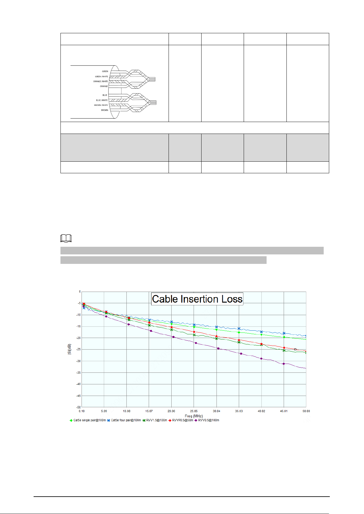
Cable Insertion Loss
Insertion loss refers to the situation of sending a signal from one end of the cable and receiving the
signal at the other end of the cable.
The calculation of cable insertion loss is as follows: Insertion Loss = 20 × Log (signal received/signal
sent)
The cable insertion loss followed is collected from the laboratory environment, and is for reference
only. The actual data might differ from that collected in the test environment.
Figure 2-7 Cable insertion loss

9
3 Installation
●
Do not expose the VTO to condensation, high temperature, direct sunlight, stain, dust, and
chemically corrosive substances.
●
Installation should be done by professional teams. Do not dismantle or repair the VTO by yourself
in case of device failure. Contact after-sales service if you need any help.
●
Prepare cross screwdrivers and gloves yourself.
●
The recommended installation height of the VTO should be no more than 2 m from the ground.
10
4 Structure
4.1 Front Panel
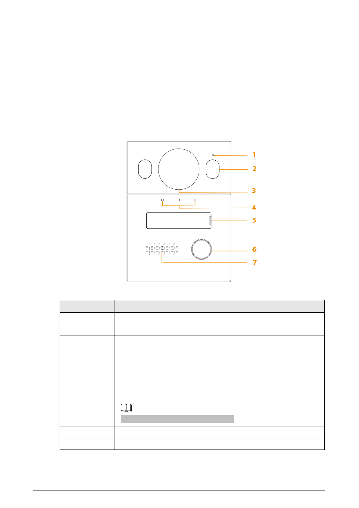
F series model
Figure 4-1 Front panel
Table 4-1 Front panel description
No. Description
1 MIC
2 Illuminator
3 Camera
4
Indicators
●
The left indicator light indicates the call not answered.
●
The middle indicator light indicates the call answered.
●
The right indicator light indicates the door opens.
5
Nameplate
The nameplate is in the accessory package.
6 Call button
7 Speaker
11
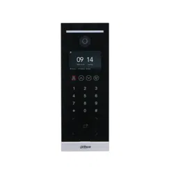
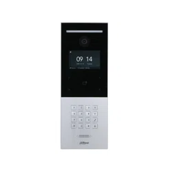
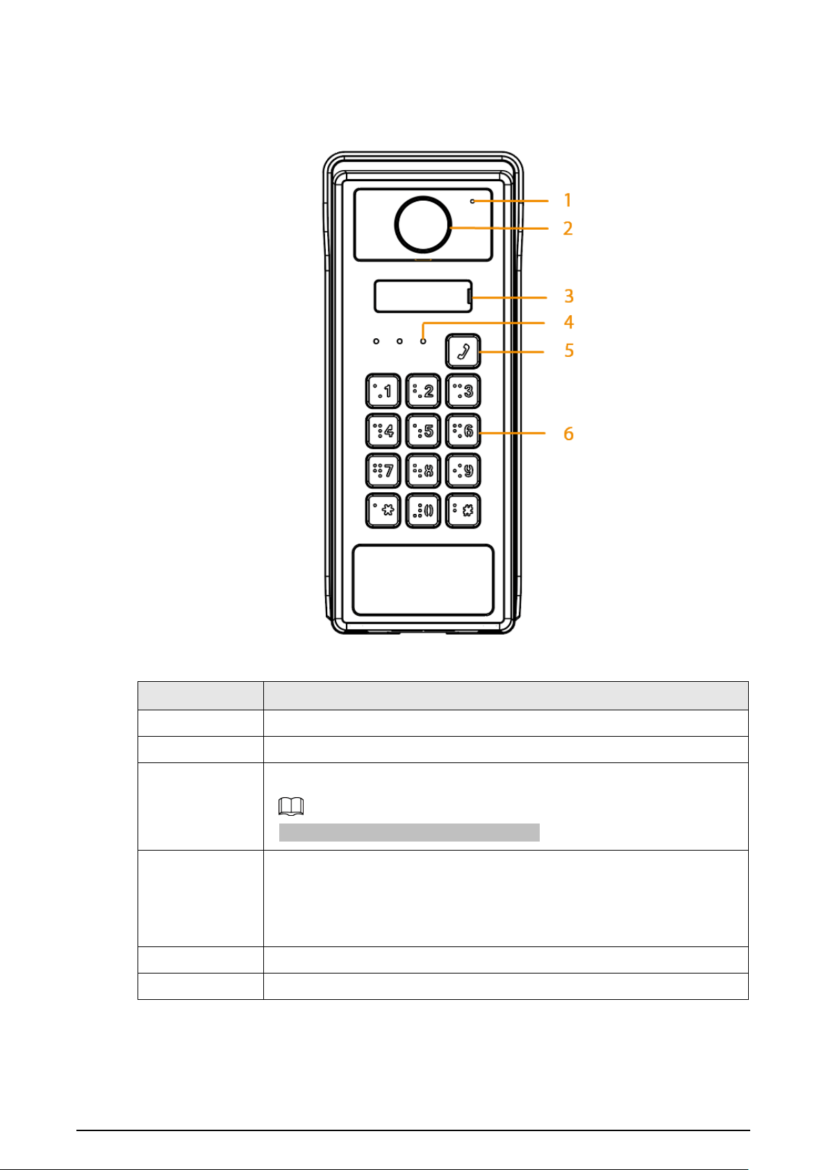
S series model
Figure 4-2 Front panel (S series model)
Table 4-2 Front panel description
No. Description
1 MIC
2 Camera
3
Nameplate
The nameplate is in the accessory package.
4
Indicators
●
The left indicator light indicates the call not answered.
●
The middle indicator light indicates the call answered.
●
The right indicator light indicates the door opens.
5 Call button
6 Keypad

12
4.2 Rear Panel
F series model
Figure 4-3 Rear panel
Table 4-3 Rear panel description
No. Description
1 Tamper button.
2
Volume adjusting button. Use the screwdriver to adjust the volume of the
talk. Rotate the button clockwise to turn down the volume.
3
The upper port is used to upgrade ISP. The lower port is used to upgrade
MCU system.
4 DIP Switch.
5 Door lock port.
6 Power output, RS-485 port and alarm output.
13
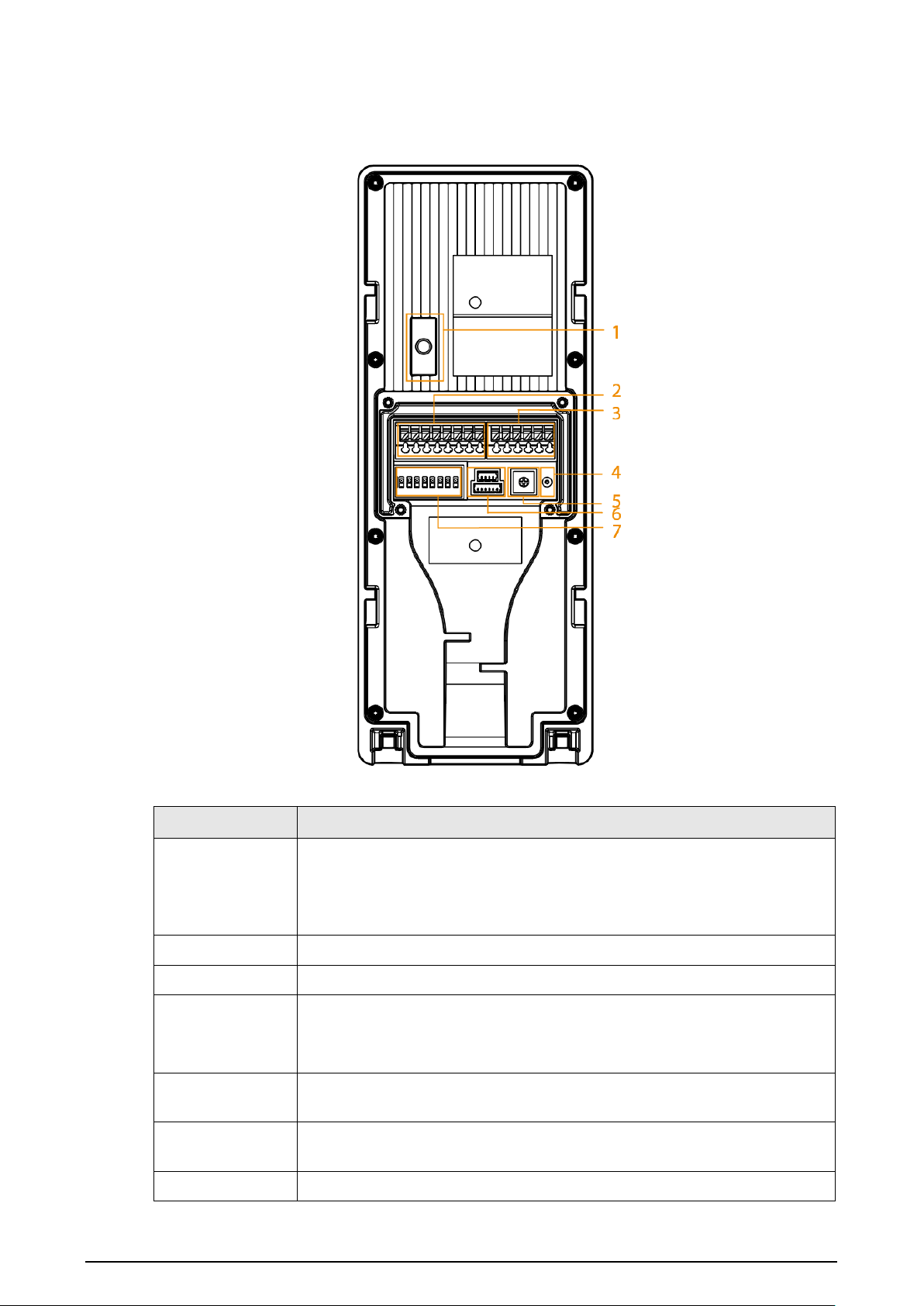
S series model
Figure 4-4 Rear panel
Table 4-4 Rear panel description
No. Description
1
Tamper button.
Within 5 minutes after the device is powered on, if you continuously press
the tamper button for 5 times in 8 seconds, the device beeps and deletes
the admin password.
2 Power output, RS-485 port and alarm output.
3 Door lock port.
4
Reset button.
Press the button for 8 seconds, and the device beeps. The admin password,
card information and opening password will be cleared.
5
Volume adjusting button. Use the screwdriver to adjust the volume of the
talk. Rotate the button clockwise to turn down the volume.
6
The upper port is used to upgrade MCU system. The lower port is used to
upgrade voice programs.
7 DIP switch.
14
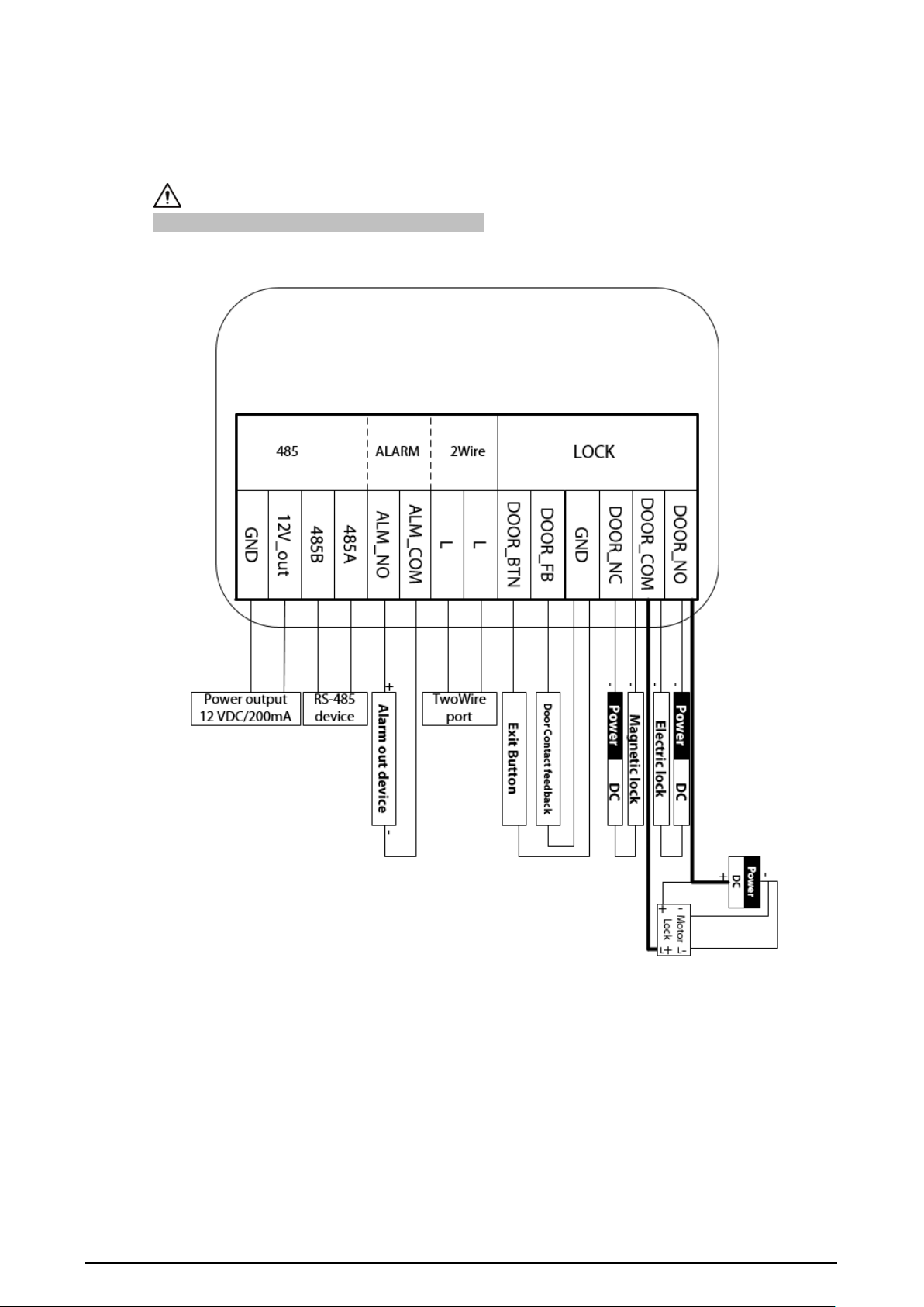
5 Wiring
The alarm input port is connected as dry contact.
Figure 5-1 Wiring
15
6 Basic DIP Configuration
Configure the DIP switches to achieve the function you would like to program, which includes:
●
Configure the address of the VTO.
●
Configure the connection mode.
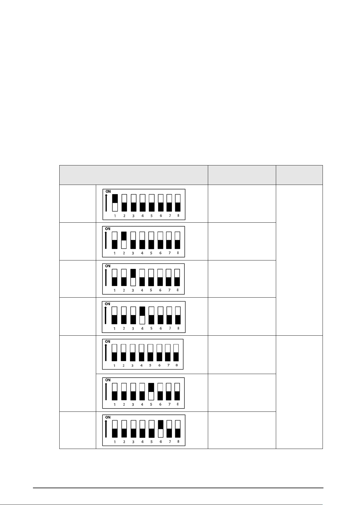
6.1 DIP Switch Introduction
On the Dip-switch, set the code corresponding to the function you want to program as shown in the
table below.
Table 6-1 DIP Switch mapping relations and function
DIP Switch No.
Corresponding
Function
Description
DIP 1
VTO Address 1
Address DIP
configuration.
Supports
programing a
maximum of
14 VTO
addresses.
DIP 2
VTO Address 2
DIP 3
VTO Address 4
DIP 4
VTO Address 8
DIP 5
Lock-release
activation time: 2 Sec
Lock-release
activation
time
Lock-release
activation time: 4 Sec
DIP 6
lock-release activation
time: 6 Sec
16
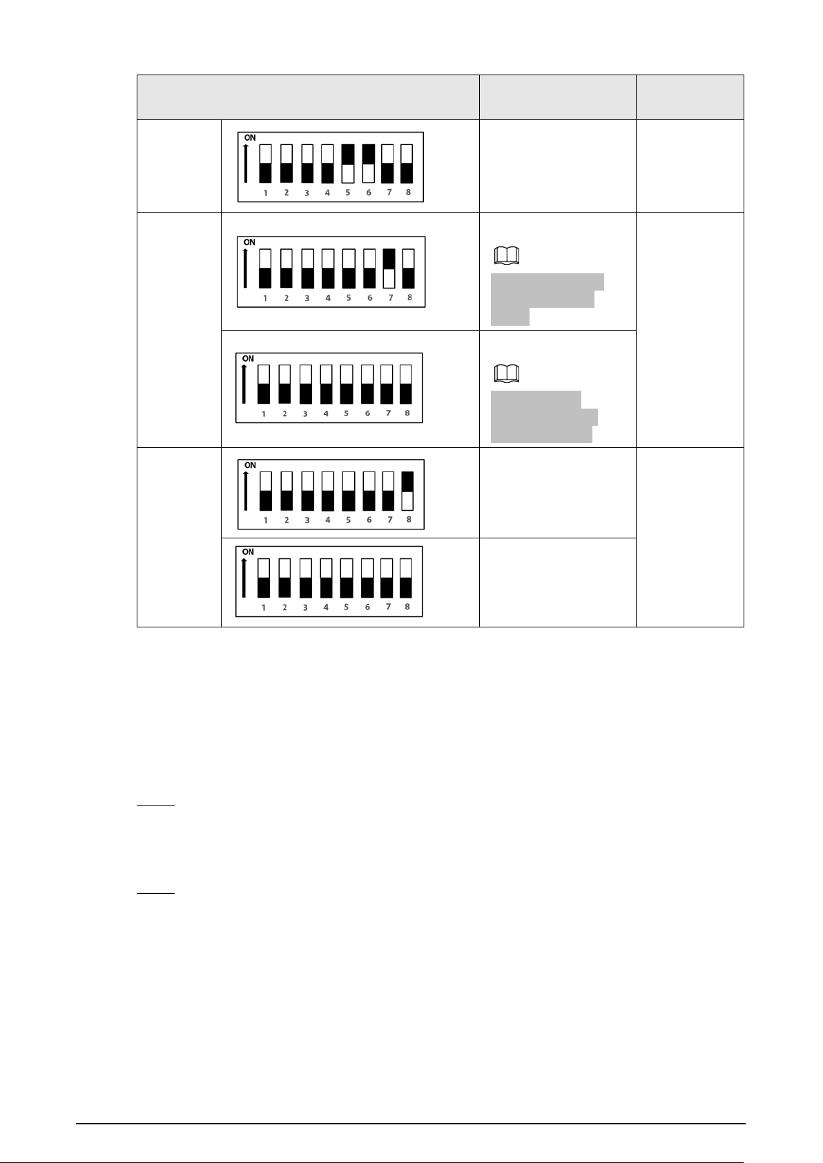
DIP Switch No.
Corresponding
Function
Description
Lock-release
activation time: 8 Sec
DIP 7
ON
: NTSC
Mainly used in the
U.S., Canada and
Japan.
Television
signal coding
system
OFF
: PAL
Mainly used in
Germany, Britain,
China and Spain.
DIP 8
ON
: LED lighting of
nameplate panel
turned on.
LED lighting
of nameplate
panel
OFF
: LED lighting of
nameplate panel
turned off.
6.2 Configuring VTO Address
This section introduces how to configure the address of a VTO through the coding rules of DIP
switches.
Procedure
Step 1 Find the mapping relation between the DIP switch number and the address number you
plan to configure from the table.
It follows a calculation rule that combing only the numbers listed in the
Address No.
only
to form a new address number.
Step 2 Manually move the actuator(s) corresponding to the DIP switch(s) to the status
ON
, so that
the address of the VTO can be configured.
For example, if you want to set your VTO address as 4, you need to first find the mapping
relation (DIP 3 equals to the address number of 4) in the table, and then manually move
the actuator of the DIP 3 to the status
ON
. If you want to set your VTO address as 3, you
need to do the calculation (1+2=3; which equals to the value of DIP1 and DIP 2 combined
together in the mapping relation), and manually move both the actuator of DIP 1 and DIP 2
to the status
ON
.
17
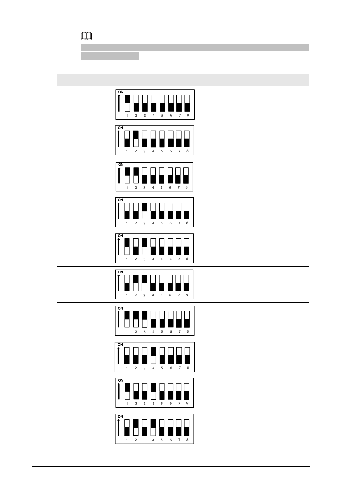
Here is the list of commonly used VTO addresses (1-14) and their corresponding DIP switch
number combinations.
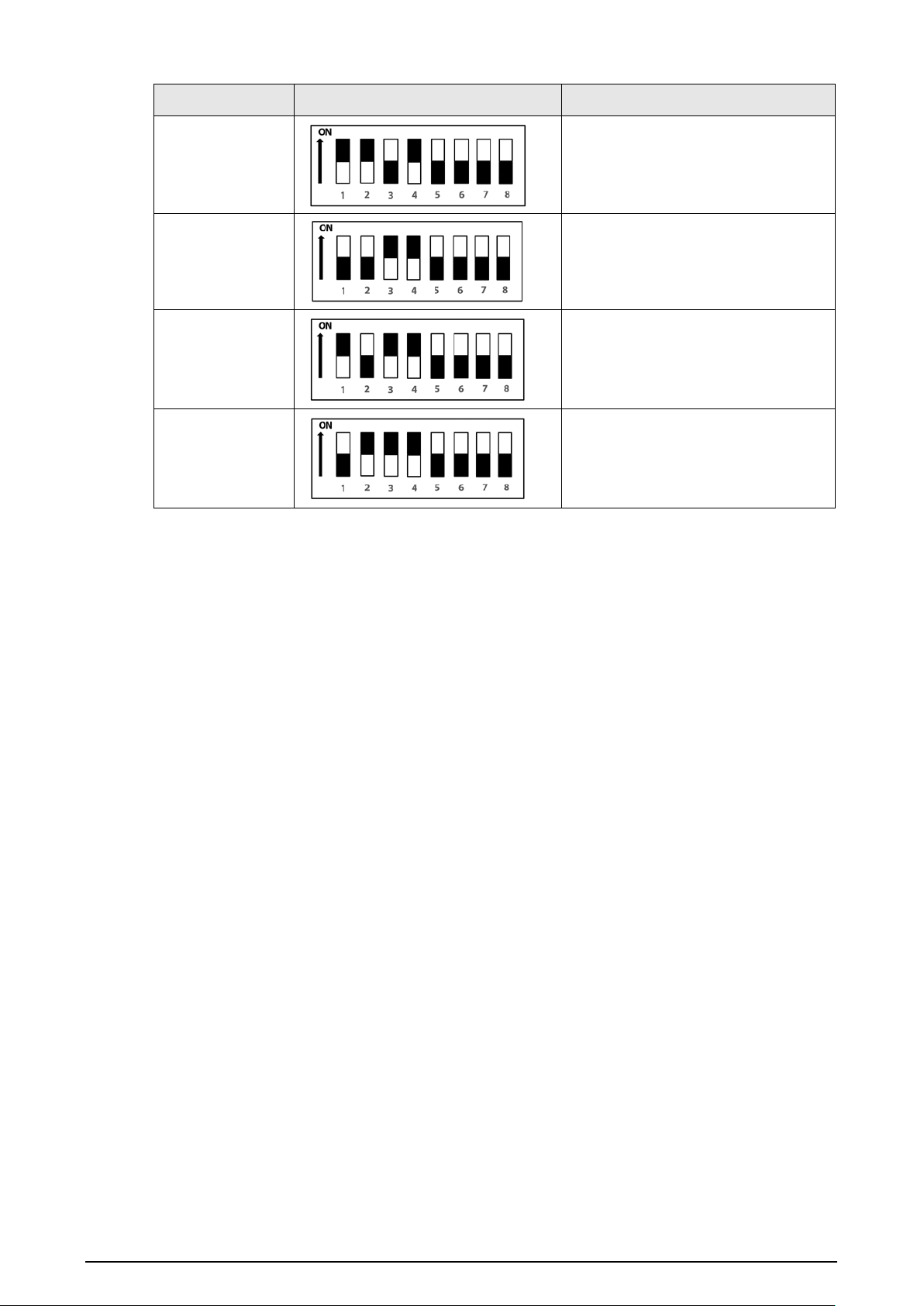
Table 6-2 Common VTO Address (1-14) and DIP switch numbers
VTO Address DIP Switch Combination Coding Rule
1 DIP 1
2
DIP 2
3 DIP 2+ DIP 1
4
DIP 3
5 DIP 3 + DIP 1
6
DIP 2 + DIP 3
7 DIP 3 + DIP 2 + DIP 1
8 DIP 4
9 DIP 4 + DIP 1
10 DIP 4 + DIP 2
18
VTO Address DIP Switch Combination Coding Rule
11
DIP 4 + DIP 2+ DIP 1
12
DIP 4 + DIP 3
13
DIP 4 + DIP 3+ DIP 1
14
DIP 4 + DIP 3+ DIP 2

19
7 Software Functions
Only the S series door station supports the software functions.
●
Press
*
to enter the setting mode. 3 indicators turn red.
●
If the configurations succeed, the indicator light turns blue for 2 seconds and turns off.
●
If the configurations fail, the indicator turns off and the device beeps.
You can add up to 100 different opening passwords and 100 different cards. If you add more than
100 passwords or cards, the device beeps.
Configuring admin password
For first-time use, press
*0*admin password*
to configure the admin password.
●
The password must consist of 4 to 6 numbers.
●
When the admin password is configured successfully, if you press
*0*admin password*
to
configure a new password, the device beeps. The configuration is invalid.
Modifying admin password
Press
*0*original admin password*new admin password*
to modify the admin password.
For example, the original password is 880088, and the new password is 008800. Press
*0*880088*008800*
.
Adding the card
Press
*1*admin password*
, swipe the card, and then press
*
.
If you have not configured the admin password, after pressing
*1
, the device beeps and exits the
setting mode.
Deleting the card
Press
*2*admin password*
to clear the card information.
If you have not configured the admin password, after pressing
*2
, the device beeps and exits the
setting mode.
Adding the opening password
The password is used to open the door.
1. Press
*3*admin password*opening password*
to add a new opening password.
2. Press
#opening password#
to open the door.

20
●
The password must consist of 4 to 6 number.
●
If you have not configured the admin password, after pressing
*3
, the device beeps and exits the
setting mode.
Deleting the opening password
Press
*4*admin password*
to clear the opening password.
If you have not configured the admin password, after pressing
*4
, the device beeps and exits the
setting mode.