
Villa VTO
User’s Manual
V1.0.1
I
Foreword
General
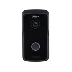
This manual introduces the installation, functions and operations of the villa door station bassline
(hereinafter referred to as "the VTO"). Read carefully before using the device, and keep the manual safe
for future reference.
Safety Instructions
The following categorized signal words with defined meaning might appear in the manual.
Signal Words Meaning
DANGER
Indicates a high potential hazard which, if not avoided, will result in
death or serious injury.
WARNING
Indicates a medium or low potential hazard which, if not avoided,
could result in slight or moderate injury.
CAUTION
Indicates a potential risk which, if not avoided, could result in
property damage, data loss, lower performance, or unpredictable
result.
TIPS
Provides methods to help you solve a problem or save you time.
NOTE
Provides additional information as the emphasis and supplement to
the text.
Revision History
Version Revision Content Release Date
V1.0.1 Revised facade layout description. November 2022
V1.0.0 First release. April 2020
About the Manual
The manual is for reference only. Slight differences might be found between the manual and the
product.
We are not liable for losses incurred due to operating the product in ways that are not in
compliance with the manual.
The manual will be updated according to the latest laws and regulations of related jurisdictions.
For detailed information, see the paper user’s manual, use our CD-ROM, scan the QR code or visit
our official website. The manual is for reference only. Slight differences might be found between
the electronic version and the paper version.
All designs and software are subject to change without prior written notice. Product updates
might result in some differences appearing between the actual product and the manual. Please
contact customer service for the latest program and supplementary documentation.

II
There might be errors in the print or deviations in the description of the functions, operations and
technical data. If there is any doubt or dispute, we reserve the right of final explanation.
Upgrade the reader software or try other mainstream reader software if the manual (in PDF
format) cannot be opened.
All trademarks, registered trademarks and company names in the manual are properties of their
respective owners.
Please visit our website, contact the supplier or customer service if any problems occur while
using the device.
If there is any uncertainty or controversy, we reserve the right of final explanation.
III
Important Safeguards and Warnings
This section introduces content covering the proper handling of the device, hazard prevention, and
prevention of property damage. Read carefully before using the device, and comply with the
guidelines when using it.
Operation Requirements
●
Check whether the power supply is correct before use.
●
Do not unplug the power cord on the side of the device while the adapter is powered on.
●
Operate the device within the rated range of power input and output.
●
Transport, use and store the device under allowed humidity and temperature conditions.
●
Do not drop or splash liquid onto the device, and make sure that there is no object filled with liquid
on the device to prevent liquid from flowing into it.
●
Do not disassemble the device without professional instruction.
Installation Requirements
●
Do not connect the power adapter to the device while the adapter is powered on.
●
Strictly comply with the local electric safety code and standards. Make sure the ambient voltage is
stable and meets the power supply requirements of the device.
●
Do not connect the device to two or more kinds of power supplies, to avoid damage to the device.
●
Improper use of the battery might result in a fire or explosion.
●
Personnel working at heights must take all necessary measures to ensure personal safety including
wearing a helmet and safety belts.
●
Do not place the device in a place exposed to sunlight or near heat sources.
●
Keep the device away from dampness, dust, and soot.
●
Install the device on a stable surface to prevent it from falling.
●
Install the device in a well-ventilated place, and do not block its ventilation.
●
Use an adapter or cabinet power supply provided by the manufacturer.
●
Use the power cords that are recommended for the region and conform to the rated power
specifications.
●
The power supply must conform to the requirements of ES1 in IEC 62368-1 standard and be no
higher than PS2. Please note that the power supply requirements are subject to the device label.
●
The device is a class I electrical appliance. Make sure that the power supply of the device is
connected to a power socket with protective earthing.

IV
Table of Contents
Foreword ............................................................................................................................................................ I
Important Safeguards and Warnings ............................................................................................................. III
1 Initialization ................................................................................................................................................... 1
2 Login Page ..................................................................................................................................................... 2
Login ............................................................................................................................................................................................... 2
Resetting Password ................................................................................................................................................................... 2
3 Home Page ..................................................................................................................................................... 4
4 Local Setting .................................................................................................................................................. 5
Basic ................................................................................................................................................................................................ 5
4.1.1 Device Properties & Events........................................................................................................................................ 5
4.1.2 Facade Layout (Only for VTO3211D) ...................................................................................................................... 6
Video & Audio .............................................................................................................................................................................. 7
Access Control ............................................................................................................................................................................. 8
4.3.1 Local ................................................................................................................................................................................... 9
4.3.2 RS-485 ............................................................................................................................................................................... 9
System .......................................................................................................................................................................................... 10
Security ........................................................................................................................................................................................ 11
Onvif User .................................................................................................................................................................................... 12
5 Household Setting....................................................................................................................................... 13
VTO No. Management ............................................................................................................................................................ 13
5.1.1 Adding VTO ................................................................................................................................................................... 13
5.1.2 Modifying VTO Information .................................................................................................................................... 14
5.1.3 Deleting VTO................................................................................................................................................................. 15
Room No. Management ........................................................................................................................................................ 15
5.2.1 Adding Room Number .............................................................................................................................................. 15
5.2.2 Modifying Room Number ........................................................................................................................................ 17
5.2.3 Issuing Access Card .................................................................................................................................................... 17
VTS Management ..................................................................................................................................................................... 18
Status ............................................................................................................................................................................................ 19
6 Network Setting .......................................................................................................................................... 20
Basic .............................................................................................................................................................................................. 20
6.1.1 TCP/IP .............................................................................................................................................................................. 20
6.1.2 Port ................................................................................................................................................................................... 20
6.1.3 HTTPS .............................................................................................................................................................................. 21
6.1.4 P2P .................................................................................................................................................................................... 21
SIP Server .................................................................................................................................................................................... 21
Firewall ......................................................................................................................................................................................... 22
7 Log Management ........................................................................................................................................ 24
Call ................................................................................................................................................................................................. 24
Alarm ............................................................................................................................................................................................ 24
Unlock .......................................................................................................................................................................................... 24
Log ................................................................................................................................................................................................. 25
Cybersecurity Recommendations ............................................................................................. 26
1
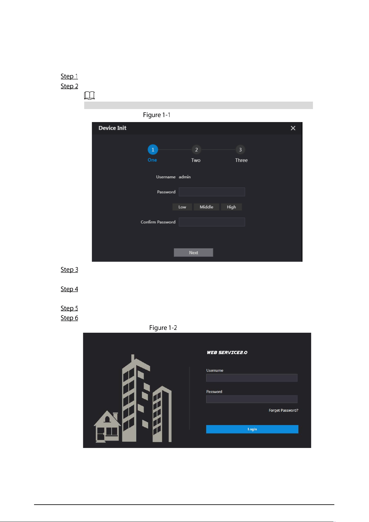
1 Initialization
For first-time login, you need to initialize the VTO.
Power on the VTO.
Go to the default IP address (192.168.1.108) of the VTO, and then press Enter.
Make sure that the IP address of your PC is on the same network segment as the VTO.
Device initialization
Enter and confirm the password, and then click Next.
The email setting interface is displayed.
Select the Email check box, and then enter your email address. This email address can be used
to reset the password.
Click Next. The initialization succeeded.
Click OK.
Login interface
2
2 Login Page
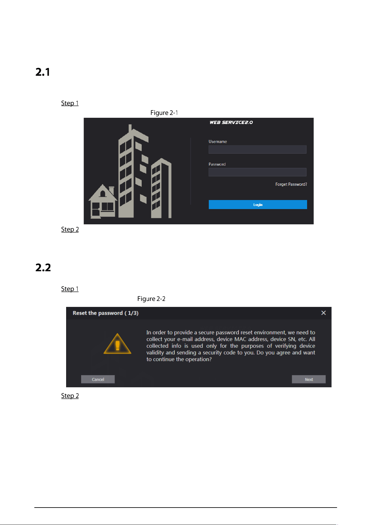
Login
Before login, make sure that the PC and VTO are on the same network segment.
Enter the VTO IP address in the browser address bar, and then press Enter.
Login interface
Enter admin as username, then enter the password you set during initialization, and then click
Login.
Resetting Password
On the login interface (Figure 2-1), click Forgot Password?.
Reset the password (1/3)
Click Next.
3
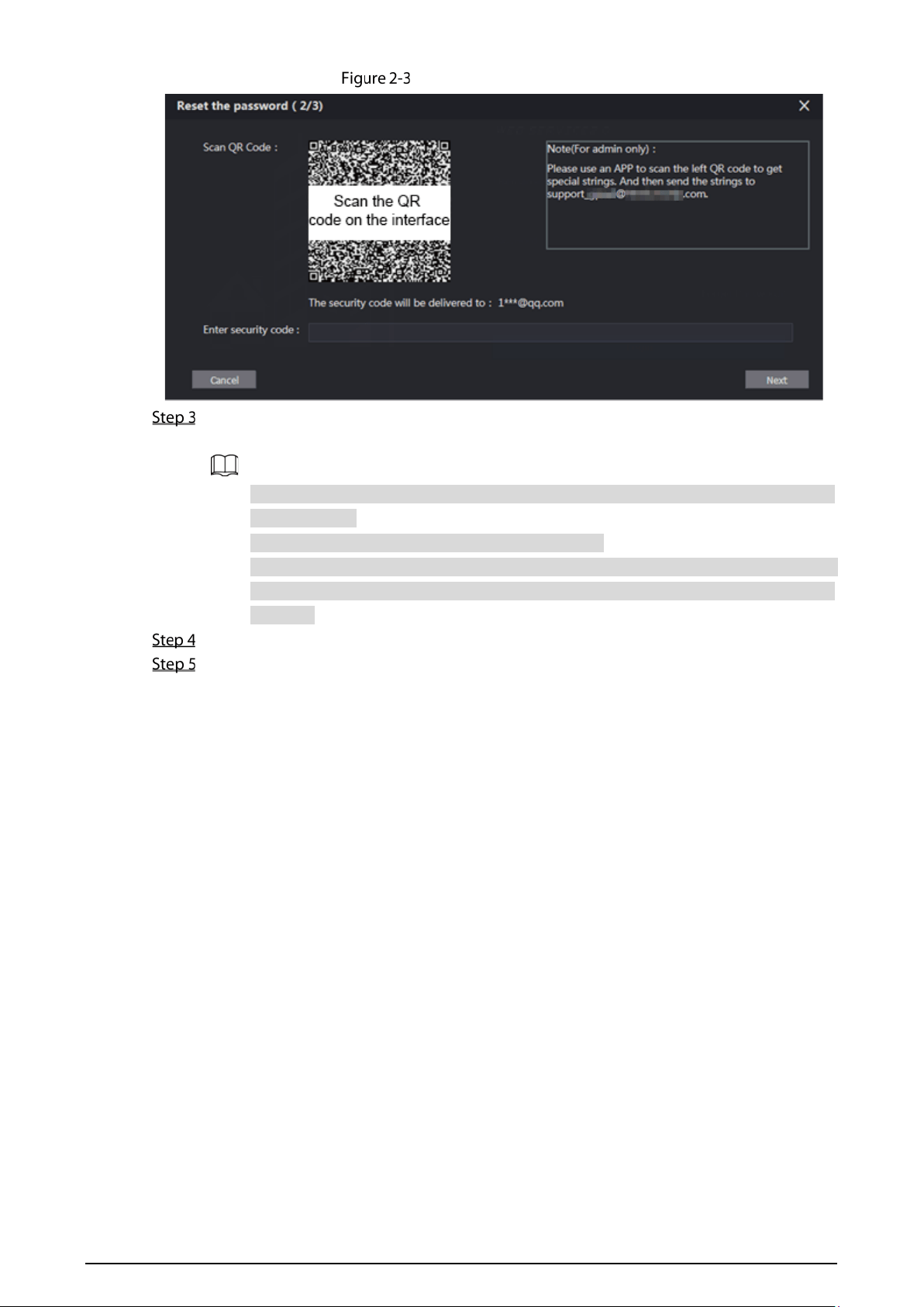
Reset the password (2/3)
Scan the QR code on the web interface to obtain the security code in your mailbox, and then
enter the security code in the input box.
If you did not configure email during initialization, contact the supplier or customer
service for help.
To obtain security code again, refresh QR code page.
Use the security code within 24 hours after receiving it. Otherwise, it will become invalid.
If wrong security code is entered for 5 times continuously, this account will be locked
for 5 min.
Click Next, and then the Reset the password (3/3) dialog box is displayed.
Set and confirm the new password as instructed, and then click OK.
4
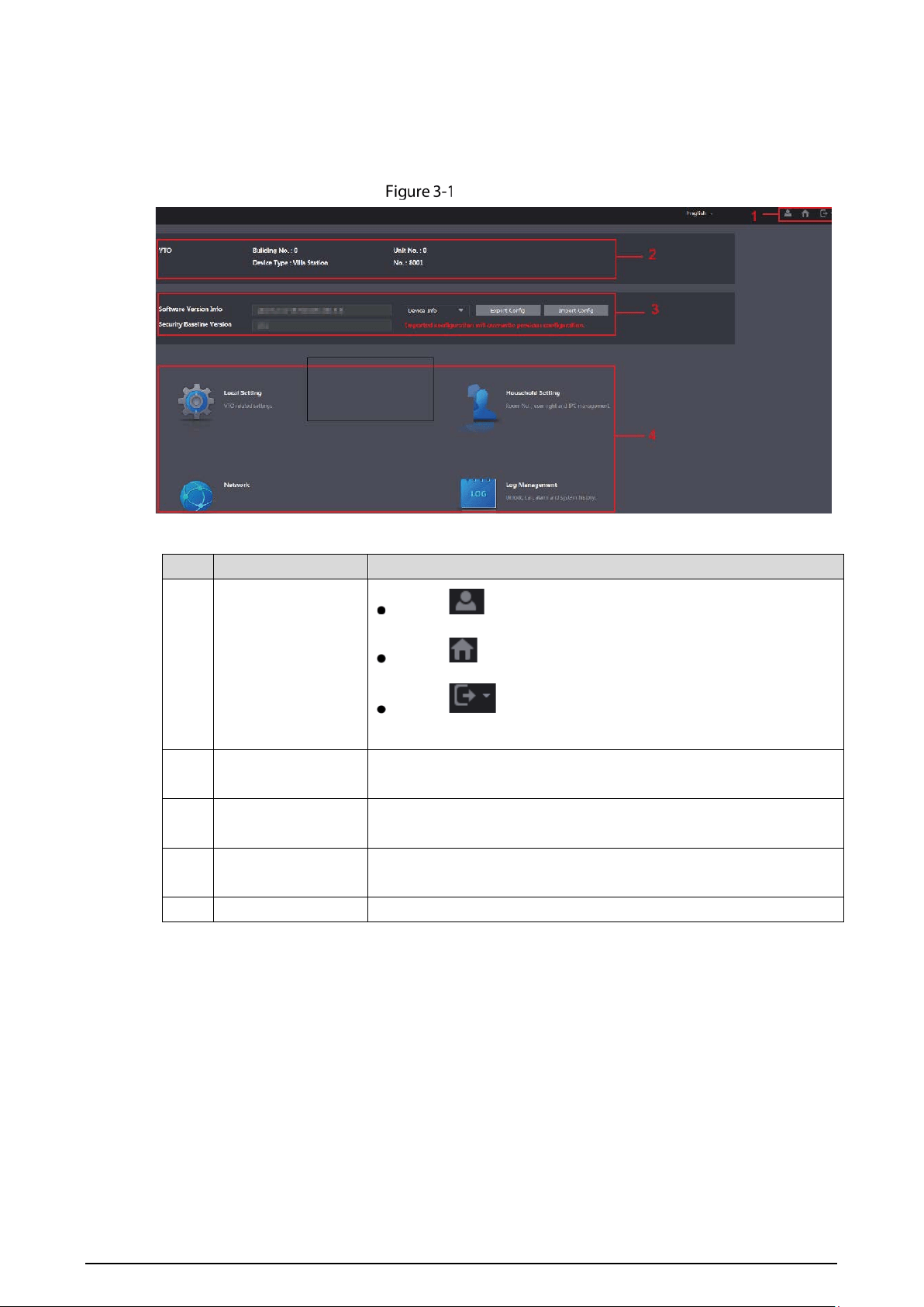
3 Home Page
Log in to the web page of the VTO, and then the home page is displayed.
Home page
Table 3-1 Home page introduction
No. Function Description
1 General function
Click to change the password and your email address.
Click to go to the home page.
Click to log out, reboot the VTO or restore the VTO to
factory settings.
2 VTO information
You can view the general information of the VTO, including building
No., unit No., device type, and VTO No..
3 System information
You can view the software version, MCU version, and security
baseline version.
4 Config manager
Select Device Info or User Info, and then you can export the VTO
configuration or user information to the PC or import them from it.
5 Function area Click the buttons to go to the corresponding menu.
5
4 Local Setting
This chapter introduces how to configure VTO type, VTO No., video and audio, access password, system
time, and security function.
General operations:
After configuration, click Confirm to save, and click Refresh to view the latest change.
If you click Default, all the configurations in the current page would be restored to the default,
and you need to click Confirm to save.
Basic
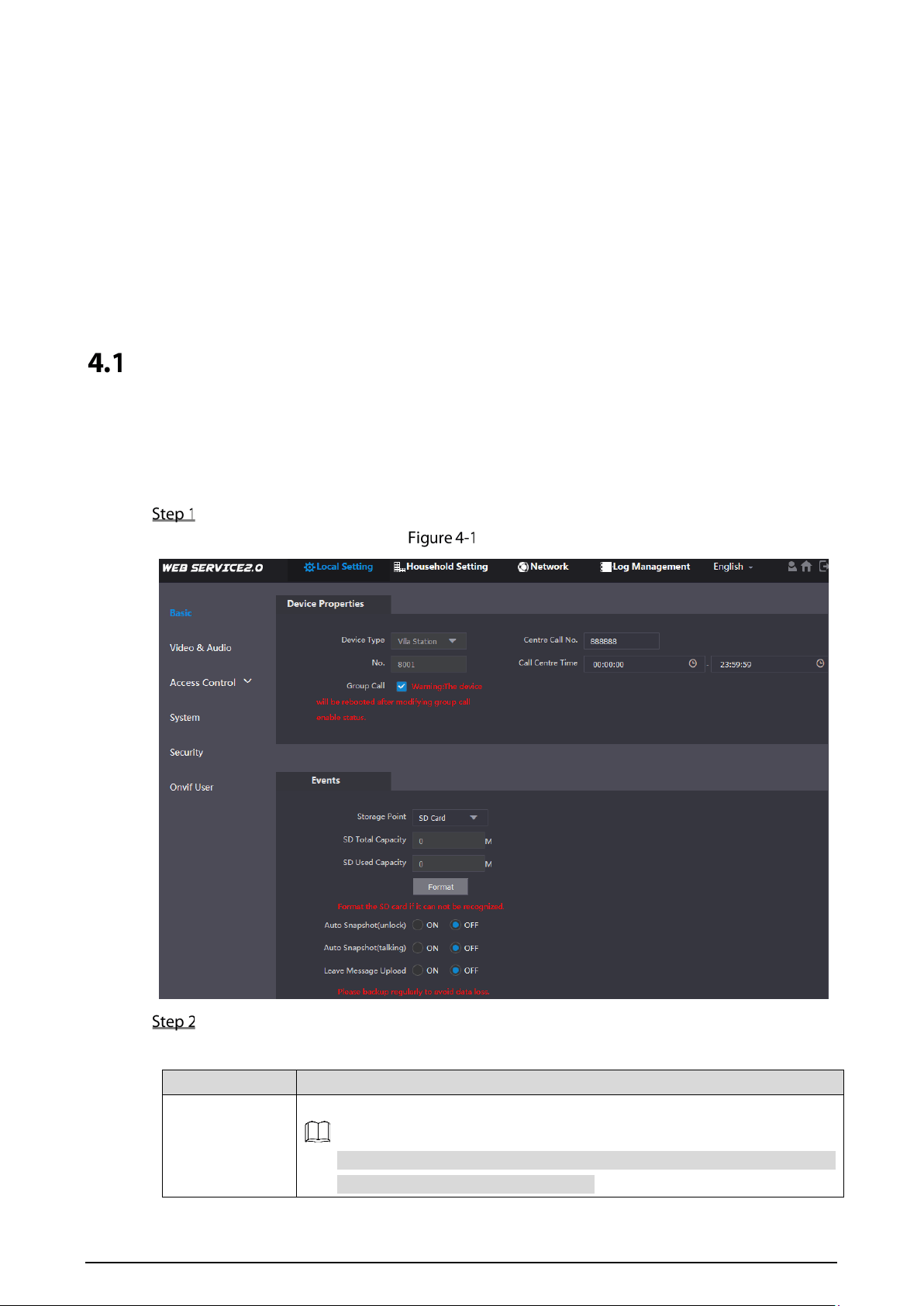
4.1.1 Device Properties & Events
This section introduces the configuration of VTO device type, VTO number, and auto storage.
On the home page, select Local Setting > Basic.
Basic
Configure parameters.
Table 4-1 Basic parameter description
Parameter Description
Device Type
Keep the default value.
Building number and unit number are available only when other servers
work as SIP server. See "6.2 SIP Server."
6
Parameter Description
Fence station is normally used when other servers work as SIP server.
Centre Call No.
Configure the number of the management centre, and you can call the
management centre on every VTO or VTH in the network. The default number
is 888888.
Call Centre Time Time period in which you are allowed to call the management centre.
VTO No.
The VTO number can be used to differentiate each VTO, and it is normally
configured according to unit or building number. You can add VTO devices to
the SIP server with their numbers.
Storage Point
All the snapshots would be saved to the SD card in the villa station
automatically.
Auto Snapshot (unlock)
Select ON to enable this function, and then the system takes snapshot every
time when the door is unlocked.
Auto Snapshot (talking)
Select ON to enable this function, and then the system takes snapshot every
time when VTH user answers a call from the VTO.
Messages
Select ON to enable this function, and then the system uploads the messages
from visitors to the SD card automatically.
If there is an SD card in the main VTH, the left messages would be saved to
the SD card of the main VTH by default.
To receive message, the VTO Message Time must be configured to be
more than 0. See the VTH user's manual.
Click Confirm.
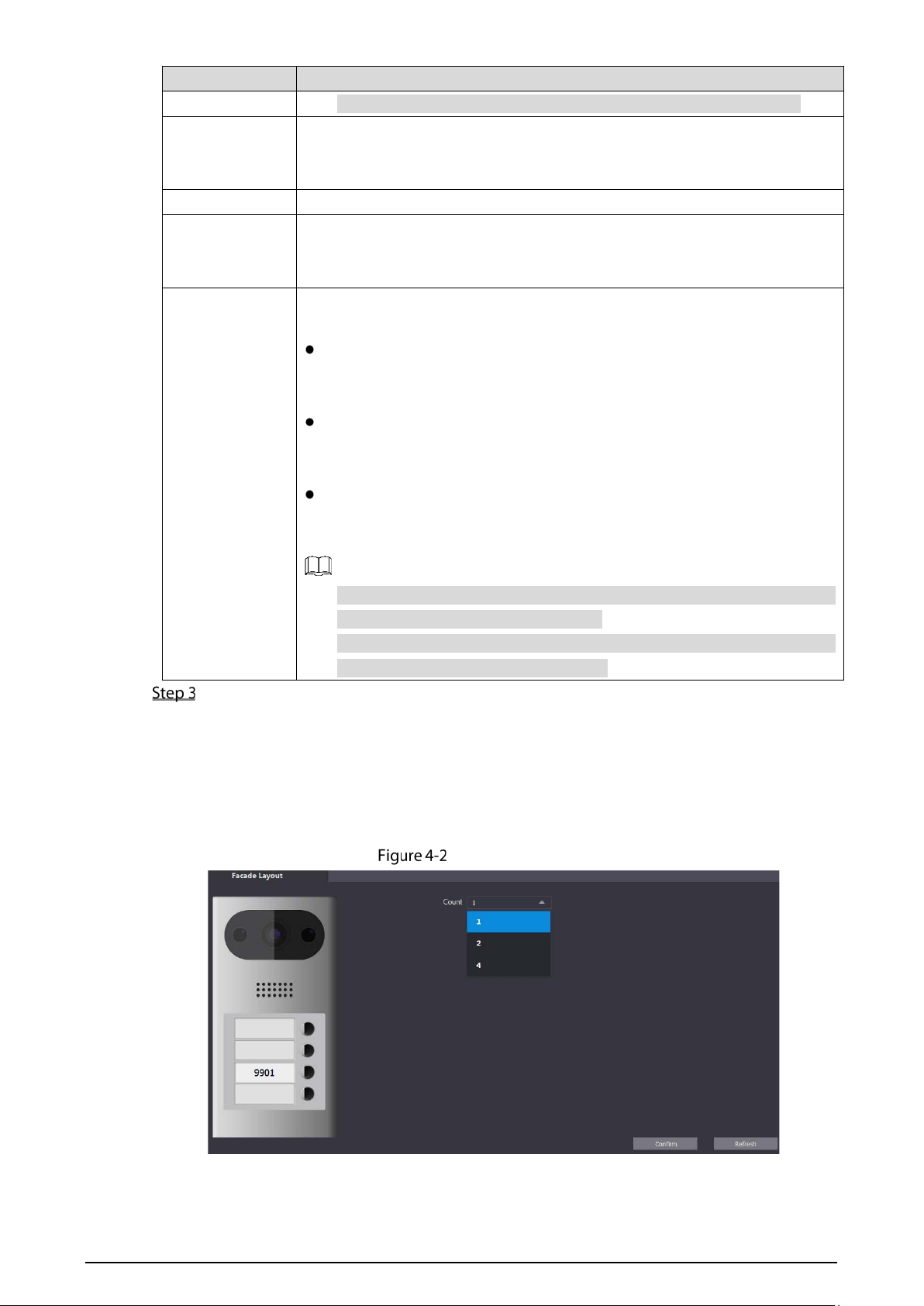
4.1.2 Facade Layout (Only for VTO3211D)
If you select 1 form the Count drop-down list, only the third button will be valid; if you select 2, only
the second and the fourth buttons will be valid; and if you select 4, all the four buttons will be valid.
Facade layout
7
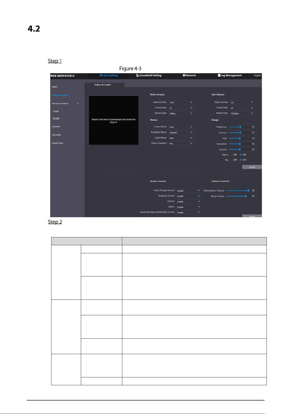
Video & Audio
This section introduces how to configure the format and quality of video that captured by VTO, and
the audio control settings.
On the home page, select Local Setting > Video & Audio.
Video & audio
Configure parameters, and these configurations will take effect immediately.
Table 4-2 Video parameter description
Parameter Description
Main
Stream
Video Format Select the video resolution from 720P, WVGA, and D1.
Format Rate
Configure the number of frames in 1 second. You can select from
1 to 25 under PAL, and 1 to 30 under NTSC video standard. The
larger the value is, the smoother the video will be.
Bitrate
Configure the data amount that transmitted in 1 second. You can
select as needed. The larger the value is, the better the video
quality will be.
Sub
Stream
Video Format
Select the video resolution from CIF, WVGA, QVGA, D1, and
1080P.
Format Rate
Configure the number of frames in 1 second. You can select from
1 to 25 under PAL, and 1 to 30 under NTSC video standard. The
larger the value is, the smoother the video will be.
Bitrate
Configure the data amount that transmitted in 1 second. The
larger the value is, the better the video quality will be.
Status
Scene Mode
Adjust the video to adapt to different scenarios. You can select
from Automatic, Sunny, Night and Disabled. It is Automatic by
default.
Day/Night Mode You can select from Disabled, Auto, Sunny or Night.
8
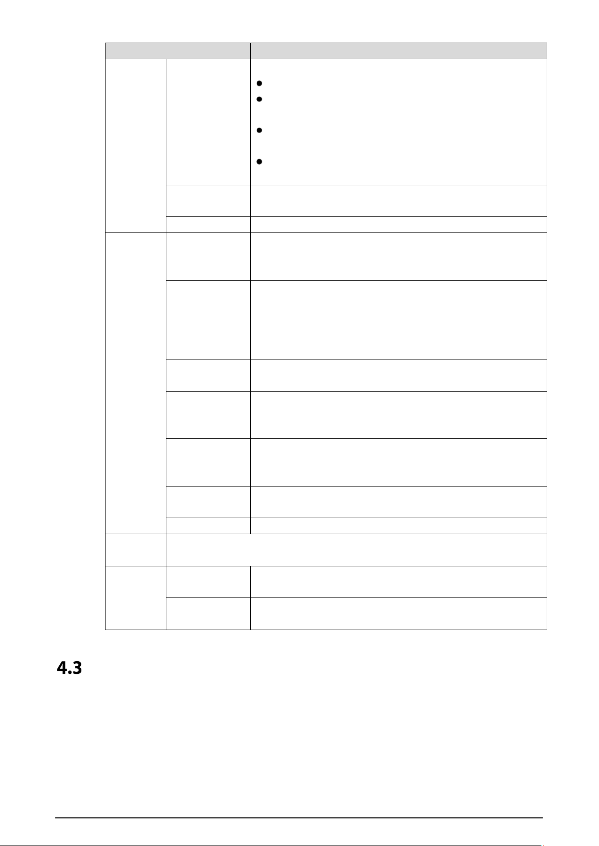
Parameter Description
BackLight Mode
You can select from the following modes:
Disabled: No back light.
BLC: The camera gets clearer image of the dark areas on the
target when shooting against light.
WDR: The system dims bright areas and compensates dark
areas to ensure the clarity of all the area.
HLC: The system constrains bright areas and reduces halo
size to dim the overall brightness.
Light Mode
There are four light modes: NO, NC, Auto, and Scheduled. Select
as needed.
Video Standard Select from PAL or NTSC according to your display device.
Image
Brightness
Changes the value to adjust the picture brightness. The larger
the value is, the brighter the picture will be, and the smaller the
darker. The picture might be hazy if the value is too large.
Contrast
Changes the contrast of the picture. The larger the value is, the
more the contrast will be between bright and dark areas, and the
smaller the less. If the value is too large, the dark area would be
too dark and bright area easier to get overexposed. The picture
might be hazy if the value is too small.
Hue
Makes the color deeper or lighter. The default value is made by the
light sensor.
Saturation
Makes the color deeper or lighter. The larger the value is, the
deeper the color will be, and the lower the lighter. Saturation
value does not change image brightness.
Gamma
Changes the picture brightness and improves the picture
dynamic range in a non-linear way. The larger the value is, the
brighter the picture will be, and the smaller the darker.
Mirror
Select On, and then the image is displayed with left and right
side reversed.
Flip Select On, and then the image is displayed upside down.
Audio
Control
Select Enable or Disabled to turn on or off each sound.
Volume
Control
Miccrophone
Volume
Adjust the value, and the larger the value is, the louder the VTO
microphone volume will be.
Beep Volume
Adjust the value, and the larger the value is, the louder the
system volume will be.
Access Control
This section introduces how to configure the lock, including unlock responding interval, open door
command, door sensor check time, first unlock command and door contact type.
9
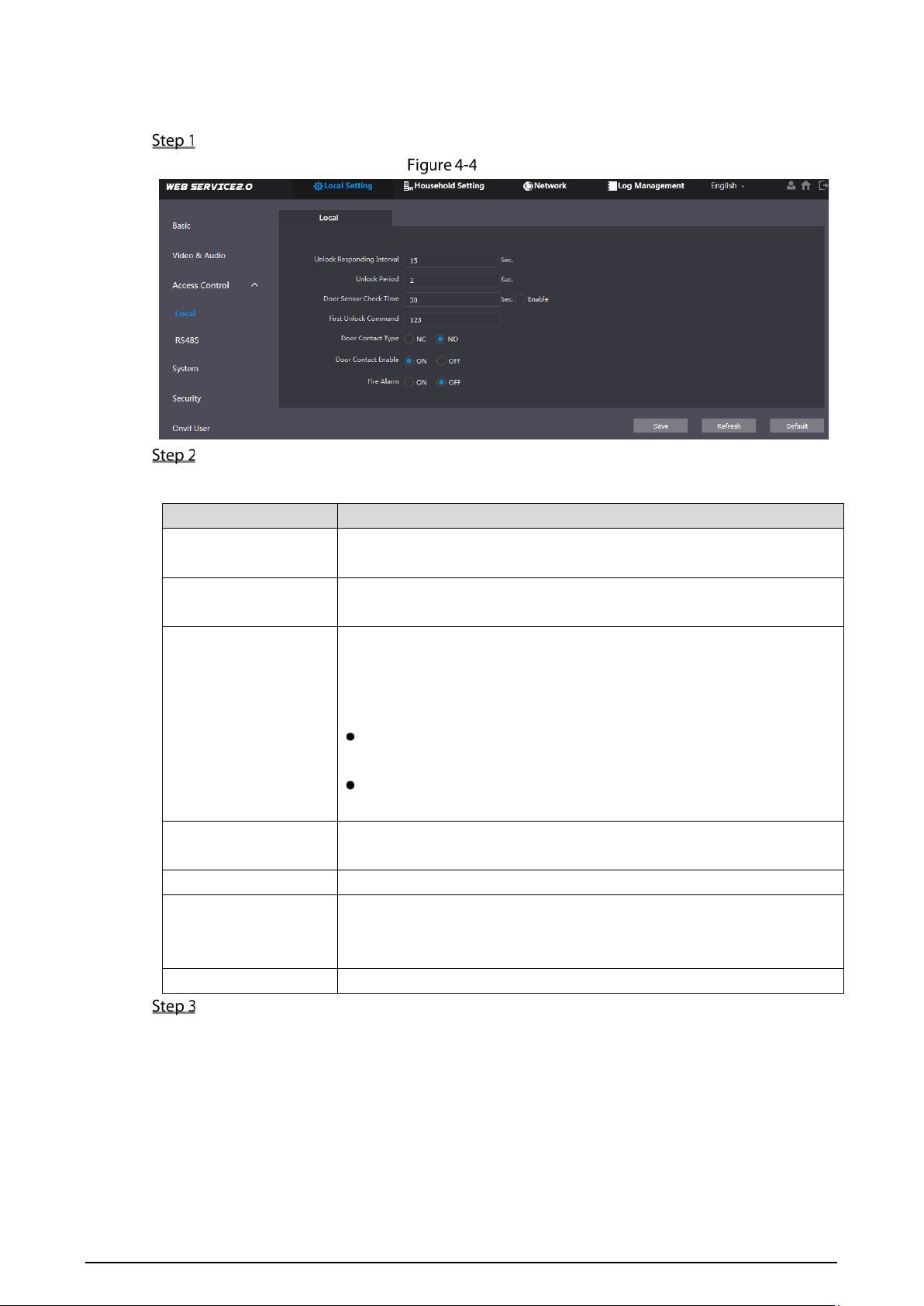
4.3.1 Local
On the home page, select Local Setting > Access Control > Local.
Local
Configure parameters.
Table 4-3 Local access control parameter description
Parameter Description
Unlock Responding
Interval
The time interval to unlock again after the previous unlock, and the unit
is second.
Unlock Period
The time amount for which the lock stays open after unlock, and the
unit is second.
Door Sensor Check
Time
If you have installed door sensor, you need to configure the time period,
and If the unlock time exceeds the Door Sensor Check Time, the door
sensor alarm is triggered, and the alarm will be sent to the management
center.
Select the Enable check box, and the door will not be locked until
the door sensor contacts each other.
If you do not select the Enable check box, the door will be locked
after the Unlock Period finishes.
First Unlock Command
You can connect a third-party phone such as SIP phone to your VTO, and
use the command to open the door remotely.
Door Contact Type Select NC or NO according to the lock you use.
Door Contact Enable
After door contact is enabled, if doors are not locked at certain period,
alarms will be triggered, and alarm messages will be pushed to the
indoor monitor (VTH).
Fire Alarm Select as needed.
Click Save.
4.3.2 RS-485
You can set unlock responding interval, unlock period, and second unlock command.
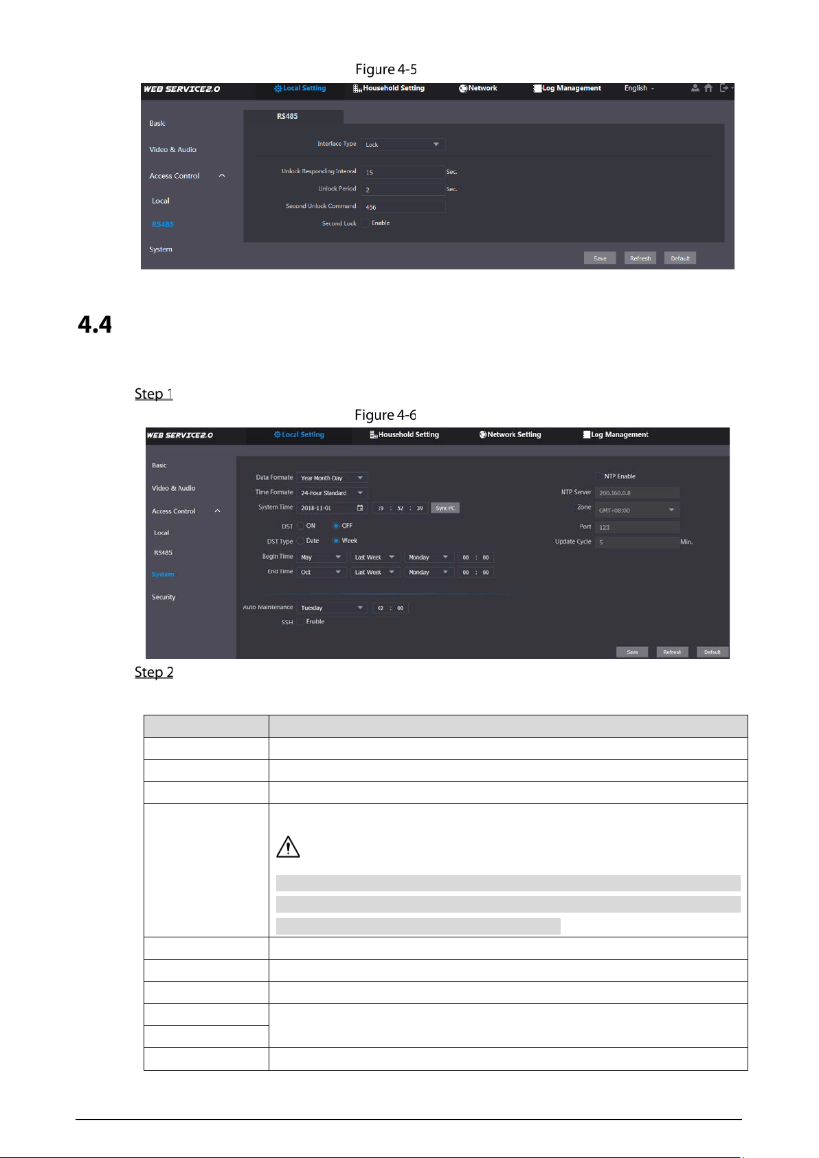
10
RS-485
System
This section introduces how to configure the date format, time format, and the NTP server.
On the home page, select Local Setting > System.
System
Configure parameters.
Table 4-4 System parameter description
Parameter Description
Date Format You can select from Year-Month-Day, Month-Day-Year, and Day-Month-Year.
Time Format Configure the time format, and you can select from 12-Hour or 24-Hour.
Time Zone Select a time zone as needed.
System Time
Configure the VTO system date, time and time zone.
Do not change the system time arbitrarily; it might cause problems on video
searching and publishing snapshot or notice. Before changing the system
time, turn off video recording or auto snapshot.
Sync PC Click to sync the VTO system time and the PC system time.
DST Select ON to enable DST.
DST Type Select Date to define a specific date for DST or select Week for it.
Start Time
Configure the begin time and end time for DST.
End Time
NTP Enable Select the check box to enable NTP timing.
11
Parameter Description
NTP Server Enter the domain name of the NTP server.
Port The port number of the NTP server.
Update Cycle
The time interval that the VTO syncs time with the NTP server, and it is 30 min
at most.
Maintenance
Select the day and time for the auto maintenance, and the VTO will restart
then.
SSH
Select the Enable check box, and then you can connect debugging devices
to the VTO through SSH protocol.
Click Save.
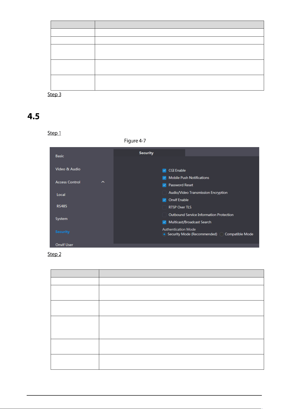
Security
On the home page, select Local Setting > Security.
Security
Configure parameters.
Table 4-5 Security parameter description
Parameter Description
CGI Enable Select the check box to enable, and then you can use CGI command.
Mobile Push
Notification
After you have enabled this, nitifications will be pushed to the app installed
on your phone.
Password Reset
Select the check box to enable, and then the password resetting is
available.
Audio/Video
Transmission
Encryption
If you have enabled this, transmission of audio and video will be encrypted.
Onvif Enable
After Onvif is enabled, videos from devices manufactured by other
companies can be displayed on the door station web page.
RTSP Over TLS
RTSP is the abbreviation of real time streaming protocol, it's a network
control protocol designed for use in entertainment and communications
12
Parameter Description
systems to control streaming media servers. The protocol is used for
establishing and controlling media sessions between end points.
Outbound Service
Information
After it is enabled, service password information cannot be sent to others.
Multicast/Broadcast
Search
If you have disabled this, VDP configure tools cannot find this device.
Authentification
Mode
There are two modes: Security Mode (Recommended) and compatible
mode.
Click Save to save.
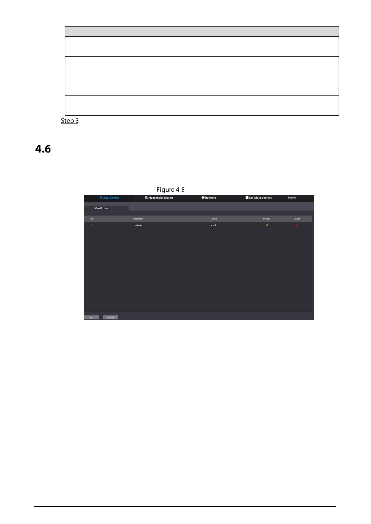
Onvif User
Onvif user is only for engineers. You can add, delete, and modify ONVIF user information. The Onvif
username is admin by default.
Onvif user
13
5 Household Setting
This chapter is about configurations to the door stations (VTO) that work as SIP servers (see 6.2 SIP
Server). You will know how to add, modify, and delete VTO, VTH, VTS, and IPC devices, and how to send
messages from the SIP server to other VTO and VTH devices. If you are using other servers as SIP server,
see the corresponding manual for the detailed configuration.
VTO No. Management
5.1.1 Adding VTO
You can add VTO to the SIP server, and then you can make video calls among video door phones that
are connected to the same SIP server.
Log in to the web page of the SIP server.
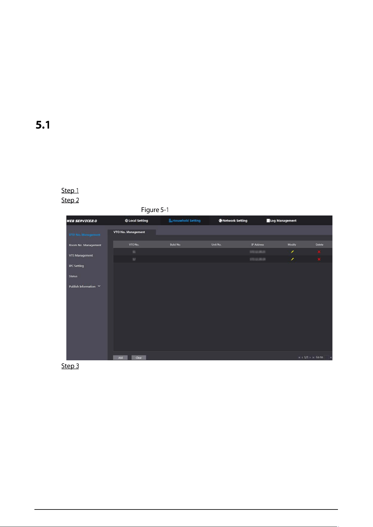
Select Household Setting > VTO No. Management.
VTO No. management
Click Add.
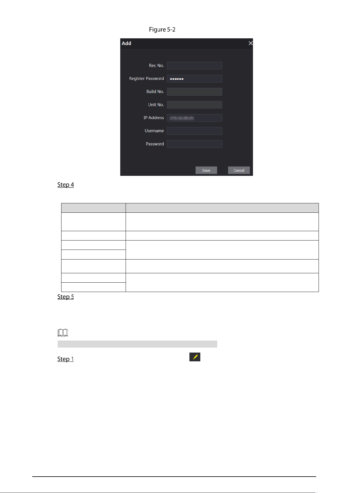
14
Add VTO
Configure the parameters.
Table 5-1 Add VTO configuration
Parameter Description
Rec No.
The VTO number you configured for the target VTO. See the details in
"Table 4-1."
Register Password Keep default value.
Build No.
Available only when other servers work as SIP server.
Unit No.
IP Address The IP address of the target VTO.
Username
The user name and password for the web page of the target VTO.
Password
Click Save.
5.1.2 Modifying VTO Information
The VTO that is currently at use cannot be modified or deleted.
On the VTO No. Management page, click .
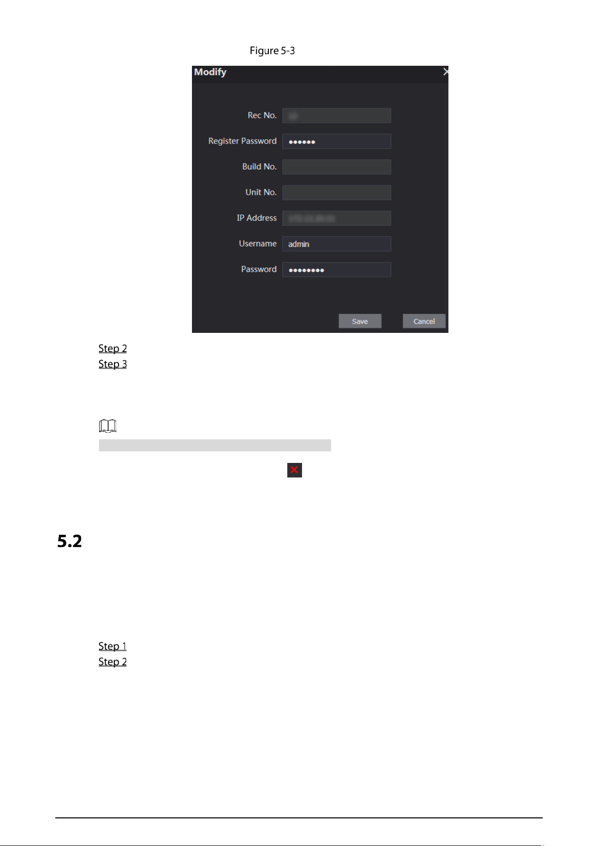
15
Modify VTO
You can modify the Rec No., Username, and Password.
Click Save.
5.1.3 Deleting VTO
The VTO that is in use cannot be modified or deleted.
On the VTO No. Management page, click to delete VTO one by one; and click Clear to delete all
the VTO.
Room No. Management
5.2.1 Adding Room Number
You can add the planned room numbers to the SIP server, and then configure room numbers on VTH
devices so that you can connect them to the network.
Log in to the web page of the SIP server.
Select Household Setting > Room No. Management.
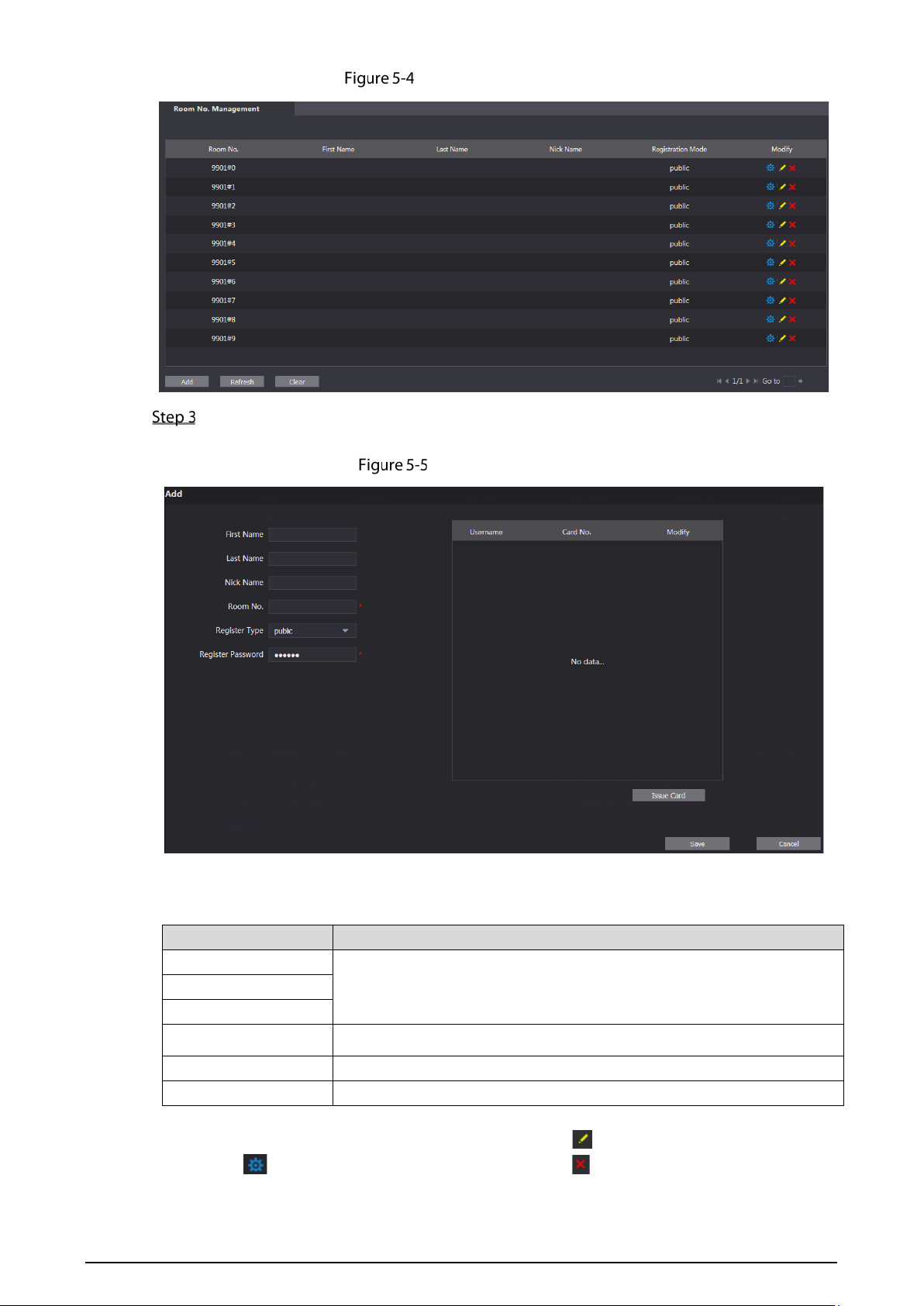
16
Room No. Management
Add room numbers.
1) Click Add.
Add room numbers
2) Configure room information.
Table 5-2 Room information
Parameter Description
First Name
Enter the information that helps to differentiate each room.
Last Name
Nick Name
Room No.
The room number you planned.
Register Type Select public, and local is reserved for future use.
Register Password Keep the default value.
3) Click Save.
The room numbers added are displayed. Click to modify room information, click
to view the device serial number, and click to delete a room. Click Refresh to
view the latest status, and click Clear to delete all the room numbers.
17
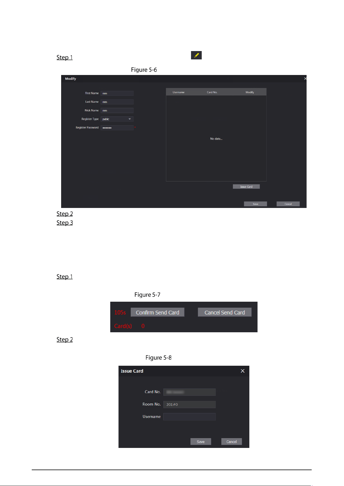
5.2.2 Modifying Room Number
On the Room No. Management page, click .
Modify room number
You can modify the names for the room.
Click Save.
5.2.3 Issuing Access Card
You can issue card to a room, and can also set the card as the main card, or set the card to the lost state.
Main cards are used to issue cards for other rooms.
On the Modify room number page, click Issue Card.
The countdown notice is displayed.
Countdown notice
Swipe the card that needs to be authorized on the VTO, and then the Issue Card dialogue box
is displayed.
Issue card
18
Enter a username, click Save, and then click Confirm Send Card at the countdown notice.
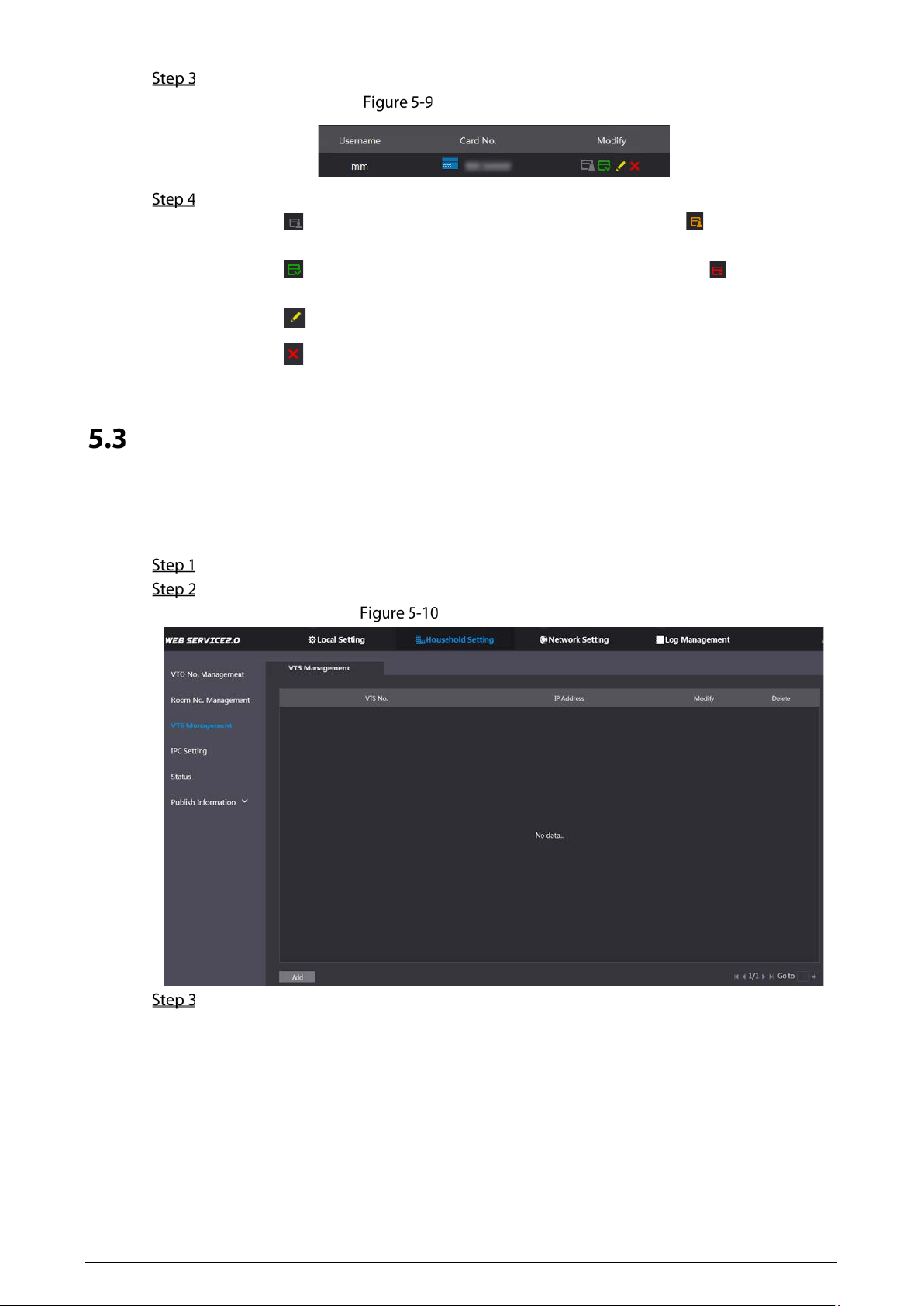
Issued access card
You can modify card information.
Click to set it to the main card, and then the icon turns into . The main card can
be used to issue access card for this room on the VTO. Click again to resume.
Click to set the card to the lost state, and then the icon turns to . The card under
lost state cannot be used to open the door. Click again to resume.
Click to modify the user name.
Click to delete the card.
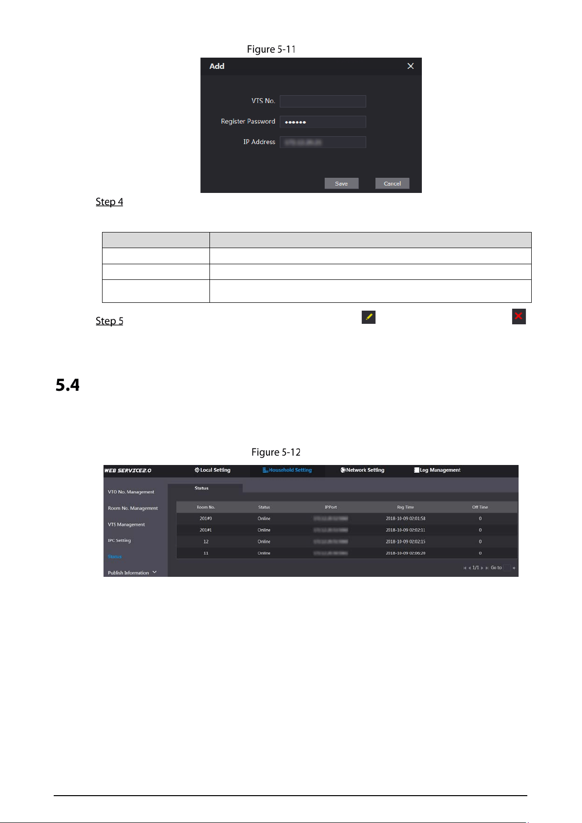
VTS Management
You can add VTS device to the SIP server, and the VTS can be used as the management center. It can
manage all the video door phones in the network, make or receive video calls, and make basic
configurations. For details, see the VTS user's manual.
Log in to the web page of the SIP server.
Select Household Setting > VTS Management.
VTS management
Click Add.
19
Add VTS
Configure the parameters, and for the detailed description.
Table 5-3 Add VTS configuration
Parameter Description
VTS No. The VTS number you configured for the target VTS.
Register Password Keep default value.
IP Address The IP address of the target VTS.
Click Save, and then the added VTS is displayed. Click to modify IP address, and click
to delete.
Status
You can view the working state and IP address of all the connected devices.
Log in to the web page of the SIP server, and then select Household Setting > Status.
Status
20
6 Network Setting
This chapter introduces how to configure IP address, SIP server, DDNS, and UPnP.
Basic
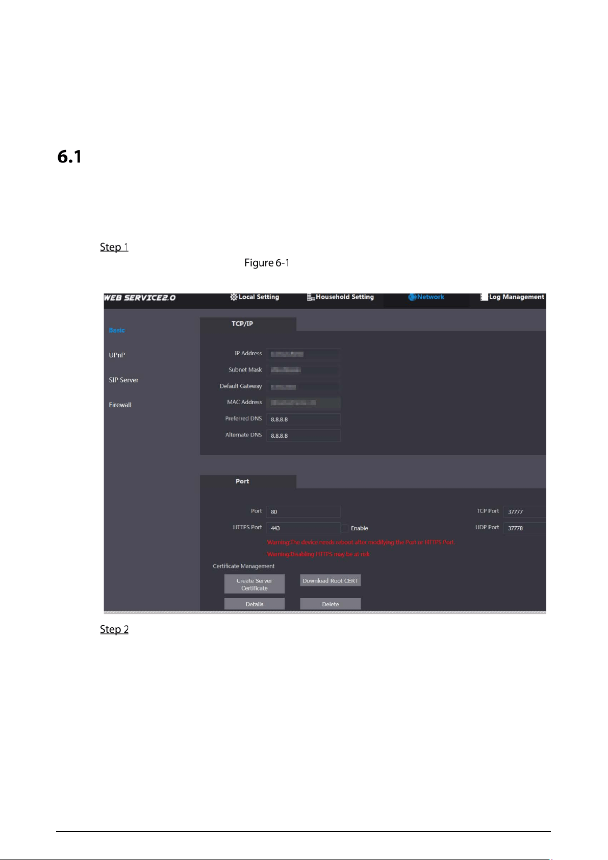
6.1.1 TCP/IP
You can modify the IP address and port number of the VTO.
Select Network Setting > Basic.
TCP/IP and port
Enter the network parameters and port number, and then click Save.
The VTO will restart, and you need to modify the IP address of your PC to the same network
segment as the VTO to log in again.
6.1.2 Port
6.1.2.1 Creating Server Certificate
Click Create Server Certificate, enter needed information, click Save, and then the terminal will
restart.
21
6.1.2.2 Downloading Root Certificate
Click Download Root Certificate.
Select a path to save the certificate on the Save File dialog box.
Double-click Root Certificate that you have downloaded to install the certificate. Install the
certificate by following the onscreen instructions.
6.1.3 HTTPS
Select the Enable check box at HTTPS Port, and then the VTO will reboot. After restart, you can log in
to the VTO by entering "https:// VTO IP address" in the address bar of the explorer.
You can use the default value, and you can also modify the port number as needed.
When HTTPS Port is enabled, you can enter https://VTO IP address:HTTPS port number/#/Login
to log in to the web page; or you can enter http://VTO IP address:port number, and the address
will be automatically changed to https://VTO IP address: HTTPS port number/#/Login.
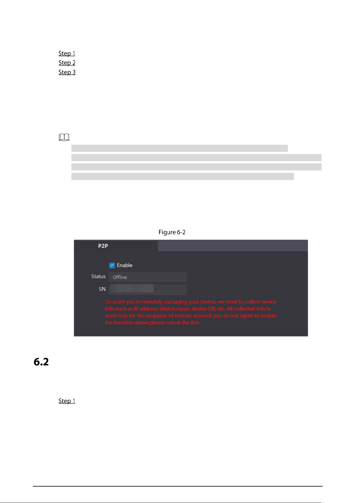
6.1.4 P2P
P2P network is one in which two or more PCs share files and access to devices such as printers without
requiring separate server computer or server software.
P2P
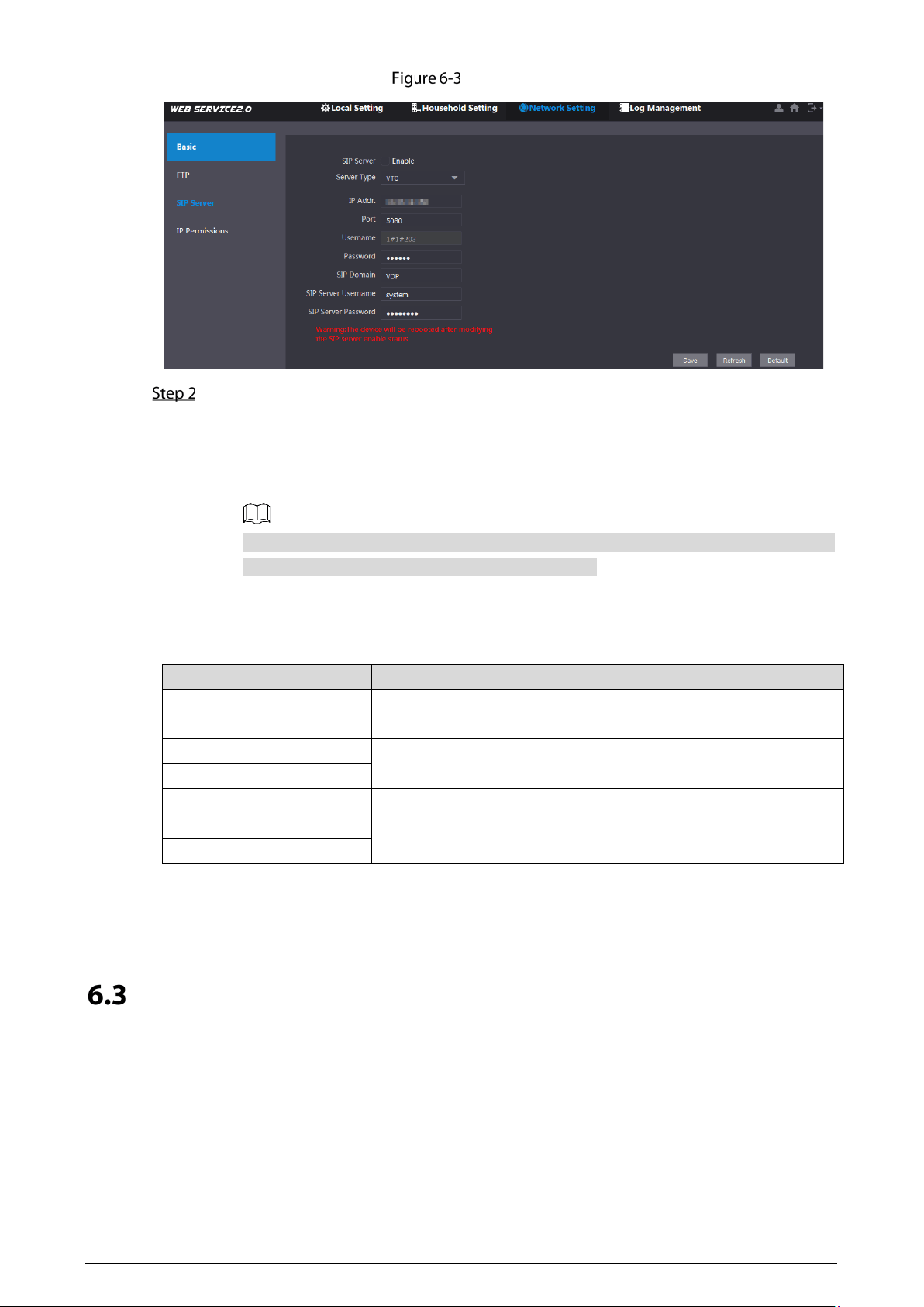
SIP Server
The SIP server is required in the network to transmit intercom protocol, and then all the VTO and VTH
devices connected to the same SIP server can make video calls among each other.
Select Network Setting > SIP Server.
22
SIP server
Select the server type you need.
If the VTO you are visiting works as SIP server
Select the Enable check box at SIP Server, and then click Save.
The VTO will reboot, and after rebooting, you can then add VTO and VTH devices to this
VTO. See the details in "5 Household Setting."
If the VTO you are visiting does not work as SIP server, do not select the Enable check
box at SIP Server, otherwise the connection will fail.
If other VTO works as SIP server
Select VTO in the Server Type list, and then configure the parameters.
Table 6-1 SIP server configuration
Parameter Description
IP Addr. The IP address of the VTO which works as SIP server.
Port 5060
Username
Keep the default value.
Password
SIP Domain VDP
SIP Server Username
The user name and password for the web page of the SIP server.
SIP Server Password
If other servers work as SIP server
Select the server type you need at Server Type, and then see the corresponding manual
for the detailed configuration.
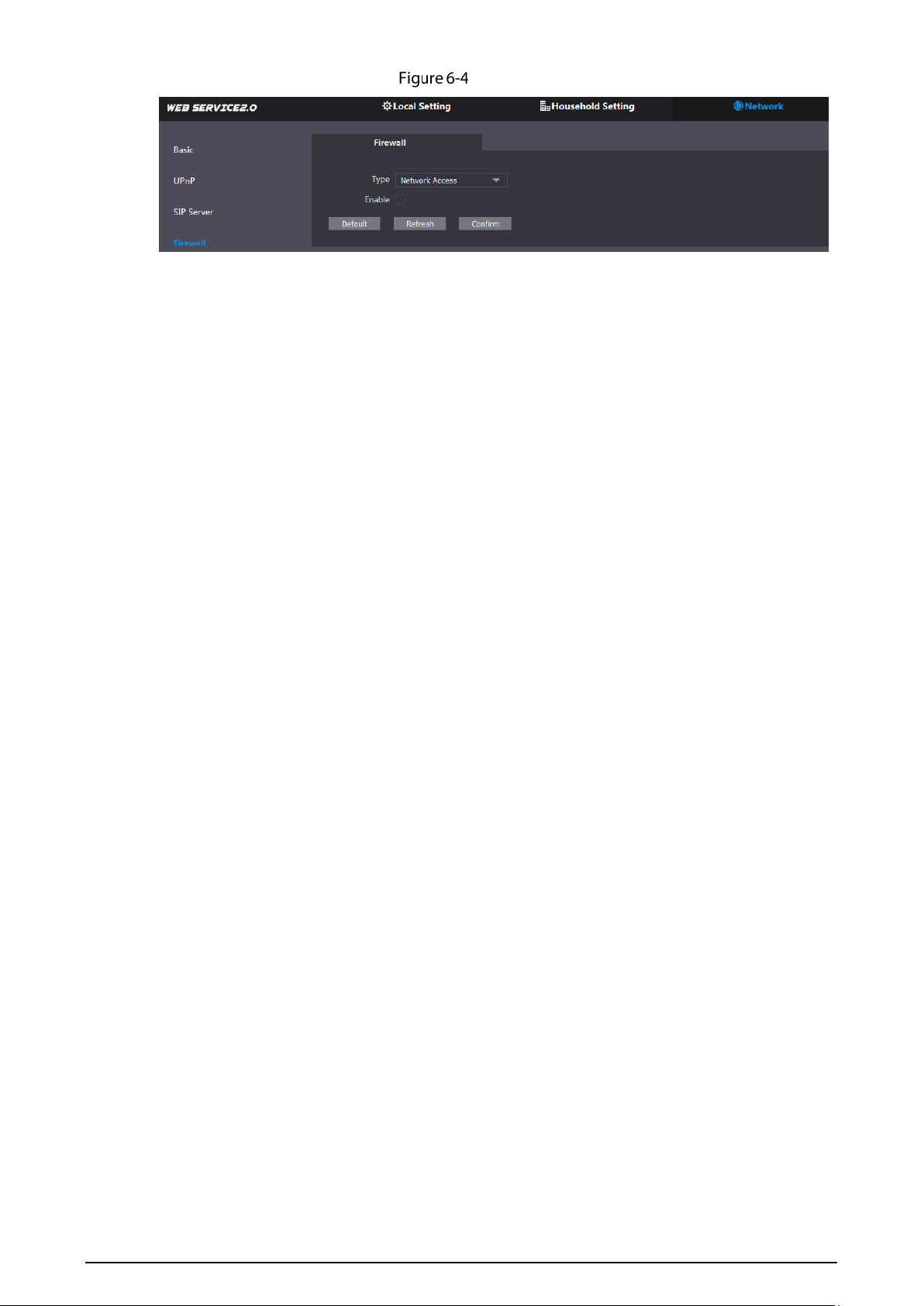
Firewall
Firewall is only for engineers.
23
Firewall
24
7 Log Management
You can view call history, alarm records, unlock records and system logs.
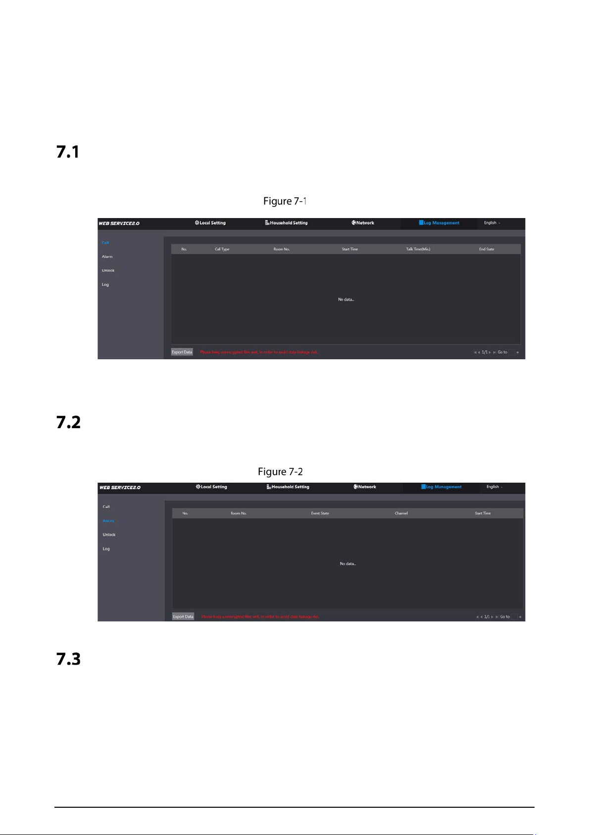
Call
You can view call logs, including call types, room numbers, start time, talk time, and end state.
Call
Click Export Data to export the records to your PC.
Alarm
You can view and export alarm logs.
Alarm
Unlock
You can view and export unlocking records, including access card unlock, password unlock, remote
unlock, and press button unlock.
25
Unlock
Click Export Data to export the records to your PC.
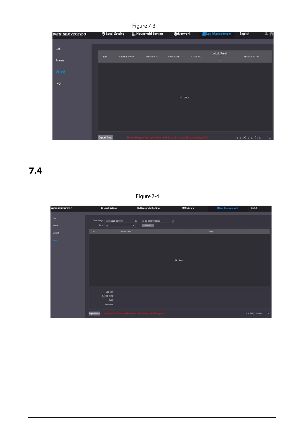
Log
You can search, view, and view logs of events in specific periods.
Log

26
Cybersecurity Recommendations
Mandatory actions to be taken for basic device network security:
1. Use Strong Passwords
Please refer to the following suggestions to set passwords:
The length should not be less than 8 characters;
Include at least two types of characters; character types include upper and lower case
letters, numbers and symbols;
Do not contain the account name or the account name in reverse order;
Do not use continuous characters, such as 123, abc, etc.;
Do not use overlapped characters, such as 111, aaa, etc.;
2. Update Firmware and Client Software in Time
According to the standard procedure in Tech-industry, we recommend to keep your device
(such as NVR, DVR, IP camera, etc.) firmware up-to-date to ensure the system is equipped
with the latest security patches and fixes. When the device is connected to the public
network, we recommend enabling the "auto-check for updates" function to obtain timely
information of firmware updates released by the manufacturer.
We suggest that you download and use the latest version of client software.
"Nice to have" recommendations to improve your device network security:
1. Physical Protection
We suggest that you perform physical protection to device, especially storage devices. For
example, place the device in a special computer room and cabinet, and implement well-done
access control permission and key management to prevent unauthorized personnel from
carrying out physical contacts such as damaging hardware, unauthorized connection of
removable device (such as USB flash disk, serial port), etc.
2. Change Passwords Regularly
We suggest that you change passwords regularly to reduce the risk of being guessed or cracked.
3. Set and Update Passwords Reset Information Timely
The device supports password reset function. Please set up related information for password
reset in time, including the end user’s mailbox and password protection questions. If the
information changes, please modify it in time. When setting password protection questions, it is
suggested not to use those that can be easily guessed.
4. Enable Account Lock
The account lock feature is enabled by default, and we recommend you to keep it on to guarantee
the account security. If an attacker attempts to log in with the wrong password several times, the
corresponding account and the source IP address will be locked.
5. Change Default HTTP and Other Service Ports
We suggest you to change default HTTP and other service ports into any set of numbers between
1024~65535, reducing the risk of outsiders being able to guess which ports you are using.
6. Enable HTTPS
We suggest you to enable HTTPS, so that you visit Web service through a secure communication
channel.
7. MAC Address Binding
We recommend you to bind the IP and MAC address of the gateway to the device, thus reducing
the risk of ARP spoofing.

27
8. Assign Accounts and Privileges Reasonably
According to business and management requirements, reasonably add users and assign a
minimum set of permissions to them.
9. Disable Unnecessary Services and Choose Secure Modes
If not needed, we recommend turning off some services such as SNMP, SMTP, UPnP, etc., to reduce
risks.
If necessary, it is highly recommended that you use safe modes, including but not limited to the
following services:
SNMP: Choose SNMP v3, and set up strong encryption passwords and authentication
passwords.
SMTP: Choose TLS to access mailbox server.
FTP: Choose SFTP, and set up strong passwords.
AP hotspot: Choose WPA2-PSK encryption mode, and set up strong passwords.
10. Audio and Video Encrypted Transmission
If your audio and video data contents are very important or sensitive, we recommend that you
use encrypted transmission function, to reduce the risk of audio and video data being stolen
during transmission.
Reminder: encrypted transmission will cause some loss in transmission efficiency.
11. Secure Auditing
Check online users: we suggest that you check online users regularly to see if the device is
logged in without authorization.
Check device log: By viewing the logs, you can know the IP addresses that were used to log
in to your devices and their key operations.
12. Network Log
Due to the limited storage capacity of the device, the stored log is limited. If you need to save the
log for a long time, it is recommended that you enable the network log function to ensure that
the critical logs are synchronized to the network log server for tracing.
13. Construct a Safe Network Environment
In order to better ensure the safety of device and reduce potential cyber risks, we recommend:
Disable the port mapping function of the router to avoid direct access to the intranet devices
from external network.
The network should be partitioned and isolated according to the actual network needs. If
there are no communication requirements between two sub networks, it is suggested to use
VLAN, network GAP and other technologies to partition the network, so as to achieve the
network isolation effect.
Establish the 802.1x access authentication system to reduce the risk of unauthorized access
to private networks.
Enable IP/MAC address filtering function to limit the range of hosts allowed to access the
device.