Loading ...
Loading ...
Loading ...
OPERATING INSTRUCTIONS
11
1) Turn the ignition off.
2) Locate the vehicle’s 16-pin Data Link Connector (DLC).
3) Plug into the OBDII cable to the vehicle’s DLC.
4) Turn the ignition on. Engine can be off or running.
5) Press ENTER/EXIT button to enter Diagnostic Menu. A sequence of messages
displaying the OBD2 protocols will be observed on the display until the vehicle
protocol is detected.
◆ If the code reader fails to communicate with the vehicle’s ECU (Engine Control
Unit), a “LINKING ERROR!” message shows up on the display.
✓ Verify that the ignition is ON;
✓ Check if the code reader’s OBD II connector is securely connected to the
vehicle’s DLC;
✓ Verify that the vehicle is OBD2 compliant;
✓ Turn the ignition off and wait for about 10 seconds. Turn the ignition back to on
and repeat the procedure from step 5.
◆ If the “LINKING ERROR” message does not go away,
then there might be problems for the code reader
to communicate with the vehicle. Contact your
local distributor or the manufacturer’s customer
service department for
assistance.
6) After the system status is displayed
(MIL status, DTC counts, Monitor status),
wait a few seconds or press any key for
Diagnostic Menu to come up.
Reading Codes
1) Use SCROLL button to select Read Codes
from Diagnostic Menu and press
ENTER/EXIT button.
• If more than one module is detected,
you will be prompted to select a module
before test.
• Use SCROLL button to select a module,
and press ENTER/EXIT button.
2) View DTCs and their definitions
on screen.
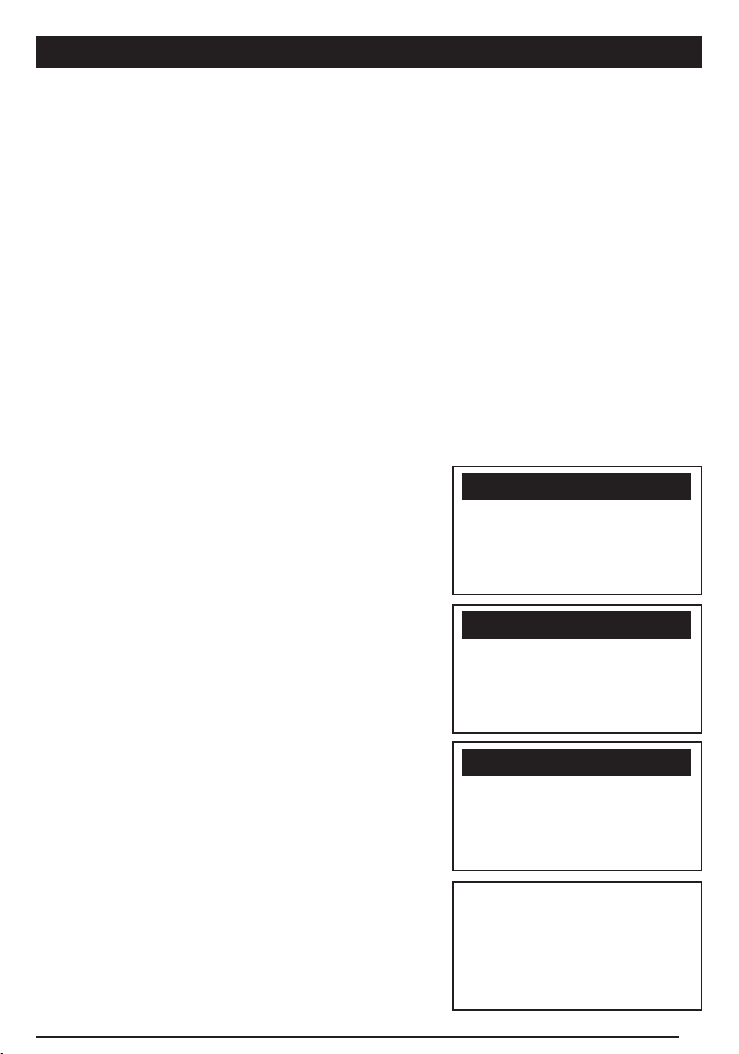
============================1/6
u 1) Read Codes
2) Erase Codes
3) View Freeze Frame
4) I/M Readiness
Diagnostic Menu
==============================
Codes Found 1
Monitors N/A 4
Monitors OK 3
Monitors INC 3
System Status
============================1/3
u Engine
Module $A4
Exit
Control Module
$11 Pd 1/6
P0115 Generic
==============================
Engine Coolant Temperature
Sensor 1 Circuit
Loading ...
Loading ...
Loading ...