Loading ...
Loading ...
Loading ...
TP-7092 2/21 25Section 2 Generator Set Operation
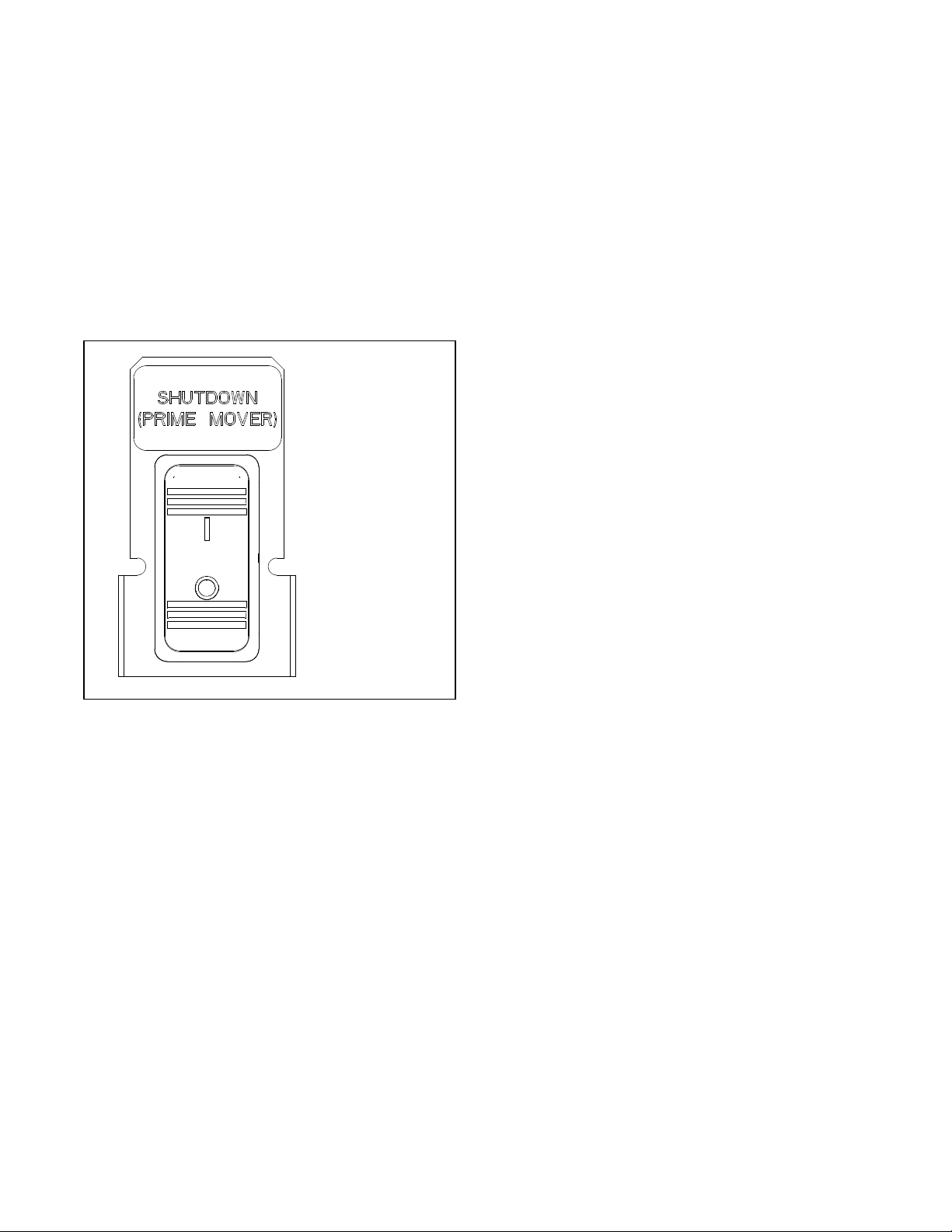
Shutdown Switch
The generator set may be equipped with a Shutdown
switch. See Figure 2-2. This switch, also referred to as
the Engine Shutdown switch, commands an immediate
shutdown and prevents an engine start if the switch is
turned to the off (open, O) position. When the shutdown
switch is activated, the controller display shows Emerg
Stop Shutdwn.
The switch is a mechanical, rocker-style switch. Press O
to prevent engine start during generator set service.
Press I to allow the engine to start and run.
See Figure 2-2 for switch connections.
dwg GM111084
I = On. The engine
is allowed to start.
O = OFF. Engine
shuts down, will not
start.
Figure 2-2 Shutdown Switch
2.3.5 Engine Start Crank Cycle
The controller attempts to start the generator set three
times (three crank cycles, 15 seconds crank and
15 seconds off). If the generator set does not start in
three attempts, the system shuts down on an overcrank
fault. See Section 2.5.
Cranking 1, 2, and 3 are displayed during the crank
cycle. Pressing the OFF button during the crank cycle
stops the cranking. No other buttons are acknowledged
during the crank cycle.
20 kW Models (RDC2.4 v1.4.4)
For RDC2.4 controllers with firmware version 1.4.4 or
later, the 20 kW models will perform two crank cycles
with 3 starting attempts during each cycle. The
controller attempts to start the generator set three times
(three starting attempts, 15 seconds crank and
15 seconds off). If the generator set does not start in
three attempts, the controller pauses for 45 seconds,
and then performs another set of 3 starting attempts. If
the generator set does not start during these crank
cycles, the system shuts down on an overcrank fault.
See Section 2.5.
2.3.6 Engine Cooldown
The engine cooldown time delay allows the engine to
run after the loads have been removed.
The engine cooldown time delay is set to 5 minutes. The
engine stops before the cooldown time delay expires if
the temperature drops below the cooled-down
temperature level, or if the temperature rises above the
high limit during the cooldown cycle.
If a transfer switch other than the Model RXT is used, an
additional engine cooldown time delay may be
programmed on the transfer switch. To allow the smart
engine cooldown on the RDC2 controller to operate
most efficiently, set the cooldown time on the transfer
switch controller to zero or the minimum time allowed.
Refer to the instructions provided with the transfer
switch for more information.
2.3.7 Automatic Operation with Model
RXT Transfer Switch
The Model RXT transfer switch connects to the RDC2
controller through the ATS interface board on the
transfer switch. Also see the Model RXT Transfer
Switch Operation/Installation Manual for more
information about transfer switch operation.
The controller must be in AUTO mode for automatic
transfer switch operation.
Automatic Start
The RDC2 controller receives utility source voltage
sensing data from the Model RXT transfer switch.
1. If the utility source voltage falls below an
acceptable level, the controller starts the engine
start time delay.
2. If the utility source is not restored before the time
delay expires, the generator set starts.
3. After the Normal-to-Emergency time delay, the
ATS is signaled to transfer the load to the
emergency source.
Loading ...
Loading ...
Loading ...