Models:
14RCA
14RCAL
20RCA
20RCAL
26RCA
26RCAL
Controller:
RDC2
Residential/Commercial Generator Sets
TP-7092 9/23e
Operation
2 TP-7092 9/23
WARNING: This product can expose you to chemicals, including carbon monoxide and
benzene, which are known to the State of California to cause cancer and birth defects or
other reproductive harm. For more information go to www.P65warnings.ca.gov
Kohler strongly recommends that only factory-
authorized dealers install and service the generator.
Product Identification Information
Product identification numbers determine service parts. Record the product identification numbers in the spaces below
immediately after unpacking the products so that the numbers are readily available for future reference. Record field-installed
kit numbers after installing the kits.
Generator Set Identification Numbers
Record the product identification numbers from the generator set nameplate(s).
Model Designation _________________________________________________________
Specification Number _______________________________________________________
Serial Number: ____________________________________________________________
Controller Identification
Record the controller description from the generator set operation manual, spec sheet, or sales invoice.
Controller Description________________________________________________________
Engine Identification
Record the product identification information from the engine nameplate.
Manufacturer_________________________________________________________________
Model Designation___________________________________________________________
Serial Number_______________________________________________________________
Accessory Number
Accessory Description
Accessory Number
Accessory Description

TP-7092 9/23 3
Table of Contents
Safety Precautions and Instructions ........................................................................................................................................ 7
Introduction .............................................................................................................................................................................. 13
Service Assistance................................................................................................................................................................... 16
Section 1. Descriptions and Service Views ........................................................................................................... 17
1.1 Introduction ............................................................................................................................................................ 17
1.2 Engine .................................................................................................................................................................... 17
1.3 Alternator ................................................................................................................................................................ 17
1.4 Generator Set Enclosure ........................................................................................................................................ 17
1.5 Transfer Switch ...................................................................................................................................................... 17
1.6 Controller ................................................................................................................................................................ 18
1.7 OnCue® Plus Generator Management System ..................................................................................................... 20
1.8 Accessories ............................................................................................................................................................ 20
1.8.1 Cold Weather Package Kit ....................................................................................................................... 20
1.8.2 Battery Heater Kit ..................................................................................................................................... 21
1.8.3 Breather Tube Heater and Oil Heater Kit ................................................................................................. 22
1.8.4 Fuel Regulator Heater (20 and 26 kW models only) ................................................................................ 23
1.8.5 Oil Pressure Sensor Boot Kit ................................................................................................................... 24
1.8.6 Carburetor Heater .................................................................................................................................... 24
1.8.7 Emergency Stop Kit ................................................................................................................................. 25
1.8.8 Load Management ................................................................................................................................... 25
1.8.9 PowerSync Automatic Paralleling Module (APM) .................................................................................... 26
1.8.10 Programmable Interface Module (PIM) .................................................................................................... 26
1.9 Service Views ......................................................................................................................................................... 27
Section 2. Generator Set Operation ....................................................................................................................... 29
2.1 Prestart Checklist ................................................................................................................................................... 29
2.2 Exercising the Generator Set ................................................................................................................................. 29
2.3 Generator Set Operation ........................................................................................................................................ 29
2.3.1 Local Starting and Stopping ..................................................................................................................... 30
2.3.2 Automatic Operation ................................................................................................................................ 30
2.3.3 Remote Starting and Stopping ................................................................................................................. 30
2.3.4 Remote Emergency Stop Switch ............................................................................................................. 30
2.3.5 Engine Start Crank Cycle ......................................................................................................................... 32
2.3.6 Engine Cooldown ..................................................................................................................................... 32
2.3.7 Automatic Operation with Model RXT Transfer Switch ............................................................................ 32
2.3.8 Automatic Operation with Other Transfer Switches ................................................................................. 32
2.4 Exercise ................................................................................................................................................................. 33
2.4.1 Setting the Exerciser ................................................................................................................................ 33
2.4.2 Unloaded Cycle Exercise with Complete System Diagnostics ................................................................. 33
2.4.3 EcoExercise (26RCA/L only) .................................................................................................................... 34
2.4.4 Unloaded Full-Speed Exercise ................................................................................................................. 34
2.4.5 Loaded Full-Speed Exercise (with RXT only) ........................................................................................... 34
2.4.6 Shutdown During Exercise (Advanced Diagnostic) .................................................................................. 35
2.4.7 Power Failure During Exercise Cycle ....................................................................................................... 35
2.5 Faults ..................................................................................................................................................................... 35
2.5.1 Warnings .................................................................................................................................................. 35
2.5.2 Shutdowns ............................................................................................................................................... 35
2.5.3 Shutdown During Exercise (Advanced Diagnostic) .................................................................................. 35
2.5.4 ATS Communication Errors ..................................................................................................................... 35

4 TP-7092 9/23
2.5.5 Resetting the Controller After a Fault Shutdown ...................................................................................... 36
2.5.6 Faults Related to Paralleling .................................................................................................................... 39
Section 3. RDC2 Controller Operation ................................................................................................................... 41
3.1 RDC2 Generator Set/Transfer Switch Controller .................................................................................................... 41
3.2 Control and Indicators ............................................................................................................................................ 41
3.2.1 Controller Keypad .................................................................................................................................... 42
3.2.2 LED Indicators ......................................................................................................................................... 43
3.2.3 LCD Display ............................................................................................................................................. 43
3.3 Controller Power .................................................................................................................................................... 44
3.4 Battery Charging .................................................................................................................................................... 44
3.5 Changing Settings .................................................................................................................................................. 45
3.6 Setting the Exerciser .............................................................................................................................................. 47
3.6.1 Setting the Exerciser at Controller Power-up ........................................................................................... 47
3.6.2 Changing the Exercise Settings ............................................................................................................... 47
3.7 RDC2 Controller Menus ......................................................................................................................................... 49
3.8 Main Menu ............................................................................................................................................................. 49
3.9 Overview Menu ...................................................................................................................................................... 50
3.10 Engine Metering Menu ........................................................................................................................................... 51
3.11 Generator Metering Menu ...................................................................................................................................... 52
3.12 Generator Set Information Menu ............................................................................................................................ 53
3.13 Genset Run Time Menu ......................................................................................................................................... 53
3.14 Genset System Menu ............................................................................................................................................. 54
3.15 ATS Status Menu ................................................................................................................................................... 56
3.16 ATS Configuration Menu ........................................................................................................................................ 57
3.17 Date and Time Menu .............................................................................................................................................. 58
3.18 Networking Information Menus ............................................................................................................................... 58
3.18.1 Networking Status Submenu .................................................................................................................... 59
3.18.2 Networking Configuration Submenu (OnCue® Password) ...................................................................... 60
3.18.3 RBUS Information .................................................................................................................................... 62
3.18.4 Remote Devices Submenu ...................................................................................................................... 63
3.19 Programmable Interface Module (PIM) Status Menu ............................................................................................. 64
3.20 Load Control Menus ............................................................................................................................................... 65
3.21 Event Log ............................................................................................................................................................... 66
Section 4. Scheduled Maintenance ........................................................................................................................ 67
4.1 Scheduled Maintenance ......................................................................................................................................... 67
4.1.1 Service Schedule, 14 kW Models ............................................................................................................ 68
4.1.2 Service Schedule, 20 and 26 kW Models ................................................................................................ 69
4.2 Lubrication System ................................................................................................................................................. 70
4.2.1 Low Oil Pressure Shutdown ..................................................................................................................... 70
4.2.2 Low Oil Level Switch (26RCA) ................................................................................................................. 70
4.2.3 Oil Check ................................................................................................................................................. 70
4.2.4 Engine Oil Recommendation ................................................................................................................... 71
4.2.5 Oil Change Procedure ............................................................................................................................. 71
4.2.6 Resetting the Maintenance Timer ............................................................................................................ 72
4.2.7 Oil Cooler (20RCA/L and 26RCA/L only) ................................................................................................. 73
4.3 Spark Plugs ............................................................................................................................................................ 73
4.4 Air Cleaner Service ................................................................................................................................................ 75
4.4.1 Air Cleaner, 14 kW Models ...................................................................................................................... 75
4.4.2 Air Cleaner, 20/26 kW Models ................................................................................................................. 76
4.5 Cooling System ...................................................................................................................................................... 77
4.6 Exhaust System ..................................................................................................................................................... 77

TP-7092 9/23 5
4.7 Battery .................................................................................................................................................................... 77
4.7.1 Cleaning the battery ................................................................................................................................. 78
4.7.2 Checking Electrolyte Level ....................................................................................................................... 78
4.7.3 Checking Specific Gravity ........................................................................................................................ 79
4.8 Storage Procedure ................................................................................................................................................. 80
4.8.1 Lubricating System .................................................................................................................................. 80
4.8.2 Fuel System ............................................................................................................................................. 80
4.8.3 Cylinder Lubrication ................................................................................................................................. 80
4.8.4 Exterior Preparation ................................................................................................................................. 80
4.8.5 Battery ..................................................................................................................................................... 80
Section 5. Troubleshooting ..................................................................................................................................... 81
5.1 Introduction ............................................................................................................................................................ 81
5.2 Fault Messages ...................................................................................................................................................... 81
5.3 Circuit Protection .................................................................................................................................................... 81
5.3.1 Controller Internal Circuit Protection ........................................................................................................ 81
5.3.2 Line Circuit Breaker ................................................................................................................................. 81
5.4 USB Port and Auxiliary Winding Mini-Breaker ........................................................................................................ 82
5.5 Stop Switches ........................................................................................................................................................ 82
5.6 Thermostat ............................................................................................................................................................. 82
5.7 Troubleshooting ..................................................................................................................................................... 84
Appendix A. Abbreviations ......................................................................................................................................... 85

6 TP-7092 9/23
TP-7092 9/23 7
Safety Precautions and Instructions
IMPORTANT SAFETY INSTRUCTIONS. Electromechanical equipment, including generator sets, transfer switches, switchgear,
and accessories, can cause bodily harm and pose life-threatening danger when improperly installed, operated, or maintained.
To prevent accidents be aware of potential dangers and act safely. Read and follow all safety precautions and instructions.
SAVE THESE INSTRUCTIONS.
This manual has several types of safety precautions and instructions: Danger, Warning, Caution, and Notice.
DANGER
DANGER indicates a hazardous situation which, if not avoided, will result in death or serious injury.
WARNING
WARNING indicates a hazardous situation which, if not avoided, could result in death or serious injury.
CAUTION
CAUTION indicates a hazardous situation which, if not avoided, could result in minor or moderate injury.
NOTICE
NOTICE is used to address practices not related to physical injury.
Safety decals affixed to the equipment in prominent places alert the operator or service technician to potential hazards and
explain how to act safely. The decals are shown throughout this publication to improve operator recognition. Replace missing or
damaged decals.
Accidental Starting
WARNING
Accidental starting.
Can cause severe injury or death.
Disconnect the battery cables before working on the generator set. Remove the
negative (–) lead first when disconnecting the battery. Reconnect the negative (–)
lead last when reconnecting the battery.
Disabling the generator set. Accidental starting can cause severe injury or death. Before working on the generator set or
equipment connected to the set, disable the generator set as follows: (1) Press the generator set off/reset button to shut down
the generator set. (2) Disconnect the power to the battery charger, if equipped. (3) Remove the battery cables, negative (–) lead
first. Reconnect the negative (–) lead last when reconnecting the battery. Follow these precautions to prevent the starting of the
generator set by the remote start/stop switch.
8 TP-7092 9/23
Battery
WARNING
Sulfuric acid in batteries.
Can cause severe injury or death.
Wear protective goggles and clothing. Battery acid may cause blindness and burn skin.
WARNING
Explosion.
Can cause severe injury or death.
Relays in the battery charger cause arcs or sparks.
Locate the battery in a well‐ventilated area. Isolate the battery charger from explosive
fumes.
Battery electrolyte is a diluted sulfuric acid. Battery acid can cause severe injury or death. Battery acid can cause
blindness and burn skin. Always wear splashproof safety goggles, rubber gloves, and boots when servicing the battery. Do not
open a sealed battery or mutilate the battery case. If battery acid splashes in the eyes or on the skin, immediately flush the
affected area for 15 minutes with large quantities of clean water. Seek immediate medical aid in the case of eye contact. Never
add acid to a battery after placing the battery in service, as this may result in hazardous spattering of battery acid.
Battery acid cleanup. Battery acid can cause severe injury or death. Battery acid is electrically conductive and corrosive.
Add 500 g (1 lb.) of bicarbonate of soda (baking soda) to a container with 4 L (1 gal.) of water and mix the neutralizing solution.
Pour the neutralizing solution on the spilled battery acid and continue to add the neutralizing solution to the spilled battery acid
until all evidence of a chemical reaction (foaming) has ceased. Flush the resulting liquid with water and dry the area.
Battery gases. Explosion can cause severe injury or death. Battery gases can cause an explosion. Do not smoke or permit
flames or sparks to occur near a battery at any time, particularly when it is charging. Do not dispose of a battery in a fire. To
prevent burns and sparks that could cause an explosion, avoid touching the battery terminals with tools or other metal objects.
Remove all jewelry before servicing the equipment. Discharge static electricity from your body before touching batteries by first
touching a grounded metal surface away from the battery. To avoid sparks, do not disturb the battery charger connections while
the battery is charging. Always turn the battery charger off before disconnecting the battery connections. Ventilate the
compartments containing batteries to prevent accumulation of explosive gases.
Battery short circuits. Explosion can cause severe injury or death. Short circuits can cause bodily injury and/or equipment
damage. Disconnect the battery before generator set installation or maintenance. Remove all jewelry before servicing the
equipment. Use tools with insulated handles. Remove the negative (–) lead first when disconnecting the battery. Reconnect the
negative (–) lead last when reconnecting the battery. Never connect the negative (–) battery cable to the positive (+) connection
terminal of the starter solenoid. Do not test the battery condition by shorting the terminals together.

TP-7092 9/23 9
Engine Backfire/Flash Fire
WARNING
Risk of fire.
Can cause severe injury or death.
Do not smoke or permit flames or sparks near fuels or the fuel system.
Servicing the fuel system. A flash fire can cause severe injury or death. Do not smoke or permit flames or sparks near the
carburetor, fuel line, fuel filter, fuel pump, or other potential sources of spilled fuels or fuel vapors. Catch fuels in an approved
container when removing the fuel line or carburetor.
Servicing the air cleaner. A sudden backfire can cause severe injury or death. Do not operate the generator set with the
air cleaner removed.
Combustible materials. A fire can cause severe injury or death. Generator set engine fuels and fuel vapors are flammable
and explosive. Handle these materials carefully to minimize the risk of fire or explosion. Equip the compartment or nearby area
with a fully charged fire extinguisher. Select a fire extinguisher rated ABC or BC for electrical fires or as recommended by the
local fire code or an authorized agency. Train all personnel on fire extinguisher operation and fire prevention procedures.
Exhaust System
WARNING
Carbon monoxide.
Can cause severe nausea, fainting, or death.
The exhaust system must be leakproof and routinely inspected.
Generator set operation. Carbon monoxide can cause severe nausea, fainting, or death. Carbon monoxide is an odorless,
colorless, tasteless, nonirritating gas that can cause death if inhaled for even a short time. Avoid breathing exhaust fumes when
working on or near the generator set. Never operate the generator set inside a building unless the exhaust gas is piped safely
outside. Never operate the generator set where exhaust gas could accumulate and seep back inside a potentially occupied
building.
Carbon monoxide detectors. Carbon monoxide can cause severe nausea, fainting, or death. Install carbon monoxide
detectors on each level of any building adjacent to the generator set. Locate the detectors to adequately warn the building’s
occupants of the presence of carbon monoxide. Keep the detectors operational at all times. Periodically test and replace the
carbon monoxide detectors according to the manufacturer’s instructions.
Carbon monoxide symptoms. Carbon monoxide can cause severe nausea, fainting, or death. Carbon monoxide is a
poisonous gas present in exhaust gases. Carbon monoxide is an odorless, colorless, tasteless, nonirritating gas that can cause
death if inhaled for even a short time. Carbon monoxide poisoning symptoms include but are not limited to the following:
• Light-headedness, dizziness
• Physical fatigue, weakness in joints and muscles
• Sleepiness, mental fatigue, inability to concentrate or speak clearly, blurred vision
• Stomachache, vomiting, nausea
If experiencing any of these symptoms and carbon monoxide poisoning is possible, seek fresh air immediately and remain active.
Do not sit, lie down, or fall asleep. Alert others to the possibility of carbon monoxide poisoning. Seek medical attention if the
condition of affected persons does not improve within minutes of breathing fresh air.
10 TP-7092 9/23
Fuel System
WARNING
Explosive fuel vapors.
Can cause severe injury or death.
Use extreme care when handling, storing, and using fuels.
The fuel system. Explosive fuel vapors can cause severe injury or death. Vaporized fuels are highly explosive. Use extreme
care when handling and storing fuels. Store fuels in a well-ventilated area away from spark-producing equipment and out of the
reach of children. Never add fuel to the tank while the engine is running because spilled fuel may ignite on contact with hot parts
or from sparks. Do not smoke or permit flames or sparks to occur near sources of spilled fuel or fuel vapors. Keep the fuel lines
and connections tight and in good condition. Do not replace flexible fuel lines with rigid lines. Use flexible sections to avoid fuel
line breakage caused by vibration. Do not operate the generator set in the presence of fuel leaks, fuel accumulation, or sparks.
Repair fuel systems before resuming generator set operation.
Gas fuel leaks. Explosive fuel vapors can cause severe injury or death. Fuel leakage can cause an explosion. Check the
LPG vapor or natural gas fuel system for leakage by using a soap and water solution with the fuel system test pressurized to 6–
8 ounces per square inch (10–14 inches water column). Do not use a soap solution containing either ammonia or chlorine
because both prevent bubble formation. A successful test depends on the ability of the solution to bubble.
Hazardous Noise
CAUTION
Hazardous noise.
Can cause hearing loss.
Never operate the generator set without a muffler or with a faulty exhaust system.
Engine noise. Hazardous noise can cause hearing loss. Generator sets not equipped with sound enclosures can produce
noise levels greater than 105 dBA. Prolonged exposure to noise levels greater than 85 dBA can cause permanent hearing loss.
Wear hearing protection when near an operating generator set.
TP-7092 9/23 11
Hazardous Voltage/Moving Parts
DANGER
Hazardous voltage.
Will cause severe injury or death.
This equipment must be installed and serviced by qualified electrical personnel.
DANGER
Hazardous voltage. Moving parts.
Will cause severe injury or death.
Operate the generator set only when all guards and electrical enclosures are in place.
WARNING
Hazardous voltage. Backfeed to the utility system.
Can cause property damage, severe injury, or death.
If the generator set is used for standby power, install an automatic transfer switch to
prevent inadvertent interconnection of standby and normal sources of supply.
Grounding electrical equipment. Hazardous voltage will cause severe injury or death. Electrocution is possible whenever
electricity is present. Ensure you comply with all applicable codes and standards. Electrically ground the generator set and
related equipment and electrical circuits. Turn off the main circuit breakers of all power sources before servicing the equipment.
Never contact electrical leads or appliances when standing in water or on wet ground because these conditions increase the
risk of electrocution.
CAUTION
Welding the generator set.
Can cause severe electrical equipment damage.
Welding on generator set will cause serious damage to engine electronic controls components. Disconnect all engine
electronic control connections before welding.
Welding on the generator set. Can cause severe electrical equipment damage. Before welding on the generator set perform
the following steps: (1) Remove the battery cables, negative (–) lead first. (2) Disconnect all engine electronic control module
(ECM) connectors. (3) Disconnect all generator set controller and voltage regulator circuit board connectors. (4) Disconnect the
engine battery-charging alternator connections. (5) Attach the weld ground connection close to the weld location.
Connecting the battery and the battery charger. Hazardous voltage will cause severe injury or death. Reconnect the
battery correctly, positive to positive and negative to negative, to avoid electrical shock and damage to the battery charger and
battery(ies). Have a qualified electrician install the battery(ies).
Short circuits. Hazardous voltage/current will cause severe injury or death. Short circuits can cause bodily injury and/or
equipment damage. Do not contact electrical connections with tools or jewelry while making adjustments or repairs. Remove all
jewelry before servicing the equipment.
Electrical backfeed to the utility. Hazardous backfeed voltage can cause severe injury or death. Install a transfer switch
in standby power installations to prevent the connection of standby and other sources of power. Electrical backfeed into a utility
electrical system can cause severe injury or death to utility personnel working on power lines.

12 TP-7092 9/23
Heavy Equipment
WARNING
Unbalanced weight.
Improper lifting can cause severe injury or death and equipment damage.
Do not use lifting eyes. Lift the generator set using lifting bars inserted through the lifting
holes on the skid.
Hot Parts
WARNING
Hot engine and exhaust system.
Can cause severe injury or death.
Do not work on the generator set until it cools.
Servicing the exhaust system. Hot parts can cause severe injury or death. Do not touch hot engine parts. The engine and
exhaust system components become extremely hot during operation.
Servicing the engine heater. Hot parts can cause minor personal injury or property damage. Install the heater before
connecting it to power. Operating the heater before installation can cause burns and component damage. Disconnect power to
the heater and allow it to cool before servicing the heater or nearby parts.
NOTICE
Canadian installations only. For standby service connect the output of the generator set to a suitably rated transfer switch in
accordance with Canadian Electrical Code, Part 1.

TP-7092 9/23 13
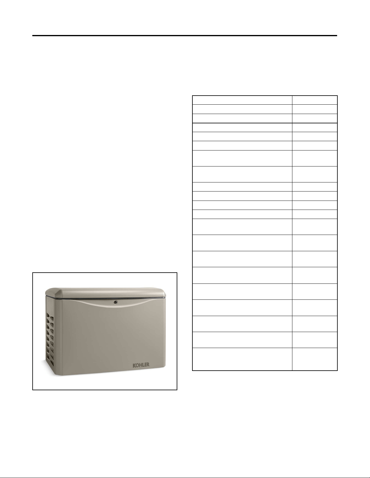
Introduction
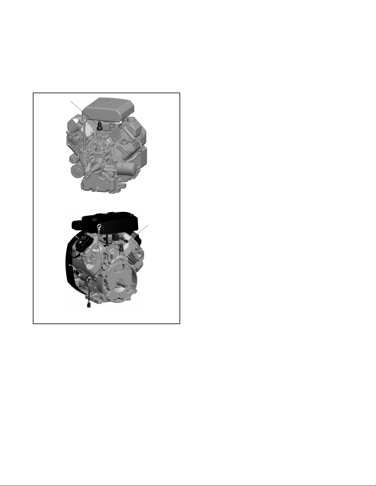
This manual provides operation and maintenance instructions for Residential/Commercial Model 14RCA/RCAL, 20RCA/RCAL,
and 26RCA/RCAL generator sets equipped with the RDC2 generator set/transfer switch controller. See Figure 1.
RCAL models are shipped with a Kohler model RXT Automatic Transfer Switch (ATS). The ATS Operation/Installation Manuals
are included with the transfer switch.
Kohler strongly recommends that only factory authorized dealers install and service the generator.
Have the generator set installed outdoors by an authorized dealer or service technician. Refer to the Installation Manual for
installation instructions. Do not install or operate the generator set indoors.
Information in this publication represents data available at the time of print. Kohler Co. reserves the right to change this
publication and the products represented without notice and without any obligation or liability whatsoever.
Read this manual and carefully follow all procedures and safety precautions to ensure proper equipment operation and to avoid
bodily injury. Read and follow the Safety Precautions and Instructions section at the beginning of this manual. Keep this manual
with the equipment for future reference.
The equipment service requirements are very important to safe and efficient operation. Inspect the parts often and perform
required service at the prescribed intervals. Obtain service from an authorized service dealer to keep equipment in top condition.
Figure 1 Generator Set
aac11780

14 TP-7092 9/23
List of Related Literature
Figure 2 identifies literature available for the generator sets and related accessories covered in this manual. Only trained and
qualified personnel should install or service the generator set.
Generator Set Literature
Literature Part No.
Specification Sheet, 14RCA/L
G4-270
Specification Sheet, 20RCA/L
G4-272
Specification Sheet, 26RCA/L
G4-315
Installation Manual, Generator Set
TP-7091
Operation Manual, Generator Sets
TP-7092
Warranty Registration and Controller Unlock Code
TP-7238
Service Manual, Generator Set
TP-7093
Transfer Switch Literature
Operation/Installation Manual, Model RDT Transfer Switch
TP-7192
Operation/Installation Manual, Model RXT Automatic Transfer Switch
TP-7193
Accessory Literature
User Guide, OnCue
©
Plus
TP-7006
Technical Manual, OnCue
©
Plus
TP-7007
Operation Manual, SiteTech™ Software
TP-6701
Firmware Update Using the USB Utility
TT-1636
Accessory Installation Instructions
Carburetor Heater Kit, 14 kW Models
TT-1297
Carburetor Heater Kit, 20 and 26 kW Models
TT-1482
Fuel Regulator Heater Kit
TT-1569
Programmable Interface Module (PIM)
TT-1584
PowerSync
®
Automatic Paralleling Module (APM)
TT-1596
Load Shed Kit
TT-1609
Battery Heater Kit
TT-1634
Power Relay Modules
TT-1646
Breather Tube Heater and Oil Heater
TT-1709
Oil Pressure Sensor Boot Kit
TT-1717
OnCue Plus Wireless Kit
TT-1721
Remote Emergency Stop Switch (Lockable)
TT-1795
Figure 2 Related Literature
TP-7092 9/23 15
Nameplate
The following illustration shows a typical generator set nameplate. Copy the model, serial, and specification numbers from the
nameplate into the spaces provided in the product information section on the inside front cover of this manual. See the service
views section for the nameplate location.
Figure 3 Typical Nameplate
Emission Information
The Kohler
®
Model CH740 engine used on the 14RCA/L generator set is certified to operate using natural gas or propane fuel.
The Kohler
®
Model CH1000 engine used on the 20RCA/L and 26RCA/L generator sets is certified to operate using natural gas
or propane fuel for emergency standby use only. This generator set is certified by the U.S.EPA for emergency standby operation
backing up a reliable utility source. Operation outside these guidelines is a violation of national EPA regulations.
The Emission Compliance Period referred to on the Emission Control or Air Index label indicates the number of operating hours
for which the engine has been shown to meet CARB or EPA emission requirements. Figure 4 provides the engine compliance
period (in hours) associated with the category descriptor, which may be found on the certification label.
Emission Compliance Period
EPA
Category C
250 hours
Category B
500 hours
Category A
1000 hours
CARB
Moderate
125 hours
Intermediate
250 hours
Extended
500 hours
Figure 4 Emission Compliance Period
Refer to the certification label for engine displacement.
The exhaust emission control system for the CH740 engines (14RCA/L) is EM for U.S. EPA, California, and Europe.
The exhaust emission control system for the CH1000 engine (20RCA/L and 26RCA/L) is EM for U.S. EPA, California, and
Europe.
GM12070
Service Duty
Voltage
Alt Model
Insulation
MFG Date
Amps
Phase
RPM
Battery
Fuel
kW
kVA
PF
Hz
Genset Model
Spec Number
Serial Number
Material Number

16 TP-7092 9/23
Generator Set Application
Kohler
®
Co. ensures that all Kohler
®
generator sets are certified to applicable standards for their intended application. It is the
owner/operator’s responsibility to operate Kohler
®
generator sets exclusively according to the directions provided in the
accompanying operation manuals.
Kohler
®
generator sets designated as Stationary Standby, Emergency or Emergency Standby may only be operated for
emergency power generation and for maintenance/testing. Emergency power generation is limited to power production when
electric power from a local utility (or the normal power source, if the facility runs on its own power production) is interrupted.
Stationary non-emergency application of a Standby, Emergency, or Emergency Standby rated generator set is not allowed.
The U.S. Clean Air Act explicitly prohibits using Emergency Standby generator sets as a primary electric power source regardless
of whether a site is connected to the electrical grid. Emergency Standby generators may NOT be used to power sites which are
not connected to an electric utility.
Owners/operators must ensure that the generator is operated, exercised, and maintained according to this operation manual.
Owners/operators must retain maintenance records.
Service Assistance
For professional advice and conscientious service, please contact your nearest Kohler dealer.
• Visit the Kohler Co. website at KOHLERPower.com.
• Look at the labels and decals on your Kohler product or review the appropriate literature or documents
included with the product.
• Call toll free in the US and Canada 1-800-544-2444.

TP-7092 9/23 17
Section 1. Descriptions and Service Views
1.1 Introduction
The generator set specification sheets provide specific generator and engine information. Refer to the spec sheet for data not
supplied in this manual. Consult the generator set service manual, engine operation manual, and engine service manual for
additional specifications. Obtain copies of the latest spec sheets, manuals, diagrams, and drawings from your local dealer.
1.2 Engine
The generator set has a four-cycle, twin cylinder, air-cooled Kohler
®
engine. The engine operates on clean-burning natural gas
or LPG. Engine features include:
• Efficient overhead valve design and full pressure lubrication for maximum power, torque, and reliability under all
operating conditions.
• Dependable, maintenance-free electronic ignition.
• Precision-formulated cast iron construction of parts subjected to the most wear and tear.
• Field-convertible multi-fuel systems that allow fuel changeover from natural gas to LPG (and vice-versa) while
maintaining emission certification.
• Digital spark advance optimizes ignition timing for the selected fuel.
1.3 Alternator
The generator uses Kohler’s unique PowerBoost™ voltage regulation system, which provides instant response to load changes.
PowerBoost™ ensures reliable motor starting and consistent voltage levels. PowerBoost™ utilizes a voltage excitation system
that employs a winding independent of the main output windings to provide excitation voltage.
1.4 Generator Set Enclosure
The generator set is housed in an aluminum enclosure with our fade-, scratch-, and corrosion-resistant Kohler
®
Power Armor™
automotive-grade textured cashmere finish. The enclosure has a hinged, locking roof that allows easy access to the generator
set controller when required, but locks securely to prevent unauthorized access.
To open the roof, insert the key provided with the enclosure and turn counterclockwise ¼ turn. Then just raise the roof. The roof
stays open until you are ready to close it.
Be sure to close and lock the enclosure, and keep the key in a secure location.
1.5 Transfer Switch
The RDC2 controller is designed to interface with and control the Kohler Model RXT Automatic Transfer Switch (ATS).
If the power system uses a different model transfer switch, the RDC2 controller will not control the transfer switch. An ATS other
than the Model RXT must be equipped with a transfer switch controller and engine start contacts that connect to the remote
engine start terminals on the generator set.
18 TP-7092 9/23
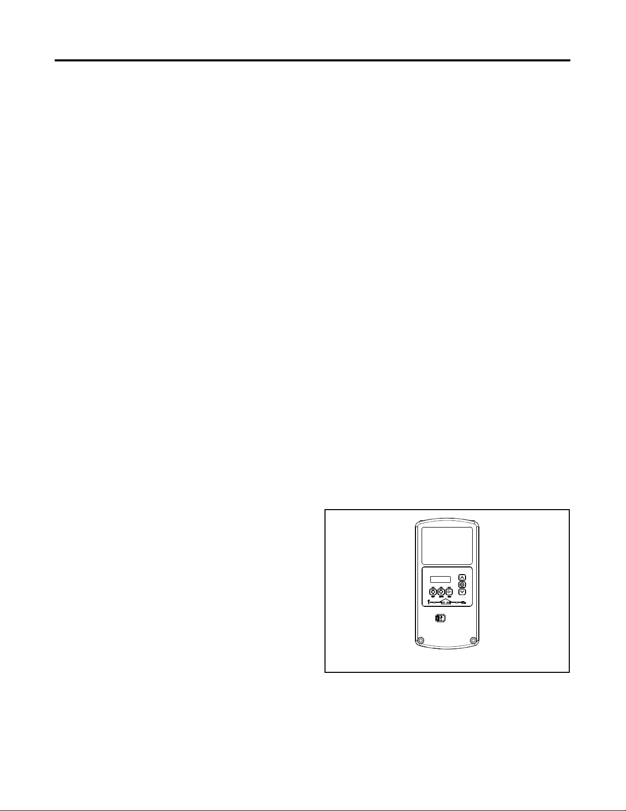
1.6 Controller
RCA and RCAL models are equipped with the RDC2 controller. See Figure 5.
The controller provides integrated control for the generator set, Kohler
®
Model RXT transfer switch, programmable interface
module (PIM) and load management devices.
The controller’s 2-line LCD screen displays status messages and system settings that are clear and easy to read, even in direct
sunlight or low light.
Figure 5 RDC2 Generator Set Controller
RDC2 Controller Features
• Six-button keypad
o OFF, AUTO, and RUN pushbuttons
o Select and arrow buttons for access to system configuration and adjustment menus
• LED indicators for OFF, AUTO, and RUN modes
• LED indicators for utility power and generator set source availability and ATS position (Model RXT transfer switch
required)
• LCD display
o Two lines x 16 characters per line
o Backlit display with adjustable contrast for excellent visibility in all lighting conditions
• Scrolling system status display
o Generator set status
o Voltage and frequency
o Engine lube oil temperature
o Oil pressure
o Battery voltage
o Engine runtime hours
• Date and time displays
• Smart engine cooldown senses engine temperature
• Digital isochronous governor to maintain steady-state speed at all loads
TP-7092 9/23 19
• Digital voltage regulation: ±0.5% RMS no-load to full-load
• Automatic start with programmed cranking cycle
• Programmable exerciser can be set to start automatically on any future day and time, and run every week or every two
weeks
• Exercise modes
o Unloaded cycle exercise with complete system diagnostics
o Unloaded full-speed exercise
o Loaded full-speed exercise (Model RXT ATS required)
• Front-access mini USB connector for Kohler
®
SiteTech™ connection
• Integral Ethernet connector for Kohler
®
OnCue
®
Plus Generator Management System
• Built-in battery charger
• Remote two-wire start/stop capability for connection of Model RDT or other transfer switches
• Diagnostic messages
o Displays diagnostic messages for the engine, generator, Model RXT transfer switch, programmable interface
module (PIM), and load management device
o Over 70 diagnostic messages can be displayed
• Maintenance reminders
• System settings
o System voltage, frequency, and phase
o Voltage adjustment
o Measurement system, English or metric
• ATS status (Model RXT ATS required)
o Source availability
o ATS position (normal/utility or emergency/generator)
o Source voltage and frequency
• ATS control (Model RXT ATS required)
o Source voltage and frequency settings
o Engine start time delay
o Transfer time delays
o Voltage calibration
o Fixed pickup and dropout settings
• Programmable Interface Module (PIM) status displays
o Input status (active/inactive)
o Output status (active/inactive)
• Load control menus
o Load status
o Test function
20 TP-7092 9/23
1.7 OnCue® Plus Generator Management System
The Kohler
®
OnCue
®
Plus Generator Management System is now included with the generator set. The OnCue
®
Plus System
allows monitoring and control of your generator set from your home or other location with Internet access using a computer or
mobile device. OnCue
®
Plus can be configured to send email or text message notifications in the event of a generator set fault.
You can also use Google Assistant or Amazon Alexa and your smart device to control your generator. Use voice commands to
check your generator’s status, check for active alerts, and start or stop an exercise. See the OnCue
®
Plus User Guide, TP-7006,
for simple setup instructions and voice commands.
OnCue
®
Plus Wireless is also available. OnCue
®
Plus Wireless works with the customer’s wireless Ethernet router and does not
require the installation of a network cable between the generator set and the customer’s router/modem.
1.8 Accessories
The following optional accessories are offered for the generator sets.
1.8.1 Cold Weather Package Kit
Heater kits are recommended for improved cold starting in locations where the ambient temperature drops below 0°C (32°F).
The cold weather package kit includes:
• Alternator brush cover
• Battery heater
• Breather tube heater
• Fuel regulator heater
• Oil heater
• Oil pressure sensor cover
• 3-way extension cord for power connection
The heaters require a continuous source of AC power. See the generator set Installation Manual and the installation instructions
provided with the kits for more information.
TP-7092 9/23 21
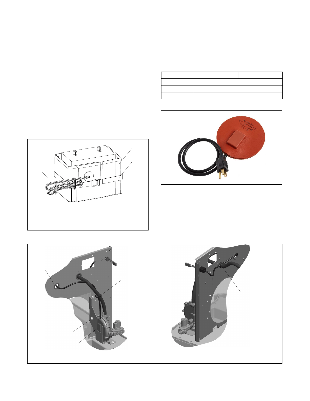
1.8.2 Battery Heater Kit
The battery heater kit contains a heating wrap to help warm the battery in cold climates. See Figure 6. The battery heater is
equipped with a thermostat that turns the heater on at 16-18°C (60-65°F) and off at 27°C (80°F). Battery heaters are
recommended for regions where the temperature regularly falls below 0°C (32°F).
Note:
Battery heaters are compatible with all Kohler-supplied lead-acid batteries. For other battery types, check the battery
manufacturer’s instructions for any restrictions regarding the use of battery heaters.
The battery heater requires a source of AC power. Verify that AC power is connected to the generator set as described in the
generator set Installation Manual. The circuit must be backed up by the generator set to provide power at all times.
Figure 6 Battery Heater (typical)
Power cord
Battery heater wrap
Retaining strap or cable ties
(included)
Power cord for 120 volt kits
Power cord for 240 volt kits
22 TP-7092 9/23
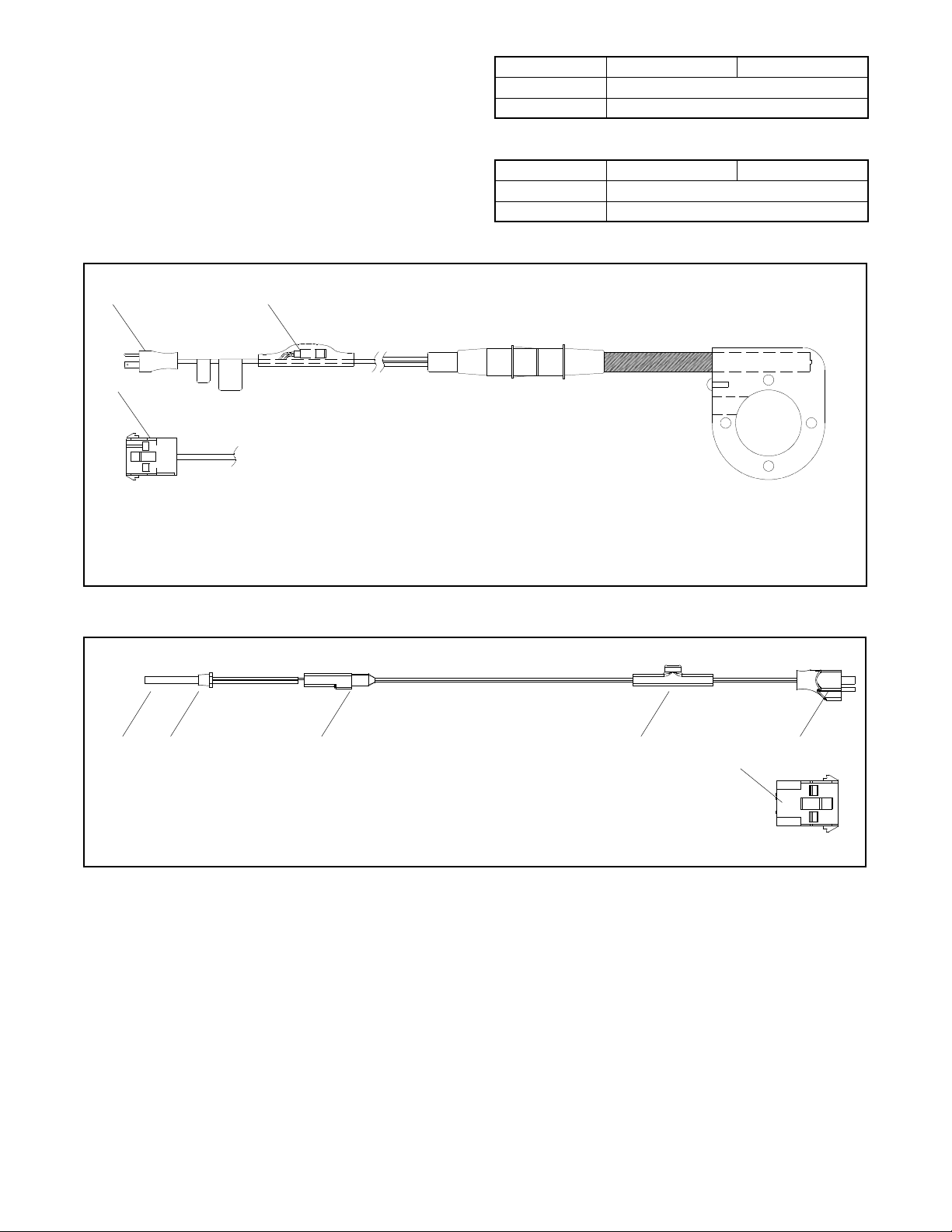
1.8.3 Breather Tube Heater and Oil Heater Kit
The breather tube heater and oil heater kit is recommended for improved cold starting in locations where the ambient temperature
drops below 0°C (32°F).
Note:
The heaters require a continuous source of AC power. See Figure 7 and Figure 8 for the power supply voltage required.
Note:
The breather tube heater and oil heater must be used together.
Verify that AC power is connected to the generator set as described in the generator set Installation Manual. The circuit must be
backed up by the generator set to provide power at all times. Refer to TT-1709 for instructions to install the heaters and connect
120VAC power.
See Figure 9 and Figure 10 for illustrations of the 120VAC breather tube heater and oil heater.
Heater Part Number
GM110893, GM110894, and GM118784
Voltage
120 VAC
Thermostat ON
4°C (40°F)
Thermostat OFF
13°C (55°F)
Figure 7 Breather Tube Heater Specifications
Heater Part Number
GM110895, GM110896, and GM118784
Voltage
120 VAC
Thermostat ON
4°C (40°F)
Thermostat OFF
13°C (55°F)
Figure 8 Oil Heater Specifications
Figure 9 Breather Tube Heater
Figure 10 Oil Heater
Heating element
Label
Thermostat
120 VAC female connector
(connect to oil heater)
120 VAC plug
Heating element
Heating probe
Thermostat
Label
120 VAC male connector (connect to breather tube heater)
GM101483
TP-7092 9/23 23
1.8.4 Fuel Regulator Heater (20 and 26 kW models only)
An optional fuel regulator heater is recommended for models 20RCA/L and 26RCA/L for improved cold starting in locations
where the ambient temperature drops below -18°C (0°F). The heater requires a continuous source of AC power.
Heater rating
120 VAC, 60 W
240 VAC, 100 W
Thermostat
4°C/13°C (40°F/55°F) Snap action
Pad diameter
127 mm (5 in.)
Cord length
914 mm (36 in.)
Figure 11 Regulator Heater Kit Specifications
Figure 12 Fuel Regulator Heater Pad
Figure 13 Fuel Regulator Heater Installation, 20RCA/L and 26RCA/L
20 kW Model
26 kW Model
GM79142
Bushing
Cable ties
Note:
Place spacer between regulator and mounting bracket
Screw, spacer, and
existing nut
Heater, fuel regulator
pad
Cable ties
GM79141H
24 TP-7092 9/23
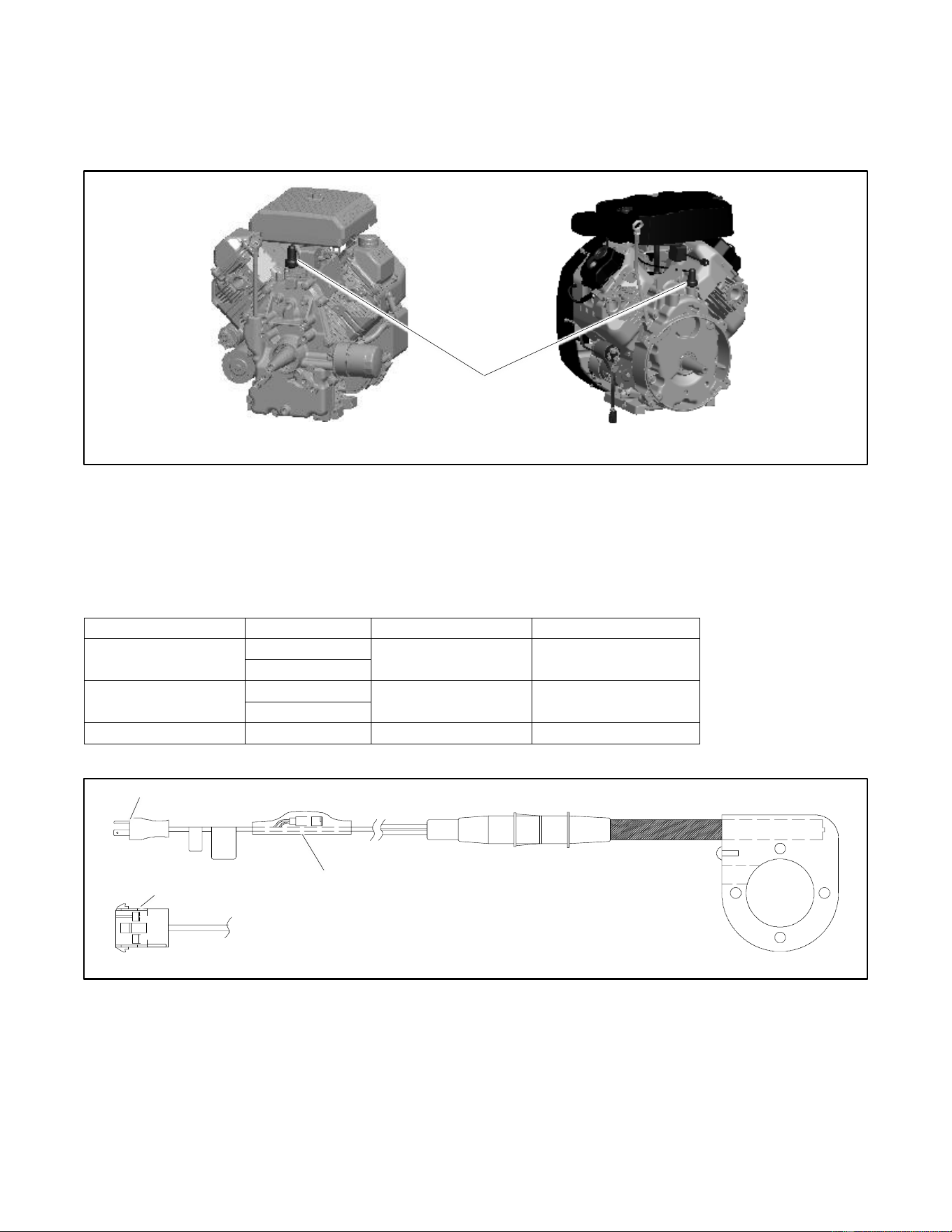
1.8.5 Oil Pressure Sensor Boot Kit
The oil pressure sensor boot protects the oil pressure sensor and its connection from moisture and frost buildup that can cause
false low oil level faults. Install the oil pressure sensor boot in locations where the ambient temperature drops below 0°C (32°F).
See Figure 14 for illustrations of the installed kit. Follow the instructions provided with the kit to install the boot.
Figure 14 Oil Pressure Sensor Boot Location
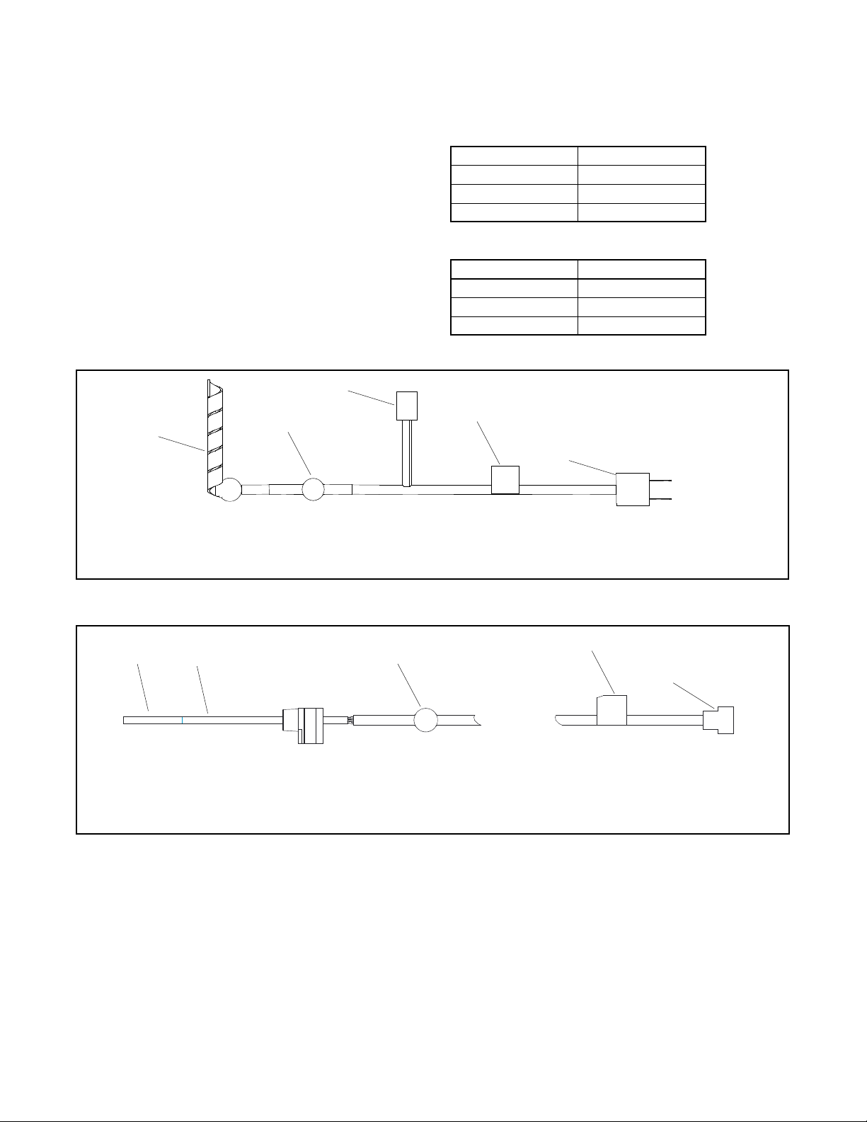
1.8.6 Carburetor Heater
An optional carburetor heater is recommended for improved cold starting in locations where the ambient temperature drops
below 0°C (32°F). The carburetor heater prevents condensation and carburetor icing. The heater requires a continuous source
of AC power.
See the generator set Installation manual for more information.
Generator set model
Voltage
Thermostat ON
Thermostat OFF
14 kW Models
120 VAC
4 ± 3°C (40 ± 5°F)
16 ± 3°C (60 ± 5°F)
240 VAC
20 kW Models
120 VAC
4 ± 4°C (40 ± 7°F)
16 ± 3°C (60 ± 5°F)
240 VAC
26 kW Models
120 VAC
4 ± 4°C (40 ± 7°F)
16 ± 3°C (60 ± 5°F)
Figure 15 Heater Specifications
Figure 16 Carburetor Heater with Thermostat and Power Connectors, 14 kW Models
Oil pressure sensor boot
14 kW Models
GM102176
20 and 26 kW Models
Thermostat
120 VAC plug
GM19463
240 VAC 3-pin Mate-N-Lock
connector
TP-7092 9/23 25
Figure 17 Carburetor Heater, 20 and 26 kW Models
1.8.7 Emergency Stop Kit
An emergency stop button is available as a loose kit. Pressing the emergency stop button causes the generator set to shut down
immediately. The generator controller displays an emergency stop shutdown message after the button is pressed.
E-stop assembly harness contains the E-stop, contact block, and two leads connected to the contact block. The harness is
factory-assembled. The kit also includes the emergency stop switch decal.
The generator set enclosure is designed with an opening for the emergency stop button. Install the emergency stop button as
described in the TT-1613 and TT-1795 instructions.
RDC2 firmware to version 5.5 or higher is required for E-stop operation. Use a personal computer (laptop) and Kohler
®
SiteTech™ software or the USB Utility to update the controller firmware, if necessary. See TP-6701, SiteTech Operation Manual,
or TT-1636, Firmware Update Using the USB Utility, for instructions if necessary.
1.8.8 Load Management
Two optional load management devices are available for use with single-phase generator sets and a model RXT or RDT transfer
switch.
• The optional Load Shed Kit mounts inside a model RDT or RXT transfer switch.
• The combined interface/ load management board is available for the Model RXT transfer switch.
The devices provide an automatic load management system designed to comply with applicable NEC requirements (ref. article
702 for Optional Standby Systems). The installer is responsible for ensuring that the power system installation complies with all
applicable state and local codes.
Note:
The load management devices are only compatible with single-phase generator sets.
The load management device automatically manages up to six residential loads. Two relays are provided to control two
independent air conditioner loads. Up to four power relay modules can be connected for management of non-essential secondary
loads.
The load management device is controlled by the RDC2 controller. The load on the generator set is monitored, and loads are
added or shed in the order of their priority. See the installation instructions provided with the load shed kit or the Model RXT
Operation and Installation Manual for more information.
Heating element
1/8 NPT threaded fitting
GM88228
Power cord disconnect plug
Thermostat
120 VAC plug
240 volt 3-pin plug
GM57968

26 TP-7092 9/23
1.8.9 PowerSync Automatic Paralleling Module (APM)
The PowerSync
®
Automatic Paralleling Module (APM) allows the use of two Model 14RCA/L or two 20RCA/L generator sets in
a single-phase paralleling system to supply power to one building or site. See Figure 18.
The APM provides a common connection point for paralleling generators and permits individual control of the generator
connections, allowing for synchronization, redundancy, and generator management.
Automatic paralleling requires:
1. Two single-phase generator sets. The generator sets must be the same size (kW) and model.
2. APM RDC2.4 paralleling firmware for the blue-board controller on each generator set. Download the latest version of
paralleling firmware from the Service Support section of the Kohler Power Resource Center (KPRC).
3. One Model RXT automatic transfer switch (ATS).
4. One Automatic Paralleling Module (APM) kit.
5. A personal computer (laptop) with Kohler
®
SiteTech™ software is required for system setup.
6. A load management device is required if one generator set cannot support the maximum total load. The load
management device (load shed kit or RXT combined interface/ load management board) is necessary in order to shed
non-critical loads in the event that one generator set shuts down and the other generator set cannot support all of the
loads.
See TT-1596, provided with the APM, for complete installation instructions. The APM and associated equipment must be
installed by a Kohler
®
trained and authorized dealer.
If the APM is not installed within sight of the generator sets, local codes may require the installation of circuit breakers near the
APM. Circuit breaker kits are available for installation inside the APM enclosure. See TT-1596 for the circuit breaker kit numbers.
Figure 18 PowerSync
®
Automatic Paralleling Module
1.8.10 Programmable Interface Module (PIM)
The optional Programmable Interface Module (PIM) provides two programmable inputs and six programmable dry contact
outputs for connection to customer-supplied equipment. The outputs are controlled by the RDC2 controller, and can also be
controlled remotely using the OnCue
®
Plus program.
The PIM is mounted in a NEMA 3R aluminum enclosure, which can be mounted indoors or outdoors. See the installation
instructions provided with the PIM.
zab26291

TP-7092 9/23 27
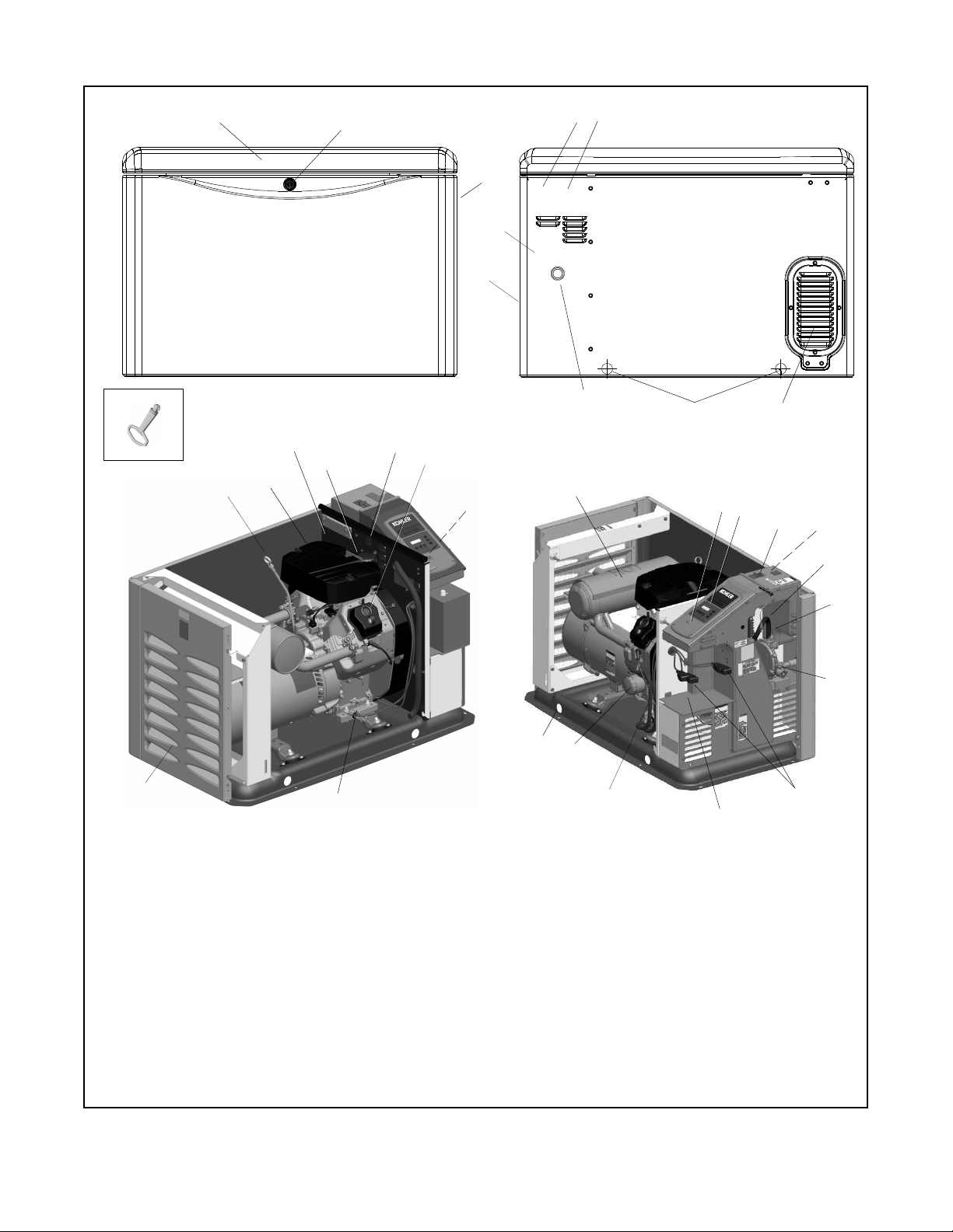
1.9 Service Views
1. Hinged roof
17. Oil fill
2. Lock
18. AC receptacle for accessories
3. Air intake
19. Oil drain valve
4. Enclosure key, provided with generator set
20. Exhaust outlet
5. High voltage electrical in
21. Silencer
6. Optional emergency stop button location
22. USB connector (for firmware updates)
7. Lifting holes
23. RDC2 controller
8. Fuel inlet
24. Line circuit breaker
9. Air intake
25. Field-connection terminal block (behind panel)
10. Low voltage electrical in
26. Digital spark advance ignition (DSAI) lead location (14RCA/L only)
11. Oil pressure switch
27. Thermostat location
12. Oil check (dipstick)
28. Fuel system
13. Air cleaner
29. Battery cables (provided)
14. Nameplate location
30. Engine starting battery location (battery purchased separately)
15. Oil filter (20 kW models)
31. Oil drain hose (shown in storage position)
16. Auxiliary winding circuit breaker
32. Oil filter (14 kW models)
Figure 19 Service Views (20 kW model shown)
ENCLOSURE PANELS
REMOVED TO SHOW DETAIL
2
3
5
6
10
9
8
3
7
4
12
13
14
15
16
17
19
20
18
21
22
23
24
25
28
26
27
29
30
7
32
31
ADV9746
1
11

28 TP-7092 9/23
1. Hinged roof
17. AC receptacles for accessories (not shown)
2. Lock
18. Oil fill
3. Air intake
19. Three-pin connectors for accessories
4. Enclosure key, provided with generator set
20. Oil level switch
5. Optional emergency stop button location
21. Oil drain valve
6. High voltage electrical in
22. Exhaust outlet
7. Low voltage electrical in
23. Silencer
8. Air intake
24. USB connector (for firmware updates)
9. Fuel inlet
25. RDC2 controller
10. Lifting holes
26. Line circuit breaker
11. Oil check (dipstick)
27. Field-connection terminal block
12. Oil filter (26 kW models)
28. Fuel system
13. Oil pressure switch
29. Battery cables (provided)
14. Air cleaner
30. Engine starting battery location (battery purchased separately)
15. Auxiliary winding circuit breaker
31. Oil drain hose (shown in storage position)
16. Engine shutdown switch
ENCLOSURE PANELS REMOVED TO SHOW DETAIL
2
3
6
5
10
8
9
3
10
4
12
1
13
14
12
15
18
21
22
187
23
24
25
26
28
27
29
30
10
31
ADV9919
1
16
19
19
13
2
20
19
Figure 20 Service Views (26 kW model shown)
TP-7092 9/23 29
Section 2. Generator Set Operation
2.1 Prestart Checklist
To ensure continued satisfactory operation, perform the following checks or inspections before or at each startup, as designated,
and at the intervals specified in the service schedule. In addition, some checks require verification after the unit starts.
Air Cleaner. Check for a clean and installed air cleaner element to prevent unfiltered air from entering the engine.
Air Inlets. Check for clean and unobstructed air inlets.
Battery. Check for tight battery connections. Consult the battery manufacturer’s instructions regarding battery care and
maintenance.
Exhaust System. Check for exhaust leaks and blockages. Check the muffler condition.
• Inspect the exhaust system components for cracks, leaks, and corrosion. Check for tight exhaust system connections.
• Check for corroded or broken metal parts and replace them as needed.
• Check that the exhaust outlet is unobstructed.
Oil Level. Check the oil level before starting the generator set and at the intervals given in the Scheduled Maintenance section.
Maintain the oil level at or near, not over, the full mark on the dipstick.
Operating Area. Check for obstructions that could block the flow of cooling air. Keep the air intake area clean. Do not leave
rags, tools, or debris on or near the generator set.
2.2 Exercising the Generator Set
Operate the generator set without load once each week for 20 minutes. See the Exercise section for information about loaded
and unloaded exercise modes. For instructions to set the exerciser, see the Setting the Exerciser section.
2.3 Generator Set Operation
DANGER
Hazardous voltage. Moving parts.
Will cause severe injury or death.
Operate the generator set only when all guards and electrical enclosures are in place.
WARNING
Carbon monoxide.
Can cause severe nausea, fainting, or death.
The exhaust system must be leakproof and routinely inspected.
Generator set operation. Carbon monoxide can cause severe nausea, fainting, or death. Carbon monoxide is an odorless,
colorless, tasteless, nonirritating gas that can cause death if inhaled for even a short time. Avoid breathing exhaust fumes when
working on or near the generator set. Never operate the generator set inside a building. Never operate the generator set where
exhaust gas could seep inside or be drawn into a potentially occupied building through windows, air intake vents, or other
openings.

30 TP-7092 9/23
Carbon monoxide symptoms. Carbon monoxide can cause severe nausea, fainting, or death. Carbon monoxide is a
poisonous gas present in exhaust gases. Carbon monoxide is an odorless, colorless, tasteless, nonirritating gas that can cause
death if inhaled for even a short time. Carbon monoxide poisoning symptoms include but are not limited to the following:
• Light-headedness, dizziness
• Physical fatigue, weakness in joints and muscles
• Sleepiness, mental fatigue, inability to concentrate or speak clearly, blurred vision
• Stomachache, vomiting, nausea
If experiencing any of these symptoms and carbon monoxide poisoning is possible, seek fresh air immediately and remain active.
Do not sit, lie down, or fall asleep. Alert others to the possibility of carbon monoxide poisoning. Seek medical attention if the
condition of affected persons does not improve within minutes of breathing fresh air.
Carbon monoxide detectors. Carbon monoxide can cause severe nausea, fainting, or death. Install carbon monoxide
detectors on each level of any building adjacent to the generator set. Locate the detectors to adequately warn the building’s
occupants of the presence of carbon monoxide. Keep the detectors operational at all times. Periodically test and replace the
carbon monoxide detectors according to the manufacturer’s instructions.
CAUTION
Hot surfaces.
Remind family members, children, and visitors to use caution near the generator set. Generator sets connected to automatic
transfer switches will start automatically during exercise periods and power outages. Some generator components become hot
when the generator is running and remain hot for a time after the generator set shuts down.
2.3.1 Local Starting and Stopping
Start: Press the RUN button to immediately start the generator set.
Stop: Press the OFF button. The engine stops.
Run the generator set with no load for at least 2 minutes to ensure adequate engine cooldown.
2.3.2 Automatic Operation
An automatic transfer switch monitors the utility power and signals the generator set to start when utility power is lost. The ATS
then transfers the load to the generator set.
When utility power is restored, the transfer switch transfers the load back to utility, runs the generator set with no load to cool
down the engine, and then stops the generator set.
See the Automatic Operation with Model RXT Transfer Switch section and Automatic Operation with Other Transfer
Switches section for more information about automatic operation.
2.3.3 Remote Starting and Stopping
A remote switch connected to terminals 3 and 4 can be used to start and stop the generator set. Close the switch to start and
run the generator set. Open the switch to stop the generator set.
Run the generator set with no load for at least 2 minutes to ensure adequate engine cooldown.
2.3.4 Remote Emergency Stop Switch
The generator set may be connected to an optional remote emergency stop switch. See Figure 21. The remote emergency stop
switch may be mounted near the generator set or in a remote location. If the emergency stop button is activated, the controller
display will show Emerg Stop Shutdwn.

TP-7092 9/23 31
Emergency Stop Switch Operation
Press the red STOP button to shut down the generator set in an emergency.
Using the emergency stop button bypasses the engine cooldown cycle, stopping the engine immediately. The controller
emergency stop lamp lights (if equipped) and the unit shuts down. The generator set cannot be restarted until the emergency
stop switch(es) is/are reset.
Lockout/Tagout
The emergency stop button can be locked in the STOP position. Insert a lock through two openings in the yellow shroud to
prevent the stop button from being pulled out. See Figure 21. Remove the lock for normal operation.
A lock is not required in order to keep the switch activated. The switch button will stay depressed until it is pulled out by the
operator.
Resetting the Emergency Stop Switch
To reset the E-stop switch, remove the locking device and pull the button out. Reset the controller by pressing the OFF/RESET
button.
Figure 21 Emergency Stop Switch (optional)
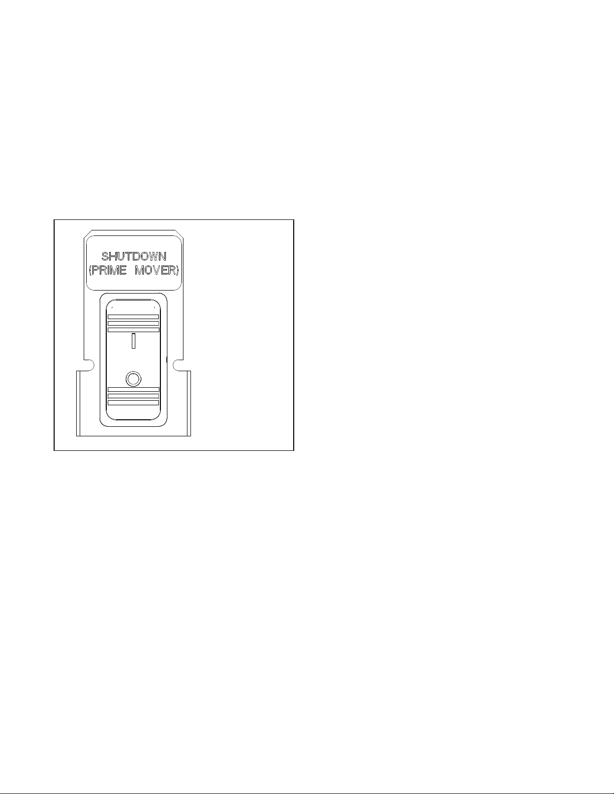
Shutdown Switch
The generator set may be equipped with a Shutdown switch. See Figure 22. This switch, also referred to as the Engine Shutdown
switch, commands an immediate shutdown and prevents an engine start if the switch is moved to the off (open, O) position.
When the shutdown switch is activated, the controller display shows Emerg Stop Shutdwn.
The switch is a mechanical, rocker-style switch. Press O to prevent engine start during generator set service. Press I to allow
the engine to start and run. See Figure 22 for switch connections.
Figure 22 Shutdown Switch
Two openings in the shroud for customer-
provided lockout/ tagout device
Stop button
GM103743
Two openings in the shroud for customer-
provided lockout/ tagout device
dwg GM111084
I = On. The engine is allowed to start.
O = OFF.
Engine shuts down, will not start.
32 TP-7092 9/23
2.3.5 Engine Start Crank Cycle
The controller attempts to start the generator set three times (three crank cycles, 15 seconds crank and 15 seconds off). If the
generator set does not start in three attempts, the system shuts down on an overcrank fault. See the Faults section.
Cranking 1, 2, and 3 are displayed during the crank cycle. Pressing the OFF button during the crank cycle stops the cranking.
No other buttons are acknowledged during the crank cycle.
20 and 26 kW Models (RDC2.4 v 1.4.4 or later)
For RDC2.4 controllers with firmware version 1.4.4 or later, the 20 and 26 kW models will perform two crank cycles with 3 starting
attempts during each cycle. The controller attempts to start the generator set three times (three starting attempts, 15 seconds
crank and 15 seconds off). If the generator set does not start in three attempts, the controller pauses for 45 seconds, and then
performs another set of 3 starting attempts. If the generator set does not start during these crank cycles, the system shuts down
on an overcrank fault. See the Faults section.
2.3.6 Engine Cooldown
The engine cooldown time delay allows the engine to run after the loads have been removed.
The engine cooldown time delay is set to 5 minutes. The engine stops before the cooldown time delay expires if the temperature
drops below the cooled-down temperature level, or if the temperature rises above the high limit during the cooldown cycle.
If a transfer switch other than the Model RXT is used, an additional engine cooldown time delay may be programmed on the
transfer switch. To allow the smart engine cooldown on the RDC2 controller to operate most efficiently, set the cooldown time
on the transfer switch controller to zero or the minimum time allowed. Refer to the instructions provided with the transfer switch
for more information.
2.3.7 Automatic Operation with Model RXT Transfer Switch
The Model RXT transfer switch connects to the RDC2 controller through the ATS interface board on the transfer switch. Also
see the Model RXT Transfer Switch Operation/Installation Manual for more information about transfer switch operation.
The controller must be in AUTO mode for automatic transfer switch operation.
Automatic Start
The RDC2 controller receives utility source voltage sensing data from the Model RXT transfer switch.
1. If the utility source voltage falls below an acceptable level, the controller starts the engine start time delay.
2. If the utility source is not restored before the time delay expires, the generator set starts.
3. After the Normal-to-Emergency time delay, the ATS is signaled to transfer the load to the emergency source.
Automatic Stop with Engine Cooldown
1. When the utility source is restored, the Emergency-to-Normal time delay starts.
2. When the Emergency-to-Normal time delay expires, the load is transferred to the utility.
3. The generator set runs through the engine cooldown cycle and then stops.
2.3.8 Automatic Operation with Other Transfer Switches
If a transfer switch other than the Model RXT (such as a Kohler Model RDT) is used, the engine start contacts from the ATS
must be connected to engine start leads 3 and 4 on the generator set.
The controller must be in AUTO mode to respond to remote start/stop signals from an ATS or remote switch. Press the AUTO
button to put the controller into automatic mode.
Automatic Start
The engine start contacts on the ATS close to signal the generator set to start, and remain closed while the generator set is
running.

TP-7092 9/23 33
Automatic Stop
The engine start contacts on the ATS open to signal the generator set to stop.
2.4 Exercise
The RDC2 controller can be set to automatically run the generator set at the same time and day each week. Weekly, bi- weekly,
or new monthly exercise is required to keep the engine and alternator in good operating condition.
Three exercise modes are available for all RCA models: unloaded cycle with system diagnostics, unloaded full speed, and
loaded full speed (requires an RXT ATS). An additional 90-second EcoExercise cycle is available for the 26RCA/L. The exercise
modes are described in more detail in the following sections. A loaded exercise can be set at the RDC2 controller only if a Model
RXT transfer switch is connected.
Note:
With transfer switches other than the Model RXT, it is possible to have two exercise settings (one unloaded exercise set at the
generator set controller, and another exercise set at the ATS controller). If the exercise times overlap, the ATS exercise setting
takes priority.
If a transfer switch other than the Model RXT is used, refer to the instructions provided with the transfer switch to set a loaded
exercise at the ATS, if desired.
2.4.1 Setting the Exerciser
When power is applied to the RDC2 controller (that is, when the battery is connected), you will be prompted to set the date and
time, select a language, and then to set the exerciser.
The first setting will flash. Press the Up and Down arrow buttons to change the setting. Press Select to save the setting and
move on to the next. See the Changing Settings section for more detailed instructions to change settings on the RDC2. See
the Setting the Exerciser section for more detailed instructions to set the exerciser or change the exercise settings.
2.4.2 Unloaded Cycle Exercise with Complete System Diagnostics
An unloaded exercise runs the generator set without signaling the transfer switch to transfer the electrical load from the utility
source to the generator set. The Unloaded Cycle exercise with diagnostics is the recommended exercise mode and is the default
exercise setting.
The Unloaded Cycle exercise runs the engine for 20 minutes in the cycle shown in Figure 23 and described below.
• Runs at reduced speed for 10 minutes to warm up and exercise the engine.
• Ramps up and runs at full speed for 3 minutes. Engine diagnostics are performed during this full-speed portion of the
cycle, which provides the best test of engine and alternator power backup capability. Diagnostic tests at full speed can
identify potential problems with the power output and alert the operator before an emergency event.
• Ramps down and runs at reduced speed for 5 minutes to cool down the engine before shutting down automatically.
Figure 23 Unloaded Exercise Cycle
3 min.
1 min.
1 min.
5 min.
10 min.
Engine Speed, RPM
Engine
Exercise
Full-Speed
Diagnostics
Cooldown

34 TP-7092 9/23
System Diagnostics
During the unloaded exercise, the controller monitors the following data. The controller display indicates that the generator set
is running, unless a fault is detected as described below.
• ATS connection. The controller verifies that the Model RXT ATS interface board is connected.
• Battery voltage. Battery voltage is checked before exercise to verify engine starting capability. Battery voltage provides
a measurement of battery health. If the controller detects low battery voltage, the condition is indicated on the display.
• Communication integrity tests. J1939, RBUS, Ethernet, and USB are monitored for messages indicating that the
controller and wiring are reliable.
• Engine speed. Engine speed is measured at reduced speed and full speed. An overspeed or underspeed condition
will result in a fault condition and shutdown.
• Generator output frequency and voltage. Operating the generator at full speed allows the RDC2 controller to check
the output power for correct voltage, frequency, and stability. When the engine is running at full speed, the controller
verifies that the voltage and frequency are within acceptable limits. A fault message is displayed if the voltage or
frequency is out of range.
• Oil pressure. Oil pressure is verified to ensure proper lubrication of critical engine components. Pressure is monitored
at both reduced and full speeds. If the oil pressure is low, the Low Oil Pressure message is displayed and the generator
set shuts down.
• Oil level sensor. The 26RCA/L model uses an oil level sensor that will shut down the engine or will not allow the engine
to start if the oil drops below a certain level.
2.4.3 EcoExercise (26RCA/L only)
A new 90 second EcoExercise cycle is available for the 26RCA/L model only. Its main features are:
• Lowers the fuel cost.
• In cold temperatures, limits condensation build- up in the crankcase.
The EcoExercise Cycle runs for 60 seconds at 3600 RPM with active diagnostics, and 30 seconds at reduced speed. Monthly
EcoExercise cycles are recommended for cold climates.
2.4.4 Unloaded Full-Speed Exercise
The unloaded full-speed exercise runs the generator set at full speed for 20minutes without transferring the load.
To set an unloaded full-speed exercise, follow the procedure in the Changing the Exercise Settings section and select Exercise
Mode: Unloaded Full.
2.4.5 Loaded Full-Speed Exercise (with RXT only)
A loaded exercise starts the generator set, ramps up to full speed, and then transfers the electrical load from the utility source
to the generator set. After 20 minutes, the load is transferred back to the utility source. The engine runs without load for 5 minutes
or until cool, and then shuts down automatically.
Note:
With a loaded exercise, power to the building is lost for up to 10 seconds during load transfer.
For a loaded exercise controlled by theRDC2 controller, a Model RXT transfer switch must be connected to the generator set.
To set a loaded exercise, follow the procedure in the Changing the Exercise Settings section and select Exercise Type:
Loaded.
For a loaded exercise with a transfer switch other than a Kohler
®
Model RXT, program the exercise at the transfer switch
controller. Refer to the transfer switch operation manual for instructions.
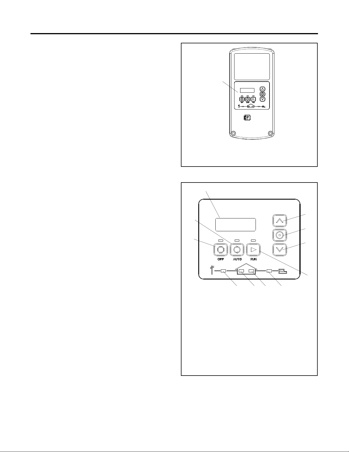
TP-7092 9/23 35
2.4.6 Shutdown During Exercise (Advanced Diagnostic)
The following advanced diagnostic operation applies to RDC2 controllers with firmware versions 5.04 and higher.
If the generator set shuts down on a fault during an exercise, the controller will try to restart the engine. If the engine starts, the
generator set will run at full speed for two minutes and then stop. The event history will show Advanced Diagnostic Active. The
exercise schedule is maintained.
If the engine does not start, the shutdown message will be displayed. Correct the fault condition and reset the fault as described
in the Faults section.
2.4.7 Power Failure During Exercise Cycle
If the utility power is lost during an unloaded exercise, the ATS transfers to the emergency source, the exercise is ended and
the control remains in the AUTO mode.
If the utility power is lost during a loaded exercise, the exercise is ended. The ATS remains in the emergency position and the
control goes into the AUTO mode.
The generator set continues to run and supply power to the load for the duration of the utility power outage. When Utility power
is restored, the ATS will re-transfer to the utility source through normal timing sequences.
2.5 Faults
The RDC2 controller displays fault messages for generator set warnings and shutdowns. Selected fault messages are shown in
the Resetting the Controller After a Fault Shutdown section. Contact an authorized dealer for service, if necessary.
2.5.1 Warnings
The controller displays a fault message but the generator set does not shut down on a warning. The controller resets
automatically after a warning condition is corrected.
2.5.2 Shutdowns
Under a fault shutdown condition, the generator set shuts down automatically and the controller displays a fault message. The
OFF LED flashes. In some cases, the engine cooldown cycle runs before the engine shuts down. See the Resetting the
Controller After a Fault Shutdown section.
Shutdown switches (such as the low oil pressure switch or low oil level (26RCA/L only) or high engine temperature switch) on
the generator set will automatically reset when the problem is corrected. However, the fault condition at the controller does not
clear until the controller is reset.
The generator set cannot be restarted until the fault condition is corrected and the controller is reset. See the Resetting The
Controller after a Fault Shutdown section for instructions to reset the controller after a fault shutdown.
2.5.3 Shutdown During Exercise (Advanced Diagnostic)
If the generator set shuts down on a fault during an exercise, the controller will try to restart the engine. If the engine starts, the
generator set will run at full speed for two minutes and then stop. The event history will show Advanced Diagnostic Active. The
exercise schedule is maintained.
If the engine does not start, the shutdown message will be displayed. Correct the fault condition and reset the fault as described
in the Faults section.
2.5.4 ATS Communication Errors
When a Model RXT transfer switch is used, an ATS fault indicates that the connection to the interface board on the transfer
switch has been lost. Check the connection to the ATS interface board.
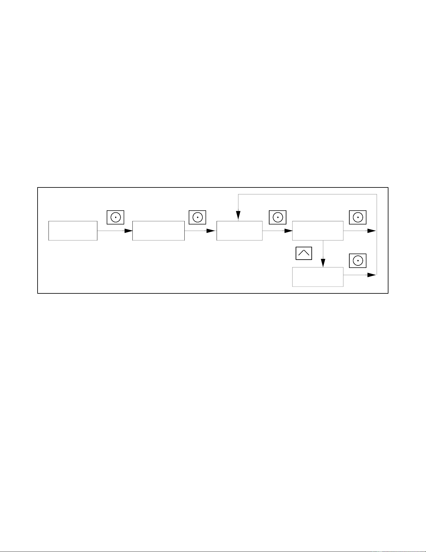
36 TP-7092 9/23
2.5.5 Resetting the Controller After a Fault Shutdown
Always identify and correct the cause of a fault shutdown before resetting the controller. Check the fault message displayed on
the controller and refer to Figure 25 to identify and correct the fault condition before proceeding. Contact an authorized dealer
for service, if necessary.
RDC2 Controller Reset Procedure
Press the OFF button to reset the controller, or follow the procedure below. See Figure 24.
1. While the fault message is displayed, press the Select button to go to the Overview menu.
2. Press Select again. The active fault message is displayed.
3. Press Select. Confirm Clear Fault: NO is displayed.
4. Press the UP arrow button. Confirm Clear Fault: YES is displayed.
5. Press the Select button to enter YES and clear the fault.
6. Press the Select button to return to the overview menu. The controller changes to OFF mode.
7. Press AUTO to put the generator set into automatic mode.
Figure 24 Clearing a Fault on the RDC2 Controller
Fault Message
Confirm Clear
Fault: NO
tp6809
Overview --->
1.2 h
Fault Message
Confirm Clear
Fault: YES
Press UP arrow button.
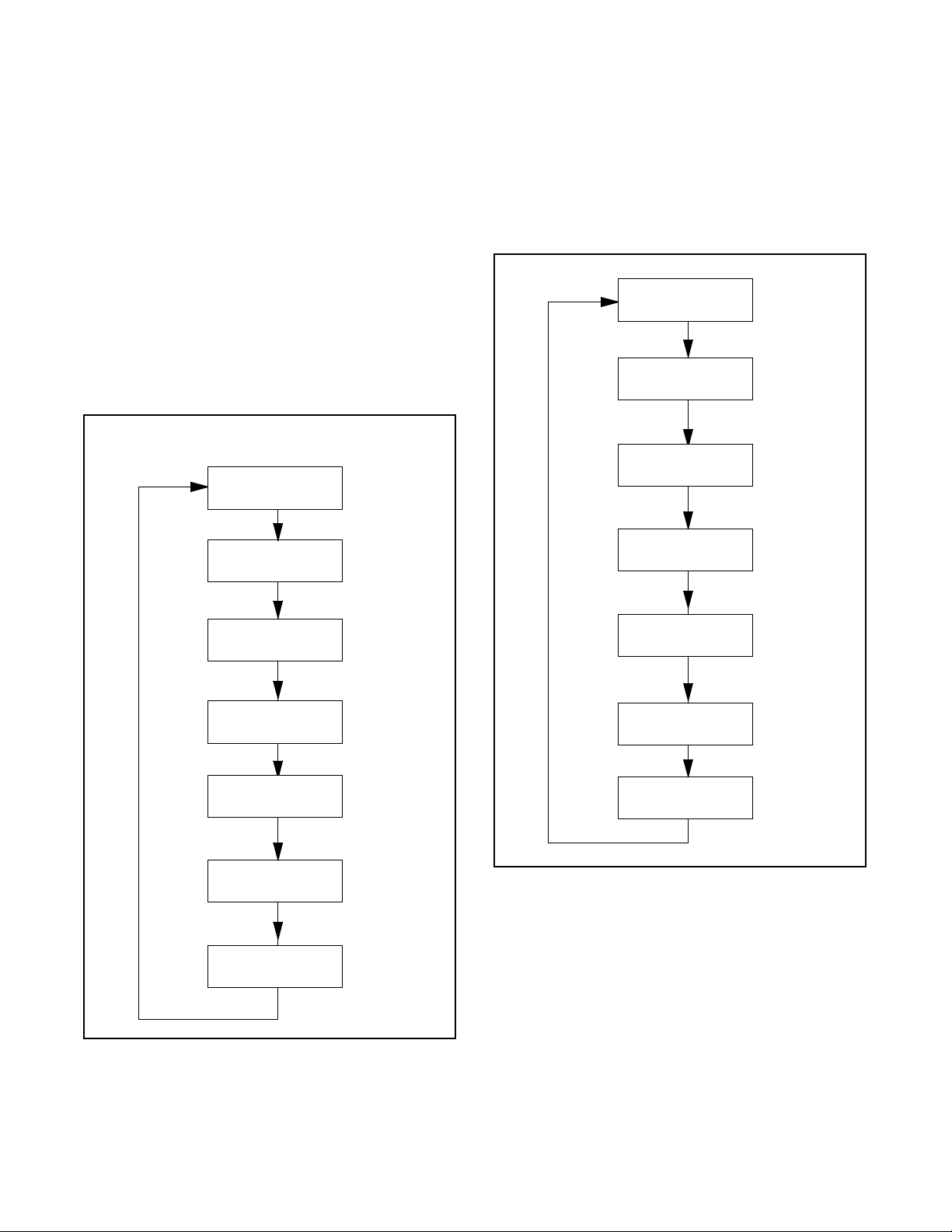
TP-7092 9/23 37
Fault Message
Warning (W) or
Shutdown (SD)
Condition
Check
AC Sens Loss
W (1 sec.)
SD (3 sec.) *
AC sensing lost. In Auto mode, generator output AC sensing
is lost. Detection begins10 seconds after crank disconnect.
Warning: after 1 second if no output detected after crank
disconnect.
Shutdown: after 3 seconds if voltage was present and then
lost.
Contact an authorized dealer
for service.
Accy PwrOver
Warning
W
Accessory Power Overload. An over current fault (short
circuit) on the accessory controller power output.
Contact an authorized dealer
for service.
Advanced
Diagnostic
SD
Shutdown during the reduced speed portion of an exercise.
The event history will show Advanced Diagnostic Active. The
engine then restarts, runs at full speed for 2 minutes, and
stops. The controller returns to AUTO mode. The exercise
schedule does not change.
If the generator set does not
restart and return to AUTO,
check for other faults that
prevent generator set
operation.
ATS ComError
W
ATS communication error. Warning is displayed if ATS
interface connection is lost. See the section title: ATS
Communication Errors.
Check communication wiring
between transfer switch
interface board and generator
set.
ATS PhaseRot
W
ATS phase rotation mismatch. Transfer switch phase rotation
does not match, ATS will not transfer.
Correct the ATS connection.
Refer to the ATS Installation
manual, wiring diagrams, and
labels on the transfer switch.
Aux Input
SD *
Auxiliary input. An optional customer-connected input is
closed. (Digital input from optional PIM.)
Check customer-supplied
equipment.
Batt Chg Flt
W
Battery charger fault. Input to PIM from an external battery
charger (not the built-in battery charger).
Check external battery charger.
Battery CrLo
Warning
W
Engine starting battery voltage falls below 11 VDC for more
than 10 seconds. Inhibited during the engine crank cycle.
Clears when the battery voltage returns to an acceptable
level.
Check the battery rating and
condition.
Check the battery charger
operation.
Charge or replace the battery.
Battery Voltage
High
W
Engine starting battery voltage rises above 16 VDC for more
than 10 seconds. Inhibited during the engine crank cycle.
Clears when the battery voltage returns to an acceptable
level.
Check the battery rating and
condition.
Check the battery charger
operation.
Battery Voltage
Low
W
Engine starting battery voltage falls below 12.5 VDC for more
than 90 seconds when the engine is not running. Not
operative during the engine crank cycle.
Clears when the battery voltage returns to an acceptable
level.
Check the battery rating and
condition.
Check the battery charger
operation.
Charge or replace the battery.
Engine Speed
High
SD *
Engine speed exceeds 115% of the normal running speed for
more than 0.3 seconds.
Contact an authorized dealer
for service.
Engine Speed
Low
SD *
Engine speed drops below 85% of the normal running speed
for more than 3 seconds.
Reduce the load.
Check enclosure thermostat
and reset if tripped. Contact an
authorized dealer for service.
Exer Not Sch
W
Exercise not scheduled. No exercise is scheduled on the
controller.
See the Setting the Exerciser
section for instructions to set
the exerciser.
Frequency High
SD *
Governed frequency exceeds 110% of the system’s
frequency setpoint for more than 10 seconds. Function
becomes active 10 seconds after engine start (10 second
inhibit).
Contact an authorized dealer
for service.
Frequency Low
SD *
Governed frequency falls below 90% of the system
frequency setting for more than 10 seconds, or 1 Hz below
the system frequency setting for more than 60 seconds.
Function becomes active 10 seconds after engine start
(10 second inhibit).
Reduce the load and restart the
generator set.
Check enclosure thermostat
and reset if tripped. Contact an
authorized
dealer for service.
Lo Crank Vlt
W
Low cranking voltage. Battery voltage dropped below 3.5
VDC during engine cranking.
Charge or replace the battery.
Locked Rotor
SD
No engine rotation is sensed during cranking. Shuts down 3
seconds after the fault is detected.
Check the battery.
Check for loose connections.
Contact an authorized dealer
for service.
MainPwrOverL
SD
Main power overload. An over current fault on the 70
controller output (short circuit).
Contact an authorized dealer
for service.

38 TP-7092 9/23
Fault Message
Warning (W) or
Shutdown (SD)
Condition
Check
Not in Auto
W
The generator set is not in Automatic (standby) mode.
Remote start and stop commands from a transfer switch or
remote switch will be ignored.
Press AUTO to place the
generator set in Automatic
mode, when appropriate.
Low Oil Level or
Oil Pressure
SD *
The oil level switch on the 26RCA indicates low oil level.
The LOP switch indicates low oil pressure for more than 5
seconds. Function becomes active 30 seconds after crank
disconnect (30 second inhibit).
Note:
The low oil pressure shutdown does not protect against low
oil level. Check the engine oil level regularly as
recommended in the Scheduled Maintenance section.
Check for leaks in the
lubrication system.
Check the oil level and add oil if
the level is low.
Check the oil level or oil
pressure switch and wiring.
If the fault persists, do not run
the generator set. Contact an
authorized dealer for service.
Over Crank
SD
Three unsuccessful starting attempts.
Check the fuel supply, spark
plug, and battery.
Check for loose connections.
Contact an authorized dealer
for service.
Spd Sens Flt
SD
Engine speed sensor has failed or engine stalled.
Contact an authorized dealer
for service.
Volts L1-L2
High
SD *
Generator voltage high. Output voltage exceeds 120% of the
system nominal voltage for more than 2 seconds.
Contact an authorized dealer
for service.
Volts L1-L2 Low
SD *
Generator voltage low. Output voltage falls below 80% of the
nominal system voltage for more than 10 seconds.
Reduce the load and restart the
generator set.
Check enclosure thermostat
and reset if tripped. Contact an
authorized dealer for service.
Engine cooldown runs before shutting down.
Figure 25 Controller Fault Messages
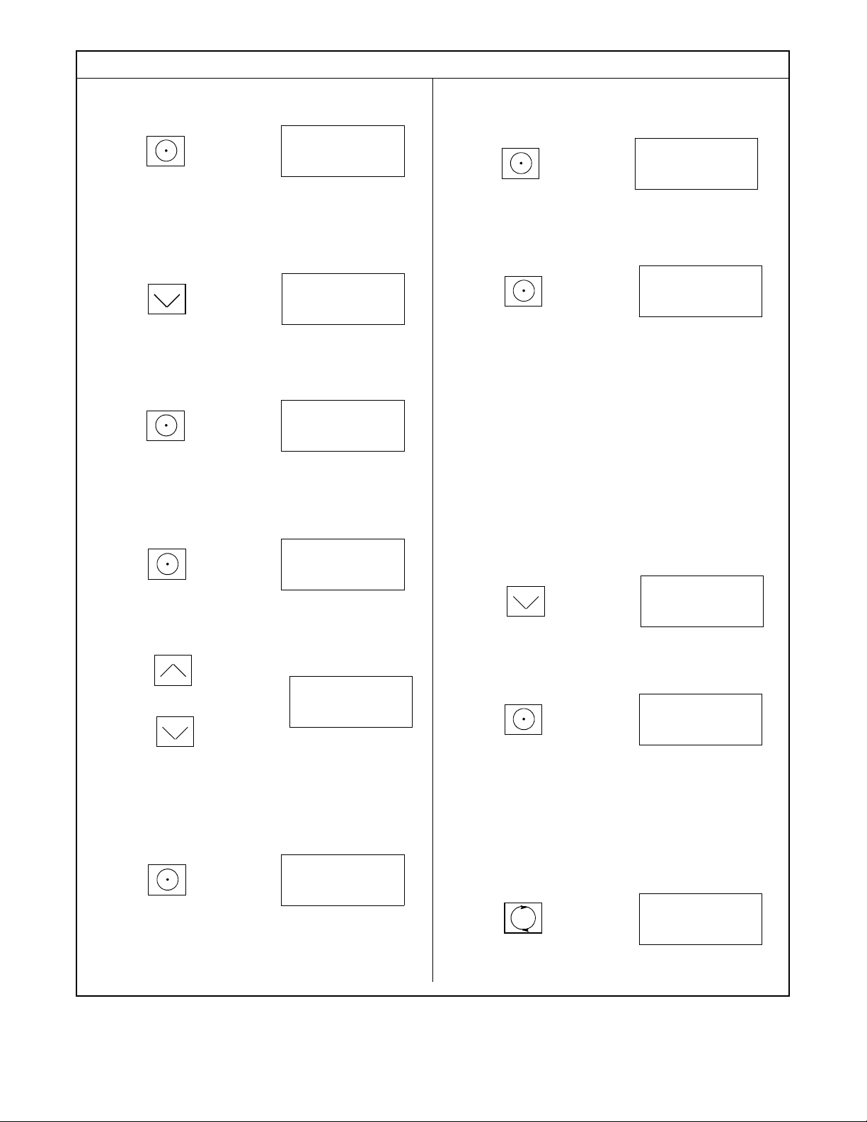
TP-7092 9/23 39
2.5.6 Faults Related to Paralleling
If the PowerSync
®
Automatic Paralleling Module (APM) is used with two 14 kw or two 20 kW generator sets, additional faults
and events related to the paralleling system may be displayed on the controller and/or in OnCue Plus. This section lists those
faults and events. See the installation instructions provided with the APM for additional paralleling information.
Note:
Contact an authorized dealer for paralleling system installation, startup, troubleshooting, or service.
Fault Text
Description
When Active
Warning Delay, sec.
Display Cleared On
Current A High Warning
Over Current
Paralleled
10
Press AUTO or OFF *
Frequency High Warning
Over Frequency
Paralleled
10
Press AUTO or OFF *
Frequency Low Warning
Under Frequency
Paralleled
10
Press AUTO or OFF *
Reactive Power Low Warning
Loss of Field
Paralleled
10
Press AUTO or OFF *
Real Power High Warning
Over Power
Paralleled
10
Press AUTO or OFF *
Real Power Low Warning
Reverse Power
Paralleled
10
Press AUTO or OFF *
Voltage L1-L2 High Warning
Over Voltage
Paralleled
10
Press AUTO or OFF *
Voltage L1-L2 Low Warning
Under Voltage
Paralleled
10
Press AUTO or OFF *
Pressing OFF will stop the generator set.
Figure 26 Warning Messages (protective relay disconnect)
Fault Text
Description
Possible Causes *
BusDeadLive
The bus is measured to be dead when one of the generators is
supposed to be supplying voltage to the bus (closed contactor)
Bus metering V9A and V9B connections to
V9 of paralleling protection harness are
connected incorrectly.
BusLiveDead
The bus is measured to be live when no generators are
connected to it (both contactors open).
Bus metering V9A and V9B connections to
V9 of paralleling protection harness
connected incorrectly.
CfgModelNum
The two generators that are intended to be paralleled have
incompatible model numbers.
Incorrect configuration of one of the
generators. Different generator types.
The paralleled generator sets must be the
same kW model. (i.e. two 14 kW or two 20
kWor 26 kW models).
CfgSysVolt
The system voltage of the two generators intended to be
paralleled is not the same. Because the system does not know
which voltage is correct, the generators will not be allowed to
start.
One of the two generators is incorrectly
configured.
Intermittent connections on RBUS network
wiring.
ChkngMeter
This generator has paralleled to the other generator and is
verifying that the metering is connected and establishing the
connection direction.
Status message appears the first time the
two generators are paralleled.
ConCheckFail
Failure to Auto-Discover APM connections.
Wires 9A and 9B crossed between the
generators.
Wires 9A or 9B not connected.
ConChecking
Performing APM connection auto-discovery.
This generator has started in RUN, the
other generator is in OFF.
ConNotDeterm
APM connection auto-discovery is not complete. This means that
the generator does not know which contactor is connected to it.
Generators not yet started in RUN with
other generator in OFF. See the APM
instruction sheet for instructions to perform
the auto-discovery procedure.
ContactorOk
Successful auto-discovery of APM connections.
Auto-discovery was activated by placing
other generator in OFF and this generator
in RUN.
ErraticSig
The power metering on this controller gives a signal that is not
consistent with the system configuration. Reversing the power
direction does not resolve the problem.
Bad wiring to the CT.
Too much tension on wires from the CT to
the controller.
LossOfComAPM
The Automatic Paralleling Module has stopped communicating on
RBUS. (An APM was detected on the RBUS network but is no
longer communicating).
APM is unplugged.
Primary controller is powered down. Check
the battery connections. See previous page
for more information.
Intermittent connections on RBUS network
wiring. Check RBUS communication
connections.

40 TP-7092 9/23
Fault Text
Description
Possible Causes *
LossOfComm2
The primary controller has lost communication with the secondary
controller. (A secondary controller was detected, then
communication was lost.)
RBUS disconnected, secondary controller
battery disconnected, updating firmware in
secondary controller, or intermittent RBUS
connections.
LossOfField
This generator has absorbed more than 25% reactive power
(magnetic excitation current) for 20 seconds.
Generator voltage on this generator is not
calibrated correctly.
Generator voltage on other generator is not
calibrated correctly.
Bus voltage on this generator is not
calibrated correctly.
Bus voltage on the other generator is not
calibrated correctly.
MeteringOk
The generator has verified that the metering is connected
correctly and that the direction is consistent with expected power
direction.
Status message indicates that the CT is
connected to the generator correctly.
MeterUnknown
This generator does not know if the metering is connected or the
orientation of the connection. This means that the generators
can’t share load accurately until this information is known.
System commissioning and startup not yet
complete. See the APM instructions.
NoCurrent
The generator has applied load (using the other generator) and
has observed no current on the power sensing inputs.
The CT is not connected to the controller.
The output leads from the generator do not
go through the CT in the correct direction.
See the APM instructions.
SyncFailure
The generator has been attempting to synchronize for over 2
minutes without success.
Generator is hunting.
Advanced speed control settings need
adjustment.
Load is changing frequently to disturb the
online generator.
For paralleling system troubleshooting and service, contact an authorized dealer.
Figure 27 Events Related to Paralleling
Generator Set State
Description
Generator Management Off
This generator has been stopped by generator management because it is not presently needed to
supply the load. The generator is available and will start if it is needed again.
Protective Relay Tripped Contactor
The contactor has been forced to open to protect one of the generators or the customer’s load.
Synchronizing
The generator is actively trying to match frequency, voltage and phase with that of the paralleling
bus.
Unloading
The generator is actively trying to transfer load from itself to the other generator.
Figure 28 Generator Set States Related to Paralleling
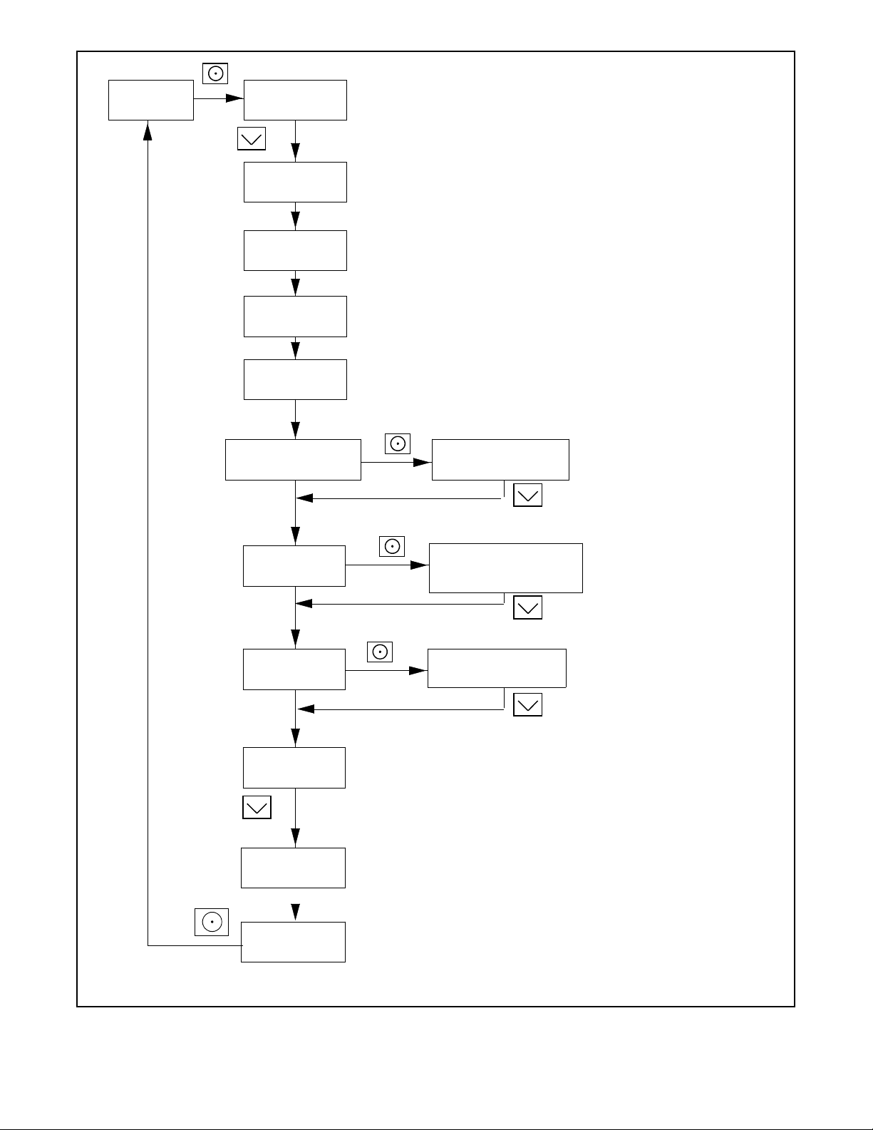
TP-7092 9/23 41
Section 3. RDC2 Controller Operation
3.1 RDC2 Generator Set/Transfer Switch Controller
Model RCA and RCAL generator sets are equipped with the RDC2 generator set/transfer switch controller.
The RDC2 controls the following power system components:
• Model RCA or RCAL generator set
• Model RXT Automatic Transfer Switch (ATS)
• Load management device
• Programmable Interface Module (PIM)
The RDC2 controller features include:
• Two-line x 16 character backlit digital display with adjustable contrast
• OFF, AUTO, and RUN generator set master control buttons
• Generator set status indicating LEDs (OFF, AUTO, RUN)
• Up, Down, and Select buttons for navigation through menus and adjustments
• Power system indicator LEDs to show utility and generator source status, and to show which source (utility or generator)
is supplying power to the load (Model RXT automatic transfer switch is required for operation of these LEDs).
3.2 Control and Indicators
Figure 29 illustrates the RDC2 controller. See Figure 30 for details of the controller’s user interface.
Figure 29 RDC2 Controls and Indicators
User interface (see Figure 30)
GM89864

42 TP-7092 9/23
Figure 30 RDC2 User Interface
3.2.1 Controller Keypad
The RUN, OFF, and AUTO buttons control the generator set as described in Figure 31.
Use the Select, Up arrow, and Down arrow buttons to navigate through the menus and change settings, if necessary. See the
Generator Set Operation section for operation instructions.
Button
Button Function
RUN
Starts the generator set. The engine start time delay is ignored.
OFF
Stops the generator set. The cooldown time delay is ignored.
During the engine crank cycle, pressing OFF will stop the crank cycle.
Press OFF to clear faults and reset the controller.
AUTO
Places the generator set in Automatic (standby) mode.
Down arrow
Use to navigate through menus and change settings. This manual contains instructions to navigate the controller menus
and adjust settings on the RDC2 controller.
Select
Up arrow
Figure 31 RDC2 Controller Pushbutton Operation
Building on generator power LED*
2-line LCD display
Up button
Select button
Down button
RUN button and LED
Generator power available LED*
Building on utility power LED*
Utility power available LED*
AUTO button and LED
OFF button and LED
GM77569
These LEDs operate only if a Model RXT automatic transfer switch is connected.
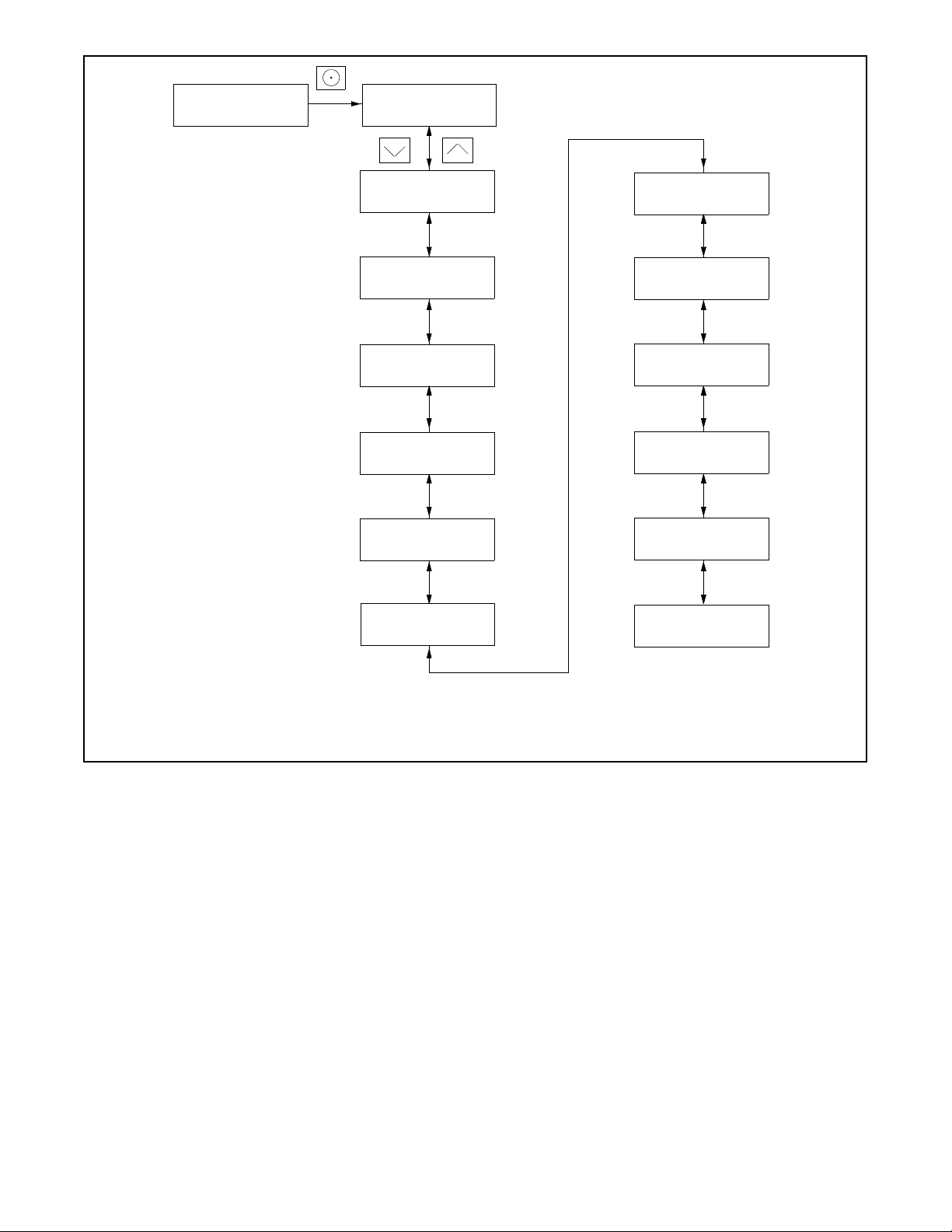
TP-7092 9/23 43
3.2.2 LED Indicators
LEDs above the RUN, OFF, and AUTO buttons indicate the mode of operation as shown in Figure 32.
Power System LEDs indicate the status of the utility power and the generator set, and indicate which source is supplying power
to the building (based on the position of the RXT transfer switch). See Figure 32.
Note:
The power system LEDs operate only if a Model RXT transfer switch is connected.
LED
LED Operation
RUN
Lights when the generator set has been started locally by pressing the RUN button. Remote start and
stop commands are ignored.
OFF
Lights for 2 seconds, then flashes every 2 seconds when the generator set and controller are off.
Remote start/stop commands have no effect. The exercise cycle will not run.
In Auto mode, OFF LED flashes quickly to indicate a fault shutdown. Attention required. Identify and
correct the fault condition before resetting the controller.
AUTO
Lights when the generator is in automatic (standby) mode. Generator set will respond to engine start and
stop commands from the controller (for example, exercise start and stop commands) or an ATS. Time
delays operate as described in the Generator Set Operation section.
Utility Power Available *
Lights when utility power is available.
Building on Utility Power *
Lights when the building load is connected to utility power through the RXT transfer switch.
Generator Power Available *
Lights when generator power is available.
Building on Generator Power *
Lights when the building load is connected to generator power through the RXT transfer switch.
These LEDs operate only if a Model RXT transfer switch is connected.
Figure 32 RDC2 Controller LED Operation
3.2.3 LCD Display
The controller is equipped with a two-line x 16-character backlit digital display with adjustable contrast. When the generator is
running, the controller automatically scrolls through the displays shown in Figure 33. When the system is in standby mode and
the controller is in AUTO, the screens shown in Figure 33 are displayed.
When a fault or warning condition exists, the controller will show the corresponding message. See the Fault section for more
information about faults.
Controller menus display power system information, including status information for the engine, generator, and optional RBUS
accessories, exercise settings, and event history. Some menus allow changes to the controller settings. See the related sections
in the manual for menu diagrams.
The display contrast is adjustable. Navigate to the Genset System menu and step down to the Contrast screen. Press the Select
button, and then use the up and down arrow buttons to adjust the contrast. See the related sections in the manual, Changing
Settings, and Genset System Menu.
The display backlight turns off after about a minute of no activity. The backlight turns on when a button is pressed or when the
generator set starts.
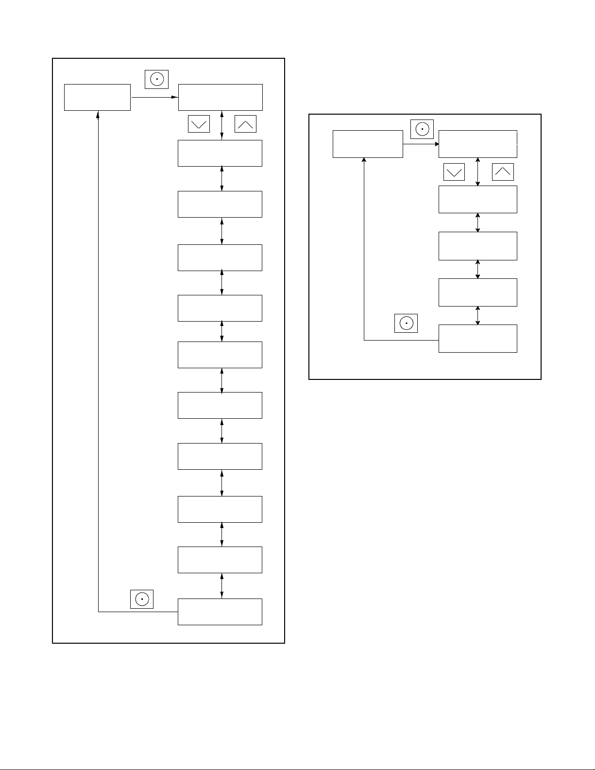
44 TP-7092 9/23
Figure 33 Autopaging Displays, Generator Running and Automatic Mode
3.3 Controller Power
The RDC2 controller is powered by the generator set engine starting battery and the built-in battery charger.
Note:
To disconnect controller power, disconnect the utility power to the generator set and disconnect the battery.
If controller power is disconnected and reconnected, you will be prompted to set the language, time, date, and exerciser. The
first setting will flash. Press the Up and Down arrow buttons to change the setting. Press Select to save the setting and move
on to the next. Repeat until all settings are saved and the controller returns to the main menu. See the Changing Settings
section for more detailed instructions to change settings on the RDC2. See the Setting the Exerciser section for more detailed
instructions to set the exerciser or change the exercise settings.
3.4 Battery Charging
The controller includes a built-in battery charger to maintain the engine starting battery. The RDC2 controller monitors the battery
voltage and provides a constant 13.4 ±2% VDC voltage and maximum 2.5 amps to charge the battery.
The installer must connect utility power provided from the building on a breaker-protected circuit for the built-in battery charger
as described in the generator Installation Manual.
Active Alert
Sample data shown.
Genset Status
Running
Voltage: 240V
Freq: 60.0 Hz
Engine: 72.0F
Oil Pressure: OK
Battery
12.3V
Engine Runtime:
24.5 h
Date: 02DEC2011
Time: HR:MNpm
Active Alert
Genset Status
Standby
Battery
12.3V
Engine Runtime:
24.5 h
Date: 02DEC2011
Time: HR:MNpm
Next Exercise:
09:00p 09Dec2011
Next Maintenance:
150 h or Mar2012
Automatic mode
Generator running
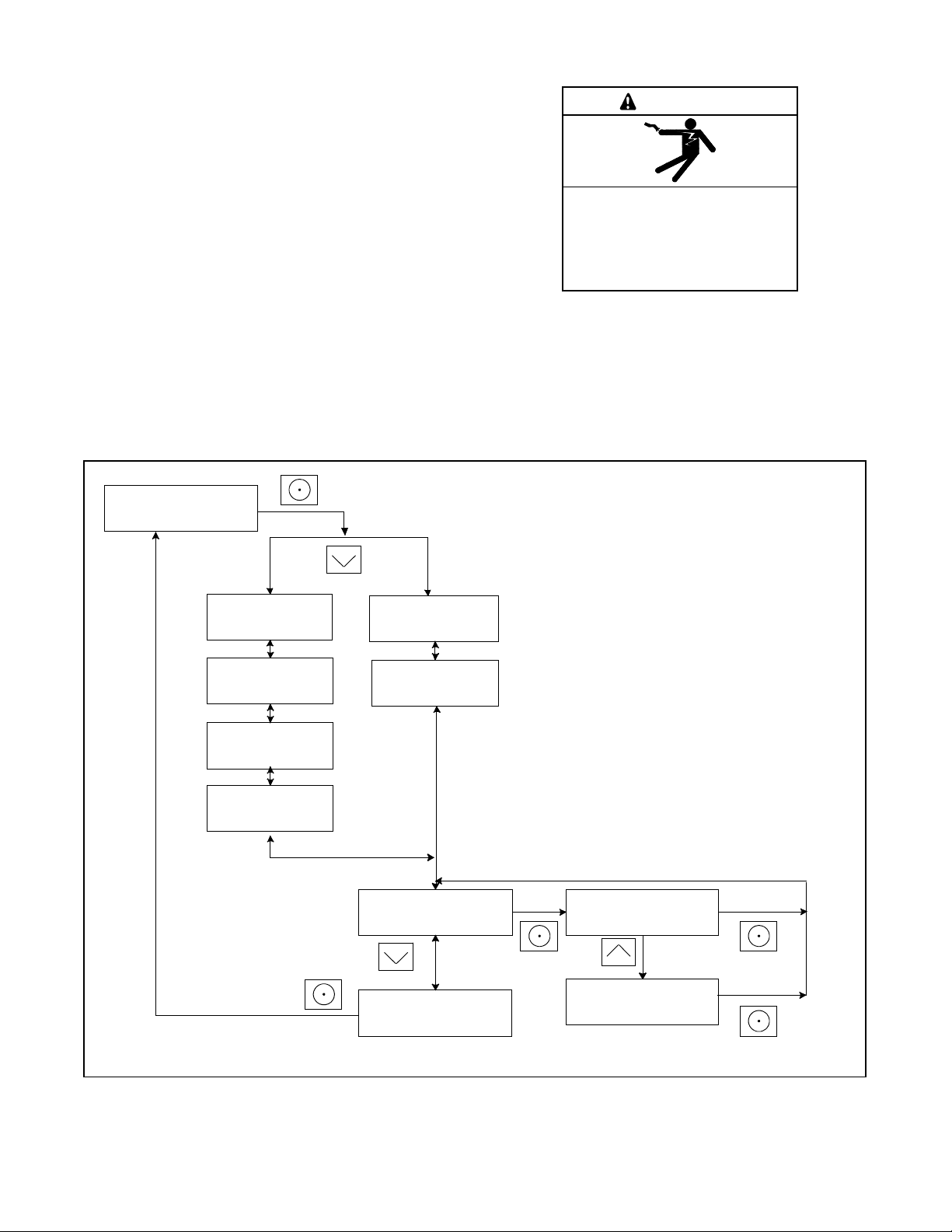
TP-7092 9/23 45
3.5 Changing Settings
Some settings can be changed from the controller keypad. The controller settings and generator set output are factory-set and
should not require field adjustment under normal circumstances. Check and adjust the settings and/or output when:
• The controller has been replaced.
• The voltage requires adjustment for a particular application.
• Troubleshooting generator set problems.
Have controller setup and adjustment performed only by an authorized dealer or authorized representative.
The following procedure explains how to change settings. See the Changing Settings section for an example using the Date
and Time settings.
Note:
Use caution when navigating the controller menus. In some menus, pressing the Select button can enable editing of the controller
settings. Changing the settings to incorrect values can adversely affect generator set operation or render the unit inoperable.
Procedure to Change Settings
1. Press the Select button to enter the main menu.
2. Press the down arrow button until the desired menu is displayed. The Genset System menu is used for this example.
See the Main Menu section.
3. Press the Select button to enter the genset system displays. See Figure 34.
4. Press the down arrow button to step through the generator set system settings.
5. To change any of the genset system settings, press the Select button. The selected setting flashes.
6. Press the up or down arrow buttons to increase or decrease the setting.
7. When the desired setting is shown, press Select. The value stops flashing. If there are additional adjustable settings
on the screen, the next setting flashes. For example, in the date menu, the day, month, and year can be adjusted.
8. Repeat steps 6 and 7 for each setting on the screen.
9. Press the down arrow to step to the next screen.
10. To exit, press the down arrow button until Return is displayed. Press the Select button to exit the menu.
11. Press the AUTO or OFF button to exit the main menu.
Note:
If no buttons are pushed, the controller exits the menus and returns to the generator set status display after 5 minutes.
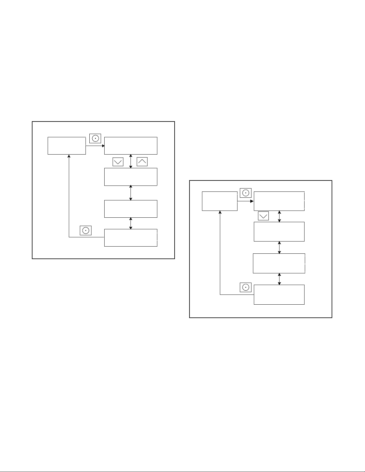
46 TP-7092 9/23
Figure 34 Changing Settings
Changing Settings on the RDC2 Controller
1. Press the Select button to enter the main menu.
8. When the correct date is shown, press the Select
button. The saved date is shown.
Press:
Press:
Display:
Display:
Press:
Display:
Press:
Display:
Press:
Display:
Press:
Display:
Press:
Display:
Press:
Display:
Press:
Display:
Press:
Display:
Press:
Display:
Overview -->
1.2 h
Date -->
and Time
Date
05Dec2011
Date
05Dec
2011
Date
05Dec
2012
Date
05
Dec2012
Date
03Jan2012
Time:
01.49pm
<-- Return
Date -->
and Time
Genset State
Standby
2. Press the down arrow button until the desired menu
is displayed. See the Main Menu
section. Date and
Time are used for this example.
3. Press the Select button to enter the Date and Time
menu.
4. To change the date and time settings, press the
Select button again. The year will flash.
5. Press the up or down arrow buttons to change the
year.
6. When the correct year is shown, press the Select
button. The year is saved and the next setting
(month) flashes.
7. Repeat steps 5 and 6, using the arrow and select
buttons to set the month and the date.
OR
9. Press the down arrow button to step to the next menu.
10. Repeat steps 5 and 6, using the arrow and select buttons
to set and save the time.
Note:
To change from am to pm, press the up arrow key to
increase the hour until the correct hour and pm is
displayed.
11.
In the time format menu, press Select and then press the
up or down arrow button to change the format, 12 hr. or
24 hr. Press Select to save the displayed format.
12. Press the down arrow button. Return is displayed.
13. Press Select to return to the Date and Time menu.
14. Press the Up or Down arrow buttons to step to a different
menu.
15. Press Auto to signal the controller to exit the menus and
return to the generator set status display.
AUTO
Note:
If no buttons are pressed, the controller returns to the status
display after 5 minutes.
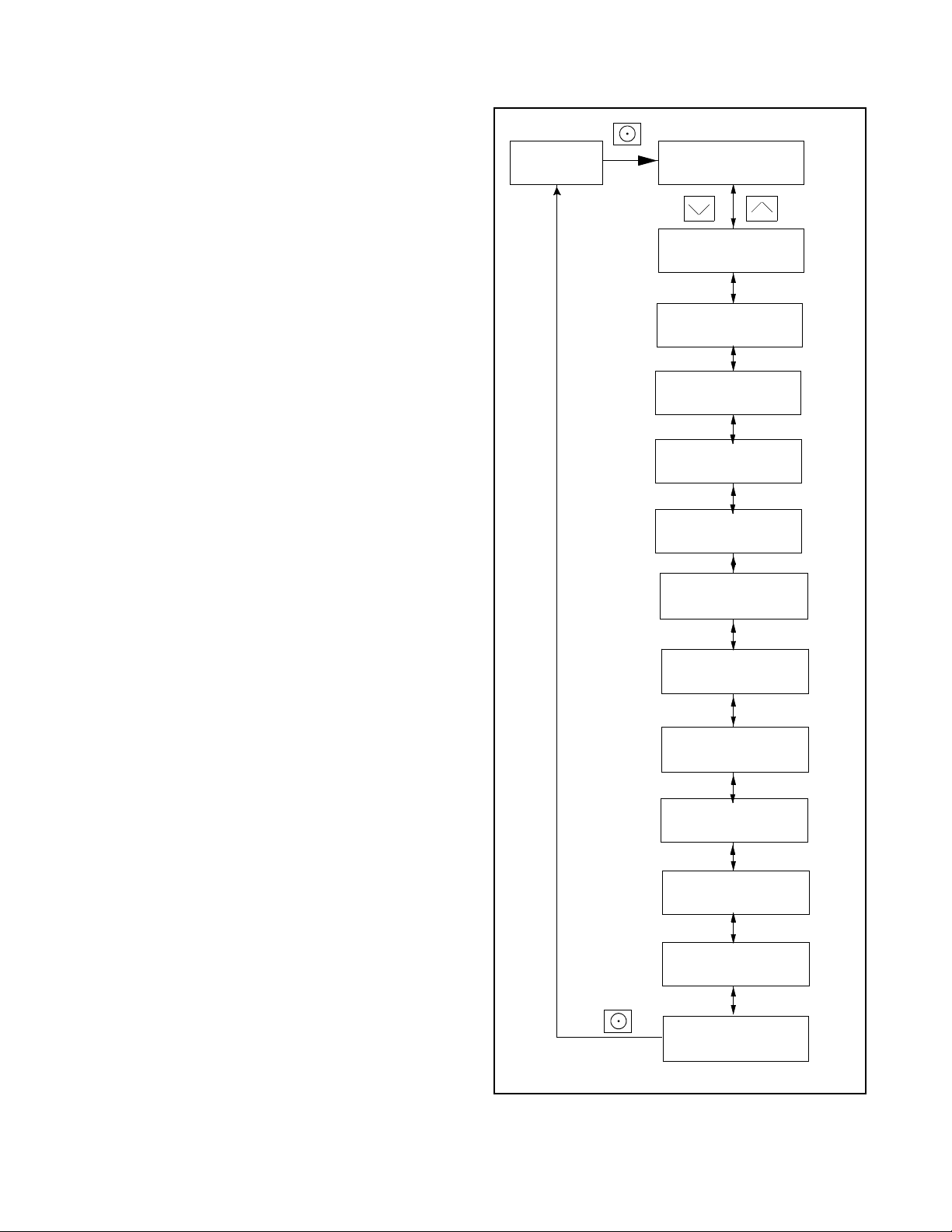
TP-7092 9/23 47
3.6 Setting the Exerciser
Set the exerciser to automatically run the generator set for 20 minutes every week or every two weeks.
3.6.1 Setting the Exerciser at Controller Power-up
When battery power is connected to the controller, you will be prompted to set the language, date and time, and then to set the
exerciser.
The first setting will flash. Press the Up and Down arrow buttons to change the setting. Press Select to save the setting and
move on to the next. See the Changing Settings section for more detailed instructions to change settings on the RDC2.
If the battery is disconnected and reconnected during generator set maintenance or service, the time, date, and exercise settings
will need to be re-entered.
3.6.2 Changing the Exercise Settings
This section explains how to change the exercise settings after the initial setup.
Follow the procedure below and see the flowchart in Figure 35 to set the exercise time and date, mode, and frequency.
Procedure to Set the Exerciser
1. Press the AUTO button on the controller.
2. Press the Select button to go to the main menu. See the Main Menu section.
3. Press the down arrow button to step to the Genset System menu.
4. Press the Select button to enter the Genset system menu. See Figure 35.
5. Use the down arrow button to step to the Next Exercise menu. If the exerciser is not set, No Exercise Scheduled will
be displayed.
6. Press and HOLD the Select button to enable editing.
7. Press the Select button. The setting flashes to show that it can be changed. For example, HR flashes to show that the
hour can be changed.
8. Press the Up or Down arrow buttons to change the setting.
9. Press the Select button to save the setting and move to the next. For example, save HR setting and move to MN.
10. Repeat steps 5 through 9 to change the next item on the line until the desired settings are displayed.
11. Press Select to save after all settings have been selected. Settings will stop flashing.
12. If the generator set is connected to a Kohler
®
Model RXT transfer switch, the exercise can be changed to a loaded
exercise. Set the Exercise Mode to Unloaded Cycle, Unloaded Full, or Loaded Full (RXT ATS required) as shown in
Figure 35. Unloaded Cycle is recommended. See the Unloaded Cycle Exercise with Complete System Diagnostic
through Loaded Full-Speed Exercise (with RXT only) sections for information about the exercise modes.
13. Set the exercise frequency (weekly or every two weeks). Weekly exercises are recommended.
14. Press the down arrow button to step to the Return menu. Press the Select button to return to the main menu.
After a scheduled exercise run, the next exercise time and date will be updated automatically based on the Exercise Frequency
setting.
Other transfer switches: For a loaded exercise with a transfer switch other than a Kohler
®
Model RXT ATS, refer to the transfer
switch operation manual for instructions.
Exerciser Reset
To reset the exerciser to run at a different day and/or time or to change the exercise mode, follow the procedure in Changing
the Exercise Settings section to change the exerciser settings.
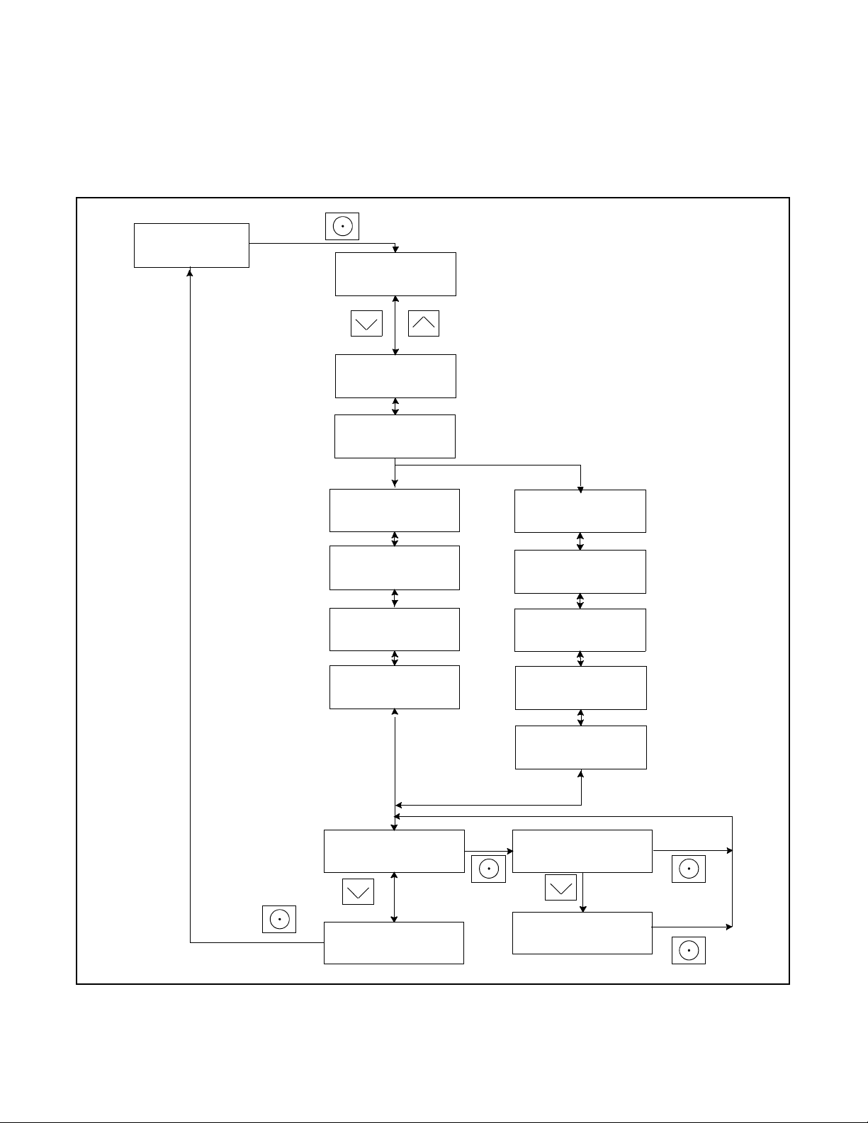
48 TP-7092 9/23
Figure 35 Procedure to Set the Exerciser on the RDC2 Controller
Genset - - >
System
Next Exercise
HR:MN PM MM/DD/YY
If the exerciser has not been set, No Exercise Sch will be displayed.
tp6804
Exercise Mode:
Unloaded Cycle/Unloaded
Full/ Loaded Full
Exercise Freq:
Weekly/Bi-Weekly
System Freq:
XX.X Hz
System Phase
System Volt
System Battery
Fuel Type
Next Exercise *
HR:MN PM MM/DD/YY
HOLD:
HOLD:
HOLD:
Exercise Mode:
Loaded
Exercise Freq:
Weekly
Language:
Contrast:
50
<- - Return
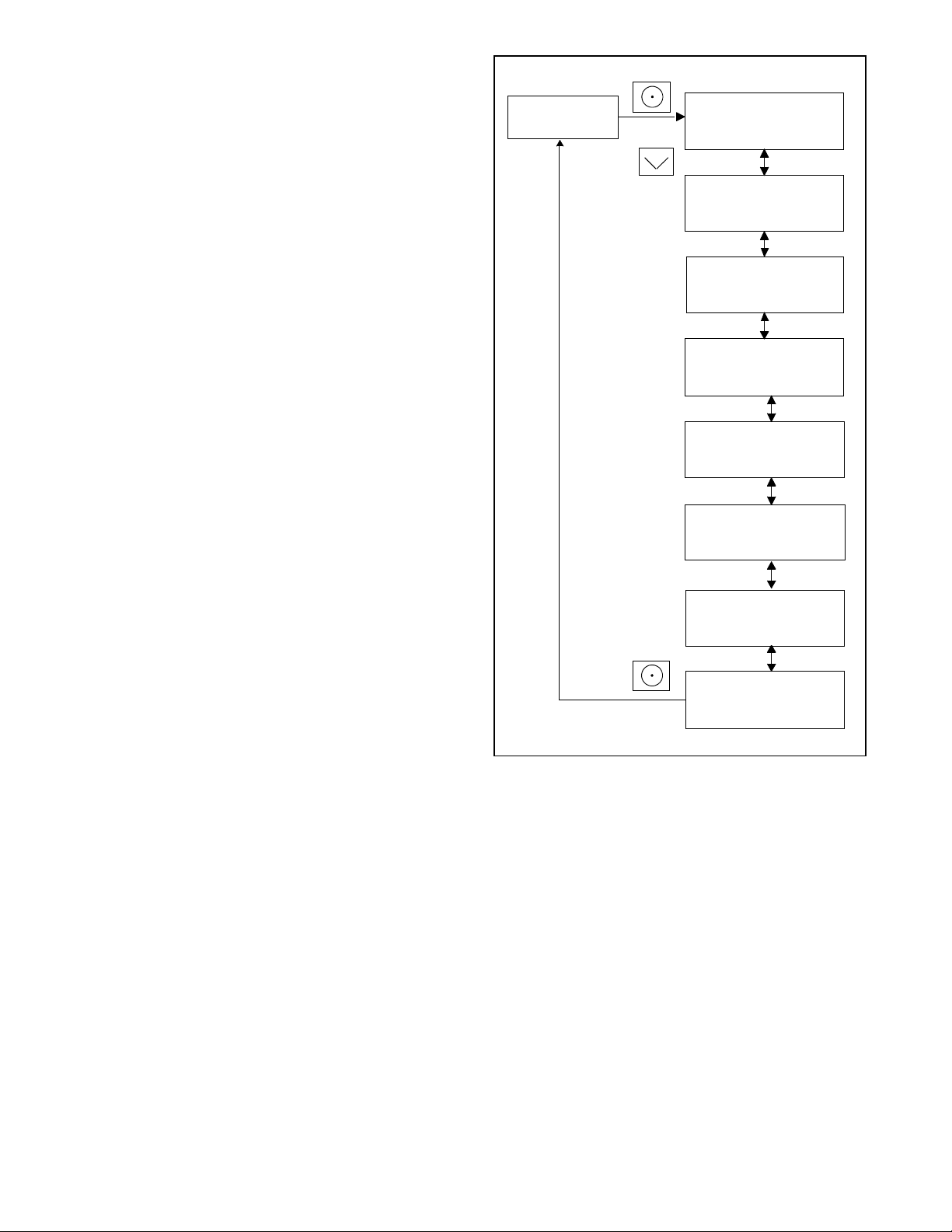
TP-7092 9/23 49
3.7 RDC2 Controller Menus
Controller menus display power system information, including status information for the engine, generator, and optional RBUS
accessories, exercise settings, and event history. Some menus allow changes to the controller settings. Status information,
including the engine runtime, cannot be changed by the operator.
Diagrams in the following sections show how to navigate through the menus. The diagrams show sample settings. Settings for
your application may vary.
Note:
Use caution when navigating the controller menus. In some menus, pressing the Select button can enable editing of the controller
settings. Changing the settings to incorrect values can adversely affect generator set operation or render the unit inoperable.
If a setting on the controller display is flashing, edit mode has been enabled. Press the OFF or AUTO button to exit the edit
mode.
3.8 Main Menu
Press the Select button once to bring up the main menu. Overview is displayed. See Figure 36. Press the down arrow button to
step to the next menu, Engine Metering. Use the UP and DOWN arrow buttons to step up and down through the menus shown
in Figure 36.
The controller will exit the main menu after 5 minutes if no buttons are pressed. To exit the main menu immediately, press the
controller’s OFF or AUTO button.
Figure 36 RDC2 Main Menu
Status
Displays
Press the Up and Down arrow buttons to
move between menus.
Press OFF or AUTO to exit the menus.
Overview --->
1.2 h
Engine --->
Metering
Generator --->
Metering
Genset --->
Information
Genset --->
Run Time
Genset --->
System
Date --->
and Time
Network --->
Information
PIM --->
Status †
Load --->
Control ‡
ATS Configuration appears only if a Model RXT transfer switch is connected.
†
PIM Status appears only if a programmable interface module is connected.
‡ Load Control appears only if a load management device is connected.
ATS --->
Status
ATS --->
Configuration *
Event Log --->
tp6804
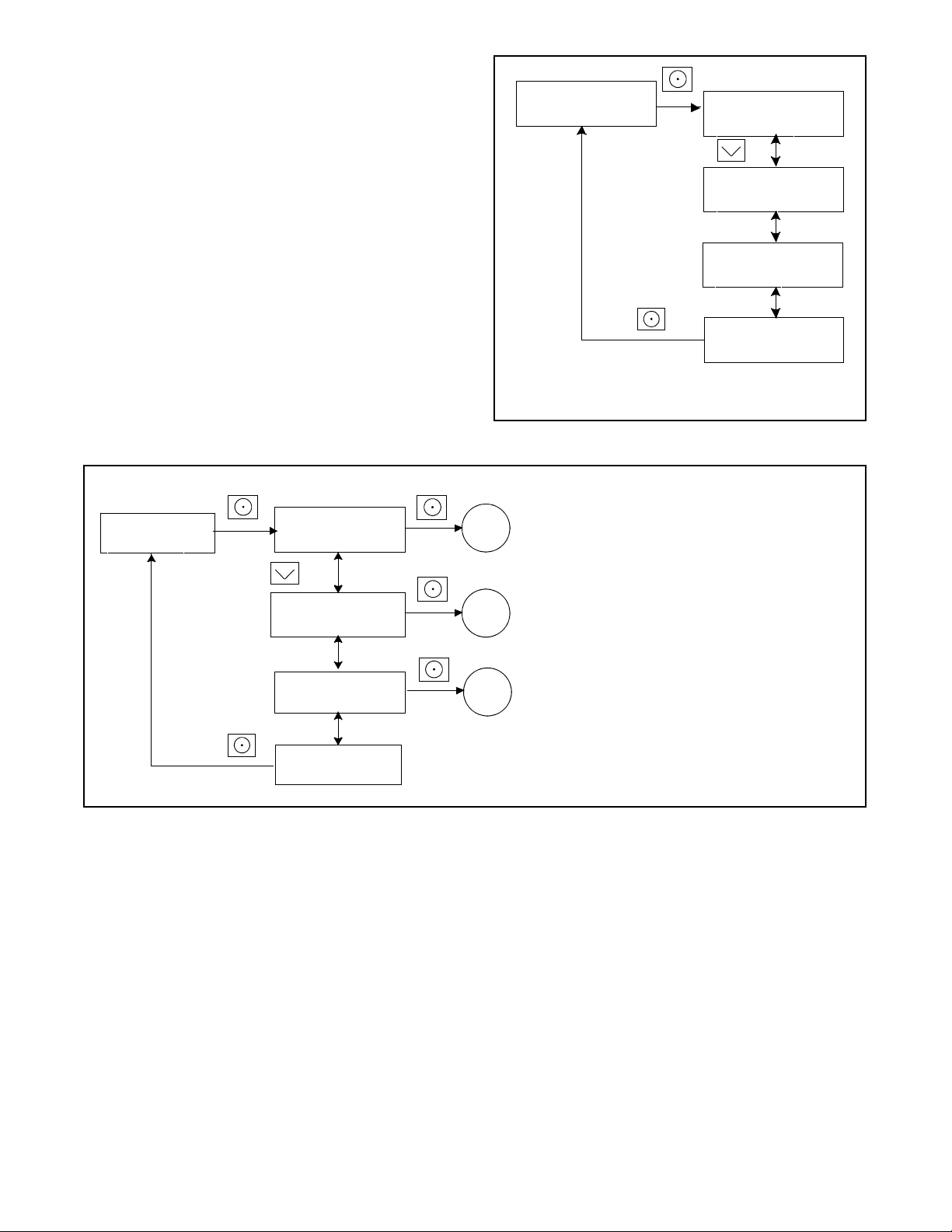
50 TP-7092 9/23
3.9 Overview Menu
Figure 37 Overview Menu
Overview --->
1.2 h
Active Alert (if any)
Genset Status
Standby
Voltage: 240V
Freq: 60.0 Hz
Engine: 72F
Oil Pressure: OK
Battery:
12.0V
Engine Runtime:
24.5 h
Date: 02DEC2011
Time: HR:MNpm
Next Exercise:
09:00p 09Dec2011
Next Maintenance:
150 h or Mar2012
SW Version:
4.07
<--- Return
Tp6804
Note:
Actual settings may vary.
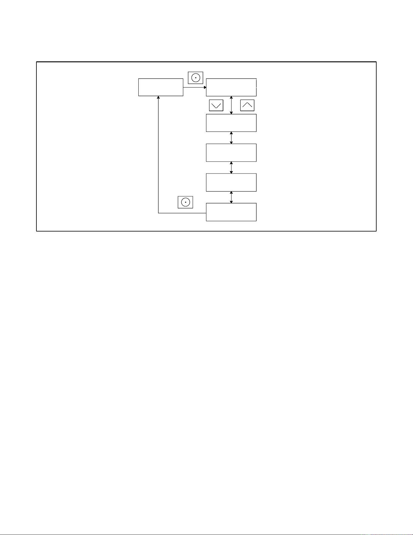
TP-7092 9/23 51
3.10 Engine Metering Menu
The engine metering menu displays engine status information as shown in Figure 38. This menu displays status information
only. No settings can be changed from this menu.
Figure 38 Engine Metering Menu
Engine --->
Metering
<--- Return
Eng Speed:
3600 RPM
Oil Pressure:
Switch: OK
Oil Temperature:
72.0 F
Battery:
12.0 V
tp6810
Note:
Actual settings may vary.

52 TP-7092 9/23
3.11 Generator Metering Menu
The generator metering menu displays the generator voltage and frequency. See the figure titled: Generator Metering Menu.
DANGER
Hazardous voltage.
Will cause severe injury or death.
This equipment must be installed and serviced by qualified electrical personnel.
Voltage Calibration
The voltage calibration mode can be entered from the Generator Metering menu. Contact a Kohler-authorized dealer for service.
The Reset Calibration menu allows you to set the voltage reading back to the original value after calibration, if necessary.
See Figure 39.
Figure 39 Generator Metering Menu
Generator -->
Metering
Volts L1- L2:
240 V
Volts:
240 V
Reset
Calibration
Reset
Calib? No
Reset
Calib? Yes
<--- Return
tp6810
Note:
Actual settings may vary.
Frequency:
60.0 Hz
Frequency:
60.0 Hz
Volts L2- L3:
240 V
Volts L3- L1:
240 V
Three-phase
Single-phase
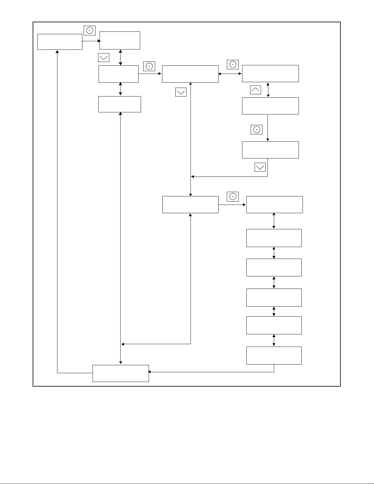
TP-7092 9/23 53
3.12 Generator Set Information Menu
The generator set model number and serial numbers are displayed (see Figure 40). No changes are allowed from this menu.
Model and serial numbers are factory-set and should not require changes in the field, except in the event that the controller is
being replaced. A personal computer running Kohler
®
SiteTech™ software is required to enter the generator set model number
and serial numbers on a replacement controller. Contact an authorized Kohler dealer for service.
Figure 40 Generator Set Information Menu
3.13 Genset Run Time Menu
The data shown in Figure 41 are displayed. No changes are allowed from this menu.
Eng Runtime displays the total number of hours that the generator set engine has run. The runtime is not resettable.
The Next Maintenance menu shows the number of hours of generator set operation until maintenance is required. The estimated
date for the next scheduled maintenance is also displayed. The maintenance reminder intervals are based on the engine
manufacturer’s recommendation for changing the oil. Refer to the Scheduled Maintenance section, for maintenance instructions.
After changing the oil and performing other recommended maintenance, go to the Overview menu to reset the maintenance
timer. See the Resetting the Maintenance Timer section for instructions to reset the maintenance timer.
Figure 41 Generator Set Run Time Menu
Genset ---->
Information
<---- Return
Genset M/N:
20RCA
Genset S/N:
########
Controller S/N:
########
tp6804
Genset ---->
Run Time
Eng Runtime:
24.5 h
Eng Starts:
18
Next Maintenance:
150 h or Mar2014
<---- Return
tp6810
Note:
Sample data shown.
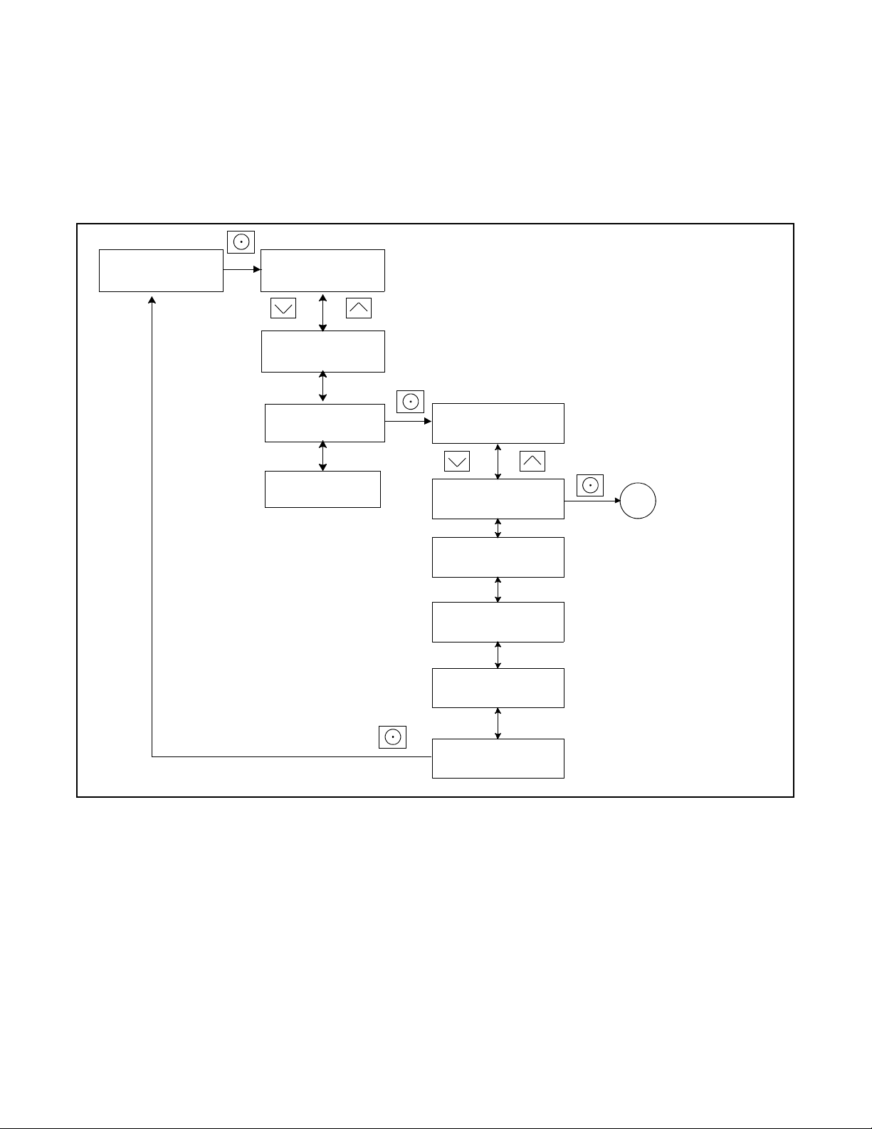
54 TP-7092 9/23
3.14 Genset System Menu
The genset system menu displays the system information shown in Figure 42. Generator sets are factory-set and should not
require changes to the system settings in the field.
A Kohler-authorized dealer can adjust these settings, if necessary. If the generator set is reconnected to a different voltage or
the system settings require adjustment for some other reason, see the Changing Settings section for instructions to enable
editing and change the system settings.
Note:
Use caution when navigating the controller menus. In some menus, pressing the Select button can enable editing of the controller
settings. Changing the settings to incorrect values can adversely affect generator set operation or render the unit inoperable.
Voltage Regulator (VR) Voltage Adj
The generator set voltage is factory set and typically does not require adjustment in the field. If voltage adjustment is required,
contact a Kohler authorized dealer for service. Refer to the generator set Installation Manual for instructions to adjust the voltage.
Fuel Type
The fuel type, LP or natural gas, is shown. Do not change the fuel type in this menu unless the generator’s fuel system has been
converted by an authorized dealer.
Setting the Exerciser
Use the Genset System menus to set the generator set exerciser. Refer to the Exercise section for instructions to set the
exerciser and for more information about exercising the generator set.
After a scheduled exercise run, the Next Exercise time and date will be updated automatically based on the Exercise Frequency
setting.
Language
Controllers can be set for the following languages: English, French, Spanish, Dutch, or German.
Adjusting the Display Contrast
To adjust the display contrast, use the down arrow button to step to the Contrast menu. Press the Select button, and then use
the up and down arrow buttons to adjust the contrast. Press the Select button to save the contrast setting.
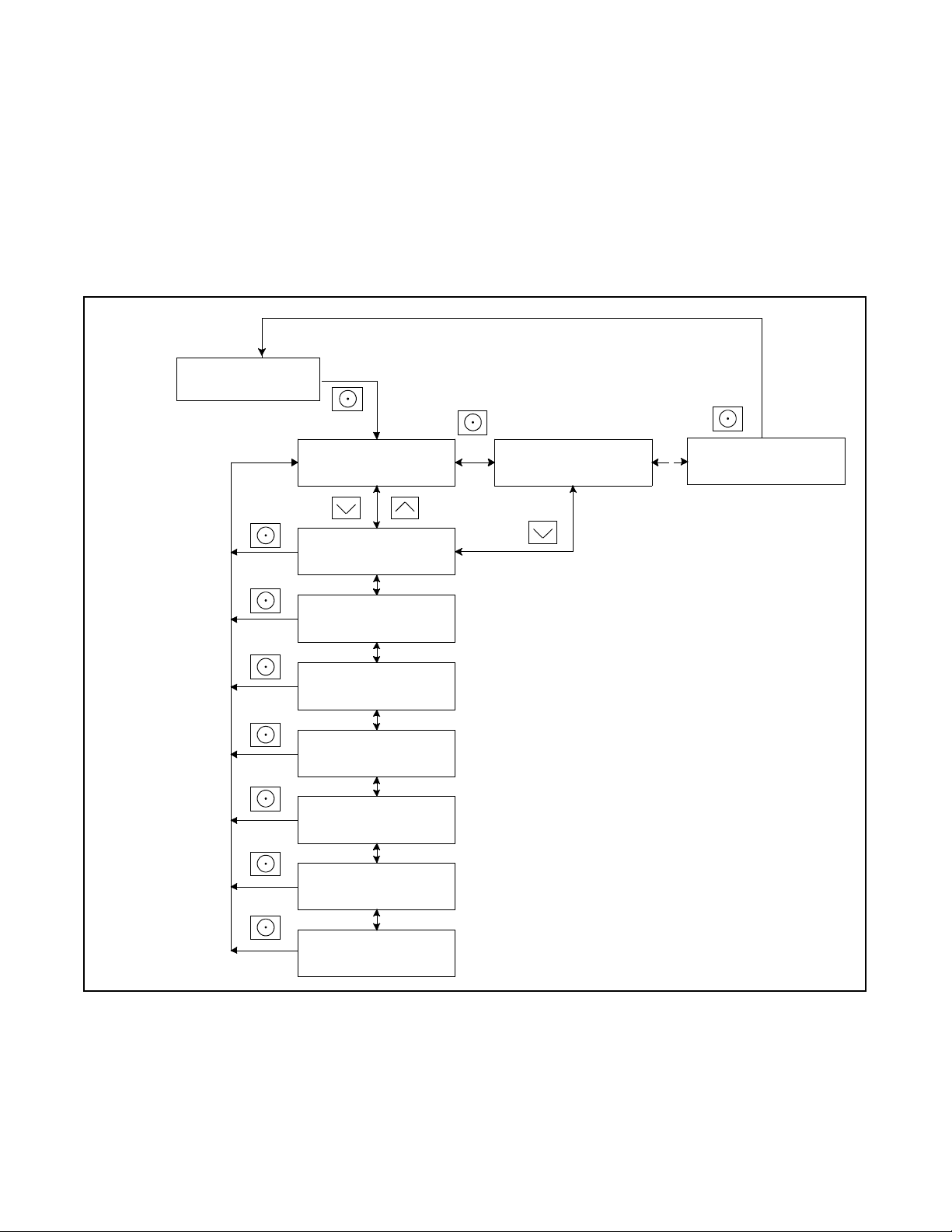
TP-7092 9/23 55
Figure 42 Genset System Menu
Genset --->
System
Note:
Actual settings may vary.
System Voltage:
240 V
System Freq:
60 Hz
VR Voltage Adj:
240.0 V
System Phase:
Single
System Battery:
12 V
Next Exercise
06:30PM 15Dec2011
Exercise Mode:
Unloaded Variable
Exercise Freq:
Weekly
Language:
English
Contrast: 50
<--- Return
Fuel Type:
LP
Tp6804
Meas System:
English
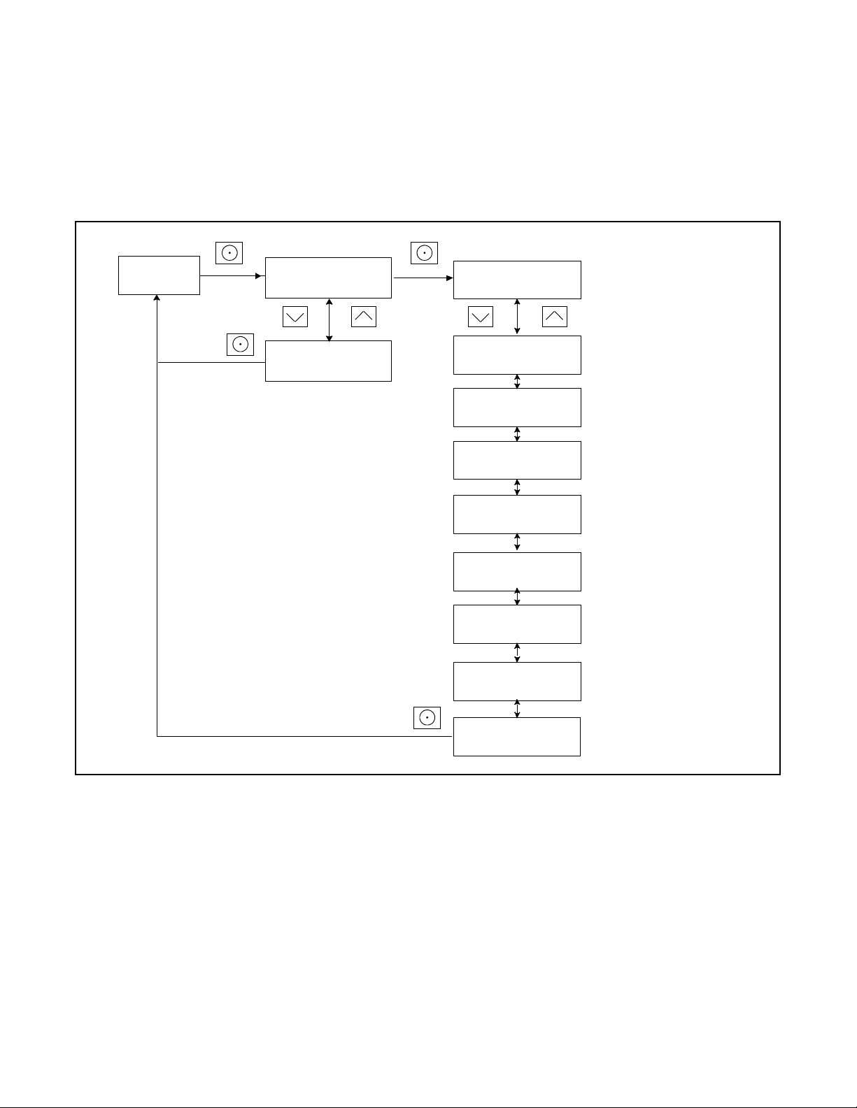
56 TP-7092 9/23
3.15 ATS Status Menu
ATS menus appear if a Model RXT transfer switch is connected to the generator set. If no transfer switch is connected, or
another model ATS is connected to the engine start connections, Remote ATS is displayed on the ATS Status screen.
The ATS Status menu displays Model RXT transfer switch and source information.
The voltage shown in these menus can be calibrated. Follow the safety precautions at the beginning of this manuals. Use a
voltmeter to measure the line-to-line voltage and follow the instructions in Figure 43 to calibrate the voltage readings.
Figure 43 ATS Status Menu, with Calibration
ATS - - >
Status
Normal Voltage:
L1- L2 240 V
Note:
If there is no Model RXT transfer switch connected to the
generator set, Remote ATS is displayed and the other
screens on this page do not appear.
Note:
Sample data shown.
tp6810
ATS Position:
Normal
Normal Status:
Not/Acceptable
Emerg. Status:
Standby
Single-phase
Three-phase
Normal Voltage:
L2- L3 240 V
Normal Voltage:
L3- L1 240 V
Normal Volts:
240.0 V
Normal Freq.:
60.0 Hz
Emerg Volts:
240.0 V
Emerg. Freq.:
60.0 Hz
Normal Freq.:
60.0 Hz
Normal Rotation:
Similar screens appear for the
emergency source.
Reset
Calibration
<- - Return
Reset
Calib? No
Reset
Calib? Yes
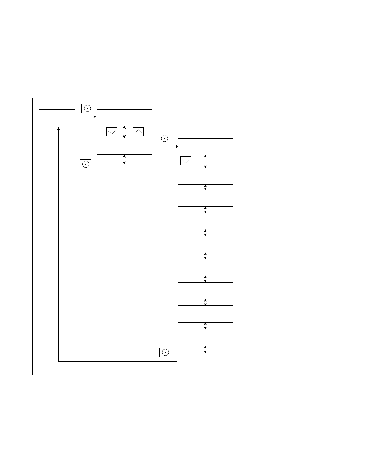
TP-7092 9/23 57
3.16 ATS Configuration Menu
Note:
The ATS Configuration menu appears only if a Model RXT transfer switch is connected.
Use the ATS Configuration submenu to check the Model RXT transfer switch system settings and time delays, and change the
settings, if necessary.
Changing ATS Configuration Settings
To enable editing, press the select button. The value flashes to indicate that it can be changed. Press the up and down arrow
buttons to change the value. Press the Select button to save the value shown.
Use the up and down arrow buttons to move to the next value to be changed. Repeat the adjustment process until all values are
correct.
Press the down arrow until Return is displayed. Press the select button to return to the main menu.
Figure 44 ATS Configuration Menu
ATS - - >
Configuration
Note:
Actual settings may vary.
tp6810
Normal Freq:
60 Hz
Normal Voltage:
240 V
Emerg. Freq:
60 Hz
Emerg. Voltage:
240 V
Emergency Start:
3 sec
Xfer frm Normal
3 sec
Xfer from Emerg:
120 sec
<- - Return
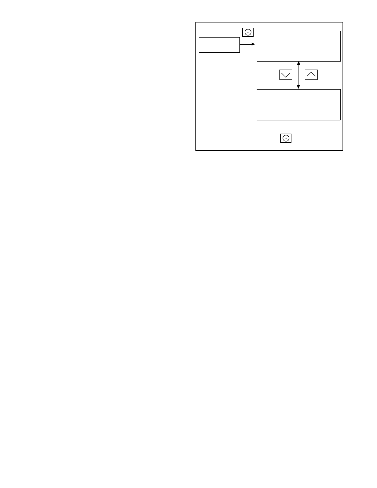
58 TP-7092 9/23
3.17 Date and Time Menu
The date and time will typically be set at controller powerup. To change the date, time, or time format (12 hour or 24 hour), use
the Date and Time menu. See Figure 45.
Figure 45 Date and Time Menu
3.18 Networking Information Menus
Use the networking menus to view and adjust communication settings for systems with remote RBUS devices such as a PIM or
load shed kit, and for systems that use the Kohler
®
OnCue
®
Plus Generator Management System.
RBUS is a proprietary RS-485 communications protocol.
The Networking Information menu leads to submenus for network and RBUS communication settings. See Figure 46.
Figure 46 Networking Information Menu
Date and Time
To change the date and time, press the Select button. See the Changing Settings section for instructions.
Date:
02Dec2011
Time:
12:34pm
Time Format:
12hr
<--- Return
Networking --->
Information
See the Network Status Submenu
section
Networking --->
Status
Networking --->
Configuration
RBUS --->
Information
<--- Return
RB
NC
NS
See the Network Configuration
Submenu
section
See the RBUS Information section
TP-6810
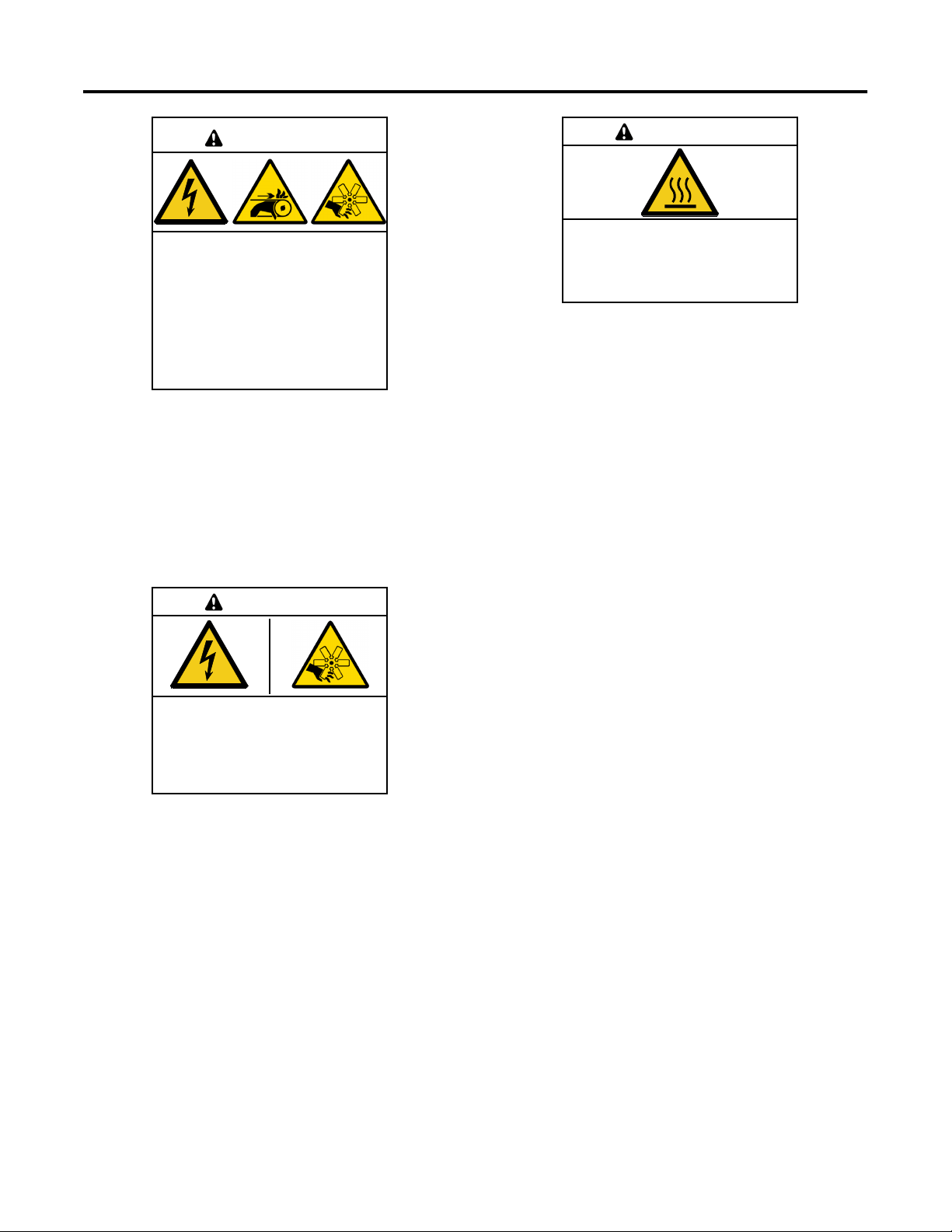
TP-7092 9/23 59
3.18.1 Networking Status Submenu
The Networking Status submenu contains settings for OnCue
®
Plus. Changes to these settings are not typically required.
If DHCP is enabled, IP parameters are not displayed. If DHCP is disabled (i.e., if a static IP address is used), the IP parameters
are displayed.
To enable or disable DHCP and change the IP settings, go to the Networking Configuration menu.
Figure 47 Network Status Submenu
Networking- -->
Information
Networking- -->
Status
OnCue Status:
Connected
IP Address:
123.456.789.123
DHCP:
Enabled
Subnet Mask:
123.456.789.123
Gateway:
123.456.789.123
DNS 1:
123.456.789.123
DNS 2:
123.456.789.123
Ethernet Status:
Disconnected
OnCue Server:
123.456.789.123
<--- Return

60 TP-7092 9/23
3.18.2 Networking Configuration Submenu (OnCue® Password)
The networking Configuration menu includes settings used for communication with the Kohler
®
OnCue
®
Plus Generator
Management System.
Password
Note:
Use the OnCue password shown on the controller display for OnCue or OnCue
®
Plus applications.
For the initial OnCue
®
Plus setup, you will be required to reset the OnCue
®
password on the RDC2 controller, and then enter it
into the OnCue
®
Plus application. To reset the password, follow the instructions in Figure 48.
Note:
The password is displayed for only 10 seconds. Be sure to write down the password and serial number.
A new password is generated each time the reset password procedure is performed. If the password is reset after the OnCue
®
Plus system has been set up, the connection will be lost. Disconnect the battery power to the controller, wait a minute, then
reconnect power.
DHCP Submenu
For most applications, the Dynamic Host Configuration Protocol (DHCP) is enabled and the IP settings cannot be changed from
the controller keypad. If DHCP is enabled, IP parameters are not displayed.
If DHCP is disabled (i.e., if a static IP address is required), then the IP parameters can be modified. For applications that require
a static IP address, press and hold the select button to enable editing, press the down arrow to disable DHCP, and then step to
the next parameters and enter the information. See Figure 48.
If an error occurs while setting a parameter, an error message is displayed and then the controller exits the edit mode. Previous
settings are preserved.

TP-7092 9/23 61
Figure 48 Networking Configuration Submenu
Networking--->
Information
Press Select to enter YES or
NO as displayed. New
password is displayed for
approximately 10 seconds.
UP arrow for YES,
Down arrow for NO.
Networking--->
Status
Networking
Configuration
Reset OnCue
Password
DHCP:
Enabled
<--- Return
Reset OnCue
Password? No
Reset OnCue
Password? Yes
S/N: 1234567
New PW: 12345
HOLD
tp6804
HOLD
RBUS - - >
Information
DHCP:
Disabled
IP Address:
123.456.789.123
Subnet Mask:
123.456.789.123
Gateway:
123.456.789.123
DNS 1:
123.456.789.123
DNS 2:
123.456.789.123
UP arrow to enable,
Down arrow to disable.
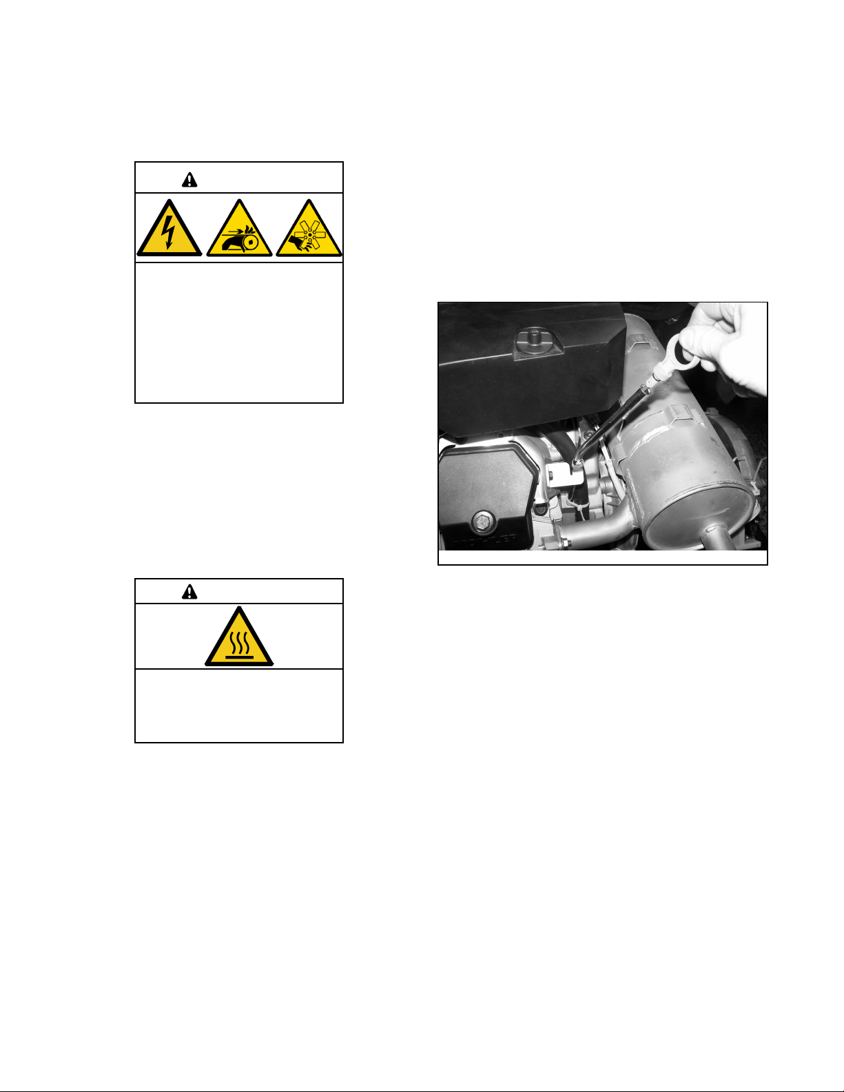
62 TP-7092 9/23
3.18.3 RBUS Information
The RBUS Information menu contains settings for remote modules that communicate with the RDC2 controller using RBUS
protocol. This includes the following optional modules:
• Model RXT transfer switch
• Combined interface/ load management board on the RXT transfer switch
• Programmable Interface Module (PIM)
• Load shed kit
• PowerSync
®
Automatic Paralleling Module (APM)
Figure 49 RBUS Information Submenu
Networking--->
Information
Networking--->
Status
Networking--->
Configuration
RBUS--->
Information
<---- Return
Modules
Connected: 2
Remote --->
Devices
Net Cycle Time:
123ms
Module Timeouts:
1234
Module Errors:
1234
<---- Return
RD
See the Remote Devices Submenu
section
tp6804
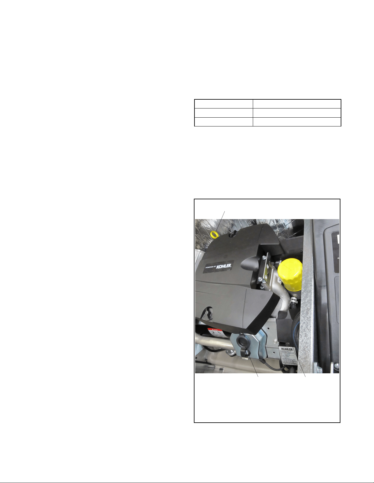
TP-7092 9/23 63
3.18.4 Remote Devices Submenu
Check the status of remote devices communicating through RBUS. Device types can include:
• Model RXT ATS
• Programmable Interface Module (PIM)
• Load shed kit or combined interface/ load management board on a Model RXT transfer switch
• PowerSync
®
Automatic Paralleling Module (APM)
The serial number for the RBUS module is shown on the circuit board inside the module enclosure.
Figure 50 Remote Devices Submenu
From the RBUS Information
section
Remote --->
Devices
Connected: Displays the date and time that the device was connected.
Disconnected: Displays the last date and time of successful
communication.
S/N: XXXXXXXXX
<<*DeviceType*>>
S/N: XXXXXXXXX
<<*DeviceType*>>
<---- Return
Module Status:
Connected
Comm. Errors:
12345
Comm. Timeouts:
12345
Module ID:
12
Firmware Ver.:
4.07
(Dis)Connected:
MM/DD/YY 12:12 PM
Return --->
tp6804
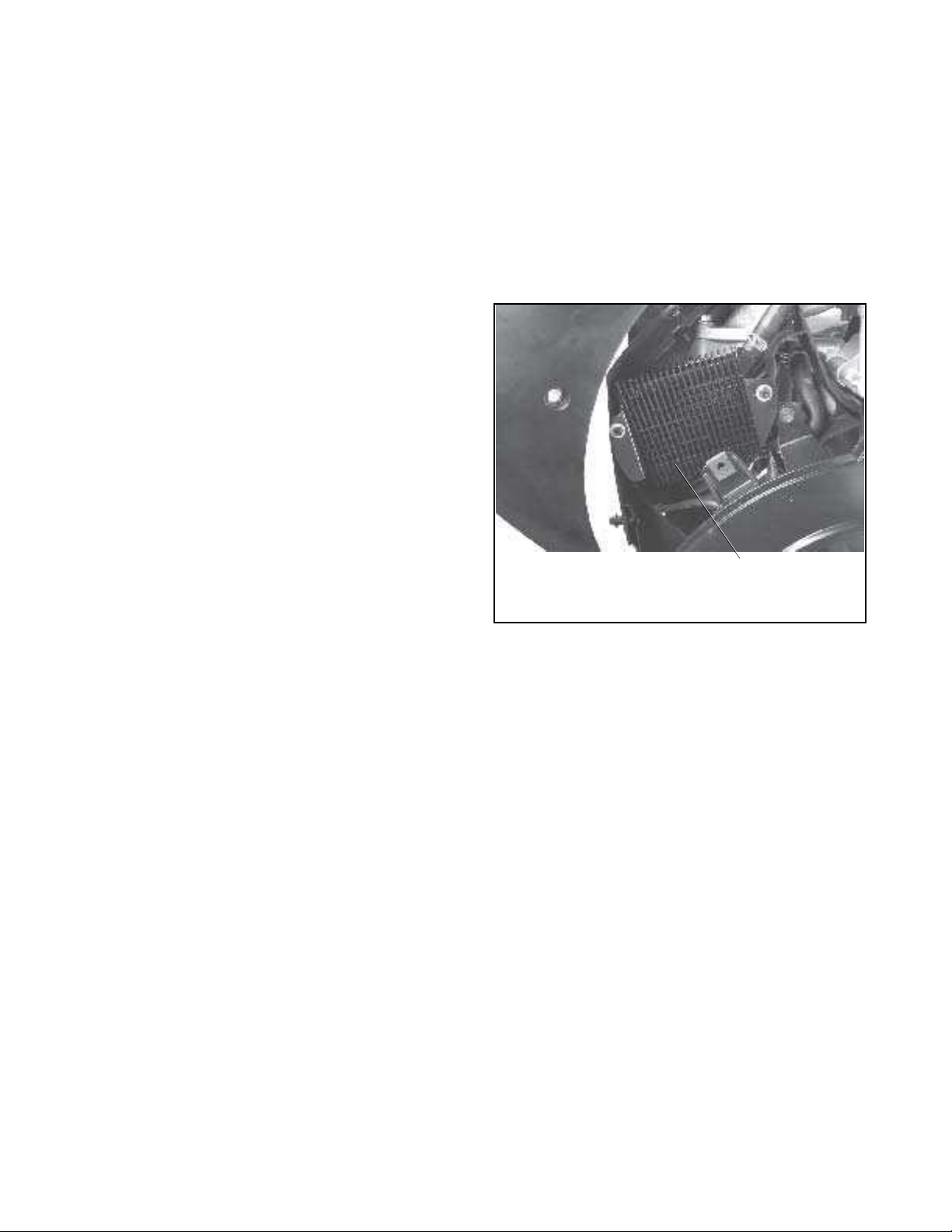
64 TP-7092 9/23
3.19 Programmable Interface Module (PIM) Status Menu
The PIM status menu displays the status of inputs and outputs connected to the programmable interface module (PIM). This
menu appears only if a PIM is connected. This is a status display menu only. Input and output settings cannot be changed from
the RDC2 controller’s user interface.
A personal computer running Kohler
®
SiteTech™ software is required to change the input and output settings. Contact an
authorized dealer for service.
The Kohler
®
OnCue
®
Plus Management System can be used to turn outputs on and off. See the OnCue
®
Plus Software
Operation Manual for instructions.
Figure 51 Programmable Interface Module (PIM) Status Menu
PIM
Status:
<--- Return
PIM 1 --->
Input 1
In/Active
Input 2
In/Active
Output 1:
In/Active
Output 2:
In/Active
Output 3:
In/Active
Output 4:
In/Active
Output 5:
In/Active
Output 6:
In/Active
<--- Return
tp6810

TP-7092 9/23 65
3.20 Load Control Menus
The Load Control menu displays the status of the load management device inputs and outputs, and allows a test of the load
control output relays. This menu appears only if a load management device (load shed kit or Model RXT transfer switch with the
combined interface/ load management board) is connected.
Generator current is displayed as a percent of the maximum generator capacity. The load control module adds and sheds loads
based on the generator current.
The test function cycles the relays in the order of their priority. For detailed information, refer to the instructions provided with
the load shed kit. For the RXT combined interface/ load management board, refer to the RXT automatic transfer switch Operation
and Installation Manual.
Figure 52 Load Control Status Menu
Load - - >
Control
Generator
Current: 123 %
tp6810
Load - - >
Control 1
<- - Return
Test Outputs
Push Select (blinking)
Input 1:
In/Active
Input 2:
In/Active
Output 1:
Add/Shed
Output 2:
Add/Shed
Output 3:
Add/Shed
Output 4:
Add/Shed
Output 5:
Add/Shed
Output 6:
Add/Shed
<- - Return
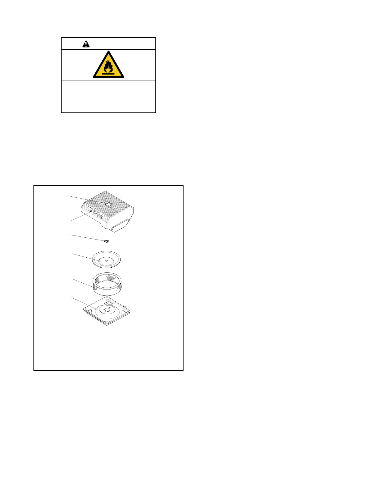
66 TP-7092 9/23
3.21 Event Log
The event log displays up to 1000 controller faults and notices, starting with the most recent event. Events are numbered
1-1000, with 1 being the most recent. Each event is displayed with the date and time of the event, the number of the event, a
code to indicate whether the event was a warning (W), shutdown (S), or informational notice (I), the engine hours at the time of
the event, and the event description.
The time and date for notices (I) are not stored in the controller.
Procedure to View Event History
1. Press Select to enter the main menu.
2. Press the down arrow to step down to the event log.
3. Press Select to display the most recent event.
4. Press the down arrow to step to the next event.
5. Use the up and down arrow buttons to view events.
6. Press the Select button to exit the event log.
To stop viewing the event history before the last event, press the select button to return to the main menu.
Figure 53 Event Log
Event Log --->
Press Select button at any time to return to the main menu.
Press UP and Down arrow buttons to scroll through events
Date MO/DA/YEAR
time HR:MN
event number, W/S/I, engine hours
event name
Date MO/DA/YEAR
time HR:MN
event number, W/S/I, engine hours
event name
tp6810
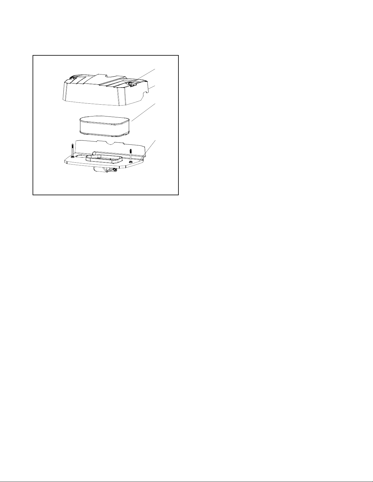
TP-7092 9/23 67
Section 4. Scheduled Maintenance
WARNING
Accidental starting.
Can cause severe injury or death.
Disconnect the battery cables before working on the generator set. Remove the
negative (–) lead first when disconnecting the battery. Reconnect the negative (–)
lead last when reconnecting the battery.
Disabling the generator set. Accidental starting can cause severe injury or death. Before working on the generator set or
equipment connected to the set, disable the generator set as follows: (1) Press the generator set off/reset button to shut down
the generator set. (2) Disconnect the power to the battery charger, if equipped. (3) Remove the battery cables, negative (–) lead
first. Reconnect the negative (–) lead last when reconnecting the battery. Follow these precautions to prevent the starting of the
generator set by the remote start/stop switch.
DANGER
Hazardous voltage. Moving parts.
Will cause severe injury or death.
Operate the generator set only when all guards and electrical enclosures are in place.
WARNING
Hot engine and exhaust system.
Can cause severe injury or death.
Do not work on the generator set until it cools.
Servicing the exhaust system. Hot parts can cause severe injury or death. Do not touch hot engine parts. The engine and
exhaust system components become extremely hot during operation.
4.1 Scheduled Maintenance
Refer to the following service schedules and the runtime hours displayed on the controller display to schedule routine
maintenance. Intervals are shown in hours of operation and/or time intervals (i.e. weekly, monthly, quarterly, etc.) Have an
authorized dealer service the generator set at the designated intervals in the service schedule for the life of the generator set.
Service units subject to extreme weather, long operating hours, or dusty or dirty conditions more frequently.
Contact an authorized dealer for parts.
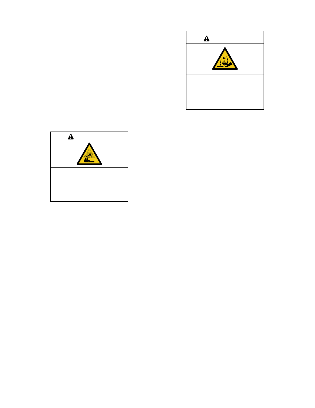
68 TP-7092 9/23
4.1.1 Service Schedule, 14 kW Models
System Component or Procedure
Procedure
Frequency
Visually
Inspect
Check
Change
Clean
Test
Fuel
Flexible lines and connections
X
R
Quarterly
Main tank supply level
X
Weekly
Fuel piping
X
Yearly
Lubrication
Oil level
X
X
Every 8 hours. of
engine operation
Crankcase breather hose
X
Yearly or 500 hours
Change oil
X
Yearly or 100 hours
Replace filter
X
Yearly or 200 hours
Cooling
Air ducts, louvers
X
X
Yearly
Exhaust Line
Leakage
X
X
Weekly
Insulation, fire hazards
X
Yearly
Obstructions or combustible materials near exhaust
outlet
X
Weekly
DC Electrical System
Check battery charger operation, charge rate
X
Monthly
Remove corrosion, clean and dry battery and rack
X
X
Yearly
Clean and tighten battery terminals and inspect
boots
X
X
Yearly
Battery electrolyte level and specific gravity *
X
Yearly
AC Electrical System
Tighten control and power wiring connections
X
Yearly
Remote control system, if equipped
X
Monthly
Visible wear or damage
X
Quarterly
Wire abrasions where subject to motion
X
X
6 months
Wire-cable insulation condition
X
3 years or 500 hours
Engine and Mounting
Visible wear or damage
X
Weekly
Air cleaner service †
150
300
Yearly or hours shown
Spark plugs
300
Replace stepper motor coupling and bushing
D
500 hours
Generator
Visible wear or damage
X
Quarterly
Exercise generator set
X
Weekly
Brushes and collector ring
D
D
Yearly or 300 hours
Measure and record resistance readings of
windings with insulation tester (Megger
®
, with SCR
assembly or rectifier and load leads disconnected)*
D
3 years
General Condition of Equipment
Evidence of vibration, leakage, unusual or
excessive noise, temperature, or deterioration
X
X
X
Weekly
Interior of sound enclosure
X
X
Quarterly
Not necessary for maintenance-free batteries.
X Action
† Service more frequently under extremely dusty/dirty conditions.
D Authorized dealer only
Megger
®
is a registered trademark of Biddle Instruments.
R Replace as necessary
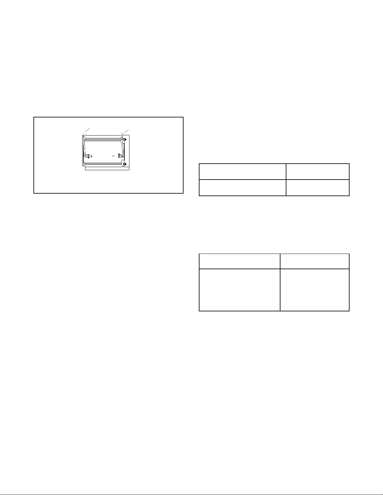
TP-7092 9/23 69
4.1.2 Service Schedule, 20 and 26 kW Models
System Component or Procedure
Procedure
Frequency
Visually
Inspect
Check
Change
Clean
Test
Fuel
Flexible lines and connections
X
R
Quarterly
Main tank supply level
X
Weekly
Fuel piping
X
Yearly
Lubrication
Oil level, 20 kW models
X
8 hours of operation
Oil Level, 26 kW models
X
24 hours of operation
Crankcase breather hose
X
Yearly or 500 hours
Standard oil change, 20 and 26 kW models
X
Yearly or 150 hours
Premium oil change, 26 kW models
X
2 years or 300 hours
Replace filter
X
With each oil change
Oil Cooler
X
X
Yearly or 150 hours
Cooling
Air ducts, louvers
X
X
Yearly
Exhaust System
Leakage
X
X
Weekly
Insulation, fire hazards
X
Yearly
Obstructions or combustible materials near exhaust
outlet
X
Weekly
DC Electrical System
Check battery charger operation, charge rate
X
Monthly
Remove corrosion, clean and dry battery and rack
X
X
Yearly
Clean and tighten battery terminals and inspect
boots
X
X
Yearly
Battery electrolyte level and specific gravity *
X
Yearly
AC Electrical System
Tighten control and power wiring connections
X
Yearly
Remote control system, if equipped
X
Monthly
Visible wear or damage
X
Quarterly
Wire abrasions where subject to motion
X
X
6 months
Wire-cable insulation condition
X
3 years or 500 hours
Engine and Mounting
Visible wear or damage
X
Weekly
Air cleaner service †
150
300
Yearly or hours shown
Spark plugs
150
300
Replace stepper motor coupling and bushing
D
500 hours
Generator
Visible wear or damage
X
Quarterly
Exercise generator set
X
Weekly
Brushes and collector ring
D
D
Yearly or 300 hours
Measure and record resistance readings of
windings with insulation tester (Megger
®
, with SCR
assembly or rectifier and load leads disconnected)*
D
3 years
General Condition of Equipment
Evidence of vibration, leakage, unusual or
excessive noise, temperature, or deterioration
X
X
X
Weekly
Interior of sound enclosure
X
X
Quarterly
Not necessary for maintenance-free batteries.
X Action
† Service more frequently under extremely dusty/dirty conditions.
D Authorized dealer only
Megger
®
is a registered trademark of Biddle Instruments.
R Replace as necessary
70 TP-7092 9/23
4.2 Lubrication System
See the service schedules section for oil change and oil filter replacement intervals. See the service views section for the oil
drain, oil dipstick, oil fill, and oil filter locations.
WARNING
Accidental starting.
Can cause severe injury or death.
Disconnect the battery cables before working on the generator set. Remove the
negative (–) lead first when disconnecting the battery. Reconnect the negative (–)
lead last when reconnecting the battery.
Disabling the generator set. Accidental starting can cause severe injury or death. Before working on the generator set or
equipment connected to the set, disable the generator set as follows: (1) Press the generator set off/reset button to shut down
the generator set. (2) Disconnect the power to the battery charger, if equipped. (3) Remove the battery cables, negative (–) lead
first. Reconnect the negative (–) lead last when reconnecting the battery. Follow these precautions to prevent the starting of the
generator set by the remote start/stop switch.
WARNING
Hot engine and exhaust system.
Can cause severe injury or death.
Do not work on the generator set until it cools.
4.2.1 Low Oil Pressure Shutdown
The low oil pressure (LOP) shutdown feature protects the engine against internal damage if the oil pressure drops below a
minimum pressure because of oil pump failure or other malfunction. See the Faults section for instructions if the generator set
shuts down on a fault.
Note:
The LOP shutdown feature does not protect against damage caused by operating when the oil level is low; it is not a low oil level
shutdown. Check the oil level regularly, and add oil as needed.
4.2.2 Low Oil Level Switch (26RCA)
The low oil level switch protects the engine against internal damage if the oil pressure drops below a minimum level. The engine
shuts down and a fault message is displayed on the controller if the oil level is too low. See the Faults section for instructions if
the generator set shuts down on a fault.
Check the oil level regularly and add oil as needed.
4.2.3 Oil Check
The generator set is shipped with oil. Before operating the generator set, check the engine oil in the crankcase.
To check the oil level, shut down the generator set and wait several minutes. Remove the dipstick and wipe the end clean,
reinsert, and remove. See Figure 54. Maintain the oil level between the Add and Full marks on the dipstick. Add oil when the
level is low.
Note:
See the next section for oil specifications. Do not mix oil types when adding oil.
Check the oil level before each use. For extended operation, check the oil level periodically as shown in the maintenance
schedule for your model. Do not check the oil level when the generator set is running. Shut down the generator set and wait
several minutes before checking the oil.

TP-7092 9/23 71
Figure 54 Dipstick and Oil Fill Locations
4.2.4 Engine Oil Recommendation
Use 5W-30 or 10W-30 API (American Petroleum Institute) Service Class SG, SH, or SJ synthetic oil. Synthetic oil oxidizes and
thickens less than other oils and leaves the engine intake valves and pistons cleaner.
For the 26 kW model, 10W-50 extended-life synthetic oil is also available. This premium oil requires fewer oil changes. See the
Service Schedule for oil change intervals.
4.2.5 Oil Change Procedure
Note:
Dispose of all waste materials (engine oil, fuel, filter, etc.) in an environmentally safe manner.
Drain the oil while it is still warm.
1. Drain the oil.
a. Press the OFF button on the generator set controller.
b. Disconnect the utility power to the generator set.
c. Disconnect the generator set engine starting battery, negative (–) lead first.
d. Remove the end panels from the enclosure by lifting the panels up and out. Then lift off the service-side panel
to access the oil drain valve and hose.
e. Clean the area around the dipstick and oil fill cap.
f. Remove the oil drain hose from its retaining clip. Remove the cap from the oil drain hose and lower the hose
into an oil collection container.
g. Open the oil drain valve on the engine.
h. Remove the dipstick and oil fill cap. Allow time for the engine oil to drain completely.
i. Close the oil drain valve. Replace the cap on the oil drain hose. Replace the oil drain hose in its retaining clip.
j. Replace the dipstick.
2. Replace the oil filter.
a. Clean the area around the oil filter.
b. Loosen the oil filter by rotating it counterclockwise with an oil filter wrench. On 20 and 26 kW models, allow
the oil to drain from the filter. Then remove the oil filter.
c. Clean the gasket sealing surface of the oil filter adapter.
d. Apply a light coat of clean oil to the rubber seal of the new oil filter.
e. Install the new oil filter following the instructions provided with the filter.
7092
1. Dipstick
2. Oil Fill
1
1
1
2
2
2
14 kW
20 kW
26 kW

72 TP-7092 9/23
3. Fill with oil.
Note:
When the oil is drained, some oil remains in the engine. The amount of oil needed to refill the engine may be less than
the capacity shown in Figure 55. Use the dipstick to check the oil level during the fill. Do not fill past the full mark on the
dipstick.
Note:
See the Engine Oil Recommendation section for the recommended oil type.
Generator Set Model
Oil Capacity, L (qt.)
14 kW
1.8 (1.9)
20/26 kW
1.9 (2.0)
Figure 55 Engine Oil Capacity
a. Add oil through the oil fill port; see the Oil Check section for the oil fill port location.
b. Use the dipstick to check the oil level before starting to add the final quart of oil. Fill the engine to the F mark
on the dipstick.
c. Reinstall the dipstick and the oil fill cap.
d. Reconnect the generator set engine starting battery, negative (–) lead last.
e. Reconnect the utility power to the generator set.
f. Press the RUN button on the generator set controller. The generator set will start.
g. Run the generator set for a minute to allow the oil pressure to reach operating range.
h. Stop the generator set, wait 1 minute, and then recheck the oil level. Add oil to bring the level up to the F mark
on the dipstick.
4. Check for leaks.
a. Check for oil leaks.
b. Fix leaks and recheck the oil level.
c. Reinstall the housing side panel.
5. Reset the maintenance timer on the controller.
4.2.6 Resetting the Maintenance Timer
1. From the Overview menu, step down to the Genset Run Time menu.
2. Press the Select button and then step down to the Next Maintenance screen.
3. Press the Select button.
4. Press the Up arrow button so that “Reset Maint Timer? Yes” is displayed.
5. Press the Select button. After about two minutes, the new maintenance interval and date are displayed.
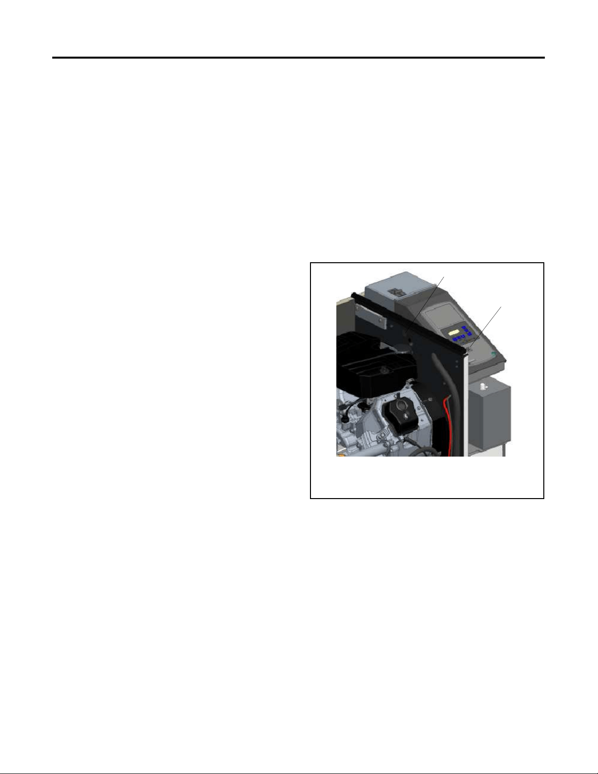
TP-7092 9/23 73
4.2.7 Oil Cooler (20RCA/L and 26RCA/L only)
Inspect and clean the oil cooler at the intervals indicated in the service schedule. The oil cooler must be kept free of debris.
See Figure 56 for the oil cooler location. The oil cooler is located under the No. 2 cylinder shroud. Remove the top mounting
screw and loosen the two side screws, then lift off the cylinder shroud.
Clean the outside of the oil cooler fins with a brush or with compressed air.
Figure 56 Oil Cooler
4.3 Spark Plugs
WARNING
Accidental starting.
Can cause severe injury or death.
Disconnect the battery cables before working on the generator set. Remove the
negative (–) lead first when disconnecting the battery. Reconnect the negative (–)
lead last when reconnecting the battery.
Disabling the generator set. Accidental starting can cause severe injury or death. Before working on the generator set or
equipment connected to the set, disable the generator set as follows: (1) Press the generator set off/reset button to shut down
the generator set. (2) Disconnect the power to the battery charger, if equipped. (3) Remove the battery cables, negative (–) lead
first. Reconnect the negative (–) lead last when reconnecting the battery. Follow these precautions to prevent the starting of the
generator set by the remote start/stop switch.
WARNING
Hot engine and exhaust system.
Can cause severe injury or death.
Do not work on the generator set until it cools.
Oil cooler
62 590 01
Note:
See the
Oil Fill Components section for location.
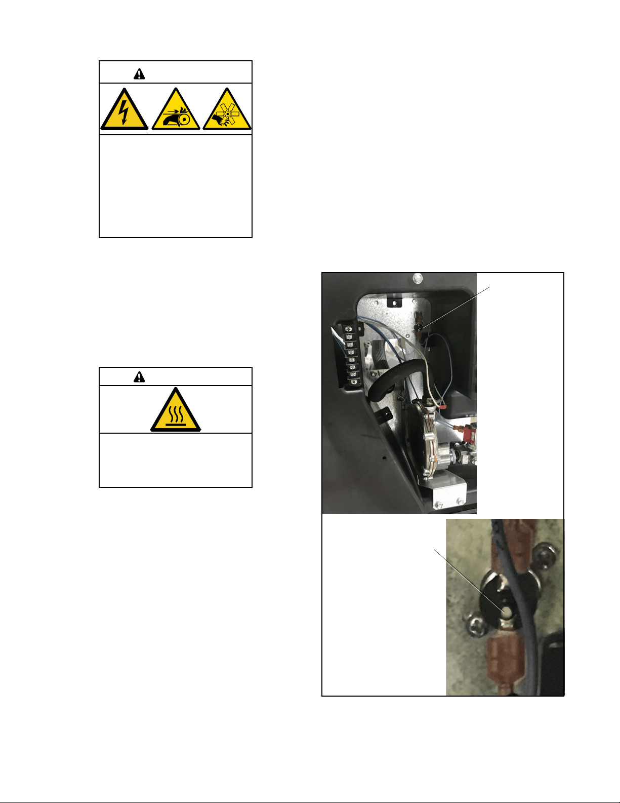
74 TP-7092 9/23
Reset the spark plug gap or replace the plugs with new plugs as necessary.
1. Clean the area around the base of the spark plug to keep dirt and debris out of the engine.
2. Remove the spark plug and check its condition. Replace the spark plug if it is worn or if its reuse is questionable.
3. Check the spark plug gap using a wire feeler gauge. See Figure 57 for the recommended spark plug gap. Adjust the
gap by carefully bending the ground electrode. See Figure 58 and Figure 59.
4. Reinstall the spark plug into the cylinder head. Torque the spark plug to 24.4-29.8 Nm (18-22 ft. lb.)
Generator Set Model
Spark Plug Gap
14/20/26 kW models
0.76 mm (0.030 in.)
Figure 57 Spark Plug Gap
Figure 58 Checking the Spark Plug Gap
Figure 59 Adjusting the Spark Plug Gap
1-514
1-511

TP-7092 9/23 75
4.4 Air Cleaner Service
WARNING
Risk of fire.
Can cause severe injury or death.
Do not smoke or permit flames or sparks near fuels or the fuel system.
Servicing the air cleaner. A sudden backfire can cause severe injury or death. Do not operate the generator set with the
air cleaner removed.
4.4.1 Air Cleaner, 14 kW Models
The engine has a replaceable high-density paper air cleaner element. See Figure 60.
Figure 60 Air Cleaner Components
Check for a buildup of dirt and debris around the air cleaner system. Keep this area clean. Also check for loose or damaged
components. Replace all bent or damaged air cleaner components.
Note:
Operating the engine with loose or damaged air cleaner components could allow unfiltered air into the engine causing premature
wear and failure.
Air Cleaner Service
Use the following procedure to replace the paper element at the intervals specified in the service schedule. Replace the paper
element more often under extremely dusty or dirty conditions.
1. Press the OFF button on the generator set controller.
2. Disconnect the utility power to the generator set.
3. Disconnect the generator set engine starting battery, negative (–) lead first.
4. Loosen the cover retaining knob and remove the cover.
5. Remove the element cover nut, element cover, and the paper element.
Note:
Do not wash the paper element or clean it with pressurized air, as this will damage the element.
6. Replace the element if it is dirty, bent, or damaged.
Cover knob
Air cleaner cover
Element cover nut
Element cover
Air cleaner element
Air cleaner base
586536

76 TP-7092 9/23
7. Check the air cleaner base. Make sure it is secure and not bent or damaged. Also check the element cover for damage
and fit. Replace all damaged air cleaner components. Remove any loose dirt or debris from the air cleaner base. Wipe
the base carefully so that no dirt drops into the intake throat. Check the condition of the rubber seal on the air cleaner
stud and replace the seal if necessary.
8. Reinstall the paper element, element cover, element cover nut, and the air cleaner cover. Secure the cover with the
cover retaining knob.
9. Reconnect the utility power to the generator set.
10. Reconnect the generator set engine starting battery, negative (–) lead last.
4.4.2 Air Cleaner, 20/26 kW Models
The engine is equipped with a replaceable, high density paper air cleaner element. See Figure 61.
Figure 61 Air Cleaner Components
Check the air cleaner daily or before starting the engine. Check for a buildup of dirt and debris around the air cleaner system.
Keep this area clean. Also check for loose or damaged components. Replace all bent or damaged air cleaner components.
Note:
Operating the engine with loose or damaged air cleaner components could allow unfiltered air into the engine causing premature
wear and failure.
Air Cleaner Service
Use the following procedure to replace the paper element at the intervals specified in the service schedule. See Service
Schedule, 20 and 26 kW Models. See Figure 61 for the air cleaner components.
1. Loosen the two cover retaining knobs and remove the cover.
2. Remove the paper element.
3. Do not wash the paper element or use pressurized air, as this will damage the element. Replace a dirty, bent, or
damaged element. Handle new elements carefully; do not use if the sealing surfaces are bent or damaged.
4. When servicing the air cleaner, check the air cleaner base. Make sure it is secured and not bent or damaged. Also,
check the element cover for damage or improper fit. Replace all damaged air cleaner components.
Note:
If any loose dirt or debris fell on the air cleaner base when the element was removed, carefully remove it, and wipe the
base clean. Be careful that none of it drops into the intake throat.
5. Reinstall the paper element onto the air cleaner base. Make sure the element is flat and properly seated.
6. Install the air cleaner cover and secure with the two retaining knobs.
7. When element replacement is necessary, order genuine Kohler parts.
Knobs (qty. 2)
Cover
Paper element
Base
tp6515

TP-7092 9/23 77
4.5 Cooling System
The engine fan draws cooling air through the openings in the sides and end near the battery. The alternator fan draws cooling
air through openings on the side walls of the enclosure. The cooling air mixes with the engine exhaust and is discharged at the
exhaust outlet. See the service view section for air intake and exhaust locations. To prevent generator set damage caused by
overheating, keep the housing cooling inlets and outlets clean and unobstructed at all times.
Note:
Do not block the generator set cooling air inlets or mount other equipment above them. Overheating and severe generator
damage may occur.
4.6 Exhaust System
WARNING
Carbon monoxide.
Can cause severe nausea, fainting, or death.
The exhaust system must be leakproof and routinely inspected.
Remove all combustible materials from the exhaust location. Combustible materials include building materials as well as natural
surroundings. Keep dry field grass, foliage, and combustible landscaping material a minimum of 1.2 m (4 ft.) from the exhaust
outlet.
Periodically inspect the exhaust system components for cracks, leaks, and corrosion.
• Check for corroded or broken metal parts and replace them as needed.
• Check that the exhaust outlet is clear.
4.7 Battery
WARNING
Sulfuric acid in batteries.
Can cause severe injury or death.
Wear protective goggles and clothing. Battery acid may cause blindness and burn skin.
Battery electrolyte is a diluted sulfuric acid. Battery acid can cause severe injury or death. Battery acid can cause
blindness and burn skin. Always wear splashproof safety goggles, rubber gloves, and boots when servicing the battery. Do not
open a sealed battery or mutilate the battery case. If battery acid splashes in the eyes or on the skin, immediately flush the
affected area for 15 minutes with large quantities of clean water. Seek immediate medical aid in the case of eye contact. Never
add acid to a battery after placing the battery in service, as this may result in hazardous spattering of battery acid.
Battery acid cleanup. Battery acid can cause severe injury or death. Battery acid is electrically conductive and corrosive.
Add 500 g (1 lb.) of bicarbonate of soda (baking soda) to a container with 4 L (1 gal.) of water and mix the neutralizing solution.
Pour the neutralizing solution on the spilled battery acid and continue to add the neutralizing solution to the spilled battery acid
until all evidence of a chemical reaction (foaming) has ceased. Flush the resulting liquid with water and dry the area.
Battery gases. Explosion can cause severe injury or death. Battery gases can cause an explosion. Do not smoke or permit
flames or sparks to occur near a battery at any time, particularly when it is charging. Do not dispose of a battery in a fire. To
prevent burns and sparks that could cause an explosion, avoid touching the battery terminals with tools or other metal objects.
Remove all jewelry before servicing the equipment. Discharge static electricity from your body before touching batteries by first
touching a grounded metal surface away from the battery. To avoid sparks, do not disturb the battery charger connections while
the battery is charging. Always turn the battery charger off before disconnecting the battery connections. Ventilate the
compartments containing batteries to prevent accumulation of explosive gases.

78 TP-7092 9/23
Battery short circuits. Explosion can cause severe injury or death. Short circuits can cause bodily injury and/or equipment
damage. Disconnect the battery before generator set installation or maintenance. Remove all jewelry before servicing the
equipment. Use tools with insulated handles. Remove the negative (–) lead first when disconnecting the battery. Reconnect the
negative (–) lead last when reconnecting the battery. Never connect the negative (–) battery cable to the positive (+) connection
terminal of the starter solenoid. Do not test the battery condition by shorting the terminals together.
Refer to this section for general battery information and maintenance. Also consult the battery manufacturer’s instructions for
battery maintenance.
All generator set models use a negative ground with a 12-volt engine electrical system. Consult the generator set nameplate for
the engine electrical system voltage. Consult the generator spec sheet for battery size and capacity recommendations for
replacement purposes. Wiring diagrams provide battery connection information. See Figure 62 for typical battery connections.
Figure 62 12-Volt Engine Electrical System Single Starter Motor, Typical Battery Connection
4.7.1 Cleaning the battery
Clean the battery and cables and tighten battery terminals using the service schedule recommendations. To prevent corrosion,
maintain tight, dry electrical connections at the battery terminals. To remove corrosion from battery terminals, disconnect the
cables from the battery and scrub the terminals with a wire brush. Clean the battery and cables with a solution of baking soda
and water. After cleaning, flush the battery and cables with clean water and wipe them with a dry, lint-free cloth.
After reconnecting the battery cables, coat the battery terminals with petroleum jelly, silicone grease, or other nonconductive
grease.
4.7.2 Checking Electrolyte Level
Check the electrolyte level of batteries with filler caps monthly. Remove filler caps and verify that electrolyte level reaches bottom
of filler holes. Refill as necessary with distilled water. DO NOT add fresh electrolyte. Tighten all filler caps. If water is added
during freezing temperatures, run the generator set for 20- 30 minutes to mix the electrolyte and water to prevent battery damage
from freezing.
To ground (–) terminal on or near starter motor
To positive (+) terminal on starter solenoid
EZ-273000-J

TP-7092 9/23 79
4.7.3 Checking Specific Gravity
Use a battery hydrometer to check the specific gravity of the electrolyte in each battery cell. While holding the hydrometer
vertically, read the number on the glass bulb at the top of the electrolyte level or the number adjacent to the pointer. If the
hydrometer used does not have a correction table, use the correction factors in Figure 65. Determine specific gravity and
electrolyte temperature of battery cells. Locate temperature in Figure 65 and adjust the specific gravity by the amount shown.
The battery is fully charged if the specific gravity is 1.260 at an electrolyte temperature of 80°F (26.7°C). The difference between
specific gravities of each cell should not exceed ±0.01. Charge the battery if the specific gravity is below 1.215 at an electrolyte
temperature of 80°F (26.7°C). See Figure 63.
Specific Gravity,
Corrected to 80°F (26.7°C)
Battery Condition
Below 1.215
Needs charging
1.260
Fully charged
Figure 63 Specific Gravity Interpretation
Some battery testers have four or five beads in a test tube. Draw electrolyte into the tube as performed with the battery
hydrometer described previously. Use the manufacturer’s instructions. Use Figure 64 to interpret typical test results.
Number of Floating Beads
Battery Condition
5
Overcharged
4
Fully Charged
3
A good charge
1 or 2
A low charge
0
A dead charge
Figure 64 Bead-Type Test Interpretation
Figure 65 Specific Gravity Temperature Correction
Correction
Example No. 1
Temperature below 26.7°C (80°F)
Hydrometer Reading 1.250
Acid Temperature - 6.7°C (20°F)
Subtract .024 Specific Gravity
Corrected Specific Gravity is 1.226
1.250 - .024 = 1.226
Example No. 2
Temperature above 26.7°C (80°F)
Hydrometer Reading 1.235
Acid Temperature 37.8°C (100°F)
Add .008 Specific Gravity
Corrected Specific Gravity is 1.243
1.235 + .008 = 1.243
The temperature correction amounts to about .004 (4 points) of
specific gravity for each 5.5°C (10°F) change in temperature.
1-787

80 TP-7092 9/23
4.8 Storage Procedure
Perform the following storage procedure before removing the generator set from service for three months or longer. Follow the
engine manufacturer’s recommendations for storage, if available.
Note:
Run the generator set monthly whenever possible.
4.8.1 Lubricating System
1. Operate the generator set until it reaches operating temperature, or about 15 minutes.
2. Stop the generator set.
3. While the engine is still warm, drain the engine lubrication oil from the engine crankcase.
4. Refill engine crankcase with oil. See the Engine Oil Recommendation section for oil recommendations.
5. Run the generator set for a few minutes to distribute the clean oil.
6. Stop the generator set.
4.8.2 Fuel System
1. Start the generator set.
2. With the generator set running, shut off the gas supply.
3. Run the generator set until the engine stops.
4. Press the OFF button on the generator set controller.
4.8.3 Cylinder Lubrication
1. Remove the spark plugs.
2. Pour one tablespoon of engine oil into each spark plug hole. Install the spark plugs and ground the spark plug leads.
Do not connect the leads to the plugs.
3. Crank the engine two or three revolutions to lubricate the cylinders.
4.8.4 Exterior Preparation
1. Clean the exterior surface of the generator set.
2. Seal all openings in the engine with nonabsorbent adhesive tape.
3. Mask all areas to be used for electrical contact.
4. Spread a light film of oil over unpainted metallic surfaces to prevent rust and corrosion.
4.8.5 Battery
Perform battery storage last.
1. Press the OFF button on the generator set controller.
2. Disconnect the battery, negative (–) lead first.
3. Clean the battery.
4. Place the battery in a warm, dry location.
5. Connect the battery to a float/equalize battery charger, or charge the battery monthly using a trickle charger. Follow the
battery charger manufacturer’s recommendations.

TP-7092 9/23 81
Section 5. Troubleshooting
5.1 Introduction
Use the troubleshooting charts in this section to diagnose and correct common problems. First check for simple causes such as
a dead engine starting battery, loose connections, or an open circuit breaker. The charts include a list of common problems,
possible causes of the problem, and recommended corrective actions.
If the procedures in this manual do not explain how to correct the problem, contact an authorized Kohler dealer. Maintain a
record of repairs and adjustments performed on the equipment. Use the record to help describe the problem and repairs or
adjustments made to equipment.
5.2 Fault Messages
The controller displays fault messages to aid in troubleshooting. Selected fault messages and recommended checks are listed
in the Resetting the Controller After a Fault Shutdown section.
Identify and correct the cause of the fault condition. Then reset the controller after a fault shutdown. See the Resetting the
Controller After a Fault Shutdown section.
5.3 Circuit Protection
If the generator set circuit breaker trips repeatedly, contact an authorized Kohler dealer for service.
5.3.1 Controller Internal Circuit Protection
The controller is equipped with internal circuit protection. A fault message, Accy PwrOver Warning or MainPwrOverL Shutdown,
is displayed if this internal protection is activated. Press OFF to reset. Contact an authorized Kohler dealer for service.
5.3.2 Line Circuit Breaker
The line circuit breaker interrupts the generator output in the event of a fault in the wiring between the generator and the load. If
the circuit breaker trips, reduce the load and switch the breaker back to the ON position.
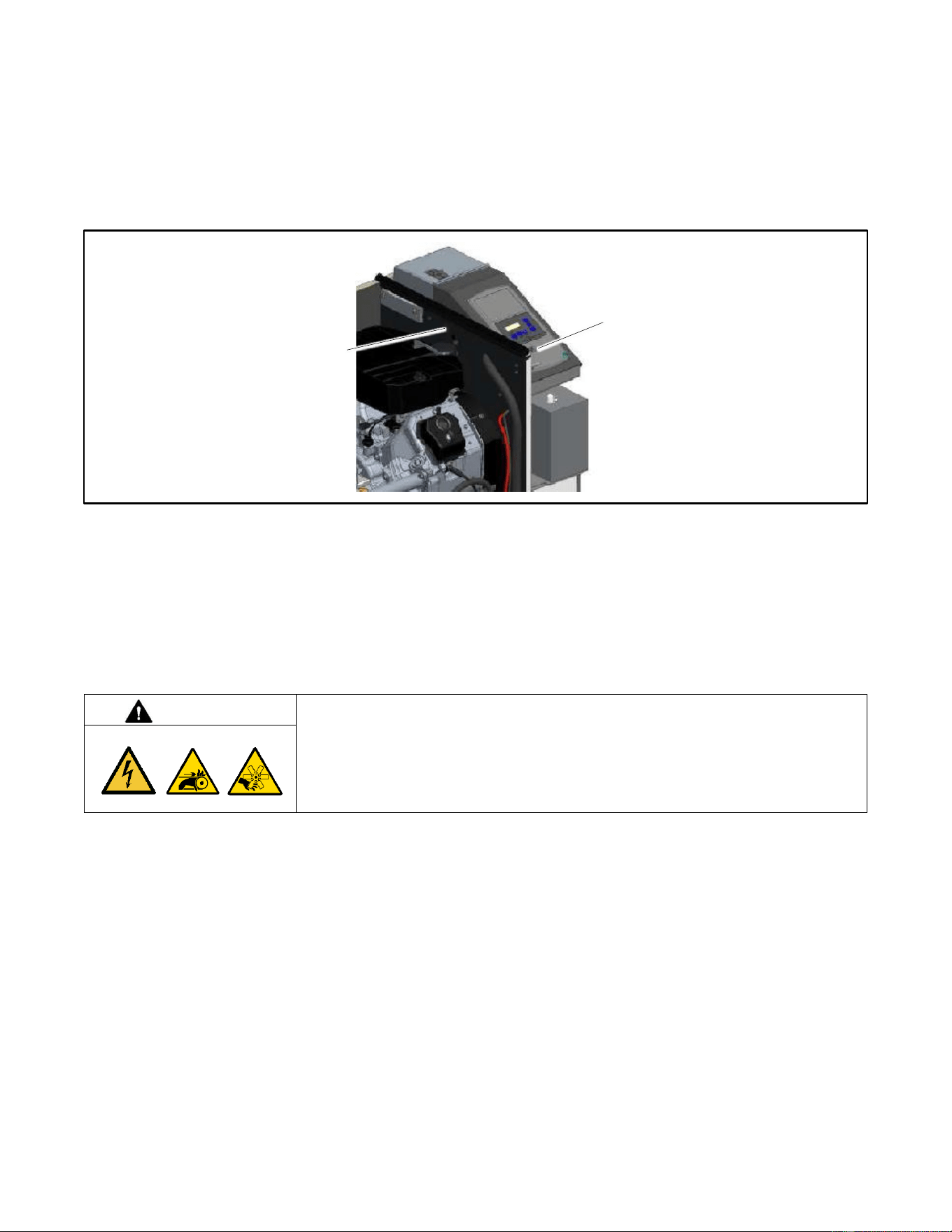
82 TP-7092 9/23
5.4 USB Port and Auxiliary Winding Mini-Breaker
The USB port is located under a small rubber cover as shown in Figure 66. The alternator winding circuit breaker is located on
the engine side of the bulkhead as shown in Figure 66.
A personal computer (laptop) with Kohler
®
SiteTech
TM
software can be used to view the event history and adjust controller
settings. Use a USB cable with a mini-B connector to connect the controller’s USB port to your PC.
See TP-6701, SiteTech
TM
Software Operation Manual, for software operation instructions.
Figure 66 USB Port and Mini-Breaker Locations
5.5 Stop Switches
The generator set may be equipped with an optional emergency stop switch or an engine shutdown switch. Verify that it is safe
to start the generator set and apply power to the load before deactivating these switches. See the Remote Emergency Stop
Switch section.
5.6 Thermostat
WARNING
Accidental starting.
Can cause severe injury or death.
Disconnect the battery cables before working on the generator set. Remove the
negative (–) lead first when disconnecting the battery. Reconnect the negative (–)
lead last when reconnecting the battery.
Disabling the generator set. Accidental starting can cause severe injury or death. Before working on the generator set or
equipment connected to the set, disable the generator set as follows: (1) Press the generator set off/reset button to shut down
the generator set. (2) Disconnect the power to the battery charger, if equipped. (3) Remove the battery cables, negative (–) lead
first. Reconnect the negative (–) lead last when reconnecting the battery. Follow these precautions to prevent the starting of the
generator set by the remote start/stop switch.
ADV-8928
Mini-breaker location (access through engine
compartment)
USB port on RDC2 controller
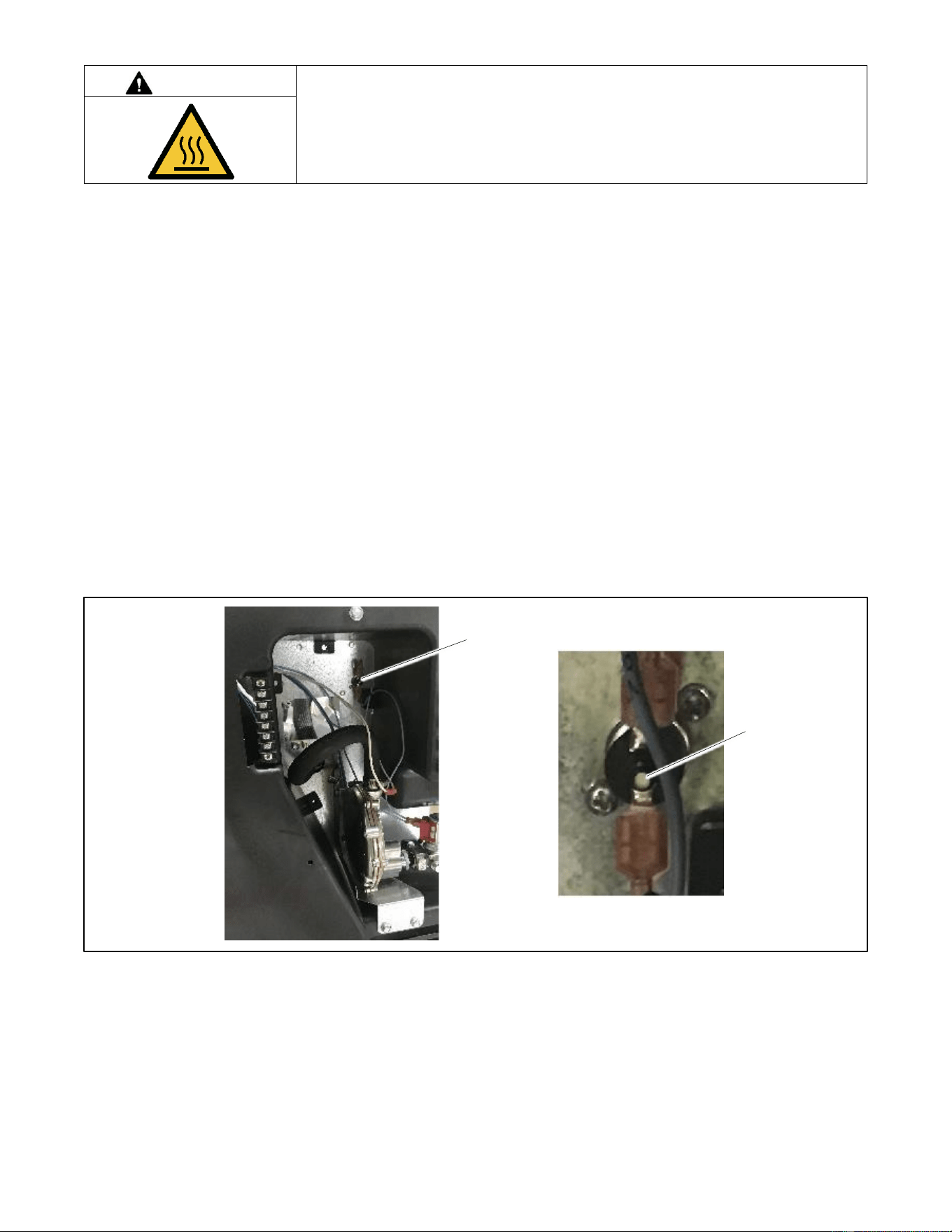
TP-7092 9/23 83
WARNING
Hot engine and exhaust system.
Can cause severe injury or death.
Do not work on the generator set until it cools.
Servicing the exhaust system. Hot parts can cause severe injury or death. Do not touch hot engine parts. The engine and
exhaust system components become extremely hot during operation.
The generator sets include a resettable thermostat. See Figure 67 for the thermostat location in the air intake area, near the fuel
system. The thermostat detects excess heat inside the enclosure. If the thermostat trips, the generator will shut down and the
controller will display a fault (underspeed, underfrequency, or undervoltage). Check for blocked air inlets and exhaust outlets.
Then follow these steps to reset the thermostat.
Procedure to Reset the Thermostat
1. Disconnect the utility power to the generator by opening (turning OFF) the corresponding circuit breaker at the building’s
distribution panel.
2. Open the enclosure roof and secure it with the roof stay on the left side of the enclosure.
3. Remove the air intake panel. See Figure 67.
4. Press the button on the thermostat to reset it.
5. Replace the air intake panel.
6. Reconnect utility power to the generator set by closing the circuit breaker in the distribution panel.
7. Reset the fault on the controller. Refer to the Faults section for instructions, if necessary.
Figure 67 Thermostat
Thermostat location
Thermostat reset
button

84 TP-7092 9/23
5.7 Troubleshooting
Figure 68 contains generator set troubleshooting, diagnostic, and repair information. Check for loose connections before
replacing parts.
Problem
Possible Cause
Corrective Action
Controller display
backlight is off.
Backlight turns off after about 1 minute with no activity.
Backlight will turn on when a button is pressed or the
generator set starts.
Controller display
is off.
Low or no battery voltage.
Check connections.
Check generator set battery. See the Service Views
section.
The generator set
does not crank.
Battery weak or dead.
Recharge or replace the battery. Make sure that the AC
power to the generator set controller is backed up by the
generator set.
Battery connections reversed or poor.
Check the connections.
Emergency stop switch activated.
Verify that it is safe to start the engine and apply load.
Then reset the stop switch or engine shutdown switch.
Fault shutdown.
Check the controller display for fault messages. Correct
the fault condition and reset the controller.
Generator set in the OFF mode.
Press the RUN button to start the engine or press AUTO to
allow remote starting.
Generator thermostat tripped.
Check for obstructed air inlets and outlets. Reset the
thermostat.
The generator set
cranks but does
not start, starts
hard, lacks
power, or
operates
erratically.
Air cleaner clogged.
Clean and/or replace the air cleaner.
Battery weak or dead.
Recharge or replace the battery.
Battery connection poor.
Clean and tighten the battery connections.
Spark plug wire connection loose.
Check the spark plug wires.
Low oil pressure shutdown.
Check for oil leaks. Check the oil level and add oil if
necessary.
Fuel pressure insufficient.
Check the fuel supply and valves.
Engine malfunction.
Contact an authorized Kohler dealer.
No AC output.
Line circuit breaker in the OFF position.
Place the circuit breaker in the ON position.
Line circuit breaker tripping because of overload.
Reduce the load on the generator set by unplugging non-
essential appliances.
Line circuit breaker tripping because of short circuit.
Contact an authorized Kohler dealer for service.
Auxiliary winding circuit breaker tripped.
Reset the circuit breaker (located in controller’s service
access area). Contact an authorized dealer for service if
breaker trips repeatedly.
Low output or
excessive drop in
voltage.
Generator set overloaded.
Reduce the load by unplugging non-essential appliances.
Generator set
stops suddenly.
Low oil pressure shutdown.
Check for oil leaks. Check the oil level and add oil if
necessary.
No fuel.
Check fuel valves and fuel supply.
Check enclosure thermostat and reset if tripped. Check
and clear air inlets and exhaust outlets.
Overcrank shutdown.
Reset the controller. If the overcrank fault occurs again,
contact an authorized Kohler dealer.
Auxiliary winding circuit breaker tripped.
Reset the auxiliary winding circuit breaker. Contact an
authorized dealer for service if breaker trips repeatedly.
Emergency stop switch activated.
Verify that it is safe to start the engine and apply load.
Then reset the stop switch or engine shutdown switch.
Fault shutdown.
Check the controller display for fault messages. Correct
the fault condition and reset the controller.
Generator set in the OFF mode.
Press the RUN button to start the engine or press AUTO to
allow remote starting.
Remote stop command received from a remote switch,
ATS, or OnCue
®
Plus.
Check the remote switch position. Check OnCue
®
Plus.
Generator thermostat tripped.
Check for obstructed air inlets and outlets. Reset the
thermostat.
Engine malfunction.
Contact an authorized Kohler dealer.
Figure 68 General Troubleshooting

TP-7092 9/23 85
Appendix A. Abbreviations
A, amp
ampere
blk. htr.
block heater
DAC
digital to analog converter
ABDC
after bottom dead center
BMEP
brake mean effective pressure
dB
decibel
AC
alternating current
bps
bits per second
dB(A)
decibel (A weighted)
A/D
analog to digital
br.
Brass
DC
direct current
ADC
advanced digital control;
analog to digital converter
BTDC
before top dead center
DCR
direct current resistance
adj.
adjust, adjustment
Btu
British thermal unit
DEF
diesel exhaust fluid
ADV
advertising dimensional drawing
Btu/min.
British thermal units per minute
deg., °
degree
AGM
absorbent glass mat
C
Celsius, centigrade
dept.
department
Ah
amp-hour
cal.
Calorie
dia.
Diameter
AHWT
anticipatory high water
temperature
CAN
controller area network
DI/EO
dual inlet/end outlet
AISI
American Iron and Steel Institute
CARB
California Air Resources Board
DIN
Deutsches Institut fur Normung e.
V. (also Deutsche Industrie
Normenausschuss)
ALOP
anticipatory low oil pressure
CAT5
Category 5 (network cable)
DIP
dual inline package
alt.
alternator
CB
circuit breaker
DPDT
double-pole, double-throw
Al
aluminum
CC
crank cycle
DPST
double-pole, single-throw
ANSI
American National Standards
Institute (formerly American
Standards Association, ASA)
cc
cubic centimeter
DS
disconnect switch
AO
anticipatory only
CCA
cold cranking amps
DVR
digital voltage regulator
APDC
Air Pollution Control District
ccw.
Counterclockwise
E2PROM,
EEPROM
electrically-erasable
programmable read-only memory
API
American Petroleum Institute
CEC
Canadian Electrical Code
E, emer.
emergency (power source)
approx.
approximate, approximately
cert.
certificate, certification, certified
EATS
Exhaust Aftertreatment System
APU
Auxiliary Power Unit
cfh
cubic feet per hour
ECM
electronic control module, engine
control module
AQMD
Air Quality Management District
cfm
cubic feet per minute
EDI
electronic data interchange
AR
as required, as requested
CG
center of gravity
EFR
emergency frequency relay
AS
as supplied, as stated, as
suggested
CID
cubic inch displacement
e.g.
for example (exempli gratia)
ASE
American Society of Engineers
CL
centerline
EG
electronic governor
ASME
American Society of Mechanical
Engineers
cm
centimeter
EGSA
Electrical Generating Systems
Association
assy.
Assembly
CMOS
complementary metal oxide
substrate (semiconductor)
EIA
Electronic Industries Association
ASTM
American Society for Testing
Materials
com
communications (port)
EI/EO
end inlet/end outlet
ATDC
after top dead center
coml
commercial
EMI
electromagnetic interference
ATS
automatic transfer switch
Coml/Rec
Commercial/Recreational
emiss.
Emission
auto.
Automatic
conn.
Connection
eng.
Engine
aux.
auxiliary
cont.
continued
EPA
Environmental Protection Agency
avg.
average
CPVC
chlorinated polyvinyl chloride
EPS
emergency power system
AVR
automatic voltage regulator
crit.
Critical
ER
emergency relay
AWG
American Wire Gauge
CRM
Common Rail Manifold
ES
engineering special, engineered
special
AWM
appliance wiring material
CSA
Canadian Standards Association
bat.
Battery
CT
current transformer
ESD
electrostatic discharge
BBDC
before bottom dead center
Cu
copper
est.
estimated
BC
battery charger, battery charging
cUL
Canadian Underwriter’s
Laboratories
E-Stop
emergency stop
BCA
battery charging alternator
cu. in.
cubic inch
etc.
et cetera (and so forth)
BCI
Battery Council International
cw.
Clockwise
exh.
exhaust
BDC
before dead center
CWC
city water-cooled
ext.
external
BHP
brake horsepower
cyl.
Cylinder
F
Fahrenheit, female
blk.
black (paint color), block (engine)
D/A
digital to analog
FDS
Fluid Dosing System

86 TP-7092 9/23
FHM
flat head machine (screw)
in.
inch
Lpm
liters per minute
fl. oz.
fluid ounce
in. H
2
O
inches of water
LOP
low oil pressure
flex.
flexible
in. Hg
inches of mercury
LP
liquefied petroleum
freq.
frequency
in. Lb.
inch pounds
LPG
liquefied petroleum gas
FS
full scale
Inc.
incorporated
LS
left side
ft.
foot, feet
ind.
Industrial
L
wa
sound power level, A weighted
ft. lb.
foot pounds (torque)
int.
internal
LWL
low water level
ft./min.
feet per minute
int./ext.
internal/external
LWT
low water temperature
ftp
file transfer protocol
I/O
input/output
m
meter, milli (1/1000)
g
gram
IP
internet protocol
M
mega (10
6
when used with SI
units), male
ga.
gauge (meters, wire size)
ISO
International Organization for
Standardization
m
3
cubic meter
gal.
gallon
J
joule
m
3
/hr.
cubic meters per hour
gen.
generator
JIS
Japanese Industry Standard
m
3
/min.
cubic meters per minute
genset
generator set
k
kilo (1000)
mA
milliampere
GFI
ground fault interrupter
K
kelvin
man.
manual
GND,
ground
kA
kiloampere
max.
maximum
gov.
governor
KB
kilobyte (2
10
bytes)
MB
megabyte (2
20
bytes)
gph
gallons per hour
KBus
Kohler communication protocol
MCCB
molded-case circuit breaker
gpm
gallons per minute
kg
kilogram
MCM
one thousand circular mils
gr.
grade, gross
kg/cm
2
kilograms per square
centimeter
meggar
megohmmeter
GRD
equipment ground
kgm
kilogram-meter
MHz
megahertz
gr. wt.
gross weight
kg/m
3
kilograms per cubic meter
mi.
mile
H x W x
D
height by width by depth
kHz
kilohertz
mil
one one-thousandth of an inch
HC
hex cap
kJ
kilojoule
min.
minimum, minute
HCHT
high cylinder head temperature
km
kilometer
misc.
miscellaneous
HD
heavy duty
kOhm,
kΩ
kilo-ohm
MJ
megajoule
HET
high exhaust temp., high
engine temp.
kPa
kilopascal
mJ
millijoule
hex
hexagon
kph
kilometers per hour
mm
millimeter
Hg
mercury (element)
kV
kilovolt
mOhm,
mΩ
milliohm
HH
hex head
kVA
kilovolt ampere
MOhm,
MΩ
megohm
HHC
hex head cap
kVAR
kilovolt ampere reactive
MOV
metal oxide varistor
HP
horsepower
kW
kilowatt
MPa
megapascal
hr.
hour
kWh
kilowatt-hour
mpg
miles per gallon
HS
heat shrink
kWm
kilowatt mechanical
mph
miles per hour
hsg.
Housing
kWth
kilowatt-thermal
MS
military standard
HVAC
heating, ventilation, and air
conditioning
L
liter
ms
millisecond
HWT
high water temperature
LAN
local area network
m/sec.
meters per second
Hz
hertz (cycles per second)
L x W x
H
length by width by height
mtg.
mounting
IBC
International Building Code
lb.
pound, pounds
MTU
Motoren-und Turbinen-Union
IC
integrated circuit
lbm/ft
3
pounds mass per cubic feet
MW
megawatt
ID
inside diameter, identification
LCB
line circuit breaker
mW
milliwatt
IEC
International Electrotechnical
Commission
LCD
liquid crystal display
µF
microfarad
IEEE
Institute of Electrical and
Electronics Engineers
LED
light emitting diode
µF
microfarad
IMS
improved motor starting
Lph
liters per hour

TP-7092 9/23 87
N, norm.
normal (power source)
PMG
permanent magnet generator
SCR
silicon controlled rectifier
(electrical), selective catalytic
reduction (exhaust emissions)
NA
not available, not applicable
pot
potentiometer, potential
s, sec.
second
nat. gas
natural gas
ppm
parts per million
SI
Systeme international d’unites,
International System of Units
NBS
National Bureau of Standards
PROM
programmable read-only
memory
SI/EO
side in/end out
NC
normally closed
psi
pounds per square inch
sil.
Silencer
NEC
National Electrical Code
psig
pounds per square inch gauge
SMTP
simple mail transfer protocol
NEMA
National Electrical
Manufacturers Association
pt.
pint
SN
serial number
NiCd
nickel cadmium
PTC
positive temperature coefficient
SNMP
simple network management
protocol
NFPA
National Fire Protection
Association
PTO
power takeoff
SPDT
single-pole, double-throw
Nm
newton meter
PVC
polyvinyl chloride
SPST
single-pole, single-throw
NO
normally open
PVC
polyvinyl chloride
spec
specification
no., nos.
number, numbers
PWM
pulse width modulated, pulse
width modulation
specs
specification(s)
NPS
National Pipe, Straight
qt.
quart, quarts
sq.
square
NPSC
National Pipe, Straight-coupling
qty.
quantity
sq. cm
square centimeter
NPT
National Standard taper pipe
thread per general use
R
replacement (emergency)
power source
sq. in.
square inch
NPTF
National Pipe, Taper-Fine
rad.
radiator, radius
SMS
short message service
NR
not required, normal relay
RAM
random access memory
SS
stainless steel
Ns
nanosecond
RDO
relay driver output
std.
standard
OC
overcrank
ref.
reference
stl.
Steel
OD
outside diameter
rem.
Remote
tach.
Tachometer
OEM
original equipment
manufacturer
Res/Co
ml
Residential/Commercial
TB
terminal block
OF
overfrequency
RFI
radio frequency interference
TCP
transmission control protocol
opt.
option, optional
RH
round head
TD
time delay
OS
oversize, overspeed
RHM
round head machine (screw)
TDC
top dead center
OSHA
Occupational Safety and Health
Administration
rly.
Relay
TDEC
time delay engine cooldown
OSHPD
Office of Statewide Health
Planning and Development
(California)
rms
root mean square
TDEN
time delay emergency to
normal
OV
overvoltage
rnd.
Round
TDES
time delay engine start
oz.
ounce
RO
read only
TDNE
time delay normal to
emergency
p., pp.
page, pages
ROM
read only memory
TDOE
time delay off to emergency
PC
personal computer
rot.
rotate, rotating
TDON
time delay off to normal
PCB
printed circuit board
rpm
revolutions per minute
temp.
temperature
pF
picofarad
RS
right side
term.
Terminal
PF
power factor
RTDs
resistance temperature
detectors
THD
total harmonic distortion
ph., ø
phase
RTU
remote terminal unit
TIF
telephone influence factor
PHC
Phillips
®
head Crimptiter
(screw)
RTV
room temperature vulcanization
tol.
Tolerance
PHH
Phillips
®
hex head (screw)
RW
read/write
turbo.
Turbocharger
PHM
pan head machine (screw)
SAE
Society of Automotive
Engineers
typ.
typical (same in multiple
locations)
PLC
programmable logic control
scfm
standard cubic feet per minute
UF
underfrequency

88 TP-7092 9/23
UHF
ultrahigh frequency
UIF
user interface
UL
Underwriter’s Laboratories, Inc.
UNC
unified coarse thread (was NC)
UNF
unified fine thread (was NF)
univ.
universal
URL
uniform resource locator (web
address)
US
undersize, underspeed
UV
ultraviolet, undervoltage
V
volt
VAC
volts alternating current
VAR
voltampere reactive
VDC
volts direct current
VFD
vacuum fluorescent display
VGA
video graphics adapter
VHF
very high frequency
W
watt
WCR
withstand and closing rating
w/
with
WO
write only
w/o
without
wt.
weight
xfmr
transformer

TP-7092 9/23 89

90 TP-7092 9/23


TP-7092 9/23e
Original Instructions (English)
© 2018 Kohler Co. All rights reserved.
KOHLER CO. Kohler, Wisconsin 53044
Phone 920-457-4441, Fax 920-459-1646
For the nearest sales/service outlet in the
US and Canada, phone 1-800-544-2444
KOHLERPower.com