

‘65 TWIN REVERB
®
ENGLISH - PAGES ...........6-7
ESPAÑOL - PAGINAS ........8-9
FRANÇAIS - PAGES ..........10-11
ITALIANO - PAGINE .........12-13
DEUTSCH - SEITEN ..........14-15
.............16-17
IMPORTANT SAFETY INSTRUCTIONS
The lightning flash with arrowhead symbol within an equilateral triangle is intended
to alert the user to the presence of uninsulated “dangerous voltage” within the
product’s enclosure that may be of sufficient magnitude to constitute a risk of electric
shock to persons.
The exclamation point within an equilateral triangle is intended to alert the user to
the presence of important operating and maintenance (servicing) instructions in the
literature accompanying the product.
1) Read these instructions.
2) Keep these instructions.
3) Heed all warnings.
4) Follow all instructions.
5) Do not use this apparatus near water.
6) Clean only with dry cloth.
7) Do not block any ventilation openings. Install in accordance with the manufacturer’s
instructions.
8) Do not install near any heat sources such as radiators, heat registers, stoves, or other
apparatus (including amplifiers) that produce heat.
9) Do not defeat the safety purpose of the polarized or grounding-type plug. A polarized plug
has two blades with one wider than the other. A grounding type plug has two blades and
a third grounding prong. The wide blade or the third prong are provided for your safety. If
the provided plug does not fit into your outlet, consult an electrician for replacement of the
obsolete outlet.
10) Protect the power cord from being walked on or pinched particularly at plugs, convenience
receptacles and the point where they exit from the apparatus.
11) Only use attachments/accessories specified by the manufacturer.
12) Use only with the cart, stand, tripod, bracket, or table specified by the
manufacturer or sold with the apparatus. When a cart is used, use caution
when moving the cart/apparatus combination to avoid injury from tip-
over.
13) Unplug this apparatus during lightning storms or when unused for long
periods of time.
14) Refer all servicing to qualified service personnel. Servicing is required when the apparatus
has been damaged in any way, such as power-supply cord or plug is damaged, liquid has
been spilled or objects have fallen into the apparatus, the apparatus has been exposed to
rain or moisture, does not operate normally, or has been dropped.
15) To completely disconnect this apparatus from the AC mains, disconnect the power supply
cord plug from the AC receptacle.
16) The mains plug of the power supply cord shall remain readily operable.
17) WARNING – To reduce the risk of fire or electric shock, do not expose this apparatus to rain
or moisture.
18) Do not expose this equipment to dripping or splashing and ensure that no objects filled with
liquids, such as vases, are placed on the equipment.
19) Maintain at least 6 inches (15.25 cm) of unobstructed air space behind the unit to allow for
proper ventilation and cooling of the unit.
20) CAUTION – For rack mounted power amplifiers, keep all wiring and materials away from
the sides of the unit and allow the unit to cool down for 2 minutes before pulling from a rack
enclosure.
21) Amplifiers and loudspeaker systems, and ear/headphones (if equipped) are capable of
producing very high sound pressure levels which may cause temporary or permanent
hearing damage. Use care when setting and adjusting volume levels during use.
22) FCC Part 15 Compliance Statement (for digital products, as applicable) - Part 15.21: Changes
or modifications not expressly approved by the party responsible for compliance could void
the user’s authority to operate the equipment. NOTE: The manufacturer is not responsible
for any radio or TV interference caused by unauthorized modifications to this equipment.
Such modifications could void the user’s authority to operate the equipment.
23) WARNING – To maintain product safety, products with internal or external (battery pack)
batteries: •Batteries and/or the product in which they are installed, shall not be exposed to
excessive heat such as sunshine, fire or the like. •There may be a danger of explosion if the
battery is incorrectly connected/replaced. Replace only with the same or equivalent type
battery specified in the instructions or on the product.
24) CAUTION – Unplug unit and allow it to cool before touching/ replacing vacuum tubes.
CONSIGNES DE SÉCURITÉ IMPORTANTES
Ce symbole avertit l'utilisateur de la présence d’une tension dangereuse non isolée dans
le boîtier du produit, qui peut être suffisamment importante pour constituer un risque
d'électrocution.
Le symbole du point d’exclamation dans un triangle équilatéral avertit l’utilisateur de la
présence d’instructions importantes relatives au fonctionnement et à l'entretien dans la
documentation qui accompagne le produit.
1) Lisez ces instructions.
2) Conservez ces instructions.
3) Respectez toutes les mises en garde.
4) Suivez toutes les instructions.
5) N’utilisez pas cet appareil à proximité d’un point d’eau.
6) Nettoyez-le uniquement avec un chiffon sec.
7) Ne bloquez pas les ouvertures de ventilation. Installez l'appareil en suivant les instructions du
fabricant.
8) Ne l’installez pas à proximité d’une source de chaleur, comme un radiateur, un four ou tout
autre appareil (incluant les amplificateurs) produisant de la chaleur.
9) Ne modifiez pas la fiche polarisée (Canada) ou la mise à la terre. Les fiches polarisées possèdent
deux lames, dont l’une est plus large que l’autre. Les fiches avec mise à la terre possèdent deux
broches plus une broche de terre. La lame plus large et la terre sont des éléments de sécurité.
Si la fiche ne correspond pas à votre prise secteur, contactez un électricien pour la faire
remplacer.
10) Évitez de marcher sur le cordon secteur ou de le pincer, en particulier au niveau des fiches, des
prises secteur et de l'embase de l’appareil.
11) Utilisez uniquement les pièces/accessoires spécifiés par le fabricant.
12) Utilisez uniquement le chariot, le support, le trépied, la console ou la table
spécifiés par le fabricant ou vendus avec l’appareil. Lorsqu'un chariot est
utilisé, prenez toutes les précautions nécessaires pour éviter les chutes lors
du déplacement de l’ensemble chariot-appareil.
13) Déconnectez l’appareil pendant les orages ou les longues périodes
d'inutilisation.
14) Confiez toutes les réparations à un technicien qualifié. Vous devez faire contrôler cet appareil
s'il a été endommagé de quelque façon que ce soit, comme lorsque le cordon secteur ou les
fiches sont endommagés, qu'un liquide ou des objets se sont infiltrés dans l’appareil, qu'il a été
exposé à la pluie ou l’humidité, qu'il a subi un choc ou qu'il ne fonctionne pas normalement.
15) Pour déconnecter entièrement l’appareil du secteur (phase, neutre et terre), déconnectez la
fiche du cordon secteur de la prise.
16) La fiche du cordon secteur doit demeurer accessible en tout temps.
17) MISE EN GARDE – Pour réduire les risques d’incendie ou d'électrocution, n’exposez pas cet
appareil aux intempéries ou à l'humidité.
18) N’exposez pas cet appareil à l’humidité ou aux projections liquides. Ne posez pas de récipient
rempli de liquide, tel qu'un vase, sur cet appareil.
19) Maintenez un espace d’au moins 15 cm (6 pouces) à l'arrière de l'appareil pour laisser circuler
l’air et permettre une ventilation et un refroidissement convenables.
20) ATTENTION – Pour les amplificateurs de puissance montés en Rack, ne placez pas de câbles
et matériaux à proximité des côtés de l’appareil. Laissez l'appareil refroidir pendant 2 minutes
avant de le retirer du Rack.
21) Les amplificateurs, les haut-parleurs, les enceintes, les casques et écouteurs (selon le cas)
peuvent produire des niveaux sonores très élevés qui peuvent causer des dommages auditifs
temporaires ou permanents. Réglez le volume avec modération.
22) Norme fédérale US FCC Part 15 (pour les produits numériques répondant aux descriptions)
- alinéa 15.21 : Les changements ou modifications non approuvées officiellement par
l'organisation ou la société responsable de la conformation à la norme peuvent annuler le
droit de l'utilisateur à se servir du produit. REMARQUE : le fabricant n'est pas responsable des
interférences radio ou TV causées par les modifications non-autorisées apportées au matériel.
Ces modifications peuvent annuler le droit de l'utilisateur à se servir du produit.
23) MISE EN GARDE – Pour éviter d'endommager les produits munis de piles internes ou
externes : • Les piles et/ou le produit dans lequel elles sont installées ne doivent pas être
exposés à une chaleur excessive, comme les rayons du soleil, le feu, etc. • Il y a un risque
d’explosion lorsque la pile n’est pas correctement connectée/remplacée. Remplacez-la
uniquement par une pile de type identique ou équivalent, spécifié dans les instructions ou sur
le produit.
24) ATTENTION – Déconnectez l'appareil du secteur et laissez-le refroidir avant de toucher ou de
remplacer les lampes.
INSTRUCCIONES DE SEGURIDAD IMPORTANTES
El relámpago con el símbolo de cabeza de flecha dentro de un triángulo equilátero
tiene por objeto alertar al usuario de la presencia de “voltaje peligroso” no aislado
dentro del gabinete del producto, que puede ser de magnitud suficiente como para
constituir un riesgo de descarga eléctrica para las personas.
El signo de admiración dentro de un triángulo equilátero tiene por objeto alertar al
usuario a la presencia de importantes instrucciones de operación y mantenimiento
(servicio) en los documentos que acompañan al producto.
1) Lea estas instrucciones.
2) Conserve estas instrucciones.
3) Atienda todas las advertencias.
4) Siga todas las instrucciones.
5) No use este aparato cerca del agua.
6) Limpie sólo con un paño seco.
7) No bloquee ningún orificio de ventilación. Instale de acuerdo con las instrucciones del
fabricante.
8) No lo instale cerca de ninguna fuente de calor, como radiadores, registros de calefacción,
estufas u otros aparatos (incluidos los amplificadores) que produzcan calor.
9) No elimine el objetivo de seguridad de la clavija polarizada o con conexión a tierra. Una clavija
polarizada tiene dos hojas, una de ellas más ancha que la otra. Una clavija con conexión a tierra
tiene dos hojas y una tercera pata de tierra. La hoja ancha o la tercera pata se suministran para
su seguridad. Si la clavija suministrada no encaja en su enchufe, consulte a un electricista para
que reemplace el enchufe obsoleto.
10) Proteja el cable de alimentación para que no sea pisado o pellizcado, especialmente en las
clavijas, receptáculos de conveniencia y en el punto en el que salen del aparato.
11) Use únicamente aditamentos o accesorios especificados por el fabricante.
12) Úselo únicamente con el carrito, soporte, trípode, abrazadera o mesa
especificados por el fabricante o que se venden con el aparato. Cuando se use
un carrito, sea precavido al mover la combinación de carrito y aparato para
evitar lesiones por volcadura.
13) Desenchufe este aparato durante las tormentas eléctricas o cuando no se use
durante períodos prolongados de tiempo.
14) Refiera todo el servicio a personal cualificado. Se requiere servicio cuando el aparato se ha
dañado de cualquier forma, como si se dañan el cable de alimentación o la clavija, si se ha
vertido un líquido o han caído objetos al interior del aparato, si el aparato ha estado expuesto
a la lluvia o la humedad, no funciona normalmente o ha caído.
15) Para desconectar completamente este aparato de la red de CA, desconecte el cable de
alimentación eléctrica del receptáculo de CA.
16) La clavija eléctrica del cable de alimentación se mantendrá fácilmente operativa.
17) ADVERTENCIA – Para reducir el riesgo de incendio o descarga eléctrica, no exponga este
aparato a la lluvia o la humedad.
18) No exponga este equipo a escurrimientos o salpicaduras, y asegúrese de que no se coloquen
objetos llenos de líquido, como jarrones, sobre el equipo.
19) Mantenga al menos 6 pulgadas (15.25 cm) de espacio de ventilación sin obstrucciones detrás
de la unidad para permitir su ventilación y enfriamiento adecuados.
20) PRECAUCIÓN – En el caso de amplificadores de potencia montados en anaqueles, conserve
todo el cableado y materiales alejados de los lados de la unidad y permita que la unidad se
enfríe durante 2 minutos antes de retirarla de un gabinete de anaquel.
21) Los amplificadores, sistemas de altavoces y auriculares (sea cual sea el dispositivo con el que esté
equipada la unidad) son capaces de producir niveles de presión sonora muy elevados que pueden llegar
a producir problemas de sordera tanto temporal como crónica. Tenga mucho cuidado a la hora de ajustar
los niveles de volumen al usar este aparato.
22) Certificación de cumplimiento de la sección 15 de las normas FCC (para dispositivos digitales,
según sea aplicable en cada caso) - Sección 15.21: Los cambios o modificaciones que no hayan
sido autorizados expresamente y por escrito por la empresa responsable del cumplimiento de
estas normas pueden anular la autorización del usuario para seguir utilizando este aparato.
NOTA: El fabricante no será responsable de ninguna interferencia en radio o TV que sea
producida por modificaciones no autorizadas en este aparato. Tal tipo de modificaciones
pueden anular la autorización del usuario para seguir utilizando este aparato.
23) ADVERTENCIA – Para mantener la seguridad de los productos con baterías internas o externas
(paquete de baterías): •Las baterías y el producto en el que están instaladas no deberán
exponerse a calor excesivo, como la luz del sol, fuego y similares. •Puede haber peligro de
explosión si la batería se conecta o reemplaza de modo incorrecto. Reemplácelas sólo con
baterías del mismo tipo o equivalente especificadas en las instrucciones o en el producto.
24) PRECAUCIÓN – Desconecte esta unidad de la corriente y espere un rato hasta que se refrigere
antes de tocar / sustituir las válvulas.
WICHTIGE ANWEISUNGEN ZU IHRER SICHERHEIT
Das Symbol Blitz und Pfeil in einem gleichseitigen Dreieck soll den Benutzer vor dem
Vorhandensein nicht isolierter „gefährlicher Spannung“ im Gehäuse des Produkts
warnen, die möglicherweise hoch genug ist, um ein Stromschlagrisiko darzustellen.
Das Ausrufezeichen in einem gleichseitigen Dreieck soll den Benutzer auf wichtige
Bedienungs- und Wartungsanweisungen (Serviceanweisungen) in den dem Produkt
beiliegenden Broschüren aufmerksam machen.
1) Lesen Sie diese Anweisungen.
2) Bewahren Sie diese Anweisungen auf.
3) Beachten Sie alle Warnhinweise.
4) Befolgen Sie alle Anweisungen.
5) Benutzen Sie die Vorrichtung nie in der Nähe von Wasser.
6) Nur mit trockenem Tuch reinigen.
7) Belüftungsöffnungen nicht blockieren. Den Anweisungen des Herstellers entsprechend
installieren.
8) Installieren Sie die Vorrichtung nicht in der Nähe von Wärmequellen wie Radiatoren,
Heizkörpern, Herden oder anderen Geräten (insbesondere Verstärkern), die Wärme erzeugen.
9) Achten Sie darauf, den Sicherheitszweck des verpolungssicheren oder geerdeten Steckers
nicht zu umgehen. Ein verpolungssicherer Stecker ist mit zwei flachen Stiften ausgestattet,
von denen einer breiter ist als der andere. Ein geerdeter Stecker ist mit zwei Stiften und einer
Erdbuchse ausgestattet. Der breitere Stift oder die Erdbuchse dienen Ihrer Sicherheit. Sollte
der mitgelieferter Stecker nicht in Ihre Steckdose passen, wenden Sie sich zum Austausch der
veralteten Steckdose an einen Elektriker.
10) Schützen Sie das Stromkabel davor, dass darauf getreten oder dass es besonders am Stecker, an
Steckerleisten oder an der Austrittsstelle aus dem Gerät geknickt wird.
11) Verwenden Sie nur vom Hersteller zugelassenes Zubehör.
12) Benutzen Sie das Gerät nur mit den vom Hersteller festgelegten oder gemeinsam
mit dem Gerät verkauften Wagen, Ständern, Stativen, Halterungen oder Tischen.
Achten Sie bei Benutzung eines Wagens darauf, dass das gemeinsam mit dem Wagen
bewegte Gerät nicht kippt und zu Verletzungen führt.
13) Ziehen Sie bei Gewittern oder bei längeren Stillstandzeiten den Netzstecker
des Geräts.
14) Überlassen Sie alle Wartungsarbeiten qualifiziertem Personal. Ein Service wird erforderlich,
wenn das Gerät in irgendeiner Weise beschädigt wurde, beispielsweise bei Beschädigung des
Netzsteckers oder des Netzkabels, wenn Flüssigkeiten über das Gerät vergossen wurden oder
Gegenstände in das Gerät gefallen sind, das Gerät Regen oder Feuchtigkeit ausgesetzt war,
nicht ordnungsgemäß funktioniert oder fallen gelassen wurde,
15) Ziehen Sie den Netzstecker aus der Steckdose, um das Gerät vollständig vom Wechselstromnetz
zu trennen.
16) Der Netzstecker des Netzkabels muss jederzeit betriebsbereit sein.
17) WARNHINWEIS: Um die Gefahr vom Feuer oder Stromschlag zu vermeiden, darf das Gerät
nicht Regen oder Feuchtigkeit ausgesetzt werden.
18) Lassen Sie nicht zu, dass Flüssigkeiten auf das Gerät tropfen oder gespritzt werden können,
und achten Sie darauf, dass keine mit Wasser gefüllten Gegenstände wie Vasen auf das Gerät
gestellt werden.
19) Achten Sie auf mindestens 15 cm Abstand hinter dem Gerät für die ungehinderte Luftzirkulation
und Kühlung des Geräts.
20) VORSICHT: Bei in Regalen (Racks) montierten Verstärkern ist die gesamte Verkabelung
und sämtliches Material von den Seiten des Gerätes fernzuhalten; lassen Sie das Gerät vor
Entnahme aus dem Rack zwei Minuten lang abkühlen.
21) Verstärker, Lautsprechersysteme und Ohr/Kopfhörer (falls getragen) können sehr hohe Schalldruckpegel
erzeugen und dadurch vorübergehende oder dauerhafte Hörschäden verursachen. Gehen Sie vorsichtig
vor, wenn Sie während des Betriebs die Lautstärkepegel einstellen oder nachregeln.
22) FCC Konformitätserklärung Teil 15 (für Digitalprodukte, nach Anwendbarkeit) - Teil 15.21:
Änderungen oder Modifikationen, die nicht ausdrücklich von der für die Konformität
verantwortlichen Stelle genehmigt wurden, können zu einem Betriebsverbot führen.
HINWEIS: Der Hersteller ist nicht verantwortlich für Radio- oder TV-Interferenzen, die durch
unautorisierte Modifikationen an diesem Gerät verursacht werden. Derartige Modifikationen
können zu einem Betriebsverbot führen.
23) WARNHINWEIS: Zur Aufrechterhaltung der Sicherheit von mit internen oder externen
Batterien (Akkumulatoren) betriebenen Produkten ist folgendes zu beachten: • Die Batterien
sowie das Produkt, in dem sie installiert sind, dürfen keiner übermäßigen Hitze (durch
Sonneneinstrahlung, Feuer usw.) ausgesetzt werden. • Bei unsachgemäßem Anschluss/
Austausch der Batterien besteht Explosionsgefahr. Der Austausch darf nur mit Batterien
des gleichen oder gleichwertigen Typs erfolgen, der in den Anweisungen oder am Produkt
angegeben ist.
24) VORSICHT – Ziehen Sie den Netzstecker und lassen Sie das Gerät abkühlen, bevor Sie die
Vakuumröhren berühren/ersetzen.
IMPORTANTI NORME DI SICUREZZA
Il simbolo del fulmine con la punta a freccia, racchiuso in un triangolo
equilatero, avverte l’utente della presenza di tensione pericolosa non isolata
all’interno del prodotto, sufficiente a costituire un rischio di shock elettrico
per le persone.
Il punto esclamativo all’interno di un triangolo equilatero avvisa l’utente
della presenza di importanti istruzioni per il funzionamento e la
manutenzione incluse nel materiale informativo che accompagna il
prodotto.
1) Leggere queste istruzioni.
2) Conservare queste istruzioni.
3) Rispettare tutte le avvertenze.
4) Seguire tutte le istruzioni.
5) Non usare questo apparecchio vicino all’acqua.
6) Pulire unicamente con un panno asciutto.
7) Non ostruire le prese di aerazione. Installare secondo le istruzioni fornite dal
costruttore.
8) Non installare vicino a fonti di calore come caloriferi, diffusori di calore, stufe o altri
dispositivi che producono calore (inclusi gli amplificatori).
9) Non annullare la sicurezza garantita dalla spina polarizzata o con messa a terra. Le
spine polarizzate sono caratterizzate da due lamine, di cui una più grande dell’altra.
Le spine con messa a terra dispongono di due lame e di un terzo polo per la messa a
terra. La lamina grande o il terzo polo sono contemplati per garantire la sicurezza. Se
la spina del cavo fornito in dotazione non si adatta alla presa, consultare un elettricista
per sostituire la presa obsoleta.
10) Proteggere il cavo di alimentazione perché non venga calpestato, tirato o piegato, in
particolare vicino alla presa e al punto in cui il cavo esce dal dispositivo.
11) Usare solo accessori/componenti specificati dal costruttore.
12) Usare solo carrelli, supporti, treppiedi, staffe o tavoli specificati dal
costruttore o venduti con l’apparecchio. Quando si usa un carrello, fare
attenzione nello spostare la combinazione carrello/apparecchio per
evitare lesioni causate dal ribaltamento.
13) Scollegare il dispositivo durante i temporali con fulmini o in caso di
lunghi periodi di inutilizzo.
14) Per l’assistenza tecnica rivolgersi sempre a personale qualificato. È necessaria
l’assistenza quando il dispositivo risulta danneggiato in qualunque modo (ad
esempio: cavo di alimentazione o spina danneggiati, liquido versato o oggetti caduti
nel dispositivo, dispositivo esposto a pioggia o umidità, funzionamento non normale
o dispositivo caduto).
15) Per scollegare completamente l’apparecchio dalla presa di rete CA togliere la spina del
cavo di alimentazione dalla presa CA.
16) La spina di rete del cavo di alimentazione deve essere sempre facilmente accessibile e
operabile.
17) AVVERTENZA - Per ridurre il rischio di incendio o di shock elettrico, non esporre
questo apparecchio alla pioggia o all’umidità.
18) Non esporre il dispositivo a sgocciolamenti o a spruzzi di alcun liquido ed assicurarsi
che nessun oggetto contenente liquidi, come vasi, venga collocato su di esso.
19) Lasciare almeno 15 cm di spazio libero dietro al dispositivo per consentire una corretta
aerazione e il raffreddamento dell'unità.
20) ATTENZIONE- Per gli amplificatori di potenza montati all'interno di un rack,
mantenere tutti i cavi e gli oggetti lontano dai fianchi laterali del dispositivo e, prima
di estrarlo dal rack-case, lasciarlo raffreddare per 2 minuti.
21) Gli amplificatori, i sistemi di altoparlanti e le cuffie/dispositivi in-ear (se presenti) possono
generare livelli audio con un'elevata pressione sonora, in grado di causare danni temporanei
o permanenti all'udito. Quindi, durante l'uso è opportuno prestare molta attenzione
nell'impostazione e regolazione dei livelli di volume.
22) Dichiarazione di Conformità FCC Parte 15 (per prodotti digitali, se applicabile) -
Parte 15.21: Le modifiche non espressamente approvate dalla parte responsabile alla
conformità può annullare l'autorità dell'utente di operare con il dispositivo. NOTA: Il
costruttore non è da ritenersi responsabile per qualsiasi interferenza radio o TV causata
da modifiche non autorizzate del dispositivo in oggetto. Tali modifiche possono annullare
l'autorità dell'utente di operare con il dispositivo.
23) AVVERTENZA – Per preservare la sicurezza dell'unità, prodotti con batterie interne
o esterne (battery-pack): • Le batterie e/o il prodotto in cui queste sono installate
non devono essere esposti a calore eccessivo, come luce solare, fuoco o simili. • Se
la batteria viene collegata/sostituita in modo non corretto può sussistere il rischio
di esplosione. Sostituire solo con batterie dello stesso tipo o equivalente, come
specificato nelle istruzioni o sul prodotto.
24) CAUTELA - Prima di toccare/sostituire le valvole, disconnettere l'unità e lasciarla
raffreddare.
安全にご 使 用いただくために
二等辺三角形の中の矢印のついた稲妻の閃光のシンボルは、人
に電気ショックを与えるに十分な、絶縁されていない「高電圧の
危険」が製品のケース内にあることを警告するものです。
二等辺三角形の中の感嘆符合は、重要な操作方法およびメンテ
ナンス方法の記述が製品に付属の説明書にあることを示します。
1) 以下の説明をお読みください。
2) 本 説 明 書 を 保 存 してくださ い 。
3) 警告にはすべて注意してください。
4) 使用方法にはすべて従ってください。
5) 本装置は水の近くでは使用しないでください。
6) 清掃は、乾いた布でのみ行ってください。
7) 通気孔はふさがないでください。製造元の手順書に従って設置してく
ださい。
8) ラジエーター、ヒート レジスター、調理用コンロ、音響用アンプリファ
イア等の、熱を発する機器の近くには設置しないでください。
9) 極性プラグや接地プラグの安全機能を妨げないようにしてください。
極性プラグは二つのブレードの一方が他方より幅広くなっています。接
地型プラグには、二つのブレードに加えて接地プロングがあります。幅
の広いブレードまたは3番目のプロングは、安全用です。プラグがコン
セントに合わないときは、電気技師に相談して旧式のコンセントを付
け 替 えてくだ さ い 。
10) 電 源 コ ー ド が 踏 ま れ た り 、特 に プ ラ グ 、便 利 レ セ プ タ ク ル 、ま た は 装 置
か ら 出 てくる箇 所 で ねじ れ な いよう に 保 護してくださ い 。
11) メーカー指定の付属品/アクセサリーのみを使用してくだ
さい。
12) カ ー ド 、ス タ ン ド 、三 脚 、ブ ラ ケ ッ ト 、テ ー ブ ル は 、メ ー カ ー
指定のもの、または装置と共に販売されているもののみ
を 使 用してください。カートをご 使 用 の 場 合 は 、カ ートと
装置を一緒に移動させるとき、転倒によって怪我をされな
いようご 注 意ください。
13) 稲妻が光っている間、また長期間ご使用にならないときは、本装置の
電 源 をプラグか ら 抜 いてくだ さ い 。
14) メンテナンスは すべて、資 格 のあるメンテナン スサービス要員に依 頼
してください。メンテナンスは装置が何らかの形で損傷した場合、例え
ば次のような場合に必要となります: 電源コードまたはプラグが損
傷した場合、装置の中に液体がこぼれて入ったり、ものが落ちて入った
りした場合、装置が雨や湿気にさらされた場合、装置が正常に動作し
ない場合、装置を落とした場合。
15) 本装置をAC主電源から完全に切り離すには、電源コードのプラグを
A C コンセントから 抜 いてくだ さ い 。
16) 電源コードの電源プラグは、常に操作可能な状態にしておいてくださ
い。
17) 警告 - 火災や電気ショックの危険を減らすため、本装置を雨や湿気
に さらさな いよう にしてくださ い 。
18) 本装置を水のしずくや水はねにさらさないでください。また、花瓶など
の水の入ったものは本装置の上には絶対に置かないようにしてくださ
い。
19) 本装置ユニットの適切な通気および冷却のため、その背後に少なくと
も15.5cmのスペースを確保し、そこにはさえぎるようなものは置かな
いよう にしてくださ い 。
20) 注意-ラックに搭載したパワーアンプリファイアの場合は、配線そ
の他をユニットの側面から離しておいてください。また、ラックのケー
ス か ら ユ ニットを 取り出 す 前 に ユ ニット を2 分 間 冷 却 させ てくだ さ い 。
21) ア ン プ リファイヤー 、ラ ウド スピー カ ー シ ス テムとイヤ フォン/ ヘッド フォン( 必
要な場合)は、非常に大きな音圧レベルを生成し、一時的または恒久的な聴
覚のダメージの原因となる場合があります。使用中のボリューム•レベルの設定
と調 整 に は 注 意 が 必 要で す。
22) FCCPart 15 適合宣言(デジタル製品、規定の通り)–Part 15.21: 順守の責任を持つ団体
によって明示的に許可されていない変更や改造は、ユーザーの機器を操作する権限を
無効にする場合があります。注意: 製造者は機器に施された未認証の改造によって引き
起こされた、あらゆるラジオまたはテレビの障害については、責任を有しません。この種
の改造はユーザーの機器を操作する権限を無効にする場合があります。
23) 警告 - 安 全確保のため、バッテリーを内臓した、または外部バッテリ
ー(バッテリーパック)を使用した製品をご使用の際は、次のことにご
注意ください: * バッテリーおよび/またはバッテリーが入った製
品は、太陽光線、火、等の過度の熱にはさらさないでください。* バ
ッテリーの接続/交換方法を誤ると、爆発の危険性があります。交換す
るときは、説明書または製品上に記載されたものと同じか、同等の種
類のバッテリーのみを 使 用してください。
24) 注意 –
真空管に触る/交換する前に、製品をコンセントから抜き冷却させてくだ
さい。
INSTRUÇÕES DE SEGURANÇA IMPORTANTES
O relâmpago com símbolo de cabeça de flecha dentro de um triângulo
equilátero destina-se a alertar o utilizador para a presença de “tensão perigosa”
dentro da estrutura do produto que pode ter magnitude suficiente para
representar um risco de choque eléctrico para as pessoas.
O ponto de exclamação dentro do triângulo equilátero destina-se a alertar o
utilizador para a presença de instruções de funcionamento e manutenção
(assistência técnica) na documentação que acompanha o produto.
1) Leia estas instruções.
2) Guarde estas instruções.
3) Cumpra todas as advertências.
4) Siga todas as instruções.
5) Não utilize este aparelho próximo de água.
6) Limpe apenas com um pano seco.
7) Não bloqueie quaisquer orifícios de ventilação. Instale de acordo com as instruções do
fabricante.
8) Não instale próximo de fontes de calor, tais como radiadores, saídas de ar quente,
fogões ou outros aparelhos (incluindo amplificadores) que produzam calor.
9) Não anule a finalidade de segurança da ficha polarizada ou de ligação à terra. Uma
ficha polarizada possui duas lâminas, sendo uma delas mais larga do que a outra.
Uma ficha de ligação à terra possui duas lâminas e um terceira ponta de ligação à
terra. A lâmina larga ou a terceira ponta são fornecidas para sua segurança. Se a ficha
fornecida não couber na sua tomada, consulte um electricista para substituir a tomada
obsoleta.
10) Proteja o cabo de alimentação eléctrica do aparelho para que não seja pisado ou
dobrado especialmente nas fichas, nos receptáculos ou no ponto onde o cabo sai do
aparelho.
11) Utilize apenas acessórios/peças especificados pelo fabricante.
12) Utilize o aparelho apenas com o carrinho, suporte, tripé ou mesa
especificados pelo fabricante ou vendidos com o aparelho. Quando
utilizar um carrinho, tenha cuidado ao deslocar a combinação
carrinho/aparelho para evitar ferimentos provocados por uma
possível queda.
13) Desligue este aparelho durante trovoadas ou quando não for utilizá-lo por um longo
período de tempo.
14) Solicite todas as reparações a pessoal de assistência qualificado. É necessária
assistência técnica quando o aparelhos se tiver danificado de alguma forma como,
por exemplo, o cabo de alimentação ou a ficha estão danificados, foram derramados
líquidos ou caíram objectos para dentro do aparelho, o aparelho esteve exposto a
chuva ou humidade, o aparelho não funciona normalmente ou sofreu uma queda.
15) Para desligar por completo este aparelho da corrente eléctrica de CA, desligue a ficha
do cabo de alimentação do receptáculo de CA.
16) A ficha eléctrica do cabo de alimentação irá permanecer pronta a funcionar.
17) ADVERTÊNCIA – Para reduzir o risco de incêndio ou choque eléctrico, não exponha
este aparelho a chuva ou humidade.
18) Não exponha este equipamento a gotejamento ou salpicos e certifique-se de que não
são colocados objectos com líquidos, tais como jarras, sobre o equipamento.
19) Mantenha desobstruído pelo menos 15,25 cm de espaço por trás da unidade para que
a unidade disponha de ventilação e arrefecimento adequados.
20) CUIDADO – Para amplificadores montados numa estante, mantenha todas as
ligações eléctricas e materiais afastados das partes laterais da unidade e deixe a
unidade arrefecer durante 2 minutos antes de retirar de uma estante.
21) Amplificadores, sistemas de alto-falantes, e fones de ouvido (se equipado) são capazes
de produzir níveis de pressão de som muito altos que podem causar lesões auditivas
temporárias ou permanentes. Seja cauteloso ao configurar e ajustar os níveis de
volume durante o uso.
22) FCC parte 15 Indicação de Conformidade (para produtos digitais, como aplicável) –
Parte 15.21: Mudanças ou modificações não aprovadas por parte da responsável pela
conformidade, poderia causar que o usuário não tenha mais a autoridade de manusear
o equipamento. NOTA: O fabricante não está responsável por qualquer interferência
de radio ou televisão causada por modificações deste equipamento. Tais modificações
pode fazer com que o usuário não tenha mais a autoridade de manuseá-lo.
23) ADVERTÊNCIA – Para manter a segurança do produto, no caso de produtos com
pilhas (conjunto de pilhas) internas ou externas: • As pilhas e/ou o produto no qual
estão instaladas, não devem ser expostos a temperaturas excessivas, tal como a luz
solar directa, fogo, ou temperaturas semelhantes. • Pode existir um risco de explosão
se a pilha estiver ligada/colocada de forma incorrecta. Substitua apenas por pilhas de
tipo equivalente ou idêntico ao especificado nas instruções ou no produto.
24) AVISO – Desconecte a unidade e permite-o de resfriar-se antes tocar ou trocar as
válvulas de vácuo.
6
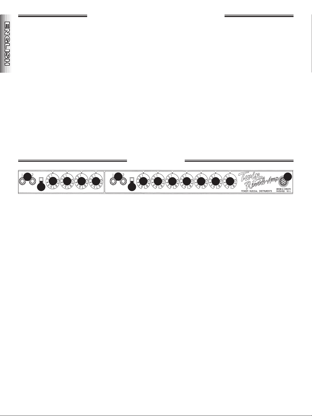
Fender® `65 Twin Reverb®
VOLUME TREBLE MIDDLE BASS VOLUME TREBLE MIDDLE BASS REVERB SPEED INTENSITY
BRIGHTBRIGHT
VIBRATO
NORMAL
B
C
E
F
G
H
I
J
K
L
M
N
O
P
A
D
Front Panel
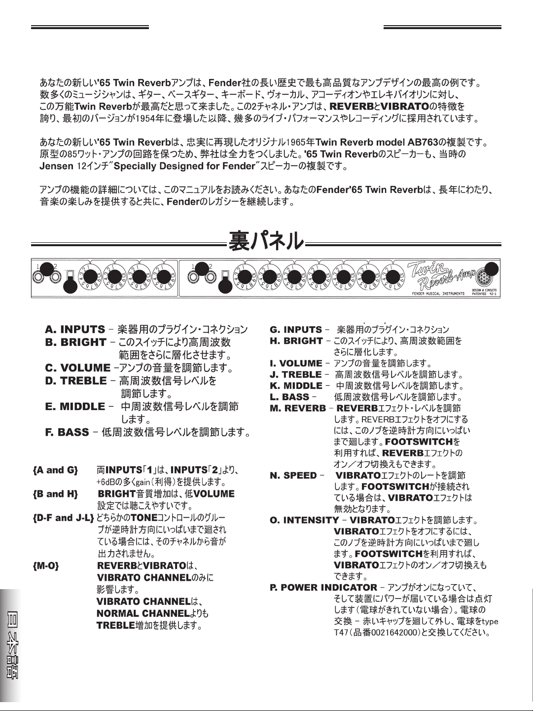
Your "new" '65 Twin Reverb® amplifier is living proof of
the quality and longevity of Fender® amplifier designs.
Over the years, many musicians have found the versatile
Twin Reverb a perfect match for guitar, bass guitar,
keyboards, vocals, accordion, and the electric violin
among others. Featuring REVERB and VIBRATO, this
two-channel amplifier has been used on thousands of
recordings and countless live performances since 1954
when the first version appeared on the music scene.
Your new '65 Twin Reverb is a faithful reproduction of
an original 1965 Twin Reverb model AB 763. Every
effort has been made to keep the circuitry exactly like
the original. For improved reliability and manufacturing
efficiency, a printed circuit board for the components is
used in place of the original phenolic parts panel. The
power and output transformers used in the 85-watt
'65 Twin Reverb are built to the original specifications
and although some components used in this re-issue
amplifier are different in size and shape from the earlier
version, the component values are identical. The
speakers in the '65 Twin Reverb are duplicates of the
original Jensen 12-inch "Specially Designed for Fender"
speakers used for many years during the 1960s.
It is suggested you read this manual thoroughly to
understand all the features and functions of the
amplifier. The purchase of a Fender amplifier will
provide years of musical enjoyment and the '65 Twin
Reverb helps keep the Fender legacy going strong.
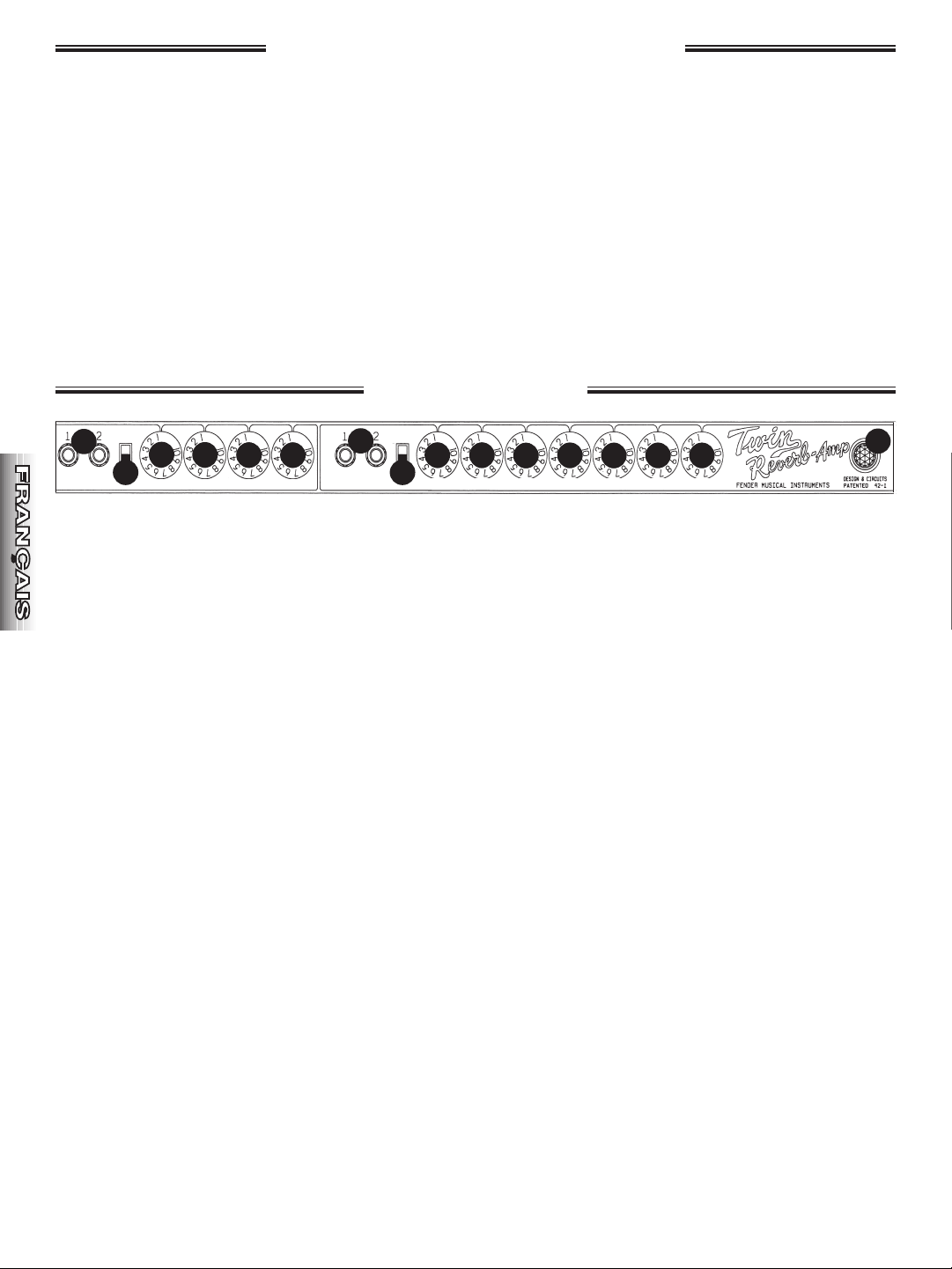
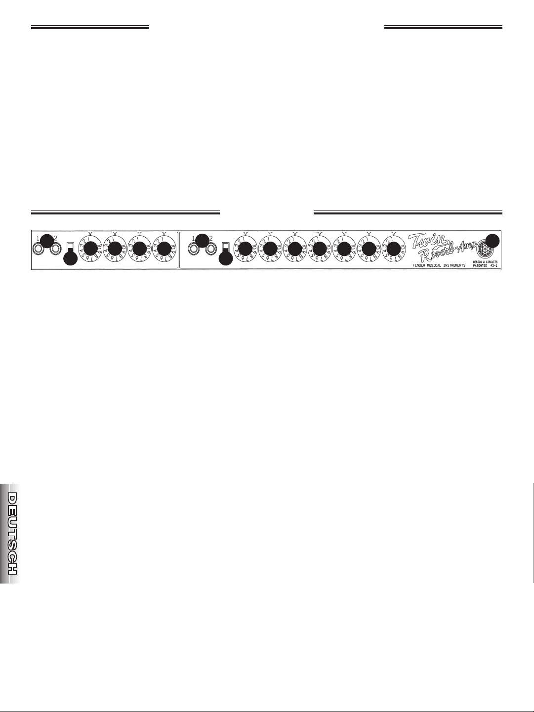
NORMAL CHANNEL (A-F)
A. INPUTS - Plug-in connections for instruments.
B. BRIGHT - This switch provides an extra boost to
the high-frequency range.
C. VOLUME - Adjusts the loudness of the amplifier.
D. TREBLE - Adjusts the high-frequency tone.
E. MIDDLE - Adjusts the mid-frequency tone.
F. BASS - Adjusts the low-frequency tone.
NOTES
• {AandG}BothINPUTS"1"provide+6dBgainmore
thanINPUTS"2."
• {BandH}TheBRIGHTtoneboosttapersoffasthe
VOLUMEsettingincreases.
• {D-F and J-L} If either group of tone controls is
turned fully counter-clockwise there will be no
sound from that channel.
• {M-O}REVERBandVIBRATOaffectonlytheVIBRATO
CHANNEL.
• TheVIBRATOchannelprovidesmorehigh-frequen-
cyresponsethantheNORMALchannel.
VIBRATO CHANNEL (G-O)
G. INPUTS - Plug-in connections for instruments.
H. BRIGHT - This switch provides an extra boost to the
high-frequency range.
I. VOLUME - Adjusts the loudness of the amplifier.
J. TREBLE - Adjusts the high-frequency tone.
K. MIDDLE - Adjusts the mid-frequency tone.
L. BASS - Adjusts the low-frequency tone.
M. REVERB - Adjusts the REVERB effect level. Switch OFF
the REVERB effect by turning this knob fully counter-
clockwise. The FOOTSWITCH can also be used to
switchON/OFFtheREVERBeffect.
N SPEED - Adjusts the rate of the VIBRATO effect. The
footswitch must be connected and switched on for
the Vibrato effect to function.
O. INTENSITY - Adjusts the intensity of the VIBRATO
effect. The footswitch must be connected and
switched on for the Vibrato effect to function.
P. POWER INDICATOR - Illuminates when the amplifier
isONandreceivingpower.Unscrewtheredjeweled
cover for bulb (type T47) replacement.
7
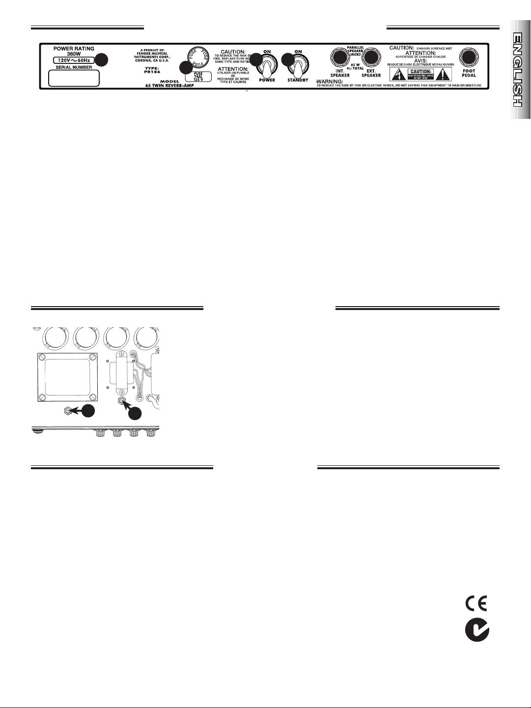
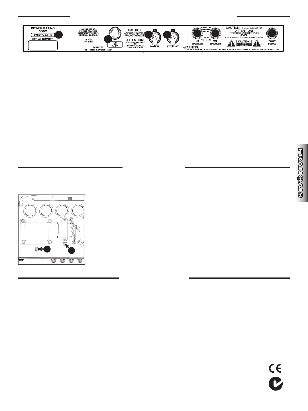
A. POWER CORD - Connect the power cord to a grounded AC
receptacle in accordance with the voltage and frequency
ratings shown on the rear panel of your amplifier.
B. FUSE - Protects the amplifier from electrical faults. Replace
a blown fuse only with same type and rating as listed on
the fuse holder. If the amplifier repeatedly blows fuses,
take the amplifier to an authorized Fender Service Center.
C. POWER - Switches the amp ON and OFF and completely
disconnects the apparatus from the mains.
D. STANDBY-UseSTANDBYinsteadofswitchingPOWERoff
for short breaks to eliminate the tube warm-up delay upon
returning to play. This will also extend tube life span.
E. MAIN SPEAKER - Plug-in connection for speakers. A
4-ohm minimum speaker must always be connected at this
jack when the amplifier is ON to prevent damage to the
amplifier.
F. EXTERNAL SPEAKER - Plug-in connection for an external
speaker. This jack is wired in parallel with the MAIN
SPEAKER JACK {E}. A total speaker impedance load of
4-ohms should be used to avoid damage to the
amplifier.
G. FOOTSWITCH - Plug-in connection for the FOOTSWITCH
which enables ON/OFF switching of the VIBRATO and
REVERB effects.
The footswitch must be connected
and switched on for the Vibrato effect to function.
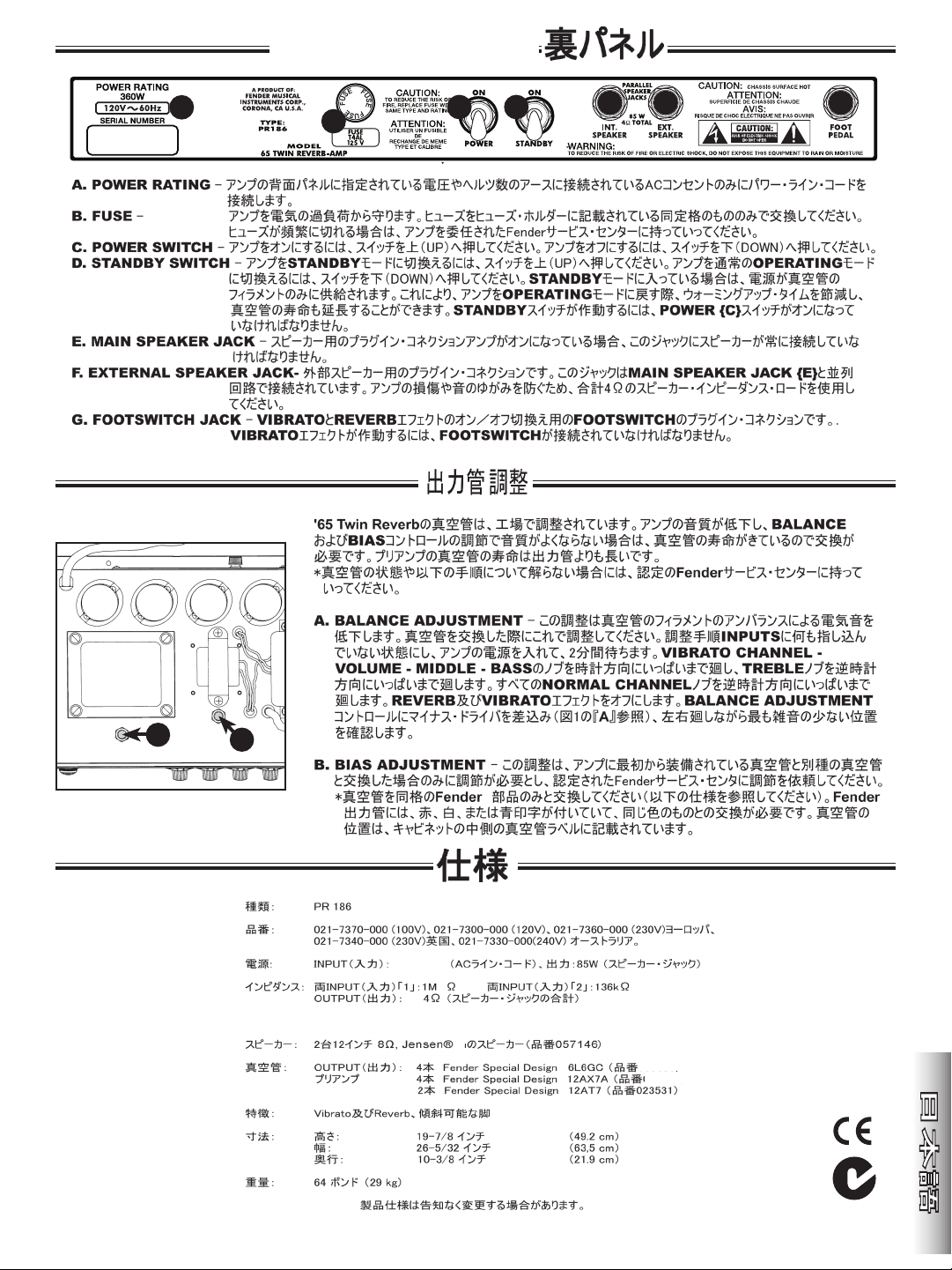
TYPE: PR 186
PART NUMBER: 021-7300-000 (120V, 60Hz) USA, 021-7360-000 (230V, 50Hz) Euro, 021-7340-000 (230V, 50Hz) UK
021-7370-000 (100V, 50/60Hz) Japan, , 021-7330-000 (240V, 50Hz) Australia.
POWER REQUIREMENTS: 360 watts
POWER OUTPUT: 85 watts R.M.S.
IMPEDANCES: INPUTS 1: 1M ohm (both channels), INPUTS 2: 136k ohms (both channels)
OUTPUT: 4 ohms (both speaker jacks together)
SPEAKER COMPLEMENT: Two 12 in, 8 ohm Jensen
®
(P/N-057146)
TUBE COMPLEMENT: OUTPUT: Four Fender Special Design 6L6GC’s (P/N-039214),
PRE-AMP: Four Fender Special Design 12AX7A’s (P/N-013341),
Two Fender Special Design 12AT7’s (P/N-023531)
DIMENSIONS: HEIGHT: 19-7/8 in (49.2 cm)
WIDTH: 26-5/32 in (63.5 cm)
DEPTH: 10-3/8 in (21.9 cm)
WEIGHT: 64 lb (29 kg)
Product specifications are subject to change without notice.
`65 Twin Reverb – Rear Panel
If the sound quality of the amp has degraded noticeably the tubes may be worn and need replacement. Output tube typically need
replacement before pre-amp tubes. If you are not sure about the condition of your tubes or the following procedures, take your amplifier to
an authorized Fender Service Center. Replace tubes with identical Fender® original equipment only (see SPECIFICATIONS below). Tube location is printed on the
tube label, inside the cabinet.
A. HUM BALANCE ADJUSTMENT - This adjustment minimizes the hum heard at the speakers due to tube filament imbalance.
•AdjustmentInstructions:TurntheamplifierONfor2minuteswithnothingpluggedintoanyoftheINPUTS.RotatetheVIBRATO
CHANNEL volume, middle, and bass knobs fully clockwise and the treble knob fully counter-clockwise. Rotate ALL of the
NORMALCHANNELknobsfullycounter-clockwise.SwitchOFFtheREVERBandVIBRATOeffects.Insertaslottedscrewdriverintothe
BALANCEADJUSTMENTcontrol,(see“A”inFIG.1)androtatebackandforthtothepositionwiththeleastamountofhum.
B. BIAS ADJUSTMENT -ThisadjustmentshouldbemadeonlybyanauthorizedFenderServiceCenter.BIASneedsadjustmentonly
if the replacement output tubes are not identical to the original tubes.
CHASSIS
BOTTOM
VIEW
A
B
Tube Adjustments
Specifications
FIG. 1
B
E
F
A
C D
G
8
Fender® `65 Twin Reverb®
VOLUME TREBLE MIDDLE BASS VOLUME TREBLE MIDDLE BASS REVERB SPEED INTENSITY
BRIGHTBRIGHT
VIBRATO
NORMAL
B
C
E
F
G
H
I
J
K
L
M
N
O
P
A
D
Panel Frontal
El "nuevo" amplificador '65 Twin Reverb es unaprueba
de la calidad y la longevidad que caracterizaa los
diseños de amplificadores Fender. Sonmuchos los
músicos que han encontrado en elversátil Twin Reverb
la herramienta perfecta paraguitarras, bajos, teclados,
vocales, acordeones yviolines eléctricos. Este
amplificador de doscanales, dotado con las funciones
REVERB yVIBRATO, se ha utilizado en miles de
grabaciones yactuaciones en directo desde 1954, año
en queapareció la primera versión.
El nuevo '65 Twin Reverb es una fiel reproduccióndel
modelo original de 1965 Twin Reverb modelAB763. Se
ha hecho todo lo posible para que loscircuitos sean
exactamente iguales a los delamplificador de 85 vatios
original. Los altavocesdel amplificador '65 Twin Reverb
son replicas de losaltavoces originales Jensen de 12
pulgadasdiseñados especialmente para Fender
"SpeciallyDesigned for Fender".
Consulte este manual para una mejor comprensiónde
las funciones del amplificador. El amplificadorFender
'65 Twin Reverb le permitirá disfrutar de lamúsica
durante años y mantener vivo el legadoFender.
CANAL NORMAL (A-F)
A. INPUTS - Conexiones de entrada para enchufar
instrumentos.
B. BRIGHT - Este conmutador permite aumentar
aun mas la gama de frecuencias altas.
C. VOLUME - Ajusta el volumen del amplificador.
D. TREBLE - Ajusta tono de frecuencia alta.
E. MIDDLE - Ajusta tono de frecuencia media.
F. BASS - Ajusta el tono de frecuencia baja.
NOTAS:
{AandG}Lasentradas"1"INPUTSproporcionanuna
ganancia de +6dB m s que las entradas "2"
INPUTS.
{B and H} Se puede apreciar mejor el aumento de
tonoBRIGHTanivelesdeVOLUMEmsbajos.
{D-F and J-L} Si se gira completamente hacia la
izquierda cualquiera de los grupos de controles
de tonoTONE, el CHANNEL dejar de transmitir
sonido.
{M-O} REVERB y VIBRATO solo afectan al canal de
vibratoVIBRATOCHANNEL.
El canal de vibrato VIBRATO CHANNEL permite
aumentar los agudos TREBLE en mayor medida
queelcanalnormalNORMALCHANNEL.
VIBRATO CHANNEL (G-O)
G. INPUTS - Conexiones de entrada para enchufar
instrumentos.
H. BRIGHT - Este conmutador permite aumentar aun mas
la gama de frecuencias altas.
I. VOLUME - Ajusta el volumen del amplificador.
J. TREBLE - Ajusta tono de frecuencia alta.
K. MIDDLE - Ajusta el tono de frecuencia media.
L. BASS - Ajusta el tono de frecuencia baja.
M. REVERB - Ajusta el nivel del efecto REVERB. Para
desactivar el efecto REVERB, gire este boton
completamente hacia la izquierda. Tambien se puede
utilizar el conmutador de pedal FOOTSWITCH para
desactivar el efecto REVERB.
N. SPEED - Ajusta la velocidad del efecto VIBRATO. El
efecto VIBRATO no funcionar si el conmutador de
pedalFOOTSWITCHnoestconectado.
O. INTENSITY - Ajusta la intensidad del efecto VIBRATO.
Para desactivar el efecto VIBRATO, gire este boton
completamente hacia la izquierda. Tambien se puede
utilizar el conmutador de pedal FOOTSWITCH para
desactivar el efecto VIBRATO.
P. POWER INDICATOR - Se ilumina cuando el amplificador
est activado y recibe alimentacion (siempre que la
bombilla no est fundida). Sustitucion de la bombilla -
Desenrosque el foco rojo y sustituya la bombilla por
otra del "tipo T47" (Pieza-0021642000).
9
A. POWER RATING - Conecte el cable de alimentacion a una
toma de CA de acuerdo con las especificaciones de voltaje y
frecuencia indicadas en el panel posterior del amplificador.
B. FUSE FUSIBLE - Protege el amplificador de fallos electricos.
Para sustituir los fusibles, debe utilizar el mismo tipo y la
misma potencia indicados en el portafusible. En caso de que
los fusibles se fundan con frecuencia, lleve el amplificador a
un centro de servicio Fender autorizado.
C. POWER-PulsehaciaARRIBAparaENCENDERelamplificador.
PulsehaciaABAJOparaAPAGARelamplificador.
D. STANDBY - Pulse ABAJO hacia para poner el amplificador en
elmododeesperaSTANDBY.EnelmododeesperaSTANDBY,
solo se suministra potencia a los filamentos de los tubos. De
este modo, se evitan sobrecalentamientos cuando el
amplificadorvuelvealmododefuncionamientoOPERATING
y se prolonga la duracion de los tubos.
E. MAIN SPEAKER - Conexion de enchufe para altavoces. Deber
haber siempre un altavoz conectado a este conector cuando
el amplificador est encendido.
F. EXTERNAL SPEAKER - Conexion de enchufe para un altavoz
externo. Este conector se conecta en paralelo al conector del
altavozprincipalMAINSPEAKERJACK{E}.Sedebeutilizaruna
carga de mpedancia de altavoz total de 4 ohmios para que no
se produzcan distorsiones ni se dane el amplificador.
G. FOOTSWITCH - Conexion de enchufe para el conmutador de
pedal FOOTSWITCH que permite activar o desactivar los
efectos VIBRATO y REVERB. El efecto VIBRATO no funcionar si
elconmutadordepedalFOOTSWITCHnoestconectado.
TIPO: PR 186
NÚMEROS DE PIEZA: 021-7370-000 (100V) Japan, 021-7300-000 (120V) USA, 021-7360-000 (230V) Europa,
021-7340-000 (230V) RU, 021-7330-000 (240V) Australia.
POTENCIA: ENTRADA: 360 vatios (cable de línea de CA), SALIDA: 85 vatios (conectores de altavoces)
IMPEDANCIAS: Ambas ENTRADAS "1": 1 M ohmio, Ambas ENTRADAS "2": 136 k ohmios
SALIDA: 4 ohmios (combinación de conectores de altavoces)
COMPLEMENTO DE ALTAVOZ: Dos altavoces de 12 pulgadas, 8 ohmio, Jensen
®
(pieza-057146)
TUBOS: SALIDA: Cuatro 6L6GC de diseño especial Fender Fender Special Design 6L6GC (Pieza-039214),
PREAMPLIFICADOR: Cuatro 12AX7A de diseño especial Fender Fender Special Design 12AX7A
(Pieza-013341),
Dos 12AT7 de diseño especial Fender Fender Special Design 12AT7 (Pieza-023531)
FUNCIONES: Vibrato y Reverb, patillas inclinables.
DIMENSIONES: ALTO: 19-7/8 pulgadas (49,2 cm)
ANCHO: 26-5/32 pulgadas (63,5 cm)
FONDO: 10-3/8 pulgadas (21,9 cm)
PESO: 64 lb. (29 kg)
Las especificaciones del producto están sujetas a cambios sin previo aviso.
`65 Twin Reverb – Panel Posterior
Si el amplificador ha perdido calidad de sonido es un indicio de que los tubos están desgastados y, por lo tanto, necesitan ser sustituidos. Los tubos del preamplificador suelen
durar más que los tubos de salida. Si desconoce la condición de los tubos o no entiende los procedimientos siguientes, lleve el amplificador a un centro de servicio Fender
autorizado.
A. HUM BALANCE ADJUSTMENT - Este ajuste reduce el zumbido que producen los altavoces debido al desequilibrio de los
filamentos de los tubos. Realice el ajuste una vez sustituidos los tubos. Instrucciones para el ajuste - Mantenga encendido el
amplificador durante 2 minutos sin ningún dispositivo conectado a las entradas INPUTS. Gire los botones de volumen VOLUME,
mediosMIDDLEygravesBASSdelcanaldevibratoVIBRATOCHANNELcompletamentehacialaderechayeldeagudosTREBLE
completamente hacia la izquierda. Gire TODOS los botones del canal normal NORMAL CHANNEL completamente hacia la
izquierda.DesconectelosefectosREVERByVIBRATO.Acontinuación,introduzcaundestornilladorranuradoenelcontroldel
ajustedebalanceBALANCEADJUSTMENT(véase"A"enFIG1)ygíreloatrásyadelantehastaalcanzarlaposiciónenlaquese
reduzca al máximo el zumbido.
B. BIAS ADJUSTMENT - Este ajuste sólo se debe realizar cuando los tubos de salida hayan sido sustituidos por unos distintos a
los originales y únicamente en un centro de servicio Fender autorizado. La ubicación del tubo aparece impresa en la etiqueta
del tubo, en el interior de la caja.
CHASSIS
BOTTOM
VIEW
A
B
Tubo Ajustes
Especificaciones
FIG. 1
B
E
F
A
C D
G
10
Fender® `65 Twin Reverb®
VOLUME TREBLE MIDDLE BASS VOLUME TREBLE MIDDLE BASS REVERB SPEED INTENSITY
BRIGHTBRIGHT
VIBRATO
NORMAL
B
C
E
F
G
H
I
J
K
L
M
N
O
P
A
D
Panneau Avant
Votre nouvel amplifcateur '65 Twin Reverb est lapreuve
de la qualité et de la longévité du conceptdes
amplificateurs Fender. Selon de nombreuxmusiciens, le
Twin Reverb, dotés de multiplesfonctions, est parfait
pour les guitares, les guitaresbass, les claviers, les voix,
lesaccordéonsetlesviolonsélectriques.GrâceàREVERB
etVIBRATO,cetamplificateuràdeuxcanauxaétéutilisé
lors demilliers d'enregistrements et
d'innombrablesconcerts en direct depuis 1954, année
de lapremière version.
Votre nouveau '65 Twin Reverb est une reproductionfidèle
du Twin Reverb model AB763 de 1965. Tousles efforts
nécessaires ont été conçus afin depréserver l'aspect
original des circuits tels qu'ilsexistaient sur l'amplificateur
85 watt. Les hautparleursdu '65 Twin Reverb sont les
répliques deshaut-parleurs Jensen 12 pouces originaux
«Specially Designed for Fender ».
Veuillez lire ce manuel pour bien comprendre toutesles
fonctions de l'amplificateur. Votre Fender '65Twin
Reverb vous réjouira tout au long de votrecarrière
musicale et prouvera ainsi qu'il est le dignehéritier de la
lignée Fender !
CANAL NORMAL (A-F)
A. INPUTS-Uneprisedeconnexion
pourinstruments.
B. BRIGHT - Cet interrupteur amplifie davantagela
gamme des hautes fréquences.
C. VOLUME - Permet de régler le son
del'amplificateur.
D. TREBLE - Permet de régler le niveau dusignal de
haute fréquence.
E. MIDDLE - Permet de régler le niveau dusignal de
moyenne fréquence.
F. BASS - Permet de régler le niveau du signalde
basse fréquence.
REMARQUES:
{AetG}LesdeuxentréesINPUTS"1«fournissent
+6dBdeplusquelesentréesINPUTS»2".
{BetH}lessonsclairsBRIGHTsontplusperceptibles
lorsqueleVOLUMEestfaible.
{D-FetJ-L}Sivousaveztournétouslesgroupesde
boutonssonsTONEjusqu'enbutéedanslesens
inverse des aiguilles d'une montre, cecanal
CHANNELn'émetaucunson.
{M-O}REVERBetVIBRATOnefonctionnentqu'avec
VIBRATOCHANNEL.LeVIBRATOCHANNEL
amplifie davantageles aiguës TREBLE que le
canalnormalNORMALCHANNEL.
VIBRATOCHANNEL(G-O)
G. INPUTS-Uneprisedeconnexionpourinstruments.
H. BRIGHT - Cet interrupteur amplifie davantage
lagamme des hautes fréquences.
I. VOLUME - Permet de régler le son del'amplificateur.
J. TREBLE - Permet d'ajuster le niveau du signal dehaute
fréquence.
K. MIDDLE - Permet de régler le niveau du signal
demoyenne fréquence.
L. BASS - Permet de régler le niveau du signal debasse
fréquence.
M. REVERB - Permet d'ajuster le niveau de l'effetREVERB.
LaFOOTSWITCH(pédale)permetégalementd'arrêter/
de mettre en marche l'effetREVERB.
N. SPEED - Permet d'ajuster le taux d'effet VIBRATO.L'effet
VIBRATOnefonctionnepassileFOOTSWITCHn'estpas
branché.
O. INTENSITY - Permet d'ajuster l'intensité de
l'effetVIBRATO.Vouspouvezarrêterl'effetVIBRATO
entournant ce bouton jusqu'en butée dans le
sensinverse des aiguilles d'une montre.
LaFOOTSWITCH(pédale)permetégalementd'arrêter/
de mettre en marche l'effet VIBRATO.
P. POWER INDICATOR - S'allume lorsquel'amplificateur
est branché et qu'il est en marche(sauf si l'ampoule ne
fonctionne plus). Ampoule derechange: Dévissez le
cache rouge et remplacezl'ampoule: type T47" (Part-
0021642000).
11
A. POWER CÂBLE -ConnectezlecâbleàunepriseCAmiseà
la terre selon le voltage et la fréquence indiquéssur le
panneau arrière de l'appareil.
B. FUSE - Ce fusible protège l'amplificateur des
incidentsélectriques. Remplacez le fusible uniquement par
desfusibles de type et de caractéristiques identiques,comme
mentionné sur le porte-fusible. Si les fusiblesde
l'amplificateur sautent de manière répétée, amenezle chez
un réparateur Fender agréé.
C. POWER-Mettezenpositionhautepourmettrel'amplificateur
sous tension.
D. STANDBY - Mettez en position haute pour
mettrel'amplificateur en mode STANDBY. Enfoncez
pourmettre l'amplificateur en mode normal OPERATING.
EnmodeSTANDBY,seulslesfilamentsdestubessontsous
tension. Ceci élimine le temps de chauffe
lorsquel'amplificateur est remis en mode normal
OPERATINGet prolonge la durée de vie des tubes. Le
boutonPOWER {C} doit être allumé pour que
l'interrupteurSTANDBYpuissefonctionner.
E. MAIN SPEAKER - Une prise de connexion pour les
hautparleurs.Un haut parleur doit toujoursêtre connecté
àcettepriselorsquel'amplificateurestenmarche.
F. EXTERNAL SPEAKER-Uneprisedeconnexionpourhaut-
parleur externe. Cette prise est montée enparallèle avec la
prise MAIN SPEAKER JACK {E}.Utilisez une charge totale
d'impédance du haut-parleurde 4 Ohms pour éviter une
distorsion et ne pasendommager l'amplificateur.
G. FOOTSWITCH - Une prise de connexion pour lapédale
FOOTSWITCH qui permet l'arrêt ou la mise enmarche de
l'effet VIBRATO et de l'effet REVERB.L'effet VIBRATO ne
fonctionnepassileFOOTSWITCHn'estpasbranché.
TYPE: PR 186
NUMEROS DE PIECE: 021-7370-000(100V)Japan, 021-7300-000 (120V) USA, 021-7360-000 (230V) Europe,
021-7340-000 (230V) UK, 021-7330-000 (240V) Australie.
PUISSANCE: ENTREE: 360 watt (câble CA), SORTIE: 85 watt (prises des haut-parleurs)
IMPEDANCE: Les deux ENTREES "1«:1Mohm,LesdeuxENTREES »2":136kohms
SORTIE: 4ohms(prisesdeshaut-parleurscombinées)
HAUT-PARLEURS INTEGRES: deuxhaut-parleursd'époqueJensen
®
de 12 pouces, 8 ohms, (pièce 057146).
TUBES: SORTIE: Quatre Fender Special Design 6L6GC (pièce 039214),
PREAMPLIFICATEUR: Quatre Fender Special Design 12AX7A (pièce 013341),
Deux Fender Special Design 12AT7 (pièce 023531),
CARACTERISTIQUES: VibratoetReverb,supportréglableversl'arrière
DIMENSIONS: HAUTEUR: 19-7/8 in. (49,2 cm)
LARGEUR: 26-5/32 in. (63,5 cm)
PROFONDEUR: 10-3/8 in. (21,9 cm)
POIDS: 64 lb. (29 kg)
Lesspécificationsdeproduitspeuventchangersanspréavis.
`65 Twin Reverb – Panneau Arrière
Silaqualitédusonlaisseàdésirercelasignifiequelestubessontusésetqu'ilsdoiventêtreremplacés.Laduréedeviedestubesdupréamplificateurestpluslonguequecelledestubesde
sortie.*Sivousn'êtespassûrdel'étatdestubesousivouspenseznepascomprendrelaprocéduresuivante,emmenezvotreamplificateurchezunréparateurFenderagréé.
A. HUM BALANCE ADJUSTMENT -Ceréglagepermetdediminuerlesbourdonnementsdusàundéfautdebalancedesfilamentsdestubes.Il
doitêtreeffectuéàchaquefoisquelestubessonremplacés.Instructionsderéglage:Mettezl'amplificateurenmarchepourdeuxminutessans
qu'iln'yestd'accessoirebranchésurlesentréesINPUTS.TournezlesboutonsVOLUME,MIDDLE,etBASSduVIBRATOCHANNELjusqu'enbutée
danslesensdesaiguillesd'unemontreetleboutonTREBLEjusqu'enbutéedanslesensinversedesaiguillesd'unemontre.Tourneztousles
boutonsducanalnormalNORMALCHANNELjusqu'enbutéedanslesensinversedesaiguillesd'unemontre.Mettezenmarchel'effetREVERB
etleVIBRATO.InsérezensuiteuntournevisplatdanslacommandeBALANCEADJUSTMENT,(voir"A"danslafig.1)etréglezdetellemanièreà
ce que vous entendiez le moins possible le bourdonnement.
B. BIAS ADJUSTMENT -Ceréglagedoitêtreeffectuéuniquementsilestubesdesortiesontremplacéspardestubesnecorrespondantpasà
l'originaletseulementparunréparateurFenderagréé.RemplacezlestubesuniquementpardestubesFender®originauxidentiques(voirles
SPECIFICATIONSci-dessous).Lesemplacementsdestubessontmentionnéssurlaplaquesignalétiqueàl'intérieurduchâssis.
Tube Reglages
Caractéristiques
CHASSIS
BOTTOM
VIEW
A
B
FIG. 1
B
E
F
A
C D
G
12
Fender® `65 Twin Reverb®
VOLUME TREBLE MIDDLE BASS VOLUME TREBLE MIDDLE BASS REVERB SPEED INTENSITY
BRIGHTBRIGHT
VIBRATO
NORMAL
B
C
E
F
G
H
I
J
K
L
M
N
O
P
A
D
Pannello Frontale
Il "nuovo" amplificatore '65 Twin Reverb la prova della
qualit e della longevit della progettazione degli
amplificatori Fender. Molti vocalist e musicisti hanno
trovato il versatile Twin Reverb perfetto per la chitarra, il
basso, le tastiere, la fisarmonica e il violino elettrico.
Con le funzioni REVERB e VIBRATO, questo amplificatore
a due canali stato usato su migliaia di registrazioni e
infinite performance live dal 1954, anno in cui comparve
la prima versione.
Il nuovo '65 Twin Reverb una fedele riproduzione di un
Twin Reverb model AB763 originale del 1965. stato
fatto di tutto per mantenere i circuiti esattamente
uguali a quelli dell'amplificatore originale da 85 watt.
Gli speaker del '65 Twin Reverb sono la copia degli
speaker originali Jensen da 12 pollici "Specially Designed
for Fender"
Leggere il manuale per la descrizione di tutte le funzioni
dell'amplificatore. Il Fender '65 Twin Reverb dar anni di
soddisfazioni musicali e terr alto il nome della Fender.
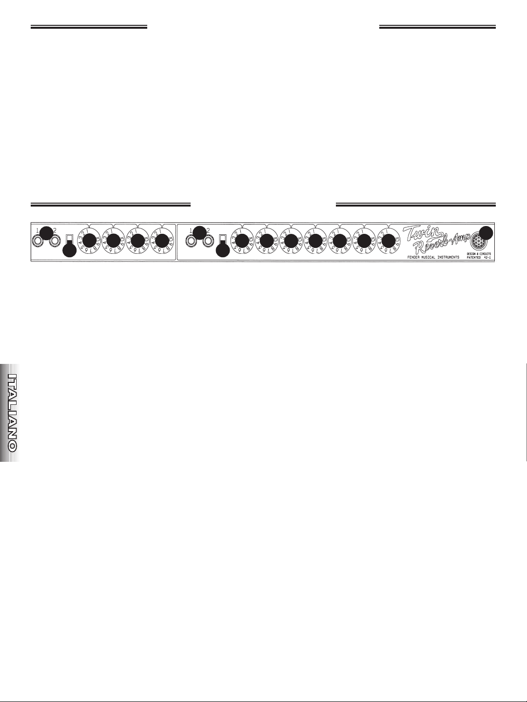
CANALE NORMALE (A-F)
A. INPUTS - Connessioni a spina degli strumenti.
B. BRIGHT - Questo commutatore d un aumento
ulteriore all'intervallo di alte frequenze.
C. VOLUME - Regola il volume dell'amplificatore.
D. TREBLE - Regola il livello del segnale di alta
frequenza.
E. MIDDLE - Regola il livello del segnale di media
frequenza.
F. BASS - Regola il livello del segnale di bassa
frequenza.
NOTE:
{AeG}IdueINPUT"1"forniscono+6dBdiguadagno
pidegliINPUT"2"
{BeH}IlboostditonoBRIGHTsirilevamaggiormente
alleimpostazionipibassediVOLUME.
{D-FeJ-L}SeunodeigruppidicontrolliTONEviene
ruotato completamente in senso antiorario, non
verremessoalcunsuonodaquelCHANNEL.
{M-O}REVERBeVIBRATOinfluisconosolosuVIBRATO
CHANNEL.
VIBRATOCHANNELforniscepiTREBLEdiNORMAL
CHANNEL.
CANALE VIBRATO (G-O)
G. INPUTS - Connessioni a spina degli strumenti.
H. BRIGHT - Questo commutatore d un aumento ulteriore
all'intervallo di alte frequenze.
I. VOLUME - Regola il volume dell'amplificatore.
J. TREBLE - Regola il livello del segnale di alta frequenza.
K. MIDDLE - Regola il livello del segnale di media
frequenza.
L. BASS - Regola il livello del segnale di bassa frequenza.
M. REVERB - Regola il livello dell'effetto REVERB. Disattivare
l'effetto REVERB ruotando la manopola completamente
in senso antiorario. Per attivare/disattivare l'effetto
REVERBanchepossibileusareilFOOTSWITCH.
N. SPEED - Regola la frequenza dell'effetto VIBRATO.
L'effettoVIBRATOnonfunzionaseilFOOTSWITCHnon
inserito.
O. INTENSITY - Regola l'intensit dell'effetto VIBRATO.
Disattivare l'effetto VIBRATO ruotando la manopola
completamente in senso antiorario. Per attivare/
disattivare l'effetto VIBRATO anche possibile usare il
FOOTSWITCH.
P. POWER INDICATOR (spia di alimentazione) - accesa
quando l'amplificatore acceso e alimentato, a meno
che la lampadina non sia fulminata. Sostituzione della
lampadina: Svitare il coperchio rosso e sostituire la
lampadina(tipoT47,N.parte0021642000).
13
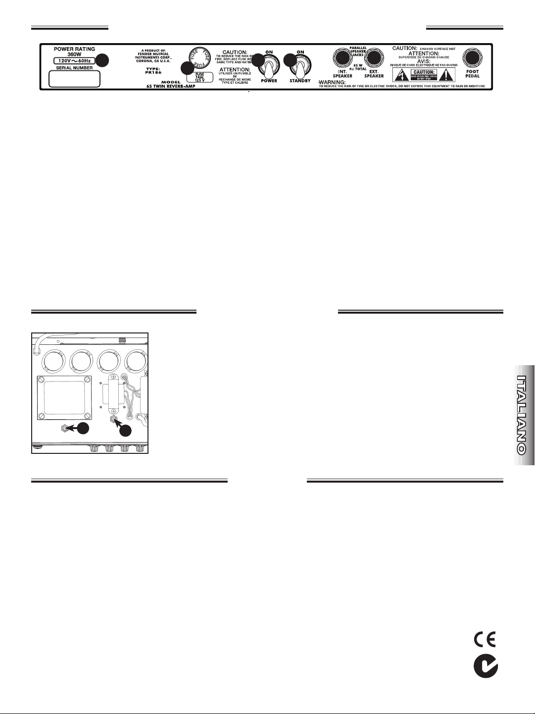
A. POWER RATING - Collegare il cavo di alimentazione a una
presa c.a. con messa a terra conforme ai requisiti di
tensione e frequenza indicati sul pannello posteriore
dell'unit .
B. FUSE (Fusibile) - Protegge l'amplificatore dagli sbalzi di
tensione. Sostituire il fusibile solo con un fusibile dello
stesso tipo e della stessa potenza (come indicato sul
portafusibile). Se i fusibili dell'amplificatore si fulminano
ripetutamente, portare l'amplificatore presso un Centro di
assistenza Fender autorizzato.
C. POWER (Alimentazione) - Premere verso l'alto per
accendere l'alimentazione. Premere verso il basso per
spegnere l'alimentazione.
D. STANDBY (Attesa) - Premere verso l'alto per mettere
l'amplificatoreinmodalitSTANDBY.Premereversoilbasso
per mettere l'amplificatore in normale modalit di
funzionamentoOPERATING.InmodalitSTANDBY,vengono
alimentati solo i filamenti delle valvole. In questo modo si
elimina il tempo di riscaldamento quando si riporta
l'amplificatore in modalit OPERATING e si aumenta la
duratadellevalvole.L'interruttorePOWER{C.}deveessere
suONperchl'interruttoreSTANDBYfunzioni.
E. MAIN SPEAKER - Connessione a spina degli speaker.
Quando l'amplificatore acceso, uno speaker 4Ω deve
essere sempre collegato a questo jack.
F. EXTERNAL SPEAKER - Connessione a spina per uno
speaker esterno. Questo jack collegato in parallelo al
MAIN SPEAKER JACK {E}. Per evitare distorsione o danni
all'amplificatore, si dovrebbe usare un carico di impedenza
totale dello speaker di 4 Ohm.
G. FOOTSWITCH - Connessione a spina per il FOOTSWITCH
che consente di eseguire la commutazione degli effetti
VIBRATO e REVERB. L'effetto VIBRATO non funziona se il
FOOTSWITCHnoninserito.
TIPO: PR 186
NUMERI DI PARTE: 021-7370-000 (100V) Japan, 021-7300-000 (120V) USA, 021-7360-000 (230V) Europa,
021-7340-000 (230V) UK, 021-7330-000 (240V) Australia.
POTENZA: INPUT: 360 watt (cavo di alimentazione c.a.), OUTPUT: 85 watt (jack degli speaker)
IMPEDENZE: Entrambi gli INPUT "1":1Mohm,EntrambigliINPUT "2":136kohm
OUTPUT: 4 ohm (jack degli speaker combinati)
COMPLEMENTO SPEAKER: Due speaker da 12 pollici, 8 ohm, speaker d'epoca Jensen® (N.-parte 057146)
VALVOLE: OUTPUT: Quattro Fender Special Design 6L6GC (N.-parte 039214),
PREAMPLIFICATORE: Quattro Fender Special Design 12AX7A (N.-parte 013341),
Due Fender Special Design 12AT7 (N.-parte 023531)
CARATTERISTICHE: Vibrato e Reverb, supporti per inclinazione.
DIMENSIONI: ALTEZZA: 49,2 cm (19-7/8 pollici)
LARGHEZZA: 63,5 cm (26-5/32 pollici)
PROFONDITÀ: 21,9 cm (10-3/8 pollici)
PESO: 29 kg (64 libbre)
Le specifiche dei prodotti sono soggette a modifica senza preavviso.
`65 Twin Reverb – Pannello Posteriore
Selaqualitàdelsuonodell'amplificatoreèdiminuitalevalvolesonoesausteeoccorresostituirle.Levalvoledelpreamplificatorehannouna
durata minore delle valvole di output.* Per domande sulle condizioni delle valvole o sulle procedure descritte di seguito, portare l'amplificatore
presso un Centro di assistenza Fender autorizzato.
A. HUM BALANCE ADJUSTMENT - Questa regolazione riduce al minimo il rumore degli speaker dovuto a mancato balance dei filamenti delle
valvole.Regolaredopolasostituzionedellevalvole.Istruzioniperlaregolazione:Accenderel'amplificatoreper2minutisenzacollegare
componentianessunodegliINPUT.RuotarelemanopoleVIBRATOCHANNEL-VOLUME,MIDDLEeBASScompletamenteinsensoorarioe
la manopola TREBLE completamente in senso antiorario. RuotareTUTTE le manopole NORMAL CHANNEL completamente in senso
antiorario.DisattivareglieffettiREVERBeVIBRATO.InserireuncacciavitepiattonelcontrolloBALANCEADJUSTMENT(vedere"A"nellaFIG.
1)eruotarloavantieindietroportandolonellaposizioneincuisisentelaquantitàminoredironzio.
B. BIAS ADJUSTMENT - Questa regolazione va eseguita solo se le valvole di output vengono sostituite con valvole non originali e deve essere
svolta solo presso un Centro assistenza Fender autorizzato. Sostituire le valvole solo con parti di ricambio originali Fender® (vedere le
specifiche di seguito). La posizione delle valvole è stampata sull'etichetta della valvola, all'interno della cassa.
CHASSIS
BOTTOM
VIEW
A
B
Valvola regolazione
Specifiche
FIG. 1
B
E
F
A
C D
G
14
Fender® `65 Twin Reverb®
VOLUME TREBLE MIDDLE BASS VOLUME TREBLE MIDDLE BASS REVERB SPEED INTENSITY
BRIGHTBRIGHT
VIBRATO
NORMAL
B
C
E
F
G
H
I
J
K
L
M
N
O
P
A
D
Frontplatte
Der „neue" '65 Twin Reverb-Verstärker ist einBeweis für
die Qualität und Langlebigkeit derFender-Verstärker-
Designs. Für zahlreiche Musikerist der vielseitige Twin
ReverbderidealeVerstärkerfürGitarre,Baß,Keyboards,
Vocals, Akkordeon undelektrische Violine. Mit seinen
REVERB- undVIBRATO-Funktionen wurde
dieserZweikanalverstärker seit dem Erscheinen des
erstenModells 1954 bei Tausenden von
Studioaufnahmensowie unzähligen Live-Auftritten
eingesetzt.
Derneue'65TwinReverbisteinegetreueNachbildung
einesOriginal1965TwinReverbModelAB763.Eswurde
in jeder Hinsicht versucht,die Schaltung exakt nach
Vorlage des Original-85-Watt-Verstärkers beizubehalten.
DieLautsprecherdes'65TwinReverbsindNachbildungen
derOriginal-Jensen-12''-„Specially Designed forFender
"-Lautsprecher.
Lesen Sie diese Bedienungsanleitung, um
sämtlicheVerstärkerfunktionen kennenzulernen. Der
Fender'65 Twin Reverb bietet musikalischen
Hochgenußüber Jahre hinweg und erhält die Fender-
Legendeam Leben!
NORMAL-Kanal (A-F)
A. INPUTS-AnschlußbuchsenfürInstrumente
B. BRIGHT - Dieser Regler bietet einezusätzliche
Verstärkung im hohenFrequenzbereich.
C. VOLUME - Regelt die Lautstärke desVerstärkers.
D. TREBLE - Regelt die Signalstärke im
hohenFrequenzbereich.
E. MIDDLE - Regelt die Signalstärke im
mittlerenFrequenzbereich.
F. BASS - Regelt die Signalstärke im
unterenFrequenzbereich.
HINWEISE:
{AundG}BeideINPUTS„1"erzeugen+6dBmehrGain
alsdieINPUTS„2."
{BundH}DieBRIGHT-Verstärkungistbeigeringeren
VOLUME-Einstellungenbesserwahrnehmbar.
{D-FundJ-L}WennjeweilsalleTONE-Reglervollständig
gegen den Uhrzeigersinn gedrehtwerden,
erhalten Sie auf dem entsprechendenCHANNEL
kein hörbares Ausgangssignal.
{M-O} REVERB und VIBRATO beeinflussen nurden
VIBRATO CHANNEL.Der VIBRATO CHANNEL
erzeugt eine höhereTREBLE-Verstärkung als der
NORMALCHANNEL.
VIBRATO CHANNEL (G-O)
G. INPUTS-AnschlußbuchsenfürInstrumente
H. BRIGHT - Dieser Regler bietet eine
zusätzlicheVerstärkung im hohen Frequenzbereich.
I. VOLUME - Regelt die Lautstärke des Verstärkers.
J. TREBLE - Regelt die Signalstärke im
hohenFrequenzbereich.
K. MIDDLE - Regelt die Signalstärke im
mittlerenFrequenzbereich.
L. BASS - Regelt die Signalstärke im
unterenFrequenzbereich.
M. REVERB - Regelt die Intensität des REVERBEffekts.Sie
können den REVERB-Effektausschalten, indem Sie
diesenReglerbiszumAnschlaggegendenUhrzeigersinn
drehen. ZumEin-/Ausschalten des REVERB-Effekts
könnenSieauchdenFOOTSWITCHverwenden.
N. SPEED - Regelt die Frequenz des VIBRATOEffekts.Der
VIBRATO-Effektfunktioniertnur,wennderFOOTSWITCH
angeschlossen ist.
O. INTENSITY - Regelt die Intensität des VIBRATOEffekts.
Sie können den VIBRATO-Effektausschalten, indem Sie
diesenReglerbiszumAnschlaggegendenUhrzeigersinn
drehen. ZumEin-/Ausschalten des VIBRATO-Effekts
könnenSieauchdenFOOTSWITCHverwenden.
P. POWER INDICATOR - Leuchtet auf, wenn
derBetriebsschalterdesVerstärkersaufONstehtundder
Verstärker am Netz angeschlossen ist (außerbei
defektem Birnchen). Birnchen auswechseln:Schrauben
Sie die rote Abdeckung ab, undersetzen Sie das
BirnchendurcheinesdesTypsT47(Art.-Nr.0021642000)
aus.
15
A. POWER RATING - Das Netzkabel muß an einegeerdete
Netzsteckdose angeschlossen werden, diedie auf der
Verstärkerrückseite angegebene Spannungund Frequenz
liefert.
B. FUSE - Schützt den Verstärker vor Spannungsspitzen.
Verwenden Sie nur Sicherungen des gleichen Typs undder
gleichen Stärke (siehe Angaben aufSicherungshalter).
Sollte die Sicherung wiederholtherausspringen, bringen
Sie den Verstärker zu einemautorisierten Fender-Service-
Center.
C. POWER - Zum Einschalten des Verstärkers nachOBEN
drücken.
D. STANDBY - Zum Einschalten des STANDBY-Modusdes
Verstärkers nach OBEN drücken. Zum Einschaltendes
normalen OPERATING-Modus desVerstärkersnach UNTEN
drücken. Dank dieser Funktion wirdkeine Aufwärmzeit
benötigt,wennSie denVerstärkerwiederaufOPERATING-
Modusschalten,undsieträgtzueinerlängerenLebensdauer
der Röhren bei.
E. MAIN SPEAKER -AnschlußbuchsefürLautsprecher.Wenn
der Verstärker 4Ω eingeschaltet ist, muß an dieseBuchse
immer ein Lautsprecher angeschlossen sein.
F. EXTERNAL SPEAKER-Anschlußbuchsefüreinenexternen
Lautsprecher. Diese Buchse ist mit demMAIN SPEAKER
JACK{E}parallelgeschaltet.DiegesamteImpedanzlastder
Lautsprecher sollte 4 Ohmbetragen, um Verzerrung und
eine Beschädigung desVerstärkers zu vermeiden.
G. FOOTSWITCH -AnschlußbuchsefürdenFOOTSWITCH,mit
dem Sie die Effekte VIBRATO undREVERB ein- und
ausschalten können. Der VIBRATOEffektfunktioniert nur,
wennderFOOTSWITCHangeschlossenist.
TYP: PR 186
ARTIKELNUMMERN: 021-7370-000 (100V) Japan, 021-7300-000 (120V) USA, 021-7360-000 (230V) Europa,
021-7340-000 (230V) UK, 021-7330-000 (240V) Australien.
LEISTUNG: EINGANG: 360 Watt (AC-Netzkabel), AUSGANG: 85 Watt (Lautsprecherbuchsen)
IMPEDANZ: BeideEINGÄNGE „1": 1MOhm,BeideEINGÄNGE „2": 136K Ohm
AUSGANG: 4 Ohm (beide Lautsprecherbuchsen zusammen)
LAUTSPRECHERAUSSTATTUNG: Zwei 12'', 8 Ohm-Jensen
®
-Lautsprecher (Art.-Nr. 057146)
RÖHREN: ENDSTUFE: Vier Fender Special Design 6L6GC (Art.-Nr. 039214),
VORSTUFE: Vier Fender Special Design 12AX7A (Art.-Nr. 013341),
Zwei Fender Special Design 12AT7 (Art.-Nr. 023531)
ABMESSUNGEN: HÖHE: 49,2 cm (19-7/8 in.)
BREITE: 63,5 cm (26-5/32 in.)
TIEFE: 21,9 cm (10 3/8 in.)
GEWICHT: 29 kg (64 lb.)
Die technischen Daten des Produkts können jederzeit ohne vorherige Ankündigung geändert werden.
`65 Twin Reverb – Rückseite
Wenn die Klangqualität des Verstärkers abnimmt sind die Röhren abgenutzt und müssen ausgewechselt werden. Vorverstärkerröhren halten länger als Endstufenröhren. Wenn Sie hinsichtlich des Zustands
der Röhren oder der folgenden Verfahren unsicher sind, bringen Sie den Verstärker zum einem autorisierten Fender Service Center.
A. HUM BALANCE ADJUSTMENT -DieseRegulierungminimiertdasandenLautsprechernhörbareBrummgeräusch,dasdurcheinUngleichgewicht
indenGlühfädenderRöhrenverursachtwird.NehmenSiedieRegulierungnachdemAuswechselnderRöhrenvor. Regulierungsanleitung:
SchaltenSiedenVerstärker2MinutenlangEIN,wobeikeinexternesGerätandenINPUTSangeschlossenseindarf.DrehenSiedieReglerVIBRATO
CHANNEL-VOLUME,MIDDLEundBASSvollständiginUhrzeigerrichtungunddenReglerTREBLEvollständiggegendieUhrzeigerrichtung.Drehen
SiealleNORMALCHANNEL-ReglervollständiggegendenUhrzeigersinn.SchaltenSiedieEffekteREVERBundVIBRATOaus.DrehenSieanschließend
miteinemSchlitzschraubendreherdenBALANCEADJUSTMENT-Regler(siehe„A"inABB.1)abwechselndinbeideRichtungen,undwählenSiedie
Position,beiderdiegeringsatenBrummgeräuscheentstehen.
B. BIAS ADJUSTMENT - Diese Einstellung sollte nur vorgenommen werden, wenn die Endstufenröhren nicht durch Originalteile ersetzt werden. Die
Einstellung sollte von einem autorisierten Fender-Service-Center durchgeführt werden. Ersetzen Sie die Röhren nur durch identische Fender®-
Originalteile (siehe SPECIFICATIONS unten). Die Röhrenposition ist innerhalb des Gehäuses auf dem Röhrenkennschild beschrieben.
CHASSIS
BOTTOM
VIEW
A
B
Anpassung Rohren
Technische Daten
FIG. 1
B
E
F
A
C D
G
16
Fender® `65 Twin Reverb®
VOLUME TREBLE MIDDLE BASS VOLUME TREBLE MIDDLE BASS REVERB SPEED INTENSITY
BRIGHTBRIGHT
VIBRATO
NORMAL
B
C
E
F
G
H
I
J
K
L
M
N
O
P
A
D
ENGLISH
ENGLISH
ESPAÑOL
ESPAÑOL
FRAN
ç
AIS
FRAN
ç
AIS
ITALIANO
ITALIANO
DEUTSCH
DEUTSCH
NORMAL CHANNEL (A-F) VIBRATO CHANNEL (G-O)
17
`65 Twin Reverb –
CHASSIS
BOTTOM
VIEW
A
B
FIG. 1
ENGLISH
ENGLISH
ESPAÑOL
ESPAÑOL
FRAN
ç
AIS
FRAN
ç
AIS
ITALIANO
ITALIANO
DEUTSCH
DEUTSCH
039214)
013341)
B
E
F
A
C D
G
360W

18
Fender® `65 Twin Reverb®

19
Fender® `65 Twin Reverb®
AMPLIFICADOR DE AUDIO
IMPORTADO POR: Instrumentos Musicales Fender S.A. de C.V., Calle Huerta # 132, Col. Carlos Pacheco, C.P. 228890, Ensenada, Baja California, Mexico.
RFC: IMF870506R5A Hecho en USA. Servicio de Cliente: 001-8665045875
A PRODUCT OF:
FENDER MUSICAL INSTRUMENTS CORPORATION
CORONA,CALIFORNIAUSA
Fender® and
Twin Reverb® are registered trademarks of FMIC. Other trademarks are property of their respective owners.
Copyright © 2009 FMIC. All rights reserved. P/N 037969 r e v e
᳝↦᳝ᆇ⠽䋼ܗ㋴
(Hazardous Substances’ Name)
䚼ӊ䚼ӊৡ⿄
(Part Name)
䪙
(PB)
∲
(Hg)
䬝
(Cd)
݁Ӌ䫀
(Cr
6+
)
⒈㘨㣃
(PBB)
⒈Ѡ㣃䝮
(PBDE)
䚼ߚ⬉ᄤܗӊ
x o o o o o
䚼ߚᴎ఼ࡴᎹ䞥ሲ䚼ӊ
x o o o o o
䚼ߚ݊Ҫ䰘ሲ䚼ӊ
x o o o o o
O: 㸼⼎䆹᳝↦᳝ᆇ⠽䋼䆹䚼ӊ᠔᳝ഛ䋼ᴤ᭭Ёⱘ䞣ഛ SJ/T 11363-2006 㾘ᅮⱘ⦄䞣㽕∖ҹϟ
X: 㸼⼎䆹᳝↦᳝ᆇ⠽䋼㟇ᇥ䆹䚼ӊⱘᶤϔഛ䋼ᴤ᭭Ёⱘ䞣䍙ߎ SJ/T 11363-2006 㾘ᅮⱘ⦄䞣㽕∖