Loading ...
Loading ...
Loading ...

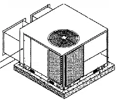
Ductwork Connections
The use of flexible, non-combustible connectors between
main trunk ducts and supply and return air plenums is
recommended to minimize vibration transmission.
NOTE: Connect supply and return air plenums to unit in a
manner that will allow the top of the unit to be removed
without removing plenums. Plenums MUST be individually
sealed to unit casing with ducts terminating inside structure.
FILTERS
All return air MUST pass through a filter before entering the
unit. An electronic air cleaner, optional filter racks, or other
accessible filter arrangement MUST be installed in the
return air ductwork. Minimum recommended filter areas
are listed in FIGURE 8 and are based on a velocity of 325
ft/min for disposable filters and 525 ft/min for high velocity
filters (washable).
CAUTION
DO NOT OPERATE THE UNIT WITHOUT A FILTER.
9. START-UPPROCEDURES
Fire and/or explosion hazard.
FIGURE 9 1
Inlet Pressure
Tap (Hidden)
Honeywell Gas Valve
On/Off Switch
Ignitor
Wiring
Harness
INLET -Control
\ Wiring
• Harness
Outlet
Pressure
Tap
Pilot Adjustment
OUTLET
Do NOT attempt to light the pilot or burner with a match or
flame of any kind.
Failure to follow this warning can result in property damage,
personal injury, and/or death.
CHECK BEFORE STARTING
1. Check that the blower motor speed terminal block is
running the correct heating and cooling speeds.
2. Check to see that clean, properly sized air filters are
installed.
3. Replace all service access panels.
Reverse Rotation (Scroll Compressors Only)
Three phase scroll compressor equipped units CAN run in
reverse if improperly wired. If the compressor makes an
unusually loud noise, or if high and low side pressures are
nearly identical, this indicates reverse rotation. To correct,
reverse any two wires at line voltage connections ONLY. Do
NOT re-wire any circuits inside the unit to attempt
correction of reverse rotation.
Manifold Gas Pressure Adjustment
NOTE: Make adjustment to manifold pressure with burners
operating.
Fire or explosion hazard.
Turn OFF gas at shut off before connecting U-tube ma-
nometer.
Failure to properly seal duct can result in personal injury
and/or death.
GAS PRESSURES
1. Do NOT allow gas supply pressure to fall below the
listed minimums. Doing so will decrease input to fur-
nace. Refer to FIGURE 10 for gas supply pressures.
2. Gas input MUST NOT exceed rated input shown on rat-
ing plate.
3. Do NOT allow pressures to exceed the maximum limits
as listed in FIGURE 10.
FIGURE 10 Gas Pressures
Natural Gas LP Gas
Minimum 4.5"W.C. (1120 Pa) 11" W.C. (2740 Pa)
Inlet
Recommended 7" W.C. (1740 Pa) 11" W.C. (2740 Pa)
Inlet
Maximum 13" w.c. (3230 Pa) 13" W.C. (3230 Pa)
Inlet
Manifold 3.5" W.C. (870 Pa) 10" W.C. (2490 Pa)
Pressure
Manifold Pressures
Manifold pressures are covered in the startup procedure
section. Refer to Chapter 9 Start-Up Procedures.
1. With gas OFE Connect U-Tube manometer to tapped
opening on gas valve. Use manometer with a 0 to 12
inches water column range.
FIGURE 11 Manifold Pressure Settings
Gas Type Manifold Pressure
Natural 3.5 Inches Water Column (870 Pa)
Propane 10 Inches Water Column (2490 Pa)
462 01 1003 01 191
Loading ...
Loading ...
Loading ...
