Loading ...
Loading ...
Loading ...
7. ELECTRICAL WIRING
Electrical shock hazard.
Disconnect power at fuse box or service panel before making
any electrical connections.
Unit MUST be grounded to electrical service panel.
Failure to follow this warning can result in property damage,
personal injury, and/or death.
NOTE: All electrical work MUST conform with the
requirements of local codes and ordinances and the
National Electrical Code ANSIiNFPA-No. 70-1990 or
current edition. Provide line voltage power supply from a
separate fused circuit with a disconnect switch located
within sight of the unit.
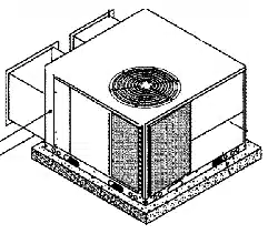
For access, remove the burner access panel. See
FIGURE 1 for access panel location. Wiring MUST be
protected from possible mechanical damage.
Line Voltage Wiring
Connections for line voltage are made in the unit control box
area. For access, remove the burner access panel.
Ground Connections
Do NOT complete line voltage connections until unit is
permanently grounded. All line voltage connections and the
ground connection MUST be made with copper wire.
A ground lug is installed in the control box area for the
appropriate size from the unit to a grounded connection in
the electrical service panel or a properly driven and
electrically grounded ground rod. See warning above.
Line Connections
Complete the line service connections to the contactor 'L'
terminals inside the control box area. Refer to applicable
wiring diagram. Check all screw terminals to ensure they
are tight.
THERMOSTAT/HEAT ANTICIPATOR
The location ofthe thermostat has an important effect onthe
operation of the unit. FOLLOW THE INSTRUCTIONS
INCLUDED WITH THE THERMOSTAT FOR CORRECT
MOUNTING AND WIRING.
Set the thermostat heat anticipator in accordance with
thermostat instructions.
Final Electrical Check
1. Make a final wiring check to be sure system is correctly
wired. Inspect field installed wiring and the routing to
ensure that rubbing or chafing due to vibration will not
Occur.
NOTE: Wiring MUST be installed so it is protected from
possible mechanical damage.
8. DUCTWORK
Maximum recommended velocity in trunk ducts is 1000 feet
per minute. Velocity in branches should not exceed 800 feet
per minute.
round connection, Use a copper conductor of the
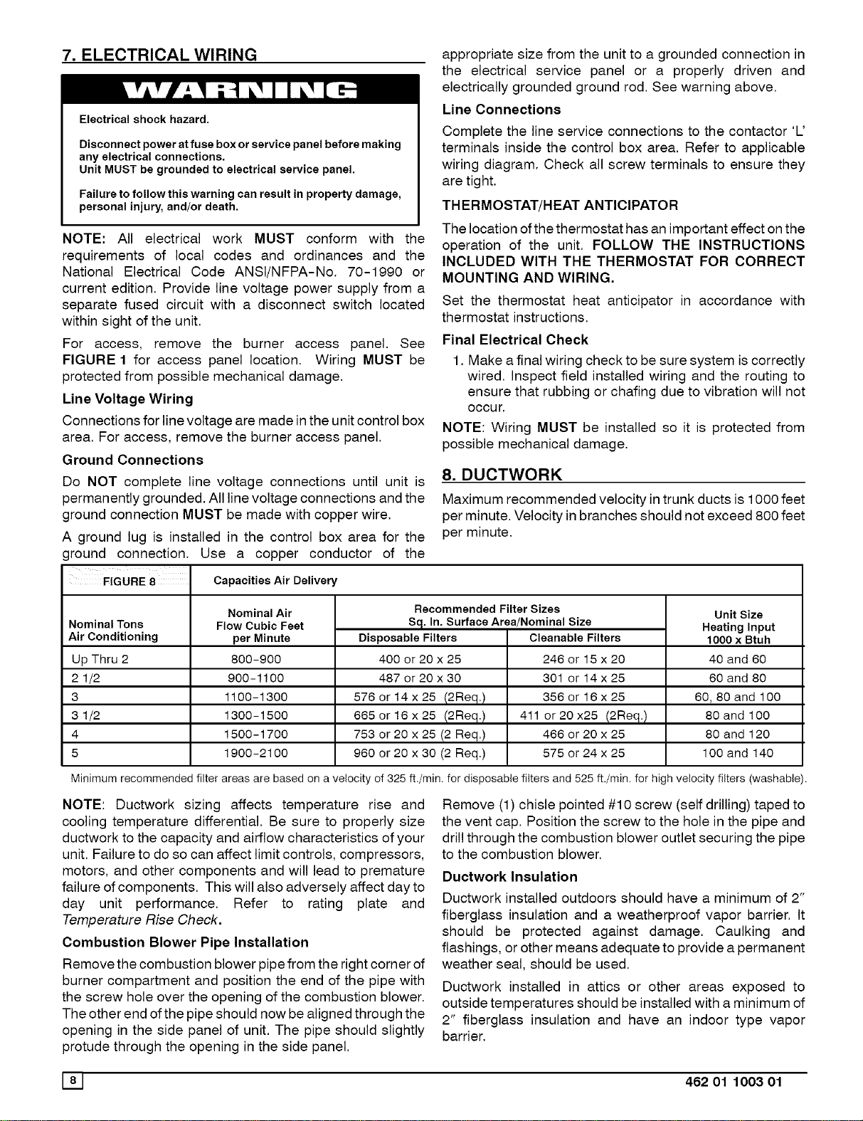
FIGURE 8 Capacities Air Delivery
Nominal Tons
Air Conditioning
Up Thru 2
2 1/2
3
3 1/2
4
5
Nominal Air
Flow Cubic Feet
per Minute
800-900
900-1100
1100-1300
1300-1500
1500-1700
1900-2100
Recommended Filter Sizes
Sq. In. Surface Area/Nominal Size
Disposable Filters
400 or 20 x 25
487 or 20 x 30
576 or 14 x 25 (2Req.)
565 or 16 x 25 (2Req.)
753 or 20 x 25 (2 Req.)
960 or 20 x 30 (2 Req.)
Cleanable Filters
246 or15x20
301 or 14x25
356 or16x25
411 or 20 x25 (2Req.)
466 or 20 x 25
575 or 24 x 25
UnitSize
Heatinglnput
1000 x Btuh
40 and 60
60 and 80
60, 80 and 100
80 and 100
80 and 120
100 and 140
Minimum recommended filter areas are based on a velocity of 325 ft,/min, for disposable filters and 525 ft./min, for high velocity filters (washable).
NOTE: Ductwork sizing affects temperature rise and
cooling temperature differential. Be sure to properly size
ductwork to the capacity and airflow characteristics of your
unit. Failure to do so can affect limit controls, compressors,
motors, and other components and will lead to premature
failure of components. This will also adversely affect dayto
day unit performance. Refer to rating plate and
Temperature Rise Check.
Combustion Blower Pipe Installation
Remove the combustion blower pipe from the right corner of
burner compartment and position the end of the pipe with
the screw hole over the opening of the combustion blower.
The other end of the pipe should now be aligned through the
opening in the side panel of unit. The pipe should slightly
protude through the opening in the side panel.
Remove (1) chisle pointed #10 screw (self drilling) taped to
the vent cap. Position the screw to the hole in the pipe and
drill through the combustion blower outlet securing the pipe
to the combustion blower.
Ductwork Insulation
Ductwork installed outdoors should have a minimum of 2"
fiberglass insulation and a weatherproof vapor barrier. It
should be protected against damage. Caulking and
flashings, or other means adequate to provide a permanent
weather seal, should be used.
Ductwork installed in attics or other areas exposed to
outside temperatures should be installed with a minimum of
2" fiberglass insulation and have an indoor type vapor
barrier.
W 462 01 1003 01
Loading ...
Loading ...
Loading ...