Loading ...
Loading ...
Loading ...
should glow orange (after about five minutes of operation).
Main burner flame should be inspected monthly.
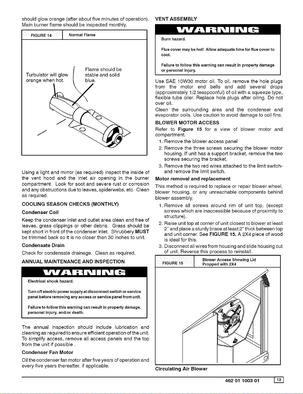
F,GuREi4[ .orma,F,ame
Turbulator will glow
orange when hot.
Flame should be
stable and solid
blue.
Using a light and mirror (as required) inspect the inside of
the vent hood and the inlet air opening in the burner
compartment. Look for soot and severe rust or corrosion
and any obstructions due to leaves, spiderwebs, etc. Clean
as required.
COOLING SEASON CHECKS (MONTHLY)
Condenser Coil
Keep the condenser inlet and outlet area clean and free of
leaves, grass clippings or other debris. Grass should be
kept short in front of the condenser inlet. Shrubbery MUST
be trimmed back so it is no closer than 30 inches to unit.
Condensate Drain
Check for condensate drainage. Clean as required.
ANNUAL MAINTENANCE AND INSPECTION
Electrical shock hazard.
Turn off electric power supply at disconnect switch or service
panel before removing any access or service panel from unit.
Failure to follow this warning can result in property damage,
personal injury, and/or death.
The annual inspection should include lubrication and
cleaning as required to ensure efficient operation of the unit.
To simplify access, remove all access panels and the top
from the unit if possible.
Condenser Fan Motor
Oil the condenser fan motor after five years of operation and
every five years thereafter, if applicable,
VENT ASSEMBLY
Burn hazard.
Flue cover may be hot! Allow adequate time for flue cover to
cool.
Failure to follow this warning can result in property damage
or personal injury.
Use SAE 10W30 motor oil. To oil, remove the hole plugs
from the motor end bells and add several drops
(approximately 1/2 teaspoonful) of oil with a squeeze type,
flexible tube oiler. Replace hole plugs after oiling. Do not
over oil,
Clean the surrounding area and the condenser and
evaporator coils. Use caution to avoid damage to coil fins,
BLOWER MOTOR ACCESS
Refer to Figure 15 for a view of blower motor and
compartment.
1. Remove the blower access panel
2. Remove the three screws securing the blower motor
housing. If unit has a support bracket, remove the two
screws securing the bracket.
3. Remove the two red wires attached to the limit switch-
and remove the limit switch.
Motor removal and replacement
This method is required to replace or repair blower wheel,
blower housing, or any unreachable components behind
blower assembly.
1. Remove all screws around rim of unit top, (except
screws which are inaccessible because of proximity to
structure).
2. Raise unit top at corner of unit closest to blower at least
2" and place a sturdy brace at least 2" thick between top
and unit corner. See FIGURE 15. A 2X4 piece of wood
is ideal for this.
3. Disconnect all wires from housing and slide housing out
of unit. Reverse this process to reinstall.
FIGURE 15 Blower Access Showing Lid
Propped with 2X4
t
Circulating Air Blower
462 01 1003 01 1131
Loading ...
Loading ...
Loading ...