Loading ...
Loading ...
Loading ...
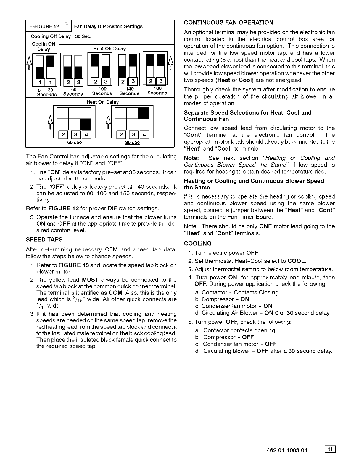
FIGURE 12 Fan Delay DIP Switch Settings
Cooling Off Delay : 30 Ssc.
Coolin ON
Delay
I
m_
0 30
Seconds
Heat Off Delay
60 100
Seconds Seconds
140
Seconds
180
Seconds
Heat On Delay
[][]1'1
30 sec
The Fan Control has adjustable settings for the circulating
air blower to delay it "ON" and "OFF".
1. The "ON" delay is factory pre-set at 30 seconds, It can
be adjusted to 60 seconds.
2. The "OFF" delay is factory preset at 140 seconds. It
can be adjusted to 60, 100 and 150 seconds, respec-
tively,
Refer to FIGURE 12 for proper DIP switch settings.
3, Operate the furnace and ensure that the blower turns
ON and OFF at the appropriate time to provide the de-
sired comfort level,
SPEED TAPS
After determining necessary CFM and speed tap data,
follow the steps below to change speeds.
1, Refer to FIGURE 13 and locate the speed tap block on
blower motor.
2. The yellow lead MUST always be connected to the
speed tap block at the common quick connect terminal.
The terminal is identified as COM. Also, this is the only
lead which is 3/16" wide, All other quick connects are
1/4"wide.
3, If it has been determined that cooling and heating
speeds are needed on the same speed tap, remove the
red heating lead from the speed tap block and connect it
to the insulated male terminal on the black cooling lead.
Then place the insulated black female quick connect to
the required speed tap,
CONTINUOUS FAN OPERATION
An optional terminal may be provided on the electronic fan
control located in the electrical control box area for
operation of the continuous fan option. This connection is
intended for the low speed motor tap, and has a lower
contact rating (8 amps) than the heat and cool taps. When
the low speed blower lead is connected to this terminal, this
will provide low speed blower operation whenever the other
two speeds (Heat or Cool) are not energized.
Thoroughly check the system after modification to ensure
the proper operation of the circulating air blower in all
modes of operation.
Separate Speed Selections for Heat, Cool and
Continuous Fan
Connect low speed lead from circulating motor to the
"Cont" terminal at the electronic fan control. The
appropriate motor leads should already be connected to the
"Heat" and "coor' terminals.
Note: See next section "Heating or Cooling and
Continuous Blower Speed the Same" if low speed is
required for heating to obtain desired temperature rise,
Heating or Cooling and Continuous Blower Speed
the Same
If is is necessary to operate the heating or cooling speed
and continuous blower speed using the same blower
speed, connect a jumper between the "Heat" and "Cont"
terminals on the Fan Timer Board,
Note: There should be only ONE motor lead going to the
"Heat" and "Cont" terminals,
COOLING
1. Turn electric power OFF
2. Set thermostat Heat-Cool select to COOL.
3. Adjust thermostat setting to below room temperature.
4. Turn power ON, for approximately one minute, then
OFF During power application check the following:
a. Contactor - Contacts Closing
b. Compressor - ON
c. Condenser fan motor - ON
d. Circulating Air Blower - ON 0 or 30 second delay
5, Turn power OFF, check the following:
a. Contactor contacts opening.
b. Compressor - OFF
c, Condenser fan motor - OFF
d. Circulating blower - OFF after a 30 second delay,
462 01 1003 01 Illl
Loading ...
Loading ...
Loading ...