Loading ...
Loading ...
Loading ...
TOOLS REQUIRED FOR ASSEMBLY
(1) Hammer
(2) 1/2" Wrenches
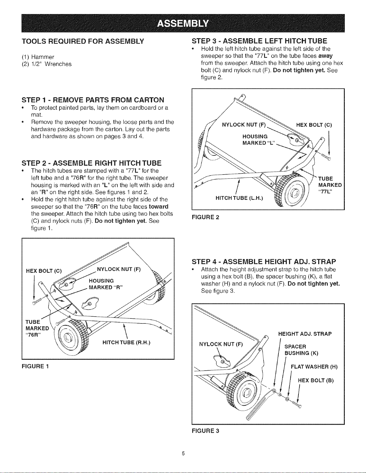
STEP 3 - ASSEMBLE LEFT HITCH TUBE
• Hold the left hitch tube against the left side of the
sweeper so that the "77L" on the tube faces away
from the sweeper. Attach the hitch tube using one hex
bolt (C) and nylock nut (F). Do riot tighten yet, See
figure 2.
STEP 1 = REMOVE PARTS FROM CARTON
To protect painted parts, lay them on cardboard or a
mat.
Remove the sweeper housing, the loose parts and the
hardware package from the carton. Lay out the parts
and hardware as shown on pages 3 and 4.
STEP 2 - ASSEMBLE RIGHT HITCH TUBE
The hitch tubes are stamped with a "77L" for the
left tube and a "76R" for the right tube. The sweeper
housing is marked with an "L" on the left with side and
an "R" on the right side. See figures 1 and 2.
Hold the right hitch tube against the right side of the
sweeper so that the "76R" on the tube faces toward
the sweeper. Attach the hitch tube using two hex bolts
(C) and nylock nuts (F). Do not tighten yet. See
figure 1.
NYLOCK NUT
HOUSING
MARKED
REX BOLT (C)
TUBE
MARKED
"771='
HITCH TUBE (L.H.)
FIGURE 2
HEX BOLT (C)
TUBE .._
MARKEB \
"76R"
HITCHTUBE(R.H.)
FIGURE 1
STEP 4 - ASSEMBLE HEIGHT ADJ. STRAP
Attach the height adjustment strap to the hitch tube
using a hex bolt (B), the spacer bushing (K), a flat
washer (H) and a nylock nut (F). Do not tighten yet.
See figure 3.
HEIGHT ADJ. STRAP
SPACER
BUSHING (K)
FLAT WASHER (H)
HEX BOLT (B)
FIGURE 3
Loading ...
Loading ...
Loading ...