
SE_/A/RS
®
MODEL NUMBER 917.259531
° Assembly
° Operation
oCustomer Responsibilities
Service and Adjustments
° Repair Parts
OWNER'S MANUAL
CAUTION: Read and follow all safety rules and instructions before operating this equipment.
FOR CONSUMER ASSISTANCE HOT LINE, CALL THIS TOLL FREE NUMBER: 1-800-659-5917
SAFETY RULES
Safe Operation Practices for Ride-On Mowers I_
IMPORTANT: THIS CUTTING MACHINE IS CAPABLE OF AMPUTATING HANDS AND FEET AND THROWING OBJECTS.
FAILURE TO OBSERVE THE FOLLOWING SAFETY INSTRUCTIONS COULD RESULT IN SERIOUS INJURY OR DEATH
I. GENERAL OPERATION
Read, understand, and follow all instructions in the manual
and on the machine before starting
Only allow responsible adults, who are familiar with the
instructions, to operate the machine.
Clear the area of objects such as rocks, toys, wire, etc.,
which could be picked up and thrown by the blade_
Be sure the area is clear of other people before mowing. Stop
machine if anyone enters the area.
Never carry passengers.
Do not mow in reverse unless absolutely necessary. Always
look down and behind before and while backing
Be aware of the mower discharge direction and do not point
it at anyone Do not operate the mower without either the
entire grass catcher or the guard in place
Slow down before turning.
Never leave a running machine unattended. Always turn off
blades, set parking brake, stop engine, and remove keys
before dismounting.
Turn off blades when not mowing
• Stop engine before removing grass catcher or unclogging
chute.
• Mow only in daylight or good artificial light
Do not operate the machine while under the influence of
alcohol or drugs
Watch for traffic when operating near or crossing roadways.
Use extra care when loading or unloading the machine into
a trailer or truck
II. SLOPE OPERAI'ION
Slopes are a major factor related to loss-of-control and
tipover accidents, which can result in severe injury ordeath.
All slopes require extra caution. If you cannot back up the
slope or if you feel uneasy on it, do not mow it.
DO:
Mow up and down slopes, not across.
Remove obstacles such as rocks, tree limbs, etc.
Watch for holes, ruts, or bumps. Uneven terrain could
overturn the machine, Tall grass can hide obstacles.
Use slow speed. Choose a low gear so that you will not have
to stop or shift while on the slope.
• Follow the manufacturer's recommendations for wheel
weights or counterweights to improve stability
• Use extra care with grass catchers or other attachments.
These can change the stability of the machine
Keep all movement on the slopes slowand gradual Do not
make sudden changes in speed or direction_
• Avoid starting or stopping on a slope. If tires lose traction,
disengage the blades and proceed slowly straight down the
slope.
DO NOT:
• Donotturnonslopesunlessnecessary, andthen, turnslowly
and gradually downhill, if possible.
• Do not mow near drep-offs, ditches, or embankments. The
mower could suddenly turn over if a wheel is over the edge
of a cliff or ditch, or if an edge caves in.
• Do not mow on wet grass. Reduced traction could cause
sliding.
Do not try to stabilize the machine by putting your foot on the
ground,
• Do not use grass catcher on steep slopes.
III. CHILDREN
Tragic accidents can occur if the operator is not alert to the
presence of children_ Children are often attracted to the
machine and the mowing activity Never assume that
children will remain where you last saw them.
Keep children out of the mowing area and under the watchful
care of another responsible adult
• Be alert and turn machine off if children enter the area
• Before and when backing, look behind and down for small
children
Never carry children. They may fall off and be seriously
injured or interfere with safe machine operation
Never allow children to operate the machine.
Use extra care when approaching blind corners, shrubs,
trees, or other objects that may obscure vision
IV. SERVICE
• Use extra care in handling gasoline and other fuels. Theyare
flammable and vapors are explosive
Use only an approved container.
Never remove gas cap or add fuel with the engine
running Allow engine to cool before refueling. Do not
smoke.
Never refuel the machine indoors.
Never store the machine or fuel container inside where
there is an open flame, such as a water heater
Never run a machine inside a closed area
Keep nuts and bolts, especially blade attachment bolts, tight
and keep equipment in good condition.
Never tamper with safety devices Check their proper
operation regularly
• Keep machine free of grass, leaves, or other debris build-up.
Clean oil or fuel spillage. Allow machine to cool before
storing.
• Stop and inspect the equipment if you strike an object
Repair, if necessary, before restarting
• Never make adjustments or repairs with the engine running
• Grass catcher components are subject to wear, damage, and
deterioration, which could expose moving parts or allow
ob ects to be thrown, Frequently check components and
rep ace with manu acturer's recommended parts, when nec-
essary.
Mower blades are sharp and can cut. Wrap the blade(s) or
wear gloves, and use extra caution when servicing them
• Check brake operation frequently, Adjust and service as
required.
A Look for this symbol to point out im-
portant safety precautions. It means
CAUTION!It BECOME ALERTIH YOUR
SAFETY IS INVOLVED.
A
CAUTION: Always disconnect spark plug
wire and place wire where it cannot contact
spark plug in order to prevent accidental
starting when setting up, transporting,
adjusting or making repairs,
2
A WARNING A
The engine exhaust from this product con-
tains cnemicals known to the State of Califor-
nia to cause cancer, birth defects, or other
reproductive harm.

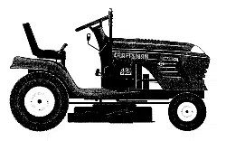
CONGRATULATIONS on your purchase of a Sears
Tractor. It has been designed, engineered and manufac-
tured to give you the best possible dependability and
performance,
Should you experience any problem you cannot easily
remedy, please contact your nearest Sears Authorized
Service CentedDepartmenL We have competent, well-
trained technicians and the proper tools to service or repair
this tractol_
Please read and retain this manual The instructions will
enable you to assemble and maintain your tractor properly.
Always observe the "SAFETY RULES'L
MODEL
NUMBER 917.259531
SERIAL
NUMBER
DATEOFPURCHASE
THEMODELANDSERIALNUMBERSWILLBEFOUND
ON A PLATE UNDER THE SEAT.
YOUSHOULDRECORDBOTHSERIALNUMBERAND
DATE OF PURCHASE AND KEEP IN A SAFE PLACE
FOR FUTURE REFERENCE.
MAINTENANCE AGREEMENT
A Sears Maintenance Agreement is available on this prod-
ucL Contact your nearest Sears store for details.
CUSTOMER RESPONSlBILRTIES
o Read and observe the safety rules.
o Fo!low a regular schedule in maintaining, caring for and
using your tractor.
= Follow the instructions under "Customer Responsibili-
ties" and "Storage" sections of this owner's manual
WARNING: This tractor is equipped with an internal
combustion engine and should not be used on or near any
PRODUCT SPECIFICAT ONS
HORSEPOWER: 15.5
GASOLINE CAPACITY 1.25 GALLONS
AND TYPE: UNLEADED REGULAR
OIL TYPE (API-BF/SG/SH): BAE 30 (above 32OF)
SAE 5W-30 (below 32°F)
OIL CAPACITY: 30 PINTS
SPARK PLUG: CHAMPION RJ19LM
3AP: 030")
VALVE CLEARANCE: INTAKE: 005" - .007"
EXHAUST: 009" - 011"
GROUND SPEED (MPH): FORWARD: 0- 55
REVERSE: 0-24
TIRE PRESSURE: FRONT: 14 PSI
REAR: 10 PS!
CHARGING SYSTEM: 3 AMPS BATTERY
5 AMPS HEADLIGHTS "
BATTERY: AMP/HR: 25
MIN CCA: 190
CASE SIZE: UtR
BLADE BOLT TORQUE: 30-35 FT LBS
unimproved forest-covered, brush-covered or grass-cov-
ered land unless the engine's exhaust system is equipped
with a spark arrester meeting applicable local or state laws
(if any), If a spark arrester is used, it should be maintained
in effective working order by the operator,
In the state of California the above is required by law
(Section 4442 of the California Public Resources Code).
Other states may have similar laws. Federal laws apply on
federal lands. A spark arrester for the muffler is available
through your nearest Sears Authorized Service Center/
Department (See REPAIR PARTS section of this manual).
LiMiTED TWO YEAR WARRANTY ON CRAFTSMAN RIDBNG EQUIPMENT
For two (2) years from the date of purchase, ifthis Craftsman Riding Equipment is maintained, lubricated and tuned up according
to the instructions in the owner's manual, Sears will repair or replace, free of charge, any parts found to be defective in material or
workmanship.
This Warranty does not cover:
Expendable items which become worn daring normal use, such as blades, spark plugs, air cleaners, belts, etc
Tire replacement or repair caused by punctures from outside objects, such as nails, thorns, stumps, or glass.
Repairs necessary because of operator abuse, negligence, improper storage or accident or the failure to maintain the
equipment according to the instructions contained in the owner's manual
Riding equipment used for commercial or rental purposes.
LUMaTED90 DAY WARRANTY ON BATTERY
For ninety (90) days from date of purchase, if any battery included with this riding equipment proves defective in material or
workmanship and our testing determines the battery will not hold a charge, Sears will replace the battery at no charge
IN-HOME WARRANTY SERVICE ON YOUR CRAFTSMAN RIDING EQUIPMENT iS AVAILABLE AT NO-CHARGE FOR 30
DAYS FROM THE DATE OF PURCHASE. PLEASE CONTACT YOUR NEAREST SERVICE CENTER. AFTER 30 DAYS FROM
THE DATE OF PURCHASE, WARRANTY SERVICE IS AVAILABLE BY TAKING YOUR CRAFTSMAN RIDING EQUIPMENT TO
YOUR NEAREST SEARS SERVICE CENTER. (IN-HOME WARRANTY SERVICE WILL STILL BE AVAILABLE AFTER 30 DAYS
FROM THE DATE OF PURCHASE BUT A STANDARD TRIP CHARGE WILL APPLY) THIS WARRANTY APPLIES ONLY
WHILE THIS PRODUCT IS IN THE UNITED STATES
This Warranty gives you specific legal rights, and you may also have other rights which may vary from state to state_
SEARS, ROEBUCK AND CO. D/817 WA, HOFFMAN ESTATES, IL 60179
3
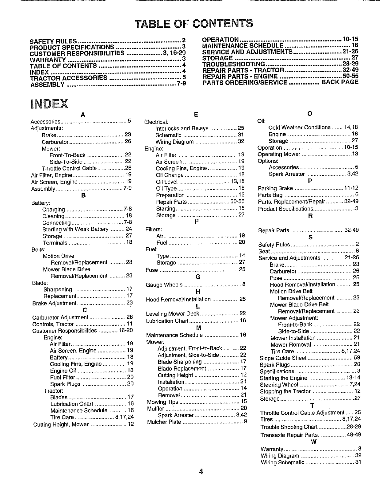
TABLE OF CONTENTS
SAFETY RULES ............................................................ 2
PRODUCT SPECIFICATIONS ...................................... 3
CUSTOMER RESPONSIBILITIES ..................... 3, 16-20
WARRANTY .................................................................. 3
TABLE OF CONTENTS ................................................ 4
INDEX ............................................................................ 4
TRACTOR ACCESSORIES .......................................... 5
ASSEMBLY ................................................................ 7-9
OPERATION ........................................................... 10-15
MAINTENANCE SCHEDULE ...................................... 16
SERVICE AND ADJUSTM ENTS ............................ 21-26
STORAGE ................................................................... 27
TROUBLESHOOTING ............................................ 28-29
REPAIR PARTS - TRACTOR ................................. 32-49
REPAIR PARTS- ENGINE .................................... 50-55
PARTS ORDERING/SERVICE .................. BACK PAGE
INDEX
A
Accessories ................................................ 5
Adjustments:
Brake ................................................ 23
Carburetor ....................................... 26
Mower:
Front-To-Back ........................ 22
Side-To-Side ............................ 22
Throttle Control Cable .................. 25
Air Filter, Engine ................................... 19
Air Screen, Engine ................................ 19
Assembly ........................................... 7.9
B
Battery:
Charging .................................... 7-8
Cleaning ........................................ 18
Connecting .................................. 7-8
Starting with Weak Battery ........ 24
Storage ........................................... 27
Terminals.., .............................. 18
Belts:
Motion Drive
RemovaVReplacement .............23
Mower Blade Drive
Removal/Replacement ...........23
Blade:
Sharpening ......................................17
Replacement .................................. 17
Brake Adjustment .................................. 23
c
Carburetor Adjustment ...................... 26
Controls, Tractor ............................... 11
Customer Responsibilities ............ 16-20
Engine:
Air Filter. .................................. 19
Air Screen, Engine ................. 19
Battery ..................................... 18
Cooling Fins, Engine .............. 19
Engine Oil ................................ 18
Fuel Filter ................................ 20
Spark Plugs ............................ 20
Tractor:
Blades ....................................... 17
Lubrication Chart .................... 16
Maintenance Schedule ........... 16
Tire Care ........................ 8,17,24
Cutting Height, Mower ....................... 12
E
Electrical:
Interlocks and Relays ................ 25
Schematic ..................................... 31
Wiring Diagram .............................. 32
Engine:
Air Filter .......................................... 19
Air Screen ..................................... 19
Cooling Fins, Engine ..................... 19
OIl Change ................................18
Oil Level ................................... 13,18
Oil Type ..............................................18
Preparation .....................................13
Repair Parts .......................... 50-55
Stading ........................................... 15
Storage ............................................27
F
Filters:
Air ................................................. 19
Fuel ............................................... 20
Fuel:
Type ................................................ 14
Storage ............................................... 27
Fuse .....................................................25
G
Gauge Wheels .........................................8
H
Hood RemovaVInstallation ....................25
L
Leveling Mower Deck ........................22
Lubdcal(on Chart ................................ 16
M
Maintenance Schedule ._.................... 16
Mower:
Adjustment, Front-to-Back .......... 22
Adjustment, Side4o-Side ............. 22
Blade Sharpening .........................17
Blade Replacement .................... 17
Cutting Height ................................ 12
Installation ....................................2t
Operation ...................................... 14
Removal ...................................... 21
Mowing Tips ....................................... 15
Muffler .....'........................................... 20
Spark Arrester ............................ 3,42
Mulcher Plate .......................................... 9
4
O
Oil:
Cold Weather Conditions ........ 14,18
Engine ............................................... 18
Storage ............................................27
Operation ........................................ 10-15
Operating Mower .................................. 13
Options:
Accessodes ...................................... 5
Spark Arrester ...........................3,42
P
Parking Brake ............................... 11-12
Paris Bag .............................................6
Parts, Replacement/Repair .............32-49
Product Specifications ............................3
R
Repair Parts ..................................... 32-49
S
Safety Rules ........................................... 2
Seat ...........................................................8
Service and Adjustments ...............21-26
Brake..............................................23
Carburetor ..........................................26
Fuse ............................................25
Hood Removal/Installation...........25
MotionDriveBelt
Removal/Replacement .......... 23
Mower Blade Drive Belt
Removal/Replacement ............23
Mower Adjustment:
Front-to-Back ......................... 22
Side-to-Side .......................... 22
Mower Installation .........................21
Mower Removal ............................ 21
Tire Care ............................. 8,17,24
Slope Guide Sheet .............................. 59
Spark Plugs ........................................ 20
Specifications .......................................... 3
Starting the Engine ....................... 13-14
Steering Wheel .................................. 7,24
Stopping the Tractor. ............................ 12
Storage ...................................................27
T
Throttle Control Cable Adjustment.._. 25
Tires .............................................. 8,17,24
Trouble Shooting Chart ....................28-29
Transaxle Repair Parts ................. 48-49
W
Warranty .................................................3
Wiring Diagram .......................................32
Wiring Schematic ................................ 31
ACCESSORIES AND ATTACHMENTS;
These accessories and attachments were available through most Sears retail outlets and service centers when the tractor was purchased_
Most Sears stores can order these items for you when you provide the model number of your tractor.
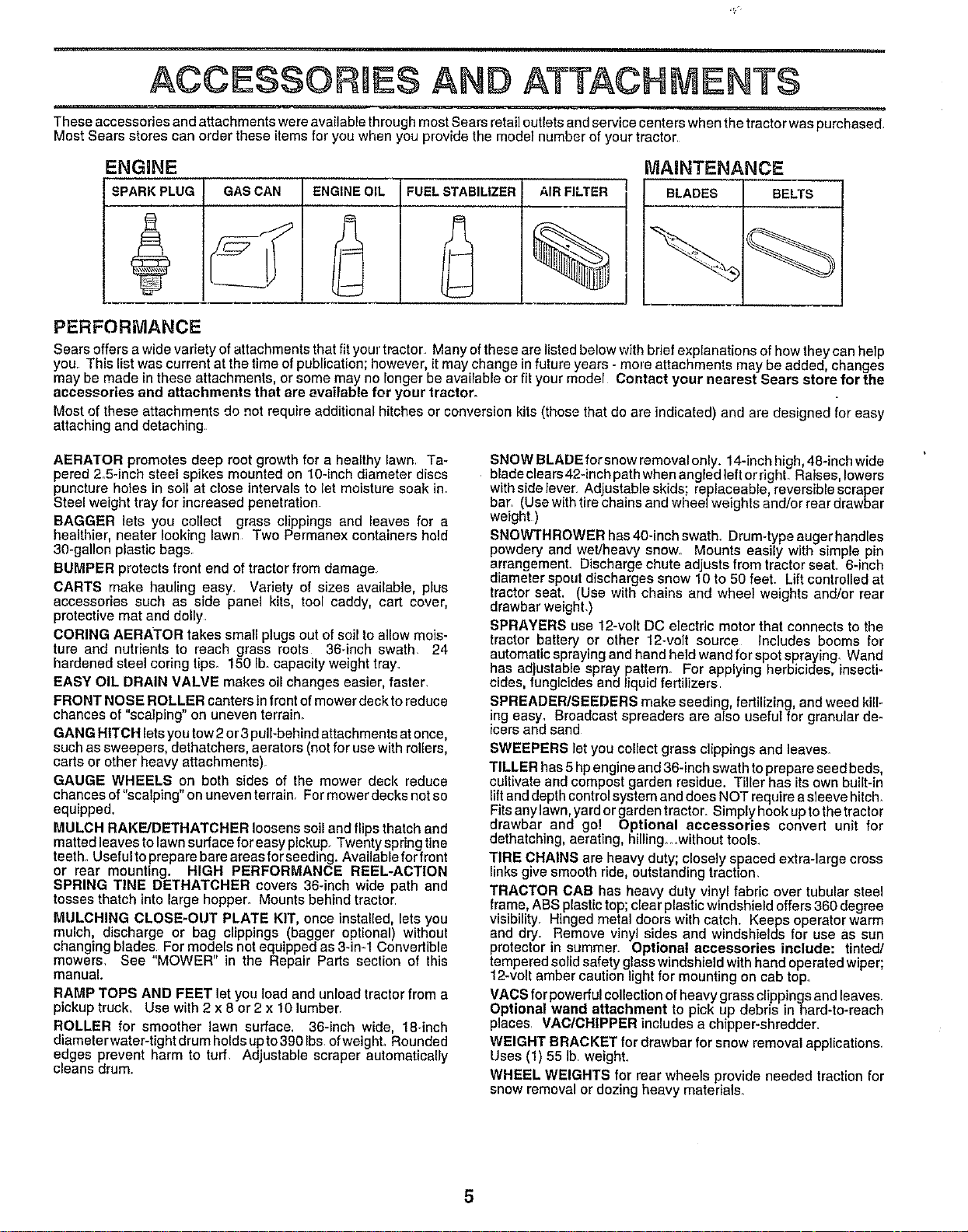
ENGINE MAINTENANCE
SPARK PLUG GAS CAN ENGINE OIL FUEL STABILIZER AIRFILTER BLADES BELTS
PERFORIVlANCE
Sears offers a wide variety of attachments that fit your tractor Many of these are listed below with brief explanations of how they can help
you This list was current at the time of publication; however, it may change infuture years - more attachments may be added, changes
may be made in these attachments, or some may no longer be available or fit your model Contact your nearest Sears store for the
accessories and attachments that are available for your tractor.
Most of these attachments do not require additional hitches or conversion kits (those that do are indicated) and are designed for easy
attaching and detaching
AERATOR promotes deep root growth for a healthy lawn Ta-
pered 2.5-inch steel spikes mounted on 10-inch diameter discs
puncture holes in soil at close intervals to let moisture soak in.
Steel weight tray for increased penetration
BAGGER lets you collect grass clippings and leaves for a
healthier, heater looking lawn Two Permanex containers hold
30+gallon plastic bags+
BUMPER protects front end of tractor from damage
CARTS make hauling easy, Variety of sizes available, plus
accessories such as side panel kits, tool caddy, cart cover,
protective mat and dolly
CORING AERATOR takes small plugs out of soil to allow mois-
ture and nutrients to reach grass roots 36-inch swath 24
hardened steel coring tips. 150 Ib+capacity weight tray+
EASY OIL DRAIN VALVE makes oil changes easier, faster.
FRONT NOSE ROLLER canters in front of mower deck to reduce
chances of "scalping" on uneven terrain+
GANG HITCH lets you tow 2 or 3 pull-behind attachments at once,
such as sweepers, dethatchers, aerators (not for use with rollers,
carts or other heavy attachments)+
GAUGE WHEELS on both sides of the mower deck reduce
chances of"scalping" on uneven terrain For mower decks not so
equipped.
MULCH RAKE/DETHATCHER loosens soil and flips thatch and
matted leaves to lawn surface for easy pickup. Twenty spring tine
teeth. Useful to prepare bare areas for seeding. Available for front
or rear mounting. HIGH PERFORMANCE REEL-ACTION
SPRING TINE DETHATCHER covers 36-inch wide path and
tosses thatch into large hopper. Mounts behind tractor
MULCHING CLOSE+OUT PLATE KIT, once installed, lets you
mulch, discharge or bag clippings (bagger optional) without
changing blades For models not equipped as 3-in-1 Convertible
mowers_ See "MOWER" in the Repair Parts section of this
manual.
RAMP TOPS AND FEET let you load and unload tractor from a
pickup truck. Use with 2 x 8 or 2 x 10 lumber.
ROLLER for smoother lawn surface. 36-inch wide, 18+inch
diameter water-tight drum holds upto 390 Ibs ofweighL Rounded
edges prevent harm to turf Adjustable scraper automatically
cleans drum.
SNOW BLADE forsnow removal only. 14-inch high, 48+inch wide
bladeclears42-inchpathwhenangledleftorright. Raises lowers
with side lever. Adjustable skids: replaceable, reversible scraper
bar_ (Use with tire chains and wl_eel weights and/or rear drawbar
weight )
SNOWTHROWER has 40-inch swath. Drum-type auger handles
powdery and wet/heavy snow. Mounts easily with simple pin
arrangement Discharge chute adjusts from tractor seat. 6-inch
diameter spout discharges snow 10 to 50 feet. Lift controlled at
tractor seat. (Use with chains and wheel weights and/or rear
drawbar weight.)
SPRAYERS use 12-volt DC electric motor that connects to the
tractor battery or other 12-volt source Includes booms for
automatic spraying and hand held wand for spot spraying. Wand
has adjustable spray pattern. For applying herbicides, insecti-
cides, fungicides and liquid fertilizers
SPREADER/SEEDERS make seeding fertilizing and weed kill-
ing easy, Broadcast spreaders are also useful for granular de-
icers and sand
SWEEPERS let you collect grass clippings and leaves.
TILLER has 5 hp engine and 36-inch swath to prepare seed beds,
cultivate and compost garden residue, Tiller has its own built-in
lift and depth control system and does NOT require a sleeve hitch.
Fits any lawn, yard or garden tractor+ Simply hook up to the tractor
drawbar and go! Optional accessories convert unit for
dethatcMng, aerating, hilling+ +without tools.
TIRE CHAINS are heavy duty closely spaced extra-large cross
!nks g ve smooth ride, outstanding traction.
TRACTOR CAB has heavy duty vinyl fabric over tubular steel
frame, ABS plastic top; clear plastic windshield offers 360 degree
visibility. Hinged metal doors with catch. Keeps operator warm
and dry. Remove vinyl sides and windshields for use as sun
protector in summer. Optional accessories include: tinted/
tempered solid safety glass windshield with hand operated wiper;
12-volt amber caution light for mounting on cab top.
VACS for powerful collection of heavy grass clippings and leaves.
Optional wand attachment to pick up debris in hard-to-reach
places VAO/OHIPPER includes a chipper+shredder.
WEIGHT BRACKET for drawbar for snow removal applications.
Uses (1) 55 Ib weighL
WHEEL WEIGHTS for rear wheels provide needed traction for
snow removal or dozing heavy matedals_
5
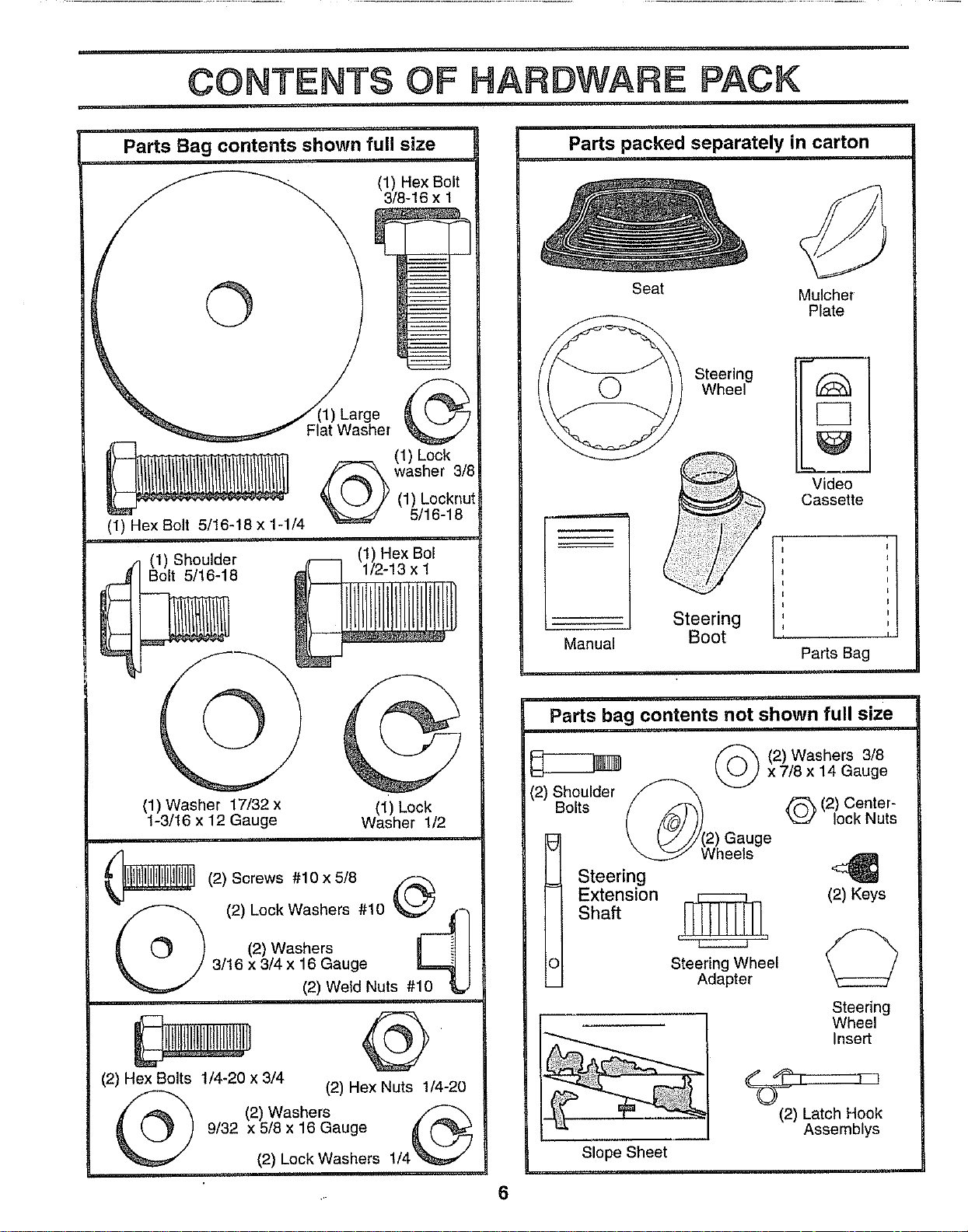
CONTENTS OF PACK
Parts Bag contents shown full size
(1) Hex Bolt
3/8-16 x 1
©
(1) Hex Bolt 5/16-18 x 1-1/4
(1) Shoulder
j Bolt 5/16-18
Large
Flat Washer
(1) Lock
washer 3/8
(1) Locknut
5/16-18
(1) Hex Bol
1/2-13 x I
(1) Washer 17/32 x
1-3/16 x 12 Gauge
(1) Lock
Washer 1/2
(2) Screws
#10 x 5/8
S'_... (2)Lock Washers #10 _../ _,-]
(_) (2) Washers H _4|
/ 3/16 x 3/4 x16 Gauge _ I
(2) Weld Nuts #10
(2) Hex Bolts 1/4-20 x 3/4 (2) Hex Nuts 1/4-20
(2) Washers
9/32 x 5/8 x 16 Gauge
(2) Lock Washers 1/4
Parts packed separately in carton
Seat
Mulcher
Plate
Manual
Steering
Wheel
Steering
Boot
Eli
Video
Cassette
Pa_s Bag
Parts bag contents not shown full size
_ (2)Washers 3/8
\k J) x7/8x 14 Gauge
(2)
Shoulder
/ .fF',_ _ (2) Center-
Bolts
( /_/)] _ lock Nuts
\ _j'//(2) Gauge
Wheels
I teering
Extension
Shaft
lllIIlllll_, (2) Keys
i
Steering Wheel
Adapter
Steering
Wheel
Insert
Slope Sheet
(2) Latch Hook
Assemblys
6
BLY
Your new tractor has been assembled at the factory with exception of those parts left unassembied for shipping purposes.
To ensure safe and proper operation of your tractor all parts and hardware you assemble must be tightened securely, Use
the correct tools as necessary to insure proper tightness.
TOOLS REQUIRED FOR ASSEMBLY
A socket wrench set will make assembly easier. Standard
wrench sizes are listed
(2) 7/16" wrenches Phillips Screwdriver
(1) 1/2" wrench Tire pressure gauge
(1) 9/16" wrench Utility knife
(1) 3/4" Socket w/drive rachet
When right or left hand is mentioned in this manual, it
means when you are in the operating position (seated
behind the steering wheel).
TO REMOVE TRACTOR FROM CARTON
UNP_,CK CARTON
o Remove all accessible loose parts and parts cartons
from carton (See page 6).
. Cut, from top to bottom, along lines on all four corners
of carton, and lay panels flat.
o Check for any additional loose parts or cartons and
remove.
BEFORE ROLLINGTRACTOR OFF SKiD
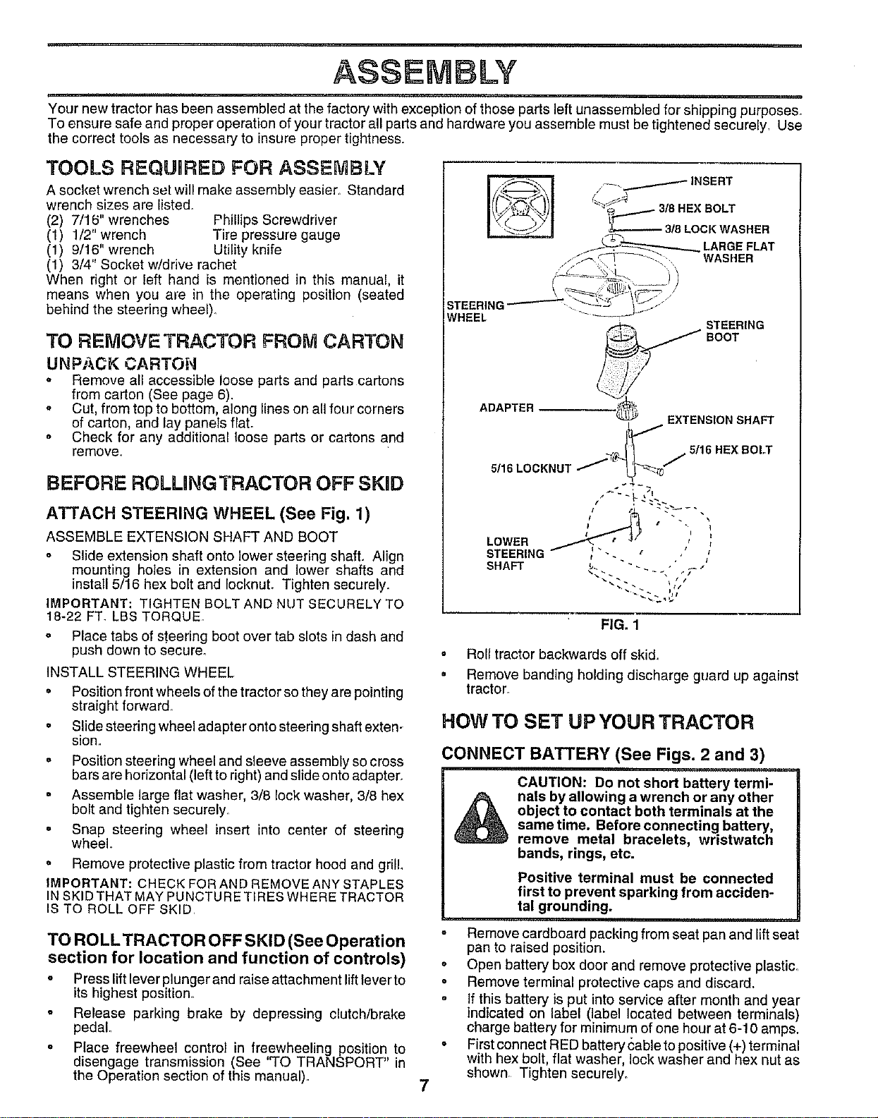
ATTACH STEERING WHEEL (See Fig, 1)
ASSEMBLE EXTENSION SHAFT AND BOOT
° Slide extension shaft onto lower steering shaft. Align
mounting holes in extension and lower shafts and
install 5/16 hex bolt and IocknuL Tighten securely.
IMPORTANT: TIGHTEN BOLT AND NUT SECURELY TO
18-22 FT. LBS TORQUE.
Place tabs of steering boot over tab slots in dash and
push down to secure.
INSTALL STEERING WHEEL
= Position front wheels of the tractor so they are pointing
straight forward.
= Slide steering wheel adapter onto steering shaft exten-
sion,,
= Position steering wheel and sleeve assembly so cross
bars are horizontal (left to right) and slide onto adapter.
= Assemble large flat washer, 3/8 lock washer, 3/8 hex
bolt and tighten securely.
° Snap steering wheel insert into center of steering
wheel.
° Remove protective plastic from tractor hood and grill.
IMPORTANT: CHECK FOR AND REMOVE ANY STAPLES
IN SKID THAT MAY PUNCTU RETIRES WHERE TRACTOR
IS TO ROLL OFF SKID
ADAPTER
STEERING
SOOT
EXTENSION SHAFT
5/16 LOCKNU'I
LOWER
STEERING
SHAFT
/ 5/16 HEX BOLT
I i
/ I
I_ _ ' _ / I
FIG. 1
• Roll tractor backwards off skid,
• Remove banding holding discharge guard up against
tractor.
HOW TO SET UP YOUR TRACTOR
CONNECT BATTERY (See Figs. 2 and 3)
&
CAUTION: Do not short battery termi-
nals by allowing a wrench or any other
object to contact both terminals at the
same time. Before connecting battery,
remove metal bracelets, wristwatch
bands, rings, etc.
Positive terminal must be connected
first to prevent sparking from acciden-
tal grounding.
TO ROLL TRACTOR OFF SKID (See Operation
section for location and function of controls)
" Press lift lever plunger and raise attachment lift lever to
its highest position°
° Release parking brake by depressing clutch/brake
pedal°
o Place freewheel control in freewheeling position to
disengage transmission (See "TO TRANSPORT" in
the Operation section of this manual).
7
° Remove cardboard packing from seat pan and lift seat
pan to raised position.
° Open battery box door and remove protective plastic.
• Remove terminal protective caps and discard.
If this battery is put into service after month and year
indicated on label (label located between terminals)
charge battery for minimum of one hour at 6-10 amps.
o First connect RED battery cable to positive (+) terminal
with hex bolt, flat washer, lock washer and hex nut as
shown, Tighten securely.
ASSEMBLY
SEAT
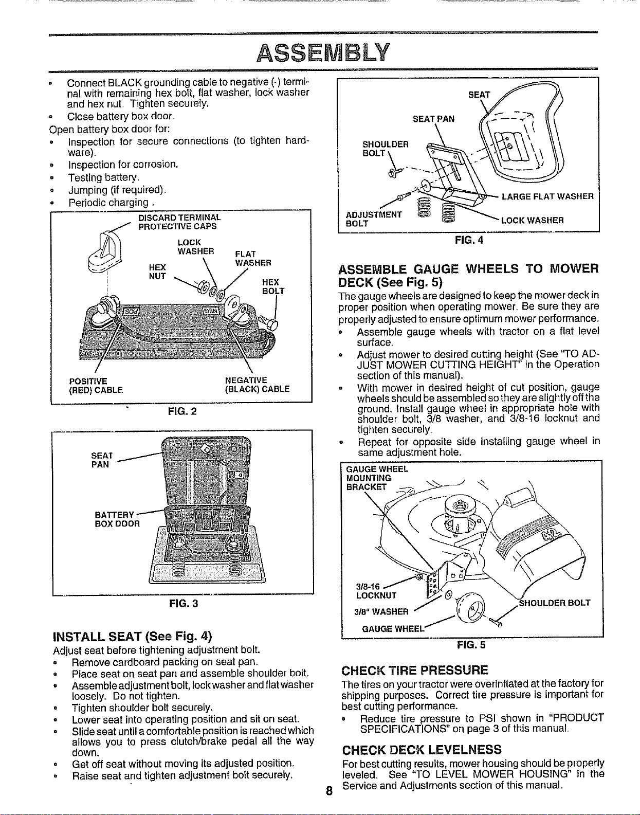
• Connect BLACK grounding cable to negative (-) terrni-
nal with remaining hex boiL, flat washer, lock washer
and hex nut. Tighten securely
° Close battery box docr_
Open battery box door for:
• Inspection for secure connections (to tighten hard-
ware).
Inspection for corrosion,
o Testing battery_
. Jumping (if required)_
Periodic charging
I
DISCARD TERMINAL
PROTECTIVE CAPS
LOCK
WASHER
HEX
NUT
FLAT
WASHER
HEX
BOLT
POSITIVE NEGATIVE
(RED)CABLE (BLACK)CABLE
FIG. 2
SEAT
PAN
BOX DOOR
FIG. 3
INSTALL SEAT (See Fig. 4)
Adjust seat before tightening adjustment bolt.
• Remove cardboard packing on seat pan_
° Place seat on seat pan and assemble shoulder bolt.
° Assemble adjustment bolt, lock washer and flat w'asher
loosely. Do not tighten.
• Tighten shoulder bolt securely,
• Lower seat into operating position and sit on seal
° Slide seat until a comfortable position is reached which
allows you to press clutch/brake pedal all the way
down.
o Get off seat without moving its adjusted position_
. Raise seat and tighten adjustment bolt securely_
SEAT PAN
SHOULDER
BOLT
FLAT WASHER
ADJUSTMENT
BOLT 'LOCK WASHER
FIG. 4
ASSEMBLE GAUGE WHEELS TO MOWER
DECK (See Fig. 5)
The gauge wheels are designed to keep the mower deck in
proper position when operating mower, Be sure they are
properly adjusted to ensure optimum mower performance.
o Assemble gauge wheels with tractor on a flat level
surface.
o Adjust mower to desired cutting height (See '`TO AD-
JUST MOWER CUTTING HEIGHT" in the Operation
section of this manual).
• With mower in desffed height of cut position, gauge
wheels should be assembled so they are slightly off the
ground. Install gauge wheel in appropriate hole with
shoulder bolt, 3/8 washer, and 3/8-16 Iocknut and
tighten securely
Repeat for opposite side installing gauge wheel in
same adjustment hole.
GAUGE WHEEL
MOUNTING
BRACKET _,
8
3/8-16
LOCKNUT
3/8"WASHER
GAUGE
FIG. 5
R BOLT
CHECK TIRE PRESSURE
The tires on yourtractor were overinflated at the factory for
shipping purposes. Correct tire pressure is important for
best cutting performance.
o Reduce tire pressure to PSI shown in "PRODUCT
SPECIFICATIONS" on page 3 of this manual
CHECK DECK LEVELNESS
Forbest cutting results, mower housing should be properly
leveled. See "TO LEVEL MOWER HOUSING" in the
Service and Adjustments section of this manual
ASSEMBLY
CHECK FOR PROPER POSITION OF ALL
BELTS
See the figures that are shown for replacing motion and
mower blade drive belts in the Service and Adjustments
section of this manual. Verify that the belts are routed
correctly,
CHECK BRAKE SYSTEM
After you learn how to operate your tractor, check to see
that the brake is properly adjusted. See 'q'O ADJUST
BRAKE" in the Service and Adjustments section of this
manual
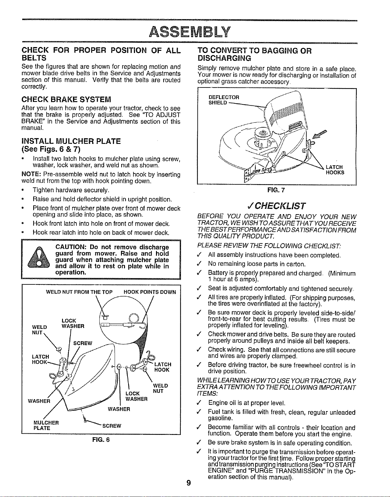
iNSTALL MULCHER PLATE
(See Figs. 6 & 7)
Install two latch hooks to mulcher plate using screw,
washer, lock washer, and weld nut as shown_
NOTE: Pre-assemble weld nut to latch hook by inserting
weld nut from the top with hook pointing down.
o Tighten hardware securely.
o Raise and hold deflector shield in upright position_
° Place front of mulcher plate over front of mower deck
opening and slide into place, as shown.
° Hook front latch into hole on front of mower deck_
Hook rear latch into hole on back of mower deck.
CAUTION: Do not remove discharge
guard from mower. Raise and hold
guard when attaching mulcher plate
and allow it to rest on plate whtle in
operation.
WELD NUT FROM THE TOP HOOK POINTS DOWN
LOCK
WELD WASHER
NUT_
LATCH
HOOK
WASHER
MULCHER
PLATE
LOCK
WASHER
WASHER
"_'_SCREW
WELD
NUT
FIG. 6
TO CONVERT TO BAGGING OR
DISCHARGING
Simply remove mulcher plate and store in a safe place.
Your mower is now ready for discharging or installation of
optional grass catcher accessory
DEFLECTOR
LATCH
HOOKS
9
FIG. 7
,/'CHECKLIST
BEFORE YOU OPERATE AND ENJOY YOUR NEW
TRACTOR, WE WISH TO ASSURE THAT YOU RECEIVE
THE BEST PERFORMANCE AND SATISFACTION FROM
THIS QUALITY PRODUCT.
PLEASE REVIEW THE FOLLOWING CHECKLIST"
v" All assembly instructionshave been completed.
,/ No remaining loose parts in carton.
,/ Batteryis proper,ly prepared and charged. (Minimum
1 hour at 6 amps).
,/ Seat is adjusted comfortably and tightened securely_
,/ All tires are properly inflated. (For shipping purposes
the tires were overinflated at the factory).
,/ Be sure mower deck is properly leveled side-to-side/
front-to-rear for best cutting results. (Tires must be
properly inflated for leveling),,
,/ Check mower and drive belts. Be sure they are routed
properly around pulleys and inside all belt keepers.
,I Check wiring. See that all connections are still secure
and wires are properly clamped.
,/ Before driving tractor, be sure freewheel control is in
drive position,
WHILE LEARNING HOW TO USE YOUR TRACTOR, PAY
EXTRA A TTENTION TO THE FOLLOWING IMPORTANT
ITEMS:
J Engine oil is at proper level.
,/ Fuel tank is filled with fresh, clean, regular unleaded
gasoline.
,/ Become familiar with all controls - their location and
function. Operate them before you start the engine.
,/ Be sure brake system is in safe operating condition.
v" !t isimportant to purge the transmission before operat-
ing your tractor for the first time. Follow proper starting
and transmission purging instructions(See'TO START
ENGINE" and "PURGE TRANSMISSION" in the Op-
eration section of this manual).
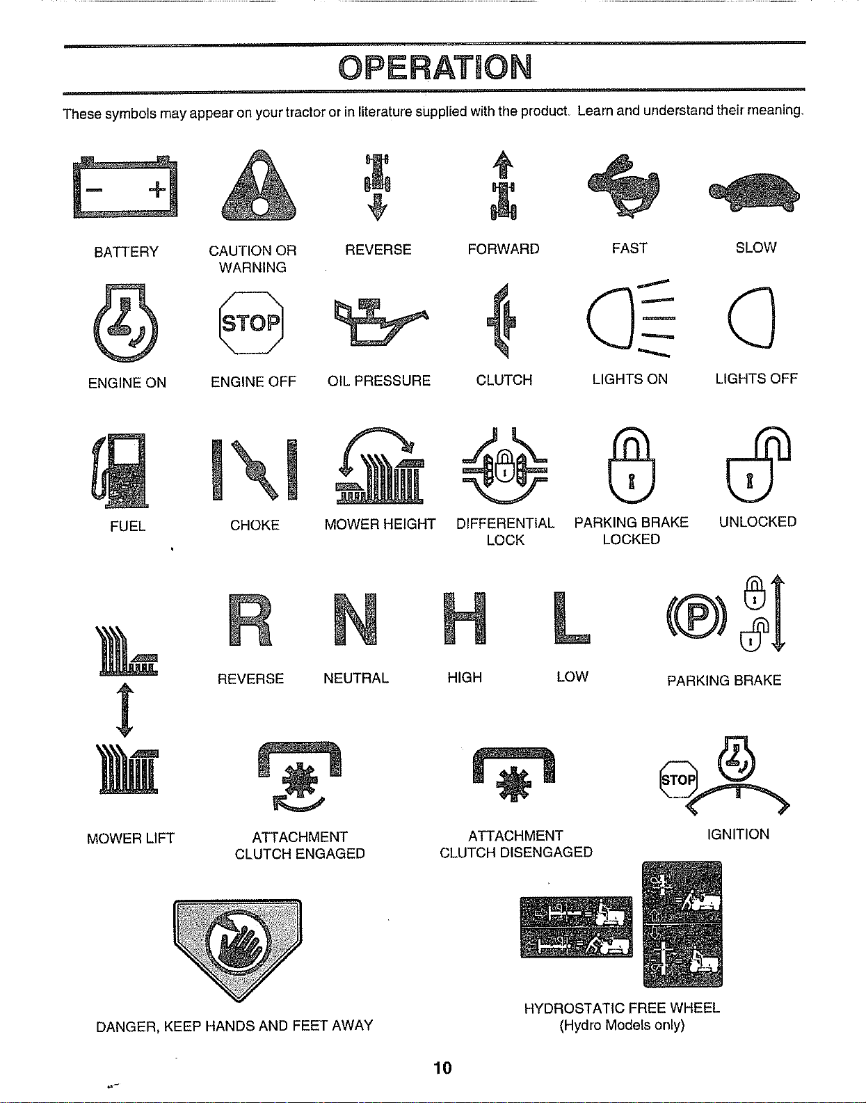
OPERATION
These symbols may appear on your tractor or in literature supplied with the product. Learn and understand their' meaning.
BATTERY CAUTION OR REVERSE
WARNING
ENGINE ON ENGINE OFF OIL PRESSURE
FORWARD
CLUTCH
FAST SLOW
LIGHTS ON LIGHTS OFF
FUEL
CHOKE
MOWER HEIGHT DIFFERENTIAL PARKING BRAKE UNLOCKED
LOCK LOCKED
MOWER LIFT
REVERSE NEUTRAL
ATTACHMENT
CLUTCH ENGAGED
H L
HIGH LOW
ATTACHMENT
CLUTCH DISENGAGED
PARKING BRAKE
IGNITION
DANGER, KEEP HANDS AND FEET AWAY
HYDROSTATIC FREE WHEEL
(Hydro Models only)
10
,r,
OPERATUON
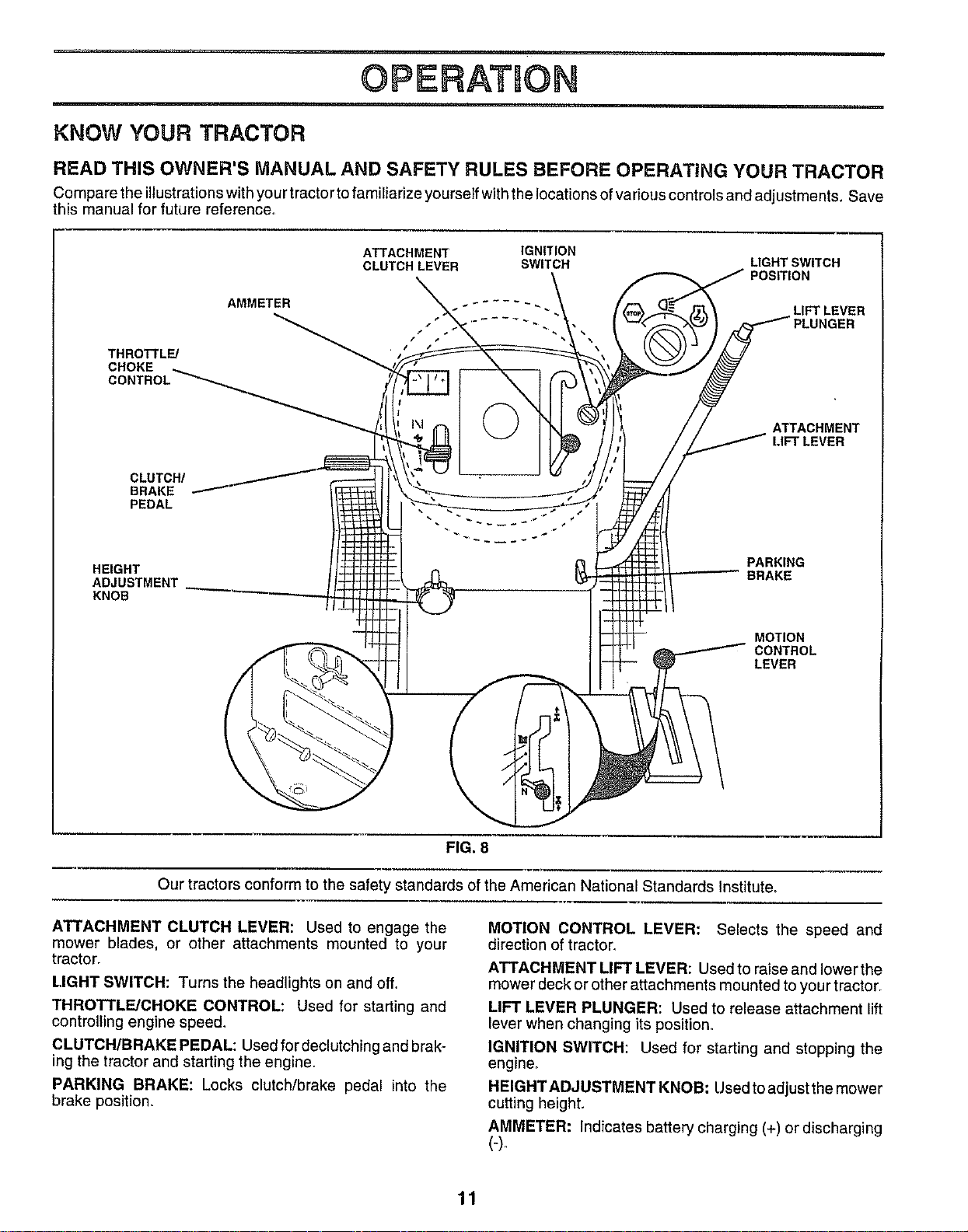
KNOW YOUR TRACTOR
READ THIS OWNER'S MANUAL AND SAFETY RULES BEFORE OPERATING YOUR TRACTOR
Compare the illustrations with your tractor to familiarize yourself with the locations of various controls and adjustments. Save
this manual for future reference,
ATTACHMENT IGNITION
CLUTCH LEVER SWITCH
LIGHT SWITCH
POSITION
LIFT LEVER
THROTTLE/
CHOKE
ATTACHMENT
LIFT LEVER
CLUTCH/
BRAKE
PEDAL
HEIGHT
ADJUSTMENT
KNOB
PARKING
BRAKE
MOTION
CONTROL
LEVER
FIG. 8
Our tractors conform to the safety standards of the American National Standards Institute,
ATTACHMENT CLUTCH LEVER: Used to engage the
mower blades, or other attachments mounted to your
tractor.
LIGHT SWITCH: Turns the headlights on and off,,
THROTTLE/CHOKE CONTROL: Used for starting and
controlling engine speed,
CLUTCH/BRAKE PEDAL: Used fordeclutching and brak_
ing the tractor and starting the engine.
PARKING BRAKE: Locks clutch/brake pedal into the
brake position.
MOTION CONTROL LEVER: Selects the speed and
direction of tractor,
ATTACHMENT LIFT LEVER: Used to raise and lower the
mower deck or other attachments mounted to your tractor.
LIFT LEVER PLUNGER: Used to release attachment lift
lever when changing its position,
IGNITION SWITCH: Used for starting and stopping the
engine_
HEIGHT ADJUSTMENT KNOB: Used to adjust the mower
cutting height.
AMMETER: Indicates battery charging (+) or discharging
11
OPERATSON
HOW TO USE YOUR TRACTOR
The operation of any tractor can result in foreign objects thrown into the eyes, which can
result in severe eye damage. Always wear safety glasses or eye shields while operating your
tractor or performing any adjustments or repairs. We recommend a wide vision safety mask
over the spectacles or standard safety glasses.
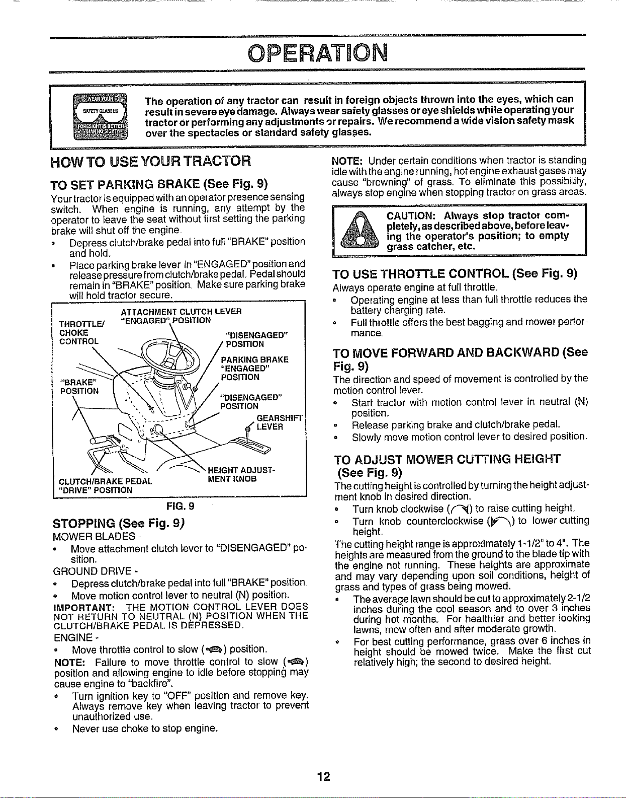
TO SET PARKING BRAKE (See Fig. 9)
Your tractor isequipped with an operator presence sensing
switch_ When engine is running, any attempt by the
operator to leave the seat without first setting the parking
brake will shut off the engine
• Depress clutch/brake pedal into full "BRAKE" position
and hold.
o Place parking brake lever in "ENGAGED" position and
release pressu refrom clutch/brake pedal. Pedal should
remain in "BRAKE" position_ Make sure parking brake
will hold tractor secure.
ATTACHMENT CLUTCH LEVER
"ENGAGED' POSITION
"DISENGAGED"
THROTTL_
CHOKE
CONTROL
JRAKE
"ENGAGED"
POSITION
POSITION
GEARSHIFT
"BRAKE"
POSITION
BEIGHTADJUST-
MENTKNOB
FIG. 9
CLUTCH/BRAKE PEDAL
"DRIVE" POSITION
STOPPING (See Fig. 9)
MOWER BLADES -
o Move attachment clutch lever to "DISENGAGED" po-
sition,
GROUND DRIVE -
• Depress clutch/brake pedal into full "BRAKE" position.
• Move motion control lever to neutral IN) position.
IMPORTANT: THE MOTION CONTROL LEVER DOES
NOT RETURN TO NEUTRAL IN) POSITION WHEN THE
CLUTCH/BRAKE PEDAL IS DEPRESSED_
ENGINE -
° Move throttle control to slow (,_,) position..
NOTE: Failure to move throttle control to slow !"e_)
position and allowing engine to idle before stopping may
cause engine to "backfire".
° Turn ignition key to "OFF" position and remove key.
Always remove key when leaving tractor to prevent
unauthorized use_
o Never use choke to stop engine.
NOTE: Under certain conditions when tractor is standing
idle with the engine running, hot engine exhaust gases may
cause "browning" of grass. To eliminate this possibility,
always stop engine when stopping tractor on grass area&
I
CAUTION: Always stop tractor com- |
pletely, as described above, before leav-
n
ing the operator's position; to empty
grass catcher, etc.
TO USE THROTTLE CONTROL (See Fig. 9)
Always operate engine at full throttle.
= Operating engine at less than full throttle reduces the
battery charging rate.
o Full throttle offers the best bagging and mower perfor-
mance,
TO MOVE FORWARD AND BACKWARD (See
Fig. 9)
The direction and speed of movement iscontrolled by the
motion control lever
• Start tractor with motion control lever in neutral IN)
position_
Release parking brake and clutch/brake pedal
o Slowly move motion control tever to desired position,
TO ADJUST MOWER CUTTING HEIGHT
(See Fig. 9)
The cuttingheight iscontrolled by turning the height adjust-
rnentknob in desired direction°
° Turn knob clockwise (('-'_) to raise cutting height°
° Turn knob counterclockwise (_e'_) to lower cutting
heighL
The cuttingheight range isapproximately t q/2" to4". The
heights are measured from the ground to the blade tip with
the engine not running. These heights are approximate
and may vary depending upon soil conditions, height of
grass and types of grass being mowed.
• The average lawn shouldbe cutto approximately 2-1/2
inches during the cool season and to over 3 inches
during hot months. For healthier and better looking
lawns, mow often and after moderate growth.
= For best cutting performance, grass over 6 inches in
height should be mowed twice. Make the first cut
relatively high; the second to desired height.
12
OPERATUON
=
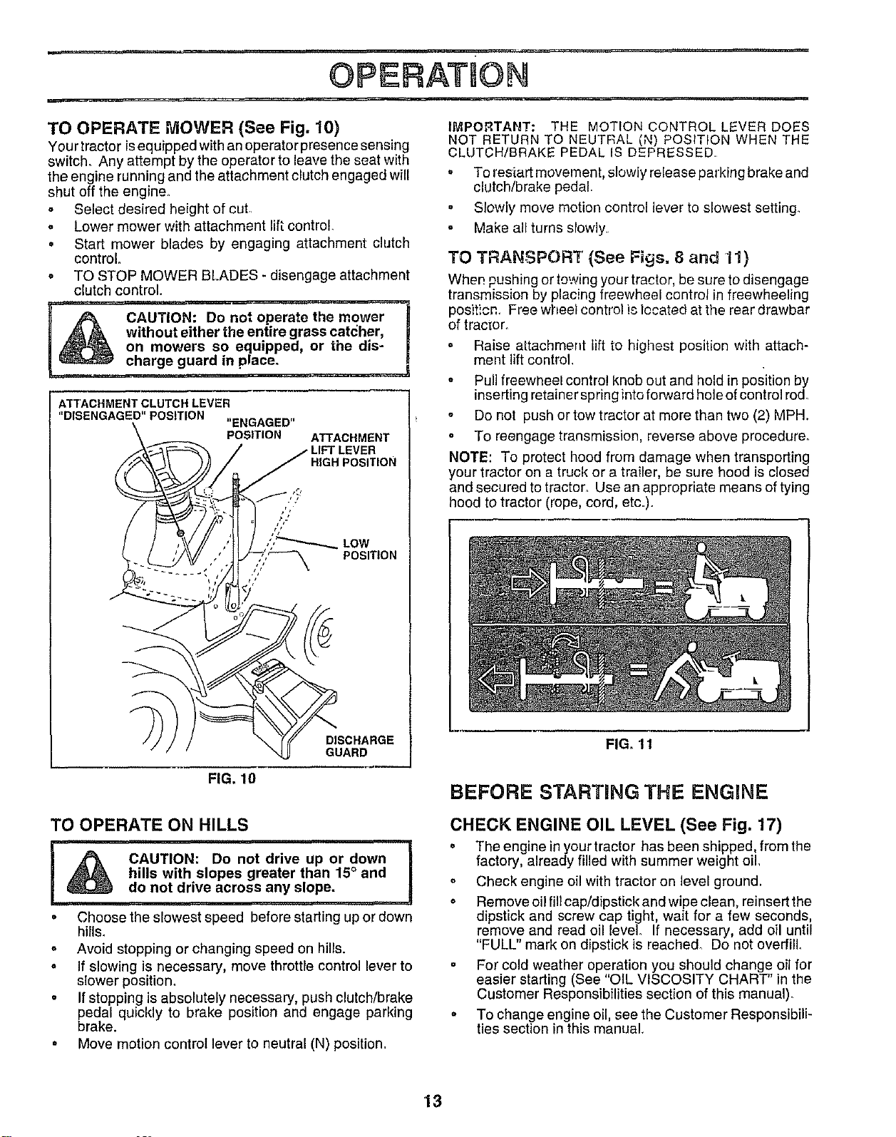
TO OPERATE MOWER (See Fig. 10)
Your tractor isequipped with an operatorpresence sensing
switch. Any attempt by the operator to leave the seat with
the engine running and the attachment clutch engaged will
shut off the engine_
Select desired height of cut
° Lower mower with attachmant lift control.
o Start mower blades by engaging attachment clutch
control
o TO STOP MOWER BLADES * disengage attachment
clutch control.
without either the entire grass catcher,
on mowers so equipped, or the dis-
charge guard in place.
_,TTACHMENT CLUTCH LEVER
"DISENGAGED" POSITION
"ENGAGED"
POSITION
ATTACHMENT
HIGH POSITION
DISCHARGE
GUARD
IMPORTAIIT: THE MOTION CONTROL LEVER DOES
NOT RETURN TO NEUTRAL (N) POSITION WHEN THE
CLUTCH/BRAKE PEDAL IS DEPRESSED•
o To resiart movement, slowly release parking brake and
clutch/brake pedal
Slowly move motion control lever to slowest setting.
° Make all turns slowly
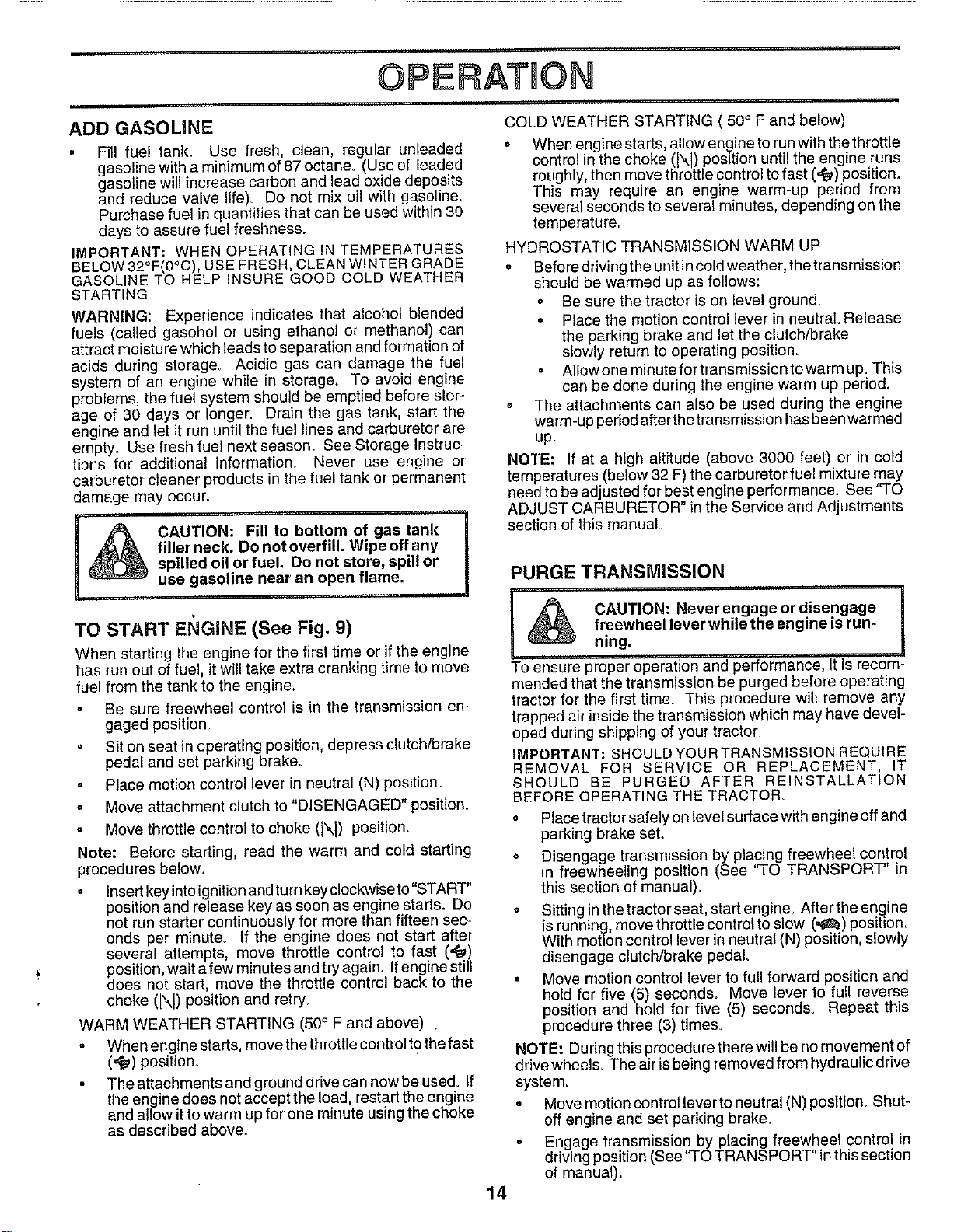
TO TRANSPORT (See Figs. 8 and 11)
When pushing or towing your tractor, be sure to disengage
transmission by placing freewheel control in freewheeling
posit!cn., Free wheel control is located at the rear drawbar
of tractor,
° Raise attachment lift to highest position with attach-
ment lift control.
o Pull freewheel control knob out and hold in position by
inserting retainer spring into forward hole ofcontrol rod.
o Do not push or tow tractor at more than two (2) MPH.
To reengage transmission, reverse above procedure_
NOTE: To protect hood from damage when transporting
your tractor on a truck or a trailer, be sure hood is closed
and secured to tractor. Use an appropriate means of tying
hood to tractor (rope, cord, etc.).
FIG. 11
FIG. 10
BEFORE STARTNNG THE ENGINE
TO OPERATE ON HILLS
I _ CAUTION: Do not drive up or down I
hills with slopes greater than 15° and
do not drive across any slope.
• Choose the slowest speed before starting up or down
hills.
° Avoid stopping or changing speed on hills.
o If slowing is necessary, move throttle control lever to
slower position_
• If stopping is absolutely necessary, push clutch/brake
pedal quickly to brake position and engage parking
brake.
o Move motion control lever to neutral (N) position.
CHECK ENGINE OIL LEVEL (See Fig. 17)
° The engine in yourtractor has been shipped, from the
factory, already filled with summer weight oil,
o Check engine oilwith tractor on level ground.
• Remove oilfill cap/dipstickand wipe clean, reinsert the
dipstick and screw cap tight, wait for a few seconds,
remove and read oil level. If necessary, add oil until
"FULL" mark on dipstick is reached_ Do not overfill
° For cold weather operation you should change oilfor
easier starting (See "OIL VISCOSITY CHART" in the
Customer Responsibilities section of this manual)_
= To change engine oil, see the Customer Responsibili-
ties section in this manual
13
OPERATmON
ADD GASOLINE
o Fill fuel tank Use fresh, clean, regular unleaded
gasoline with a minimum of87 octane° (Use of leaded
gasoline will irrcrease carbon and lead oxide deposits
and reduce valve life) Do not mix oil with gasoline.
Purchase fuel in quantities that can be used within 30
days to assure fuel freshness.
IMPORTANT: WHEN OPERATING IN TEMPERATURES
BELOW 32°F(0°C), USE FRESH, CLEAN WINTER GRADE
GASOLINE TO HELP INSURE GOOD COLD WEATHER
STARTING
WARNING: Experience indicates that alcohol blended
fuels (called gasohol or using ethanol or methanol) can
attract moisture which leads to separation and formation of
acids during storage_ Acidic gas can damage the fuel
system of an engine while in storage, To avoid engine
problems, the fuel system should be emptied before stor-
age of 30 days or longer, Drain the gas tank, start the
engine and let it run until the fuel lines and carburetor are
empty. Use fresh fuel next season. See Storage Instruc-
tions for additional information, Never use engine or
carburetor cleaner products in the fuel tank or permanent
damage may occur_
H
CAUTION: Fill to bottom of gas tank
filler neck. Do not overfill. Wipe off any
!
spilled oil or fuel. Do not store, spill or
use gasoline near an open flame.
TO START EI_GINE (See Fig. 9)
When starting the engine for the first time or if the engine
has run out of fuel, it will take extra cranking time to move
fuel from the tank to the engine.
= Be sure freewheel control is in the transmission en-
gaged position,
• Sit on seat in operating position, depress clutch/brake
pedal and set parking brake.
, Place motion control lever in neutral (N) position.
° Move attachment clutch to "DISENGAGED" position.
. Move throttle control to choke (l\l) position.
Note: Before starting, read the warn] and cold starting
procedures below.
o .... _t mt_
Insertkey rotetgnltlonand turn key clockwise to STAR
position arrd release key as soon as engine starts. Do
not run starter continuously for more than fifteen sec-
onds per minute° If the engine does not start after
several attempts move throttle control to fast (',_)
position,wait afewminutesandtryaga n. Ifengine still
does not start, move the throttle control back to the
choke (N) position and retry.
WARM WEATHER STARTING (50 ° F and above)
o When engine starts, move the throttle control t0 the fast
(._) position.
° The attachments and ground drive can now be used_ If
the engine does not accept the load, restart the engine
and allow itto warm upfor one minute using the choke
as described above.
COLD WEATHER STARTING ( 50° F and below)
= When engine starts, allow engine to run with thethrottle
control inthe choke (l\l) position until the engine runs
roughly, then move throttle control to fast (,,_) position.
This may require an engine warm-up period from
several seconds to several minutes, depending on the
temperature,
HYDROSTATIC TRANSMISSION WARM UP
. Before driving the urfit in cold weather, the transmission
should be warmed up as follows:
o Be sure the tractor is on level ground_
• Place the motion control lever in neutral Release
the parking brake and let the clutch/brake
slowly return to operating position_
Allow one minute for transmission to warm up. This
can be done during the engine warm up period.
• The attachments can also be used during the engine
warm-up per_odafter the transmission has been warmed
up.
NOTE: If at a high altitude (above 3000 feet) or in cold
temperatures (below 32 F) the carburetor fuel mixture may
need to be adjusted for best engine performance. See "TO
ADJUST CARBURETOR" in the Service and Adjustments
section of this manual
14
PURGE TRANSMISSION
_ CAUTION: Neverengageordisengage I
freewheel lever while the engine is run-
ning.
To ensure proper operation and performance, it is recom-
mended that the transmission be purged before operating
tractor for the first time. This procedure will remove any
trapped air inside the transmission which may have devel-
oped during shipping of your tractor_
IMPORTANT: SHOULD YOUR TRANSMISSION REQUIRE
REMOVAL FOR SERVICE OR REPLACEMENT, IT
SHOULD BE PURGED AFTER REINSTALLATION
BEFORE OPERATING THE TRACTOR
° Place tractor safely on level surface with engine off and
parking brake set.
o Disengage transmission by' placing freewheel control
in freewheeling position (See ''TO TRANSPORT" in
this section of manual).
o Sitting in the tractor seat, start engine. After the engine
s running move throttle control to slow (._,) position.
With motion control lever in neutra (N) position, slow y
disengage clutch/brake pedal.
° Move motion control lever to full forward position and
hold for five (5) seconds. Move lever to full reverse
position and hold for five (5) seconds° Repeat this
procedure three (3) times.
NOTE: During this procedure there will be no movement of
drive wheels. The air is being removed from hydraulic drive
system.
. Move motion controllever to neutral (N) position. Shut-
off engine and set parking brake.
° Engage transmission by placing freewheel control in
driving position (See "TO TRANSPORT" in this section
of manual).
OPERATNON
. Sitting inthetractor seat, start engine, Aftertheengine MULCHING MOWING TiPS
is running, move throttle control to half (1/2) speed.
With motion control lever in neutral (N) position, slowly
disengage clutch/brake pedal,,
Slowly move motion control lever forward, after the o
tractor moves approximately five (5) feet, slowly move
motion control lever to reverse position, After the
tractor moves approximately five (5) feet return the
motion control lever to the neutral (N) position. Repeat
this procedure with the motion control lever three (3)
times_
Your tractor is now purged and now ready for normal
cperation,
MOWING TiPS
Tire chains cannot be used when the mower housing
is attached to tractor
• Mower should be properly leveled for best mowing
performance. See "TO LEVEL MOWER HOUSING" in
the Service and Adjustments section of this manual
• The left hand side of mower should be used for trim-
ming.
° Drive so that clippings are discharged onto the area
that has been cut, Have the cut area to the right of the
tractor. This will result in a more even distribution of
clippings and more uniform cutting.
o When mowing large areas, start by turning to the right
so that clippings will discharge away from shrubs,
fences, driveways, etc, After one or two rounds, mow
in the opposite direction making left hand turns until
finished (See Fig. 12 ).
• If grass is extremely tall, it should be mowed twice to
reduce load and possible fire hazard from dried clip-
pings. Make first cut relatively high; the second to the
desired height,
° Do not mow grass when it is wet. Wet grass will plug
mower and leave undesirable clumps. Allow grass to
dry before mowing.
. Always operate engine at full throttle when mewing to
assure better mowing performance and proper dis-
charge of material. Regulate ground speed by select-
ing a low enough gear to give the mower cutting
performance as well as the quality of cut desire&
o When operating attachments, select a ground speed
that will suit the terrain and give best performance of
the attachment being used.
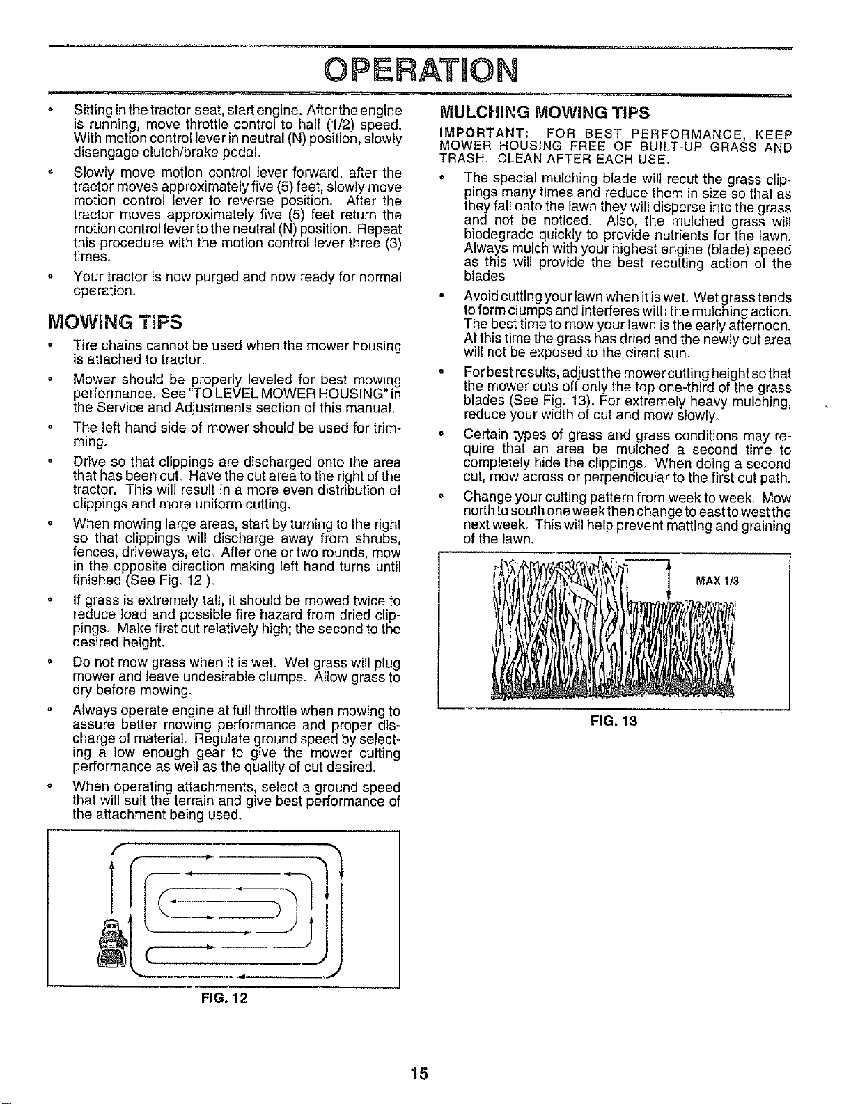
IMPORTANT: FOR BEST PERFORMANCE, KEEP
MOWER HOUSING FREE OF BUILT-UP GRASS AND
TRASH, CLEAN AFTER EACH USE
The special mulching blade will recut the grass clip-
pings many times and reduce them in size so that as
they fall onto the lawn they will disperse into the grass
and not be noticed. Also, the mulched grass will
biodegrade quickly to provide nutrients for the lawn.
Always mulch with your highest engine (blade) speed
as this will provide the best recutting action of the
blades_
° Avoid cuttingyour lawn when it iswet. Wet grass tends
to form clumps and interferes with the mulching action
The best time to mow your lawn isthe early afternoon.
At this time the grass has dried and the newly cut area
will not be exposed to the direct sun.
° For best results, adjust the mower cutting height so that
the mower cuts off only the top one-third of the grass
blades (See Fig. 13), For extremely heavy mulching
reduce your w dth of cut and mow slowly.
° Certain types of grass and grass conditions may re-
quire that an area be mulched a second time to
completely hide the clipping& When doing a second
cut, mow across or perpendicular to the first cut path.
= Change your cutting pattern from week to week, Mow
north to south one week then change to east to west the
next week. This will help prevent matting and graining
of the lawn.
MAX 1/3
FIG. 13
f
_......
FIG. 12
15
CUSTOMER RESPONSnBHLm
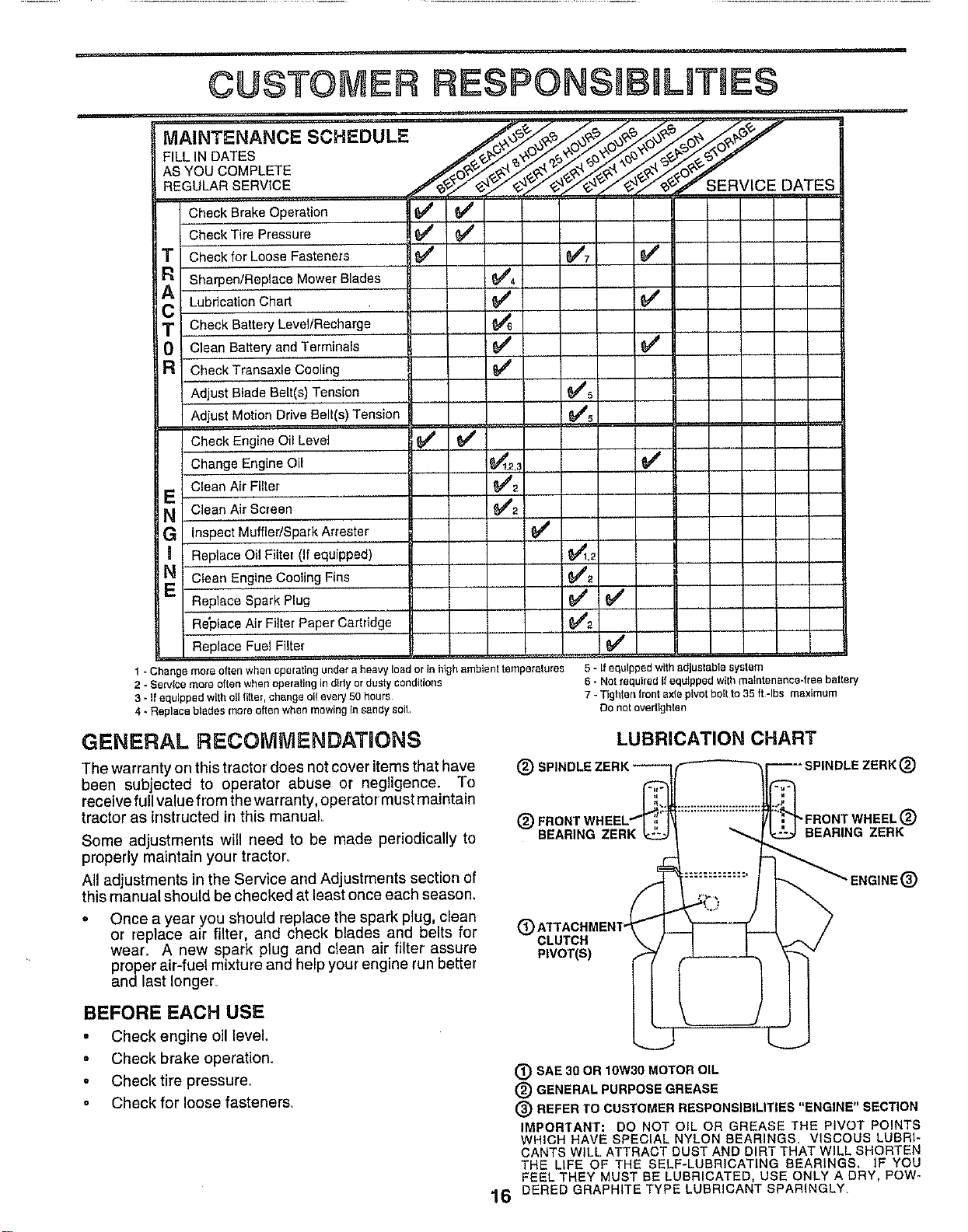
Check Brake Operation 6## _4
Check Tire Pressure _
T Check for Loose Fasteners _ _'t _#
Sharpen/Replace Mower Blades _##4
C Lubrication Chart _
T Check Battery Level/Recharge
i 0 Clean Battery and Terminals 6## _f
R CheckTransaxle Cooling
Adjust Blade Belt(s) Tension Ks
Adjust Motion Drive BelI(s) Tension 6##5
Check Engine Oil Level _#
Change Engine Oil _1,2,_
Clean Air Filter 6##2
E
N Clean Air Screen 6##2
G Inspect MuffledSparkArrester
Replace Oil Filter (If equipped) _,2
N clean Engine Cooling Fins 6##2
Replace Spark Plug _
Re'place Air Filter Paper Cartridge _##2
Replace Fuel Filter 6##
1 - Change more oflen when operating under a heavy load or In high ambient temperalures
2 - Service more often when operating in dirty or dusty conditions
3 - if equipped with oil fl_tel, change ell every 50 hours
4 * Replace blades more often when mowing In sandy soil
5 - If equipped with adjuslable system
6 - Net required If equipped with maintenance-free batlery
7 - Tighlen front axle pivot bolt to 35 ft-Ibs maximum
Do net overtlghlen
GENERAL RECOMMENDATIONS
The warranty on this tractor does not cover items that have
been subjected to operator abuse or negligence. To
receive full value from the warranty, operator must maintain
tractor as instructed in this manual,
Some adjustments will need to be made periodically to
properly maintain your tractor.
All adjustments in the Service and Adjustments section of
this manual should be checked at least once each season.
• Once a year you should replace the spark plug, clean
or replace air filter, and check blades and belts for
wear_ A new spark plug and clean air filter assure
proper air-fuel mixture and help your engine run better
andlast Ionger_
LUBRICATION CHART
@
SEARING ZERK
®
CLUTCH
PIVOT(S)
"FRONT WHEEL(_)
BEARING ZERK
®
BEFORE EACH USE
• Check engine oil level.
. Check brake operation.
o Checktire pressure.
• Check for loose fastener&
® SAE 30 OR 10W30 MOTOR OIL
(_) GENERAL PURPOSE GREASE
® REFER TO CUSTOMER RESPONSIBILITIES "ENGINE" SECTION
IMPORTANT: DO NOT OIL OR GREASE THE PIVOT POINTS
WHICH HAVE SPECIAL NYLON BEARINGS. VISCOUS LUBRI-
CANTS WILL ATTRACT DUST AND DIRT THAT WILL SHORTEN
THE LIFE OF THE SELF-LUBRICATING BEARINGS, IF YOU
FEEL THEY MUST BE LUBRICATED, USE ONLY A DRY, Pew-
16 DERED GRAPHITE TYPE LUBRICANT SPARINGLY
.... i ¸i
CUSTOMER RESPONSUBILRTmES
TRACTOR
Always observe safety rules when performing any mainte-
nance.
BRAKE OPERATION
If tractor requires more than six (8) feet stopping distance
at high speed in highest gear, then brake must be adjusted.
(See "TO ADJUST BRAKE" in the Service and Adjust °
ments section of this manual).
TIRES
• Maintain proper air pressure in all tires (See "PROD-
UCT SPECIFICATIONS" on page 3 of this manual).
o Keep tires free of gasoline, oil, or insect control chemi-
cals which can harm rubber.
. Avoid stumps, stones, deep ruts, sharp objects and
other hazards that may cause tire damage.
NOTE: To seal tire punctures and prevent flat tires due to
slow leaks, tire sealant may be purchased from your local
parts dealer. Tire sealant also prevents tire dry rot and
corrosion_
BLADE CARE
For best results mower blades must be kept sharp_ Re-
place bent or damaged blades.
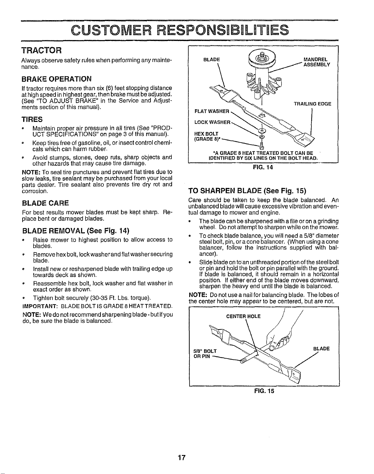
BLADE REMOVAL (See Fig, 14)
• Raise mower to highest position to allow access to
blade&
• Remove hex bolt, Iockwasher and flat washer securing
blade.
o Install new or resharpened blade with trailing edge up
towards deck as shown.
• Reassemble hex bolt, lock washer and flat washer in
exact order as shown.
• Tighten bolt securely (30-35 Ft. Lb& torque).
IMPORTANT: BLADE BOLT IS GRADE 8 HEATTREATED.
NOTE: We do not recommend sharpening blade- but ifyou
do, be sure the blade is balance&
BLADE
FLAT_
LOCK WASHER_
HEX BOLT
(GRADE 8)* _
TRAILING EDGE
*A GRADE 8 HEAT TREATED BOLT CAN BE
IDENTIFIED BY SIX LINES ON THE BOLT HEAD,
FIG. 14
TO SHARPEN BLADE (See Fig. 15)
Care should be taken to keep the blade balanced° An
unbalanced blade will cause excessive vibration and even-
tual damage to mower and engine.
• The blade can be sharpened with a file or on a grinding
wheel. Do not attempt to sharpen whi}e on the mower.
• To check blade balance, you will need a 5/8" diameter
steel bolt, pin, or a cone balancer. (When using a cone
balancer, follow the instructions supplied with bal-
ancer).
° Slide blade on to an unthreaded portion of the steel bolt
or pin and hold the bolt or pin parallel with the ground.
If blade is balanced, it should remain in a horizontal
position. If either end of the blade moves downward,
sharpen the heavy end until the blade is balance&
NOTE: Do not use a nail for balancing blade. The lobes of
the center hole may appear to be centered, but are not.
CENTER HOLE
5/8" BOLT
OR PIN
BLADE
FIG. 15
17
CUSTOM BIL TIE$
BATTERY Change the oil after every 25 hours of operation or at least
once a yearif the tractor is not used for 25 hours in one year,
Check the crankcase oil level before starting the engine
and after each eight (8) hours of operation. Tighten oil fill
cap/dipstick securely each time you check the oil level.
Your tractor has a battery charging system which is suffi-
cient for normal use. However, periodic charging of the
battery with an automotive charger will extend its life.
o Keep battery and terminals clean,,
Keep battery bolts tight,
° Keep small vent holes open,
° Recharge at 6-10 amperes for t houri
TO CLEAN BATTERY AND TERMINALS
Corrosion and dirt on the battery and terminals can cause
the battery to "leak" power.
= Open battery box door,
o Disconnect BLACK battery cable first then RED bat-
tery cable and remove battery from tractor.
• Rinse the battery with plain water and dry.
° Clean terminals and battery cable ends with wire brush
until bright.
o Coat terminals with grease or petroleum jelly.
o Reinstall battery (See "CONNECT BATTERY" in the
Assembly section of this manual).
V-BELTS
Check V-belts for deterioration and wear after' 100 hours of
operation and replace if necessary, The belts are not
adjustable_ Replace belts if they begin to slip from wear.
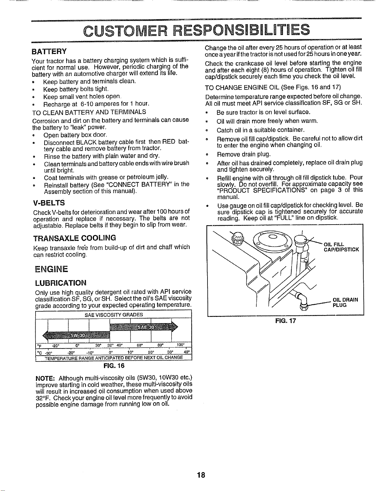
TO CHANGE ENGINE OIL (See Figs. 16 and 17)
Determine temperature range expected before oil change,
All oil must meet API service classification SP, SG or SH,
° Be sure tractor' is on level surface.
° Oil will drain more freely when warm.
° Catch oil in a suitable container.
° Remove oil fill cap/dipstick. Be careful not to allow dirt
to enter the engine when changing oil,
o Remove drain plug.
= After oil has drained completely, replace oil drain plug
and tighten securely.
• Refill engine with oil through oil fill dipstick tube. Pour
slowly. Do not overfill. For approximate capacity see
PRODUCT SPECIFICATIONS" on page 3 of this
manual.
* Use gauge err oil fill cap/dipstick for checking level. Be
sure dipstick cap is tightened securely for accurate
reading. Keep oil at "FULL" line on dipstick.
TRANSAXLE COOLING
Keep transaxle free from build-up of dirt and chaff which
can restrict cooling_
ENGINE
LUBRICATION
Only use high quality detergent oil rated with API service
classification SF, SG, or SH. Select the oil's SAE viscosity
grade according to your expected operating temperature.
L FILL
CAP/DIPSTICK
OIL DRAIN
PLUG
FIG, 17
-20= O" 30" 32° 40"
-30 ° °20° -10" O" 10° 20 ° 300
TEMPERATURE RANGE ANTICIPATED BEFORE NEXT OIL CHANGE
FIG. 16
NOTE-" Although multi-viscosity oils (5W30, 10W30 etc.)
improve starting in cold weather, these multi-viscosity oils
will result in increased oil consumption when used above
32°F. Check your engine oil level more frequently to avoid
possible engine damage from running low on oil.
18
CUSTOMER RIESPONSUBULnTUE$
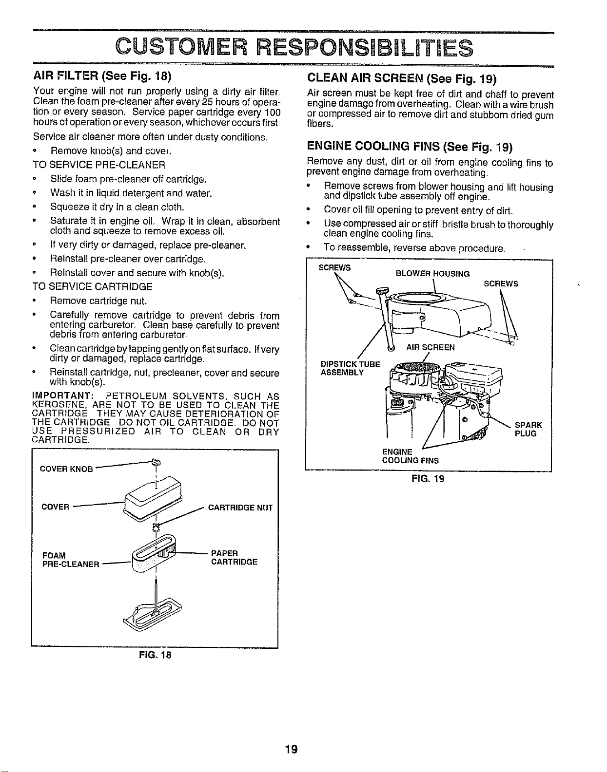
AIR FILTER (See Fig. 18)
Your engine will not run properly using a dirty air filter.
Clean the foam pre-cleaner after every 25 hours ofopera-
tion or every season. Service paper cartridge every 100
hours ofoperation or every season, whichever occursfirsL
Service air cleaner more often under dusty conditions,
o Remove knob(s) and covet.
TO SERVICE PRE-CLEANER
• Slide foam pre-cleaner off cartridge.
• Wash it in liquid detergent and water.
• Squeeze it dry in a clean cloth.
o Saturate it in engine oil.. Wrap it in clean, absorbent
cloth and squeeze to remove excess oil.
o If very dirty or damaged, replace pre-cleaner.
• Reinstall pre-cleaner over cartridge.
Reinstall cover and secure with knob(s).
TO SERVICE CARTRIDGE
o Remove cartridge nut..
• Carefully remove cartridge to prevent debris from
entering carburetor, Clean base carefully to prevent
debris from entering carburetor.
= Clean cartridge by tapping gently on flat surface. Ifvery
dirty or damaged, replace cartridge.
= Reinstall cartridge, nut, precleaner, cover and secure
with knob(s)_
IMPORTANT: PETROLEUM SOLVENTS, SUCH AS
KEROSENE, ARE NOT TO BE USED TO CLEAN THE
CARTRIDGE THEY MAY CAUSE DETERIORATION OF
THE CARTRIDGE DO NOT OIL CARTRIDGE. DO NOT
USE PRESSURIZED AIR TO CLEAN OR DRY
CARTRIDGE.
COVER KNOB _'-'-_
_ PAPER
PRE-CLEANER CARTRIDGE
CLEAN AIR SCREEN (See Fig. 19)
Air screen must be kept free of dirt and chaff to prevent
engine damage from overheating, Clean with a wire brush
or compressed air to remove dirt and stubborn dried gum
fibers,
ENGINE COOLING FINS (See Fig. 19)
Remove any dust. dirt or oil from engine cooling fins to
prevent engine damage from overheating,
• Remove screws from blower housing and lift housing
and dipstick tube assembly off engine_
° Cover oil fill opening to prevent entry of dirL
o Use compressed air or stiff bristle brush to thoroughly
clean engine cooling fins.
• To reassemble, reverse above procedure.
SCREWS
BLOWER HOUSING
SCREWS
DIPSTICK TUBE
ASSEMBLY
AIR SCREEN
ENGINE
COOLING FINS
SPARK
PLUG
FIG. 19
FIG. 18
19
CUSTOMER
i i,i
CLAMP
MUFFLER
Inspect and replace corroded muffler and spark arrester (if
equipped) as itcould create a fire hazard and/or damage,
SPARKPLUGS
Replace spark plugs at the beginning of each mowing
season or after every 100 hours of operation, whichever
occurs first. Spark p{ug type and gap setting are shown in
"PRODUCT SPECIFICATIONS" on page 3 of this manual
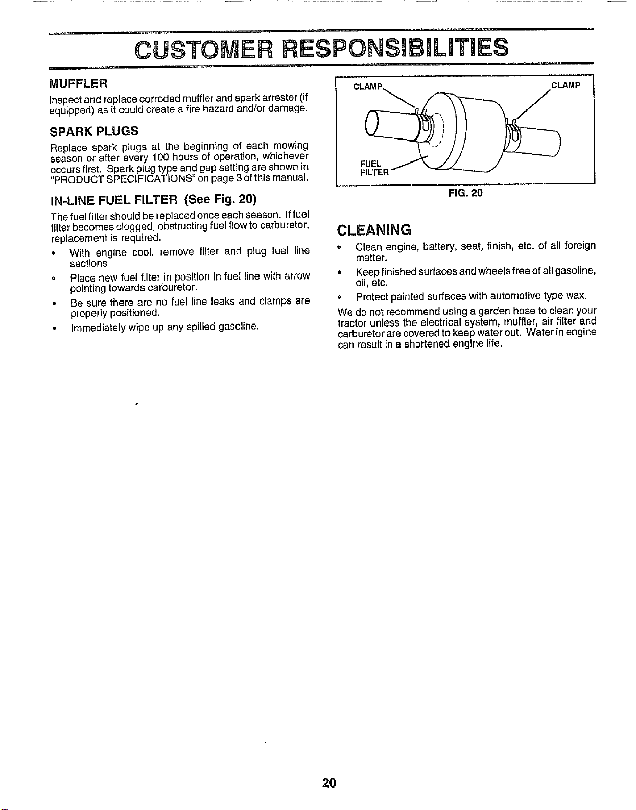
IN-LINE FUEL FILTER (See Fig. 20)
The fuel filter should be replaced once each season. Iffuel
filter becomes clogged, obstructingfuel flow to carburetor,
replacement is required.
= W{th engine coot, remove fitter arrd plug fuet line
sections_
= Place new fuel filter in position in fuel line with arrow
pointing towards carburetor.
= Be sure there are no fuel line leaks and clamps are
properly positioned.
° Immediately wipe up any spilled gasoline.
FUEL
FIG. 20
CLEANING
, Clear} engine, battery, seat, finish, etc. of aJIforeign
matter.
• Keep finished surfaces and wheels free of all gasoline,
oil, etc.
• Protect painted surfaces with automotive type wax.
We do not recommend using a garden hose to clean your
tractor unless the electrical system, muffler, air filter and
carburetor are covered to keep water out. Water in engine
can result in a shortened engine life.
20
SERVBCF= ADJUSTMENTS
CAUTION: BEFORE PERFORMING ANY SERVICE OR ADJUSTMENTS:
o
o
Q
o
o
o
Depress clutch/brake pedal fully and set parking brake.
Place motion control lever in neutral (N) position.
Place attachment clutch in "DISENGAGED" position.
Turn ignition key "OFF" and remove key.
Make sure the blades and all moving parts have completely stopped.
Disconnect spark plug wire from spark plug and place wire where it cannot come in contact
with plug.
TRACTOR
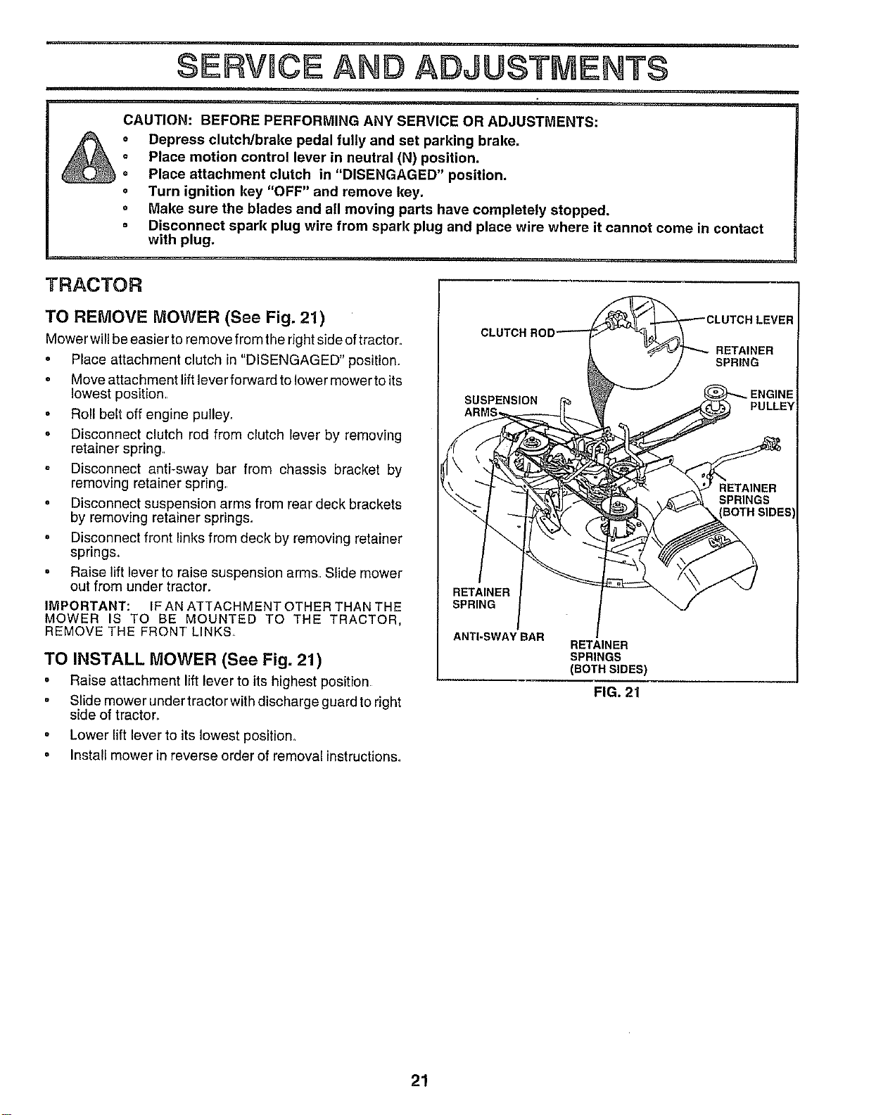
TO REMOVE MOWER (See Fig. 21)
Mower willbe easier to remove from the right side oftractor.
• Place attachment clutch in "DISENGAGED" position_
° Move attachment lift lever forward to lower mower to its
lowest position..
° Roll belt off engine pulley.
o Disconnect clutch rod from clutch lever by removing
retainer spring.
Disconnect anti-sway bar from chassis bracket by
removing retainer spring.
o Disconnect suspension arms from rear deck brackets
by removing retainer springs.
° Disconnect front links from deck by removing retainer
spnngs,
= Raise lift lever to raise suspension arms. Slide mower
out from under tractor.
IMPORTANT: IF AN ATTACHMENT OTHER THAN THE
MOWER IS TO BE MOUNTED TO THE TRACTOR,
REMOVE THE FRONT LINKS
TO INSTALL MOWER (See Fig. 21)
° Raise attachment lift lever to its highest position
° Slide mower under tractor with discharge guard to right
side of tractor.
= Lower lift lever to its lowest position.
= Install mower in reverse order of removal instructions..
CLUTCH I
RETAINER
SPRING
ANTI-SWAY BAR
RETAINER
SPRINGS
(BOTH SIDES)
FIG. 21
21
SERVICE AND ADJUSTMENTS
TO LEVEL MOWER HOUSING
Adjust the mower while tractor isparked on level ground or
driveway, Make sure tires are properly inflated (See
"PRODUCT SPECIFICATIONS" on page 3 ofthis manual),
If tires are over or undednflated, you will not properly adjust
your mower.
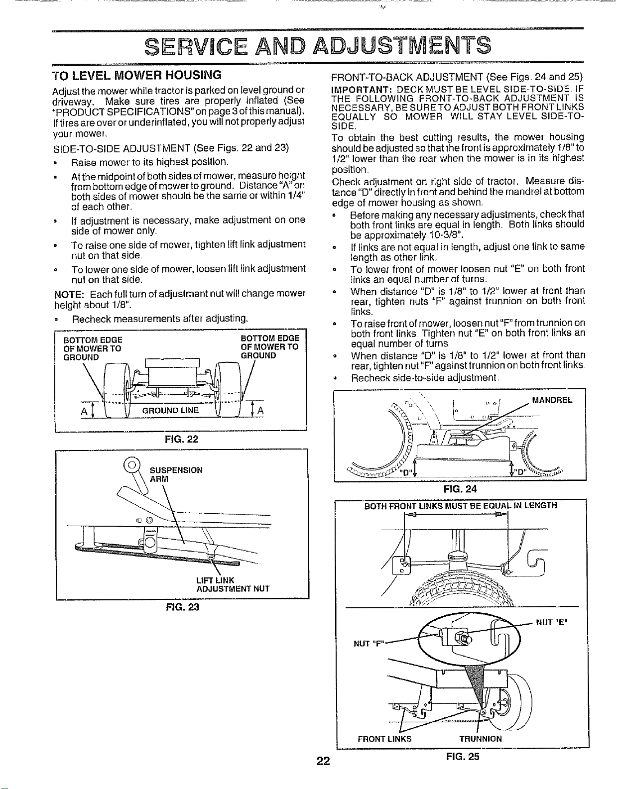
SIDE-TO-SIDE ADJUSTMENT (See Figs. 22 and 23)
• Raise mower to its highest position.
• At the midpoint of both sides of mower, measure height
from bottom edge of mower to ground. Distance "A" orr
both sides of mower should be the sarr_eor within 1/4"
of each other.
If adjustment is necessary, make adjustment on one
side of mower only
To raise one side of mower, tighten lift link adjustment
nut on that side.
= To lower one side of mower, loosen lift link adjustment
nut on that side,
NOTE: Each full turn of adjustment nut will change mower
height about 1/8".
Recheck measurements after adjusting_
BO3-FOM EDGE BOTTOM EDGE
OF MOWER TO OF MOWER TO
GROUND GROUND
FIG, 22
SUSPENSION
ARM
LIFT LINK
ADJUSTMENT NUT
FIG. 23
FRONT-TO-BACK ADJUSTMENT (See Figs. 24 and 25)
IMPORTANT; DECK MUST BE LEVEL SIDE-TO-SIDE IF
THE FOLLOWING FRONT-TO-SACK ADJUSTMENT IS
NECESSARY, BE SURE TO ADJUST BOTH FRONT LINKS
EQUALLY SO MOWER WILL STAY LEVEL SIDE-TO-
SIDE_
To obtain the best cutting results, the mower housing
should be adjusted so that the front is approximately 1/8" to
1/2" lower than the rear when the mower is in its highest
position
Check adjustment on right side of tractor_ Measure dis-
tance "D" directly infront and behind the mandrel at bottom
edge of mower housing as shown.
o Before making any necessary adjustments, check that
both front links are equal in length_ Both links should
be approximately 10-3/8".
= If links are not equal in length, adjust one link to same
length as other link_
To lower front of mower loosen nut "E" on both front
links an equal number of turns_
When distance "D" is 1/8" to 1/2" lower at front than
rear, tighten nuts "F" against trunnion on both front
links.
= To raise front of mower, loosen nut "F" from trunnion on
both front links. Tighten nut "E" on both front links an
equal number of turns
= When distance "D" is 1/8" to 1/2" lower at front than
rear, tighten nut "F" against trunnion on both front links
= Recheck side-to-side adjustment.
MANDREL
FIG. 24
BOTH FRONT LINKS MUST BE EQUAL IN LENGTH
__2__
NUT "F"'_
FRONT LINKS
NUT"E"
TRUNNION
22 FIG. 25
SERVICE ADJUSTMENTS
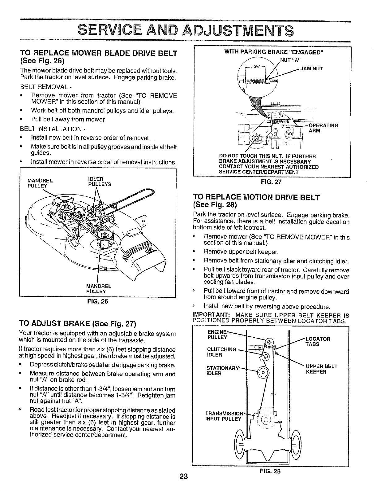
TO REPLACE MOWER BLADE DRIVE BELT
(See Fig. 26)
The mower blade drive belt may be replaced without tools.
Park the tractor on level surface,, Engage parking brake_
BELT REMOVAL -
o Remove mower from tractor (See "TO REMOVE
MOWER" in this section of this manual),
o Work belt off both mandrel pulleys and idler pulleys.
• Pull belt away from mower.
BELT INSTALLATION -
• Install new belt in reverse order of removal
o Make sure belt is in all pulley grooves and inside all belt
guides.
• Install mower in reverse order of removal instructions.
MANDREL IDLER
PULLEY PULLEYS
MANDREL
PULLEY
FIG. 26
TO ADJUST BRAKE (See Fig. 27)
Your tractor is equipped with an adjustable brake system
which is mounted on the side of the transaxle,
If tractor requires more than six (6) feet stopping distance
at high speed in highest gear, then brake must be adjusted.
• Depress clutch/brake pedal and engage parking brake,
, Measure distance between brake operating arm and
nut "A" on brake rod_
If distance is other than 1-3/4" loosen jam nut and turn
nut A until distance becomes 1-3/4'L Retighten jam
nut against nut "A".
Road test tractor for proper stopping distance as stated
above° Readjust if necessary. If stopping distance is
still greater than six (6) feet in highest gear, further
maintenance is necessary. Contact your nearest au-
thorized service center/department.
WITH PARKING BRAKE "ENGAGED"
NUT "A"jA M NUT
_ 3_F=___ OPERATING
/_J o ,_ ,_,1 I ARM
-"
DO NOT TOUCH THIS NUT. IF FURTHER
BRAKE ADJUSTMENT IS NECESSARY
CONTACT YOUR NEAREST AUTHORIZED
SERVICE CENTER/DEPARTMENT
FIG. 27
TO REPLACE MOTION DRIVE BELT
(See Fig. 28)
Park the tractor on _evelsurface. Engage parking brake.
For assistance, there is a belt installation guide decal on
bottom side of left footrest.
• Remove mower (See "TO REMOVE MOWER" in this
section of this manuaL)
° Remove upper belt keeper,
• Remove belt from stationary idler and clutching idler.,
° Pull belt slack toward rear of tractor_ Carefully remove
belt upwards from transmission input pulley and over
cooling fan blades°
° Pull belt toward front of tractor and remove downward
from around engine pulley.
• Install new belt by reversing above procedure.
IMPORTANT." MAKE SURE UPPER BELT KEEPER IS
POSITIONED PROPERLY BETWEEN LOCATOR TABS.
ENGINE_
PULLEY
CLUTCHING
IDLER
STATIONARY"_
IDLER
TRANSMISSION,
INPUT PULLEY
0
_LOCATOR
TABS
_UPPER BELT
KEEPER
i
FIG. 28
23
SERWCE ADJUSTMENTS
TO ADJUST MOTION CONTROL LEVER (See
Fig. 29)
The motion control lever has been preset at the factory and
adjustment should not be necessary.
tf for any reason the motion control lever will not hold its
position while at a selected speed, it may be adjusted at the
friction pack located on the right side of transmission.
. Park tractor on level surface Stop tractor by turning
ignition key to "OFF" position, and engage parkfng
brake.
• Adjust motion control lever by tightening adjustment
Iocknut one half (1/2) turn_
NOTE: If for any reason the effort to move the motion
control lever becomes too excessive, reverse the above
adjustment procedure by loosening Iocknut 1/4 to 1/2 tum.
Road test tractor after adjustment and repeat procedure if
necessary.
TRANSMISSION REMOVAL/REPLACEMENT
Should your transmission require removal for service or
replacement, it should be purged after reinstallation and
before operating the tractor. See "PURGE TRANSMIS-
SION" in the Operation section of this manual,
ADJUSTMENT
LOCKNUT
FIG. 29
TO ADJUST STEERING WHEEL ALIGNMENT
If steering wheel crossbars are not horizontal (left to right)
when wheels are positioned straight forward, remove steer-
ing wheel and reassemble per instructions in the Assembly
section of this manual.
FRONT WHEEL TOE-IN/CAMBER
The front wheel toeqn and camber are not adjustable on
your tractor. If damage has occurred to affect the front
wheel toe-in or' camber, contact your nearest authorized
service center?department.
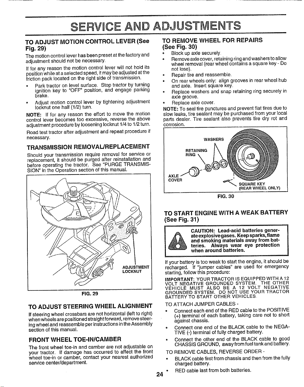
TO REMOVE WHEEL FOR REPAIRS
(See Fig. 30)
" Block up axle securely
• Remove axle cover, retaining ring and washers to allow
wheel removal (rear wheel contains a square key - Do
not lose).
o Repair tire and reassemble_
• On rear wheels only: align grooves in rear wheel hub
and axle_ Insert square key.
o Replace washers and snap retaining ring securely in
axle groove.
o Replace axle cover.
NOTE: To seal tire punctures and prevent flat tires due to
slow leaks, tire sealant may be purchased from your local
parts dealer. Tire sealant also prevents tire dry rot and
corrosion.
WASHERS
RETAINING
RING
AXLE
COVER
_,.SQUARE KEY
(REAR WHEEL ONLY)
FIG. 30
TO START ENGINE WITH A WEAK BATTERY
(See Fig, 31)
&
CAUTION: Lead-acid batteries gener-
ate explosive gases. Keep sparks, flame
and smoking materials away from bat-
teries. Always wear eye protection
when around batteries,
ff your battery is too weak to start the engine, it should be
recharged. If "jumper cables" are used for emergency
starting, follow this procedure:
IMPORTANT: YOUR TRACTOR IS EQUIPPED WITH A 12
VOLT NEGATIVE GROUNDED SYSTEM. THE OTHER
VEHICLE MUST ALSO BE A 12 VOLT NEGATIVE
GROUNDED SYSTEM. DO NOT USE YOUR TRACTOR
BATTERY TO START OTHER VEHICLES
TO ATTACH JUMPER CABLES -
= Connect each end of the RED cable to the POSITIVE
(+) terminal of each battery, taking care not to short
against chassis,
o Connect one end of the BLACK cable to the NEGA-
TIVE (-) terminal of fully charged battery,
= Connect the other end of the BLACK cable to good
CHASSIS GROUND, away from fuel tank and battery_
TO REMOVE CABLES, REVERSE ORDER -
• BLACK cable first from chassis and then from the fully
charged battery.
RED cable last from both batteries,,
24"
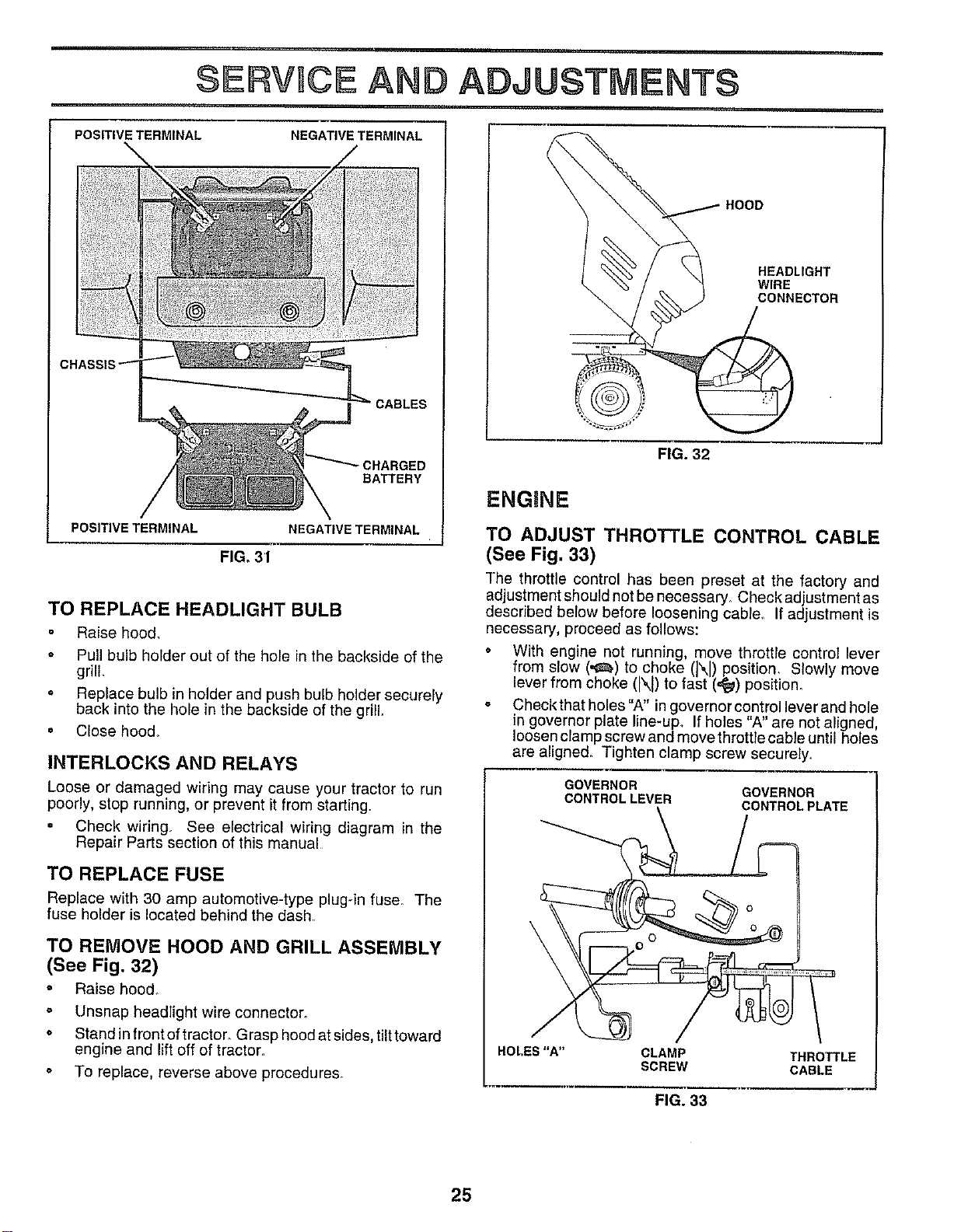
SERVICE ADJUSTMENTS
POSITIVE TERMINAL NEGATIVE TERMINAL
D
BATTERY
POSITIVE TERMINAL NEGATIVE TERMINAL
FIG, 3'1
TO REPLACE HEADLIGHT BULB
Raise hoe&
o Pull bulb holder out of the hole in the backside of the
grill,
o Replace bulb in holder and push bulb holder securely
back into the hole in the backside of the grill
= Close hood°
INTERLOCKS AND RELAYS
Loose or damaged wiring may cause your tractor to run
poorly, stop running, or prevent it from starting.
• Check wiring, See electrical wiring diagram in the
Repair Parts section of this manual
TO REPLACE FUSE
Replace with 30 amp automotive-type plug-in fuse The
fuse holder is located behind the dash
TO REMOVE HOOD AND GRILL ASSEMBLY
(See Fig, 32)
= Raise hood°
° Unsnap headlight wire connector.
= Stand in front of tractor. Grasp hood at sides, tilt toward
engine and lift off of tractor.
° To replace, reverse above procedures.
HOOD
HEADLIGHT
WIRE
CONNECTOR
FIG. 32
ENGUNE
TO ADJUST THROTTLE CONTROL CABLE
(See Fig. 33)
The throttle control has been preset at the factory and
adjustment should not be necessary. Check adjustment as
described below before loosening cable. If adjustment is
necessary, proceed as follows:
° With engine not running, move throttle control lever
from slow (,,_) to choke (N) position, Slowly move
lever from choke (1\I)to fast (,_) position.
° Checkthat holes"A" in governor control lever and hole
in governor plate line-up If holes "A" are not alinned
loosen clamp screw and move throttle cable unhl holes
are aligned. Tighten clamp screw securely.
GOVERNOR
CONTROLLEVER
GOVERNOR
CONTROLPLATE
HOLES"A" CLAMP THROTTLE
SCREW CABLE
FIG. 33
25
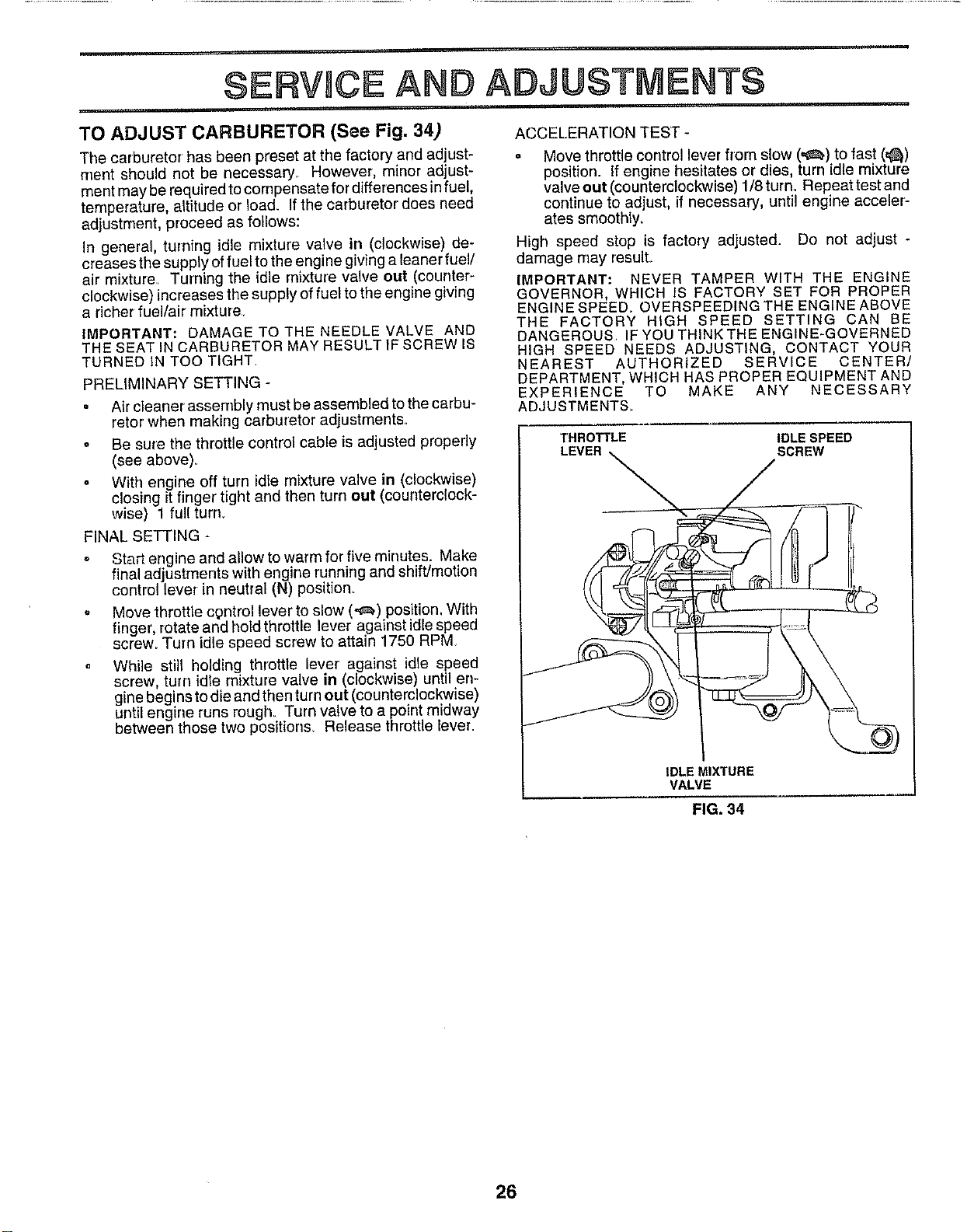
SERVICE AND ADJUSTMENTS
i,
TO ADJUST CARBURETOR (See Fig. 34) ACCELERATION TEST -
The carburetor has been preset at the factory and adjust-
rtlent should not be necessary. However, minor adjust-
ment may be required tocompensate for differences in fuel,
temperature, altitude or load. If the carburetor does need
adjustment, proceed as follows:
In general, turning idle mixture valve in (clockwise) de-
creases the supply of fuel to the engine giving a leaner fuel/
air mixture. Turning the idle mixture valve out (counter-
clockwise) increases the supply of fuel to the engine giving
a richer fuel/air mixture.
IMPORTANT: DAMAGE TO THE NEEDLE VALVE AND
THE SEAT IN CARBURETOR MAY RESULTIFSCREW 18
TURNED IN TOO TIGHT,
PRELIMINARY SETTING -
o
o
Air cleaner assembly must be assembled to the carbu-
retor when making carburetor adjustments.
Be sure the throttle contro_ cable is adjusted properly
(see above)_
With engine off turn idle mixture valve in (clockwise)
closing it finger tight and then turn out (counterclock-
wise) 1 fuUturn.
FINAL SETTING
Start engine and allow to warm for five minutes. Make
final adjustments with engine running and shift/motion
control lever in neutral (N) position.
Move throttle cgntrol lever to slow (_) position, With
finger, rotate and hold throttle lever against idle speed
screw_ Turn idle speed screw to attain 1750 RPM
While still holding throttle lever' against idle speed
screw, turn idle mixture valve in (clockwise) until en-
gine begins to die and then turn out (counterclockwise)
until engine runs rough. Turn valve to a point midway
between those two positions_ Release throttle lever.
o Move throttle control lever from slow (_) to fast (,_)
position. If engine hesitates or dies, turn idle mixture
valve out (counterdockwise) 1/8 turn. Repeat test and
continue to adjust, if necessary, until engine acceler-
ates smoothly.
High speed stop is factory adjusted. Do not adjust -
damage may result.
IMPORTANT: NEVER TAMPER WITH THE ENGINE
GOVERNOR, WHICH IS FACTORY SET FOR PROPER
ENGINE SPEED. OVERSPEEDING THE ENGINE ABOVE
THE FACTORY HIGH SPEED SETTING CAN BE
DANGEROUS. IF YOU THINK THE ENGINE-GOVERNED
HIGH SPEED NEEDS ADJUSTING, CONTACT YOUR
NEAREST AUTHORIZED SERVICE CENTER/
DEPARTMENT, WHICH HAS PROPER EQUIPMENT AND
EXPERIENCE TO MAKE ANY NECESSARY
ADJUSTMENTS_
THROTTLE IDLE SPEED
LEVER _ SCREW
IDLE MIXTURE
VALVE
FIG. 34
26
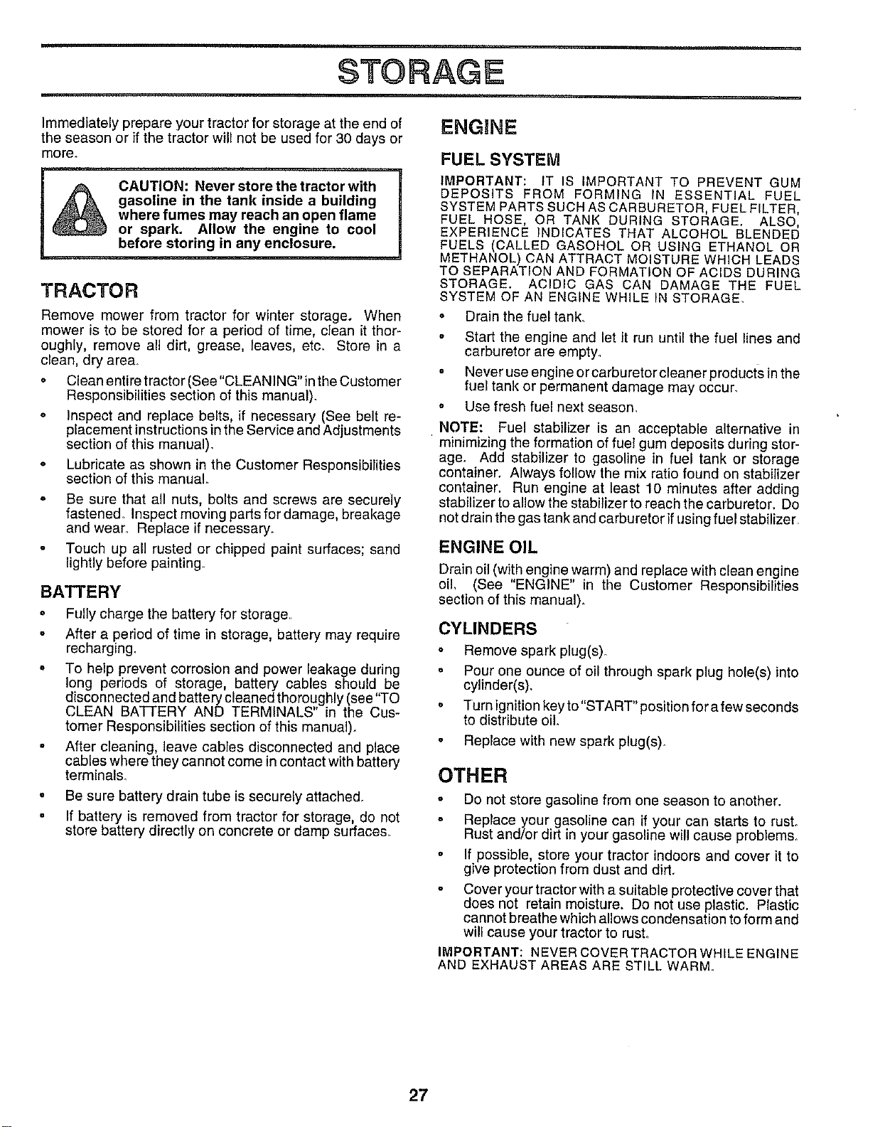
Immediately prepare your tractor for storage at the end of
the season or if the tractor will not be used for 30 days or
more.
CAUTION: Never store the tractor with
gasoline in the tank inside a building
where fumes may reach an open flame
or spark. Allow the engine to cool
before storing in any enclosure.
TRACTOR
o
o
Remove mower from tractor for winter storage. When
mower is to be stored for a period of time, clean it thor-
oughly, remove all dirt, grease, leaves, etc. Store in a
clean, dry area.
o Clean entire tractor (See"CLEANING"in the Customer
Responsibilities section of this manual).
o Inspect and replace belts, if necessary (See belt ra-
placement instructions in the Service and Adjustments
section of this manual).
Lubricate as shown in the Customer Responsibilities
section of this manual,
Be sure that all nuts, bolts and screws are securely
fastened. Inspect moving parts for damage, breakage
and wear. Replace if necessary.
Touch up all rusted or chipped paint surfaces; sand
lightly before painting,
BATTERY
o Fully charge the battery for storage,,
After a period of time in storage, battery may require
recharging.
o To help prevent corrosion and power leakage during
long periods of storage, battery cables should be
disconnected and battery cleaned thoroughly (see "TO
CLEAN BATTERY AND TERMINALS" in the Cus-
tomer Responsibilities section of this manual).
= After cleaning, leave cables disconnected and place
cables where they cannot come incontact with battery
terminals.
o Be sure battery drain tube issecurely attached.
° If battery is removed from tractor for storage, do not
store battery directly on concrete or damp surfaces,
FUEL SYSTEM
IMPORTANT: IT IS IMPORTANT TO PREVENT GUM
DEPOSITS FROM FORMING IN ESSENTIAL FUEL
SYSTEM PARTS SUCH AS CARBURETOR, FUEL FILTER,
FUEL HOSE, OR TANK DURING STORAGE, ALSO,
EXPERIENCE INDICATES THAT ALCOHOL BLENDED
FUELS (CALLED GASOHOL OR USING ETHANOL OR
METHANOL) CAN ATTRACT MOISTURE WHICH LEADS
TO SEPARATION AND FORMATION OF ACIDS DURING
STORAGE, ACIDIC GAS CAN DAMAGE THE FUEL
SYSTEM OF AN ENGINE WHILE IN STORAGE,
o Drain the fuel tank.
° Start the engine and let it run until the fuel lines and
carburetor are empty.
• Never use engine or carburetorcleaner products inthe
fuel tank or permanent damage may occur.
° Use fresh fuel next season.
NOTE: Fuel stabilizer is an acceptable alternative in
minimizing the formation of fuel gum deposits during stor-
age. Add stabilizer to gasoline in fuel tank or storage
container. Always follow the mix ratio found on stabilizer
container. Run engine at least 10 minutes after adding
stabilizer to allow the stabilizer to reach the carburetor, Do
not drain the gas tank and carburetor ifusing fuel stabilizer
ENGINE OIL
Drain oil (with engine warm) and replace with clean engine
oil (See "ENGINE" in the Customer Responsibilities
section of this manual).
CYLINDERS
• Remove spark plug(s).
= Pour one ounce of oil through spark plug hole(s) into
cylinder(s).
= Turn ignition key to"START" position for a few seconds
to distribute oil
• Replace with new spark plug(s).
OTHER
o Do not store gasoline from one season to another.
o Replace your gasoline can if your can starts to rusL
Rust and/or dirt in your gasoline will cause problems.
° If possible, store your tractor indoors and cover it to
give protection from dust and dirt,
Cover your tractor with a suitable protective cover that
does not retain moisture. Do not use plastic. Plastic
cannot breathe which allows condensation to form and
will cause your tractor to rusL
IMPORTANT: NEVER COVER TRACTOR WHILE ENGINE
AND EXHAUST AREAS ARE STILL WARM
27

TROUBLESHOOTUNG POmNTS
CAUSE CORRECTION
PROBLEM
Will not start
Hard to start
m
Engine will not turn over
Engine clicks but will not
start
Loss ofpower
Excessive vibration
1 Out of fuel
2 Engine not"CHOKED" properly
3 Engine flooded
4 Bad sparkplug
5 Dirty air filter
6 Dirty fue! filter
7 Water in fuel
8 Looseor damaged wiring
9 Carburetor outof adjustment
10 Engine valves out of adjustment
1 Dirty air filter
2 Bad spark plug
3. Weak or dead battery
4. Dirty fuel figer
5 Stale or dirty fuel
6 Loose or damaged wiring
7 Carburetor out of adjustment
8. Enginevalves outofadjustment
1. Clutch/brake pedal not depressed
2 Attachment clutch is engaged
3_ Weak or deed battery
4 Blown fuse
5 Corroded battery terminals
6 Loose or damaged widng_
7 Faulty ignition switch
8 Faulty solenoid or starter
9 Faulty operator presence switch(es).
1_ Weaker dead hattery_
2 Corroded batterytermtnals
3 Loose or damagedwidng
4 Faulty solenoid orstarter
1 Cutting toomuchgrass/too fast
2. Throttle in "CHOKE"position,
3 Build-upof grass,leaves andtrashundermower,,
4 Dirtyair filter.
5 Lowoillevel/dirtyoil,
6 Faultysparkplug
7 Ditty fuel filter
8 Stale or dirty fuel
9 Water Infuel
10. Spark plug wireloose
11_ Dirty engine air screen/fins
12 Dirty/clogged muffler
13 Loose or damaged widng_
14 Carburetor oat of adjustment,
15_ Engine valvesoutof adjustment
1 Worn, bent or loose blade
2 Bent blade mandrel
3 Loose/damaged part(s)_
1 Fill fuel tank.
2 See "TO START ENGINE" tn Operation section
3 Wait several minutes before attempting to start
4 Replace spark plug.
5 Clean/replace ak filter
6 Replace fuel filter
7 Drain fuel tank and carburetor, refill tank with fresh
gasoline and replace fuel filter
8. Check all wiring.
9 See "To Adjust Carburetor" in Service Adjustments
section.
10 Contact an authodzed service center/department
1 Clean/replace air filter
2 Replace spark plug
3 Recharge or replace battery
4_ Replace fuel filter.
5 Drain fuel tank and refill with fresh gasoline
6 Check all wiring.
7 Sea "To Adjust Carburetor" in Service Adjustments
section
8 Contact an authorized service center/department
1 Depress clutch/brake pedal
2 Disengage attachment clutch
3. Recharge or replace battery
4 Replace fuse
5 Clean battery terminals
6 Check a!l wiring
7. Checldreplace ignition switch
8 Checldreplace solenoid or starter.
9 Contact an authorized service center/department
1 Recharge or replace battery
2. Clean battery terminals
3 Check all wiring
4 Check/replace solenoidor starter
1 Set _n"Higher Cut"position/reduce speed.
2, Adjust throttlecontrol.
3. Clean underside of mower housing
4 Clean/replace airfilter,
5 Check oil leve!/changeoil
6. Clean and regapor change sparkplug
7. Replacefuel filter
8 Drainfuel tank and refill with fresh gasoline,
9 Drain fuel tankand carburetor, refill tank with fresh
gasoline and replace fuel filter
10 Connect andtighten spark plug wire.
11 Clean engine air screen/fins
12 Clean/replacemuffler.
13. Check all wiring.
14 See"ToAdjust Carburetor" InService Adjustments
section.
15 Contact an authorized service center/department
1 Replace blade. Tighten blade bolt
2 Replace blade mandrel,
3 Tighten loosepart(s) Replace damaged parts
28
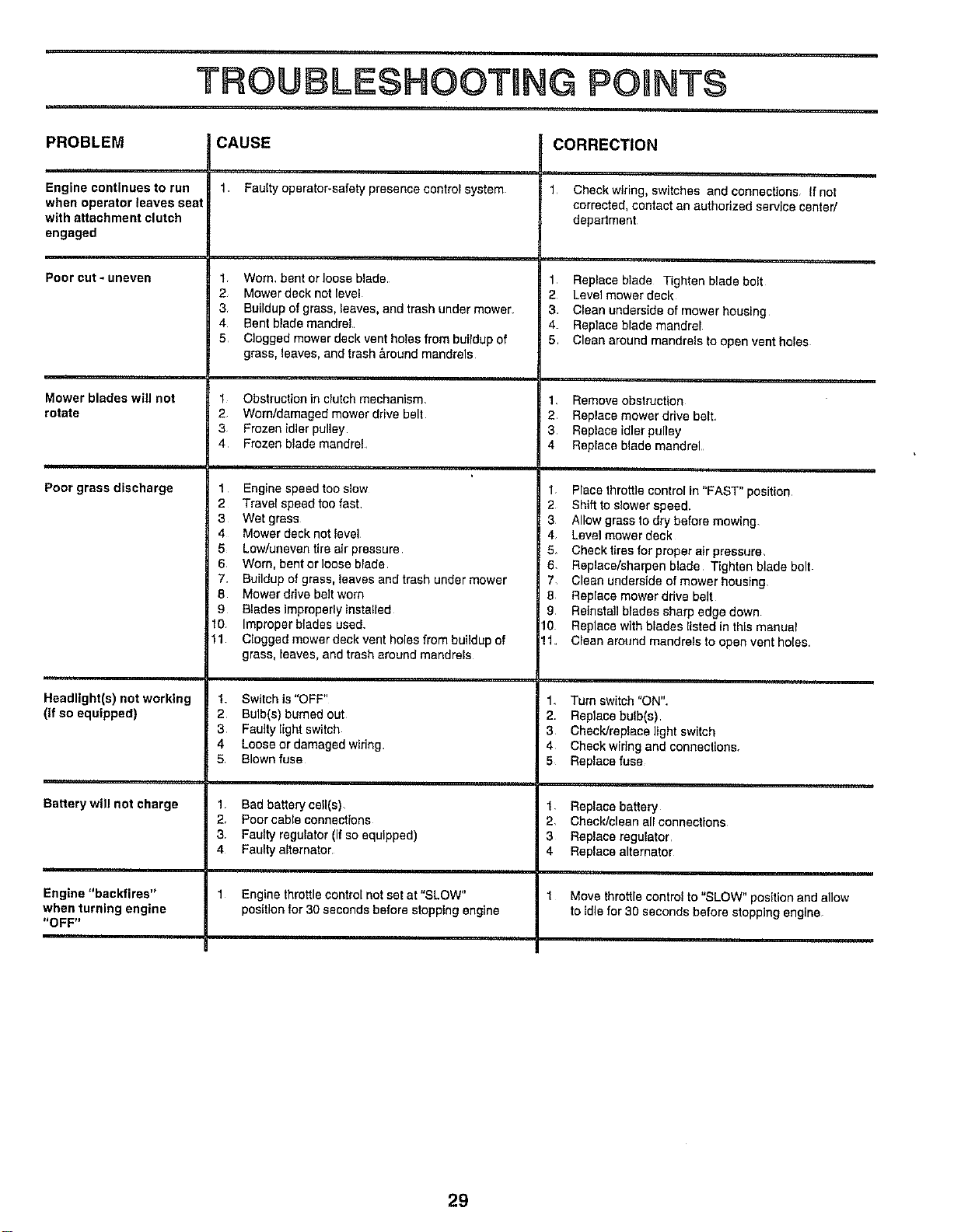
TROU !SHOOTnNG POUNTS
PROBLEM CAUSE CORRECTION
Engine continues to run
when operator leaves seat
with attachment clutch
engaged
Pooreut-uneven
Mower blades wgl not
rotate
Poor grass discharge
Headlight(s) not working
(ifso equipped)
Battery will not charge
Engine "backfires"
when turning engine
"OFF"
1 Faulty operator-safety presence control system
1 Worn. bent or loose blade
2 Mowerdeck notlevel
3 Buildup of grass, leaves, and trash under mower.
4 Bent blade mandrel
5 Clogged mower deck vent holes from buildup of
grass, leaves, and trash &round mandrels
1 Obstruction in clutch mechanism.
2 Wom/damaged mower drive belt
3 Frozen idler pulley
4 Frozen blade mandrel
1 Engine speed too slow
2 Travel speed too fast
3 Wet grass
4 Mower deck not level
5 Low/uneventire air pressure
6 Worn, bent orloose blade
7 Buildup of grass, leaves and trash under mower
8 Mowerdrive beltwom
9 Blades improperly installed
t0 Improper blades used
11 Clogged mower deck vent holes from buildup of
grass, leaves, and trash around mandrels
! Switch is "OFF"
2 Bulb(s) burned out
3 Faufty light switch
4 Loose or damaged widng
5 Blown fuse
1 Bad battery cell(s),
2, Poorcable connectfons
3, Faultyregulator (if so equipped)
4 Faulty alternator
1 Engine throttlecontrol not set at "SLOW"
position for 30 seconds before slopping engine
1 Checkwtring, switches and connections If not
corrected, contact an authorized service center/
depadment
1 Replace blade Tighten blade bolt
2 Level mower deck
3 Clean underside of mower housing
4 Replace blade mandrel
5 Clean around mandrels to open vent holes
1 Removeobstruction
2, Replace mower drive belt+
3 Replace idler pulley
4 Replace blade mandrel
1 Place throttlecontrol In"FAST" position
2 Shiftto slower speed.
3 Allow grassto dry before mowing,
4 Levelmower deck
5+ Check tires for proper air pressure,
6, Replace/sharpen blade Tighten blade bolt
7, Clean underside of mower housing
8 Replace mower ddve belt
9 Relnstallblades sharp edgedown
10 Replacewith blades I_stedinthis manual
11 Clean around mandrels to open vent holes
1 Turn switch "ON"+
2. Replace bulb(s)
3 CheclVreplace light switch
4 Check wiring and connections.
5 Replace fuse
1 Replacebattery
2, Cheek/cleanall connections
3 Replace regulator
4 Replace alternator
1 Move throttle control to "SLOW" posltlon and allow
to Idle for 30 seconds before stopping engine
29

SERVICE NOTES
3O